Embed Size (px)
Citation preview

YSI 9300 and 9500
Photometers
User Manual
®

YSI 9300 and 9500
Direct-Read Photometers
User Manual
YSI, Inc.
1725 Brannum Lane Yellow Springs, OH 45387
Tel: 800-897-4151 (+1 937-767-7241) Fax: +1 937-767-1058 E-Mail: [email protected]
®

INDEX
1 INTRODUCTION .............................................................................................................. 1
Features and Technical Specification ................................................................................ 3 2 OPERATING PRINCIPLE ................................................................................................... 4
Powering the Photometer .................................................................................................. 4 Replacing the Batteries ...................................................................................................... 5 Power Supply (Model 9500 only) ....................................................................................... 5
3 GENERAL PHOTOMETER OPERATION ............................................................................... 6
Operating Modes ............................................................................................................... 6 System - Quick Start .......................................................................................................... 6 System - Full Options ........................................................................................................ 7 View Log (9500 Only) ........................................................................................................ 7 Back Light.......................................................................................................................... 7 Language Options ............................................................................................................. 7 Units .................................................................................................................................. 8 Sample Number (9500 Only) ............................................................................................. 8 Sample Number Increment (9500 Only) ............................................................................. 8 Dilution Factor (9500 Only) ................................................................................................ 8 Date and Time (9500 Only) ................................................................................................ 8 Date Format (9500 Only) ................................................................................................... 8 Battery Level ..................................................................................................................... 8 Locking System Mode Settings (9500 Only) ...................................................................... 9 Rounding (9500 Only) ........................................................................................................ 9 Time-Out (9500 Only) ........................................................................................................ 9 Edit User Defined Tests (9500 Only).................................................................................. 9 USB (9500 Only) ............................................................................................................. 10
4 INTERFACE CONNECTIONS AND DATA MEMORY (9500 ONLY) ......................................... 11
5 TAKING PHOTOMETER READINGS................................................................................... 12
Program Numbers and Test Instructions .......................................................................... 12 Sample Dilution (9500 Only) ............................................................................................ 12 Blank and Sample Tubes ................................................................................................. 12 Light Cap ......................................................................................................................... 13 Getting the Best Results .................................................................................................. 13 Taking Test Readings ...................................................................................................... 13 Continuation Tests (Certain Tests Only) .......................................................................... 16 Favorite Tests List ........................................................................................................... 16 Expressing Different Chemical Forms .............................................................................. 16 Reading in Transmittance and Absorbance ..................................................................... 17 Timer ............................................................................................................................... 17 User Defined Tests (9500 Only) ....................................................................................... 17
6 CARE AND MAINTENANCE .............................................................................................. 20
Cleaning the Optics ......................................................................................................... 20 Service Requirement ....................................................................................................... 20 Error Messages ............................................................................................................... 20 Photometer Up-Grade (9500 only) ................................................................................... 21 Computer Controlled Operation (9500 Only) .................................................................... 21 Warranty .......................................................................................................................... 21 Limitation of Warranty ...................................................................................................... 22 Contact Information ......................................................................................................... 22
Y- PT 282

1
1 INTRODUCTION
The YSI 9300 and 9500 direct-read photometers are designed to give long and
trouble-free operation. To ensure the best results, please read this manual carefully and follow the procedures recommended. This manual covers both
the 9300 and 9500 photometers. Therefore, some of the information only pertains to the 9500 as is noted in the appropriate sections.
The Photometers feature digital electronics and built-in filters. It is lightweight
and portable for field or laboratory use. The instruments are rugged, durable and IP-67 rated. Additionally, the photometers are direct-reading, have
automatic blank setting, automatic wavelength selection, and automatic power cut-off.
The following pages describe the use of the photometers, and give
instructions for the wide range of water tests which can be performed using these instruments.
Keep the photometer clean and in good working order by adhering to the following recommendations:
Do not pour out samples or prepare the tests directly over the instrument.
Always cap the test tubes before inserting into the instrument for readings.
Wipe test tubes with a clean tissue to remove drips or condensation before
placing in the photometer.
Do not leave tubes standing in the photometer test chamber. Remove the
tubes immediately after each test.
Immediately wipe up any drips or spills on the instrument or in the test
chamber with a clean tissue.
Keep the instrument clean. Clean the test chamber regularly using a
moistened tissue or cotton ball.
Keep the instrument away from all chemicals and cleaning materials.
Keep the instrument in a clean, dry place when it is not in use. Keep it on a
clean, dry bench away from chemicals, place it in a storage cupboard or
keep it in a carrying case.
Keep the carrying case in a clean, dry condition. Make sure that the carrying
case is dry before the case is closed up and the instrument is put away.

2
Instrument Layout
Test and Number Keys
Multi-Size Cell Holder
OK (Enter) Key
Scroll and Selection Keys
On/Off Key
USB Interface
(9500 only)
Graphic Display

3
Features and Technical Specification
Application For application in general water testing using Palintest tablet reagent systems and Palintest Tubetests reagents.
Instrument Type Single-beam colorimeter with built-in colour filters and pre-programmed test calibrations.
Peak Wavelengths 445 5nm, 495 5nm, 555 5nm, 570 5nm, 605
5nm and 655 5nm
Range 1 - 100%T
Accuracy 1%T
Display Large graphic display with option of backlight.
Language Test identification and prompts in English, French, German, Spanish and Italian.
Timer Clock and timer feature to log test results and audible alarm for timing test procedure.
Units Direct-reading of test results in mg/l, ppm, g/l or molar units (mmol/l or µmol/l).
User Selectable Options 10 digit sample number entry, dilution factor, time/date, date format, system lock and rounding of results.
Date Format Date format selectable as day/month/year or month/day/
year.
Zeroing Automatic zeroing on blank tube and hold blank facility for series of tests. Continuation test facility without the need for reblanking.
Internal Memory Stores 500 previous readings with option to view logged results on screen, or download to computer.
USB Interface USB 1.1 full-speed, bus-powered device. Software selectable between either emulation of a removable hard-drive or emulation of a serial device connected via a virtual COM port.
Power 3 x 1.5V ‘AA’ alkaline batteries or via USB interface. Power management system with variable length auto switch-off or 'continuous' operation.
Size 250 x 150 x 70 mm
Weight 985 g (2.1 lbs)
Test Tubes For tablet reagents - 10 ml glass test tubes, 20 mm OD (YPT 595).
Cell Holder Multi-size tube holder accepts test tubes from 12 –
20 mm OD and centres the tube for optimum optical performance.

4
2 OPERATING PRINCIPLE
The YSI photometers are instruments that measure color intensity. Light is
passed through a test tube containing the sample solution, and then through a colored filter onto a photodetector. Filters have been chosen so that light of a
specific wavelength is selected. When the solution is completely colorless, all of the light passes through the sample. With colored samples, light is absorbed
and the light which passes through the sample is proportionately reduced.
In the following test procedures, the photometer is used to measure the color which is produced when chemical reagents are reacted with the water sample.
In these tests, the color intensity produced is proportional to the concentration of the parameter being tested.
The photometer is pre-programmed with calibrations for each test parameter.
Different test procedures are carried out at different wavelengths to optimize the sensitivity of each test. The required wavelength is selected automatically
by the instrument.
The calibrations are accessed by entering a unique program number at the start
of each test procedure. This enables the instrument to select the appropriate wavelength filter automatically and allows the photodiode response to be
converted to a concentration reading. The instrument thus displays a direct-
reading of the test result.
The photometer is ideally suited for general analytical applications. The
instrument can be used as a laboratory or field photometer with user-generated calibration graphs for standard analytical methods or for comparison of colored
solutions.
For general analytical applications, Transmittance (test program 0), or Absorbance (test program 1) can be chosen.
Powering the Photometer
The Photometer is powered by (3) AAA batteries. The photometer features a battery indicator – see ‘System Mode’ functions. A minimum voltage of 3.0V is
needed to operate the photometer. As a power-saving measure, in normal
use, both the 9300 and 9500 photometers automatically switch off five minutes after the last key is pressed. The switch off period may be adjusted
for the 9500 in the System mode.
In addition to the above feature, a battery-warning message will appear
automatically on the display when the battery voltage becomes low. The batteries
should be replaced as soon as possible after the warning message appears. Stored data in the instrument memory will not be lost during battery replacement.

5
Replacing the Batteries
The battery compartment in the base of the instrument is secured by four
screws. To replace the batteries, remove the cover and install the batteries, observing the correct polarity as indicated. Use 3 x 1.5V 'AA’ alkaline batteries
or equivalent. To avoid corrosion damage through leakage, remove batteries from the instrument if it is to be stored or left unused for a long period of time
(> 30 days).
Power Supply (Model 9500 only)
The 9500 photometer can be powered either from alkaline batteries or via the USB socket. To use mains power, the instrument is connected using the USB
Connection Cable (YPT 284) plugged to the Mains Adapter (YPT283).
Alternatively, the USB connection cable can be plugged into a computer to power the 9500 from the computer.

6
3 GENERAL PHOTOMETER OPERATION
The photometer is controlled by a simple intuitive menu system:
The highlight indicates the active line or section of the screen
The and keys move the highlight through the menu choices
The and keys allow selection of options
The flashing cursor in the ‘Options’ menu at the bottom of the screen
indicates the action which will occur if the [OK] button is pressed.
Operating Modes
The photometer has two distinct operating modes - the PHOTOMETER mode and the SYSTEM mode.
The PHOTOMETER mode is the normal operating mode for taking photometer readings. This mode is engaged automatically when the instrument is turned
on by pressing the key.
As a power-saving measure, in normal use, both the 9300 and 9500 photometers
automatically switch off five minutes after the last key is pressed. This may be
adjusted for the 9500 in the System mode.
The SYSTEM mode is used to set the system options. This mode is engaged
when the photometer is turned on using the key and then selecting 'System' using the and keys and pressing [OK].
Scroll through the menu box to view all the options available.
System - Quick Start
When the instrument is first used, the SYSTEM mode should be used to set
the preferred operating options:
Use the and keys to scroll through the features.
Use the and keys to select the options.
Press [OK] to accept the selections and return to PHOTOMETER mode.
Select the desired language from English, French, German, Spanish or Italian.
Select the desired display units from mg/l, ppm, mmol/l, µmol/l and g/l.
Set the sample number option to ‘On’ to allow the entry of a sample
number during normal photometer operation (model 9500 only).
Set the sample increment option to ‘On’ to automatically increase the
sample number (model 9500 only).

7
Set the dilution factor to ‘On’ or ‘Off’. If the dilution factor option is set to ‘On’, the instrument will allow the entry of a numerical factor which will be
used in the calculation of the result displayed on the instrument (model
9500 only).
Select the preferred date format. The date may be shown in either Day/
Month/Year or Month/Day/Year (9500 only).
To change the date and time, select the date and time line then key in
correct setting using the numeric keys. To correct an error, use the keys to move the cursor then key in the correct data (9500 only).
System - Full Options
The Photometer features a wide range of options which may be explored at
leisure to get the best results from the instrument. An explanation of the application of these options is as follows:
View Log (9500 Only)
The 9500 photometer has an internal memory which can hold up to 500 test
results. Once the memory is full, each new result overwrites the oldest entry.
Select ‘View Log’ to view stored results on screen. The
used to scroll through the list of stored results. The ‘Options’ menu offers several choices.
Select ‘Clear’ to empty the memory. Confirmation is requested to avoid
accidentally erasing the data. Select ‘Exit’ to return to SYSTEM mode. Select ‘Download’ to transmit stored data to a PC. This option only appears if the
USB mode is set to ‘COM Port’. Refer to ‘Interface Connection and Data Memory’ for further information.
Back Light
The graphic display features a backlight to enhance the display contrast. This
may be switched off to conserve power when working on battery power.
Language Options
The photometer can be operated in a number of different languages. When a
particular language is selected, the test names and operating commands will
appear in that language. Certain tests and unit options are provided in accordance with the conventions of particular countries and are only available
when the photometer is switched to the language that particular country.

8
Units
The photometer offers the choice of result expressed in mg/l, ppm, mmol/l,
µmol and g/l.
Sample Number (9500 Only)
A unique number may be associated with each result record to identify it in
the log. If Sample Number ‘On’ is selected, the user is offered the choice of
entering a number of up to 10 digits for each sample reading. If this function is set to ‘Off’, a sample number is automatically allocated.
Sample Number Increment (9500 Only)
The sample number increment option may be used to determine whether the
instrument does or does not automatically increment the sample number after each test. Incrementation of the sample number may be used when the
instrument is used for carrying out a series of similar tests. Alternatively it may be preferable not to increment the number if typical use involves carrying
out a number of different tests on the same sample.
Dilution Factor (9500 Only)
When samples are out of range for the test, a dilution procedure may be used. If the dilution factor option is set to ‘On’, the instrument will allow entry
of a numerical factor which will be used in the calculation of the result displayed and stored in the log.
Date and Time (9500 Only)
The instrument records the date and time of each reading taken and
associates this with the data record in the log. To correct the date and time on the internal clock, select the date and time display line.
Date Format (9500 Only)
The option of day/month/year or month/day/year date format is available.
Battery Level
A battery level indicator shows the power available. At least 3.0V is required for successful operation of the instrument.

9
Locking System Mode Settings (9500 Only)
It is possible to 'lock’ the system settings so that these cannot be tampered
with or altered accidentally during use. This is important, for example, where it is necessary to verify that tests have actually been carried out at a particular
time or date, or where procedures always require the use of a sample number or dilution factor.
The instructions for locking the settings are not included in this manual; these
are provided to photometer owners or system administrators on formal request to YSI’s Technical Support department ([email protected]).
Rounding (9500 Only)
In the normal default setting, the photometer will round test results
appropriately for the resolution of the test. The rounding applied differs for each parameter depending on the shape of the calibration curve. This ensures the
optimum precision and accuracy of each test procedure. For normal purposes it is strongly recommended that the instrument be left in the default setting.
However, for certain analytical applications, it may be useful to switch off the rounding to display the result in unrounded form. This may be the case, for
example, when carrying out statistical evaluations of test methods where it is
necessary to use the data in calculation of standard deviation or distribution data.
Time-Out (9500 Only)
As a power-saving measure, in normal use, both the 9300 and 9500 photometers
automatically switch off five minutes after the last key is pressed.
The 9500 photometer may be switched to ‘Long’ time-out which allows 15
minutes before shut-down or ‘Off’ which allows continuous use. This is particularly useful when powering the instrument through the USB interface.
Edit User Defined Tests (9500 Only)
Users may wish to develop their own test methods and store calibrations on
the photometer. The 9500 has the facility to store up to 30 user-defined calibrations. See ‘User Defined Tests’ below for full instructions.

10
USB (9500 Only)
The USB interface allows communication between the instrument and a PC.
There is a choice of two operating modes – Hard Drive and COM Port.
In Hard Drive mode, the instrument appears as a removable hard drive when
connected to a PC. No additional software is required on computers running Windows 2000, ME or XP. A driver to use this option with Windows 98SE is
available from YSI Technical Support Department ([email protected]).
In COM Port mode, the instrument behaves as if connected to the PC serial port via RS232. In this mode, the PC requires installation of a USB virtual COM Port driver,
available from YSI Technical Support Department ([email protected]).
See the section on ‘Interface Connections and Data Memory’ below for full
instructions.

11
4 INTERFACE CONNECTIONS AND DATA MEMORY (9500 ONLY)
Stored data can be accessed by recall to the instrument display (see ‘View
Log’). Alternatively, data can be accessed using a PC:
Connect the instrument to the computer via the USB port, using any
suitable USB cable, ie YPT 746
Turn the instrument ON and select SYSTEM mode from the ‘Options’ menu
Scroll to ‘USB’ and select either ‘Hard Drive’ or ‘COM Port’.
‘Hard Drive’ – Once this option is selected, simply turning the instrument ON
while it is connected to a PC will cause an extra hard drive containing the
instrument files to appear on the PC. The log of test results is in text file: ‘9500_LOG.txt’. The other files shown on screen contain calibration and operating
systems for use when upgrading the instrument and should not be accessed.
The log file can be copied from the instrument by dragging between windows.
Once copied, the file can be opened with many text editors, word processors
or spreadsheet programs.
Note: Deleting this file from the instrument’s hard drive will clear the data
from the instrument memory.
‘COM Port’ – Once this option is selected, data can be downloaded from the instrument to the PC:
Open the ‘Virtual COM Port – HyperTerminal’ window on the computer
In the instrument SYSTEM mode, scroll to ‘View Log’ and select ‘Download’.
The data from the log will appear on the PC screen and can be transferred
to other PC applications or printed.
‘Unplugged’ – Note that the ‘Hard Drive’ or ‘Com Port’ may only be selected
while the instrument is being powered via its USB port. If the instrument is running on batteries and is not connected to either a PC or a YPT783 external
power supply, an ‘Unplugged’ message will be displayed instead of either
‘Hard Drive’ or ‘COM Port’.

12
5 TAKING PHOTOMETER READINGS
The photometer is very simple to use. Screen prompts guide the user
towards the test result. The following sections describe how to get the best results from the instrument.
Program Numbers and Test Instructions
Each test is identified by a separate program number or named key. Program
numbers are shown in the test instruction sheets supplied in this manual. For some tests, a choice of different programs is offered in order to get the result
in different forms (for example, for Nitrate - NO3 or Nitrate Nitrogen - NO3-N).
In certain tests, such as free chlorine and total chlorine, the test can be
continued to a further stage. This is allowed for in the programming of the
photometer. In these tests, once the result of the first stage is obtained, the ‘Follow-On’ option may be selected to progress the test to the next test stage
or stages. The result will be calculated automatically.
These continuation programs have their own program number for reference
purposes although direct access to these programs may be restricted.
Sample Dilution (9500 Only)
The photometer has a sample dilution option. This enables a factor to be entered when samples have been diluted to bring them within the measuring
range of the test. For example, if a five times dilution of a sample has been made, then a dilution factor of x5 should be entered. The photometer will
multiply the observed result by this factor so that the correct result for the
original sample is displayed.
This option may be used in conjunction with the YSI Dilution Tube (YPT 512)
which enables dilutions of x2, x3, x4, x5 and x10 to be made. Higher dilution factors may be entered but are subject to the limitation of the number of
digits available of the result display for each test. When the display capabilities are exceeded, the symbol [xxx] will appear on the result display. The sample
should not be diluted prior to carrying out a pH test, or a Transmittance or
Absorbance reading.
Blank and Sample Tubes
A BLANK TUBE is needed each time the photometer is used. This enables the
instrument to be set automatically and compensates for any inherent color in
the test sample. It is important therefore to understand the meaning of the term ‘BLANK TUBE'.

13
The BLANK TUBE is a test tube filled only with the water being tested only. It is important to use the actual water to be tested to provide a true comparison
for the test results.
The term 'SAMPLE TUBE' is used to describe the tube containing the water
sample to which the reagents have been added in accordance with the appropriate test instructions. This tube is used to take the photometer
reading.
Light Cap
A light cap is provided with the photometer. This cap fits over the test chamber and prevents stray light reaching the photodiode.
It is NOT necessary to use the light cap when using the photometer indoors or
under shaded outdoor light. The light cap should be used when working outside in strong sunlight. The light cap is also recommended when carrying out
turbidity-based tests such as the cyanuric acid test, under bright or variable lighting conditions. Test instructions indicate when the light cap should be used.
Getting the Best Results
Success in obtaining accurate and consistent test results will depend on the
care with which test procedures are carried out. Always follow the test instructions carefully and observe the stated standing periods and
temperature conditions where applicable.
Wipe test tubes free from condensation before placing in the photometer.
Test tubes should always be kept in a clean condition. Wash and dry the test
tubes carefully after use. Dirty tubes may be soaked in a mild detergent solution if necessary. Tubes which become stained or scratched should be
discarded and replaced.
Taking Test Readings
Press key. The instrument displays the ‘Choose a Test’ menu box, with the
last test program used highlighted as the active line.
The cursor will flash on the [OK] symbol of the ‘options menu' at the bottom of the screen. Press [OK] to accept this program.
To choose a different test program, either use the and keys to scroll
through the menu options, or use the numeric keys to enter the Phot number of the desired test. The four most recently used tests are listed at the top of
the ‘Choose a Test’ screen for convenience. Press [OK] to accept the selected
program.

14
If the sample number option is pre-selected, then the following display will appear, for example (9500 only):
Enter or confirm the sample number (up to 10 digits), then press [OK].
1 If the dilution factor option is pre-selected, then the following display will appear (9500 only):
Press [OK] to accept the default value (x1, no dilution), or key in new
dilution factor then press [OK].
2 The following display will now appear:
Place a BLANK TUBE in the test chamber, then press [OK].
NOTE: The instrument is designed to hold the blank setting as long as the
instrument is switched on. This stage will be omitted when further tests are
being carried out. However, when changing to a test which requires a colored or reagent blank, or uses a tube of a different diameter, a new
blank reading is required. The ‘Insert Blank’ prompt will be displayed automatically.
If the instrument is in used continuously, it is advisable to re-blank from time to time.
1024
Sam ple Num ber
O K
x 1
Dilution Factor
O K
C hlorine-Free / 5
P h o t 007
Insert B lank
Choos e a Te s tOK

15
3 The instrument will be set automatically. After a few seconds the following
display will appear:
Place SAMPLE TUBE in the test chamber, then press [OK].
4 The instrument will take the reading and display the result as follows, for example:
The following symbols indicate the result is out of test range:
Result is higher than range: >>
Result is lower than range: <<
5 The ‘options menu' offers the choice to:
‘Choose a Test’ - return to the menu of test programs and select another
test
‘Read’ - read further sample tubes of the currently selected test
‘Blank’ - re-blank the instrument
‘Follow-On’ - carry out a continuation test if available.
C hlorine-F ree / 5
P h o t 007
Insert S am ple
Bla nk - Choose a Te s t - Tim eOK
Chlorine-Free / 5
Phot 007
1.00 mg/l Cl 2
Choose a Test Read Blank Follow-On

16
Continuation Tests (Certain Tests Only)
1 Select ‘Follow-On’ and press [OK] while the result is displayed of the
currently running test. The photometer applies the previously entered sample number and dilution factor, and the ‘Insert Sample’ screen will
appear.
Place SAMPLE tube in the test chamber, then press [OK].
2 The instrument will take the reading and calculate the result from the
combination of readings (where appropriate). The result will be displayed as follows, for example:
3 While the test result is displayed, similar options are available as at the end of a normal test program. In order to run more samples for the same
parameters, select ‘Return’ from the ‘options menu' to take the program back to the start of the first stage of a multiple test procedure.
Note: some continuation test procedures involve a standing period. The
photometer may switch off automatically during this time. To avoid the instrument switching off, set for continuous operation or use the timer
function to time any standing period. See Timer section. The timer will over-ride the auto switch off function.
Favorite Tests List
The four most recently used tests are listed at the top of the 'Choose a Test'
screen for convenience.
Expressing Different Chemical Forms
If the test result can be expressed in different chemical forms, the chemical symbol will have flashing and to indicate this. Use the and keys to
step through the options available. Note that the log stores the result in the primary form.
Chlorine-Total / 5
Phot 008
1.50
mg/l Cl 2 Choose a Test Read Blank Return

17
Reading in Transmittance and Absorbance
When taking readings in Transmittance or Absorbance mode, use the and
keys to step through the wavelengths until the required wavelength is
reached.
Timer
The photometer features a countdown timer with alarm as an aid to carrying out test procedures. The timer can be accessed at any time by selecting
‘Timer’ from the ‘Options’ menu.
The following display will appear:
Key in the time required in minutes and seconds using the numerical keys,
then press [OK] to start the timer. The maximum time is 29 minutes and 59 seconds. Use the and keys to reposition the cursor and re-enter the
time if it is keyed in incorrectly.
The timer will count down, giving an audible alarm at the end of the timed period. Press [OK] to stop the alarm.
During the timer countdown period, an ‘Options’ menu is available :
Stop - used to abort the timing operation or to stop the alarm at
the end of the timed period
Exit - used to return to the program screen to take readings. The timer will continue to run and give an audible alarm at the
end of the period.
Exit and Read - used to return to the program screen with the timer counting
down on screen. The instrument will automatically take a
reading at the end of the timed period and no alarm will sound.
User Defined Tests (9500 Only)
Users may wish to develop their own test methods and store the calibration
data on the 9500. This will allow direct reading of user tests. The 9500 has
the facility to store up to 30 user-defined calibrations.
T im er
00:00
EXIT

18
To program user-defined calibrations:
Turn the instrument ‘ON’, select ‘System’ menu and press [OK]. Scroll through
the options to the USB entry and make sure the option is set to ‘Com Port’.
At the PC, open the HyperTerminal connection for the 9500 (contact YSI
Technical Support Department to receive the virtual comport drivers for installation to PC).
At the instrument, in the ‘System’ menu, select 'Edit User Defined Tests' and
press [OK]. The instrument will display the tests already downloaded, or show ‘LIST EMPTY’.
In the ‘Options’ menu, select [Add] to add a new test, or [Edit] to edit the test which is currently highlighted. Change the highlighted test with
Press [OK].
The instrument displays a message box instructing the user to download the new or edited test file.
At the PC, download the calibration file from HyperTerminal using 'Transfer', 'Send Text File' and select the file to be downloaded.
The instrument will check the downloaded data. If it is acceptable, it will display a message box ‘Accepted’ over the downloaded data. If there are
errors in the file, a list of errors will be displayed. The user should edit the
calibration file to correct the errors then re-send it.
Press [OK] to accept the test. The instrument will change to the ‘User Test
List’ screen (See 3), with a summary of the test displayed. Press [OK] to accept the test and write to memory. Select [Cancel] at any time to reject the
calibration.
The format of the user calibration file is as follows:-
The file must start with ‘USER CALIBRATION’ and end with ‘END’.
Test Number must be between 900-929 (30 tests).
Test name, up to 18 characters.
Units. Must be one of the following - mg/l, ppm, mmol/l, µmol/l or g/l.
Wavelength. Must be one of the following – 450 nm, 500 nm, 550 nm,
570 nm, 600 nm or 650 nm.
Chemical symbols: up to 8 characters.
Data pairs. Up to 10 pairs of data in the form :-
ABSORBANCE x.xxx, CONCENTRATION (Concentration may be up to five digits).

19
An example is shown below:
USER CALIBRATION
900 Chlorine
mmol/l 500nm
Cl2
0,0 0.174,0.50
0.481,1.50 0.733,2.50
0.854,3.00
1.022,4.00 1.086,4.50
1.187,5.00 END

20
6 CARE AND MAINTENANCE
The photometer is designed to give long and trouble-free operation. Care
must be taken, however, to avoid test solutions being spilt over the instrument, and to prevent contamination of the instrument. Spillages or
moisture should be wiped off immediately with a dry cloth. Never use solvents or abrasive materials to clean the instrument. Care should be taken to keep
the test chamber clean.
Cleaning the Optics
Any build-up of dirt or deposits may interrupt light transmission and affect readings.
To clean the optics, undo the two screws to remove the optics base plate.
Gently clean the internal surfaces of the optics with a soft, non-abrasive cloth. Deposits may be removed with a slightly dampened cotton bud. Replace the
optics base plate and re-fasten the screws.
The photometer is fitted with long-life light sources and contains no user-
serviceable components. If the instrument requires servicing or repair, contact YSI Technical Support Department.
Service Requirement
Servicing of the photometer is essential to ensure optimum performance. To
arrange service of the instrument, contact YSI Technical Support Department or the authorized distributor who supplied the instrument. The YSI standard
photometer service includes cleaning of the optical assembly, replacement of
any worn parts and checking/recalibration of the instrument.
Error Messages
The photometer will display an error message in the unlikely event of a
malfunction. These error messages are mainly designed to assist service staff in diagnosing instrument faults. In the event an error message appears on the
photometer, contact YSI Technical Support Department for advice.
Error messages are coded 7 and 9 and both relate to blanking the instrument. If you see one of these error messages, check the operating technique and
sample clarity. If you continue to get error messages, try the following:
Error 7 indicates too much light – remove the instrument from bright light and
use the light cap.
Error 9 indicates not enough light – follow ‘Cleaning the Optics’ routine.

21
Photometer Up-Grade (9500 only)
It is now possible to upgrade the photometer with new test calibrations using
a computer. This will ensure that users can always keep the instrument up-to-date with the latest tests. Contact YSI to request an update at
[email protected]. No special computer software is required. Full instructions will be supplied with the upgrade data.
Computer Controlled Operation (9500 Only)
The photometer can be controlled from a computer using suitable control
software. Such software is available from software houses or from water treatment specialists to cover specific applications. These software programs
typically instruct the photometer to go through a predetermined series of tests
specific to that application, and then automatically receive data from the photometer and process the test results. The internal software of the
photometer is able to receive computer commands to start new sample, receive test program number, receive sample number and instigate
continuation test. Programmers requiring further details should contact YSI Technical Support.
Warranty
The YSI photometers are warranted for one (1) year from date of purchase by
the end user against defects in materials and workmanship, exclusive of batteries and any damaged caused by defective batteries. Within the warranty
period, YSI will repair or replace, at its sole discretion, free of charge, any
product that YSI determines to be covered by this warranty.
To exercise this warranty, write or call your local YSI representative, or
contact YSI Customer Service at +1 937-767-7241 (800-897-4151). Send the product and proof of purchase, transportation prepaid, to the Authorized
Service Center selected by YSI. Repair or replacement will be made and the product returned, transportation prepaid. Repaired or replaced products are
warranted for the balance of the original warranty period, or at least 90 days
from date of repair or replacement.

22
Limitation of Warranty
This Warranty does not apply to any YSI product damage or failure caused by:
1 Failure to install, operate or use the product in accordance with YSI's written instructions;
2 Abuse or misuse of the product;
3 Failure to maintain the product in accordance with YSI's written instructions or
standard industry procedure;
4 Any improper repairs to the product;
5 Use by you of defective or improper components or parts in servicing or repairing the product;
6 Modification of the product in any way not expressly authorized by YSI.
THIS WARRANTY IS IN LIEU OF ALL OTHER WARRANTIES, EXPRESSED OR
IMPLIED, INCLUDING ANY WARRANTY OF MERCHANTABILITY OR FITNESS FOR A PARTICULAR PURPOSE. YSI's LIABILITY UNDER THIS WARRANTY IS
LIMITED TO REPAIR OR REPLACEMENT OF THE PRODUCT, AND THIS SHALL
BE YOUR SOLE AND EXCLUSIVE REMEDY FOR ANY DEFECTIVE PRODUCT COVERED BY THIS WARRANTY. IN NO EVENT SHALL YSI BE LIABLE FOR ANY
SPECIAL, INDIRECT, INCIDENTAL OR CONSEQUENTIAL DAMAGES RESULTING FROM ANY DEFECTIVE PRODUCT COVERED BY THIS WARRANTY.
Contact Information
For Customer Service, Technical and Ordering Support: Telephone: (800) 897-4151
(937) 767-7241
Monday through Friday, 8:00 AM to 5:00 PM ET Fax: (937) 767-9353 (orders)
(937) 767-1058 (technical support) Email: [email protected] Mail: YSI Incorporated 1725 Brannum Lane
Yellow Springs, OH 45387
USA
____________________________

Table of Contents
Photometer Instructions PHOT.INST.
TABLET REAGENT SYSTEM
Alkalinity, Total (Alkaphot) PHOT.2. Alkalinity M and P (Alkaphot M/P) PHOT.37. Aluminum PHOT.3. Ammonia PHOT.4. Bromine PHOT.5. Calcium Hardness (Calcicol) PHOT.12. Chloride (Chloridol) PHOT.46. Chlorine (DPD) PHOT.7. Chlorine (DPD4) PHOT.8. Chlorine/Chloramines (DPD) PHOT.7.1 Chlorine Dioxide LR Phot.74. Chlorine Dioxide HR Phot.76. Chlorine Dioxide (DPD Glycine Method) PHOT.7.3. Chlorine HR PHOT.9. Chromium (Chromicol) PHOT.55. Color PHOT.47. Copper (Coppercol – Total and Free) PHOT.10. Copper (Free) PHOT.10. Cyanuric Acid PHOT.13. Dissolved Oxygen (0.0-0.8 vials) PHOT.49. Dissolved Oxygen (0.0-2.0 vials) PHOT.50. Fluoride PHOT.14. Hardness, Total (Hardicol) PHOT.15. Hydrazine PHOT.41. Hydrogen Peroxide LR PHOT.16. Hydrogen Peroxide HR PHOT.17. Iron LR PHOT.18. Iron MR PHOT.39. Iron HR PHOT.19. Magnesium (Magnecol) PHOT.21. Manganese PHOT.20. Molybdate LR PHOT.42. Molybdate HR PHOT.22. Nickel (Nickeltest) PHOT.53. Nitrate (Nitratest) PHOT.23. Nitrite (Nitricol) PHOT.24. Nitrite (Nitriphot) PHOT.43. Organophosphonate (OP) PHOT.44. Ozone PHOT.25. pH Value PHOT.27. Phenol (Phenoltest) PHOT.54. PHMB (PHMB-PHOT) PHOT.52. Phosphate LR PHOT.28. Phosphate HR PHOT.29. Potassium PHOT.30. Silica LR PHOT.31. Silica HR PHOT.56. Sulfate PHOT.32. Sulfide PHOT.33. Sulfite (Sulfitest) PHOT.34. Turbidity PHOT.48. Zinc PHOT.35.

Direct-Reading Photometer Program Schedule
TABLET REAGENT SYSTEM
Instruction Sheet
Number Reagent System Parameter
Photometer Program Number
- - Transmittance (%) Phot 0
- - Absorbance Phot1
PHOT.2. Alkalinity, Total (Alkaphot) Total Alkalinity Phot 2
PHOT.37. Alkalinity M (Alkaphot M) Alkalinity M Phot 37 (M)
PHOT.37. Alkalinity P (Alkaphot P) Alkalinity P Phot 38 (P)
PHOT.3. Aluminum Aluminum Phot 3
PHOT.4. Ammonia Ammonia Nitrogen Phot 4
PHOT.5. Bromine Bromine – Total Phot 5
Bromine – Free Continuation test* (Phot 6)
PHOT.12. Calcium Hardness (Calcicol) Calcium Hardness Phot 12
PHOT.46. Chloride (Chloridol) Chloride Phot 46
PHOT.7. Chlorine (DPD) Chlorine - Free Phot 7
Chlorine – Total Continuation test* (Phot 8)
PHOT.7.1. Chlorine/Chloramines (DPD)
Chlorine – Free Phot 71
Monochloramine Continuation test* (Phot 72)
Dichloramine Continuation test* (Phot 73)
PHOT.8 Chlorine (DPD4) Total Chlorine Phot 8
PHOT.74. Chlorine Dioxide LR Chlorine Dioxide Phot 74
PHOT.76. Chlorine Dioxide HR Chlorine Dioxide Phot 76
PHOT.7.3. Chlorine Dioxide (DPD Glycine Method)
Chlorine Dioxide Phot 7
PHOT.9. Chlorine HR Chlorine Phot 9
PHOT.55.
Chromium (Chromicol) Hexavalent Phot 55
Chromium III – supplement to YPM281 above
Total and Trivalent Continuation test* (Phot 100)
PHOT.47. Color Color Phot 47
PHOT.10. Copper (Coppercol) Copper – Free Phot 10
Copper – Total Continuation test* (Phot 11)
PHOT.13. Cyanuric Acid Cyanuric Acid Phot 13
PHOT.49. Dissolved Oxygen (0.0 – 0.8 vials)
Dissolved Oxygen Phot 49
PHOT.50. Dissolved Oxygen (0.0 – 2.0 vials)
Dissolved Oxygen Phot 50
PHOT.14. Fluoride Fluoride Phot 14
PHOT.15. Hardness, Total (Hardicol) Total Hardness Phot 15
PHOT.41. Hydrazine Hydrazine Phot 41
PHOT.16. Hydrogen Peroxide LR Hydrogen Peroxide Phot 16
PHOT.17. Hydrogen Peroxide HR Hydrogen Peroxide Phot 17
PHOT.18. Iron LR Iron Phot 18
PHOT.39. Iron MR Iron Phot 39
PHOT.19. Iron HR Iron Phot 19
PHOT.21. Magnesium (Magnecol) Magnesium Phot 21
PHOT.20. Manganese Manganese Phot 20
PHOT.42. Molybdate LR Molybdate Phot 42
PHOT.22. Molybdate HR Molybdate Phot 22
PHOT.53. Nickel (Nickeltest) Nickel Phot 53

Instruction Sheet
Number Reagent System Parameter
Photometer Program Number
PHOT.23. Nitrate (Nitratest) Nitrate Nitrogen Phot 23
PHOT.24. Nitrite (Nitricol) Nitrite Nitrogen Phot 24
PHOT.43. Nitrite (Nitriphot) Sodium Nitrite Phot 43
PHOT.44. Organophosphonate (OP) Org-Pho (+Phos) Phot 44
Organophosphonate Continuation test* (Phot 45)
PHOT.25. Ozone Ozone (+Chlor) Phot 25
Ozone Continuation test* (Phot 26)
PHOT.27. pH Value pH – Phenol Red Phot 27
PHOT.54. Phenol (Phenoltest) Phenol Phot 54
PHOT.52. PHMB (PHMB-PHOT) PHMB Phot 52
PHOT.28. Phosphate LR Phosphate Phot 28
PHOT.29. Phosphate HR Phosphate Phot 29
PHOT.30. Potassium Potassium Phot 30
PHOT.31. Silica LR Silica Phot 31
PHOT.56. Silica HR Silica Phot 56
PHOT.32. Sulfate Sulfate Phot 32
PHOT.33. Sulfide Sulfide Phot 33
PHOT.34. Sulfite (Sulfitest) Sulfite Phot 34
PHOT.48. Turbidity Turbidity Phot 48
PHOT.35. Zinc Zinc (+ Copper) Phot 35
Zinc Continuation test* (Phot 36)
*Continuation tests cannot be accessed directly

PHOTOMETER TEST INSTRUCTIONS
_________________________________________________________________________________________
Natural and treated waters may contain a variety of dissolved alkaline
substances such as carbonates, bicarbonates, hydroxides and, to a lesser extent, borates, phosphates and silicates. In water at neutral pH the alkalinity
derives mainly from the presence of bicarbonates.
Total alkalinity is an important test in determining the aggressiveness or scale forming tendency of the water. If the total alkalinity is low the water may be
aggressive and cause corrosion to pipe work and structures; if the total alkalinity is high the water may more readily promote scale formation. Alkalinity
control is therefore an important part of many water treatment programmes.
The YSI Alkaphot test uses a colorimetric method and covers the total alkalinity range 0 - 500 mg/l CaCO3. The test is particularly suitable for checking natural
and drinking waters, swimming pool water, boiler water, etc.
Method
The YSI Alkaphot test is based on a unique colorimetric method and uses a single tablet reagent. The test is simply carried out by adding a tablet to a
sample of the water. Under the conditions of the test, a distinctive range of
colors from yellow, through green, to blue is produced over the alkalinity range 0 - 500 mg/l CaCO3. The color produced in the test is indicative of the alkalinity
of the water and is measured using a YSI Photometer.
Reagents and Equipment
YSI Alkaphot Tablets
YSI 9300 OR 9500 Photometer Round Test Tubes, 10 ml glass (PT 595)
Photometer Method
Automatic Wavelength Selection
0 – 500 mg/l CaCO3
PHOT.2.AUTO
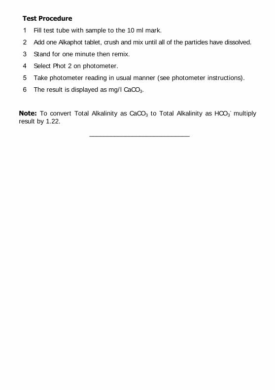
Test Procedure
1 Fill test tube with sample to the 10 ml mark.
2 Add one Alkaphot tablet, crush and mix until all of the particles have dissolved.
3 Stand for one minute then remix.
4 Select Phot 2 on photometer.
5 Take photometer reading in usual manner (see photometer instructions).
6 The result is displayed as mg/l CaCO3.
Note: To convert Total Alkalinity as CaCO3 to Total Alkalinity as HCO3- multiply
result by 1.22.
____________________________

PHOTOMETER TEST INSTRUCTIONS
_________________________________________________________________________________________
Aluminum sulphate is widely used as a coagulant in drinking water treatment. The determination of aluminum (residual alum) is usually required for the
control of alum coagulation and filtration processes at water works.
Aluminum salts are found in natural waters; levels are reported to be increasing
particularly in areas affected by acid rain. High aluminum levels can be toxic to fish and aquatic life. Aluminum determination is necessary therefore for environmental
control and for testing water used for fish farms, etc.
The YSI Aluminum test provides a simple method of measuring aluminum levels in natural and drinking waters over the range 0 - 0.5 mg/l.
Method
Aluminum reacts with Eriochrome Cyanine R indicator in slightly acid solution to
produce a pink-red colored complex. The presence of ascorbic acid eliminates
interference from iron and manganese. In the YSI Aluminum method the necessary reagents are incorporated into two test tablets. The test is simply
carried out by adding one of each tablet to a sample of the water. The first tablet acidifies the sample to bring any colloidal aluminum into solution and the
second tablet buffers the solution to provide the correct conditions for the test.
The intensity of the color produced in the test is proportional to the aluminum
concentration and is measured using a YSI Photometer.
Reagents and Equipment
YSI Aluminum No 1 Tablets
YSI Aluminum No 2 Tablets YSI 9300 or 9500 Photometer
YSI Photometer Round Test Tubes, 10 ml glass (PT 595)
Photometer Method
AUTOMATIC
WAVELENGTH SELECTION
0 – 0.5 mg/l
PHOT.3.AUTO

Sample Collection
Aluminum is readily absorbed on to the surfaces of sample containers, particularly
glass containers. To avoid loss of aluminum, collect samples in plastic bottles and
test as soon as possible after collection. Sample bottles should be acid-rinsed and thoroughly washed out with deionised water before re-use.
Test Procedure
1 Fill test tube with sample to the 10 ml mark.
2 Add one Aluminum No 1 tablet, crush and mix to dissolve.
3 Add one Aluminum No 2 tablet, crush and mix gently to dissolve. Avoid vigorous agitation.
4 Stand for five minutes to allow full color development.
5 Select Phot 3 on photometer.
6 Take photometer reading in usual manner (see photometer instructions).
7 The result is displayed as mg/l Al.
Interferences
The presence of polyphosphate or fluoride can lead to low aluminum readings.
Polyphosphate is unlikely to be present in significant quantities in normal water samples. Fluoride will only be significant for control samples from water works
where fluoridation is practised. In such cases samples should preferably be taken
before the final fluoridation stage.
For samples taken after fluoridation such as those from water distribution systems, or
for samples containing natural fluoride, the aluminium concentration should be corrected. To obtain the corrected aluminum concentration multiply the calibration
chart value by the factor (1 + 0.4 F) where F is the Fluoride concentration as mg/l F. The fluoride concentration should be determined separately by normal test procedure.
______________________________

PHOTOMETER TEST INSTRUCTIONS
_________________________________________________________________________________________
Ammonia occurs as a breakdown product of nitrogenous material in natural waters. It is also found in domestic effluents and certain industrial waste waters.
Ammonia is harmful to fish and other forms of aquatic life and the ammonia level must be carefully controlled in water used for fish farms and aquariums.
Ammonia tests are routinely applied for pollution control on effluents and waste
waters, and for the monitoring of drinking water supplies.
The YSI Ammonia Test provides a simple method of measuring ammonia
(ammoniacal nitrogen) over the range 0 - 1.0 mg/l N.
Method
The YSI Ammonia test is based on an indophenol method. Ammonia reacts with
alkaline salicylate in the presence of chlorine to form a green-blue indophenol complex. Catalysts are incorporated to ensure complete and rapid color develop-
ment. The reagents are provided in the form of two tablets for maximum convenience. The test is simply carried out by adding one of each tablet to a
sample of the water.
The intensity of the color produced in the test is proportional to the ammonia
concentration and is measured using a YSI Photometer.
Reagents and Equipment
YSI Ammonia No 1 Tablets
YSI Ammonia No 2 Tablets YSI 9300 or 9500 Photometer
Round Test Tubes, 10 ml glass (PT 595)
Photometer Method
AUTOMATIC
WAVELENGTH
SELECTION
0 – 1.0 mg/l N
PHOT.4.AUTO

Test Instructions
1 Fill test tube with sample to the 10 ml mark.
2 Add one Ammonia No 1 tablet and one Ammonia No 2 tablet, crush and mix
to dissolve.
3 Stand for 10 minutes to allow color development.
4 Select Phot 4 on photometer to measure Ammonia mg/l N or select Phot 62 on photometer to measure ammonium mg/l NH4.
5 Take photometer reading in usual manner (see photometer instructions).
Sea Water Samples
YSI Ammonia Conditioning Reagent is required when testing sea water or
brackish water samples to prevent precipitation of salts. The reagent is supplied
in a special ‘spoon pack’ to aid measuring out the powder.
Fill the test tube with sample to the 10 ml mark, and add one level spoonful of
conditioning reagent. Mix to dissolve reagent then continue the test as described in the above test instructions. If turbidity still forms in the test, repeat using two
level spoonfuls of conditioning reagent.
Notes
1 At low temperatures the rate of color development in the test may be slower.
If the sample temperature is below 20°C allow 15 minutes for the color to develop.
2 Ammonia concentrations can be expressed in a number of different ways.
The following factors may be used for the conversion of readings :-
To convert from N to NH4 multiply by 1.3.
To convert from N to NH3 multiply by 1.2.
_______________________________

PHOTOMETER TEST INSTRUCTIONS
__________________________________________________________________________________________
Bromine and bromine-release compounds are used for the disinfection of
swimming pool water, and in many other water treatment systems. Accurate measurement of the bromine residual is an essential aspect of control of these
processes.
The bromine level can be expressed in terms of the free bromine, combined
bromine or total bromine residuals. However free and combined bromine are
both considered powerful disinfectants and it is not normally necessary to differentiate between these two forms. For the majority of applications therefore
the measurement of the total residual is sufficient.
The YSI DPD bromine method provides a simple means of measuring bromine
residuals over the range 0 - 10.0 mg/l. A supplementary procedure can be used
to differentiate between free and combined bromine if desired.
Method
The YSI bromine test uses the DPD method now internationally recognised as the standard method of testing for disinfectant residuals. In the DPD method
the reagents are provided in tablet form for maximum convenience and simplicity of use.
Bromine reacts with diethyl-p-phenylene diamine (DPD) in buffered solution to
produce a pink coloration. The intensity of the color is proportional to the total bromine concentration and is measured using a YSI Photometer.
For the separate determination of free and combined bromine, a supplementary procedure using sodium nitrite is used. The nitrite destroys the free bromine in
the sample and the color produced in the DPD test then corresponds to the
combined bromine only. The free bromine content is thus obtained by difference between the total bromine and combined bromine results.
Photometer Method
AUTOMATIC
WAVELENGTH SELECTION
0 – 10.0 mg/l
PHOT.5.AUTO

Reagents and Equipment
YSI DPD No 1 Clear Tablets
YSI DPD Nitrite Tablets
YSI 9300 or 9500 Photometer Round Test Tubes, 10 ml glass (PT 595)
Separation of Bromine Residuals
The photometer is programmed for both total and free bromine. Use program
Phot 5 Total Bromine, then select the ‘Follow On’ option on screen to continue
test for program Phot 6 Free Bromine. The Free Bromine residual is calculated automatically.
Test Procedure
1 Rinse test tube with sample leaving two to three drops of sample in the tube.
2 Add one DPD No 1 tablet, crush tablet and then fill the test tube with sample to the 10 ml mark.
3 Select Phot 5 on the photometer.
4 Take photometer reading (%T) in usual manner (see photometer instructions).
5 Result displayed is Total Bromine as mg/l Br. For most purposes the test can be terminated at this stage. If it is desired to
measure free and combined bromine, select ‘Follow On’ from screen options and proceed as indicated in the following section.
Test Procedure - Free and Combined Bromine
1 Fill test tube with sample to the 10 ml mark. Add one DPD Nitrite tablet,
crush and mix to dissolve.
2 Take a second clean test tube and add two to three drops of solution from the first tube. Add one DPD No 1 tablet, crush and then add the remainder of
the solution to make up to the 10 ml mark. Mix to dissolve tablet.
3 Take photometer reading in usual manner.
4 The photometer carries out the necessary calculation and displays the Free
Bromine residual as mg/l Br.
Note
In systems containing both chlorine and bromine it is possible to differentiate
between the chlorine and bromine residuals using a supplementary procedure involving YSI DPD Glycine tablets. Details of this procedure are given on a
separate instruction sheet.

PHOTOMETER TEST INSTRUCTIONS
__________________________________________________________________________________________
Chlorine and chlorine release compounds are widely used for the disinfection of
water. When dissolved in water chlorine forms hypochlorous acid and hypochlorite
ions. Chlorine remaining in the water in this form is known as the free chlorine residual.
Chlorine does however react with ammonia and nitrogen-based species to form chloramines. These compounds are poor disinfectants and can also impart a
characteristic taste or odour to the water. It is important therefore in certain
applications to be able to distinguish between chlorine residual present as free chlorine and as chloramines.
The YSI DPD Chlorine/Chloramines method provides a simple means of measuring free chlorine (HOCI/HOCl-), monochloramine (NH2CI) and dichloramine (NHCI2).
Method
The YSI Chlorine/Chloramines test uses the DPD method. This method is
internationally recognised as the standard method of testing for chlorine and
other residuals. In the YSI method the reagents are provided in tablet form for maximum convenience and simplicity of use.
Free chlorine reacts with diethyl-p-phenylene diamine (DPD) in buffered solution to produce a pink coloration. The intensity of the color is proportional to the free
chlorine concentration. Addition of a trace amount of potassium iodide induces
further reaction with any monochloramine present. The increase in color intensity is therefore proportional to the monochloramine concentration. Subsequent addition
of excess potassium iodide causes dichloramine to react in a similar manner. The increase in color intensity is now proportional to the dichloramine concentration.
In this way it is possible to differentiate between free chlorine, monochloramine
and dichloramine residuals present in the sample. The color intensities at each stage of the test are measured using a YSI Photometer.
Photometer Method
AUTOMATIC WAVELENGTH
SELECTION
0 – 5.0 mg/l
PHOT.7.1.AUTO

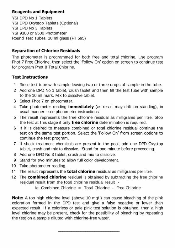
Reagents and Equipment
YSI DPD No 1 Tablets
YSI DPD No 2 Tablets
YSI DPD No 3 Tablets YSI 9300 or 9500 Photometer
Round Test Tubes, 10 ml glass (PT 595)
Separation of Chlorine Residuals
The photometer is programmed for free chlorine and for the chloramine stages.
Use program Phot 71 Free Chlorine then select ‘Follow On’ from screen options to continue test for program 72 Monochloramine and again for program 73
Dichloramine.
Test Procedure
1 Rinse test tube with sample leaving two or three drops of sample in the tube.
2 Add one DPD No 1 tablet, crush tablet and then fill test tube with sample to the 10 ml mark. Mix to dissolve tablet.
3 Select Phot 71 on photometer.
4 Take photometer reading immediately (as result may drift on standing), in
usual manner - see photometer instructions. The result represents the free chlorine residual as mg/l CI2.
5 To measure monochloramine, continue the test on the same test portion.
Select ‘Follow On’ from screen options to continue the test program.
6 Add one DPD No 2 tablet, crush and mix to dissolve.
7 Take the photometer reading immediately. The result displayed is the mono-chloramine concentration as mg/l Cl2.
8 To measure dichloramine, continue the test on the same test portion. Select
‘Follow On’ option from screen options to continue the test program.
9 Add one DPD No 3 tablet, crush and mix to dissolve. Stand for two minutes to allow full color development.
10 Take the photometer reading. The photometer displays the dichloramine
concentration as mg/l Cl2.
______________________________

PHOTOMETER TEST INSTRUCTIONS
_________________________________________________________________________________________
CHLORINE DIOXIDE
Chlorine dioxide is used for the disinfection of water in a variety of different applications. Chlorine dioxide is normally generated by reacting chlorine with
sodium chlorite solution in specially designed plant and equipment. Water treated with chlorine dioxide may therefore also contain amounts of chlorine
and chlorite. For the control of such water treatment systems it is necessary to determine and differentiate between these different residual species.
The YSI Chlorine Dioxide method provides a precise method of determining
chlorine dioxide in treated water. Supplementary procedures provide for the determination of free and combined chlorine and chlorite.
Method
Chlorine dioxide reacts with diethyl-p-phenylene diamine (DPD) in buffered
solution to produce a pink coloration. Chlorine reacts in a similar manner.
Glycine is used to prevent the reaction with chlorine so as to give specific determination of chlorine dioxide.
In the supplementary part of the test the glycine is omitted and it is then possible, by differences, to measure the free chlorine content. Subsequent addition of
potassium iodide induces a further reaction with any combined chlorine present. Continuation of the test using an acidification and neutralisation procedure produces
a further reaction and in this way the chlorite concentration can be determined.
The color intensities at each stage of the test are measured using a YSI Photometer and the concentration of each individual component are obtained by
a simple calculation. It is normal practice to express the concentration of each component in terms of the equivalent chlorine concentration.
PHOT.7.3.AUTO
Photometer Method
AUTOMATIC WAVELENGTH SELECTION 0 – 25.0 mg/l as Cl
0 – 9.5 mg/l as ClO2

Reagents and Equipment
YSI DPD No 1 Tablets
YSI DPD No 3 Tablets YSI DPD Glycine Tablets
YSI DPD Acidifying Tablets YSI DPD Neutralising Tablets
YSI 9300 or 9500 Photometer YSI Round Test Tubes, 10 ml glass (PT 595)
Test Procedure - Chlorine Dioxide
1 Rinse a clean test tube with sample, then fill with sample to the 10 ml mark.
Add one Glycine tablet, crush and mix to dissolve.
2 Decant two or three drops of Glycine treated sample into a second clean test tube. Add one DPD No 1 tablet and crush to disintegrate.
3 Add the remaining contents of the first test tube to the second test tube and mix.
4 Select Phot 7 on photometer.
5 Take photometer reading (Result G) immediately in usual manner (see photometer instructions).
6 Multiply Result G by 5 to obtain the chlorine dioxide residual in terms of mg/l
Chlorine. To obtain the chlorine dioxide residual as mg/l ClO2, multiply Result G by 1.9.
Test Procedure - Free and Combined Chlorine, and Chlorite
1 Rinse a test tube with sample leaving two or three drops. Add one DPD No 1
tablet, crush and then fill the test tube with sample to the 10 ml mark. Mix to
dissolve tablet.
2 Take the photometer reading on Phot 7 immediately (as result may drift on standing), in usual manner (Result A).
3 Continue the test by adding one DPD No 3 tablet. Crush tablet, mix to dissolve
and then stand for two minutes.
4 Take photometer reading (Result C).
5 Continue the test by adding one DPD Acidifying tablet. Crush tablet, mix to
dissolve and then stand for two minutes.
6 Add one DPD Neutralising tablet, crush and mix to dissolve.
7 Take the photometer reading (Result D).
The results of the tests, in terms of mg/l chlorine, are calculated from the observed results as follows:-
Chlorine Dioxide = 5G
Free Chlorine = A - G Combined Chlorine = C - A
Chlorite = D - (C + 4G) Total Oxidising Capacity = D

PHOTOMETER TEST INSTRUCTIONS
_________________________________________________________________________________________
Chlorine dioxide is used for the disinfection of water in a variety of different
applications. Chlorine dioxide is normally generated by reacting chlorine with sodium chlorite solution in specially designed plant and equipment. Water
treated with chlorine dioxide may therefore also contain amounts of chlorine and
chlorite. For the control of such water treatment systems it is necessary to determine and differentiate between these different residual species.
The YSI Chlorine Dioxide method provides a precise method of determining chlorine dioxide in treated water. Supplementary procedures provide for the
determination of free and combined chlorine and chlorite.
Method
Chlorine dioxide reacts with diethyl-p-phenylene diamine (DPD) in buffered solution to produce a pink coloration. Chlorine reacts in a similar manner. Glycine
is used to prevent the reaction with chlorine so as to give specific determination of
chlorine dioxide.
In the supplementary part of the test the glycine is omitted and it is then possible,
by differences, to measure the free chlorine content. Subsequent addition of potassium iodide induces a further reaction with any combined chlorine present.
Continuation of the test using an acidification and neutralization procedure produces a further reaction and in this way the chlorite concentration can be
determined.
The color intensities at each stage of the test are measured using a YSI Photometer and the concentration of each individual component are obtained by
a simple calculation. It is normal practice to express the concentration of each component in terms of the equivalent chlorine concentration.
Photometer Method
AUTOMATIC
WAVELENGTH
SELECTION
0 – 25.0 mg/l as Cl
0 – 9.5 mg/l as ClO2
PHOT.7.3.AUTO

Reagents and Equipment
YSI DPD No 1 Tablets
YSI DPD No 3 Tablets
YSI DPD Glycine Tablets YSI DPD Acidifying Tablets
YSI DPD Neutralizing Tables YSI 9300 or 9500 Photometer
Round Test Tubes, 10 ml glass (PT 595)
Test Procedures
1 Rinse a clean test tube with sample, then fill with sample to the 10 ml mark.
Add one Glycine tablet, crush and mix to dissolve.
2 Decant two or three drops of Glycine treated sample into a second clean test
tube. Add one DPD No 1 tablet and crush to disintegrate.
3 Add the remaining contents of the first test tube to the second test tube and mix.
4 Select Phot 7 on Photometer.
5 Take photometer reading (Result G) immediately (as result may drift on standing), in usual manner - see Photometer instructions.
6 Multiply Result G by 5 to obtain the chlorine dioxide residual in terms of mg/; Chlorine. To obtain the chlorine dioxide residual as mg/l ClO2, multiply
Result G by 1.9.
Test Procedures – Free and Combined Chlorine, and Chlorite
1 Rinse a test tube with sample leaving two or three drops. Add one DPD No 1
tablet, crush and then fill the test tube with sample to the 10 ml mark. Mix to dissolve tablet.
2 Take the photometer reading on Phot 7 immediately (as result may drift on standing), in usual manner (Result A).
3 Continue the test by adding one DPD No 3 tablet. Crush tablet, mix to dissolve
and then stand for two minutes.
4 Take photometer reading (Result C).
5 Continue the test by adding one DPD Acidifying tablet. Crush tablet, mix to dissolve and then stand for two minutes.
6 Add one DPD Neutralising tablet, crush and mix to dissolve.
7 Take the photometer reading (Result D).
The results of the tests, in terms of mg/l chlorine, are calculated from the
observed results as follows :
Chlorine Dioxide = 5 x G Free Chlorine = A – G Combined Chlorine = C – A Chlorite = D – (C + 4G)
Total Oxidizing Capacity = D

PHOTOMETER TEST INSTRUCTIONS
_________________________________________________________________________________________
Chlorine and chlorine-release compounds are widely used for the disinfection of
drinking water and swimming pools, for the control of micro-biological growth in cooling water, and in many other water treatment systems. Accurate
measurement of the chlorine residual is an essential aspect of the control of these chlorination processes.
The chlorine level can be expressed in terms of the free chlorine, combined
chlorine or total chlorine residuals. For the majority of applications measurement of the free chlorine residual is the most important. The YSI DPD chlorine
method provides a simple means of measuring free, combined and total chlorine residuals over the range 0 - 5 mg/l.
It is recommended that if any shock treatment compounds are known to have
been used in the treatment of the water to be tested, that a DPD Oxystop tablet be included in the test procedure as outlined below.
Method
This YSI chlorine test uses the DPD method developed by Dr A T Palin and now
internationally recognised as the standard method of testing for chlorine and other disinfectant residuals. In the YSI DPD method the reagents are provided
in tablet form for maximum convenience and simplicity of use.
Free chlorine reacts with diethyl-p-phenylene diamine (DPD) in buffered solution to produce a pink coloration. The intensity of the color is proportional to the free
chlorine concentration. Subsequent addition of excess potassium iodide induces a further reaction with any combined chlorine present. The color intensity is now
proportional to the total chlorine concentration; the increase in intensity repre-
sents the combined chlorine concentration. In this way it is possible to differentiate between free and combined chlorine present in the sample. The
color intensities are measured using a YSI Photometer.
The DPD Oxystop tablet is added after measurement for free chlorine but before
the DPD No 3 tablet. It prevents the reaction between shock treatment
chemicals and potassium iodide which would give a positive response.
Photometer Method
AUTOMATIC
WAVELENGTH SELECTION
0 – 5.0 mg/l
PHOT.7.AUTO
Reagents and Equipment
YSI DPD No 1 Tablets
YSI DPD Oxystop Tablets (Optional)
YSI DPD No 3 Tablets YSI 9300 or 9500 Photometer
Round Test Tubes, 10 ml glass (PT 595)
Separation of Chlorine Residuals
The photometer is programmed for both free and total chlorine. Use program Phot 7 Free Chlorine, then select the ‘Follow On’ option on screen to continue test
for program Phot 8 Total Chlorine.
Test Instructions
1 Rinse test tube with sample leaving two or three drops of sample in the tube.
2 Add one DPD No 1 tablet, crush tablet and then fill the test tube with sample
to the 10 ml mark. Mix to dissolve tablet.
3 Select Phot 7 on photometer.
4 Take photometer reading immediately (as result may drift on standing), in usual manner - see photometer instructions.
5 The result represents the free chlorine residual as milligrams per litre. Stop
the test at this stage if only free chlorine determination is required.
6 If it is desired to measure combined or total chlorine residual continue the
test on the same test portion. Select the ‘Follow On’ from screen options to continue the test program.
7 If shock treatment chemicals are present in the pool, add one DPD Oxystop
tablet, crush and mix to dissolve. Stand for one minute before proceeding.
8 Add one DPD No 3 tablet, crush and mix to dissolve.
9 Stand for two minutes to allow full color development.
10 Take photometer reading.
11 The result represents the total chlorine residual as milligrams per litre.
12 The combined chlorine residual is obtained by subtracting the free chlorine
residual result from the total chlorine residual result :-
ie Combined Chlorine = Total Chlorine - Free Chlorine
Note: A too high chlorine level (above 10 mg/l) can cause bleaching of the pink coloration formed in the DPD test and give a false negative or lower than
expected result. If a colorless or pale pink test solution is obtained, then a high level chlorine may be present, check for the possibility of bleaching by repeating
the test on a sample diluted with chlorine-free water.
___________________________

PHOTOMETER TEST INSTRUCTIONS
__________________________________________________________________________________________
Chlorine and chlorine release compounds are widely used for the disinfection of water. When dissolved in water chlorine forms hypochlorous acid and hypochlorite
ions. Chlorine remaining in the water in this form is known as the free chlorine
residual.
Chlorine does however react with ammonia and nitrogen-based species to form
chloramines. These compounds are poor disinfectants and can also impart a characteristic taste or odour to the water. It is important therefore in certain
applications to be able to distinguish between chlorine residual present as free
chlorine and as chloramines.
The YSI DPD Chlorine/Chloramines method provides a simple means of measuring
free chlorine (HOCl/HOCl-), monochloramine (NH2Cl) and dichloramine (NHCl2).
Method
The YSI Chlorine/Chloramines test uses the DPD method. This method is internationally recognised as the standard method of testing for chlorine and other
residuals. In the YSI method the reagents are provided in tablet form for maximum
convenience and simplicity of use.
Free chlorine reacts with diethyl-p-phenylene diamine (DPD) in buffered solution to
produce a pink coloration. The intensity of the color is proportional to the free chlorine concentration. Addition of a trace amount of potassium iodide induces
further reaction with any monochloramine present. The increase in color intensity is
therefore proportional to the monochloramine concentration. Subsequent addition of excess potassium iodide causes dichloramine to react in a similar manner. The
increase in color intensity is now proportional to the dichloramine concentration.
In this way it is possible to differentiate between free chlorine, monochloramine
and dichloramine residuals present in the sample. The color intensities at each stage of the test are measured using a YSI Photometer.
Photometer Method
AUTOMATIC WAVELENGTH
SELECTION
0 – 5.0 mg/l
PHOT.7.1.AUTO

Reagents and Equipment
YSI DPD No 1 Tablets
YSI DPD No 2 Tablets
YSI DPD No 3 Tablets YSI 9300 or 9500 Photometer
Round Test Tubes, 10 ml glass (PT 595)
Separation of Chlorine Residuals
The photometer is programmed for free chlorine and for the chloramine stages. Use program Phot 71 Free Chlorine then select ‘Follow On’ from screen options to continue
test for program 72 Monochloramine and again for program 73 Dichloramine.
Test Procedure
1 Rinse test tube with sample leaving two or three drops of sample in the tube.
2 Add one DPD No 1 tablet, crush tablet and then fill test tube with sample to
the 10 ml mark. Mix to dissolve tablet.
3 Select Phot 71 on photometer.
4 Take photometer reading immediately (as result may drift on standing), in
usual manner - see photometer instructions. The result represents the free chlorine residual as mg/l Cl2.
5 To measure monochloramine, continue the test on the same test portion.
Select ‘Follow On’ from screen options to continue the test program.
6 Add one DPD No 2 tablet, crush and mix to dissolve.
7 Take the photometer reading immediately. The result displayed is the mono-chloramine concentration as mg/l Cl2.
8 To measure dichloramine, continue the test on the same test portion. Select ‘Follow On’ option from screen options to continue the test program.
9 Add one DPD No 3 tablet, crush and mix to dissolve. Stand for two minutes
to allow full color development.
10 Take the photometer reading. The photometer displays the dichloramine
concentration as mg/l Cl2.
___________________________

PHOTOMETER TEST INSTRUCTIONS
_________________________________________________________________________________________
CHLORINE DIOXIDE
Chlorine dioxide is used for the disinfection of water in a variety of different applications. Chlorine dioxide is normally generated by reacting chlorine with
sodium chlorite solution in specially designed plant and equipment. Water treated with chlorine dioxide may therefore also contain amounts of chlorine
and chlorite. For the control of such water treatment systems it is necessary to determine and differentiate between these different residual species.
The YSI Chlorine Dioxide method provides a precise method of determining
chlorine dioxide in treated water. Supplementary procedures provide for the determination of free and combined chlorine and chlorite.
Method
Chlorine dioxide reacts with diethyl-p-phenylene diamine (DPD) in buffered solution
to produce a pink coloration. Chlorine reacts in a similar manner. Glycine is used to
prevent the reaction with chlorine so as to give specific determination of chlorine dioxide.
In the supplementary part of the test the glycine is omitted and it is then possible, by differences, to measure the free chlorine content. Subsequent addition of
potassium iodide induces a further reaction with any combined chlorine present.
Continuation of the test using an acidification and neutralisation procedure produces a further reaction and in this way the chlorite concentration can be
determined.
The color intensities at each stage of the test are measured using a YSI
Photometer and the concentration of each individual component are obtained by a simple calculation. It is normal practice to express the concentration of each
component in terms of the equivalent chlorine concentration.
PHOT.7.3.AUTO
Photometer Method
AUTOMATIC WAVELENGTH SELECTION
0 – 25.0 mg/l as Cl
0 – 9.5 mg/l as ClO2

Reagents and Equipment
YSI DPD No 1 Tablets
YSI DPD No 3 Tablets
YSI DPD Glycine Tablets YSI DPD Acidifying Tablets
YSI DPD Neutralising Tablets YSI 9300 or 9500 Photometer
YSI Round Test Tubes, 10 ml glass (PT 595)
Test Procedure - Chlorine Dioxide
1 Rinse a clean test tube with sample, then fill with sample to the 10 ml mark.
Add one Glycine tablet, crush and mix to dissolve.
2 Decant two or three drops of Glycine treated sample into a second clean test tube. Add one DPD No 1 tablet and crush to disintegrate.
3 Add the remaining contents of the first test tube to the second test tube and mix.
4 Select Phot 7 on photometer.
5 Take photometer reading (Result G) immediately in usual manner (see
photometer instructions).
6 Multiply Result G by 5 to obtain the chlorine dioxide residual in terms of mg/l
Chlorine. To obtain the chlorine dioxide residual as mg/l ClO2, multiply Result G by 1.9.
Test Procedure - Free and Combined Chlorine, and Chlorite
1 Rinse a test tube with sample leaving two or three drops. Add one DPD No 1
tablet, crush and then fill the test tube with sample to the 10 ml mark. Mix to
dissolve tablet.
2 Take the photometer reading on Phot 7 immediately (as result may drift on standing), in usual manner (Result A).
3 Continue the test by adding one DPD No 3 tablet. Crush tablet, mix to
dissolve and then stand for two minutes.
4 Take photometer reading (Result C).
5 Continue the test by adding one DPD Acidifying tablet. Crush tablet, mix to
dissolve and then stand for two minutes.
6 Add one DPD Neutralising tablet, crush and mix to dissolve.
7 Take the photometer reading (Result D).
The results of the tests, in terms of mg/l chlorine, are calculated from the
observed results as follows:-
Chlorine Dioxide = 5G Free Chlorine = A - G
Combined Chlorine = C - A Chlorite = D - (C + 4G)
Total Oxidising Capacity = D
___________________________

PHOTOMETER TEST INSTRUCTIONS
_________________________________________________________________________________________
Chlorine dioxide is used for the disinfection of water in a variety of different
applications. Chlorine dioxide is normally generated by reacting chlorine with sodium chlorite solution in specially designed plant and equipment. Water
treated with chlorine dioxide may therefore also contain amounts of chlorine and chlorite. For the control of such water treatment systems it is necessary to
determine and differentiate between these different residual species.
The YSI Chlorine Dioxide method provides a precise method of determining chlorine dioxide in treated water. Supplementary procedures provide for the
determination of free and combined chlorine and chlorite.
Method
Chlorine dioxide reacts with diethyl-p-phenylene diamine (DPD) in buffered solution to produce a pink coloration. Chlorine reacts in a similar manner. Glycine
is used to prevent the reaction with chlorine so as to give specific determination of chlorine dioxide.
In the supplementary part of the test the glycine is omitted and it is then possible,
by differences, to measure the free chlorine content. Subsequent addition of potassium iodide induces a further reaction with any combined chlorine present.
Continuation of the test using an acidification and neutralization procedure produces a further reaction and in this way the chlorite concentration can be
determined.
The color intensities at each stage of the test are measured using a YSI
Photometer and the concentration of each individual component are obtained by
a simple calculation. It is normal practice to express the concentration of each component in terms of the equivalent chlorine concentration.
Photometer Method
AUTOMATIC
WAVELENGTH SELECTION
0 – 25.0 mg/l as Cl
0 – 9.5 mg/l as ClO2
PHOT.7.3AUTO

Reagents and Equipment
YSI DPD No 1 Tablets
YSI DPD No 3 Tablets
YSI DPD Glycine Tablets YSI DPD Acidifying Tablets
YSI DPD Neutralizing Tables YSI 9300 or 9500 Photometer
Round Test Tubes, 10 ml glass (PT 595)
Test Procedures
1 Rinse a clean test tube with sample, then fill with sample to the 10 ml mark. Add one Glycine tablet, crush and mix to dissolve.
2 Decant two or three drops of Glycine treated sample into a second clean test
tube. Add one DPD No 1 tablet and crush to disintegrate.
3 Add the remaining contents of the first test tube to the second test tube and
mix.
4 Select Phot 7 on photometer.
5 Take photometer reading (Result G) immediately (as result may drift on standing), in usual manner - see photometer instructions.
6 Multiply Result G by 5 to obtain the chlorine dioxide residual in terms of
mg/; Chlorine. To obtain the chlorine dioxide residual as mg/l ClO2, multiply
Result G by 1.9.
Test Procedures – Free and Combined Chlorine, and Chlorite
1 Rinse a test tube with sample leaving two or three drops. Add one DPD No 1
tablet, crush and then fill the test tube with sample to the 10 ml mark. Mix to dissolve tablet.
2 Take the photometer reading on Phot 7 immediately (as result may drift on
standing), in usual manner (Result A).
3 Continue the test by adding one DPD No 3 tablet. Crush tablet, mix to
dissolve and then stand for two minutes.
4 Take photometer reading (Result C).
5 Continue the test by adding one DPD Acidifying tablet. Crush tablet, mix to dissolve and then stand for two minutes.
6 Add one DPD Neutralising tablet, crush and mix to dissolve.
7 Take the photometer reading (Result D).
The results of the tests, in terms of mg/l chlorine, are calculated from the observed results as follow:
Chlorine Dioxide = 5 x G
Free Chlorine = A – G Combined Chlorine = C – A
Chlorite = D – (C + 4G) Total Oxidizing Capacity = D _____________________

PHOTOMETER TEST INSTRUCTIONS
_________________________________________________________________________________________
Chlorine and chlorine-release compounds are widely used for the disinfection of drinking water and swimming pools, for the control of micro-biological growth in
cooling water, and in many other water treatment systems. Accurate
measurement of the chlorine residual is an essential aspect of the control of these chlorination processes.
The chlorine level can be expressed in terms of the free chlorine, combined
chlorine or total chlorine residuals. For the majority of applications measurement of the free chlorine residual is the most important. The YSI DPD chlorine
method provides a simple means of measuring free, combined and total chlorine residuals over the range 0 - 5 mg/l.
It is recommended that if any shock treatment compounds are known to have
been used in the treatment of the water to be tested, that a DPD Oxystop tablet be included in the test procedure as outlined below.
Method
This YSI chlorine test uses the DPD method developed by Dr A T Palin and now internationally recognised as the standard method of testing for chlorine and
other disinfectant residuals. In the YSI DPD method the reagents are provided in tablet form for maximum convenience and simplicity of use.
Free chlorine reacts with diethyl-p-phenylene diamine (DPD) in buffered solution
to produce a pink coloration. The intensity of the color is proportional to the free
chlorine concentration. Subsequent addition of excess potassium iodide induces a further reaction with any combined chlorine present. The color intensity is now
proportional to the total chlorine concentration; the increase in intensity repre-sents the combined chlorine concentration. In this way it is possible to
differentiate between free and combined chlorine present in the sample. The color intensities are measured using a YSI Photometer.
The DPD Oxystop tablet is added after measurement for free chlorine but before
the DPD No 3 tablet. It prevents the reaction between shock treatment
chemicals and potassium iodide which would give a positive response.
Photometer Method
AUTOMATIC WAVELENGTH
SELECTION
0 – 5.0 mg/l
PHOT.7.AUTO

Reagents and Equipment
YSI DPD No 1 Tablets
YSI DPD Oxystop Tablets (Optional)
YSI DPD No 3 Tablets YSI 9300 or 9500 Photometer
Round Test Tubes, 10 ml glass (PT 595)
Separation of Chlorine Residuals
The photometer is programmed for both free and total chlorine. Use program
Phot 7 Free Chlorine, then select the ‘Follow On’ option on screen to continue test for program Phot 8 Total Chlorine.
Test Instructions
1 Rinse test tube with sample leaving two or three drops of sample in the tube.
2 Add one DPD No 1 tablet, crush tablet and then fill the test tube with sample to the 10 ml mark. Mix to dissolve tablet.
3 Select Phot 7 on photometer.
4 Take photometer reading immediately (as result may drift on standing), in usual manner - see photometer instructions.
5 The result represents the free chlorine residual as milligrams per litre. Stop
the test at this stage if only free chlorine determination is required.
6 If it is desired to measure combined or total chlorine residual continue the
test on the same test portion. Select the ‘Follow On’ from screen options to continue the test program.
7 If shock treatment chemicals are present in the pool, add one DPD Oxystop tablet, crush and mix to dissolve. Stand for one minute before proceeding.
8 Add one DPD No 3 tablet, crush and mix to dissolve.
9 Stand for two minutes to allow full color development.
10 Take photometer reading.
11 The result represents the total chlorine residual as milligrams per litre.
12 The combined chlorine residual is obtained by subtracting the free chlorine residual result from the total chlorine residual result :-
ie Combined Chlorine = Total Chlorine - Free Chlorine
Note: A too high chlorine level (above 10 mg/l) can cause bleaching of the
pink coloration formed in the DPD test and give a false negative or lower than
expected result. If a colorless or pale pink test solution is obtained, then a high level chlorine may be present, check for the possibility of bleaching by
repeating the test on a sample diluted with chlorine-free water.
__________________________

PHOTOMETER TEST INSTRUCTIONS
__________________________________________________________________________________________
Chlorine and chlorine-release compounds are widely used for the disinfection of
drinking water and swimming pools, for the control of micro-biological growth in
cooling water, and in many other water treatment systems. Accurate measurement of the chlorine residual is an essential aspect of the control of these
chlorination processes.
The chlorine level can be expressed in terms of the free chlorine, combined
chlorine or total chlorine residuals. For the majority of applications measurement
of the free chlorine residual is the most important. This test method provides a simple means of measuring total chlorine residuals over the range 0 - 5 mg/l.
Method
This YSI chlorine test uses the DPD method developed by Dr A T Palin and now internationally recognized as the standard method of testing for chlorine and
other disinfectant residuals. In the YSI DPD method the reagents are provided
in tablet form for maximum convenience and simplicity of use.
Free chlorine reacts with diethyl-p-phenylene diamine (DPD) in buffered solution
to produce a pink coloration. The intensity of the color is proportional to the free chlorine concentration. Subsequent addition of excess potassium iodide induces
a further reaction with any combined chlorine present. The color intensity is now
proportional to the total chlorine concentration; the increase in intensity repre-sents the combined chlorine concentration. In this way it is possible to
differentiate between free and combined chlorine present in the sample. The color intensities are measured using a YSI Photometer.
REAGENTS AND EQUIPMENT
YSI DPD No 4 Tablets
YSI 9300 or 9500 Photometer Round Test Tubes, 10 ml glass (PT 595)
Photometer Method
AUTOMATIC
WAVELENGTH SELECTION
0 – 5.0 mg/l
PHOT.8.AUTO

Test Instructions
1 Rinse test tube with sample leaving two or three drops of sample in the tube.
2 Add one DPD No 4 tablet, crush tablet and then fill the test tube with sample
to the 10 ml mark. Mix to dissolve tablet.
3 Wait two minutes to allow full color development in the sample.
4 Select Phot 8 on photometer.
5 Take photometer reading.
6 The result represents the total chlorine as milligrams per litre.
Notes: This test will display the total of all oxidizers present in the sample. This includes chlorine, chlorine dioxide, bromine and ozone.
_____________________

PHOTOMETER TEST INSTRUCTIONS
__________________________________________________________________________________________
Chlorine and chlorine release compounds are widely used for disinfection or sterilisation of water distribution systems and pipe work, plant and equipment in
food processing and pharmaceutical factories, and similar applications. The
chlorine levels used in these applications are higher than those normally applied for the simple disinfection of water. Accurate measurement of the chlorine level
is necessary to ensure it is sufficient for the intended use. The YSI Chlorine HR test provides a simple means of measuring the total chlorine over the range 0 -
250 mg/l.
Method
The YSI Chlorine HR test is based on an iodine release method. Chlorine reacts
with potassium iodide in acid solution to release iodine which is brown in color. The reagents for the test are provided in the form of two tablets for maximum
convenience and simplicity of use.
The intensity of the color produced is proportional to the chlorine concentration
and is measured using a YSI Photometer.
Reagents and Equipment
YSI Acidifying GP Tablets
YSI Chlorine HR Tablets YSI 9300 or 9500 Photometer
Round Test Tubes, 10 ml glass (PT 595)
Photometer Method
AUTOMATIC
WAVELENGTH SELECTION
0 – 250 mg/l
PHOT.9.AUTO

Test Procedure
1 Fill test tube with sample to the 10 ml mark.
2 Add one Acidifying GP tablet and one Chlorine HR tablet. Crush tablets and
mix to dissolve. Allow any undissolved particles to settle.
3 Select Phot 9 on photometer.
4 Take photometer reading in usual manner (see photometer instructions).
5 The result is displayed as mg/l Cl.
Note: For precise determination of lower levels of chlorine, up to 5 mg/l, the YSI
Chlorine (DPD) method should be used.
__________________________

PHOTOMETER TEST INSTRUCTIONS
__________________________________________________________________________________________
Copper occurs naturally in many waters and may also result from corrosion of pipes and fittings. The presence of copper in drinking water can give rise to dis-
coloration or an astringent taste.
Chelated copper compounds are extensively used as algicides in swimming pool water, home aquariums and other waters. Electrolytic devices which generate
copper and silver ions are used in the purification of swimming pool water.
The YSI Coppercol method provides a simple means of measuring copper in
natural and treated waters over the range 0 - 5 mg/l. The test is particularly
useful since it can be used to measure specifically the concentrations of free and chelated copper present in the water.
Method
In the YSI Coppercol method copper salts are reduced to the cuprous form and
then reacted with a 2,2 Biquinoline-4,4-dicarboxylic salt to form a purple colored complex. This provides a measure of the free copper ions present in the sample. In
the second stage of the test, a decomplexing agent is introduced and this induces a
further reaction with any chelated copper compounds which might be present.
The reagents are provided in tablet form and the test is simply carried out by adding
tablets to a sample of the water. The intensity of color produced in the test is proportional to the copper concentrations and is measured using a YSI Photometer.
Reagents and Equipment
YSI Coppercol No 1 Tablets YSI Coppercol No 2 Tablets
YSI 9300 or 9500 Photometer Round Test Tubes, 10 ml glass (PT 595)
Photometer Method
AUTOMATIC WAVELENGTH
SELECTION
0 – 5.0 mg/l
PHOT.10.AUTO

Separation of Copper Residuals
The direct-reading photometer is programmed for both free and total copper. Use
program Phot 10 Free Copper, then select the ‘Follow On’ option on screen to
continue test for program Phot 11 Total Copper.
Test Procedure
1 Fill test tube with sample to the 10 ml mark.
2 Add one Coppercol No 1 tablet, crush and mix to dissolve.
3 Select Phot 10 on photometer.
4 Take photometer reading in usual manner - see photometer instructions.
5 The result represents the free copper concentration as mg/l Cu. Stop the test
at this stage if only free copper determination is required.
6 If it is desired to measure chelated or total copper continue the test on the
same test portion. Select the ‘Follow On’ from screen options to continue the test program.
7 Add one Coppercol No 2 tablet, crush and mix to dissolve.
8 Take photometer reading.
9 The result represents the Total Copper concentration as mg/l Cu.
10 The Chelated Copper concentration is obtained by subtracting the free copper concentration from the total copper concentration :-
ie Chelated Copper = Total Copper - Free Copper
__________________________

PHOTOMETER TEST INSTRUCTIONS
__________________________________________________________________________________________
Calcium hardness is caused by the presence of calcium ions in the water. Calcium salts can be readily precipitated from water and high levels of calcium
hardness tend to promote scale formation in water systems. Calcium hardness is
an important control test in industrial water systems such as boilers and steam raising plant; and for swimming pool waters.
The YSI Calcicol test provides a simple method of determining calcium hardness over the range 0 - 500 mg/l CaCO3.
Method
The YSI Calcium Hardness test is based on the Calcicol indicator reagent method. Calcium ions react specifically with Calcicol indicator in alkaline solution to give an
orange coloration. The reagent itself gives a violet color in solution. Thus at different calcium levels a distinctive range of colors from violet to orange is
produced.
The reagents for the method are provided in the form of two tablets. The test is carried out simply by adding one of each tablet to a sample of the water. The color produced is indicative of the calcium hardness and is measured using a YSI Photometer.
Reagents and Equipment
YSI Calcicol No 1 Tablets
YSI Calcicol No 2 Tablets
YSI 9300 or 9500 Photometer Round Test Tubes, 10 ml glass (PT 595)
Photometer Method
AUTOMATIC WAVELENGTH
SELECTION
0 – 500 mg/l CaCO3
PHOT.12.AUTO

Test Procedure
1 Filter sample if necessary to obtain a clear solution.
2 Fill the test tube with sample to the 10 ml mark.
3 Add one Calcicol No 1 tablet, crush and mix to dissolve.
4 Add one Calcicol No 2 tablet, crush and mix to dissolve.
5 Stand for two minutes to allow full color development.
6 Select Phot 12 on the photometer for result as mg/l CaCO3, or Phot 60 for result
as mg/l Ca.
7 Take photometer reading in the usual manner (see photometer instructions).
Interferences
1 Magnesium hardness (up to 200 mg/l as CaCO3) does not interfere with the
test.
2 Iron at levels above 10 mg/l may cause low results. Zinc above 5 mg/l may
cause high results.
3 The pH required in the test is closely controlled by a buffer mixture included in the tablet formulation. However, to avoid exceeding the buffer capacity,
strongly acid or alkaline samples should be adjusted to within the pH range 4 to 10, prior to the start of the test.
Notes
1 The expression of hardness results sometimes causes confusion. It is normal
practice to express the results of hardness tests as mg/l CaCO3 (calcium
carbonate). This is merely a convention to allow the comparison of different results and does not necessarily indicate that the hardness is present in the
water in this form.
Results may also be expressed as mg/l Ca. To convert mg/l CaCO3 to mg/l Ca
multiply by 0.4.
2 Magnesium hardness may be determined using the YSI Magnecol method (see PHOT.21), or by taking the difference between the Total Hardness (PHOT.15)
and Calcium Hardness test results.
__________________________

PHOTOMETER TEST INSTRUCTIONS
__________________________________________________________________________________________
Cyanuric acid is extensively used as a chlorine stabiliser in swimming pool
water. Cyanuric acid itself may be added to the water when the pool is first filled, or may be introduced gradually through the use of chloroisocyanurate
based chlorine donors. Swimming pool water treatment instructions generally
recommend a cyanuric acid level within the range 30 - 200 mg/l. In some countries a lower maximum level is recommended. The YSI Cyanuric Acid test
provides a simple method of measuring cyanuric acid level over the range 0 - 200 mg/l.
Method
The YSI Cyanuric Acid test is based on a single tablet reagent containing melamine and a buffer. Cyanuric acid reacts with melamine in buffered solution
to form an insoluble complex. At the cyanuric acid levels encountered in pool water, this is observed as turbidity in the test sample. The degree of turbidity is
proportional to the cyanuric acid concentration and is measured using a YSI Photometer.
Reagents and Equipment
YSI Cyanuric Acid Tablets YSI 9300 or 9500 Photometer
Round Test Tubes, 10 ml glass (PT 595) YSI Dilution Tube (PT 512)
Photometer Method
AUTOMATIC
WAVELENGTH SELECTION
0 – 200 mg/l
PHOT.13.AUTO

Test Procedure
1 Fill test tube with sample to the 10 ml mark.
2 Add one Cyanuric Acid tablet and allow to disintegrate for at least two
minutes. A cloudy solution indicates the presence of cyanuric acid.
3 Crush any remaining undissolved tablet and mix to ensure uniformity.
4 Select Phot 13 on photometer.
5 Take photometer reading in usual manner (see photometer instructions).
6 The result is displayed as mg/l.
Note
The range of the test is 0 - 200 mg/l. However when a test result of 100 mg/l or over is obtained, the following dilution technique is recommended in order to
obtain a more precise result.
1 Take a sample of pool water in a YSI Dilution Tube (PT 512), filling to the
x10 mark.
2 Make up to the 'Deionised Water' mark with deionised water, or tap water, and mix.
3 Fill a round test tube with diluted sample to the 10 ml mark. Test as per the earlier test procedure.
4 Multiply the displayed result by 10 to obtain the cyanuric acid concentration.
________________________

PHOTOMETER TEST INSTRUCTIONS
__________________________________________________________________________________________
Fluoride occurs naturally in some ground waters and is often introduced into drinking water for the prevention of tooth decay. Excessive amounts of fluoride
are however objectionable and can cause tooth discoloration.
The YSI Fluoride test provides a simple method of monitoring fluorides in
natural waters, and for the control of fluoridation plant at water works.
METHOD
Zirconyl Chloride and Eriochrome Cyanine R are reacted in acid solution to form
a red colored complex. This color is destroyed by fluoride ions to give the pale yellow color of the Eriochrome Cyanine. Differing amounts of fluoride thus
produce a range of colors from red to yellow.
The particular advantage of this method is that it is substantially free from inter-
ferences which normally beset chemical methods of fluoride testing. In particular
interference from aluminium and iron is eliminated by making the solution alkaline in the first stage of the test procedure. This breaks down any aluminium-fluoride
and iron-fluoride complexes which may be present in the water. Interference from calcium, phosphates and sulphates should not be significant at the levels normally
encountered in natural and drinking waters.
In the YSI Fluoride test two tablet reagents are used. The test is simply carried
out by adding one of each tablet to a sample of the water. The color produced
in the test is indicative of the fluoride concentration and is measured using a YSI Photometer.
REAGENTS AND EQUIPMENT
YSI Fluoride No 1 Tablets
YSI Fluoride No 2 Tablets
YSI 9300 or 9500 Photometer Round Test Tubes, 10 ml glass (PT 595)
Photometer Method
AUTOMATIC
WAVELENGTH SELECTION
0 – 1.5 mg/l
PHOT.14.AUTO

TEST PROCEDURE
1 Fill test tube with sample to the 10 ml mark.
2 Add one Fluoride No 1 tablet, crush and mix to dissolve.
3 Add one Fluoride No 2 tablet, crush and mix to dissolve.
4 Stand for five minutes to allow full color development.
5 Select Phot 14 on photometer.
6 Take photometer reading in usual manner (see photometer instructions).
7 The result is displayed as mg/l F.
____________________________

PHOTOMETER TEST INSTRUCTIONS
__________________________________________________________________________________________
Water hardness is caused by the presence of calcium and magnesium salts.
High levels of hardness prevent the formation of lather with soap, and can cause scaling in water systems - particularly boilers, heat exchangers and steam
generating plant. Hardness is an important control test in a wide variety of
applications.
The YSI Hardness test provides a simple method of checking water hardness over
the range 0 - 500 mg/l CaCO3.
Method
The YSI Hardicol test is based on a unique colorimetric method. The reagents
are provided in tablet form and the test is carried out simply by adding the appropriate tablets to a sample of the water.
Under the controlled conditions of the test calcium and magnesium ions react with Hardicol indicator to produce a purple coloration. The intensity of the color is proportional to the total hardness of the water and is measured using a YSI Photometer.
Reagents and Equipment
YSI Hardicol No 1 Tablets YSI Hardicol No 2 Tablets
YSI 9300 or 9500 Photometer Round Test Tubes, 10 ml glass (PT 595)
Photometer Method
AUTOMATIC WAVELENGTH
SELECTION
0 – 500 mg/l CaCO3
PHOT.15.AUTO

Test Procedure
1 Filter sample if necessary to obtain a clear solution.
2 Fill test tube with sample to the 10 ml mark.
3 Add one Hardicol No 1 tablet, crush and mix to dissolve.
4 Add one Hardicol No 2 tablet, crush and mix to dissolve. Ensure all particles
are completely dissolved.
5 Stand for two minutes to allow full color development.
6 Select Phot 15 on the photometer.
7 Take photometer reading in the usual manner (see photometer instructions).
8 The Total Hardness result is displayed as mg/l CaCO3.
Interferences
1 Unusually high levels of iron (above 10 mg/l) will cause low results for total
hardness.
2 The pH required in the test is closely controlled by a buffer mixture included
in the tablet formulation. However, to avoid exceeding the buffer capacity
strongly acid or alkaline samples should be adjusted to within the pH range 4 to 10, prior to the start of the test.
Notes
1 The expression of hardness results sometimes causes confusion. It is normal
practice to express the result of hardness tests as mg/l CaCO3 (calcium carbonate). This is merely a convention to allow the comparison of different
results and does not necessarily indicate that the hardness is present in the
water in this form.
2 This test measures total hardness. For the specific measurement of calcium
hardness or magnesium hardness refer to the YSI Calcicol (PHOT.12) and Magnecol (PHOT.21) tests respectively.
__________________________

PHOTOMETER TEST INSTRUCTIONS
_________________________________________________________________________________________
Hydrogen peroxide is used in various water treatment processes. In such applications
it is important to ensure that the hydrogen peroxide level is maintained within the correct range to ensure optimum operation of the water treatment process.
The YSI Hydrogen Peroxide LR test provides a simple means of measuring Hydrogen Peroxide levels over the range 0 - 2.0 mg/l.
Method
Hydrogen peroxide reacts with potassium iodide under slightly acid conditions,
and in the presence of a catalyst, to release iodine into solution. The iodine then reacts with diethyl-p-phenylene diamine (DPD) to produce a pink coloration. In
the YSI method the reagents are combined in the form of a single tablet and the
test is simply carried out by adding a tablet to a sample of the water.
The intensity of the color produced is proportional to the hydrogen peroxide concentration and is measured using a YSI Photometer.
Reagents and Equipment
YSI Hydrogen Peroxide LR Tablets
YSI 9300 or 9500 Photometer Round Test Tubes, 10 ml glass (PT 595)
Photometer Method
AUTOMATIC WAVELENGTH
SELECTION
0 – 2.0 mg/l
PHOT.16.AUTO
Test Procedure
1 Rinse test tube with sample leaving 2 to 3 drops of sample in the tube.
2 Add one Hydrogen Peroxide LR tablet, crush and then fill tube with sample to
the 10 ml mark. Mix to dissolve tablet.
3 Stand for two minutes to allow full color development.
4 Select Phot 16 on photometer.
5 Take photometer reading in usual manner (see photometer instructions).
6 The result is displayed as mg/l H2O2.
Notes
1 The sample should be free of other oxidising agents such as chlorine,
bromine, etc, as these react in a similar manner and will interfere with the test. It is unlikely that these oxidising agents will be used in conjunction with
hydrogen peroxide and, under normal circumstances, will not usually coexist in solution.
2 For measuring high levels of hydrogen peroxide used in industrial processes, use the YSI Hydrogen Peroxide HR test (see PHOT.17.).
___________________________

PHOTOMETER TEST INSTRUCTIONS
_________________________________________________________________________________________
Hydrogen peroxide is used as a bleach and oxidising agent in a number of
industrial processes. Applications include textile bleaching, commercial laundering and paper manufacturing. It is important in such processes to control
the hydrogen peroxide level within the correct range so as to achieve the
desired bleaching or oxidising effect without causing damage to the goods under treatment. Hydrogen Peroxide is also used in swimming pool water to
control algae and improve clarity.
The YSI Hydrogen Peroxide HR test provides a simple means of monitoring
hydrogen peroxide levels in water over the range 0 - 100 mg/l.
Method
Hydrogen peroxide reacts with potassium iodide under acid conditions to release
iodine which gives a yellow solution. A catalyst is used to speed up the rate of reaction. In the YSI Hydrogen Peroxide HR test the reagents are provided in the
form of two tablets. The test is simply carried out by adding one of each tablet to a sample of the water.
The intensity of the color produced in the test is proportional to the hydrogen peroxide concentration and is measured using a YSI Photometer.
Reagents and Equipment
YSI Hydrogen Peroxide HR Tablets
YSI Acidifying PT Tablets YSI 9300 or 9500 Photometer
Round Test Tubes, 10 ml glass (PT 595)
Photometer Method
AUTOMATIC WAVELENGTH
SELECTION
0 – 100 mg/l
PHOT.17.AUTO

Test Procedure
1 Fill test tube with sample to the 10 ml mark.
2 Add one Acidifying PT tablet and one Hydrogen Peroxide HR tablet. Crush tablets and mix to dissolve.
3 Select Phot 17 on photometer.
4 Take photometer reading in usual manner (see photometer instructions).
5 The result is displayed as mg/l H2O2.
Notes
1 The sample should be free of other oxidizing agents such as chlorine, bromine etc. as these react in a similar manner and will interfere with the
test. It is unlikely that these oxidizing agents will be used in conjunction with hydrogen peroxide and, under normal circumstances, will not usually coexist
in solution.
2 For measuring low levels of hydrogen peroxide, use the YSI Hydrogen Peroxide LR test (see PHOT.16.).
________________________

PHOTOMETER TEST INSTRUCTIONS
__________________________________________________________________________________________
Iron occurs widely in nature and is found in many natural and treated waters.
Iron is an objectionable constituent in both domestic and industrial water
supplies. The presence of iron affects the taste of beverages and causes unsightly staining of laundered clothes, plumbing fittings, swimming pool
surfaces and the like. The formation of insoluble iron deposits is troublesome in many industrial applications and in agricultural water uses such as drip feed
irrigation. In industry iron salts occur through corrosion of plant and equipment, and from industrial processes.
Iron is therefore an important test for the monitoring of natural and drinking waters, for corrosion control in industry and for the checking of effluents and waste waters. The YSI Iron LR test provides a simple test for the determination of low levels of iron in water over the range 0 - 1 mg/l Fe. The test responds to both ferrous and ferric iron and thus gives a measure of the total iron content of the water.
Method
The YSI Iron LR test is based on a single tablet reagent containing 3-(2-Pyridyl)-5, 6-bis(4-phenyl-sulphonic acid)-1, 2, 4-triazine (PPST) formulated with a
decomplexing/reducing agent in an acid buffer. The test is simply carried out by adding a tablet to a sample of the water under test. The decomplexing/
reducing agent breaks down weakly complexed forms of iron, and converts the
iron from the ferric to the ferrous form. The ferrous iron reacts with PPST to form a pink coloration.
The intensity of the color produced is proportional to the iron concentration and is measured using a YSI Photometer.
Photometer Method
AUTOMATIC
WAVELENGTH SELECTION
0 – 1.0 mg/l
PHOT.18.AUTO

Reagents and Equipment
YSI Iron LR Tablets
YSI 9300 or 9500 Photometer Round Test Tubes 10 ml glass (PT 595)
Test Procedure
1 Fill the test tube with sample to the 10 ml mark.
2 Add one Iron LR tablet, crush and mix to dissolve.
3 Stand for one minute to allow full color development.
4 Select Phot 18 on photometer.
5 Take photometer reading in usual manner (see photometer instructions).
6 The result is displayed as mg/l Fe.
Iron Complexes
The test color development will normally be complete within one minute.
Continued color development after this time is indicative of more strongly bound iron complexes in the water. In such cases the test solution should be stood for a
longer period, say 10 - 15 minutes, until color development is complete.
In certain industrial applications strong complexing agents are added to act as
corrosion inhibitors. Moreover, some samples may contain precipitated iron com-plexes or particles of metallic iron. These samples will require pre-treatment by a
standard laboratory procedure if it is required to determine the total iron content.
The usual method of pre-treatment is acidification-with or without boiling, dep-ending, on the nature of the sample.
To use the YSI Iron LR test after such pre-treatment procedures, add the Iron LR tablet to the acidified sample, adjust to pH 3.5 - 4.0 using ammonia or sodium
hydroxide, then take the photometer reading in the normal manner.
_________________________

PHOTOMETER TEST INSTRUCTIONS
_________________________________________________________________________________________
Iron occurs widely in nature and is found in many natural and treated waters.
Iron is an objectionable constituent in both domestic and industrial water supplies. The presence of iron affects the taste of beverages and causes
unsightly staining of laundered clothes, plumbing fittings, swimming pool
surfaces and the like. The formation of insoluble iron deposits is troublesome in many industrial applications and in agricultural water uses such as drip feed
irrigation. In industry iron salts occur through corrosion of plant and equipment, and from industrial processes.
Iron is therefore an important test for the monitoring of natural and drinking waters, for corrosion control in industry and for the checking of effluents and waste waters. The YSI Iron HR test provides a simple test for the determination of high levels of iron in water over the range 0 - 10 mg/l Fe. The test responds to both ferrous and ferric iron and thus gives a measure of the total iron content of the water.
Method
The YSI Iron HR test is based on a single tablet reagent containing an alkaline thioglycollate. The test is carried out simply by adding a tablet to a sample of
the water under test. The thioglycollate reduces ferric iron to ferrous iron and this, together with any ferrous iron already present in the sample, reacts to give
a pink coloration.
The intensity of the color produced is proportional to the iron concentration and is measured using a YSI Photometer.
Reagents and Equipment
YSI Iron HR Tablets YSI 9300 or 9500 Photometer
Round Test Tubes, 10 ml glass (PT 595)
Photometer Method
AUTOMATIC WAVELENGTH
SELECTION
0 – 10 mg/l
PHOT.19.AUTO

Test Procedure
1 Fill test tube with sample to the 10 ml mark.
2 Add one Iron HR tablet, crush and mix to dissolve.
3 Stand for one minute to allow full color development.
4 Select Phot 19 on photometer.
5 Take photometer reading in usual manner (see photometer instructions).
6 The result is displayed as mg/l Fe.
Iron Complexes
The test color development will normally be completed within one minute. Con-tinued color development after this time is indicative of more strongly bound iron
complexes in the water. In such cases the test solution should be stood for a longer period, say 10 - 15 minutes, until color development is complete.
In certain industrial applications strong complexing agents are added to act as
corrosion inhibitors. Moreover some samples may contain precipitated iron com-plexes or particles of metallic iron. These samples will require pre-treatment by a
standard laboratory procedure if it is required to determine the total iron content. The usual method of pre-treatment is acidification - with or without boiling, dep-
ending on the nature of the sample.
To use the YSI Iron HR test after such pre-treatment procedures, add the Iron HR tablet to the acidified sample, adjust to pH 6.0 - 9.0 using ammonia or
sodium hydroxide, then take the photometer reading in the normal manner.
____________________________

PHOTOMETER TEST INSTRUCTIONS
__________________________________________________________________________________________
Manganese-containing minerals occur widely and manganese salts are
commonly found in many natural waters. Manganese is an objectionable
constituent in water used for domestic purposes or industrial applications. In domestic situations, manganese will cause brown or black staining to laundry or
plumbing fittings even at very low concentrations. In process applications such as paper manufacturing or textile finishing similar staining can occur.
Manganese salts may impart an astringent taste to drinking water supplies, and in swimming pool applications can give an aesthetically displeasing brown
coloration to the water.
In most cases where manganese salts occur naturally in the water, it will be necessary to apply special methods of removal before the water can be used for domestic or industrial purposes. The YSI Manganese test provides an extremely sensitive method of measuring low concentrations of manganese for the assessment of natural waters and the control of manganese removal plant. The test measures total manganese over the range 0 - 0.030 mg/l.
Method
Manganese may occur in water in various different valency states. In the first
stage of the YSI method, manganese in lower valency states is oxidised to form permanganate by the action of an oxidising agent. In the second stage the per-
manganate formed is further reacted with leucomalachite green to form an
intense turquoise colored complex. Catalysts and inhibitors are incorporated into the tablet reagents to ensure that the color reaction proceeds correctly and
interferences are eliminated.
The intensity of color produced in the test is proportional to the total manganese concentration and is measured using a YSI Photometer.
Photometer Method
AUTOMATIC WAVELENGTH
SELECTION
0 – 0.030 mg/l
PHOT.20.AUTO

Reagents and Equipment
YSI Manganese No 1 Tablets
YSI Manganese No 2 Tablets
YSI 9300 or 9500 Photometer Round Test Tubes, 10 ml glass (PT 595)
Sample Collection
Manganese is readily absorbed onto the surfaces of sample containers. To avoid
loss of manganese test sample as soon as possible after collection.
It is important, because of the extreme sensitivity of this test, to ensure that glass-ware used for the sample collection and test procedure is scrupulously clean. For most accurate results in laboratory use it is recommended that all glassware is acid-rinsed and then thoroughly washed out with deionised water before use.
Test Procedure
1 Fill test tube with sample to the 10 ml mark (see Note 1).
2 Add one Manganese No 1 tablet, crush and mix to dissolve.
3 Add one Manganese No 2 tablet, crush and mix to dissolve then cap the tube.
4 Stand for 20 minutes to allow color development (see Note 2).
5 Select Phot 20 on photometer.
6 Take photometer reading in usual manner (see photometer instructions).
7 The result is displayed as mg/l Mn.
Notes
1 Color formation is extremely sensitive to temperature. The sample temperature should be 20° ± 1°C for optimum test results.
2 It is important to observe the standing period of 20 minutes ± 1 minute for optimum test results. Any continuing color development or color change after
this period should be ignored.
______________________

PHOTOMETER TEST INSTRUCTIONS
__________________________________________________________________________________________
Magnesium is a widely occurring natural element and is found in most water supplies. Magnesium salts contribute to the hardness of water and higher levels of magnesium will be found therefore in hard water areas. Scale formation in heating and steam raising equipment is promoted by the presence of magnesium salts in the water. Magnesium salts do however have a lower scale forming tendency than calcium salts. The YSI Magnecol test provides a simple means of measuring magnesium levels in water over the range 0 - 100 mg/l Mg.
METHOD
The YSI Magnecol test is based on a simple colorimetric procedure. Magnesium reacts with an organic reagent to produce an orange colored complex. The reagent itself is yellow and thus over the range of the test a series of colors from yellow through to orange are produced. The color produced in the test is indicative of the magnesium concentration and is measured using a YSI Photometer.
REAGENTS AND EQUIPMENT
YSI Magnecol Tablets
YSI 9300 or 9500 Photometer Round Test Tubes, 10 ml glass (PT 595)
Measuring Syringe, 1 ml (PT 361)
Photometer Method
AUTOMATIC WAVELENGTH
SELECTION
0 – 100 mg/l
PHOT.21.AUTO

TEST PROCEDURE
1 Using the measuring syringe take a 1 ml sample of the water under test.
Transfer to the round test tube and make up to the 10 ml mark with
deionised water.
2 Add one Magnecol tablet, crush and mix to dissolve.
3 Stand for five minutes to allow full color development and the slight turbidity
to clear.
4 Select Phot 21 on photometer for result as mg/l Mg. Select Phot 61 for result
as magnesium hardness, mg/l CaCO3.
5 Take photometer reading in usual manner (see photometer instructions).
Note: To convert mg/l Mg to magnesium hardness as CaCO3, multiply by 4.2.
_________________________

PHOTOMETER TEST INSTRUCTIONS
__________________________________________________________________________________________
MOLYBDATE HR
Formulations containing Molybdate are used as corrosion inhibitors in industrial
water treatment. In particular, molybdate finds application in closed recirculating systems such as hot water heating systems and chilled water systems. Molybdate-
based formulations have replaced older forms of corrosion inhibitor such as chromate.
When using molybdate treatment it is necessary to control the Molybdate
concentration within specified levels depending on the application involved. Moreover since molybdates are widely used in water treatment and in industrial
processes, molybdate is an increasingly important test for effluents and industrial discharges.
The YSI Molybdate HR test provides a simple means of measuring high levels of molybdate in industrial waters and effluents and covers the range 0 - 100 mg/l
MoO4.
Method
Molybdates react with thioglycollate under acid conditions to give a yellow
colored complex. Slightly oxidising conditions are maintained during the acidification stage in order to keep the molybdate in a fully oxidised state. Under
the conditions of the test, iron does not interfere and there is no significant
interference from other metals at levels likely to be found in industrial water systems. The reagents are provided in the form of two tablets for maximum
convenience. The test is simply carried out by adding one of each tablet to a sample of water.
The intensity of the color produced in the test is proportional to the molybdate
concentration, and is measured using a YSI Photometer.
PHOTOMETER METHOD
AUTOMATIC WAVELENGTH
SELECTION
0 – 100 mg/l MoO4
PHOT.22.AUTO

Reagents and Equipment
YSI Molybdate No 1 HR Tablets
YSI Molybdate No 2 HR Tablets
YSI 9300 or 9500 Photometer Round Test Tubes, 10 ml glass (PT 595)
Test Procedure
1 Fill round test tube with sample to the 10 ml mark.
2 Add one Molybdate No 1 HR tablet, crush and mix to dissolve.
3 Add one Molybdate No 2 HR tablet, crush and mix to dissolve.
4 Select Phot 22 on photometer.
5 Take photometer reading in usual manner (see photometer instructions).
6 The result is displayed as mg/l MoO4. Note
Molybdate concentrations can be expressed in a number of different ways. The
following factors may be used for the conversion of readings :-
To convert from MoO4 to Na2MoO4 - multiply by 1.3
To convert from MoO4 to Mo - multiply by 0.6
Interferences
The presence of Fe2+ (ferrous) or Fe3+ (ferric) iron at 5 mg/l causes the rapid
development of a red color in the test. This may be prevented by the treatment of the 10 ml sample with one YSI EDTA tablet prior to carrying out the test.
___________________________

PHOTOMETER TEST INSTRUCTIONS
__________________________________________________________________________________________
Nitrates are normally present in natural, drinking and waste waters. Nitrates
enter water supplies from the breakdown of natural vegetation, the use of chemical fertilisers in modern agriculture and from the oxidation of nitrogen
compounds in sewage effluents and industrial wastes.
Nitrate is an important control test for water supplies. Drinking waters containing excessive amounts of nitrates can cause methaemoglobinaemia in
bottle-fed infants (blue babies). The EEC has set a recommended maximum of 5.7 mg/l N (25 mg/l NO3) and an absolute maximum of 11.3 mg/l N (50 mg/l
NO3) for nitrate in drinking water.
The YSI Nitratest method provides a simple test for nitrate nitrogen over the
range 0 - 1 mg/l N. The test can however be extended to cover the range 0 - 20
mg/l by a simple dilution technique.
Method
In the YSI Nitratest method nitrate is first reduced to nitrite, the resulting nitrite is then determined by a diazonium reaction to form a reddish dye.
The reduction stage is carried out using the unique zinc-based Nitratest Powder,
and Nitratest Tablet which aids rapid flocculation after the one minute contact period. The test is conducted in a special Nitratest Tube - a graduated sample
container with hopper bottom to facilitate settlement and decanting of the sample.
The nitrite resulting from the reduction stage, is determined by reaction with
sulphanilic acid in the presence of N-(1-naphthyl)-ethy!ene diamine to form a reddish dye. The reagents are provided in a single Nitricol tablet which is simply
added to the test solution.
The intensity of the color produced in the test is proportional to the nitrate con-centration and is measured using a YSI Photometer.
Photometer Method
AUTOMATIC
WAVELENGTH SELECTION
0 – 1 mg/l N
0 – 20 mg/l N
PHOT.23.AUTO

Reagents and Equipment
YSI Nitratest Powder (Spoon Pack)
YSI Nitratest Tablets
YSI Nitricol Tablets YSI Nitratest Tube, 20 ml (PT 526)
YSI 9300 or 9500 Photometer Round Test Tubes, 10 ml (PT 595)
Test Procedure
1 Fill the Nitratest Tube with sample to the 20 ml mark.
2 Add one level spoonful of Nitratest Powder and one Nitratest tablet. Do not
crush the tablet. Replace screw cap and shake tube well for one minute.
3 Allow tube to stand for about one minute then gently invert three or four times to aid flocculation. Allow tube to stand for two minutes or longer to
ensure complete settlement.
4 Remove screw cap and wipe around the top of the tube with a clean tissue.
Carefully decant the clear solution into a round test tube, filling to the 10 ml mark.
5 Add one Nitricol tablet, crush and mix to dissolve.
6 Stand for 10 minutes to allow full color development.
7 Select Phot 23 on photometer for result as mg/l N, or Phot 63 for result as mg/l NO3.
8 Take photometer reading in usual manner (see photometer instructions).
NOTE
To convert mgll N to mgll NO3 multiply result by 4.4.
Concentrations of nitrate greater than 1.0 mg/l may be determined by diluting the original sample with deionised water. The test can be conveniently carried
out over a range 0 - 20 mg/l N as follows :-
Take a clean Nitratest Tube. Add 1 ml of sample using a pipette or graduated dropper. Fill the Nitratest Tube to the 20 ml mark with deionised water.
Continue the test procedure as given in steps 2 to 9 above. Multiply the chart reading obtained by 20 to obtain the nitrate concentration in the original sample.
Nitrite Correction
The Nitratest method will also respond to any nitrite present in the sample. In most natural and drinking waters the amount of nitrite will be small in
comparison to the nitrate concentration. If it is desired to correct for nitrite, determine nitrite concentration (as mg/l N) in the prescribed manner (see
PHOT.24.) and deduct from the nitrate concentration (as mg/l N) obtained from
the Nitratest procedure.
_______________________

PHOTOMETER TEST INSTRUCTIONS
__________________________________________________________________________________________
Nitrites are found in natural waters as an intermediate product in the nitrogen
cycle. Nitrite is harmful to fish and other forms of aquatic life and the nitrite level must be carefully controlled in water used for fish farms and aquariums.
The nitrite test is also applied for pollution control in waste waters, and for the
monitoring of drinking water.
The YSI Nitricol test provides a simple method of measuring Nitrite Nitrogen
levels over the range 0 - 0.5 mg/l N. Higher levels can be determined by diluting the sample.
Method
Nitrites in acid solution react with sulphanilic acid. The resulting diazo compound couples with N-(1-naphthyl)-ethylene diamine to form a reddish dye. The YSI
Nitricol method features a single tablet reagent containing both of these reagents in an acidic formulation. The test is simply carried out by adding a
tablet to a sample of the water under test.
The intensity of the color produced in the test is proportional to the nitrite con-
centration and is measured using a YSI Photometer.
Reagents and Equipment
YSI Nitricol Tablets
YSI 9300 or 9500 Photometer Round Test Tubes, 10 ml glass (PT 595)
Photometer Method
AUTOMATIC
WAVELENGTH
SELECTION
0 – 0.5 mg/l N
(0 – 1.6 mg/l NO2)
PHOT.24.AUTO

Test Procedure
1 Fill round test tube with sample to the 10 ml mark.
2 Add one Nitricol tablet, crush and mix to dissolve.
3 Stand for 10 minutes to allow full color development.
4 Select Phot 24 on photometer for result as mg/l N, or Phot 64 for result as mg/l NO2).
5 Take photometer reading in usual manner (see photometer instructions).
To convert from mg/l N to mg/l NO2 multiply result by 3.3.
_________________________

PHOTOMETER TEST INSTRUCTIONS
__________________________________________________________________________________________
Ozone is used for the disinfection of swimming pool water, and in many other
water treatment systems. In swimming pool water treatment ozone is normally
introduced into the circulation system and then removed prior to the re-entry of the water to the pool. In other water treatment systems an ozone residual may
be maintained in the water. In all cases accurate measurement of ozone residual is essential for the control of the system or to ensure that the ozone
has been removed.
The YSI DPD Ozone method provides a simple means of measuring ozone residuals up to a level of 2.0 mg/l. Other disinfectants such as chlorine and
bromine are frequently used in conjunction with ozone. Supplementary procedures are therefore provided for the separate determination of these
residuals.
Method
The YSI Ozone test uses the DPD method now internationally recognised as the
standard method of testing for disinfectant residuals. In the DPD method the reagents are provided in tablet form for maximum convenience and simplicity of
use.
Ozone reacts with diethyl-p-phenylene diamine (DPD) in buffered solution in the
presence of potassium iodide to produce a pink coloration. The intensity of the
color is proportional to the ozone concentration and is measured using a YSI Photometer.
For the determination of ozone in the presence of chlorine or bromine, a supple-mentary procedure using glycine is used. The glycine destroys the ozone in the
sample and the color produced in the DPD test thus corresponds to the chlorine
or bromine only. The ozone content is thus obtained by the difference between the test readings with and without glycine.
Photometer Method
AUTOMATIC WAVELENGTH
SELECTION
0 – 2.0 mg/l
PHOT.25.AUTO

Reagents and Equipment
YSI DPD No 4 Clear Tablets
YSI DPD Glycine Tablets
YSI 9300 or 9500 Photometer Round Test Tubes, 10 ml glass (PT 595)
Separation of Ozone Residuals
The photometer is programmed for both ozone and the correction procedure. Use program Phot 25 Ozone (+Chlorine), then select the ‘Follow On’ option on
screen to continue test using program Phot 26 Correction Procedure. The corrected ozone residual is calculated automatically and displayed.
Test Procedure
1 Rinse test tube with sample leaving two to three drops of sample in the tube.
2 Add one DPD No 4 tablet, crush tablet and then fill the test tube with sample
to the 10 ml mark. Mix to dissolve tablet.
3 Select Phot 25 on photometer.
4 Take photometer reading in usual manner (see photometer instructions).
5 The result represents the ozone residual as milligrams per litre.
The test may be terminated at this stage for systems treated with ozone alone. For waters containing both ozone and chlorine or bromine, a correction should be
made as indicated in the following section. Select ‘Follow On’ option on screen to
continue the test program.
Correction for Chlorine or Bromine
1 Fill a test tube with sample to the 10 ml mark. Add one DPD Glycine tablet, crush and mix to dissolve.
2 Take a second clean test tube and add two to three drops of solution from
the first tube. Add one DPD No 4 tablet, crush and then add the remainder of the solution to make up to the 10 ml mark. Mix to dissolve tablet.
3 Take photometer reading in the usual manner.
4 The photometer carries out the necessary calculation and displays the
corrected ozone residual as mg/l O3.
____________________________

PHOTOMETER TEST INSTRUCTIONS
__________________________________________________________________________________________
pH measurement is one of the tests most frequently carried out on water and aqueous solutions. The phenol red indicator method provides a simple colori-metric means of pH determination for neutral and slightly alkaline waters over the range 6.8 - 8.4 units. The Phenol Red pH test is particularly applicable to testing swimming pools and spas.
Method
The YSI Phenol Red test uses a tablet reagent containing the precise amount of phenol red indicator required for the test. Phenol red reacts in water at different pH values over the range 6.8 - 8.4 to produce a distinctive range of colors from yellow to red. The color of the test solution is indicative of the pH value and is measured using a YSI Photometer.
Phenol red tablets contain a dechlorinating agent so that the test can be carried out in water containing normal levels of chlorine or other disinfectant residuals.
Reagents and Equipment
YSI Phenol Red Clear Tablets
YSI 9300 or 9500 Photometer Round Test Tubes, 10 ml glass (PT 595)
Test Procedure
1 Fill test tube with sample to the 10 ml mark.
2 Add one Phenol Red tablet, crush and mix to dissolve.
3 Select Phot 27 on photometer.
4 Take photometer reading in usual manner (see photometer instructions).
Photometer Method
AUTOMATIC
WAVELENGTH SELECTION
6.8 – 8.4
PHOT.27.AUTO

Notes
1 The color range of the phenol red test is yellow, through orange, to red. The
formation of an intense purple coloration shows that the indicator has been
affected by high chlorine or other disinfectant residuals. In such cases the result should be disregarded.
2 Phenol red does not show any further color change at pH values below 6.8 or above 8.4. Note therefore that when such values are recorded this could
indicate that the sample has a much lower or much higher pH value.
3 Ionic strength, temperature and other water factors may have an effect on pH readings. This test has been calibrated for conditions most likely to be
encountered in a typical swimming pool at 30°C.
___________________________

PHOTOMETER TEST INSTRUCTIONS
__________________________________________________________________________________________
Phosphates are extensively used in detergent formulations and washing
powders. Phosphates also find widespread application in the food processing industry and in industrial water treatment processes. Agricultural fertilizers
normally contain phosphate minerals and phosphates also arise from the
breakdown of plant materials and in animal wastes.
Phosphates can therefore enter water courses through a variety of routes - particularly domestic and industrial effluents and run-off from agricultural land.
Phosphate is an important control test for natural and drinking waters.
Whilst phosphates are not generally considered harmful for human consumption, they do exhibit a complex effect on the natural environment. In
particular phosphates are associated with eutrophication of water and with rapid unwanted plant growth in rivers and lakes. Phosphates present in natural water
pass through into drinking water supplies.
The YSI Phosphate LR test provides a simple method of measuring phosphate levels over the range 0 - 4 mg/l PO4. For drinking water the EEC has set a guide
level of 0.5 mg/l PO4 (0.4 mg/l P2O5) and a maximum admissible concentration
of 6.7 mg/l PO4 (5 mg/l P2O5).
Method
In the YSI Phosphate LR method, the phosphate reacts under acid conditions with ammonium molybdate to form phospho-molybdic acid. This compound is
reduced by ascorbic acid to form the intensely colored ‘molybdenum blue’
complex. A catalyst is incorporated to ensure complete and rapid color develop-ment, and an inhibitor is used to prevent interference from silica. The reagents
are provided in the form of two tablets for maximum convenience. The test is simply carried out by adding one of each tablet to a sample of the water.
The intensity of the color produced in the test is proportional to the phosphate
concentration, and is measured using a YSI Photometer.
Photometer Method
AUTOMATIC
WAVELENGTH SELECTION
0 – 4.0 mg/l PO4
0 – 1.3 mg/l P
PHOT.28.AUTO

Reagents and Equipment
YSI Phosphate No 1 LR Tablets
YSI Phosphate No 2 LR Tablets
YSI 9300 or 9500 Photometer Round Test Tubes, 10 ml glass (PT 595)
Test Procedure
1 Fill test tube with sample to the 10 ml mark.
2 Add one Phosphate No 1 LR tablet, crush and mix to dissolve.
3 Add one Phosphate No 2 LR tablet, crush and mix to dissolve.
4 Stand for 10 minutes to allow full color development.
5 Select Phot 28 on photometer for result as mg/l PO4, or Phot 70 for result as
mg/l P.
6 Take photometer reading in usual manner (see photometer instructions).
Note
Phosphate concentrations can be expressed in a number of different ways. The
following factors may be used for the conversion of readings :-
To convert from PO4 to P2O5 - multiply by 0.75
To convert from PO4 to P - multiply by 0.33
_______________________

PHOTOMETER TEST INSTRUCTIONS
__________________________________________________________________________________________
Phosphates are extensively used for treating water in boilers and steam raising
plant. Phosphates are added to control the deposition of sediment and deposits
within the boiler. It is an essential part of the treatment programme to monitor the phosphate level to ensure this is within the correct range of deposition control.
The YSI Phosphate HR test provides a simple method of measuring phosphate levels in boiler waters over the range 0 - 100 mg/l PO4.
Method
The YSI Phosphate HR test is based on the vanadomolybdate method. The
distinct advantage of the YSI method is that all reagents required are provided
in the form of a test tablet. The test is carried out simply by adding a single tablet to a sample of the boiler water. A supplementary tablet may be optionally
used for the removal of Silica interference.
In the test, phosphates react with ammonium molybdate, in the presence of
ammonium vanadate, to form the yellow phosphovanadomolybdate. The
intensity of the color produced in the test is proportional to the phosphate concentration and is measured using a YSI Photometer.
Sample Collection
Samples drawn from boiler sampling points may be hot and contain particulate
matter. Prior to analysis samples should be cooled to below 25°C and filtered through a Whatman No 42 filter paper.
Reagents and Equipment
YSI Phosphate HR Tablets YSI Phosphate SR Tablets
YSI 9300 or 9500 Photometer Round Test Tubes, 10 ml glass (PT 595)
Photometer Method
AUTOMATIC WAVELENGTH
SELECTION
0 – 100 mg/l
PHOT.29.AUTO

Test Procedure
1 Fill test tube with sample to the 10 ml mark.
IN THE CASE OF SAMPLES CONTAINING SILICA (>20 mg/l SiO2) ONLY :-
2 Add one Phosphate SR tablet, crush and mix to dissolve.
3 Add one Phosphate HR tablet, crush and mix to dissolve.
4 Stand for 10 minutes to allow full color development.
5 Select Phot 29 on photometer.
6 Take photometer reading in usual manner (see photometer instructions).
7 The result is displayed as mg/l PO4.
NOTE
Phosphate SR tablets are supplied in the Phosphate HR Starter Pack (PM 114). They are subsequently available as an optional extra (AT 116) for use with Phosphate HR Replacement Reagent Packs.
_______________________

PHOTOMETER TEST INSTRUCTIONS
__________________________________________________________________________________________
Potassium is an abundant natural element. However in fresh water potassium
levels are normally low. Higher levels can be observed in brackish waters. The
guide level prescribed for drinking water supplies under the EEC Regulations is 10 mg/l.
The YSI Potassium test provides a simple means of testing potassium levels in water over the range 0 - 12.0 mg/l.
Method
The YSI Potassium test is based on a single tablet reagent containing sodium tetraphenylboron. Potassium salts react with sodium tetraphenyl-boron to form an insoluble white complex. At the potassium levels encountered in the test, this is observed as a turbidity in the test sample. The degree of turbidity is proportional to the potassium concentration and is measured using a YSI Photometer.
Reagents and Equipment
YSI Potassium K Tablets
YSI 9300 or 9500 Photometer Round Test Tubes, 10 ml glass (PT 595)
Test Procedure
1 Fill test tube with sample to the 10 ml mark.
2 Add one Potassium K tablet, crush and mix to dissolve. A cloudy solution indicates the presence of potassium.
3 Select Phot 30 on photometer.
4 Take photometer reading in usual manner (see photometer instructions).
5 The result is displayed as mg/l K.
_________________________
Photometer Method
AUTOMATIC WAVELENGTH
SELECTION
0 – 12.0 mg/l
PHOT.30.AUTO

PHOTOMETER TEST INSTRUCTIONS
__________________________________________________________________________________________
Silicon, in the form of silica, is one of the earth's most abundant elements.
Silicon is found widely in natural waters as colloidal silica or soluble silicates.
Silica and silicates do not normally cause any problems in water intended for
domestic consumption. However their presence is undesirable in water used in a
variety of industrial applications. This is because of the tendency of such water to form a hard scale on equipment. Silica and silicate containing waters are
particularly troublesome in steam generating plant such as high pressure boilers since silica scale can build up on turbine blades.
The YSI Silica LR test provides a simple means of measuring silica and silicate levels in
natural, treated and industrial waters over the range 0 - 4 mg/l SiO2.
Method
Ammonium molybdate reacts with silica under acid conditions to produce molybdosilicic acid. In the presence of a reducing agent, this compound is
reduced to form an intense blue complex. Phosphate reacts in a similar manner.
Interference by phosphate is prevented by introducing a reagent which destroys any molybdophosphoric acid which may form.
The reagents for the method are provided in tablet form and the test is carried out simply by adding tablets to a sample of water. The intensity of the color
produced in the test is proportional to the silica concentration and is measured using a YSI Photometer.
Reagents and Equipment
YSI Silica No 1 Tablets YSI Silica No 2 Tablets
YSI Silica PR Tablets YSI 9300 or 9500 Photometer
Round Test Tubes, 10 ml glass (PT 595)
Photometer Method
AUTOMATIC
WAVELENGTH SELECTION
0 – 4.0 mg/l SiO2
PHOT.31.AUTO

Test Instructions
1 Fill test tube with sample to the 10 ml mark
2 Add one Silica No 1 tablet, crush and mix to dissolve. Stand for five minutes to
allow the silica to react.
3 Add one Silica PR tablet, crush and mix to dissolve. (This stage may be
omitted if the sample is known to be completely free of phosphate).
4 Add one Silica No 2 tablet, crush and mix to dissolve. Stand for one minute
to allow full color development.
5 Select Phot 31 on photometer.
6 Take photometer reading in usual manner (see photometer instructions).
7 The result is displayed as mg/l SiO2.
Note
For testing high levels of Silica the YSI Silica HR test should be used. The range
of this test is 0 - 100 mg/l (see Test Instruction Phot 56).
___________________________

PHOTOMETER TEST INSTRUCTIONS
__________________________________________________________________________________________
Sulfates occur naturally in many waters. Sulfates are introduced into treated
waters by the use of such chemicals as aluminium sulphate, sodium bisulphate
(dry acid) and sulphuric acid. The presence of high levels of sulphate can be undesirable for a number of reasons.
In industrial waters containing sulfate localised corrosion of iron, steel and aluminum in plant and pipe work can occur through the action of sulfate-reducing
bacteria. These bacteria, which generate sulphides, cause a characteristic pitting of the metal surface.
High sulfate levels can also cause damage to concrete and cement based materials
through the formation of calcium sulfhoaluminate. This causes expansion and crumbling of the cement. It can affect concrete structures and pipes in water
distribution systems carrying sulphate-bearing ground waters; and can attack grouting in tiled swimming pools using sodium bisulphate for pH adjustment.
The YSI Sulfate test provides a simple method of measuring sulfates over the
range 0 - 200 mg/l SO4. Higher levels may be determined by diluting the sample.
Method
The YSI Sulfate test is based on a single tablet reagent containing barium chloride in a slightly acidic formulation. Barium salts react with sulphates to
form insoluble barium sulphate. At the sulfate levels encountered in the test,
this is observed as turbidity in the test sample. The degree of turbidity is proportional to the sulfate concentration and is measured using a YSI
Photometer.
Photometer Method
AUTOMATIC
WAVELENGTH SELECTION
0 – 200 mg/l
PHOT.32.AUTO

Reagents and Equipment
YSI Sulfate Turb Tablets
YSI 9300 or 9500 Photometer
Round Test Tubes, 10 ml glass (PT 595)
Test Procedure
1 Fill test tube with sample to the 10 ml mark.
2 Add one Sulfate Turb tablet, crush and mix to dissolve. A cloudy solution indicates
the presence of sulphate.
3 Stand for five minutes then mix again to ensure uniformity.
4 Select Phot 32 on photometer.
5 Take photometer reading in usual manner (see photometer instructions).
6 The result is displayed as mg/l SO4.
Caution
YSI Sulfate (Turb) tablets each contain 20 mg Barium Chloride. These tablets are
harmful if ingested. Avoid handling tablets whenever possible and wash hands after use.
_________________________

PHOTOMETER TEST INSTRUCTIONS
_________________________________________________________________________________________
Natural waters containing dissolved hydrogen sulfide and other sulfides are
found in certain parts of the world, particularly in areas having hot springs. Sul-
fides are constituents of many industrial wastes such as those from tanneries, gas plants and chemical works. Sulfides can be toxic to fish and aquatic life; and
their presence in water supplies gives rise to undesirable tastes and odours.
The YSI Sulfide Test provides a simple method of measuring total available
sulphide over the range 0 - 0.5 mg/l and is particularly applicable to natural and
drinking waters. Higher levels, such as those found in effluents and waste waters, can be determined by diluting the sample.
Method
This simplified method for the determination of sulphide is based on a reagent
containing diethyl-p-phenylene diamine (DPD) and potassium dichromate. Sul-fide reacts with this reagent in acid solution to produce a blue colored complex.
In the absence of sulphide the reagent produces a pink color. Chlorine, and
other oxidizing agents which normally react with DPD, do not interfere with the test. The reagents are provided in the form of two tablets and the test is simply
carried out by adding one of each tablet to a sample of the water.
The color produced is indicative of the sulphide concentration and is measured
using a YSI Photometer.
Reagents and Equipment
YSI Sulfide No 1 Tablets
YSI Sulfide No 2 Tablets YSI 9300 or 9500 Photometer
Round Test Tubes, 10 ml glass (PT 595)
Photometer Method
AUTOMATIC WAVELENGTH
SELECTION
0 – 0.5 mg/l
PHOT.33.AUTO

Sample Collection
To prevent loss of sulphide collect the sample carefully with a minimum of
agitation or aeration. Test the sample as soon as possible after collection.
Test Procedure
1 Fill test tube with sample to the 10 ml mark.
2 Add one Sulphide No 1 tablet and one Sulfide No 2 tablet. Crush and mix gently to dissolve the tablets. Gentle mixing is essential to avoid loss of
sulphide.
3 Stand for 10 minutes to allow full color development.
4 Select Phot 33 on photometer.
5 Take photometer reading in usual manner (see photometer instructions).
6 The result is displayed as mg/l S.
To convert from mg/l S to mg/l H2S - multiply result by 1.06
__________________________

PHOTOMETER TEST INSTRUCTIONS
__________________________________________________________________________________________
Oxygen is a major cause of corrosion in boilers and steam raising plant. Sodium
sulfite and catalysed sulphite formulations are extensively used as oxygen scavengers in boiler water treatment.
The YSI Sulfitest test provides a simple means of measuring sulfite levels for the
control of such treatments in boiler plant. The test covers the range 0 - 500 mg/l Na2SO3.
Method
The YSI Sulfitest method is based on a colorimetric procedure involving the
reduction of an indicator dye. Sulfites react with the indicator dye under
buffered conditions to destroy the original purple coloration. With increasing sulfite concentrations a range of colors from purple to colorless is produced.
An advantage of the Sulfitest method is that it does not respond to other reducing species as do traditional iodometric methods.
The degree of color loss observed in the test is proportional to the sulfite concentration and is measured using a YSI Photometer.
Reagents and Equipment
YSI Sulfitest No 1 Tablets
YSI Sulfitest No 2 Tablets YSI 9300 or 9500 Photometer
Round Test Tubes, 10 ml glass (PT 595)
Photometer Method
AUTOMATIC
WAVELENGTH SELECTION
0 – 500 mg/l Na2SO3
PHOT.34.AUTO

Test Procedure
1 Filter sample if necessary to obtain a clear solution.
2 Fill the test tube with sample to the 10 ml mark.
3 Add one Sulfitest No 1 tablet, crush and mix to dissolve.
4 Add one Sulfitest No 2 tablet, crush and mix to dissolve. Cap tube immediately.
5 Stand for two minutes to allow full color reduction to take place.
6 Select Phot 34 on the photometer.
7 Take photometer reading in the usual manner (see photometer instructions).
8 The result is displayed as mg/l Na2SO3.
NOTE
Equipment should be washed immediately after use, with a detergent if necessary, to prevent staining.
Sulfite concentrations may be expressed as mg/l SO3. To convert from mg/l Na2SO3 to mg/l SO3 multiply by 0.63.
INTERFERENCES
This test is not affected by the presence of other reducing species such as nitrite (up to 200 mg/l) ferrous iron (up to 20 mg/l) and sulfide (up to 10 mg/l); or by
the presence of polyacrylates.
Chlorine up to 250 mg/l does not cause interference. However, since sulfite and
chlorine do not normally co-exist, the test will not usually be carried out in the presence of chlorine.
Note: the test gives low results if used in the presence of tannic acid or tannin treated waters.
________________________

PHOTOMETER TEST INSTRUCTIONS
________________________________________________________________________________________
Zinc compounds are used as corrosion inhibitors in industrial cooling water
systems and similar applications. Control of the zinc level is an important aspect
of corrosion control in such systems. Zinc and zinc containing alloys are widely used in industry and zinc salts are commonly found in industrial effluents.
The YSI Zinc test provides a simple means of testing zinc levels over the range 0 - 4 mg/l and is suitable for testing cooling waters and industrial effluents, and
for the monitoring of natural and drinking waters.
Method
Zinc reacts with 5-(o-carboxyphenyl)-1-(2-hydroxy-5-sulphophenyl)-3-phenyl-
formazan (Zincon) in alkaline solution to give an intense blue color. The reagent itself is orange in solution. At different zinc levels a distinctive color range from
orange through purple to blue is produced. In the YSI Zinc test a tablet reagent containing both Zincon and an alkaline buffer is used for maximum convenience.
The test is simply carried out by adding a tablet to a sample of the water.
Samples containing high chlorine residuals are pre-treated with a special dechlorinating tablet to prevent bleaching of the test colors.
The color produced in the test is indicative of the zinc concentration and is measured using a YSI Photometer.
Copper reacts in a similar manner to zinc and a correction procedure using
EDTA is applied to those samples which contain both zinc and copper. EDTA destroys the color complex formed with zinc.
Reagents and Equipment
YSI Zinc Tablets
YSI Zinc-Dechlor Tablets YSI EDTA Tablets
YSI 9300 or 9500 Photometer
Round Test Tubes, 10 ml glass (PT 595)
Photometer Method
AUTOMATIC
WAVELENGTH SELECTION
0 – 4.0 mg/l
PHOT.35.AUTO

SEPARATION OF RESIDUALS
The photometer is programmed for both zinc and the copper correction
procedure. Use program Phot 35 Zinc (+ Copper), then select the ‘Follow On’
option on screen to continue test for program Phot 36 Corrected Zinc. The corrected zinc value is calculated automatically.
Test Procedure
1 Fill test tube to the 10 ml mark.
2 IN THE CASE OF CHLORINE CONTAINING SAMPLE ONLY :-
Add one Zinc-Dechlor tablet, crush and mix to dissolve.
3 Add one Zinc tablet, crush and mix to dissolve.
4 Allow the sample to stand for five minutes then mix again to ensure complete
dissolution of the indicator.
5 Select Phot 35 on photometer.
6 Take photometer reading in usual manner (see photometer instructions).
The result is displayed as mg/l Zn.
7 FOR COPPER CONTAINING SAMPLES ONLY :-
Continue the test on the same test portion. Select the ‘Follow On’ option on screen to continue the test program.
8 Add one EDTA tablet, crush and mix to dissolve.
9 Take photometer reading in usual manner.
10 The photometer displays the corrected zinc concentration as mg/l Zn.
_________________________

PHOTOMETER TEST INSTRUCTIONS
__________________________________________________________________________________________
The Alkalinity of water is caused by the presence of alkaline substances such as
hydroxides, carbonates, bicarbonates and, to a lesser extent, silicates and phosphates. Quantitatively alkalinity is the capacity of the water to react with
acid to a specified pH end point. The value obtained will depend on the pH
indicator used. Two measures of alkalinity are conventionally applied - Alkaphot M (Alkalinity to methyl orange) and Alkaphot P (Alkalinity to phenolphthalein).
Alkalinity is an important test parameter in a number of industrial water uses, notably in boiler water treatment. Boilers and steam raising plant are normally
operated under conditions of high alkalinity in order to minimise corrosion and
the monitoring of alkalinity is an important control test.
The YSI Alkaphot M and Alkaphot P tests provide a simple means of checking
Alkalinity M and Alkalinity P levels over the range 0 - 500 mg/l CaCO3. The tests are particularly suited to boiler and industrial waters. The alkalinities specifically
due to carbonates, bicarbonates and hydroxides can be calculated from the
various data obtained.
Method
The YSI Alkaphot M and Alkaphot P tests are both based on unique colorimetric methods. These methods offer considerable advantages over the titrimetric
methods traditionally used for measuring these parameters.
The tests are each based on the use of a single tablet reagent containing a
precisely standardised amount of acid combined with a color indicator. The tests
are simply carried out by adding the appropriate tablet to a sample of the water under test. Over the alkalinity range of each test a distinctive series of colors is
produced - from yellow through green to blue in the case of the Alkaphot M test and from colorless to purple in the case of the Alkaphot P test.
The color produced in each of the tests is indicative of the alkalinity and is
measured using a YSI Photometer.
Photometer Method
AUTOMATIC
WAVELENGTH SELECTION
0 – 500 mg/l CaCO3
PHOT.37.AUTO

Reagents and Equipment
YSI Alkaphot M Tablets
YSI Alkaphot P Tablets
YSI 9300 or 9500 Photometer Round Test Tubes, 10 ml glass (PT 595)
Test Procedure - Alkaphot M
1 Filter sample if necessary to obtain a clear solution.
2 Fill the test tube to the 10 ml mark with sample.
3 Add one Alkaphot M tablet, crush and mix. Ensure all particles are dissolved.
4 Select Phot 37 on the photometer.
5 Take photometer reading in the usual manner.
6 The result is displayed as mg/l CaCO3.
Test Procedure - Alkalinity P
1 Filter sample if necessary to obtain a clear solution.
2 Fill the test tube to the 10 ml mark with sample.
3 Add one Alkaphot P tablet, crush and mix to dissolve.
4 Stand two minutes to allow complete color development.
5 Select Phot 38 on the photometer.
6 Take photometer reading immediately in the usual manner.
7 The result is displayed as mg/l CaCO3.
Alkalinity Relationships
From the results obtained from the foregoing procedures it is possible to classify
the sample into the three main chemical forms of alkalinity present in most waters, namely hydroxides, carbonates and bicarbonates. This calculated
relationship assumes the absence of other weak forms of alkalinity and also
assumes that hydroxides and bicarbonates are not compatible in the same sample. The chemical forms of alkalinity, expressed as mg/l CaCO3 are calculated
by the following equations:-
a) If Alkalinity P = 0 b) If Alkalinity P > 0 and M > 2P
Then Bicarbonate = M Then Bicarbonate = M - 2P Carbonate = 0 Carbonate = 2P
Hydroxide = 0 Hydroxide = 0
c) If Alkalinity P > 0 and M < 2P Then Bicarbonate = 0
Carbonate = 2M - 2P Hydroxide = 2P – M
Where P and M are the results of the Alkaphot P and Alkaphot M tests respectively.

NOTE
The expression of alkalinity results sometimes causes confusion. It is normal
practice to express the result as mg/l CaCO3 (calcium carbonate). This is merely a
convention to allow the comparison of different results and does not necessarily indicate that the alkalinity is present in the water in this form. The different
chemical forms of alkalinity have been referred to in the test instructions.
________________________

PHOTOMETER TEST INSTRUCTIONS
__________________________________________________________________________________________
Iron occurs widely in nature and is found in many natural and treated waters. Iron is an objectionable constituent in both domestic and industrial water supplies. The presence of iron affects the taste of beverages and causes unsightly staining of laundered clothes, plumbing fittings, swimming pool surfaces and the like. The formation of insoluble iron deposits is troublesome in many industrial applications and in the agricultural water uses such as drip feed irrigation. In industry iron salts occur through corrosion of plant and equipment, and from industrial processes.
Iron is therefore an important test for the monitoring of natural and drinking waters, for corrosion control in industry and for the checking of effluents and waste waters. The YSI Iron MR test provides a simple test for the determination of both ferrous and ferric iron. It is capable of dissolving colloidal and particulate iron and thus gives a measure of the total iron content of the water.
Method
In the YSI Iron MR method iron is reduced to the ferrous form and then reacted with 1,10-phenanthroline to form an orange colored complex. A decomplexing agent is incorporated into the reagent system in order to break down complexed forms of iron. The test is simply carried out by adding tablet reagents to a sample of the water under test.
The intensity of the color produced is proportional to the iron concentration and is measured using a YSI Photometer.
Interference can occur in industrial waters treated with molybdate and nitrite based treatment products. A supplementary reagent can be used to prevent this interference.
Photometer Method
AUTOMATIC
WAVELENGTH
SELECTION
0 – 5.0 mg/l
PHOT.39.AUTO

Reagents and Equipment
YSI Iron MR No 1 Tablets
YSI Iron MR No 2 Tablets
YSI Citrate IR Tablets YSI 9300 or 9500 Photometer
Round Test Tubes, 10 ml glass (PT 595)
Test Procedure
1 Fill the test tube with sample to the 10 ml mark.
2 Add one Iron MR No 1 tablet, crush and mix to dissolve.
3 Add one Iron MR No 2 tablet, crush and mix to dissolve.
4 Stand for 10 minutes to allow full color development.
5 Select Phot 39 on photometer.
6 Take photometer reading in usual manner (see photometer instructions).
7 The result is displayed as mg/l Fe.
Interferences
Hardness 500 mg/l CaCO3, Silica 150 mg/l SiO2 and Copper 3 mg/l Cu do not interfere with the test. Chromium 10 mg/l may cause slightly high results.
Nitrite greater than 50 mg/l NO2 causes low results and molybdate at any
concentration causes precipitation. The pretreatment procedures described below using Citrate IR tablets remove interference from nitrite up to 500 mg/l NO2 and
molybdate up to 20 mg/l MoO4. This pretreatment does however reduce the
tolerance to chromium and is not recommended therefore for chromium containing samples.
Pretreatment Procedure using Citrate IR Tablets
Samples Containing Nitrite :-
1 Fill the test tube with sample to the 10 ml mark.
2 Add one Citrate IR tablet, crush and mix to dissolve. Ensure all particles are dissolved.
3 Continue the test as described in the test procedure from Stage 2 above but
allow the tube to stand for 15 minutes to allow full color development before taking the photometer reading.
Samples Containing Molybdate :-
1 Fill the test tube with sample to the 10 ml mark.
2 Add one Iron MR No 1 tablet, crush and mix to dissolve.
3 Add one Citrate IR tablet, crush and mix to dissolve. Ensure all particles are dissolved.
4 Continue the test as described in the test procedure from Stage 3 but allow
the tube to stand for 15 minutes to allow full color development before taking the reading.

PHOTOMETER TEST INSTRUCTIONS
__________________________________________________________________________________________
Hydrazine is used as an oxygen scavenger in high pressure boilers and steam
raising plant. Hydrazine is particularly advantageous in that it does not contribute solids to the boiler water.
The YSI Hydrazine test provides a simple means of measuring hydrazine levels in boiler feed water and boiler water over the range 0 - 0.5 mg/l.
Method
The YSI Hydrazine test uses a special reagent powder containing p-dimethyl-
aminobenzaldehyde in an acidic formulation. Hydrazine reacts with this reagent to produce a yellow coloration. The intensity of the color produced is proportional to
the hydrazine concentration and is measured using the YSI Photometer.
Reagents and Equipment
YSI Hydrazine Test Powder YSI 9300 or 9500 Photometer
Round Test Tubes, 10 ml glass (PT 595)
Scoop, 1g approx (PT 697)
Test Instructions
1 Filter sample if necessary to obtain clear solution.
2 Take two test tubes A and B.
3 Fill test tube A with sample to the 10 ml mark.
4 Fill test tube B with deionised water to the 10 ml mark.
5 To each tube add one level scoop (1g) of Hydrazine Test Powder. Mix to dissolve and cap tubes.
6 Stand for two minutes to allow full color development.
7 Select Phot 41 on photometer.
8 Take photometer reading of Tube A in usual manner (see photometer instructions).
9 Use Tube B as the Blank to set the instrument.
10 The result is displayed as mg/l N2H4.
Photometer Method
AUTOMATIC
WAVLELENGTH SELECTION
0 – 0.5 mg/l N2H4
PHOT.41.AUTO

PHOTOMETER TEST INSTRUCTIONS
__________________________________________________________________________________________
Formulations containing molybdate are used as corrosion inhibitors in industrial water treatment. In particular, low level molybdate treatment finds application in cooling systems. Molybdate based formulations have replaced older forms of corrosion inhibitors.
When using molybdate treatment it is necessary to control the molybdate concentration within specified levels depending on the application involved.
Moreover, since molybdates are widely used in water treatment and in industrial
processes, molybdate is an increasingly important test for effluents and industrial discharges.
The YSI Molybdate LR test provides a simple means of measuring low levels of molybdate in industrial waters and effluents and covers the range 0 - 20 mg/l
MoO4 (0 – 12 mg/lMo).
Method
Molybdates react with a dihydroxybenzene disulphonlc acid salt under slightly acid conditions to give a yellow colored complex. Under the conditions of the test, iron does not interfere and there is no significant interference from other metals at levels likely to be found in industrial water systems (see Notes). The reagents are provided in the form of two tablets for maximum convenience. The test is simply carried out by adding one of each tablet to a sample of water.
The intensity of the color produced in the test is proportional to the molybdate concentration and is measured using a YSI Photometer.
Reagents and Equipment
YSI Molybdate No 1 LR Tablets
YSI Molybdate No 2 LR Tablets YSI 9300 or 9500 Photometer YSI Photometer Round Test Tubes, 10 ml glass (PT 595)
Photometer Method
AUTOMATIC WAVELENGTH
SELECTION
0 – 20 mg/l MoO4
PHOT.42.AUTO

Test Procedure
1 Filter sample if necessary to obtain a clear solution.
2 Fill test tube with sample to the 10 ml mark.
3 Add one Molybdate No 1 LR tablet, crush and mix to dissolve.
4 Add one Molybdate No 2 LR tablet, crush and mix to dissolve.
5 Stand for two minutes to allow full color development.
6 Select Phot 42 on the photometer.
7 Take Photometer reading in the usual manner (see photometer instructions).
8 The result is displayed as mg/l MoO4.
Note
Molybdate concentrations can be expressed in a number of different ways. The following factors may be used for the conversion of results :-
To convert from MoO4 to Na2MoO4 - multiply by 1.3 To convert from MoO4 to Mo - multiply by 0.6.
Interferences
1 Copper 20 mg/l, zinc 20 mg/l, phosphate 100 mg/l and calcium 200 mg/l do
not interfere in this test.
2 Iron 10 mg/l and chlorine 10 mg/l cause slightly high blank readings equivalent to 0.6 mg/l Mo. However, they do not cause any interference in samples which
contain molybdate.
_________________________

PHOTOMETER TEST INSTRUCTIONS
_________________________________________________________________________________________
Nitrites and nitrite-based formulations are widely used for corrosion control in
cooling water systems. The YSI Nitriphot test provides a simple means of measuring nitrite for the control of such treatment products in cooling water.
The test covers the range 0 – 1500 mg/I NaNO2.
Method
The YSI Nitriphot method is based on a colorimetric procedure using an iodide containing reagent system. Nitrites catalyse the oxidation of the iodide to iodine under mildly acid conditions to produce a brown coloration. Over the range of the test a series of colors from colorless through yellow to brown are produced. The intensity of the color produced in the test is proportional to the nitrite concentration and is measured using a YSI Photometer.
Reagents and Equipment
YSI Nitriphot No 1 Tablets YSI Nitriphot No 2 Tablets
YSI 9300 or 9500 Photometer Round Test Tubes, 10 ml glass (PT 595)
Measuring Syringe, 1 ml (PT 361)
Photometer Method
AUTOMATIC
WAVELENGTH
SELECTION
0 – 1500 mg/l NaNO2
PHOT.43.AUTO

Test Procedure
1 Filter sample if necessary to obtain a clear solution.
2 Using the measuring syringe take 1 ml of the sample. Transfer to the test tube and make up to the 10 ml mark with deionised water.
3 Add one Nitriphot No 1 tablet, crush and mix to dissolve.
4 Add one Nitriphot No 2 tablet, crush and mix to dissolve. Cap immediately.
5 Stand for exactly two minutes to allow full color development. Ignore any further color development after this time.
6 Select Phot 43 on the photometer.
7 Take photometer reading in the usual manner (see photometer instructions).
8 The result is displayed as mg/l NaNO2.
Interferences
Chlorine in excess of 30 mg/l may give slight positive interference. However,
nitrite and chlorine are incompatible and do not normally co-exist.
The solution should be cooled to below 30°C before testing for the most accurate
analytical results.
_________________________

PHOTOMETER TEST INSTRUCTIONS
__________________________________________________________________________________________
The use of organophosphonate compounds as inhibitors in cooling systems has become widespread in recent years. It is essential to monitor the active
organophosphonate content of the cooling water to ensure the treatment is fully effective.
The YSI OP test provides a reliable means of monitoring organo-phosphonate
levels over the range 0 - 20 mg/l PO4. The test has been developed for use with commercially available organophosphonate products such as those based on
amino trimethyl phosphonic acid and hydroxyethane diphosphonic acid.
Method
In the YSI OP test, organophosphonates are first converted to orthophosphate
by a catalysed cold oxidation process. Excess oxidising agent is removed from the sample by precipitation and filtration. The orthophosphate formed in the
reaction is then determined using the 'molybdenum blue' method. The reagents for the procedure are provided in tablet form and the test is simply carried out
by adding the appropriate tablets in sequence to a diluted sample of the water.
The intensity of the blue coloration formed in the test is proportional to the
organophosphonate concentration and is determined using a YSI Photometer.
A separate correction procedure is applied to those samples known or suspected to contain orthophosphate. This compensates for the orthophosphate originally present in the sample so that a true value for organophosphonate concentration can be obtained.
Photometer Method
AUTOMATIC
WAVELENGTH SELECTION
0 – 20 mg/l PO4
PHOT.44.AUTO
Reagents and Equipment
YSI Oxidising OP Tablets
YSI OP-A Tablets
YSI OP-B Tablets YSI OP-AX Tablets
YSI 9300 or 9500 Photometer YSI Test Tube, 20 ml plastic (PT 526) Round Test Tubes, 10 ml glass (PT 595)
A filtration is required during the course of this procedure. The use of YSI Filtration Kit (PT 600) is recommended for this purpose. Alternatively, standard laboratory equipment with Whatman GF/B or equivalent papers may be used.
Correction Procedure
The photometer is programmed for both Organophosphonate and correction calibrations, and will automatically calculate the corrected organophosphonate concentration. Use program Phot 44 Organophosphonate, then select the ‘Follow On’ option on screen to continue test for program Phot 45 Correction Factor.
Sample Preparation and Dilution
1 Filter sample if necessary to obtain a clear solution.
2 Prepare x5 dilution of the sample using the YSI dilution tube.
This diluted sample is used for both the organophosphonate and correction procedures. he test calibrations take this dilution into account - it is not necessary to apply a dilution factor in the result calculation.
Test Procedure - Organophosphonate
1 Fill the plastic test tube with diluted sample to the 20 ml mark.
2 Add one Oxidising-OP tablet. Replace screw cap and shake tube until tablet dissolves.
3 Allow the tube to stand for five minutes.
4 Add one OP-A tablet. Replace screw cap and shake tube until tablet dissolves.
5 Allow the tube to stand for two minutes.
6 Filter a portion of the solution into a round glass test tube filling to the 10 ml
mark.
7 Add one OP-B tablet, crush tablet and mix to dissolve.
8 Stand for five minutes to allow full color development.
9 Select Phot 44 on photometer.
10 Take photometer reading in the usual manner (see photometer instructions).
The test may be terminated at this stage if the original sample is known not to contain orthophosphate.
Test Procedure - Correction Factor
If it is suspected that the sample contains orthophosphate, carry out the
following correction procedure. On the photometer, select the ‘Follow On’ option
on screen to continue the test program.
1 Fill a round glass test tube with diluted sample to the 10 ml mark.
2 Add one OP-AX tablet. Crush and mix to dissolve.
3 Add one OP-B tablet. Crush and mix to dissolve. 4 Stand for five minutes to allow full color development.
5 Take photometer reading in the usual manner.
6 The instrument displays the corrected organophosphonate concentration as active PO4.
Interferences
Chloride in excess of 350 mg/l will cause low results for organophosphonate. Samples containing chloride levels in excess of this value should be further diluted prior to the start of the test.
Note
The results of this test are expressed in terms of mg/l (ppm) active phosphate
content. Commercially available products are normally sold as aqueous formulations
with a given active content. To utilise the test results, regard must be paid to the active content of the product in use.
________________________
PHOTOMETER TEST INSTRUCTIONS
_________________________________________________________________________________________
The YSI Chloridol test provides a simple method for measuring chloride salt levels.
There are many applications in water technology that require determination of chlorides. These include the measurement of low levels of chloride to determine the
extent of carry-over in boiler condensates; chloride determination to assess salt build-
up in swimming pools or boiler waters; and measurement of high chloride levels for testing sea water or determining the saltiness of brackish waters. A further application
is for checking swimming pools where salt has been artificially added to simulate sea water bathing, or where this is necessary for the operation of certain types of
electrolytic hypochlorite generator.
The test can be used for measuring these widely different chloride concentrations by varying the sample size selected. The test ranges covered are 0 - 50 mg/l Cl, 0 - 500
mg/l Cl, 0 - 10,000 mg/l NaCl and 0 - 50,000 mg/l NaCl.
Method
The YSI Chloridol test is based on a tablet reagent system containing silver nitrate. Chlorides react with the silver nitrate to produce insoluble silver chloride. At the
chloride levels encountered in the test, the insoluble silver chloride is observed as
turbidity in the test sample. The degree of turbidity is proportional to the chloride concentration and is measured using a YSI Photometer.
The test is carried out under acidic and oxidising conditions so as to prevent interference from complexing agents such as EDTA and polyphosphates, and from any reducing
substances which may be present in the water. Polyacrylates do however interfere and the
test should not be used on industrial waters using polyacrylate-based treatments.
The formation of the precipitate in the Chloridol test may be subject to matrix
effects in the presence of high total dissolved solids (TDS). The 0 – 50 mg/l Cl range is calibrated only for use on softened waters and condensates, and should
not be used for other samples. The dilution step in the other ranges reduces the TDS to acceptable levels and prevents this effect.
Photometer Method
AUTOMATIC
WAVELENGTH SELECTION
0 – 50 mg/l Cl to 0 – 50,000 mg/l NaCl
PHOT.46.AUTO

Reagents and Equipment
YSI Acidifying CD Tablets
YSI Chloridol Tablets
YSI 9300 or 9500 Photometer Round Test Tubes, 10 ml glass (PT 595)
Measuring Syringe, 1 ml (PT 361) Sample Container, 100/50/10 ml plastic (PT 510)
Test Calibration
Select Program Phot 46 Range 0 – 50 mg/l Cl
or Phot 51 Range 0 – 500 mg/l Cl
or Phot 101 Range 0 – 10,000 mg/l NaCl
or Phot 102 Range 0 – 50,000 mg/l NaCl
Test Instructions
For Testing Boiler Condensate and Softened Waters ONLY
Range 0 - 50 mg/l Cl
1 Fill test tube with sample to the 10 ml mark.
For Testing Natural Waters, Drinking Water, Swimming Pools and Boiler
Waters Range: 0 - 500 mg/l Cl
Using the measuring syringe, take 1 ml of sample. Transfer to the test tube and make-up to the 10 ml mark with deionised water.
For Testing Salt Chlorinator Treated Swimming Pools
Range: 0 - 10,000 mg/l NaCl
Using the measuring syringe, take 0.5 ml of sample. Transfer to the sample
container (PT 510) then make-up to the 100 ml mark with deionised water. Cap tube and mix. Fill test tube to the 10 ml mark with solution from the
sample container.
For Testing Sea Water and Brackish Waters
Range: 0 - 50,000 mg/l NaCl
2 Using the measuring syringe, take 0.1 ml of sample. Transfer to the sample
container (PT 510) then make-up to the 100 ml mark with deionised water. Cap tube and mix. Fill test tube to the 10 ml mark with solution from the
sample container.
3 Add one Acidifying CD tablet, crush and mix to dissolve.
4 Add one Chloridol tablet, allow the tablet to disintegrate for two minutes then
crush any remaining particles and mix. A cloudy solution indicates the presence of chloride.

5 Select the appropriate program number on the photometer for the test range required.
6 Take the photometer reading in usual manner (see photometer instructions). Use the light cap whilst taking readings.
Conversion Factors
In different applications it may be conventional to express the results of chloride tests in different ways. The following conversion factors are provided for the
convenience of users:-
TO CONVERT RESULT Multiply by
From To
mg/l Cl
mg/l NaCl
mg/l CaCO3
mg/l CaCO3
1.41
0.85
________________________

PHOTOMETER TEST INSTRUCTIONS
__________________________________________________________________________________________
Pure water exhibits a light blue color when viewed in depth. This color may be
modified by the presence of organic material, typically to a yellow or brown color. An estimate of this color intensity is used as a simple means of monitoring
natural and treated water.
Method
The color of the water is determined photoelectrically using the YSI Photometer.
The sample should be filtered to remove suspended solids before analysis to determine the 'true color' due to dissolved matter.
The color of water is expressed using the platinum/cobalt color scale (Pt/Co
scale). Each unit is equivalent to the color produced by 1 mg/l platinum in the form of chloroplatinic acid in the presence of 2 mg/l cobaltous chloride
hexahydrate. These units are identical with 'Hazen' units, which have been traditionally used to express results from the visual estimation of water color.
Reagents and Equipment
YSI Color/Turbidity Set (PM 269)
YSI 9300 or 9500 Photometer
Photometer Method
AUTOMATIC WAVELENGTH
SELECTION
10 – 500 mg/l Pt (10 – 500 mg/l Hazen Units)
PHOT.47.AUTO

Test Procedure
1 Filter sample through a GF/B filter paper.
2 Fill a test tube with filtered sample to the 10 ml mark.
3 Fill a test tube with deionised water to the 10 ml mark and retain for use as
the BLANK tube.
4 Select Phot 47 on photometer.
5 Take photometer reading in usual manner (see photometer instructions) using the deionised water as the blank.
6 The result is displayed as mg/l Pt.
Note
Samples, which contain metallic impurities, dyestuffs or other industrial pollutants,
may exhibit a different color to the natural yellow-brown coloration. This test may
not be suitable for samples of this type.
________________________

PHOTOMETER TEST INSTRUCTIONS
________________________________________________________________________________________
Turbidity is an important parameter for characterizing water quality. Turbidity is
aused by the scattering of light by suspended matter such as clay, silt, finely
divided organic, and inorganic matter. A knowledge of turbidity facilitates estimation of the concentration of undissolved substances.
Method
The turbidity of the water is determined photoelectrically using the YSI Photometer. In many samples both color and turbidity will be present. In order to separate the
effect of turbidity and color, the sample is compared against a filtered portion of the
same water.
The YSI method has been calibrated against the widely recognised formazin
turbidity solutions. Turbidity is expressed in terms of Formazin Turbidity Units (FTU). These units are broadly equivalent to Jackson Turbidity Units (JTU) and
Nephelometric Turbidity Units (NTU).
Reagents and Equipment
YSI Color/Turbidity Set (PM 269) YSI 9300 or 9500 Photometer
Test Procedure
1 Filter a portion of the sample through a GF/B filter paper.
2 Fill a test tube with filtered sample and retain for use as the BLANK tube.
3 Fill a test tube with unfiltered sample to the 10 ml mark.
4 Select Phot 48 on photometer.
5 Take photometer reading in usual manner (see photometer instructions) using the filtered sample as the blank.
Note
An optional light shield is available for use with the photometer. This shield fits
over the test chamber and reduces stray light reaching the photocell. It is not
necessary to use the light shield when carrying out this test indoors or under shaded outdoor light. The use of the light shield is however recommended when
testing for turbidity under bright or variable lighting conditions.
Photometer Method AUTOMATIC WAVELENGTH SELECTION 5 – 400 Turbidity Units
PHOT.48.AUTO

PHOTOMETER TEST INSTRUCTIONS
_________________________________________________________________________________________
The presence of dissolved oxygen in water used in boilers and steam raising
plant is wholly undesirable. At high temperatures even small amounts of
dissolved oxygen render the water highly corrosive to boiler plant, the oxygen must be removed from boiler feed water by chemical treatment or by
mechanical de-aeration.
The DO/0.8/1.4 test provides a simple means of testing for dissolved oxygen in
boiler water or boiler feed water. The tests cover the range 0 - 0.8 mg/l on
most photometers and 0 – 1.4 mg/l on the Photometer 8000.
Method
Special techniques must be employed when testing for dissolved oxygen as the water sample can be readily contaminated by the oxygen in the atmosphere.
CHEMetrics Vacu-Vials self-filling reagent ampoules provide the ideal means of carrying out this test. The tip of the ampoule is dipped into the water sample
and is then broken to allow the vial to fill with water. In this way there is no
possibility of contamination from the air.
The Vacu-Vial DO/0.8 test uses a methodology based on Rhodazine D reagent.
The Rhodazine D compound in reduced form reacts with dissolved oxygen to form a bright pink complex.
The intensity of the colors formed in the tests is proportional to the dissolved
oxygen content of the water and is measured using a YSI Photometer.
Reagents and Equipment
DO Vial Reagent Set 0 - 0.8 (553) YSI 9300 or 9500 Photometer
DO test reagents are light sensitive. Store tubes in original containers and keep
the box closed when not in use.
Photometer Method
AUTOMATIC WAVELENGTH
SELECTION
0 – 0.8 mg/l / 0 – 1.4 mg/l
PHOT.49.AUTO

Test Procedure
Read the Oxygen test instructions leaflet contained in the CHEMetrics Vacu-Vials
pack. Observe these various recommendations regarding sample handling and
use of Vacu-Vials :-
1 Carry out the test in accordance with the test procedure given in the
CHEMetrics instruction leaflet. Observe the time periods given in the test instructions.
2 Select Phot 49 on the photometer. The wavelength is set automatically.
3 Use the colorless blank ampoule provided in the Starter Pack as the blank for
setting the instrument.
4 The photometer provides direct readings in mg/l O2.
Note
Note for measuring dissolved oxygen in natural waters, use the DO 15/20 test
(see instructions Phot.75).
Vacu-Vials is a registered trade mark of CHEMetrics Inc
________________________

PHOTOMETER TEST INSTRUCTIONS
_________________________________________________________________________________________
DISSOLVED OXYGEN/2
The presence of dissolved oxygen in water used in boilers and steam raising
plant is wholly undesirable. At high temperatures even small amounts of dissolved oxygen render the water highly corrosive to boiler plant, the oxygen
must be removed from boiler feedwater by chemical treatment or by mechanical de-aeration.
The DO/2.0 tests provide a simple means of testing for dissolved oxygen in
boiler water or boiler feedwater. The test covers the range and 0 - 2.0 mg/l.
Method
Special techniques must be employed when testing for dissolved oxygen as the water sample can be readily contaminated by the oxygen in the atmosphere.
CHEMetrics Vacu-Vials self-filling reagent ampoules provide the ideal means of carrying out this test. The tip of the ampoule is dipped into the water sample
and is then broken to allow the vial to fill with water. In this way there is no
possibility of contamination from the air.
The Vacu-Vial DO/2.0 test uses a reagent based on the indigo carmine method.
Indigo carmine, in its reduced form, reacts with dissolved oxygen to form a blue complex.
The intensity of the colors formed in the tests is proportional to the dissolved
oxygen content of the water and is measured using a YSI Photometer.
Reagents and Equipment
DO Vial Set DO/2.0 (503) YSI 9300 or 9500 Photometer
DO test reagents are light sensitive. Store tubes in original containers and keep the box closed when not in use.
Photometer Method
AUTOMATIC
WAVELENGTH SELECTION
0 – 2.0 mg/l
PHOT.50.AUTO

Test Procedure
Read the Oxygen test instructions leaflet contained in the CHEMetrics Vacu-Vials
pack. Observe these various recommendations regarding sample handling and
use of Vacu-Vials :-
1 Carry out the test in accordance with the test procedure given in the
CHEMetrics instruction leaflet. Observe the time periods given in the test instructions.
2 Select Phot 50 on the photometer. The wavelength is set automatically.
3 Use the colorless blank ampoule provided in the Starter Pack as the blank for setting the instrument.
4 The photometer provides direct readings in mg/l O2.
Note
Note for measuring dissolved oxygen in natural waters use the DO 15/20 test
(see instructions Phot.75).
Vacu-Vials is a registered trade mark of CHEMetrics Inc
________________________

PHOTOMETER TEST INSTRUCTIONS
_________________________________________________________________________________________
PHMB
Polyhexamethylbiguanide (PHMB) is an organic biocide used for water disinfection. PHMB-based sanitisers are widely used for the treatment of
swimming pool water. These sanitisers are typically sold under branded names,
for example Baquacil* (Zeneca), Softswim* (Biolab), Revosil* (Mareva) and Nicosil* (Nico Norge).
The YSI PHMB test provides a simple means of measuring PHMB-based sanitiser levels in swimming pool waters over the range 0 - 100 mg/l. The test is
calibrated in terms of commercially available sanitiser products which normally
contain 20% active biocide.
Method
The YSI PHMB test is based on a colorimetric method developed by Palin and now established as the standard method of testing for polyhexamethylbiguanide. In
the test the PHMB reacts with a sulphone-phthalein indicator under mildly acid conditions to form an intense blue complex. The indicator itself is yellow in color.
Thus at different PHMB levels a distinctive range of colors from yellow, through
green, to blue are produced.
In the YSI method, the reagents are combined in the form of a single tablet and
the test is simply carried out by adding a tablet to a sample of water. The intensity of the color produced is proportional to the PHMB concentration and is
measured using a YSI Photometer.
Reagents and Equipment
YSI PHMB-Phot Tablets
YSI 9300 or 9500 Photometer Round Test Tubes, 10 ml glass (PT 595)
Photometer Method
AUTOMATIC
WAVELENGTH SELECTION
0 – 100 mg/l
PHOT.52.AUTO

Test Procedure
1 Fill the test tube with sample to the 10 ml mark.
2 Add one PHMB-Phot tablet crush and mix to dissolve.
3 Select Phot 52 on photometer.
4 Take photometer reading immediately in usual manner (see photometer
instructions).
5 The result is displayed as mg/l active biocide (*all trade marks acknowledged).
______________________

PHOTOMETER TEST INSTRUCTIONS
_________________________________________________________________________________________
Nickel does not occur naturally in water but is found in many industrial waste
waters, such as those from the steel and plating industries. It is considered an
undesirable constituent of water, and hence requires close and careful monitoring. The EC maximum admissible concentration for drinking water (MAC)
is 0.05 mg/l.
The YSI Nickeltest method provides a simple test for the determination of nickel
in water over the range 0 - 10 mg/l Ni. The test responds to both Ni2+ and Ni4+ and thus gives a measure of total soluble inorganic nickel content of the water.
Method
In the YSI Nickeltest method, nickel salts are reduced to the nickelous form and then reacted with nioxime indicator to give a pink colored complex. Reagents
are included to prevent copper interference, and a complexing powder is provided to prevent iron interference.
The reagents are provided in tablet form and the test is simply carried out by adding tablets to a sample of the water. The intensity of color produced in the test is proportional to the nickel concentration and is measured using a YSI Photometer.
Reagents and Equipment
YSI Nickeltest PR Powder (Spoon Pack) YSI Nickeltest No 1 Tablets
YSI Nickeltest No 2 Tablets YSI 9300 or 9500 Photometer Round Test Tubes, 10 ml glass (PT 595)
Photometer Method
AUTOMATIC WAVELENGTH
SELECTION
0 – 10 mg/l
PHOT.53.AUTO
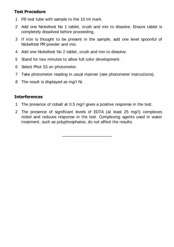
Test Procedure
1 Fill test tube with sample to the 10 ml mark.
2 Add one Nickeltest No 1 tablet, crush and mix to dissolve. Ensure tablet is
completely dissolved before proceeding.
3 If iron is thought to be present in the sample, add one level spoonful of
Nickeltest PR powder and mix.
4 Add one Nickeltest No 2 tablet, crush and mix to dissolve.
5 Stand for two minutes to allow full color development.
6 Select Phot 53 on photometer.
7 Take photometer reading in usual manner (see photometer instructions).
8 The result is displayed as mg/l Ni.
Interferences
1 The presence of cobalt at 0.5 mg/l gives a positive response in the test.
2 The presence of significant levels of EDTA (at least 25 mg/l) complexes
nickel and reduces response in the test. Complexing agents used in water treatment, such as polyphosphates, do not affect the results.
______________________

PHOTOMETER TEST INSTRUCTIONS
___________________________________________________________________________________________
Phenols and substituted phenols may occur in natural, drinking and industrial
waste waters. Phenols are not readily removed from water by conventional water treatment processes. These compounds arise typically from oil and
chemical refining, livestock dips, the breakdown of pesticides, human and animal wastes and from naturally occurring sources. Chlorination of such waters
may produce odorous and objectionable-tasting chlorophenols.
The YSI Phenoltest method provides a simple means of measuring the concentration of phenol and phenolic compounds present in water over the range
0 - 5.0 mg/l. The concentration of phenol determined in the test is due to unsubstituted and to ortho and meta substituted phenols. A proportion of para
substituted phenols will give a positive response.
Method
In the Phenoltest method, phenol and phenolic compounds react with 4-amino-
antipyrine in the presence of ferricyanide ions to form a red color. The reagents are provided in tablet form and the test is carried out simply by adding the
appropriate tablets to a sample of the water. A further tablet reagent is used to prevent interference due to metal ions.
The intensity of the red color produced in the test is proportional to the
concentration of phenolic compounds present in the sample and is measured using a YSI Photometer.
Photometer Method
AUTOMATIC
WAVELENGTH SELECTION
0 – 5.0 mg/l as Phenol
PHOT.54.AUTO

Reagents and Equipment
YSI Phenoltest No 1 Tablets
YSI Phenoltest No 2 Tablets
YSI Phenoltest PR Tablets YSI 9300 or 9500 Photometer
Round Test Tubes, 10 ml glass (PT 595)
Test Procedure
1 Fill round test tube to the 10 ml mark with sample.
2 In the case of samples known to contain copper, zinc, iron or manganese
ions, add one Phenoltest PR tablet. Crush and mix to dissolve.
3 Add one Phenoltest No 1 tablet, crush and mix to dissolve.
4 Add one Phenoltest No 2 tablet, crush and mix to dissolve.
5 Stand for 10 minutes to allow full color development.
6 Select Phot 54 on the photometer.
7 Take photometer reading in the usual manner (see photometer instructions).
8 The result is displayed as mg/l C6H5OH.
Interferences
1 Use of the Phenoltest PR tablet will prevent interference from metal ions up
to a concentration of 350 mg/l. The test is unaffected by free chlorine in the
sample up to 10 mg/l.
2 Low results may be obtained in samples containing more than 150 mg/l
alkalinity (as CaCO3), 10 mg/l sulphite or 2 mg/l sulphide. Certain organic keto-enol compounds may cause high results. In the case of known or
suspected interferences, then the sample should be pre-treated in accordance with standard analytical procedures.
_________________________

PHOTOMETER TEST INSTRUCTIONS
_________________________________________________________________________________________
Chromium may be present in certain industrial waste waters, such as those from
the tanning, plating and coating industries. Chromium may occur in hexavalent form as chromates and dichromates, or in trivalent form as chromium salts. In
water supplies hexavalent chromium is a particularly objectionable constituent.
Trivalent chromium, although relatively inert, is also regarded as undesirable.
The YSI Chromicol test provides a means of measuring chromium over the
range 0 - 1.0 mg/l. The test is particularly useful since it can be used to differentiate between the concentrations of trivalent (CrIII) and hexavalent (CrVI)
chromium present.
Method
In the YSI Chromicol method, hexavalent chromium salts in acidic conditions
react with diphenylcarbazide to give a purple colored complex. This provides a measure of the hexavalent chromium (CrVI) present in the sample. The reagents
are provided in tablet form and the test is simply carried out by adding tablets to a sample of the water.
To determine total chromium (CrIII) plus (CrVI) a fresh sample of the solution is
oxidised using a powder reagent to convert the trivalent chromium to the hexavalent form. The test is then repeated to give a measure of the total
soluble chromium content of the water. The difference between the two readings gives a measure of trivalent chromium
The intensity of color produced in the tests is proportional to the chromium
concentrations and is measured using a YSI Photometer.
Photometer Method
AUTOMATIC
WAVELENGTH SELECTION
0 – 1.0 mg/l
PHOT.55.AUTO

Reagents and Equipment
For Hexavalent Chromium :-
YSI Chromicol No 1 Tablets
YSI Chromicol No 2 Tablets YSI 9300 or 9500 Photometer
YSI Test Tubes, 10 ml glass (PT 595)
For Trivalent and Total Chromium :-
YSI Chromicol CR Reagent (Spoon Pack)
YSI Pretreatment Tube, 20 ml plastic (PT 526) Filtration Kit, 0.45µm (PT 601)
Chromicol CR Reagent and the Pretreatment Tube are additional items required in the tests for total and trivalent chromium. These items are available as a
supplementary pack (AT 283) for use in conjunction with standard Chromicol reagent packs (PM 281 and AP 281).
A filtration is required during the course of the procedure for total and trivalent
chromium. The use of YSI Filtration Kit (PT 601) is recommended for this purpose. Alternatively, standard laboratory equipment with Whatman 0.45µm or
equivalent membrane filters may be used.
Test Procedure - Hexavalent Chromium
1 Fill round test tube to the 10 ml mark.
2 Add one Chromicol No 1 tablet, crush and mix to dissolve.
3 Add one Chromicol No 2 tablet, crush and mix to dissolve.
4 Stand for 10 minutes without disturbing the solution to allow full color
development and to enable any undissolved particles to settle.
5 Select Phot 55 on the photometer.
6 Take photometer reading in the usual manner (see photometer instructions). (Result A).
7 The result represents the hexavalent chromium concentration (chromates and dichromates) as mg/l Cr. Stop the test at this stage if only hexavalent
chromium determination is required.

Test Procedure - Total Chromium
1 Fill the pretreatment tube with sample to the 20 ml mark.
2 Add one level spoonful of Chromicol CR powder. Replace screw cap and
shake tube well for two minutes.
3 Allow tube to stand for two minutes.
4 Filter a portion of the solution dropwise into a round glass test tube. Discard the first few drops and then fill to the 10 ml mark.
5 Add one Chromicol No 1 tablet, crush and mix to dissolve.
6 Add one Chromicol No 2 tablet, crush and mix to dissolve.
7 Stand for 10 minutes without disturbing the solution to allow full color
development and to enable any undissolved particles to settle.
8 Select Phot 100 on photometer.
9 Take photometer reading in usual manner (see photometer instructions).
10 The result represents the total soluble chromium concentration (trivalent and
hexavalent) as mg/l Cr (Result B).
11 The trivalent Chromium (CrIII) concentration is obtained by subtracting Result
A from Result B :-
Trivalent Chromium = Result B - Result A
Interferences
Levels of dissolved iron above 1 mg/l cause low results for chromium. To increase the tolerance, repeat the test using two Chromicol No 1 tablets and one
Chromicol No 2 tablet. Tannin causes complexation which prevents a response in the test.
________________________

PHOTOMETER TEST INSTRUCTIONS
_________________________________________________________________________________________
Silicon, in the form of silica, is one of the earth's most abundant elements. Silicon is found widely in natural waters as colloidal silica or soluble silicates.
Silica and silicates do not normally cause any problems in water intended for domestic consumption. However, their presence is undesirable in water used in
a variety of industrial applications. This is because of the tendency of such
water to form a hard scale on equipment. Silica and silicate containing waters are particularly troublesome in steam generating plant such as high pressure
boilers since silica scale can build up on turbine blades.
Formulations containing silicate are used in industrial water treatment, as it is
necessary to control the silicate within specified levels.
The YSI Silica test provides a simple means of measuring silica and silicate levels in
natural, treated, industrial and cooling waters over the range 0 - 150 mg/l SiO2.
Method
Sodium molybdate reacts with silica under acid conditions to produce molybdosilicic
acid. Phosphate reacts in a similar manner. Interference by phosphate is prevented by introducing a reagent that destroys any molybdo-phosphoric acid
which may form.
The reagents for the method are provided in tablet form and the test is carried out simply by adding tablets to a sample of water. The intensity of the color
produced in the test is proportional to the silica concentration and is measured using a YSI Photometer.
Reagents and Equipment
YSI Silica HR No 1 Tablets
YSI Silica HR No 2 Tablets
YSI Silica PR Tablets YSI 9300 or 9500 Photometer
Round Test Tubes, 10 ml glass (PT 595)
Photometer Method
AUTOMATIC
WAVELENGTH SELECTION
0 – 150 mg/l SiO2
PHOT.56.AUTO

Test Procedure
1 Fill the test tube with sample to the 10 ml mark.
2 Add one Silica No 1 tablet, crush and mix to dissolve.
3 Add one Silica No 2 tablet, crush and mix to dissolve. Stand for 10 minutes
to allow full color development.
4 Add one Silica PR tablet, crush and mix to dissolve. Stand for two minutes. (This stage may be omitted if the sample is known to be completely free of
phosphate and chlorine).
5 Select Phot 56 on photometer.
6 Take photometer reading in usual manner (see photometer instructions).
7 The result is displayed as mg/l SiO2.
________________________

PHOTOMETER TEST INSTRUCTIONS
__________________________________________________________________________________________
Chlorine dioxide is increasingly being chosen ahead of chlorine for use in many
applications where it is believed to have several advantages.
Chlorine dioxide is used in water disinfection, where its ability to disrupt biofilm in
pipe work makes it useful against certain waterborne micro organisms such as Legionella. Chlorine dioxide is also used in the food industry for control of micro
organisms in fruit washing and is popular in the pulp and paper industry as a
bleaching agent. The USEPA has rated chlorine dioxide as the best available technology for paper pulp bleaching due to its low environmental impact.
Chlorine dioxide may be generated on-site either electrolytically or by reacting chlorine with sodium chlorite solution. Water treated with chlorine dioxide may
therefore also contain amounts of chlorine and chlorite. For the control of water
treatment systems it is necessary to determine chlorine dioxide in the presence of these other residuals.
The YSI Chlorine Dioxide method provides a specific method of determining chlorine dioxide in treated water, in the presence of free and combined chlorine
and chlorite.
Method
In the YSI Chlorine Dioxide test, Lissamine Green B is bleached under alkaline
conditions by chlorine dioxide. An ammonium salt is used to prevent any interference by chlorine. This method can determine chlorine dioxide accurately
in the presence of free and complexed chlorine, chlorite, chlorate, ozone, bromine and permanganate.
Reagents and Equipment
YSI Chlordiox Buffer Tablets YSI Chlordiox LR Tablets
YSI 9300 or 9500 Photometer YSI Round Test Tubes, 10 ml glass (PT 595)
Photometer Method
AUTOMATIC WAVELENGTH
SELECTION
0 – 2.5 mg/l
PHOT.74.AUTO

Important Note
Chlorine dioxide is extremely volatile and can be lost from solution very easily.
Extreme care must be taken when extracting and dispensing samples to minimise
any loss from solution to ensure accurate measurement. When pouring the sample into a test tube, it is recommended that this is done by holding the tube
at a slight angle and pouring slowly and gently down the side of the tube to minimise any splashing and turbulence which may cause loss of chlorine dioxide
vapour.
Test Procedure - Chlorine Dioxide
1 Rinse a clean test tube with sample leaving a few drops in the tube.
2 Add one Chlordiox Buffer tablet and one Chlordiox LR tablet, crush and mix both together in the small volume of sample left in the tube to produce an
even mixture of well crushed material.
3 Rinse and fill another clean test tube with sample to the 10 ml mark and
slowly pour this into the tube containing the crushed tablets.
4 Mix the tube contents with a crushing rod to ensure complete dissolution of the tablet material.
5 Stand for one minute to allow the chlorine dioxide to react with the indicator.
6 Select Phot 74 on photometer.
7 Take photometer reading in usual manner (see photometer instructions). This
result represents the chlorine dioxide residual in terms of mg/l ClO2.
Note - to obtain the chlorine dioxide residual as mg/l Cl2 divide the result by 1.9.
Interferences
Studies of the effect of expected levels of common species which may be present
in chlorine dioxide containing waters were undertaken to determine if these would detrimentally affect the results of the test. These included other chlorine
compounds and oxidising agents, metal ions, hardness, alkalinity, nitrate,
phosphate and sulphate. No interference effect was observed.
Temperature Effect
The method is calibrated for use at 15 – 25°C - lower temperatures will cause a
slightly high bias to results. For accurate results, equilibrate a full glass bottle of
sample, with no headspace, to room temperature for analysis.
___________________________

PHOTOMETER TEST INSTRUCTIONS
_________________________________________________________________________________________
Chlorine dioxide is increasingly being chosen ahead of chlorine for use in many applications where it is believed to have several advantages.
Chlorine dioxide is used in water disinfection, where its ability to disrupt biofilm in
pipe work makes it useful against certain waterborne micro organisms such as Legionella. Chlorine dioxide is also used in the food industry for control of micro
organisms in fruit washing and is popular in the pulp and paper industry as a
bleaching agent. The USEPA has rated chlorine dioxide as the best available technology for paper pulp bleaching due to its low environmental impact.
Chlorine dioxide may be generated on-site either electrolytically or by reacting chlorine with sodium chlorite solution. Water treated with chlorine dioxide may
therefore also contain amounts of chlorine and chlorite. For the control of water
treatment systems it is necessary to determine chlorine dioxide in the presence of these other residuals.
The YSI Chlorine Dioxide method provides a specific method of determining chlorine dioxide in treated water, in the presence of free and combined chlorine and chlorite.
Method
In the YSI Chlorine Dioxide test, Lissamine Green B is bleached under alkaline
conditions by chlorine dioxide. An ammonium salt is used to prevent any
interference by chlorine. This method can determine chlorine dioxide accurately in the presence of free and complexed chlorine, chlorite, chlorate, ozone,
bromine and permanganate.
Reagents and Equipment
YSI Chlordiox Buffer Tablets
YSI Chlordiox HR Tablets YSI 9300 or 9500 Photometer
YSI Round Test Tubes, 10 ml glass (PT 595)
Photometer Method
AUTOMATIC
WAVELENGTH
SELECTION
0 – 20 mg/l
PHOT.76.AUTO

Important Note
Chlorine dioxide is extremely volatile and can be lost from solution very easily.
Extreme care must be taken when extracting and dispensing samples to minimise
any loss from solution to ensure accurate measurement. When pouring the sample into a test tube, it is recommended that this is done by holding the tube at a slight
angle and pouring slowly and gently down the side of the tube to minimise any splashing and turbulence which may cause loss of chlorine dioxide vapour.
Test Procedure - Chlorine Dioxide
1 Rinse a clean test tube with sample leaving a few drops in the tube.
2 Add one Chlordiox Buffer tablet and one Chlordiox HR tablet, crush and mix
both together in the small volume of sample left in the tube to produce an even mixture of well crushed material.
3 Rinse and fill another clean test tube with sample to the 10 ml mark and slowly pour this into the tube containing the crushed tablets.
4 Mix the tube contents with a crushing rod to ensure complete dissolution of
the tablet material.
5 Stand for two minutes to allow the chlorine dioxide to react with the indicator.
6 Select Phot 76 on photometer.
7 Take photometer reading (%T) in usual manner (see photometer instructions).
This result represents the chlorine dioxide residual in terms of mg/l ClO2.
Notes
1 To obtain the chlorine dioxide residual as mg/l Cl2, divide the result by 1.9.
2 For the greatest accuracy below 2.5 mg/l ClO2, use the YSI Chlorine Dioxide LR test.
Interferences
Studies of the effect of expected levels of common species which may be present
in chlorine dioxide containing waters were undertaken to determine if these
would detrimentally affect the results of the test. These included other chlorine compounds and oxidising agents, metal ions, hardness, alkalinity, nitrate,
phosphate and sulphate. No interference effect was observed.
Temperature Effect
The method is calibrated for use at 15 – 25°C - lower temperatures will cause a slightly high bias to results. For accurate results, equilibrate a full glass bottle of
sample, with no headspace, to room temperature for analysis.
______________________

Item # Y-PT 282 Rev A
Drawing # Y-PT 282 © 2010 YSI Incorporated
V1-11/10


![[XLS]admapps.defesa.ptadmapps.defesa.pt/app_docs/entidadesconvencionadas/admen... · Web view9700 9700 9700 9700 9700 9900 9560 9560 9560 9630 9500 9500 9500 9500 9500 9500 9500 9500](https://img.pdfslide.net/doc/110x75/5bf6f08e09d3f279228ce4e7/xls-web-view9700-9700-9700-9700-9700-9900-9560-9560-9560-9630-9500-9500-9500.jpg)