Embed Size (px)
Citation preview
ZodiakDIGITAL PRODUCTION SWITCHER
Installation Planning Guide
071809604MAY 2004
2 Zodiak Installation Planning Guide
Contacting Grass Valley
Copyright © Thomson Broadcast and Media Solutions All rights reserved.
Grass Valley Web Site
The www.thomsongrassvalley.com web site offers the following:
Online User Documentation
— Current versions of product catalogs, brochures, data sheets, ordering guides, planning guides, manuals, and release notes in .pdf format can be downloaded.
FAQ Database
— Solutions to problems and troubleshooting efforts can be found by searching our Frequently Asked Questions (FAQ) database.
Software Downloads
— Software updates, drivers, and patches can be down-loaded.
Region Voice Fax Address Web Site
North America (800) 547-8949Support: 530-478-4148
Sales: (530) 478-3347Support: (530) 478-3181
Grass ValleyP.O. Box 599000Nevada City, CA 95959-7900 USA
www.thomsongrassvalley.com
Pacific Operations +852-2585-6688Support: 852-2585-6579
+852-2802-2996
U.K., Asia, Middle East +44 1753 218 777 +44 1753 218 757
France +33 1 45 29 73 00
Germany, Europe +49 6150 104 782 +49 6150 104 223
ContentsZodiak Digital Production Switcher. . . . . . . . . . . . . . . . . . . . . . . . . . . . . . . . . . . . . . . 5Standard System Components . . . . . . . . . . . . . . . . . . . . . . . . . . . . . . . . . . . . . . . . . . . 7
Control Surface . . . . . . . . . . . . . . . . . . . . . . . . . . . . . . . . . . . . . . . . . . . . . . . . . . . . . . 7Main Panel . . . . . . . . . . . . . . . . . . . . . . . . . . . . . . . . . . . . . . . . . . . . . . . . . . . . . . . . 7Menu Panel . . . . . . . . . . . . . . . . . . . . . . . . . . . . . . . . . . . . . . . . . . . . . . . . . . . . . . . . 7Removable Media Drives . . . . . . . . . . . . . . . . . . . . . . . . . . . . . . . . . . . . . . . . . . . . 8
Installation . . . . . . . . . . . . . . . . . . . . . . . . . . . . . . . . . . . . . . . . . . . . . . . . . . . . . . . . . . . . 8Main Panel . . . . . . . . . . . . . . . . . . . . . . . . . . . . . . . . . . . . . . . . . . . . . . . . . . . . . . . . . . 8Menu Panel . . . . . . . . . . . . . . . . . . . . . . . . . . . . . . . . . . . . . . . . . . . . . . . . . . . . . . . . . 11
Available Mounting Brackets . . . . . . . . . . . . . . . . . . . . . . . . . . . . . . . . . . . . . . . . 12Video Processor Frame . . . . . . . . . . . . . . . . . . . . . . . . . . . . . . . . . . . . . . . . . . . . . . . 18Video Processor Power Supply . . . . . . . . . . . . . . . . . . . . . . . . . . . . . . . . . . . . . . . . 20
Optional Components . . . . . . . . . . . . . . . . . . . . . . . . . . . . . . . . . . . . . . . . . . . . . . . . . 21Remote Aux Panels . . . . . . . . . . . . . . . . . . . . . . . . . . . . . . . . . . . . . . . . . . . . . . . . . . 21
24-Crosspoint Remote Aux Panels . . . . . . . . . . . . . . . . . . . . . . . . . . . . . . . . . . . 2132-Crosspoint Remote Aux Panels . . . . . . . . . . . . . . . . . . . . . . . . . . . . . . . . . . . 25
Shot Box. . . . . . . . . . . . . . . . . . . . . . . . . . . . . . . . . . . . . . . . . . . . . . . . . . . . . . . . . . . . 27Installation. . . . . . . . . . . . . . . . . . . . . . . . . . . . . . . . . . . . . . . . . . . . . . . . . . . . . . . . 27Cabling. . . . . . . . . . . . . . . . . . . . . . . . . . . . . . . . . . . . . . . . . . . . . . . . . . . . . . . . . . . 29
Typical Zodiak System Video Cabling. . . . . . . . . . . . . . . . . . . . . . . . . . . . . . . . . . . . 30Zodiak Video Timing and Delay . . . . . . . . . . . . . . . . . . . . . . . . . . . . . . . . . . . . . . . . 31Zodiak System Control Cabling . . . . . . . . . . . . . . . . . . . . . . . . . . . . . . . . . . . . . . . . . 32
Cable Polarity and Cross Over Buttons . . . . . . . . . . . . . . . . . . . . . . . . . . . . . . . 33LAN Requirements . . . . . . . . . . . . . . . . . . . . . . . . . . . . . . . . . . . . . . . . . . . . . . . . . . 33
Ethernet Switches and Hubs . . . . . . . . . . . . . . . . . . . . . . . . . . . . . . . . . . . . . . . . 34Pinouts . . . . . . . . . . . . . . . . . . . . . . . . . . . . . . . . . . . . . . . . . . . . . . . . . . . . . . . . . . . . . . 36
Main Panel . . . . . . . . . . . . . . . . . . . . . . . . . . . . . . . . . . . . . . . . . . . . . . . . . . . . . . . . . 36Menu Panel . . . . . . . . . . . . . . . . . . . . . . . . . . . . . . . . . . . . . . . . . . . . . . . . . . . . . . . . . 37Video Processor Frame . . . . . . . . . . . . . . . . . . . . . . . . . . . . . . . . . . . . . . . . . . . . . . . 38
Specifications . . . . . . . . . . . . . . . . . . . . . . . . . . . . . . . . . . . . . . . . . . . . . . . . . . . . . . . . 40
Installation Planning Guide 3
Contents
4 Installation Planning Guide
Zodiak Digital Production Switcher
Installation Planning Guide
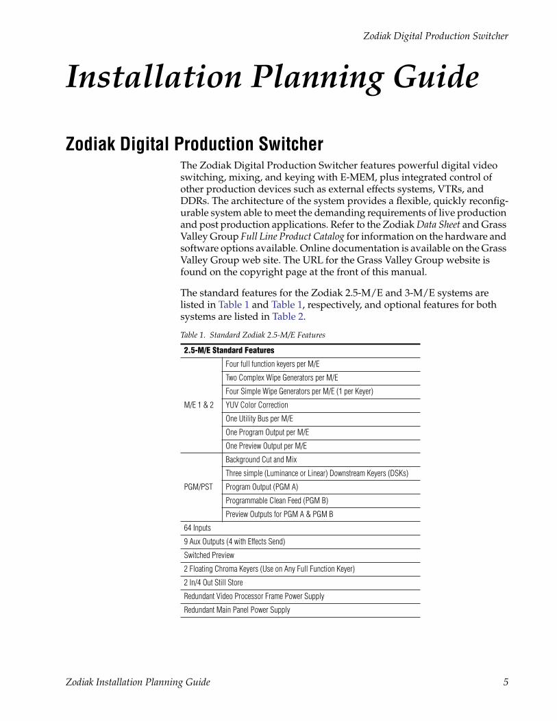
Zodiak Digital Production SwitcherThe Zodiak Digital Production Switcher features powerful digital video switching, mixing, and keying with E-MEM, plus integrated control of other production devices such as external effects systems, VTRs, and DDRs. The architecture of the system provides a flexible, quickly reconfig-urable system able to meet the demanding requirements of live production and post production applications. Refer to the Zodiak Data Sheet and Grass Valley Group Full Line Product Catalog for information on the hardware and software options available. Online documentation is available on the Grass Valley Group web site. The URL for the Grass Valley Group website is found on the copyright page at the front of this manual.
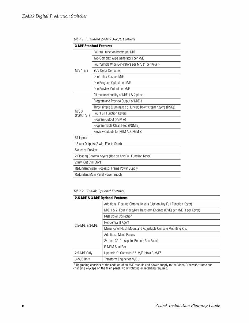
The standard features for the Zodiak 2.5-M/E and 3-M/E systems are listed in Table 1 and Table 1, respectively, and optional features for both systems are listed in Table 2.
Table 1. Standard Zodiak 2.5-M/E Features
2.5-M/E Standard Features
M/E 1 & 2
Four full function keyers per M/E
Two Complex Wipe Generators per M/E
Four Simple Wipe Generators per M/E (1 per Keyer)
YUV Color Correction
One Utility Bus per M/E
One Program Output per M/E
One Preview Output per M/E
PGM/PST
Background Cut and Mix
Three simple (Luminance or Linear) Downstream Keyers (DSKs)
Program Output (PGM A)
Programmable Clean Feed (PGM B)
Preview Outputs for PGM A & PGM B
64 Inputs
9 Aux Outputs (4 with Effects Send)
Switched Preview
2 Floating Chroma Keyers (Use on Any Full Function Keyer)
2 In/4 Out Still Store
Redundant Video Processor Frame Power Supply
Redundant Main Panel Power Supply
Zodiak Installation Planning Guide 5
Zodiak Digital Production Switcher
Table 1. Standard Zodiak 3-M/E Features
3-M/E Standard Features
M/E 1 & 2
Four full function keyers per M/E
Two Complex Wipe Generators per M/E
Four Simple Wipe Generators per M/E (1 per Keyer)
YUV Color Correction
One Utility Bus per M/E
One Program Output per M/E
One Preview Output per M/E
M/E 3(PGM/PST)
All the functionality of M/E 1 & 2 plus:
Program and Preview Output of M/E 3
Three simple (Luminance or Linear) Downstream Keyers (DSKs)
Four Full Function Keyers
Program Output (PGM A)
Programmable Clean Feed (PGM B)
Preview Outputs for PGM A & PGM B
64 Inputs
13 Aux Outputs (8 with Effects Send)
Switched Preview
2 Floating Chroma Keyers (Use on Any Full Function Keyer)
2 In/4 Out Still Store
Redundant Video Processor Frame Power Supply
Redundant Main Panel Power Supply
Table 2. Zodiak Optional Features
2.5-M/E & 3-M/E Optional Features
2.5-M/E & 3-M/E
Additional Floating Chroma Keyers (Use on Any Full Function Keyer)
M/E 1 & 2: Four Video/Key Transform Engines (DVE) per M/E (1 per Keyer)
RGB Color Correction
Net Central II Agent
Menu Panel Flush Mount and Adjustable Console Mounting Kits
Additional Menu Panels
24- and 32-Crosspoint Remote Aux Panels
E-MEM Shot Box
2.5-M/E Only Upgrade Kit Converts 2.5-M/E into a 3-M/Ea
a Upgrading consists of the addition of an M/E module and power supply to the Video Processor frame andchanging keycaps on the Main panel. No retrofitting or recabling required.
3-M/E Only Transform Engine for M/E 3
6 Zodiak Installation Planning Guide
Standard System Components
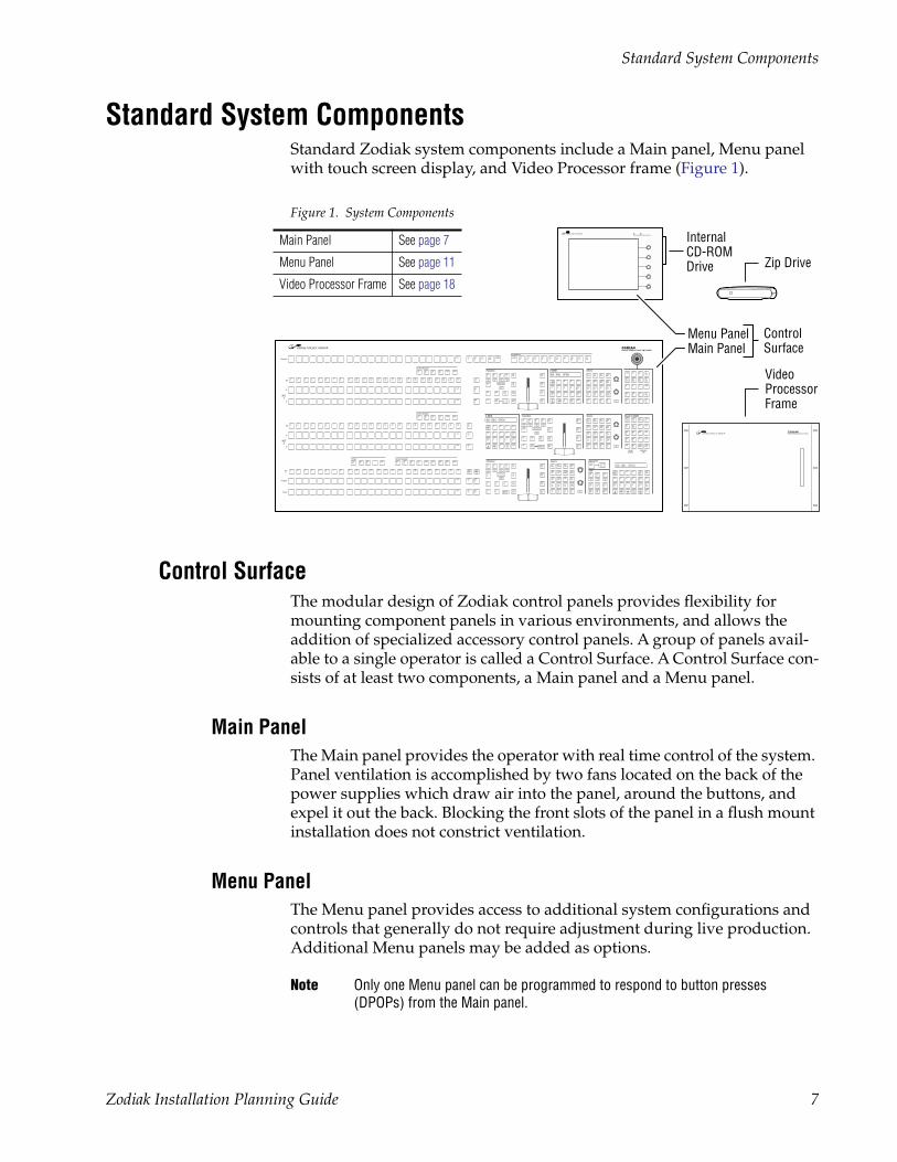
Standard System ComponentsStandard Zodiak system components include a Main panel, Menu panel with touch screen display, and Video Processor frame (Figure 1).
Figure 1. System Components
Control SurfaceThe modular design of Zodiak control panels provides flexibility for mounting component panels in various environments, and allows the addition of specialized accessory control panels. A group of panels avail-able to a single operator is called a Control Surface. A Control Surface con-sists of at least two components, a Main panel and a Menu panel.
Main PanelThe Main panel provides the operator with real time control of the system. Panel ventilation is accomplished by two fans located on the back of the power supplies which draw air into the panel, around the buttons, and expel it out the back. Blocking the front slots of the panel in a flush mount installation does not constrict ventilation.
Menu PanelThe Menu panel provides access to additional system configurations and controls that generally do not require adjustment during live production. Additional Menu panels may be added as options.
Note Only one Menu panel can be programmed to respond to button presses (DPOPs) from the Main panel.
Key
A
B
M/E1
Key
A
B
M/E2
Key
Program
Pvw/Aux
Preset
DSK
Key Bus Delegate
Bus Delegate
Key Bus Delegate
Preview Key Bus Delegate
E-MEM Transition Keyers Master E-MEM
E-MEMTransition Keyers
Transition Keyers Fade to Black
RecallEnables
KeyframeEdit
On On On
Effects Send
Uncal
On
027
Key1
Key2
Key3
Key4
KeyPrior
Key1
DSKLink
Key1
Key1
Key1
TransPVW
Key1
Key1
PresetBlack
1 2 3 4 5 6 7 8 9 10 11 12 13 14 15 16 17 18 19 20 21 22 23 Shift
Shift
Shift
B0 001 OPEN
1 2 3 4 5 6 7 8 9 10 11 12 13 14 15 16 17 18 19 20 21 22 23 Shift
Shift
Shift
Key1
Key2
Key3
Key4
Utility Macro
1 2 3 4 5 6 7 8 9 10 11 12 13 14 15 16 17 18 19 20 21 22 23 Shift
Shift
Shift
Key1
Key2
Key3
Key4
Utility Macro
Key 1Mix
Key 4Mix
Key 3Mix
Key 2Mix
TransRate
0 Enter
EffectDis
1 2 3 Bank1
Seq 4 5 6 Bank0
7 8 9 RunLockLearn
Bank
Undo•
Key1
LinKey
Video Key
MatteFill
IntDPM
Key2
LumKey
FreezeKey
FreezeFill
ExtDPM
Key3
ChrKey
Split
InhibitMask
KeyInvert
Key4
PresetPattrn
KeyOver
ForceMask
ShowKey
B0 001 OPEN
B0 001 OPEN
M/E2
M/E2
M/E 2Delay
032
On On On
Effects Send
Uncal
On
Key1
Key2
Key3
Key4
KeyPrior
Bkgd DSKLink
Mix Wipe UserTrans
TransPVW
Cut AutoTrans
PresetBlack
TransRate
0 Enter
EffectDis
1 2 3 Bank1
Seq 4 5 6 Bank0
7 8 9 RunLockLearn
Bank
Undo•
Key 1Mix
Key 4Mix
Key 3Mix
Key 2Mix
Key1
LinKey
Video Key
MatteFill
IntDPM
Key2
LumKey
FreezeKey
FreezeFill
ExtDPM
Key3
ChrKey
Split
InhibitMask
KeyInvert
Key4
PresetPattrn
KeyOver
ForceMask
ShowKey
Key 1Mix
Key 4Mix
Key 3Mix
Key 2Mix
Key1
LinKey
Video Key
MatteFill
IntDPM
Key2
LumKey
FreezeKey
FreezeFill
ExtDPM
Key3
ChrKey
Split
InhibitMask
KeyInvert
Key4
PresetPatter
KeyOver
ForceMask
ShowKey
Key1
M/E1
X
KeySource
Locate
Key2
M/E2
Y
KeyWipe
Size
Key3
M/E3
Z
BoxMask
Spin
Key4
ExtDPM
Center
PriWipe
SrcSpace
DSK1
DSK2
DSK3
DSK 1Cut
DSK 2Cut
DSK 3Cut
DSK 1Mix
DSK 2Mix
DSK 3Mix
TransRate
+/-0
TrimEnter
EffectDis
1 2 3 Bank1
Seq 4 5 6 Bank0
7 8 9 StopNextKF
Run
Re-wind
Rev
HoldInput
LockLearn
Bank
Undo•
AutoRecall
AutoRun
ClearWk Bfr
Go ToKF
M/E1
ExtDPM
Prev Next
M/E2
Misc1
Mod Paste
M/E3
Misc2
Cut Copy
DSK Misc3
InsertBefore
InsertAfter
PVW Aux1
Aux2
Aux3
Aux4
Aux5
Aux6
Aux7
Aux8
Aux9
Aux10
CleanFeed
PGMShift M/E1
M/E2
M/E2
M/E2
M/E2
On On On
Effects Send
Uncal
On
015
Key1
Key2
Key3
Key4
KeyPrior
Bkgd DSKLink
Mix Wipe UserTrans
TransPVW
Cut AutoTrans
PresetBlack On
On
On
On On On
M/E1
M/E1
M/E1
M/E1
M/E1
M/E 1Rec
M/E2
M/E1
PvwPri
DSK MacroKey4
Key3
Key2
Key1
Utility DSK1
DSK2
DSK3
M/E3
M/E3
027Fade toBlack
InternalCD-ROM Drive Zip Drive
ControlSurface
Menu PanelMain Panel
Video ProcessorFrame
Main Panel See page 7
Menu Panel See page 11
Video Processor Frame See page 18
Zodiak Installation Planning Guide 7
Installation
Removable Media DrivesFour removable media drives are standard components of a Zodiak system:
• A CD-ROM in the Menu panel (see Figure 8),
• An external 250 MB Zip drive connected through and powered by the USB port on the Menu panel (see Figure 9), and
• Two standard 1.4 MB 3.5 in. floppy disk drives, one in the Main Panel tub (see Figure 2) and one in the Video Processor frame (see Figure 18).
Note The floppy disk drives are used exclusively for emergency boot procedures.
Installation
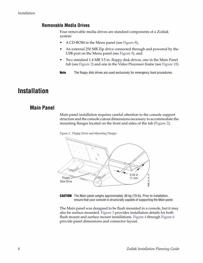
Main PanelMain panel installation requires careful attention to the console support structure and the console cutout dimensions necessary to accommodate the mounting flanges located on the front and sides of the tub (Figure 2).
Figure 2. Floppy Drive and Mounting Flanges
CAUTION The Main panel weighs approximately 36 kg (79 lb). Prior to installation, ensure that your console is structurally capable of supporting the Main panel.
The Main panel was designed to be flush mounted in a console, but it may also be surface mounted. Figure 3 provides installation details for both flush mount and surface mount installations. Figure 4 through Figure 6 provide panel dimensions and connector layout.
8096
_01_
01_r
0
FloppyDisk Drive
0.43 in.11 mm
8 Zodiak Installation Planning Guide
Installation
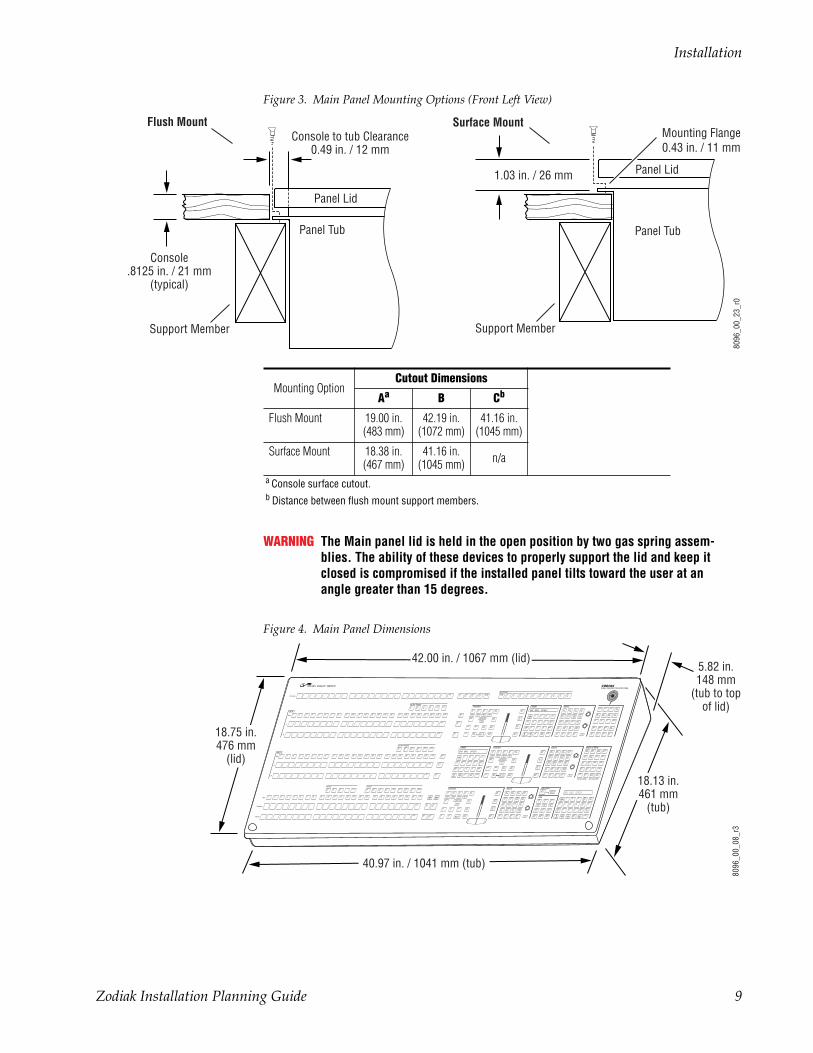
Figure 3. Main Panel Mounting Options (Front Left View)
WARNING The Main panel lid is held in the open position by two gas spring assem-blies. The ability of these devices to properly support the lid and keep it closed is compromised if the installed panel tilts toward the user at an angle greater than 15 degrees.
Figure 4. Main Panel Dimensions
Flush MountConsole to tub Clearance
0.49 in. / 12 mm
Console.8125 in. / 21 mm
(typical)
Panel Tub
Panel Lid
Support Member
8096
_00_
23_r
0
Mounting Flange0.43 in. / 11 mm
Panel Tub
Panel Lid
Support Member
Surface Mount
1.03 in. / 26 mm
Mounting OptionCutout Dimensions
Aa
a Console surface cutout.
B Cb
b Distance between flush mount support members.
Flush Mount 19.00 in. (483 mm)
42.19 in. (1072 mm)
41.16 in. (1045 mm)
Surface Mount 18.38 in. (467 mm)
41.16 in. (1045 mm) n/a
Key
A
B
M/E 1
Key
A
B
M/E 2
Key
Program
Pvw/Aux
Preset
DSK
Key Bus Delegate
Bus Delegate
Key Bus Delegate
Preview Preview
E-MEM Transition Keyers Master E-MEM
E-MEMTransition Keyers
Transition Keyers Fade to Black
Recall Enables Key Frame Edit
On On On
Effects Send
Uncal
On
027
Key1
Key2
Key3
Key4
KeyPrior
Key1
DSKLink
Key1
Key1
Key1
TransPVW
Key1
Key1
PresetBlack
1 2 3 4 5 6 7 8 9 10 11 12 13 14 15 16 17 18 19 20 21 22 23 Shift
Shift
Shift
B0 001 OPEN
1 2 3 4 5 6 7 8 9 10 11 12 13 14 15 16 17 18 19 20 21 22 23 Shift
Shift
Shift
Key1
Key2
Key3
Key4
Utility Macro
1 2 3 4 5 6 7 8 9 10 11 12 13 14 15 16 17 18 19 20 21 22 23 Shift
Shift
Shift
Key1
Key2
Key3
Key4
Utility Macro
Key 1Mix
Key 4Mix
Key 3Mix
Key 2Mix
TransRate
0 Enter
EffectDis
1 2 3 Bank1
Seq 4 5 6 Bank0
7 8 9 RunLockLearn
BankUndo•
Key1
LinKey
Video Key
MatteFill
IntDPM
Key2
LumKey
FreezeKey
FreezeFill
ExtDPM
Key3
ChrKey
Split
InhibitMask
KeyInvert
Key4
PresetPattrn
KeyOver
ForceMask
ShowKey
B0 001 OPEN
B0 001 OPEN
M/E2
M/E2
M/E 2Delay
032
On On On
Effects Send
Uncal
On
Key1
Key2
Key3
Key4
KeyPrior
Bkgd DSKLink
Mix Wipe UserTrans
TransPVW
Cut AutoTrans
PresetBlack
TransRate
0 Enter
EffectDis
1 2 3 Bank1
Seq 4 5 6 Bank0
7 8 9 RunLockLearn
BankUndo•
Key 1Mix
Key 4Mix
Key 3Mix
Key 2Mix
Key1
LinKey
Video Key
MatteFill
IntDPM
Key2
LumKey
FreezeKey
FreezeFill
ExtDPM
Key3
ChrKey
Split
InhibitMask
KeyInvert
Key4
PresetPattrn
KeyOver
ForceMask
ShowKey
Key 1Mix
Key 4Mix
Key 3Mix
Key 2Mix
Key1
LinKey
Video Key
MatteFill
IntDPM
Key2
LumKey
FreezeKey
FreezeFill
ExtDPM
Key3
ChrKey
Split
InhibitMask
KeyInvert
Key4
PresetPatter
KeyOver
ForceMask
ShowKey
Key1
M/E1
X
KeySource
Locate
Key2
M/E2
Y
KeyWipe
Size
Key3
M/E3
Z
BoxMask
Spin
Key4
ExtDPM
Center
PriWipe
SrcSpace
DSK1
DSK2
DSK3
DSK 1Cut
DSK 2Cut
DSK 3Cut
DSK 1Mix
DSK 2Mix
DSK 3Mix
TransRate
+/-
0Trim
Enter
EffectDis
1 2 3 Bank1
Seq 4 5 6 Bank0
7 8 9 StopNext
KF
Run
Re-wind
Rev
HoldInput
LockLearn
BankUndo•
AutoRecall
AutoRun
ClearWk Bfr
Go ToKF
M/E1
ExtDPM
Prev Next
M/E2
Misc1
Mod Paste
M/E3
Misc2
Cut Copy
DSK Misc3
InsertBefore
InsertAfter
PVW Aux1
Aux2
Aux3
Aux4
Aux5
Aux6
Aux7
Aux8
Aux9
Aux10
CleanFeed
PGMShift M/E1
M/E2
M/E2
M/E2
M/E2 On On On
Effects Send
Uncal
On
015
Key1
Key2
Key3
Key4
KeyPrior
Bkgd DSKLink
Mix Wipe UserTrans
TransPVW
Cut AutoTrans
PresetBlack On
On
On
On On On
M/E1
M/E1
M/E1
M/E1
M/E1
M/E 1Rec
M/E2
M/E1
PvwPri
DSK MacroKey4
Key3
Key2
Key1
Utility DSK1
DSK2
DSK3
M/E3
M/E3
ZODIAKVIDEO PRODUCT ION SWITCHER
027Fade to
Black
18.75 in.476 mm
(lid)
42.00 in. / 1067 mm (lid)
40.97 in. / 1041 mm (tub)
18.13 in.461 mm
(tub)
5.82 in.148 mm
(tub to topof lid)
8096
_00_
08_r
3
Zodiak Installation Planning Guide 9
Installation
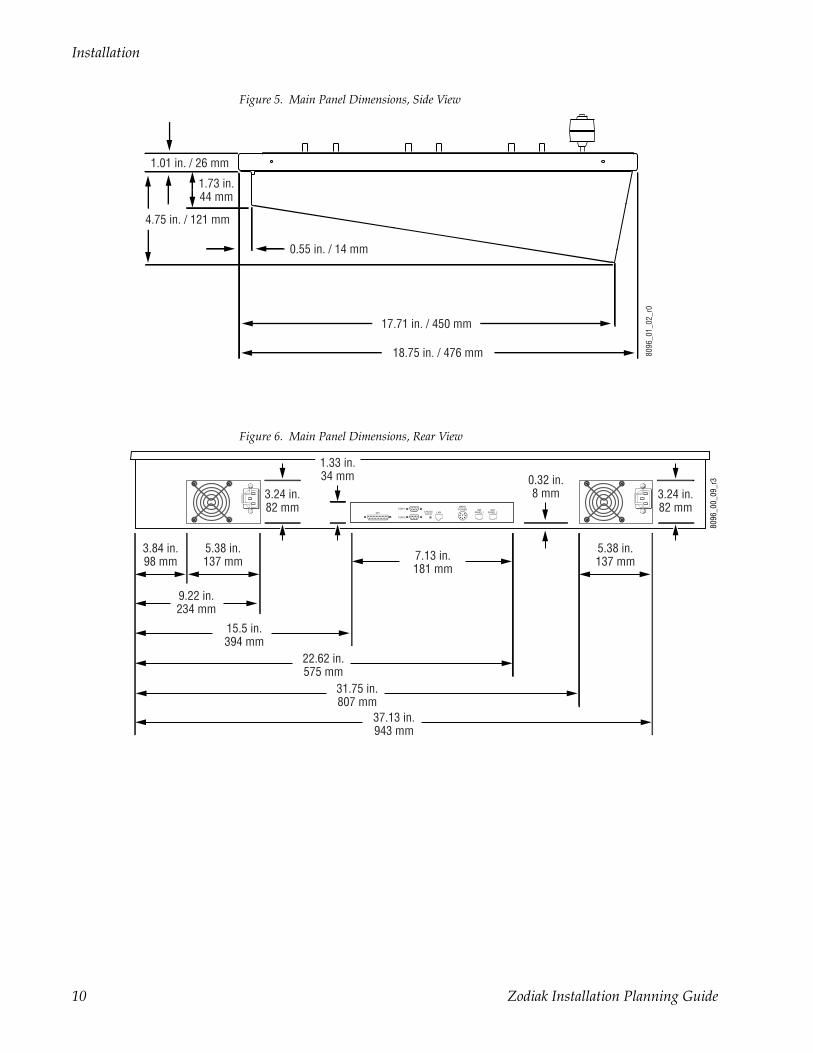
Figure 5. Main Panel Dimensions, Side View
Figure 6. Main Panel Dimensions, Rear View
8096
_01_
02_r
0
1.73 in.44 mm
18.75 in. / 476 mm
17.71 in. / 450 mm
0.55 in. / 14 mm
1.01 in. / 26 mm
4.75 in. / 121 mm
GPI LAN
COM 1CROSSOVER
MENUPOWER SAT
PANEL 1SAT
PANEL 2
COM 2
8096
_00_
09_r
3
9.22 in.234 mm
5.38 in.137 mm
5.38 in.137 mm7.13 in.
181 mm
0.32 in.8 mm3.24 in.
82 mm
3.84 in.98 mm
15.5 in.394 mm
22.62 in.575 mm
31.75 in.807 mm
37.13 in.943 mm
3.24 in.82 mm
1.33 in.34 mm
10 Zodiak Installation Planning Guide
Installation
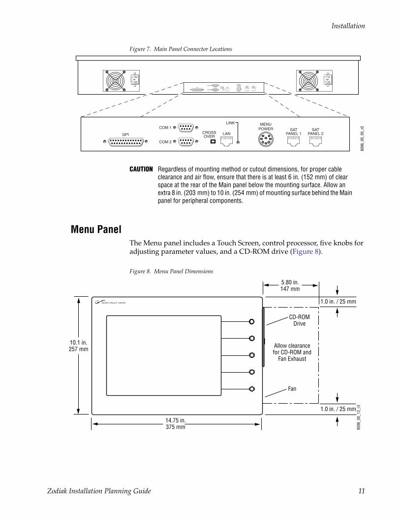
Figure 7. Main Panel Connector Locations
CAUTION Regardless of mounting method or cutout dimensions, for proper cable clearance and air flow, ensure that there is at least 6 in. (152 mm) of clear space at the rear of the Main panel below the mounting surface. Allow an extra 8 in. (203 mm) to 10 in. (254 mm) of mounting surface behind the Main panel for peripheral components.
Menu PanelThe Menu panel includes a Touch Screen, control processor, five knobs for adjusting parameter values, and a CD-ROM drive (Figure 8).
Figure 8. Menu Panel Dimensions
8096
_00_
05_r
0
GPI LAN
COM 1CROSSOVER
MENUPOWER SAT
PANEL 1SAT
PANEL 2
COM 2
GPI LAN
LINKCOM 1
CROSSOVER
MENUPOWER SAT
PANEL 1SAT
PANEL 2
COM 2
8096
_00_
13_r
3
14.75 in.375 mm
10.1 in.257 mm
5.80 in.147 mm
Allow clearancefor CD-ROM and
Fan Exhaust
1.0 in. / 25 mm
Fan
1.0 in. / 25 mm
CD-ROMDrive
Zodiak Installation Planning Guide 11
Installation
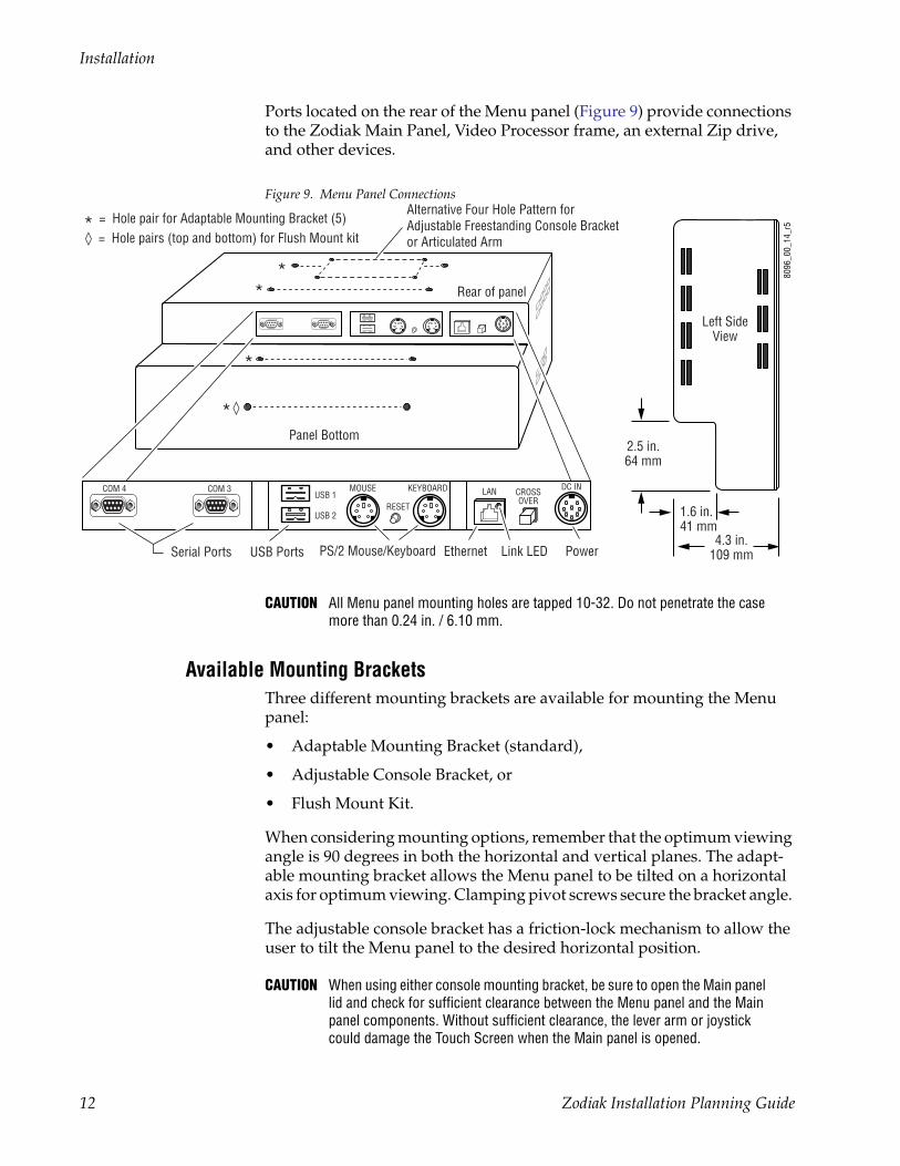
Ports located on the rear of the Menu panel (Figure 9) provide connections to the Zodiak Main Panel, Video Processor frame, an external Zip drive, and other devices.
Figure 9. Menu Panel Connections
CAUTION All Menu panel mounting holes are tapped 10-32. Do not penetrate the case more than 0.24 in. / 6.10 mm.
Available Mounting BracketsThree different mounting brackets are available for mounting the Menu panel:
• Adaptable Mounting Bracket (standard),
• Adjustable Console Bracket, or
• Flush Mount Kit.
When considering mounting options, remember that the optimum viewing angle is 90 degrees in both the horizontal and vertical planes. The adapt-able mounting bracket allows the Menu panel to be tilted on a horizontal axis for optimum viewing. Clamping pivot screws secure the bracket angle.
The adjustable console bracket has a friction-lock mechanism to allow the user to tilt the Menu panel to the desired horizontal position.
CAUTION When using either console mounting bracket, be sure to open the Main panel lid and check for sufficient clearance between the Menu panel and the Main panel components. Without sufficient clearance, the lever arm or joystick could damage the Touch Screen when the Main panel is opened.
8096
_00_
14_r
5
2.5 in.64 mm
Left SideView
Panel Bottom
Rear of panel
Alternative Four Hole Pattern forAdjustable Freestanding Console Bracketor Articulated Arm
Serial Ports
1.6 in.41 mm
4.3 in.109 mm
**
*
*◊
= Hole pairs (top and bottom) for Flush Mount kit◊
= Hole pair for Adaptable Mounting Bracket (5)*
USB Ports PS/2 Mouse/Keyboard Ethernet Power
LAN DC INMOUSE KEYBOARDUSB 1
USB 2RESET
COM 3 CROSSOVER
COM 4
Link LED
12 Zodiak Installation Planning Guide
Installation
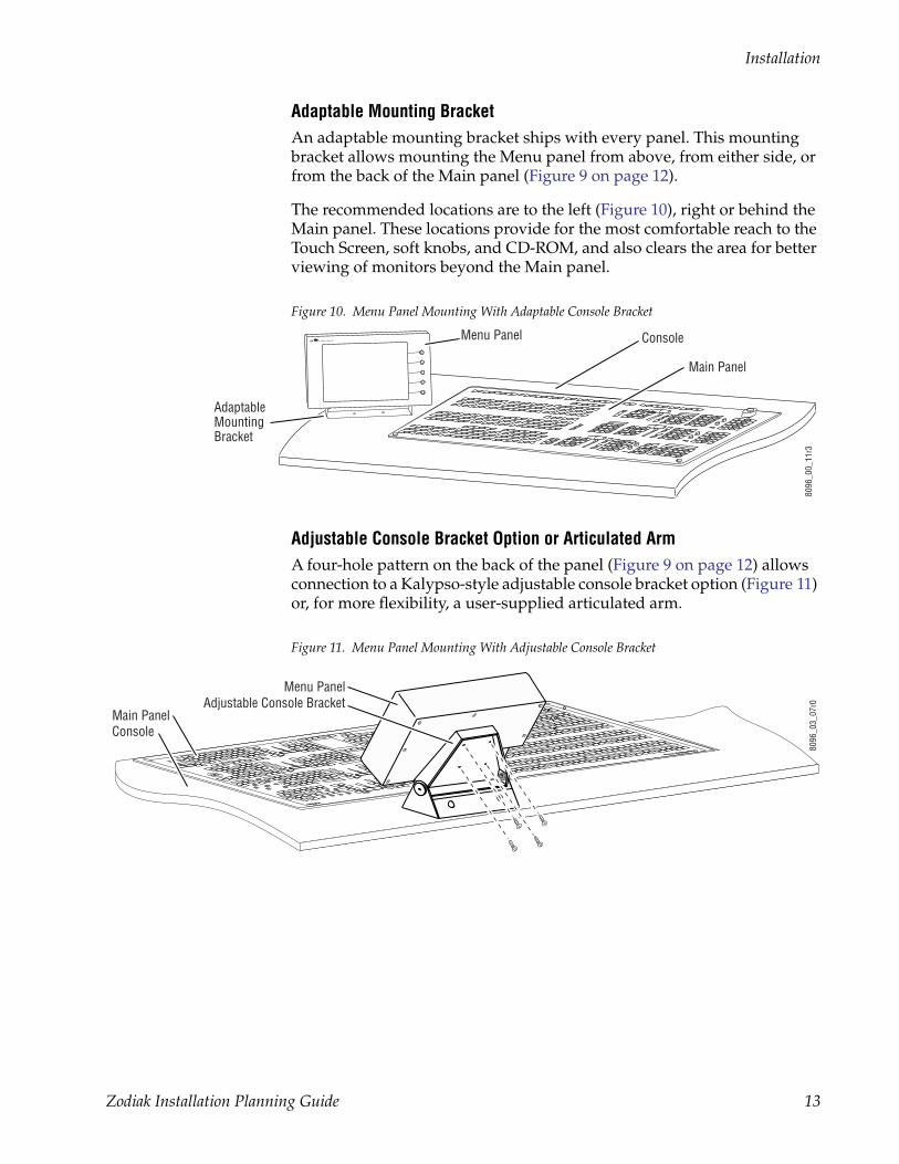
Adaptable Mounting BracketAn adaptable mounting bracket ships with every panel. This mounting bracket allows mounting the Menu panel from above, from either side, or from the back of the Main panel (Figure 9 on page 12).
The recommended locations are to the left (Figure 10), right or behind the Main panel. These locations provide for the most comfortable reach to the Touch Screen, soft knobs, and CD-ROM, and also clears the area for better viewing of monitors beyond the Main panel.
Figure 10. Menu Panel Mounting With Adaptable Console Bracket
Adjustable Console Bracket Option or Articulated ArmA four-hole pattern on the back of the panel (Figure 9 on page 12) allows connection to a Kalypso-style adjustable console bracket option (Figure 11) or, for more flexibility, a user-supplied articulated arm.
Figure 11. Menu Panel Mounting With Adjustable Console Bracket
8096
_00_
11r3
Menu Panel
Adaptable Mounting Bracket
Console
Main Panel
Grass V Grass Valley alley Group
Kalypso Kalypso
8096
_03_
07r0
Menu PanelAdjustable Console Bracket
ConsoleMain Panel
Zodiak Installation Planning Guide 13
Installation
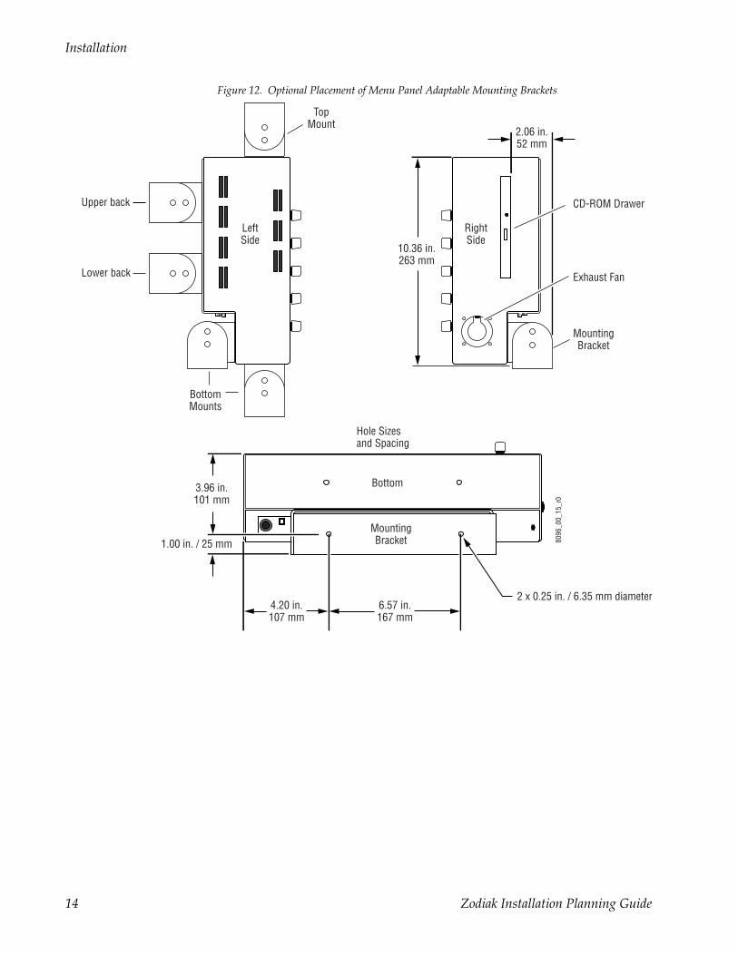
Figure 12. Optional Placement of Menu Panel Adaptable Mounting Brackets
2.06 in.52 mm
10.36 in.263 mm
BottomMounts
6.57 in.167 mm
2 x 0.25 in. / 6.35 mm diameter
Bottom
LeftSide
RightSide
MountingBracket
4.20 in.107 mm
3.96 in.101 mm
1.00 in. / 25 mm
Upper back
Lower back
CD-ROM Drawer
TopMount
MountingBracket
Hole Sizesand Spacing
8096
_00_
15_r
0
Exhaust Fan
14 Zodiak Installation Planning Guide
Installation
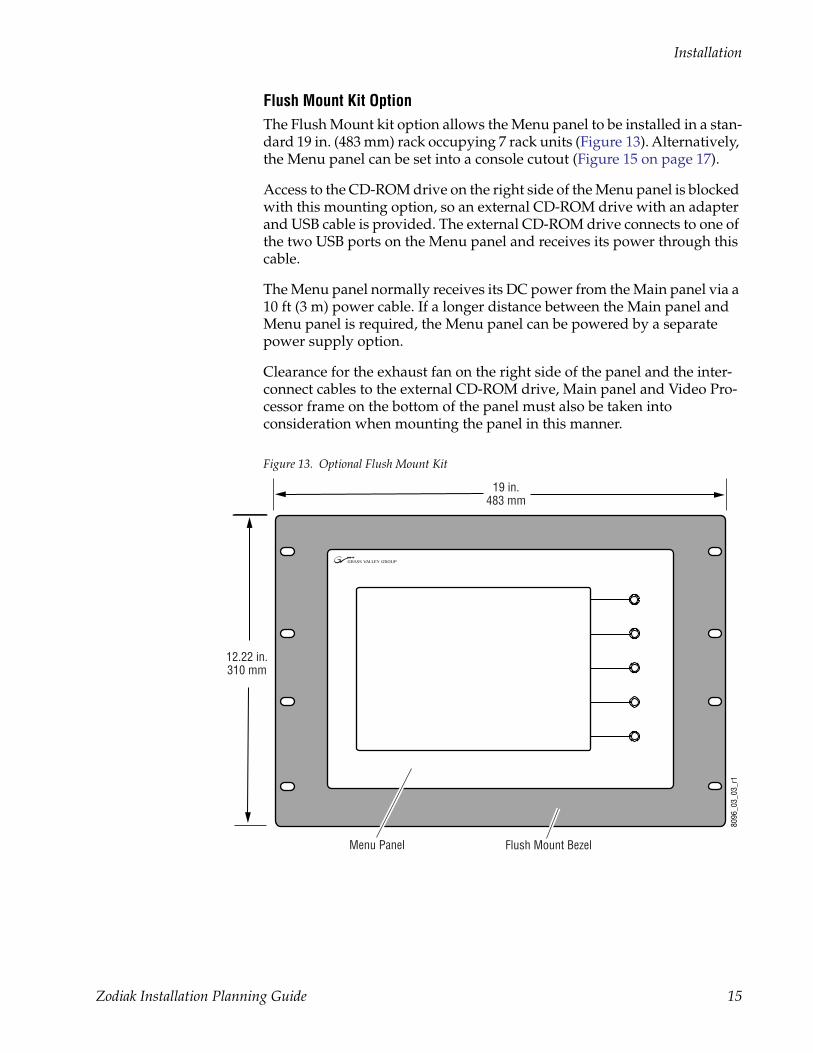
Flush Mount Kit OptionThe Flush Mount kit option allows the Menu panel to be installed in a stan-dard 19 in. (483 mm) rack occupying 7 rack units (Figure 13). Alternatively, the Menu panel can be set into a console cutout (Figure 15 on page 17).
Access to the CD-ROM drive on the right side of the Menu panel is blocked with this mounting option, so an external CD-ROM drive with an adapter and USB cable is provided. The external CD-ROM drive connects to one of the two USB ports on the Menu panel and receives its power through this cable.
The Menu panel normally receives its DC power from the Main panel via a 10 ft (3 m) power cable. If a longer distance between the Main panel and Menu panel is required, the Menu panel can be powered by a separate power supply option.
Clearance for the exhaust fan on the right side of the panel and the inter-connect cables to the external CD-ROM drive, Main panel and Video Pro-cessor frame on the bottom of the panel must also be taken into consideration when mounting the panel in this manner.
Figure 13. Optional Flush Mount Kit
8096
_03_
03_r
1
Flush Mount BezelMenu Panel
19 in.483 mm
12.22 in.310 mm
Zodiak Installation Planning Guide 15
Installation
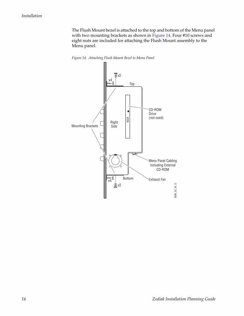
The Flush Mount bezel is attached to the top and bottom of the Menu panel with two mounting brackets as shown in Figure 14. Four #10 screws and eight nuts are included for attaching the Flush Mount assembly to the Menu panel.
Figure 14. Attaching Flush Mount Bezel to Menu Panel
Mounting Brackets
x2
x2x4
Top
Bottom
RightSide
Exhaust Fan
CD-ROMDrive(not used)
8096
_03_
04_r
2
Menu Panel CablingIncluding External
CD-ROM
x4
16 Zodiak Installation Planning Guide
Installation
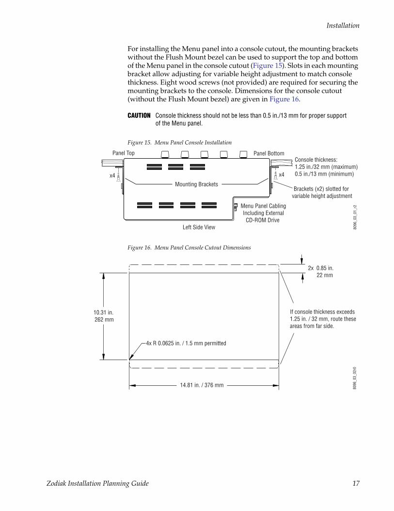
For installing the Menu panel into a console cutout, the mounting brackets without the Flush Mount bezel can be used to support the top and bottom of the Menu panel in the console cutout (Figure 15). Slots in each mounting bracket allow adjusting for variable height adjustment to match console thickness. Eight wood screws (not provided) are required for securing the mounting brackets to the console. Dimensions for the console cutout (without the Flush Mount bezel) are given in Figure 16.
CAUTION Console thickness should not be less than 0.5 in./13 mm for proper support of the Menu panel.
Figure 15. Menu Panel Console Installation
Figure 16. Menu Panel Console Cutout Dimensions
Left Side View
Brackets (x2) slotted for variable height adjustment
Menu Panel CablingIncluding External
CD-ROM Drive
Panel Top Panel Bottom
8096
_03_
01_r
2
Mounting Brackets
x4x4
Console thickness:1.25 in./32 mm (maximum)0.5 in./13 mm (minimum)
10.31 in. 262 mm
If console thickness exceeds 1.25 in. / 32 mm, route these areas from far side.
14.81 in. / 376 mm
4x R 0.0625 in. / 1.5 mm permitted
2x 0.85 in. 22 mm
8096
_03_
02r0
Zodiak Installation Planning Guide 17
Installation
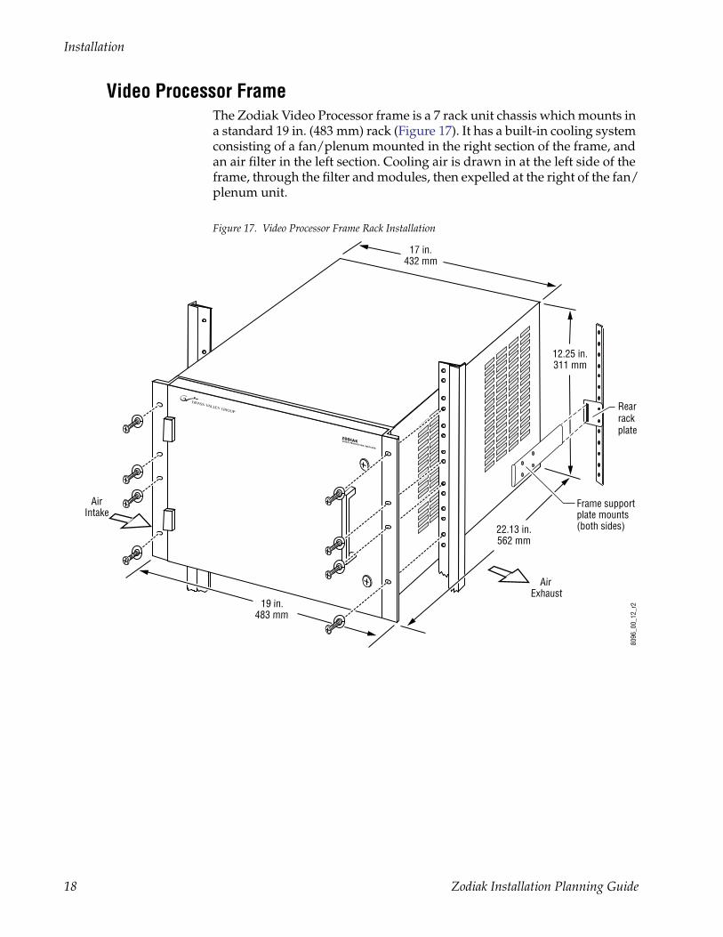
Video Processor FrameThe Zodiak Video Processor frame is a 7 rack unit chassis which mounts in a standard 19 in. (483 mm) rack (Figure 17). It has a built-in cooling system consisting of a fan/plenum mounted in the right section of the frame, and an air filter in the left section. Cooling air is drawn in at the left side of the frame, through the filter and modules, then expelled at the right of the fan/plenum unit.
Figure 17. Video Processor Frame Rack Installation
17 in.432 mm
12.25 in.311 mm
22.13 in.562 mm
AirIntake
19 in.483 mm
8096
_00_
12_r
2
Air Exhaust
Frame supportplate mounts(both sides)
Rear rack plate
18 Zodiak Installation Planning Guide
Installation
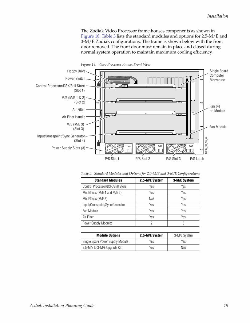
The Zodiak Video Processor frame houses components as shown in Figure 18. Table 3 lists the standard modules and options for 2.5-M/E and 3-M/E Zodiak configurations. The frame is shown below with the front door removed. The front door must remain in place and closed during normal system operation to maintain maximum cooling efficiency.
Figure 18. Video Processor Frame, Front View
Table 3. Standard Modules and Options for 2.5-M/E and 3-M/E Configurations
Standard Modules 2.5-M/E System 3-M/E System
Control Processor/DSK/Still Store Yes Yes
Mix Effects (M/E 1 and M/E 2) Yes Yes
Mix Effects (M/E 3) N/A Yes
Input/Crosspoint/Sync Generator Yes Yes
Fan Module Yes Yes
Air Filter Yes Yes
Power Supply Modules 2 3
Module Options 2.5-M/E System 3-M/E System
Single Spare Power Supply Module Yes Yes
2.5-M/E to 3-M/E Upgrade Kit Yes N/A
8096
_00_
16_r
2
ON
OFFControl Processor/DSK/Still Store(Slot 1)
M/E (M/E 1 & 2)(Slot 2)
Fan Module
Floppy Drive
M/E (M/E 3)(Slot 3)
Input/Crosspoint/Sync Generator(Slot 4)
Power Supply Slots (3)
Air Filter
Air Filter Handle
Fan (4)on Module
P/S Slot 2P/S Slot 1 P/S Slot 3 P/S Latch
Single BoardComputerMezzaninePower Switch
Zodiak Installation Planning Guide 19
Installation
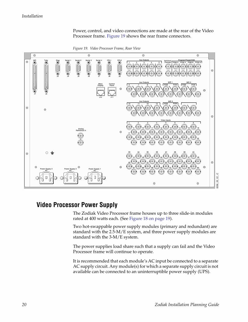
Power, control, and video connections are made at the rear of the Video Processor frame. Figure 19 shows the rear frame connectors.
Figure 19. Video Processor Frame, Rear View
Video Processor Power SupplyThe Zodiak Video Processor frame houses up to three slide-in modules rated at 400 watts each. (See Figure 18 on page 19).
Two hot-swappable power supply modules (primary and redundant) are standard with the 2.5-M/E system, and three power supply modules are standard with the 3-M/E system.
The power supplies load share such that a supply can fail and the Video Processor frame will continue to operate.
It is recommended that each module’s AC input be connected to a separate AC supply circuit. Any module(s) for which a separate supply circuit is not available can be connected to an uninterruptible power supply (UPS).
Aux OutputsAux Outputs
Aux OutputsAux Outputs
PGMPGM PVWPVW
M/E 2M/E 2M/E 1M/E 1
Power Supply 1Power Supply 1ACAC
Power Supply 2Power Supply 2ACAC
Power Supply 3Power Supply 3ACAC
AnalogAnalogReference InReference In
646463626261616060595958585757
56565555545453535252515150504949
48484747464645454444434342424141
403939383837373636353534343333
32323131303029292828272726262525
242423222221212020191918181717
1616151413131212111110109
87654321
Video InputsVideo Inputs
M/E 3M/E 3
PVWPVWPGMPGMPVWPVWPGMPGM
1313121211111010
9876
PrograProgram/m/PresePreset/DSKDSKAux OutputsAux Outputs
ControlControlPanelPanel
MenuMenuDisplayDisplay
J11J11J10J10
J9J9J8J8J7J7J6J6J5J5J4J4J3J3
J2J2J1J1
PVW BPVW BPGM BPGM BPVW APVW APGM APGM ASwitchedSwitchedPreviewPreview54321
CPL2CPL2CPL1CPL1Serial 4Serial 4Serial 3Serial 3Serial 2Serial 2Serial 1Serial 1DiagDiagTallyTallyGPIGPI
8096
_00_
02_r
2
20 Zodiak Installation Planning Guide
Optional Components
Optional Components
Remote Aux PanelsRemote Aux panels control Zodiak aux buses from remote locations. Three 24-Crosspoint and two 32-Crosspoint Remote Aux panel configurations are available for Zodiak systems. Refer to Table 4 and the following sections for panel-specific information.
Remote aux panels may be purchased with the Zodiak system or added at a later time. For more information on Zodiak options, refer to the Zodiak Data Sheet or Grass Valley Group Full Line Product Catalog. Online docu-mentation is available at www.grassvalleygroup.com.
Note Remote Aux panels used with Model 2200, 3000, and 4000 systems can be upgraded for use in a Zodiak environment. See the Kalypso Model 4000 Remote Aux Panel Upgrade Instruction Manual for details.
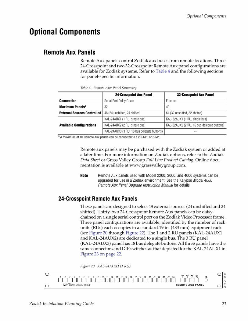
24-Crosspoint Remote Aux PanelsThese panels are designed to select 48 external sources (24 unshifted and 24 shifted). Thirty-two 24-Crosspoint Remote Aux panels can be daisy-chained on a single serial control port on the Zodiak Video Processor frame. Three panel configurations are available, identified by the number of rack units (RUs) each occupies in a standard 19 in. (483 mm) equipment rack (see Figure 20 through Figure 22). The 1 and 2 RU panels (KAL-24AUX1 and KAL-24AUX2) are dedicated to a single bus. The 3 RU panel (KAL-24AUX3) panel has 18 bus delegate buttons. All three panels have the same connectors and DIP switches as that depicted for the KAL-24AUX1 in Figure 23 on page 22.
Figure 20. KAL-24AUX1 (1 RU)
Table 4. Remote Aux Panel Summary
24-Crosspoint Aux Panel 32-Crosspoint Aux Panel
Connection Serial Port Daisy Chain Ethernet
Maximum Panelsa
a A maximum of 40 Remote Aux panels can be connected to a 2.5-M/E or 3-M/E.
32 40
External Sources Controlled 48 (24 unshifted, 24 shifted) 64 (32 unshifted, 32 shifted)
Available Configurations
KAL-24AUX1 (1 RU, single bus) KAL-32AUX1 (1 RU, single bus)
KAL-24AUX2 (2 RU, single bus) KAL-32AUX2 (2 RU, 16 bus delegate buttons)
KAL-24AUX3 (3 RU, 18 bus delegate buttons) --
REMOTE AUX PANEL
11 2 3 4 5 6 7 8 9 1010 1111 1212 1313 1414 1515 1616 ONONAIRAIR1 2 3
PgmPgmPstPst
M/EM/E M/EM/E M/EM/E1717 1818 1919 2020 2121 2222 2323 2424 Shi f tShi f t
0619
_04_
64_r
1
Zodiak Installation Planning Guide 21
Optional Components
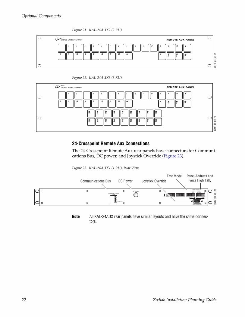
Figure 21. KAL-24AUX2 (2 RU)
Figure 22. KAL-24AUX3 (3 RU)
24-Crosspoint Remote Aux ConnectionsThe 24-Crosspoint Remote Aux rear panels have connectors for Communi-cations Bus, DC power, and Joystick Override (Figure 23).
Figure 23. KAL-24AUX1 (1 RU), Rear View
Note All KAL-24AUX rear panels have similar layouts and have the same connec-tors.
REMOTE AUX PANELREMOTE AUX PANEL
10109876542 31
242423232222
1111
21212020191918181717
1616151513131212 1414
PstPstPgmPgm
3M/EM/E
2M/EM/E
1M/EM/EShiftShift
0619
_04_
67_r
1
REMOTE AUX PANELREMOTE AUX PANEL
10109876542 31
242423232222
1111
21212020191918181717
1616151513131212 1414
PstPstPgmPgm
3M/EM/E
2M/EM/E
1M/EM/EShiftShift
3A3AAuxAux
2A2AAuxAux
1A1AAuxAux
9A9AAuxAuxAuxAux
8A8AAuxAux7A7A6A6A
AuxAux5A5AAuxAux
4A4AAuxAux
AuxAux4B4B
AuxAux5B5B3B3B
AuxAux2B2BAuxAux
1B1BAuxAux AuxAux
9B9B7B7BAuxAux
8B8BAuxAuxAuxAux
6B6B
0619
_04_
69_r
1
-
+
COMMUNICATIONSBUS
SHIELD
DC POWER
JOYSTICK OVERRIDE6432168421 8421
FORCE HIGH TALLY
MODETEST
ADDRESSPANEL
OFF
ON
0619
_04_
65_r
0
DC PowerTest Mode Panel Address and
Force High TallyJoystick OverrideCommunications Bus
22 Zodiak Installation Planning Guide
Optional Components
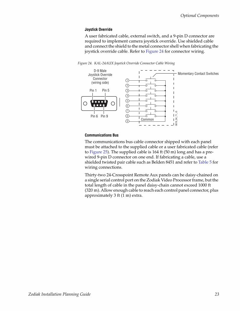
Joystick Override
A user fabricated cable, external switch, and a 9-pin D connector are required to implement camera joystick override. Use shielded cable and connect the shield to the metal connector shell when fabricating the joystick override cable. Refer to Figure 24 for connector wiring.
Figure 24. KAL-24AUX Joystick Override Connector Cable Wiring
Communications Bus
The communications bus cable connector shipped with each panel must be attached to the supplied cable or a user fabricated cable (refer to Figure 25). The supplied cable is 164 ft (50 m) long and has a pre-wired 9-pin D connector on one end. If fabricating a cable, use a shielded twisted pair cable such as Belden 8451 and refer to Table 5 for wiring connections.
Thirty-two 24-Crosspoint Remote Aux panels can be daisy-chained on a single serial control port on the Zodiak Video Processor frame, but the total length of cable in the panel daisy-chain cannot exceed 1000 ft (320 m). Allow enough cable to reach each control panel connector, plus approximately 3 ft (1 m) extra.
Momentary Contact Switches
0619
_04_
71_r
5
Pin 1
Pin 9Pin 6
Pin 5
Common
1
2
3
4
6
7
8
5
9
D-9 MaleJoystick Override
Connector(wiring side)
Zodiak Installation Planning Guide 23
Optional Components
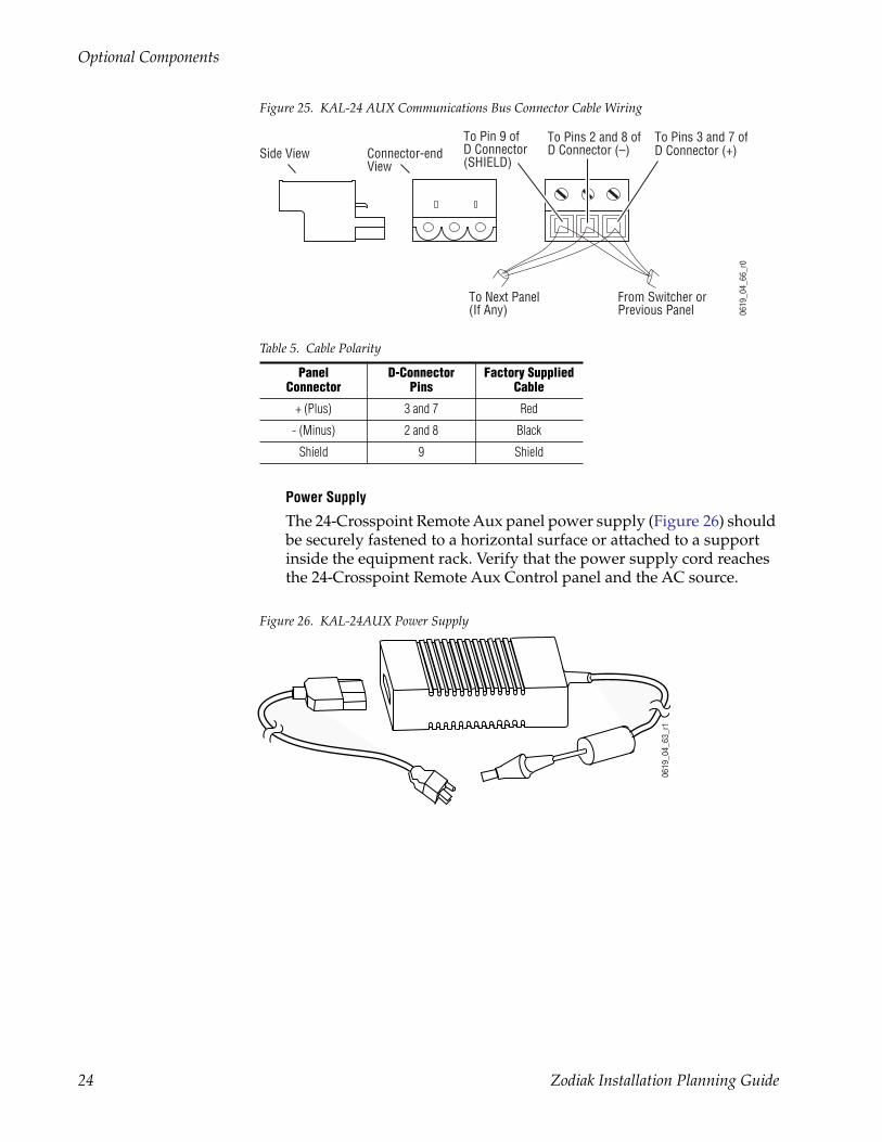
Figure 25. KAL-24 AUX Communications Bus Connector Cable Wiring
Power Supply
The 24-Crosspoint Remote Aux panel power supply (Figure 26) should be securely fastened to a horizontal surface or attached to a support inside the equipment rack. Verify that the power supply cord reaches the 24-Crosspoint Remote Aux Control panel and the AC source.
Figure 26. KAL-24AUX Power Supply
Table 5. Cable Polarity
Panel Connector
D-Connector Pins
Factory Supplied Cable
+ (Plus) 3 and 7 Red
- (Minus) 2 and 8 Black
Shield 9 Shield
0619
_04_
66_r
0
To Pin 9 ofD Connector(SHIELD)
To Pins 2 and 8 ofD Connector (–)
To Pins 3 and 7 ofD Connector (+)
To Next Panel(If Any)
Side View Connector-endView
From Switcher orPrevious Panel
0619
_04_
63_r
1
24 Zodiak Installation Planning Guide
Optional Components
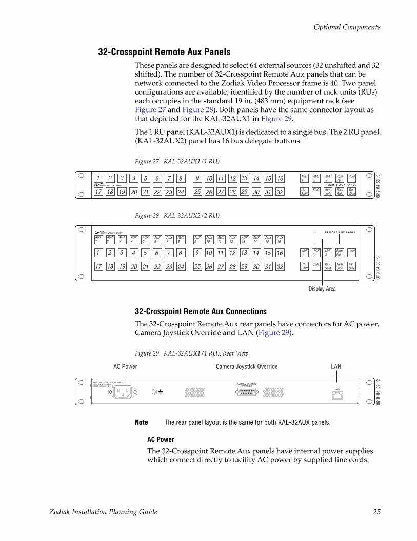
32-Crosspoint Remote Aux PanelsThese panels are designed to select 64 external sources (32 unshifted and 32 shifted). The number of 32-Crosspoint Remote Aux panels that can be network connected to the Zodiak Video Processor frame is 40. Two panel configurations are available, identified by the number of rack units (RUs) each occupies in the standard 19 in. (483 mm) equipment rack (see Figure 27 and Figure 28). Both panels have the same connector layout as that depicted for the KAL-32AUX1 in Figure 29.
The 1 RU panel (KAL-32AUX1) is dedicated to a single bus. The 2 RU panel (KAL-32AUX2) panel has 16 bus delegate buttons.
Figure 27. KAL-32AUX1 (1 RU)
Figure 28. KAL-32AUX2 (2 RU)
32-Crosspoint Remote Aux ConnectionsThe 32-Crosspoint Remote Aux rear panels have connectors for AC power, Camera Joystick Override and LAN (Figure 29).
Figure 29. KAL-32AUX1 (1 RU), Rear View
Note The rear panel layout is the same for both KAL-32AUX panels.
AC Power
The 32-Crosspoint Remote Aux panels have internal power supplies which connect directly to facility AC power by supplied line cords.
KALYPSO REMOTE AUX PANEL
1 2 3 4 5 6 7 8 9 10 11 12 13 14 15 16 M/E1
M/E2
M/E3
PgmPst
Hold
17 18 19 20 21 22 23 24 25 26 27 28 29 30 31 32 Un-Shift
Shift KeySplit
NearSide
FarSide
0619
_04_
58_r
3
R E M O T E A U X P A N E L
KALYPSO REMOTE AUX PANEL
1 2 3 4 5 6 7 8 9 10 11 12 13 14 15 16 M/E1
M/E2
M/E3
PgmPst
Hold
17 18 19 20 21 22 23 24 25 26 27 28 29 30 31 32 Un-Shift
Shift KeySplit
NearSide
FarSide
AUX1
AUX2
AUX3
AUX4
AUX5
AUX6
AUX7
AUX8
AUX9
AUX10
AUX11
AUX12
AUX13
AUX14
AUX15
AUX16
0619
_04_
60_r
3
R E M O T E A U X P A N E L
Display Area
RATED CURRENT: 0.35 ACAMERA JOYSTICK
OVERRIDEFREQUENCY: 47-440 Hz
RATED VOLTAGE RANGE: 85-260 VAC
LAN
0619
_04_
59_r
2
LANCamera Joystick OverrideAC Power
Zodiak Installation Planning Guide 25
Optional Components
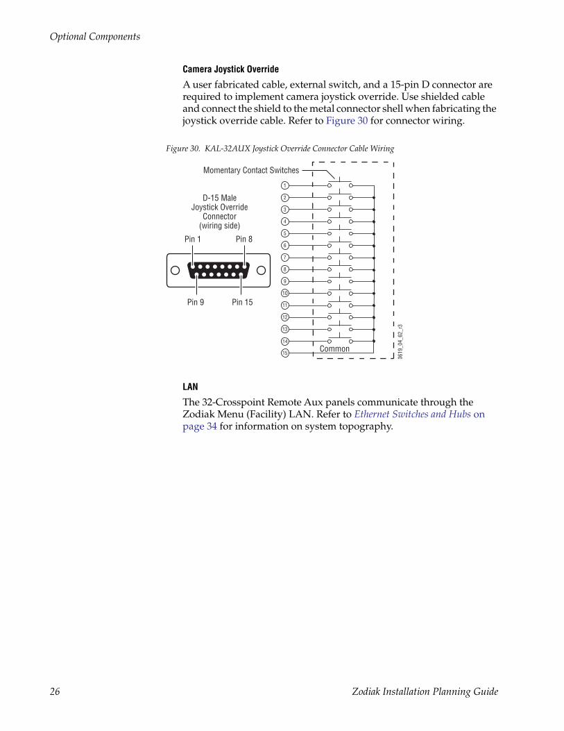
Camera Joystick Override
A user fabricated cable, external switch, and a 15-pin D connector are required to implement camera joystick override. Use shielded cable and connect the shield to the metal connector shell when fabricating the joystick override cable. Refer to Figure 30 for connector wiring.
Figure 30. KAL-32AUX Joystick Override Connector Cable Wiring
LAN
The 32-Crosspoint Remote Aux panels communicate through the Zodiak Menu (Facility) LAN. Refer to Ethernet Switches and Hubs on page 34 for information on system topography.
Common
0619
_04_
62_r
3
1
2
3
4
6
7
8
5
9
10
11
12
13
15
14
Pin 1
Pin 15Pin 9
D-15 MaleJoystick Override
Connector(wiring side)
Pin 8
Momentary Contact Switches
26 Zodiak Installation Planning Guide
Optional Components
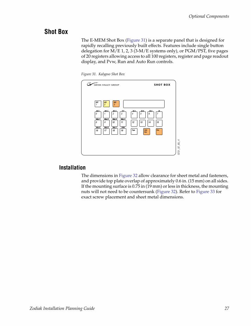
Shot BoxThe E-MEM Shot Box (Figure 31) is a separate panel that is designed for rapidly recalling previously built effects. Features include single button delegation for M/E 1, 2, 3 (3-M/E systems only), or PGM/PST, five pages of 20 registers allowing access to all 100 registers, register and page readout display, and Pvw, Run and Auto Run controls.
Figure 31. Kalypso Shot Box
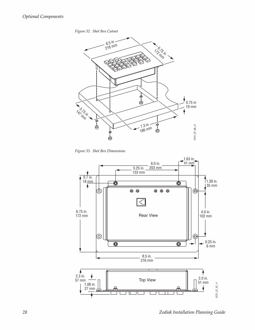
InstallationThe dimensions in Figure 32 allow clearance for sheet metal and fasteners, and provide top plate overlap of approximately 0.6 in. (15 mm) on all sides. If the mounting surface is 0.75 in (19 mm) or less in thickness, the mounting nuts will not need to be countersunk (Figure 32). Refer to Figure 33 for exact screw placement and sheet metal dimensions.
SHOT BOX
M/M/E 1 M/M/E 2 M/M/E 3 P/P/P
Misc 1Misc 1 Misc 2Misc 2 Misc 3Misc 3 Misc 4Misc 4
Misc 5Misc 5 Misc 6Misc 6 Misc 7Misc 7 DPMDPM
SS ASS A SS BSS B SS CSS C AllAll
M/EM/E
1
PagePage AutoAutoRunRun
RunRun
0 1 2 3
8 9 1010 1111
1616
4 5 6 7
1313 1414 15151212
1717 1818 1919
M/EM/E
2M/EM/E
3
0721
_07_
65_r
1
Zodiak Installation Planning Guide 27
Optional Components
Figure 32. Shot Box Cutout
Figure 33. Shot Box Dimensions
0721
_07_
66_r
2
7.3 in
186 mm
5.75 in147 mm
8.5 in
216 mm 6.75 in172 mm
0.75 in19 mm
Top View
8.5 in.216 mm
0.25 in.6 mm
4.0 in.102 mm
1.38 in.35 mm
1.63 in.41 mm
5.25 in.133 mm
8.0 in.203 mm
0.7 in.18 mm
6.75 in.172 mm
2.3 in.57 mm 2.0 in.
51 mm1.08 in.27 mm
0721
_07_
67_r
1Rear View
28 Zodiak Installation Planning Guide
Optional Components
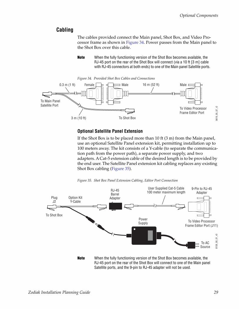
CablingThe cables provided connect the Main panel, Shot Box, and Video Pro-cessor frame as shown in Figure 34. Power passes from the Main panel to the Shot Box over this cable.
Note When the fully functioning version of the Shot Box becomes available, the RJ-45 port on the rear of the Shot Box will connect (via a 10 ft [3 m] cable with RJ-45 connectors at both ends) to one of the Main panel Satellite ports.
Figure 34. Provided Shot Box Cables and Connections
Optional Satellite Panel ExtensionIf the Shot Box is to be placed more than 10 ft (3 m) from the Main panel, use an optional Satellite Panel extension kit, permitting installation up to 100 meters away. The kit consists of a Y-cable (to separate the communica-tion path from the power path), a separate power supply, and two adapters. A Cat-5 extension cable of the desired length is to be provided by the end user. The Satellite Panel extension kit cabling replaces any existing Shot Box cabling (Figure 35).
Figure 35. Shot Box Panel Extension Cabling, Editor Port Connection
Note When the fully functioning version of the Shot Box becomes available, the RJ-45 port on the rear of the Shot Box will connect to one of the Main panel Satellite ports, and the 9-pin to RJ-45 adapter will not be used.
Male
To Video ProcessorFrame Editor Port
16 m (52 ft)
To Shot Box
To Main PanelSatellite Port
3 m (10 ft)
0619
_05_
07_r
2
0.3 m (1 ft) Female Male
To Video ProcessorFrame Editor Port (J11)
User Supplied Cat-5 Cable100 meter maximum length
8159
_00_
01_r
0To Shot Box
Option KitY-Cable
PlugJ2
9-Pin to RJ-45Adapter
RJ-45Barrel
Adapter
PowerSupply
To ACSource
Zodiak Installation Planning Guide 29
Typical Zodiak System Video Cabling
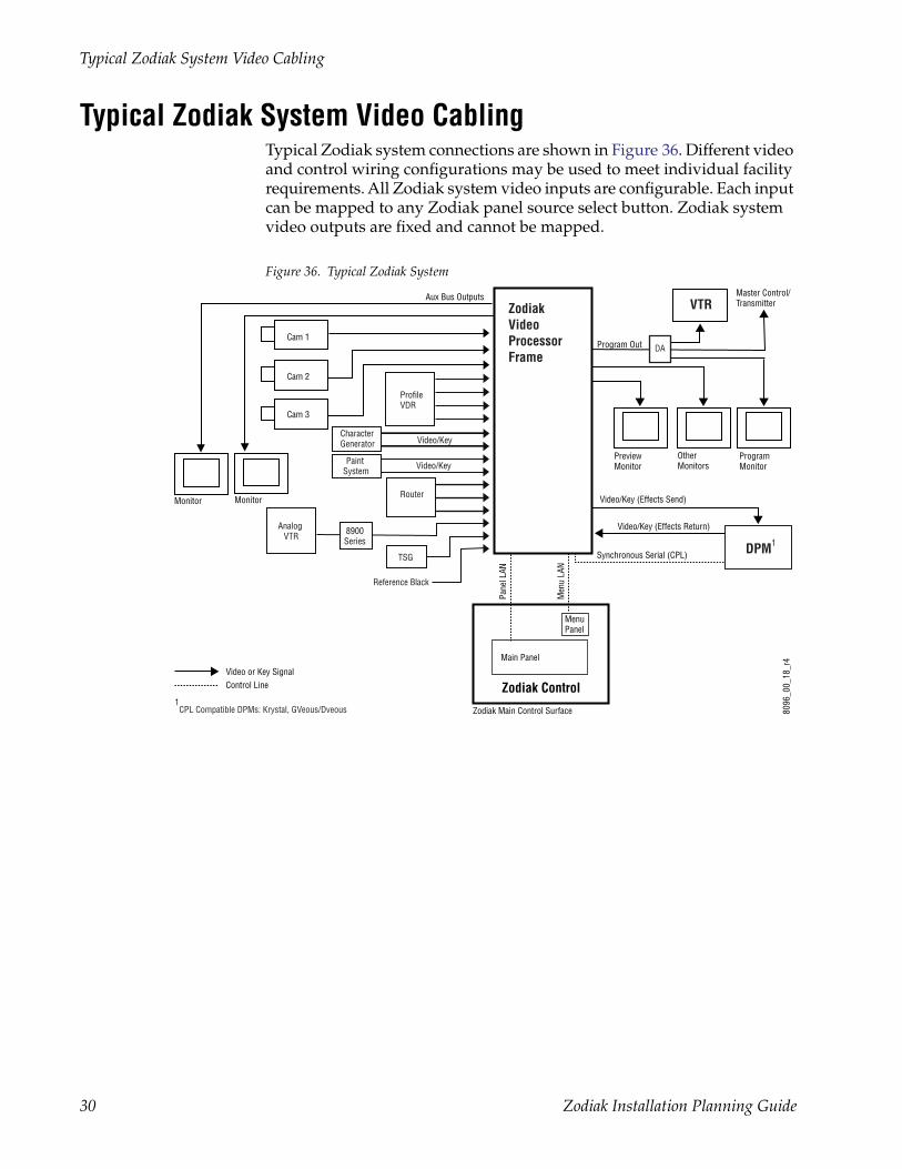
Typical Zodiak System Video CablingTypical Zodiak system connections are shown in Figure 36. Different video and control wiring configurations may be used to meet individual facility requirements. All Zodiak system video inputs are configurable. Each input can be mapped to any Zodiak panel source select button. Zodiak system video outputs are fixed and cannot be mapped.
Figure 36. Typical Zodiak System
ProgramMonitor
PreviewMonitor
OtherMonitors
Program Out
Master Control/Transmitter
Video/Key (Effects Send)
Cam 1
Cam 2
Cam 3
Video/Key (Effects Return)
Synchronous Serial (CPL)
Reference Black
Aux Bus Outputs
8096
_00_
18_r
4
Zodiak Main Control Surface
Zodiak Control
MonitorMonitor
ZodiakVideoProcessorFrame
DPM1
VTR
1CPL Compatible DPMs: Krystal, GVeous/Dveous
Video or Key SignalControl Line
MenuPanel
Main Panel
Men
u LA
N
Pane
l LAN
ProfileVDR
CharacterGenerator
Router
TSG
Paint System
Analog VTR
Video/Key
Video/Key
8900Series
DA
30 Zodiak Installation Planning Guide
Zodiak Video Timing and Delay
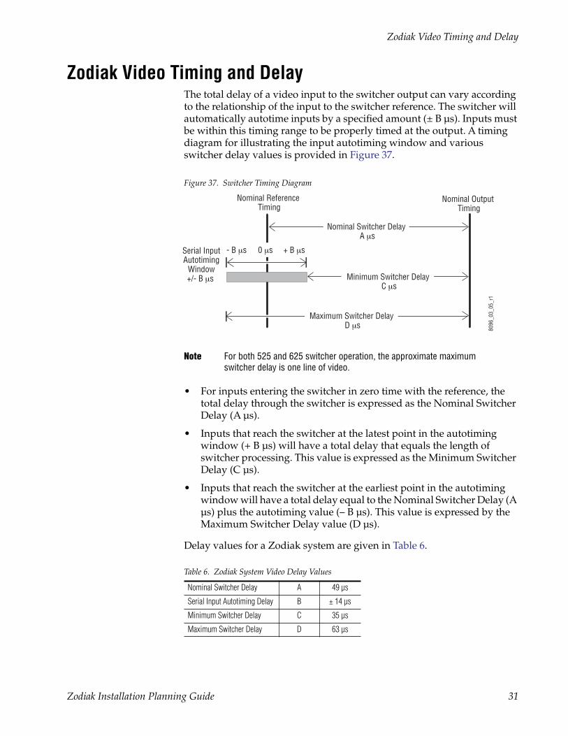
Zodiak Video Timing and DelayThe total delay of a video input to the switcher output can vary according to the relationship of the input to the switcher reference. The switcher will automatically autotime inputs by a specified amount (± B µs). Inputs must be within this timing range to be properly timed at the output. A timing diagram for illustrating the input autotiming window and various switcher delay values is provided in Figure 37.
Figure 37. Switcher Timing Diagram
Note For both 525 and 625 switcher operation, the approximate maximum switcher delay is one line of video.
• For inputs entering the switcher in zero time with the reference, the total delay through the switcher is expressed as the Nominal Switcher Delay (A µs).
• Inputs that reach the switcher at the latest point in the autotiming window (+ B µs) will have a total delay that equals the length of switcher processing. This value is expressed as the Minimum Switcher Delay (C µs).
• Inputs that reach the switcher at the earliest point in the autotiming window will have a total delay equal to the Nominal Switcher Delay (A µs) plus the autotiming value (– B µs). This value is expressed by the Maximum Switcher Delay value (D µs).
Delay values for a Zodiak system are given in Table 6.
Table 6. Zodiak System Video Delay Values
Nominal Switcher Delay A 49 µs
Serial Input Autotiming Delay B ± 14 µs
Minimum Switcher Delay C 35 µs
Maximum Switcher Delay D 63 µs
Nominal Output Timing
Serial InputAutotiming
Window+/- B µs
Nominal Reference Timing
8096
_03_
05_r
1
Nominal Switcher Delay A µs
Maximum Switcher Delay D µs
Minimum Switcher Delay C µs
- B µs + B µs0 µs
Zodiak Installation Planning Guide 31
Zodiak System Control Cabling
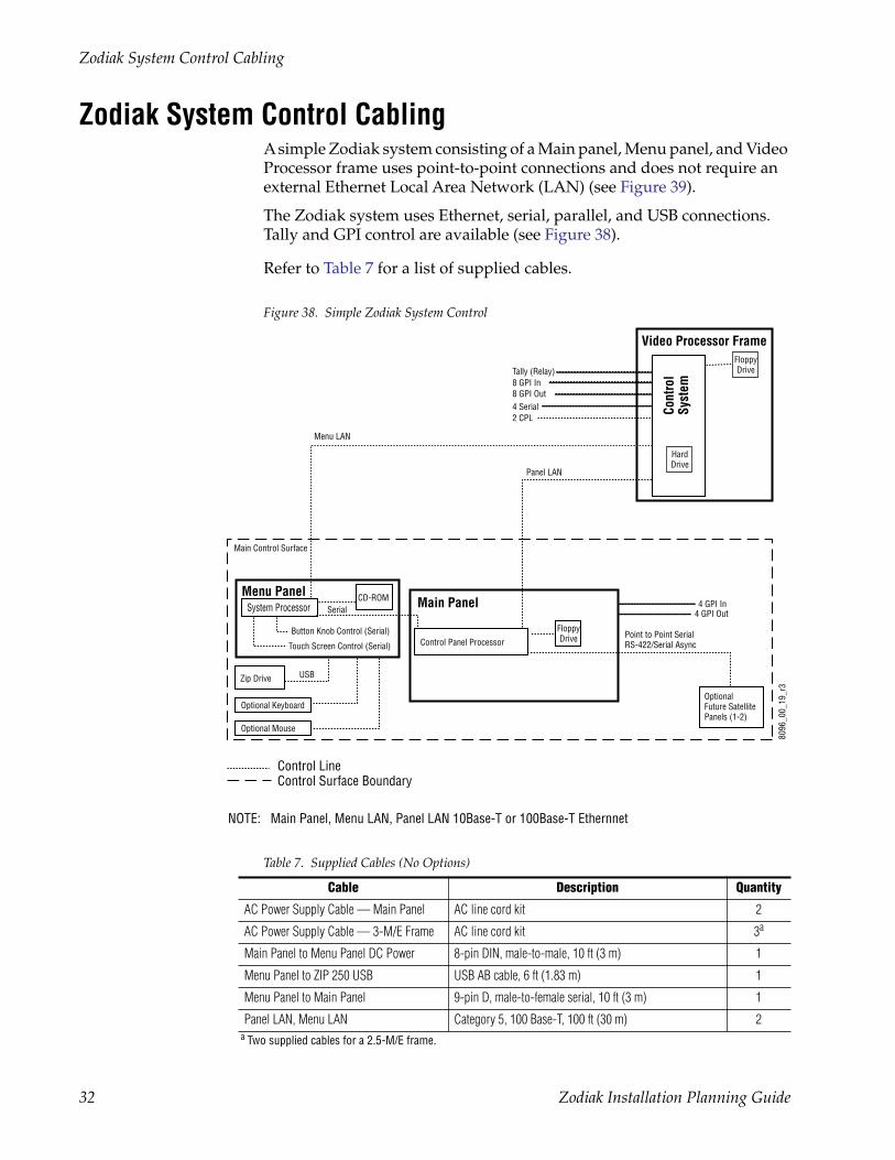
Zodiak System Control CablingA simple Zodiak system consisting of a Main panel, Menu panel, and Video Processor frame uses point-to-point connections and does not require an external Ethernet Local Area Network (LAN) (see Figure 39).
The Zodiak system uses Ethernet, serial, parallel, and USB connections. Tally and GPI control are available (see Figure 38).
Refer to Table 7 for a list of supplied cables.
Figure 38. Simple Zodiak System Control
Table 7. Supplied Cables (No Options)
Cable Description Quantity
AC Power Supply Cable — Main Panel AC line cord kit 2
AC Power Supply Cable — 3-M/E Frame AC line cord kit 3a
a Two supplied cables for a 2.5-M/E frame.
Main Panel to Menu Panel DC Power 8-pin DIN, male-to-male, 10 ft (3 m) 1
Menu Panel to ZIP 250 USB USB AB cable, 6 ft (1.83 m) 1
Menu Panel to Main Panel 9-pin D, male-to-female serial, 10 ft (3 m) 1
Panel LAN, Menu LAN Category 5, 100 Base-T, 100 ft (30 m) 2
Menu LAN
USB
Optional Keyboard
Optional Mouse
Menu Panel
Zip Drive
OptionalFuture SatellitePanels (1-2)
NOTE: Main Panel, Menu LAN, Panel LAN 10Base-T or 100Base-T Ethernnet
Main Panel
Point to Point SerialRS-422/Serial Async
8096
_00_
19_r
3
Main Control Surface
FloppyDriveControl Panel Processor
System Processor
Button Knob Control (Serial)
Touch Screen Control (Serial)
8 GPI In8 GPI Out4 Serial
Tally (Relay)
2 CPL
Video Processor Frame
Cont
rol
Syst
em
HardDrive
FloppyDrive
CD-ROM
Panel LAN
Control LineControl Surface Boundary
Serial4 GPI In
4 GPI Out
32 Zodiak Installation Planning Guide
Zodiak System Control Cabling
Cable Polarity and Cross Over ButtonsThe point-to-point connections between the Main and Menu panel(s) and the Video Processor frame require that the Transmit (TX) and Receive (RX) pairs in the Ethernet cables be swapped. This is normally achieved with a special peer-to-peer (crossover) LAN cable or an Uplink port on the switch or hub. In Zodiak systems, Cross Over buttons are provided on both the Menu panel and Main panel to allow swapping cable polarity thus elimi-nating the need for crossover cables. The LAN cables supplied with the Zodiak system are 100 ft (30 m) straight-through cables. The LAN Link LEDs at each LAN cable connector will illuminate after power up to indi-cate the connection is correct. If no communication can be established (either LAN Link LED is off), polarity can be reversed by pressing the Cross Over button on the Main and Menu panels.
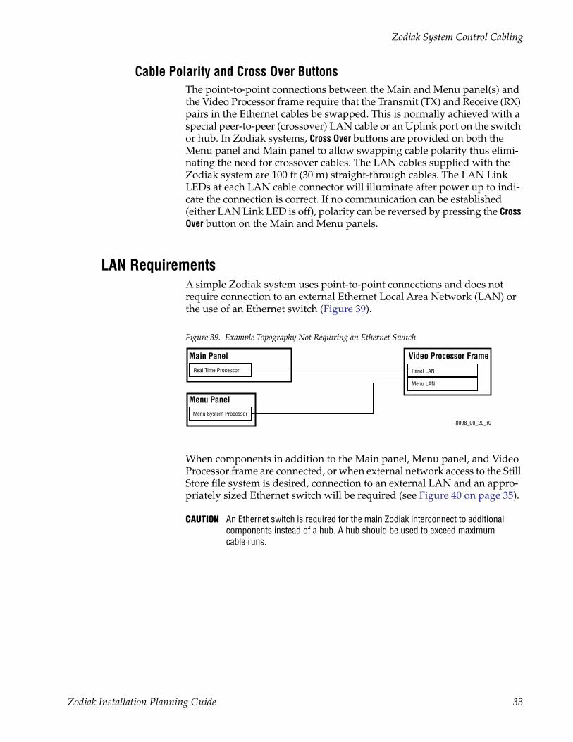
LAN RequirementsA simple Zodiak system uses point-to-point connections and does not require connection to an external Ethernet Local Area Network (LAN) or the use of an Ethernet switch (Figure 39).
Figure 39. Example Topography Not Requiring an Ethernet Switch
When components in addition to the Main panel, Menu panel, and Video Processor frame are connected, or when external network access to the Still Store file system is desired, connection to an external LAN and an appro-priately sized Ethernet switch will be required (see Figure 40 on page 35).
CAUTION An Ethernet switch is required for the main Zodiak interconnect to additional components instead of a hub. A hub should be used to exceed maximum cable runs.
8098_00_20_r0
Video Processor Frame
Panel LAN
Menu Panel
Menu System Processor
Real Time Processor
Main Panel
Menu LAN
Zodiak Installation Planning Guide 33
Zodiak System Control Cabling
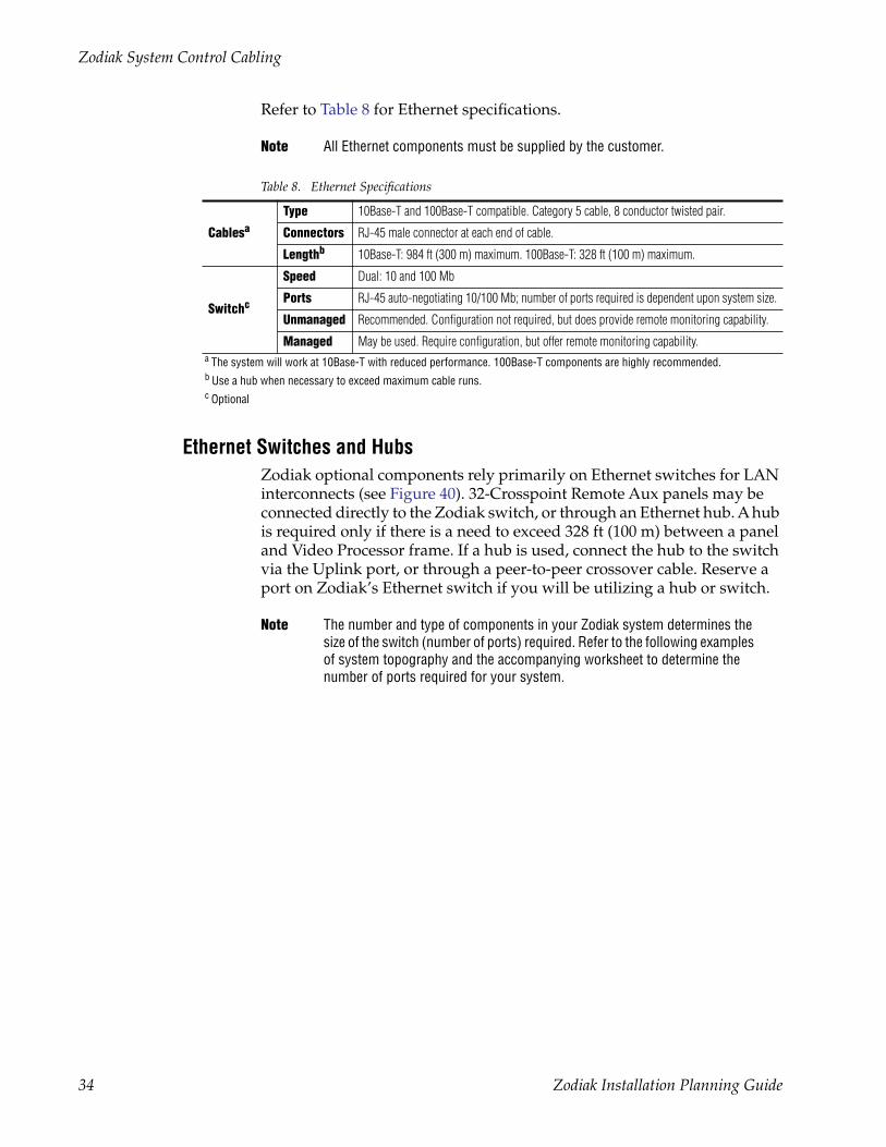
Refer to Table 8 for Ethernet specifications.
Note All Ethernet components must be supplied by the customer.
Ethernet Switches and HubsZodiak optional components rely primarily on Ethernet switches for LAN interconnects (see Figure 40). 32-Crosspoint Remote Aux panels may be connected directly to the Zodiak switch, or through an Ethernet hub. A hub is required only if there is a need to exceed 328 ft (100 m) between a panel and Video Processor frame. If a hub is used, connect the hub to the switch via the Uplink port, or through a peer-to-peer crossover cable. Reserve a port on Zodiak’s Ethernet switch if you will be utilizing a hub or switch.
Note The number and type of components in your Zodiak system determines the size of the switch (number of ports) required. Refer to the following examples of system topography and the accompanying worksheet to determine the number of ports required for your system.
Table 8. Ethernet Specifications
Cablesa
a The system will work at 10Base-T with reduced performance. 100Base-T components are highly recommended.
Type 10Base-T and 100Base-T compatible. Category 5 cable, 8 conductor twisted pair.
Connectors RJ-45 male connector at each end of cable.
Lengthb
b Use a hub when necessary to exceed maximum cable runs.
10Base-T: 984 ft (300 m) maximum. 100Base-T: 328 ft (100 m) maximum.
Switchc
c Optional
Speed Dual: 10 and 100 Mb
Ports RJ-45 auto-negotiating 10/100 Mb; number of ports required is dependent upon system size.
Unmanaged Recommended. Configuration not required, but does provide remote monitoring capability.
Managed May be used. Require configuration, but offer remote monitoring capability.
34 Zodiak Installation Planning Guide
Zodiak System Control Cabling
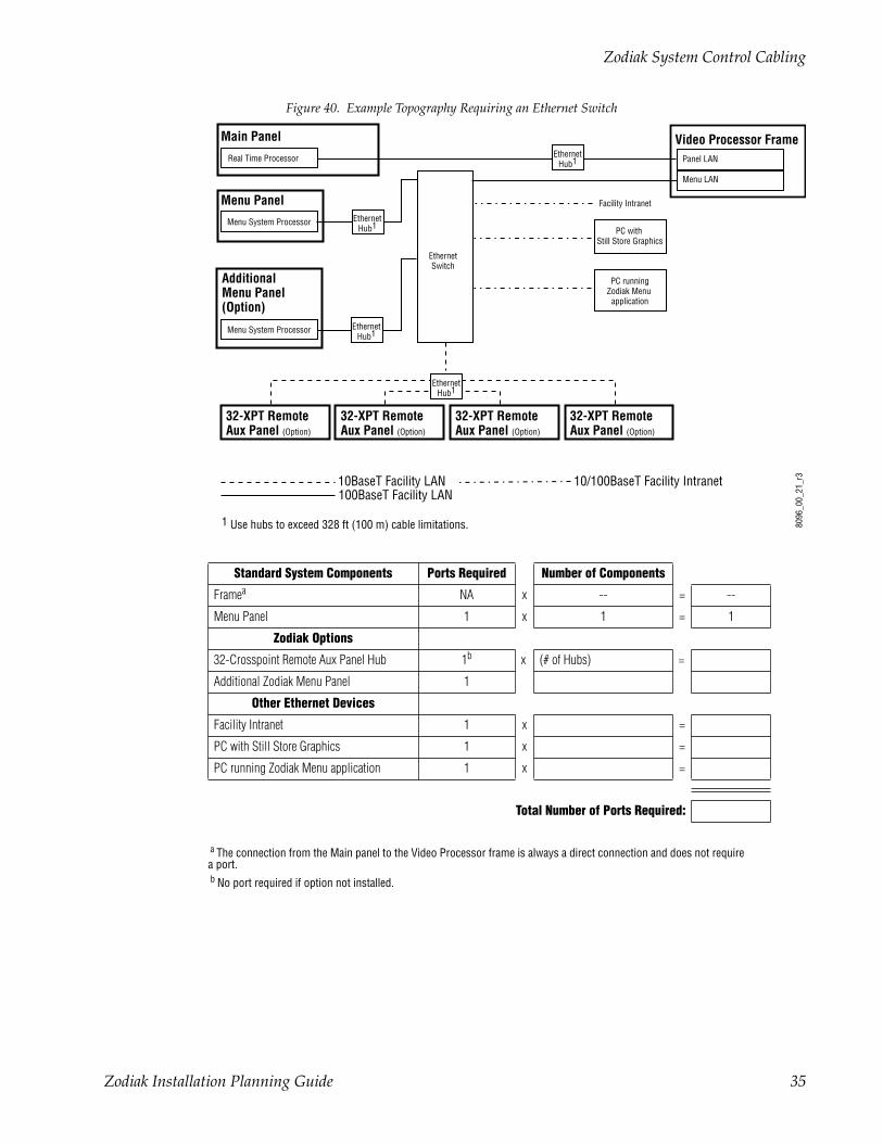
Figure 40. Example Topography Requiring an Ethernet Switch
Standard System Components Ports Required Number of Components
Framea
a The connection from the Main panel to the Video Processor frame is always a direct connection and does not requirea port.
NA x -- = --
Menu Panel 1 x 1 = 1
Zodiak Options
32-Crosspoint Remote Aux Panel Hub 1b
b No port required if option not installed.
x (# of Hubs) =
Additional Zodiak Menu Panel 1
Other Ethernet Devices
Facility Intranet 1 x =
PC with Still Store Graphics 1 x =
PC running Zodiak Menu application 1 x =
Total Number of Ports Required:
Facility Intranet
PC with Still Store Graphics
8096
_00_
21_r
3
Real Time Processor
Main Panel
10BaseT Facility LAN100BaseT Facility LAN
10/100BaseT Facility Intranet
32-XPT RemoteAux Panel (Option)
32-XPT RemoteAux Panel (Option)
32-XPT RemoteAux Panel (Option)
32-XPT RemoteAux Panel (Option)
EthernetHub1
Video Processor FramePanel LAN
1 Use hubs to exceed 328 ft (100 m) cable limitations.
Menu Panel
Menu System Processor
EthernetSwitch
EthernetHub1
EthernetHub1
Additional Menu Panel (Option)
Menu System Processor EthernetHub1
Menu LAN
PC runningZodiak Menu
application
Zodiak Installation Planning Guide 35
Pinouts
Pinouts
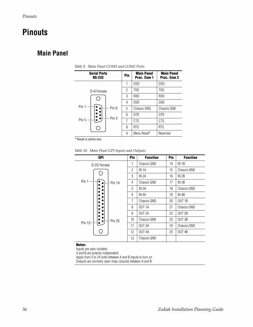
Main Panel
Table 9. Main Panel COM1 and COM2 Ports
Serial PortsRS-232 Pin Main Panel
Proc. Com 1Main Panel Proc. Com 2
1 DSD DSD
2 TXD TXD
3 RXD RXD
4 DSR DSR
5 Chassis GND Chassis GND
6 DTR DTR
7 CTS CTS
8 RTS RTS
9 Menu Reseta
a Reset is active low.
Reserved
Table 10. Main Panel GPI Inputs and Outputs
GPI Pin Function Pin Function
1 Chassis GND 14 IN 1B
2 IN 1A 15 Chassis GND
3 IN 2A 16 IN 2B
4 Chassis GND 17 IN 3B
5 IN 3A 18 Chassis GND
6 IN 4A 19 IN 4B
7 Chassis GND 20 OUT 1B
8 OUT 1A 21 Chassis GND
9 OUT 2A 22 OUT 2B
10 Chassis GND 23 OUT 3B
11 OUT 3A 24 Chassis GND
12 OUT 4A 25 OUT 4B
13 Chassis GND
Notes:Inputs are opto-isolated.A and B are polarity independent.Apply from 5 to 24 volts between A and B Inputs to turn on.Outputs are normally open relay closures between A and B.
Pin 5
Pin 6
Pin 9
D-9 Female
Pin 1
Pin 1
Pin 13
Pin 14
Pin 25
D-25 Female
36 Zodiak Installation Planning Guide
Pinouts
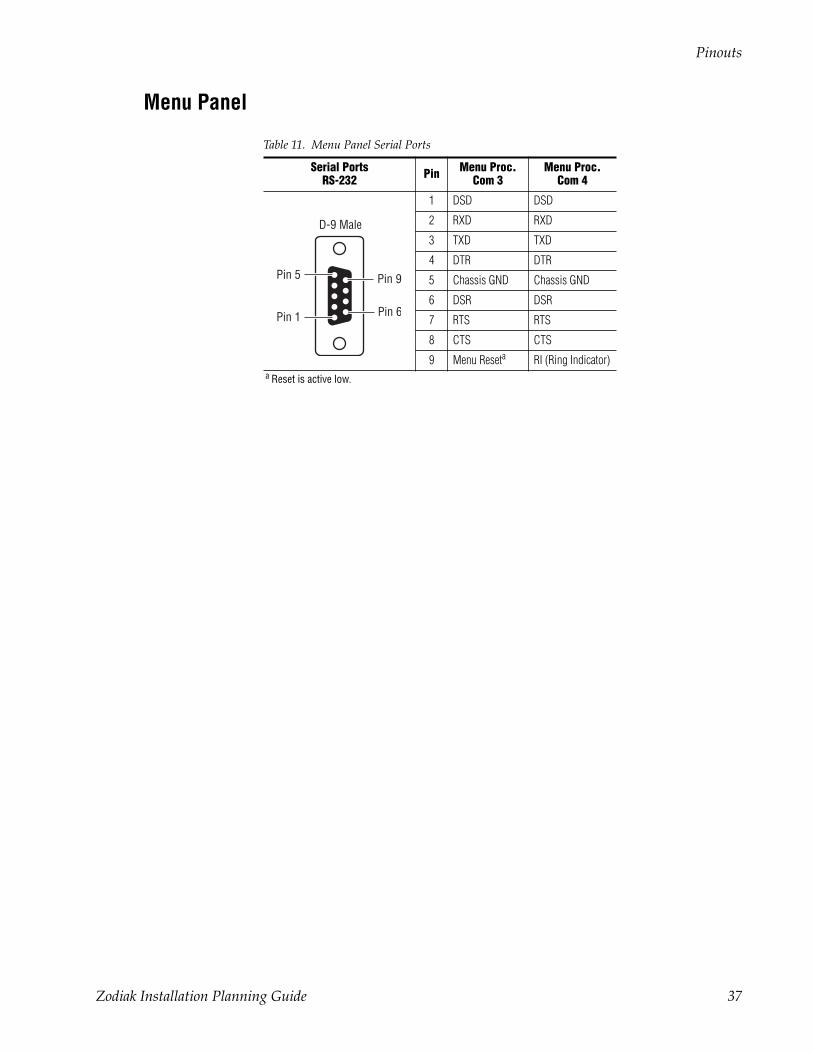
Menu Panel
Table 11. Menu Panel Serial Ports
Serial PortsRS-232 Pin Menu Proc.
Com 3Menu Proc.
Com 4
1 DSD DSD
2 RXD RXD
3 TXD TXD
4 DTR DTR
5 Chassis GND Chassis GND
6 DSR DSR
7 RTS RTS
8 CTS CTS
9 Menu Reseta
a Reset is active low.
RI (Ring Indicator)
Pin 1
Pin 9
Pin 6
D-9 Male
Pin 5
Zodiak Installation Planning Guide 37
Pinouts
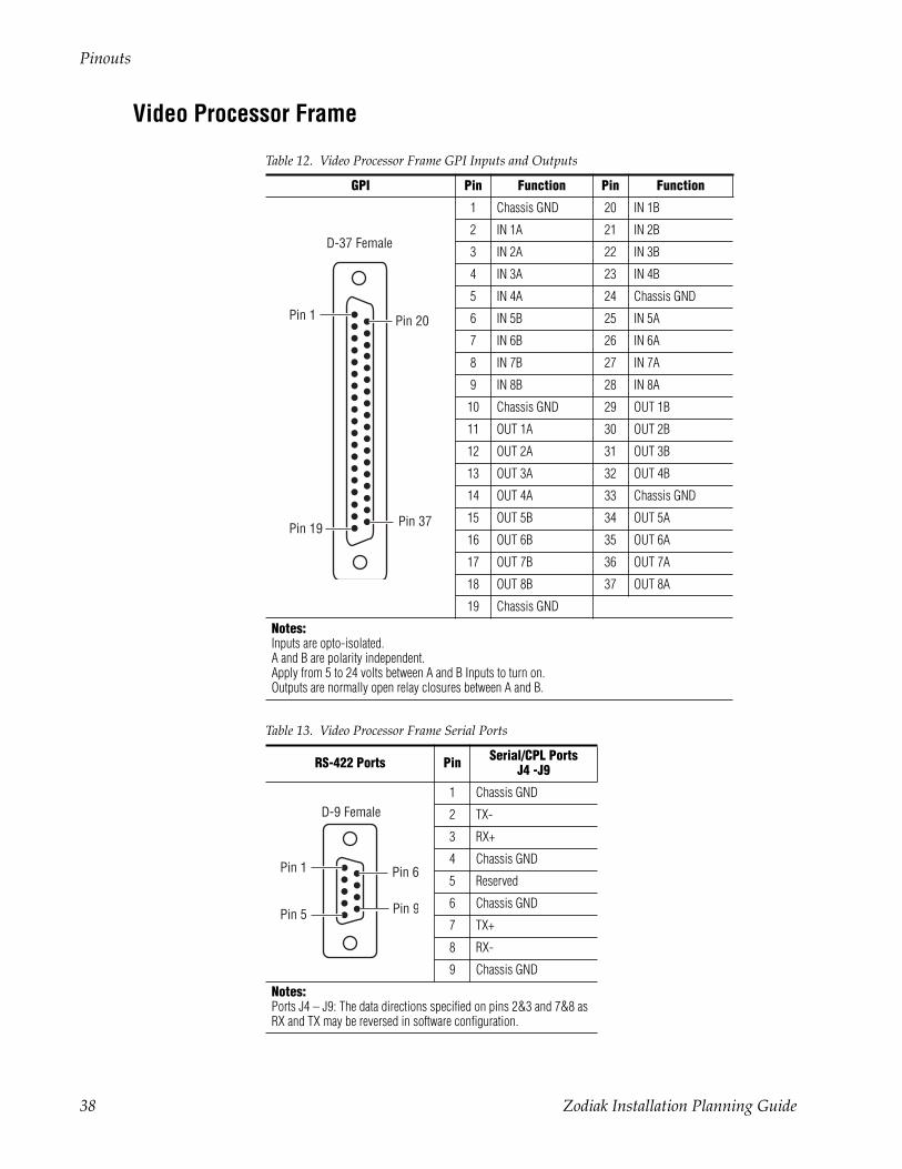
Video Processor Frame
Table 12. Video Processor Frame GPI Inputs and Outputs
GPI Pin Function Pin Function
1 Chassis GND 20 IN 1B
2 IN 1A 21 IN 2B
3 IN 2A 22 IN 3B
4 IN 3A 23 IN 4B
5 IN 4A 24 Chassis GND
6 IN 5B 25 IN 5A
7 IN 6B 26 IN 6A
8 IN 7B 27 IN 7A
9 IN 8B 28 IN 8A
10 Chassis GND 29 OUT 1B
11 OUT 1A 30 OUT 2B
12 OUT 2A 31 OUT 3B
13 OUT 3A 32 OUT 4B
14 OUT 4A 33 Chassis GND
15 OUT 5B 34 OUT 5A
16 OUT 6B 35 OUT 6A
17 OUT 7B 36 OUT 7A
18 OUT 8B 37 OUT 8A
19 Chassis GND
Notes:Inputs are opto-isolated.A and B are polarity independent.Apply from 5 to 24 volts between A and B Inputs to turn on.Outputs are normally open relay closures between A and B.
Table 13. Video Processor Frame Serial Ports
RS-422 Ports Pin Serial/CPL PortsJ4 -J9
1 Chassis GND
2 TX-
3 RX+
4 Chassis GND
5 Reserved
6 Chassis GND
7 TX+
8 RX-
9 Chassis GND
Notes:Ports J4 – J9: The data directions specified on pins 2&3 and 7&8 as RX and TX may be reversed in software configuration.
Pin 1
Pin 19
Pin 20
Pin 37
D-37 Female
Pin 5
Pin 6
Pin 9
D-9 Female
Pin 1
38 Zodiak Installation Planning Guide
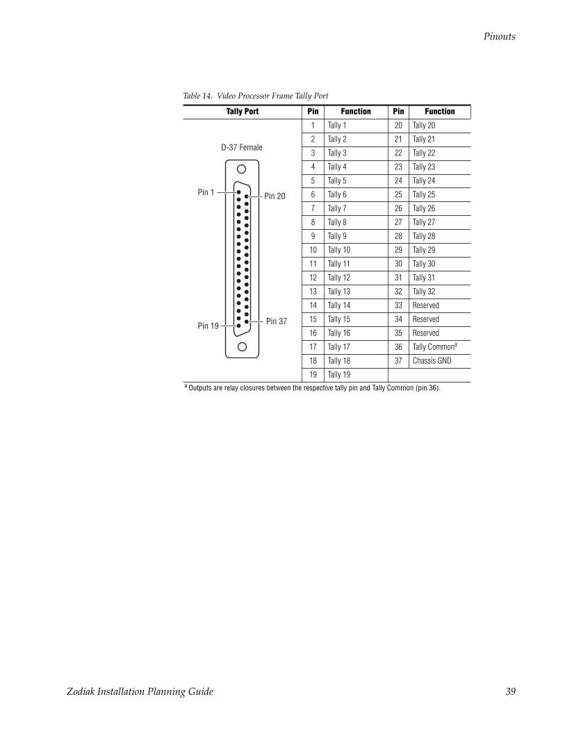
Pinouts
Table 14. Video Processor Frame Tally Port
Tally Port Pin Function Pin Function
1 Tally 1 20 Tally 20
2 Tally 2 21 Tally 21
3 Tally 3 22 Tally 22
4 Tally 4 23 Tally 23
5 Tally 5 24 Tally 24
6 Tally 6 25 Tally 25
7 Tally 7 26 Tally 26
8 Tally 8 27 Tally 27
9 Tally 9 28 Tally 28
10 Tally 10 29 Tally 29
11 Tally 11 30 Tally 30
12 Tally 12 31 Tally 31
13 Tally 13 32 Tally 32
14 Tally 14 33 Reserved
15 Tally 15 34 Reserved
16 Tally 16 35 Reserved
17 Tally 17 36 Tally Commona
a Outputs are relay closures between the respective tally pin and Tally Common (pin 36).
18 Tally 18 37 Chassis GND
19 Tally 19
Pin 1
Pin 19
Pin 20
Pin 37
D-37 Female
Zodiak Installation Planning Guide 39
Specifications
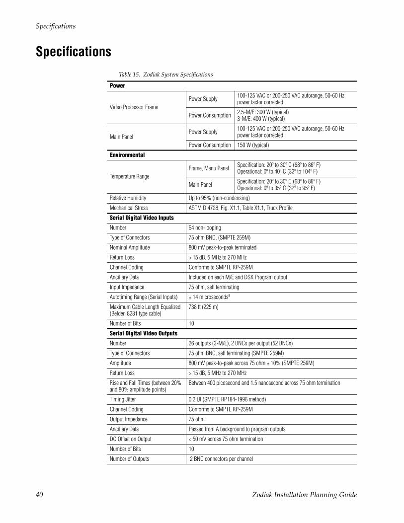
Specifications Table 15. Zodiak System Specifications
Power
Video Processor FramePower Supply 100-125 VAC or 200-250 VAC autorange, 50-60 Hz
power factor corrected
Power Consumption 2.5-M/E: 300 W (typical)3-M/E: 400 W (typical)
Main PanelPower Supply 100-125 VAC or 200-250 VAC autorange, 50-60 Hz
power factor corrected
Power Consumption 150 W (typical)
Environmental
Temperature RangeFrame, Menu Panel Specification: 20º to 30º C (68º to 86º F)
Operational: 0º to 40º C (32º to 104º F)
Main Panel Specification: 20º to 30º C (68º to 86º F)Operational: 0º to 35º C (32º to 95º F)
Relative Humidity Up to 95% (non-condensing)
Mechanical Stress ASTM D 4728, Fig. X1.1, Table X1.1, Truck Profile
Serial Digital Video Inputs
Number 64 non-looping
Type of Connectors 75 ohm BNC, (SMPTE 259M)
Nominal Amplitude 800 mV peak-to-peak terminated
Return Loss > 15 dB, 5 MHz to 270 MHz
Channel Coding Conforms to SMPTE RP-259M
Ancillary Data Included on each M/E and DSK Program output
Input Impedance 75 ohm, self terminating
Autotiming Range (Serial Inputs) ± 14 microsecondsa
Maximum Cable Length Equalized(Belden 8281 type cable)
738 ft (225 m)
Number of Bits 10
Serial Digital Video Outputs
Number 26 outputs (3-M/E), 2 BNCs per output (52 BNCs)
Type of Connectors 75 ohm BNC, self terminating (SMPTE 259M)
Amplitude 800 mV peak-to-peak across 75 ohm ± 10% (SMPTE 259M)
Return Loss > 15 dB, 5 MHz to 270 MHz
Rise and Fall Times (between 20% and 80% amplitude points)
Between 400 picosecond and 1.5 nanosecond across 75 ohm termination
Timing Jitter 0.2 UI (SMPTE RP184-1996 method)
Channel Coding Conforms to SMPTE RP-259M
Output Impedance 75 ohm
Ancillary Data Passed from A background to program outputs
DC Offset on Output < 50 mV across 75 ohm termination
Number of Bits 10
Number of Outputs 2 BNC connectors per channel
40 Zodiak Installation Planning Guide
Specifications
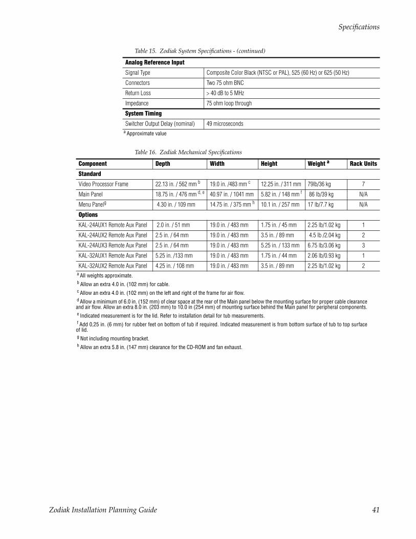
Analog Reference Input
Signal Type Composite Color Black (NTSC or PAL), 525 (60 Hz) or 625 (50 Hz)
Connectors Two 75 ohm BNC
Return Loss > 40 dB to 5 MHz
Impedance 75 ohm loop through
System Timing
Switcher Output Delay (nominal) 49 microseconds a Approximate value
Table 16. Zodiak Mechanical Specifications
Component Depth Width Height Weight a Rack Units
Standard
Video Processor Frame 22.13 in. / 562 mm b 19.0 in. /483 mm c 12.25 in. / 311 mm 79lb/36 kg 7
Main Panel 18.75 in. / 476 mm d, e 40.97 in. / 1041 mm 5.82 in. / 148 mm f 86 lb/39 kg N/A
Menu Panelg 4.30 in. / 109 mm 14.75 in. / 375 mm h 10.1 in. / 257 mm 17 lb/7.7 kg N/A
Options
KAL-24AUX1 Remote Aux Panel 2.0 in. / 51 mm 19.0 in. / 483 mm 1.75 in. / 45 mm 2.25 lb/1.02 kg 1
KAL-24AUX2 Remote Aux Panel 2.5 in. / 64 mm 19.0 in. / 483 mm 3.5 in. / 89 mm 4.5 lb /2.04 kg 2
KAL-24AUX3 Remote Aux Panel 2.5 in. / 64 mm 19.0 in. / 483 mm 5.25 in. / 133 mm 6.75 lb/3.06 kg 3
KAL-32AUX1 Remote Aux Panel 5.25 in. /133 mm 19.0 in. / 483 mm 1.75 in. / 44 mm 2.06 lb/0.93 kg 1
KAL-32AUX2 Remote Aux Panel 4.25 in. / 108 mm 19.0 in. / 483 mm 3.5 in. / 89 mm 2.25 lb/1.02 kg 2 a All weights approximate. b Allow an extra 4.0 in. (102 mm) for cable. c Allow an extra 4.0 in. (102 mm) on the left and right of the frame for air flow. d Allow a minimum of 6.0 in. (152 mm) of clear space at the rear of the Main panel below the mounting surface for proper cable clearanceand air flow. Allow an extra 8.0 in. (203 mm) to 10.0 in (254 mm) of mounting surface behind the Main panel for peripheral components. e Indicated measurement is for the lid. Refer to installation detail for tub measurements. f Add 0,25 in. (6 mm) for rubber feet on bottom of tub if required. Indicated measurement is from bottom surface of tub to top surfaceof lid. g Not including mounting bracket. h Allow an extra 5.8 in. (147 mm) clearance for the CD-ROM and fan exhaust.
Table 15. Zodiak System Specifications - (continued)
Zodiak Installation Planning Guide 41