Embed Size (px)
Citation preview
1307.7274.92 – 03
Test and Measurement Division
Technical Information
R&S® ZV-WR02 / WR03 / WR05 Calibration Kits

This technical information describes the following calibration kits: R&S® ZV-WR02 (without Sliding Match standard), stock no. 1314.5550.10 R&S® ZV-WR03 (without Sliding Match standard), stock no. 1307.7300.30 R&S® ZV-WR03 (with Sliding Match standard), stock no. 1307.7300.31 R&S® ZV-WR05 (without Sliding Match standard), stock no. 1307.8106.10 R&S® ZV-WR05 (with Sliding Match standard), stock no. 1307.8106.11
© 2010 Rohde & Schwarz GmbH & Co. KG 81671 Munich, Germany Printed in Germany – Subject to change – Data without tolerance limits is not binding. R&S® is a registered trademark of Rohde & Schwarz GmbH & Co. KG. Trade names are trademarks of the owners. The following abbreviations are used throughout this document: R&S® ZV-WR02 / -WR03 / -WR05 is abbreviated as R&S ZV-WR02 / -WR03 / -WR05

R&S® ZV-WR02 / -WR03 / -WR05 Safety Instructions
Technical Information 1307.7274.92 – 03 3
Safety Instructions The calibration kits have been designed and tested in accordance with the EC Certificate of Conformity and have left the manufacturer’s plant in a condition fully complying with safety standards.
CAUTION General safety instructions To maintain this condition and to ensure safe operation, you must observe all instructions and warnings given on this page.
Mechanical protection The calibration kits (especially the waveguide flanges) must be protected against mechanical damage. Furthermore the waveguides must be shielded from dust. While not mounted, protect the waveguide flanges by attaching the included caps. Avoid scratching the contact surfaces of the waveguide flanges. Mounting a standard The waveguide flanges of the standards are high-precision mechanical components that can be damaged by improper handling, e.g. by canting the flanges. Use a flat, stable surface for your test setup and align the flanges accurately before mounting. Opening the standards Do not disassemble the standards. This applies especially to the sliding match standard consisting of several mounted parts. The standards can be repaired only at the manufacturer's service department. Avoid heavy shocks Heavy shocks can damage internal parts of the standards. Shock-proof packing should therefore be used for storing and dispatching of the calibration kits. Use the wooden box for this purpose. Damage caused by cleaning agents Cleaning agents contain substances that may damage the standards, e.g. solvent-containing cleaning agents may damage the labeling. Never use cleaning agents such as solvents (thinners, acetone etc.), acids, bases or other substances. Protect the waveguides from any liquids. The outside of the standards is suitably cleaned using a soft, line-free dust cloth. Damage level The damage level of the calibration kits is listed in the data sheet. Exceeding this level may damage the calibration standards.
R&S® ZV-WR02 / -WR03 / -WR05 Waveguide Calibration Kits
Technical Information 1307.7274.92 – 03 4
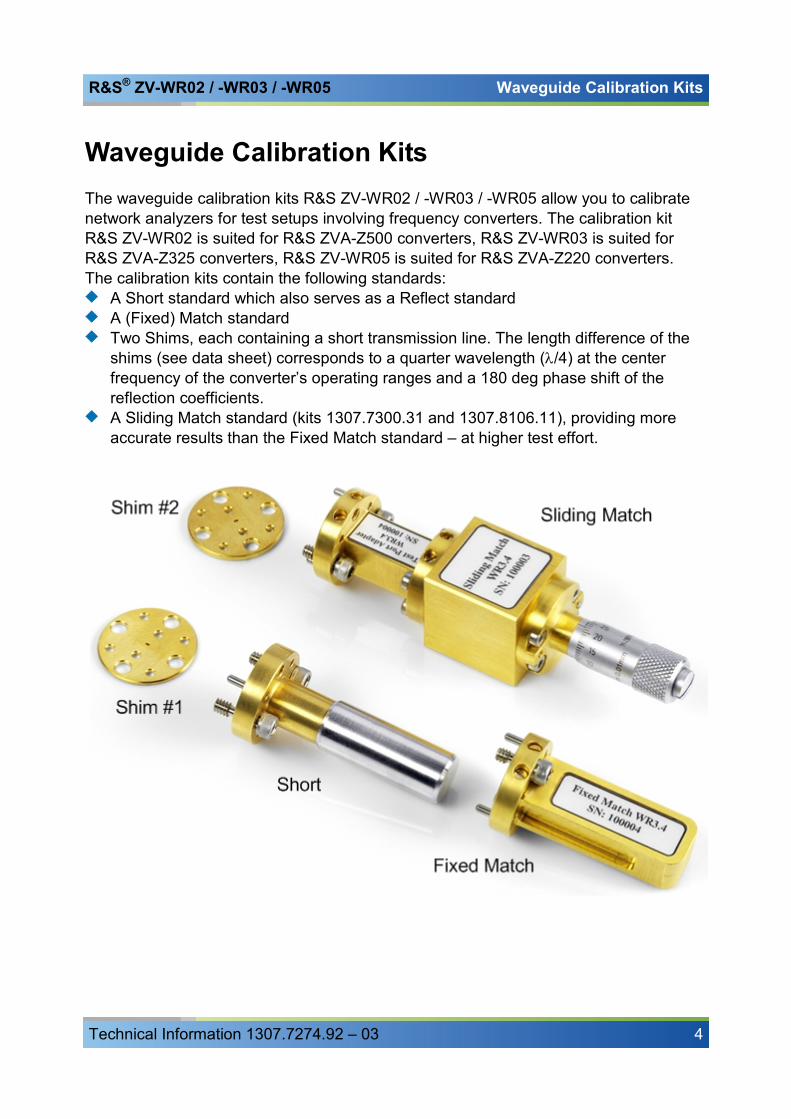
Waveguide Calibration Kits The waveguide calibration kits R&S ZV-WR02 / -WR03 / -WR05 allow you to calibrate network analyzers for test setups involving frequency converters. The calibration kit R&S ZV-WR02 is suited for R&S ZVA-Z500 converters, R&S ZV-WR03 is suited for R&S ZVA-Z325 converters, R&S ZV-WR05 is suited for R&S ZVA-Z220 converters. The calibration kits contain the following standards:
A Short standard which also serves as a Reflect standard A (Fixed) Match standard Two Shims, each containing a short transmission line. The length difference of the shims (see data sheet) corresponds to a quarter wavelength (λ/4) at the center frequency of the converter’s operating ranges and a 180 deg phase shift of the reflection coefficients. A Sliding Match standard (kits 1307.7300.31 and 1307.8106.11), providing more accurate results than the Fixed Match standard – at higher test effort.
R&S® ZV-WR02 / -WR03 / -WR05 Sliding Match Standard
Technical Information 1307.7274.92 – 03 5
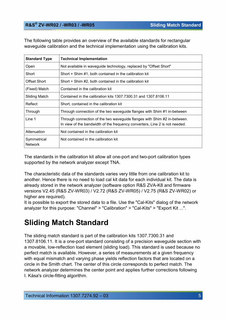
The following table provides an overview of the available standards for rectangular waveguide calibration and the technical implementation using the calibration kits. Standard Type Technical Implementation
Open Not available in waveguide technology, replaced by "Offset Short"
Short Short + Shim #1, both contained in the calibration kit
Offset Short Short + Shim #2, both contained in the calibration kit
(Fixed) Match Contained in the calibration kit
Sliding Match Contained in the calibration kits 1307.7300.31 and 1307.8106.11
Reflect Short, contained in the calibration kit
Through Through connection of the two waveguide flanges with Shim #1 in-between
Line 1 Through connection of the two waveguide flanges with Shim #2 in-between. In view of the bandwidth of the frequency converters, Line 2 is not needed.
Attenuation Not contained in the calibration kit
Symmetrical Network
Not contained in the calibration kit
The standards in the calibration kit allow all one-port and two-port calibration types supported by the network analyzer except TNA. The characteristic data of the standards varies very little from one calibration kit to another. Hence there is no need to load cal kit data for each individual kit. The data is already stored in the network analyzer (software option R&S ZVA-K8 and firmware versions V2.45 (R&S ZV-WR03) / V2.72 (R&S ZV-WR05) / V2.75 (R&S ZV-WR02) or higher are required). It is possible to export the stored data to a file. Use the "Cal-Kits" dialog of the network analyzer for this purpose: "Channel" > "Calibration" > "Cal-Kits" > "Export Kit ...".
Sliding Match Standard The sliding match standard is part of the calibration kits 1307.7300.31 and 1307.8106.11. It is a one-port standard consisting of a precision waveguide section with a movable, low-reflection load element (sliding load). This standard is used because no perfect match is available. However, a series of measurements at a given frequency with equal mismatch and varying phase yields reflection factors that are located on a circle in the Smith chart. The center of this circle corresponds to perfect match. The network analyzer determines the center point and applies further corrections following I. Kása's circle-fitting algorithm.
R&S® ZV-WR02 / -WR03 / -WR05 Performing a System Error Correction
Technical Information 1307.7274.92 – 03 6
To obtain the reflection coefficient for a perfectly matched calibration standard, the sliding load must be measured at least at three positions which should be unequally spaced to avoid overlapping data points. Increasing the number of positions to 4 – 6 can improve the accuracy. It is recommended to use the positions listed below. They are optimized for the frequency ranges of the calibration kits. Set the adjustable screw of the standard to the following positions:
R&S ZV-WR03 (220 GHz to 325 GHz): 0 mm, 0.12 mm, 0.27 mm, 0.48 mm, 0.71 mm, 1.42 mm R&S ZV-WR05 (140 GHz to 220 GHz): 0 mm, 0.18 mm, 0.41 mm, 0.72 mm, 1.07 mm, 2.15 mm
If you accidentally unscrew the knob completely, simply screw it on again.
Performing a System Error Correction Notes:
Thermal fluctuations cause linear expansion of the waveguide components and result in phase drift. An environment with a stable temperature within the range stated in the data sheet is a prerequisite for accurate measurements. A power calibration must be performed previous to system error correction. Refer to the documentation of your frequency converter for instructions. If you readjust the output power of the frequency converter (using the knurled knob at the top of the converter) an already performed system error correction is no longer valid. For that reason adjust the output power of the frequency converter before system error correction.
TRL Calibration The following example reports a TRL calibration for a four port R&S ZVA analyzer which is connected to two frequency converters. The test setup is described in the R&S ZVA-Z325 manual. It is suitable for transmission and reflection measurements on two-port waveguide DUTs in the frequency range of the converters. The calibration procedure using the analyzer’s “Calibration Wizard” is straightforward (for details refer to the analyzer help system, section “Guided Calibration”): 1. Activate the Frequency Converter Mode (“System” > “System Config…” >
“Frequency Converter”) and connect the two converters. 2. Click “Channel” > “Start Cal” > “Two Port P1 P2” > “TRL”. The calibration kit R&S ZV-WR03 is preinstalled. It is displayed in the “Select Physical VNA Test Port Connector(s)” dialog, together with the appropriate connector type.

R&S® ZV-WR02 / -WR03 / -WR05 Performing a System Error Correction
Technical Information 1307.7274.92 – 03 7
Connector type and calibration kit selection
3. Click “Next” to proceed to the “Measure Standards” dialog.
R&S® ZV-WR02 / -WR03 / -WR05 Performing a System Error Correction
Technical Information 1307.7274.92 – 03 8
4. Connect the Short standard from the calibration kit to the frequency converter no. 1 (the converter with RF IN connected to the analyzer port no. 1) and click “Port 1: WR03” > “Reflect” to initiate the calibration sweep.
5. Proceed in a similar way, using the Short at Port 2. 6. Establish the through connection using the Shim #1 between the ports. 7. Establish the line connection using the Shim #2 between the ports. 8. Click “Apply” to calculate and apply the system error correction data and close the
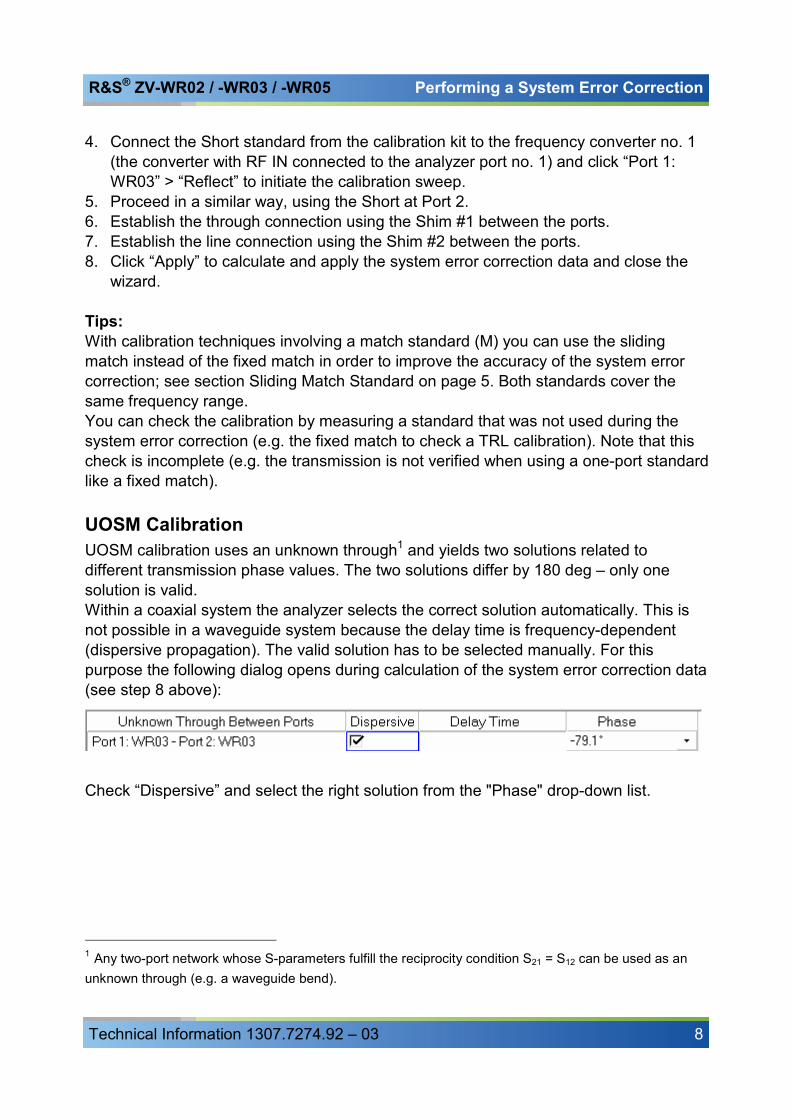
wizard. Tips: With calibration techniques involving a match standard (M) you can use the sliding match instead of the fixed match in order to improve the accuracy of the system error correction; see section Sliding Match Standard on page 5. Both standards cover the same frequency range. You can check the calibration by measuring a standard that was not used during the system error correction (e.g. the fixed match to check a TRL calibration). Note that this check is incomplete (e.g. the transmission is not verified when using a one-port standard like a fixed match). UOSM Calibration UOSM calibration uses an unknown through1 and yields two solutions related to different transmission phase values. The two solutions differ by 180 deg – only one solution is valid. Within a coaxial system the analyzer selects the correct solution automatically. This is not possible in a waveguide system because the delay time is frequency-dependent (dispersive propagation). The valid solution has to be selected manually. For this purpose the following dialog opens during calculation of the system error correction data (see step 8 above):
Check “Dispersive” and select the right solution from the "Phase" drop-down list.
1 Any two-port network whose S-parameters fulfill the reciprocity condition S21 = S12 can be used as an unknown through (e.g. a waveguide bend).