P/N 30-35202003–2006 Nissan 350Z/Infiniti G35
Manual TransmissionPlug & Play Adapter Harness
AEM Performance ElectronicsAEM Performance Electronics, 2205 126th Street Unit A, Hawthorne, CA 90250
Phone: (310) 484-2322 Fax: (310) 484-0152http://www.aemelectronics.com
Instruction Part Number: 10-3520Document Build 1/12/2015
InstructionManual
STOP!
THIS PRODUCT HAS LEGAL RESTRICTIONS. READ THIS BEFORE INSTALLING/USING!
THIS PRODUCT MAY BE USED SOLELY ON VEHICLES USED IN SANCTIONED COMPETITION WHICH MAY NEVER BE USED UPON A
PUBLIC ROAD OR HIGHWAY, UNLESS PERMITTED BY SPECIFIC REGULATORY EXEMPTION. (VISIT THE “EMISSIONS” PAGE AT HTTP://
WWW.SEMASAN.COM/EMISSIONS FOR STATE BY STATE DETAILS.)
IT IS THE RESPONSIBILITY OF THE INSTALLER AND/OR USER OF THIS PRODUCT TO ENSURE THAT IT IS USED IN COMPLIANCE WITH
ALL APPLICABLE LAWS AND REGULATIONS. IF THIS PRODUCT WAS PURCHASED IN ERROR, DO NOT INSTALL AND/OR USE IT. THE
PURCHASER MUST ARRANGE TO RETURN THE PRODUCT FOR A FULL REFUND.
THIS POLICY ONLY APPLIES TO INSTALLERS AND/OR USERS WHO ARE LOCATED IN THE UNITED STATES; HOWEVER CUSTOMERS
WHO RESIDE IN OTHER COUNTRIES SHOULD ACT IN ACCORDANCE WITH THEIR LOCAL LAWS AND REGULATIONS.
WARNING: This installation is not for the tuning novice! Use this system with EXTREME caution! The AEMInfinity Programmable EMS allows for total flexibility in engine tuning. Misuse or improper tuning of thisproduct can destroy your engine! If you are not well versed in engine dynamics and the tuning of enginemanagement systems DO NOT attempt the installation. Refer the installation to an AEM-trained tuningshop or call 800-423-0046 for technical assistance.
NOTE: All supplied AEM calibrations, Wizards and other tuning information are offered as potentialstarting points only. IT IS THE RESPONSIBILITY OF THE ENGINE TUNER TO ULTIMATELY CONFIRM IF THECALIBRATION IS SAFE FOR ITS INTENDED USE. AEM holds no responsibility for any engine damage thatresults from the misuse or mistuning of this product!
2
© 2015 AEM Performance Electronics
P/N 30-3520
OVERVIEWThis Infinity EMS kit was designed for the 2003–2006 Nissan 350Z (manual transmission), 2003–2006Infiniti G35 (manual transmission). The kit is “plug and play” so no cutting or splicing is necessary. Thebase configuration files available for the Infinity ECU are starting points only and will need to be modifiedfor your specific application.
Included in these instructions are descriptions of important differences between using the factory Nissan/Infiniti ECU and using the AEM Infinity ECU. For example, the cruise control feature is not supportedwith the AEM Infinity, but the cruise control buttons are available for miscellaneous inputs such as hi/lowboost, traction control, 2-step rev limiter, etc.
NOTE: The Flash Enable connector (described in page-11) MUST be “jumped” in order toconnect to the Infinity and load the initial firmware file. Subsequent firmware upgrades will notrequire this step. -Ignition key OFF -Insert zip-tied jumper shunt connector into Flash Enable connector -Ignition key ON (RUN position) -Infinity Tuner | Target | Upgrade Firmware… | Upload downloaded .pakgrp file -Disconnect Flash Enable jumper connector -Infinity Tuner | File | Import Calibration Data | Select appropriate base session file
GETTING STARTEDRefer to the 10-7100 for EMS 30-7100 Infinity Quick Start Guide for additional information on gettingthe engine started with the Infinity EMS. Nissan 350Z and Infiniti G35 base sessions are located in C:\Documents\AEM\Infinity Tuner\Sessions\Base Sessions
DOWNLOADABLE FILESFiles can be downloaded from www.aeminfinity.com. An experienced tuner must be available to configureand manipulate the data before driving can commence. The Quick Start Guide and Full Manual describethe steps for logging in and registering at www.aeminfinity.com. These documents are available fordownload in the Support section of the AEM Electronics website: http://www.aemelectronics.com/products/support/instructions
Downloadable files for Nissan 350Z and Infiniti G357107-XXXX-66 Infinity-10 Nissan 350Z (XXXX = serial number) 7110-XXXX-67 Infinity-8 Nissan 350Z (XXXX = serial number)
OPTIONS30-2001 UEGO Wideband O2 SensorBosch LSU4.2 Wideband O2 Sensor that connects to AEM 30-3600 UEGO Wideband O2 SensorExtension Harness
30-3600 UEGO Wideband O2 Sensor Extension HarnessExtension harness to connect AEM UEGO Wideband O2 sensor to 6-pin Deutsch
30-3602 IP67 Logging CableUSB A-to-A extension cable: 39” long with right angled connector and bayonet style lock
2003–2006 Nissan 350Z/Infiniti G35 3
© 2015 AEM Performance Electronics
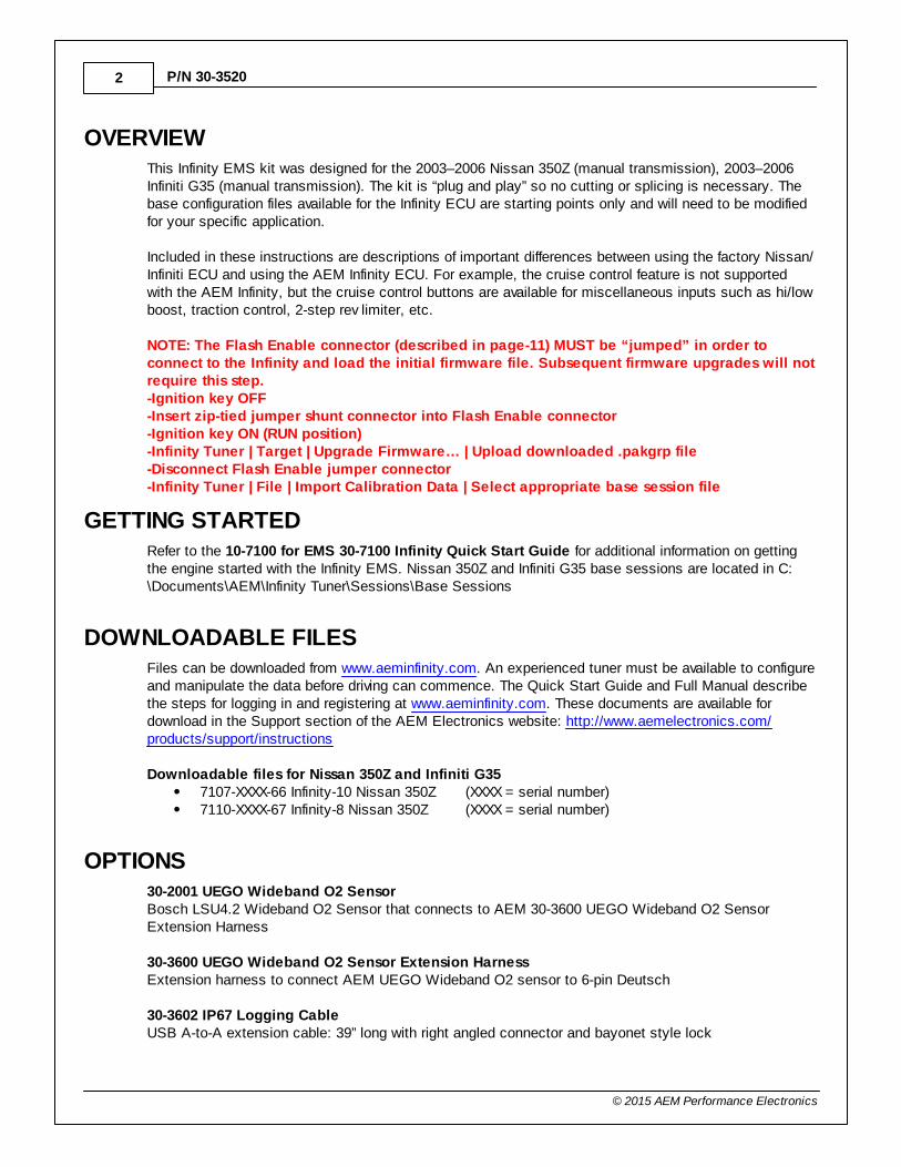
INFINITY CONNECTORSThe AEM Infinity EMS uses the MX123 Sealed Connection Systemfrom Molex. AEM strongly recommends that users become familiarwith the proper tools and procedures for working with these highdensity connectors before attempting any modifications. The entireMolex MX123 User Manual can be downloaded direct from Molex at:
http://www.molex.com/mx_upload/family//MX123UserManual.pdf
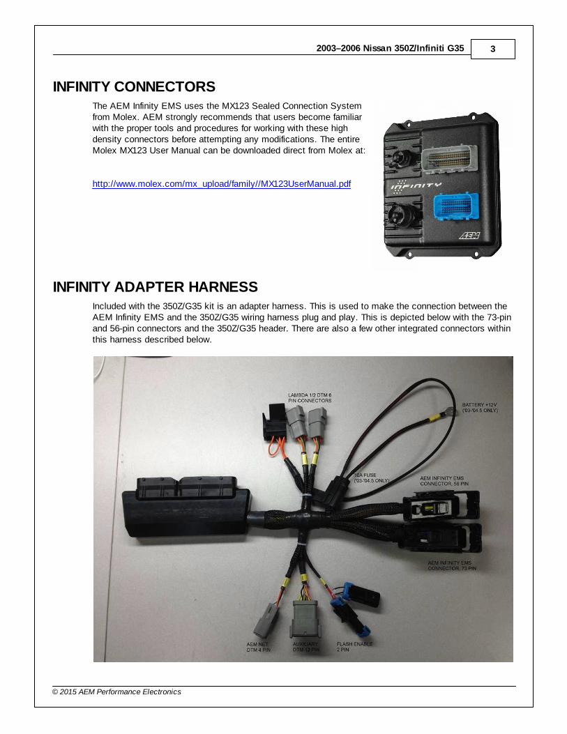
INFINITY ADAPTER HARNESSIncluded with the 350Z/G35 kit is an adapter harness. This is used to make the connection between theAEM Infinity EMS and the 350Z/G35 wiring harness plug and play. This is depicted below with the 73-pinand 56-pin connectors and the 350Z/G35 header. There are also a few other integrated connectors withinthis harness described below.
4
© 2015 AEM Performance Electronics
P/N 30-3520
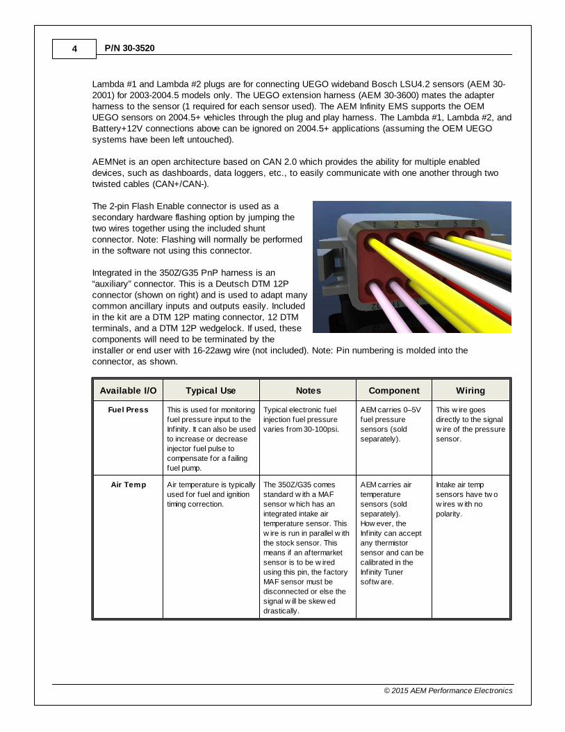
Lambda #1 and Lambda #2 plugs are for connecting UEGO wideband Bosch LSU4.2 sensors (AEM 30-2001) for 2003-2004.5 models only. The UEGO extension harness (AEM 30-3600) mates the adapterharness to the sensor (1 required for each sensor used). The AEM Infinity EMS supports the OEMUEGO sensors on 2004.5+ vehicles through the plug and play harness. The Lambda #1, Lambda #2, andBattery+12V connections above can be ignored on 2004.5+ applications (assuming the OEM UEGOsystems have been left untouched).
AEMNet is an open architecture based on CAN 2.0 which provides the ability for multiple enableddevices, such as dashboards, data loggers, etc., to easily communicate with one another through twotwisted cables (CAN+/CAN-).
The 2-pin Flash Enable connector is used as asecondary hardware flashing option by jumping thetwo wires together using the included shuntconnector. Note: Flashing will normally be performedin the software not using this connector.
Integrated in the 350Z/G35 PnP harness is an“auxiliary” connector. This is a Deutsch DTM 12Pconnector (shown on right) and is used to adapt manycommon ancillary inputs and outputs easily. Includedin the kit are a DTM 12P mating connector, 12 DTMterminals, and a DTM 12P wedgelock. If used, thesecomponents will need to be terminated by theinstaller or end user with 16-22awg wire (not included). Note: Pin numbering is molded into theconnector, as shown.
Available I/O Typical Use Notes Component Wiring
Fuel Press This is used for monitoring
fuel pressure input to the
Infinity. It can also be used
to increase or decrease
injector fuel pulse to
compensate for a failing
fuel pump.
Typical electronic fuel
injection fuel pressure
varies from 30-100psi.
AEM carries 0–5V
fuel pressure
sensors (sold
separately).
This w ire goes
directly to the signal
w ire of the pressure
sensor.
Air Temp Air temperature is typically
used for fuel and ignition
timing correction.
The 350Z/G35 comes
standard w ith a MAF
sensor w hich has an
integrated intake air
temperature sensor. This
w ire is run in parallel w ith
the stock sensor. This
means if an aftermarket
sensor is to be w ired
using this pin, the factory
MAF sensor must be
disconnected or else the
signal w ill be skew ed
drastically.
AEM carries air
temperature
sensors (sold
separately).
How ever, the
Infinity can accept
any thermistor
sensor and can be
calibrated in the
Infinity Tuner
softw are.
Intake air temp
sensors have tw o
w ires w ith no
polarity.
2003–2006 Nissan 350Z/Infiniti G35 5
© 2015 AEM Performance Electronics
Available I/O Typical Use Notes Component Wiring
Sensor Ground Isolated ground for
inputs.
This is not the same as a
pow er ground or chassis
ground.
This is shared for
the Fuel Press,
Air Temp, MAP
(Manifold Press),
Ethanol Sensor,
etc.
This should be w ired
to the ground pin of
the follow ing: Fuel
Press, Air Temp,
MAP, and Ethanol
Sensor.
5V Reference 5 volt supply for the
follow ing aux inputs.
When measured w ith a
voltmeter, it is normal to
not measure exactly 5V.
This is shared for
the Fuel Press,
MAP (Manifold
Press), and
Ethanol Sensor
inputs.
This should be w ired
to the voltage
reference pin of the
follow ing: Fuel
Press, MAP, and
Ethanol Sensor.
MAP (Manifold
Press)
Manifold pressure is used
for speed density fuel
calculation, ignition timing
correction, 02 feedback,
boost control, variable
valve control, ancillary
outputs, etc.
Electronic fuel injection is
calculated in absolute
pressure not gauge
pressure.
AEM carries MAP
sensors (sold
separately).
How ever, the
Infinity can accept
any 0–5V pressure
sensor and can be
calibrated in the
Infinity Tuner
softw are.
This should be w ired
directly to the MAP
sensor's signal pin.
Ethanol Sensor This is used for
customers w ho are
converting their vehicle to
utilize ethanol fuels such
as E85 or E98.
This digital input can be
used for other functions
as w ell.
The GM Fuel
Composition Sensor
(FCS) is the most
commonly used for
converting a vehicle
to f lex fuel.
This pin needs to be
w ired directly to the
signal pin of the fuel
composition sensor.
Boost Control
Solenoid
This is used to operate a
12V PWM solenoid.
Boost control solenoids
can be normally open (NO)
or normally closed (NC).
This w ill change the duty
cycle strategy but is also
depends upon how the
w astegate is plumbed
w ith hoses.
AEM carries boost
control solenoids
(sold separately).
How ever, the
Infinity can control
most factory boost
control solenoids.
Solenoids have tw o
w ires and have no
polarity.
Power from
Relay
Can be used for many
things, how ever, this 12V
source w as implemented
to be paired w ith the
Boost Control
Solenoid.
This 12V is coming
through the vehicle's main
relay.
Because of using
shared pow er, this
should only be used
for low current
electronics.
N/A
High Side
Output
Can be used to activate
the 12V side of a solenoid
If attempting to drive a
component over 4amps, a
relay must be used.
The Infinity can
directly drive an
electronic
component up to
4amps max, such
as a boost solenoid.
For a relay, this
should be w ired to
terminal 86 (or 85).
Supply chassis
ground to the
opposite terminal 85
(or 86). If directly
driving a low current
component, w ire this
to the 12V terminal.
6
© 2015 AEM Performance Electronics
P/N 30-3520
Available I/O Typical Use Notes Component Wiring
Boost Target
Trim Selector
Input
Can be used for to trigger
multiple boost targets.
This analog input can be
used for other functions
as w ell.
AEM 12 Position
Universal Trim Pot
(or typical
potentiometer). Can
also be used w ith
any simple ON/OFF
sw itch.
This w ire should be
routed to the signal
output of the
component. If used
w ith a simple ON/
OFF sw itch, route
the opposite terminal
to an Infinity sensor
ground.
Oil
Temperature
Oil temperature is typically
used for engine protection
and logging.
This analog input can be
used for other functions
as w ell.
AEM carries
temperature
sensors (sold
separately).
How ever, the
Infinity can accept
any thermistor
sensor and can be
calibrated in the
Infinity Tuner
softw are.
Intake air temp
sensors have tw o
w ires w ith no
polarity.
No Lift Shift
Trigger
Cutting fuel and/or cutting
spark and/or retarding
ignition timing w hen
shifting gears w ithout
releasing the throttle
pedal.
Cut time is typically 200–300mS. Ignition retard is
typically 20degree w ith a
50mS ramp-in time after
the fuel cut. Ignition cut is
not commonly used.
AEM 12 Position
Universal Trim Pot
(or typical
potentiometer). Can
also be used w ith
any simple ON/OFF
sw itch.
This w ire should be
routed to the signal
output of the
component. If used
w ith a simple ON/
OFF sw itch, route
the opposite terminal
to an Infinity sensor
ground.
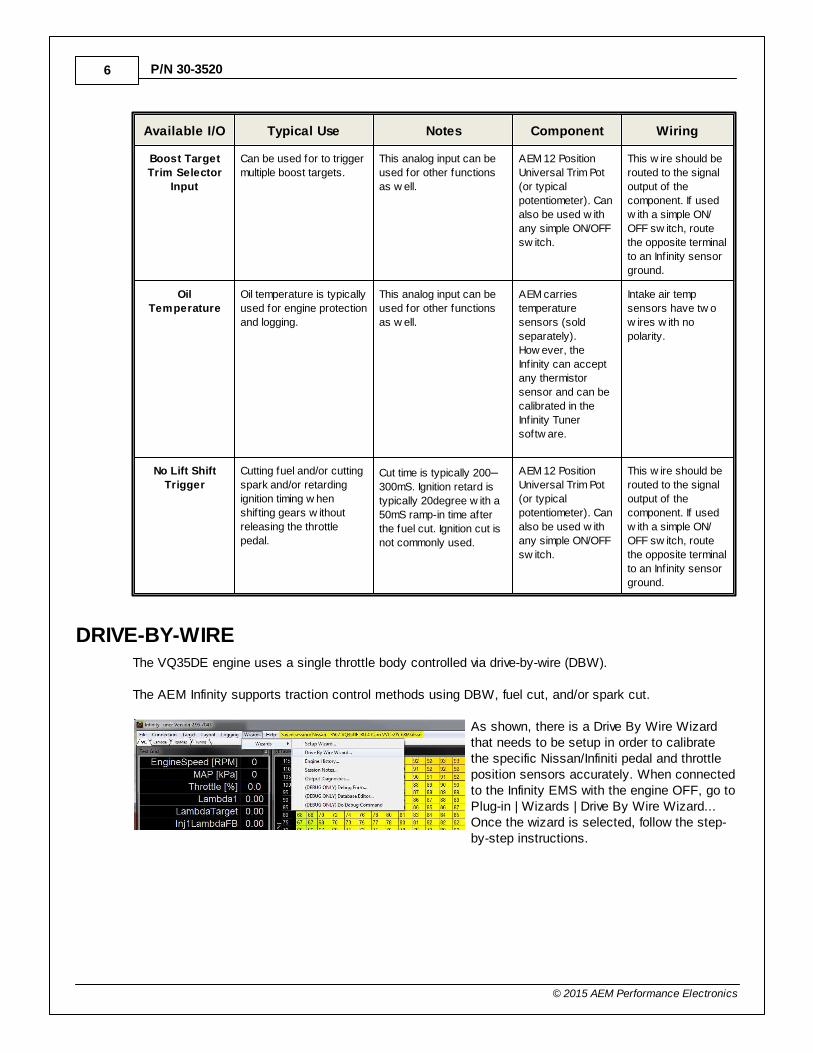
DRIVE-BY-WIREThe VQ35DE engine uses a single throttle body controlled via drive-by-wire (DBW).
The AEM Infinity supports traction control methods using DBW, fuel cut, and/or spark cut.
As shown, there is a Drive By Wire Wizardthat needs to be setup in order to calibratethe specific Nissan/Infiniti pedal and throttleposition sensors accurately. When connectedto the Infinity EMS with the engine OFF, go toPlug-in | Wizards | Drive By Wire Wizard...Once the wizard is selected, follow the step-by-step instructions.
2003–2006 Nissan 350Z/Infiniti G35 7
© 2015 AEM Performance Electronics
Note that there is also a DBW Tuningsection in the Plug-in | Wizards | SetupWizard… However, most of thechannels in here will already be set upproperly from the AEM base sessionfile.
There are a few integrated DBW failsafes incorporated into the Infinity system. For instance, if the accelerator pedal and throttle positionsensors do not track each other, or if the maximum DBW current is exceeded, there will be a fatal errorwhich will kill the engine for safety purposes. If the fatal error triggers, the AEM Infinity notifies the driverby illuminating the Engine Malfunction Lamp (EML). This error will reset when the ignition key is cycledor if the problem is fixed.
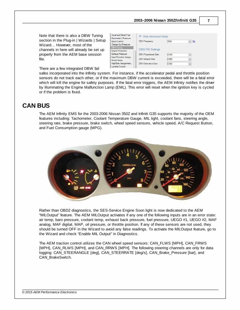
CAN BUSThe AEM Infinity EMS for the 2003-2006 Nissan 350Z and Infiniti G35 supports the majority of the OEMfeatures including: Tachometer, Coolant Temperature Gauge, MIL light, coolant fans, steering angle,steering rate, brake pressure, brake switch, wheel speed sensors, vehicle speed, A/C Request Button,and Fuel Consumption gauge (MPG).
Rather than OBD2 diagnostics, the SES-Service Engine Soon light is now dedicated to the AEM“MILOutput” feature. The AEM MILOutput activates if any one of the following inputs are in an error state:air temp, baro pressure, coolant temp, exhaust back pressure, fuel pressure, UEGO #1, UEGO #2, MAFanalog, MAF digital, MAP, oil pressure, or throttle position. If any of these sensors are not used, theyshould be turned OFF in the Wizard to avoid any false readings. To activate the MILOutput feature, go tothe Wizard and check “Enable MIL Output” in Diagnostics.
The AEM traction control utilizes the CAN wheel speed sensors: CAN_FLWS [MPH], CAN_FRWS[MPH], CAN_RLWS [MPH], and CAN_RRWS [MPH]. The following steering channels are only for datalogging: CAN_STEERANGLE [deg], CAN_STEERRATE [deg/s], CAN_Brake_Pressure [bar], andCAN_BrakeSwitch.
8
© 2015 AEM Performance Electronics
P/N 30-3520
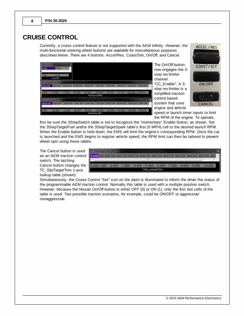
CRUISE CONTROLCurrently, a cruise control feature is not supported with the AEM Infinity. However, themulti-functional steering wheel buttons are available for miscellaneous purposesdescribed below. There are 4 buttons: Accel/Res, Coast/Set, On/Off, and Cancel.
The On/Off buttonnow engages the 3-step rev limiterchannel“CC_Enable”. A 3-step rev limiter is asimplified tractioncontrol basedsystem that usesengine and vehiclespeed or launch timer inputs to limitthe RPM of the engine. To operate,
first be sure the 3StepSwitch table is set to recognize the “momentary” Enable button, as shown. Setthe 3StepTargetFuel and/or the 3StepTargetSpark table’s first (0 MPH) cell to the desired launch RPM.When the Enable button is held down, the EMS will limit the engine’s corresponding RPM. Once the caris launched and the EMS begins to register vehicle speed, the RPM limit can then be tailored to preventwheel spin using these tables.
The Cancel button is usedas an AEM traction controlswitch. The latchingCancel button changes theTC_SlipTargetTrim 1-axislookup table (shown).Simultaneously, the Cruise Control “Set” icon on the dash is illuminated to inform the driver the status ofthe programmable AEM traction control. Normally this table is used with a multiple position switch.However, because the Nissan On/Off button is either OFF (0) or ON (1), only the first two cells of thetable is used. Two possible traction scenarios, for example, could be ON/OFF or aggressive/nonaggressive.
2003–2006 Nissan 350Z/Infiniti G35 9
© 2015 AEM Performance Electronics
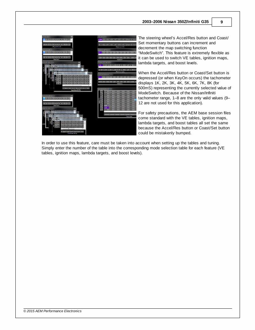
The steering wheel’s Accel/Res button and Coast/Set momentary buttons can increment anddecrement the map switching function“ModeSwitch”. This feature is extremely flexible asit can be used to switch VE tables, ignition maps,lambda targets, and boost levels.
When the Accel/Res button or Coast/Set button isdepressed (or when KeyOn occurs) the tachometerdisplays 1K, 2K, 3K, 4K, 5K, 6K, 7K, 8K (for500mS) representing the currently selected value ofModeSwitch. Because of the Nissan/Infinititachometer range, 1–8 are the only valid values (9–12 are not used for this application).
For safety precautions, the AEM base session filescome standard with the VE tables, ignition maps,lambda targets, and boost tables all set the samebecause the Accel/Res button or Coast/Set buttoncould be mistakenly bumped.
In order to use this feature, care must be taken into account when setting up the tables and tuning.Simply enter the number of the table into the corresponding mode selection table for each feature (VEtables, ignition maps, lambda targets, and boost levels).
10
© 2015 AEM Performance Electronics
P/N 30-3520
VARIABLE VALVE CONTROL (VVC)The AEM Infinity system supports Nissan’s 2 cam variable valve timing equipped engines (VQ35DE) and4 cam variable valve timing equipped engines (VQ35DE-RU). The base calibration is configured with baseVVC settings that may need adjustment.
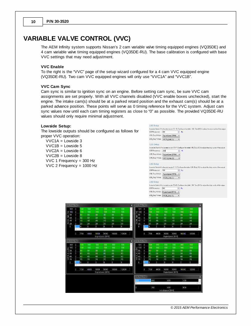
VVC EnableTo the right is the “VVC” page of the setup wizard configured for a 4 cam VVC equipped engine(VQ35DE-RU). Two cam VVC equipped engines will only use “VVC1A” and “VVC1B”.
VVC Cam SyncCam sync is similar to ignition sync on an engine. Before setting cam sync, be sure VVC camassignments are set properly. With all VVC channels disabled (VVC enable boxes unchecked), start theengine. The intake cam(s) should be at a parked retard position and the exhaust cam(s) should be at aparked advance position. These points will serve as 0 timing reference for the VVC system. Adjust camsync values now until each cam timing registers as close to “0” as possible. The provided VQ35DE-RUvalues should only require minimal adjustment.
Lowside Setup:The lowside outputs should be configured as follows forproper VVC operation: VVC1A = Lowside 3 VVC1B = Lowside 5 VVC2A = Lowside 6 VVC2B = Lowside 8 VVC 1 Frequency = 300 Hz VVC 2 Frequency = 1000 Hz
2003–2006 Nissan 350Z/Infiniti G35 11
© 2015 AEM Performance Electronics
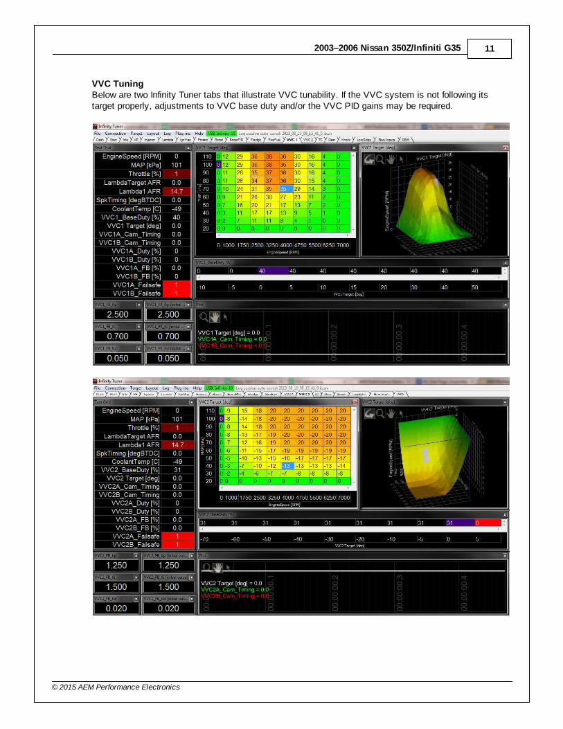
VVC TuningBelow are two Infinity Tuner tabs that illustrate VVC tunability. If the VVC system is not following itstarget properly, adjustments to VVC base duty and/or the VVC PID gains may be required.
12
© 2015 AEM Performance Electronics
P/N 30-3520
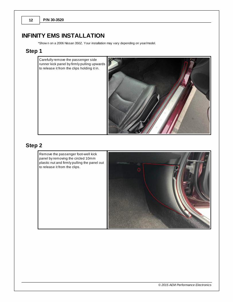
INFINITY EMS INSTALLATION*Show n on a 2006 Nissan 350Z. Your installation may vary depending on year/model.
Step 1
Carefully remove the passenger siderunner kick panel by firmly pulling upwardsto release it from the clips holding it in.
Step 2
Remove the passenger foot-well kickpanel by removing the circled 10mmplastic nut and firmly pulling the panel outto release it from the clips.
2003–2006 Nissan 350Z/Infiniti G35 13
© 2015 AEM Performance Electronics
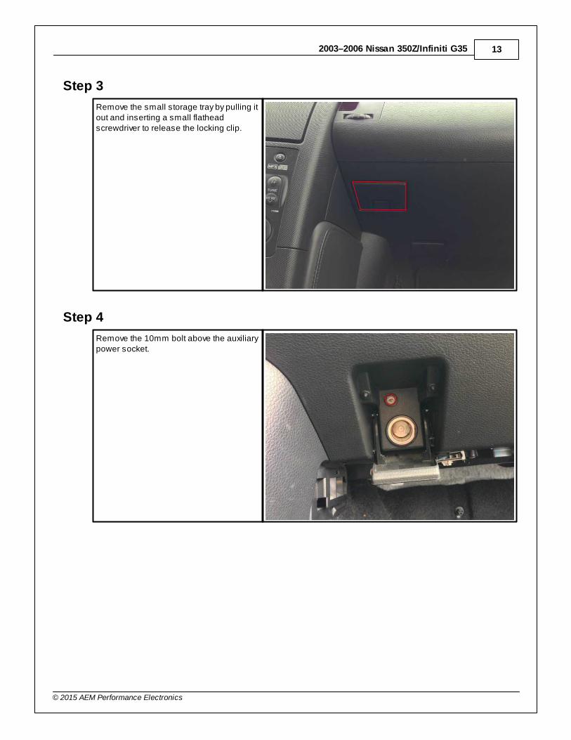
Step 3
Remove the small storage tray by pulling itout and inserting a small flatheadscrewdriver to release the locking clip.
Step 4
Remove the 10mm bolt above the auxiliarypower socket.
14
© 2015 AEM Performance Electronics
P/N 30-3520
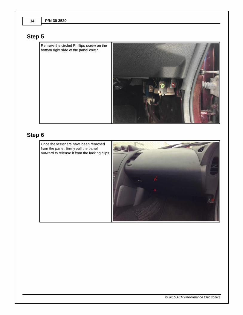
Step 5
Remove the circled Phillips screw on thebottom right side of the panel cover.
Step 6
Once the fasteners have been removedfrom the panel, firmly pull the paneloutward to release it from the locking clips.
2003–2006 Nissan 350Z/Infiniti G35 15
© 2015 AEM Performance Electronics
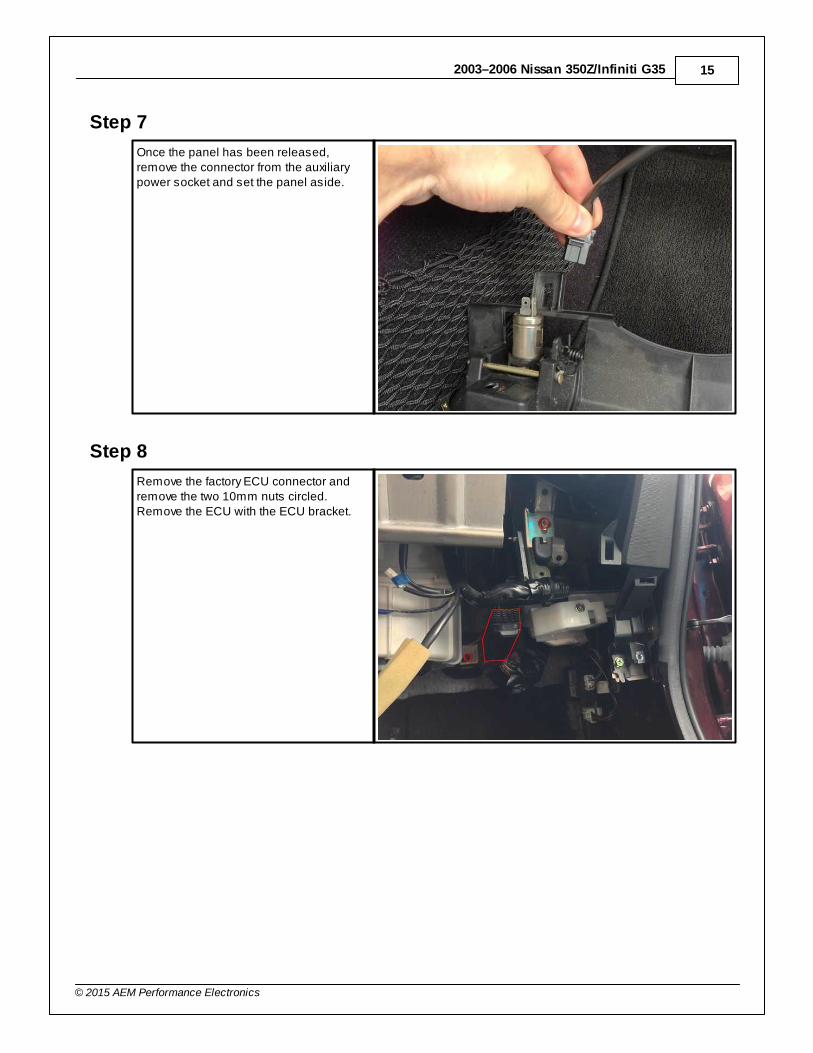
Step 7
Once the panel has been released,remove the connector from the auxiliarypower socket and set the panel aside.
Step 8
Remove the factory ECU connector andremove the two 10mm nuts circled.Remove the ECU with the ECU bracket.
16
© 2015 AEM Performance Electronics
P/N 30-3520
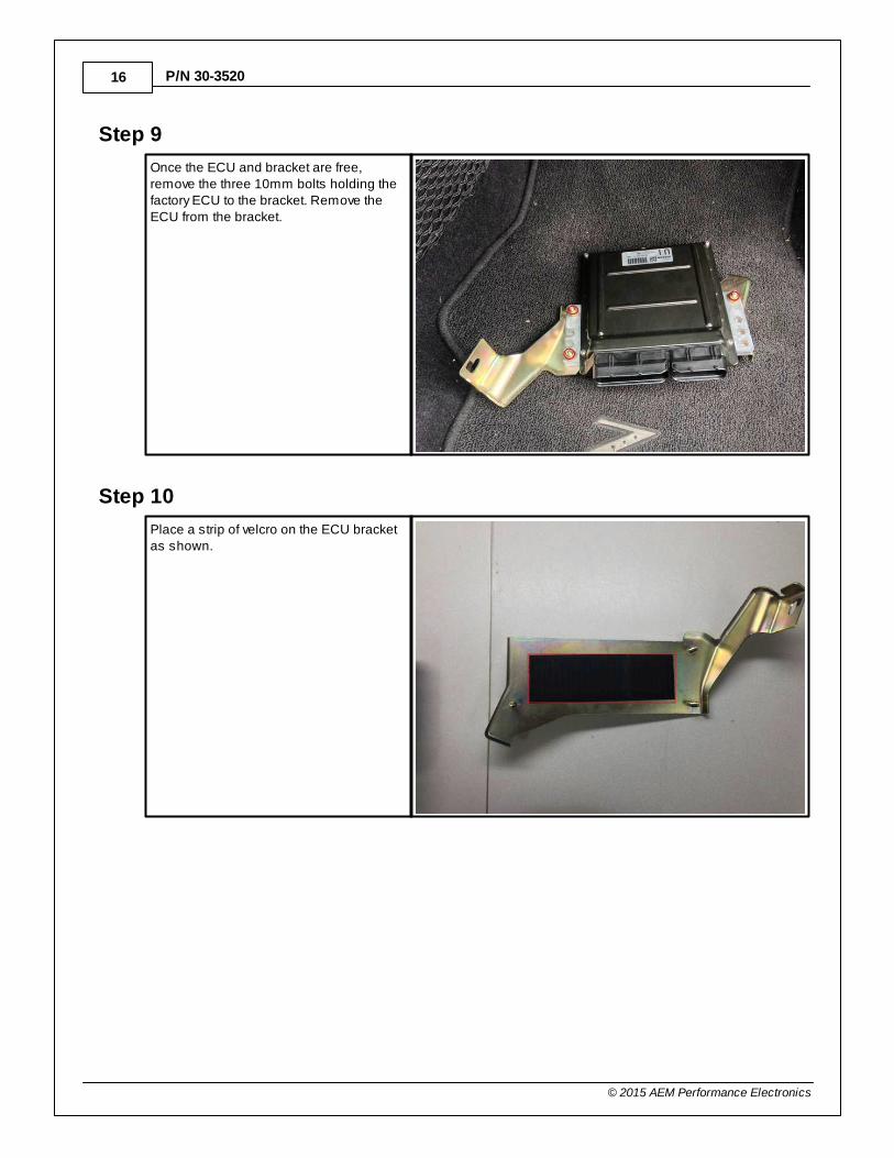
Step 9
Once the ECU and bracket are free,remove the three 10mm bolts holding thefactory ECU to the bracket. Remove theECU from the bracket.
Step 10
Place a strip of velcro on the ECU bracketas shown.
2003–2006 Nissan 350Z/Infiniti G35 17
© 2015 AEM Performance Electronics
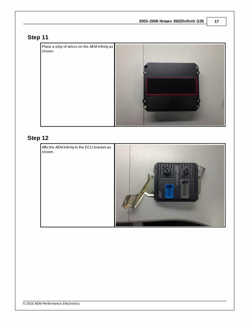
Step 11
Place a strip of velcro on the AEM Infinity asshown.
Step 12
Affix the AEM Infinity to the ECU bracket asshown.
18
© 2015 AEM Performance Electronics
P/N 30-3520
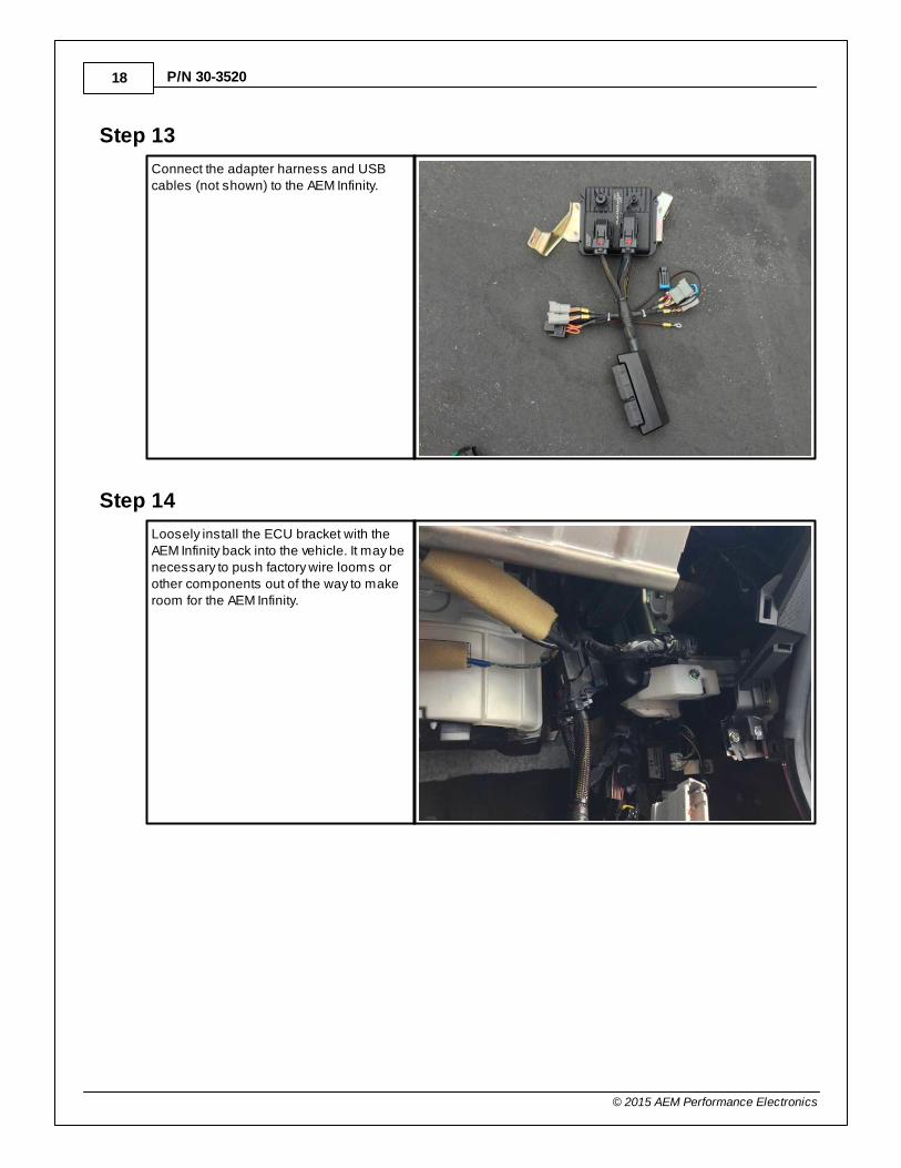
Step 13
Connect the adapter harness and USBcables (not shown) to the AEM Infinity.
Step 14
Loosely install the ECU bracket with theAEM Infinity back into the vehicle. It may benecessary to push factory wire looms orother components out of the way to makeroom for the AEM Infinity.
2003–2006 Nissan 350Z/Infiniti G35 19
© 2015 AEM Performance Electronics
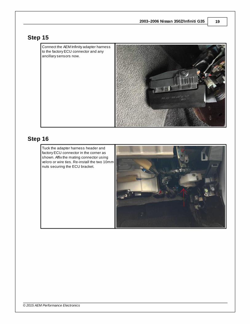
Step 15
Connect the AEM Infinity adapter harnessto the factory ECU connector and anyancillary sensors now.
Step 16
Tuck the adapter harness header andfactory ECU connector in the corner asshown. Affix the mating connector usingvelcro or wire ties. Re-install the two 10mmnuts securing the ECU bracket.
20
© 2015 AEM Performance Electronics
P/N 30-3520
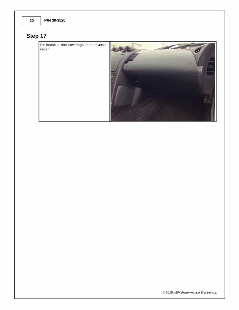
Step 17
Re-install all trim coverings in the reverseorder.
2003–2006 Nissan 350Z/Infiniti G35 21
© 2015 AEM Performance Electronics
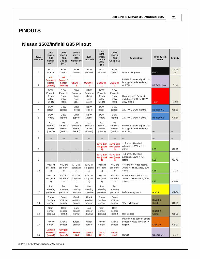
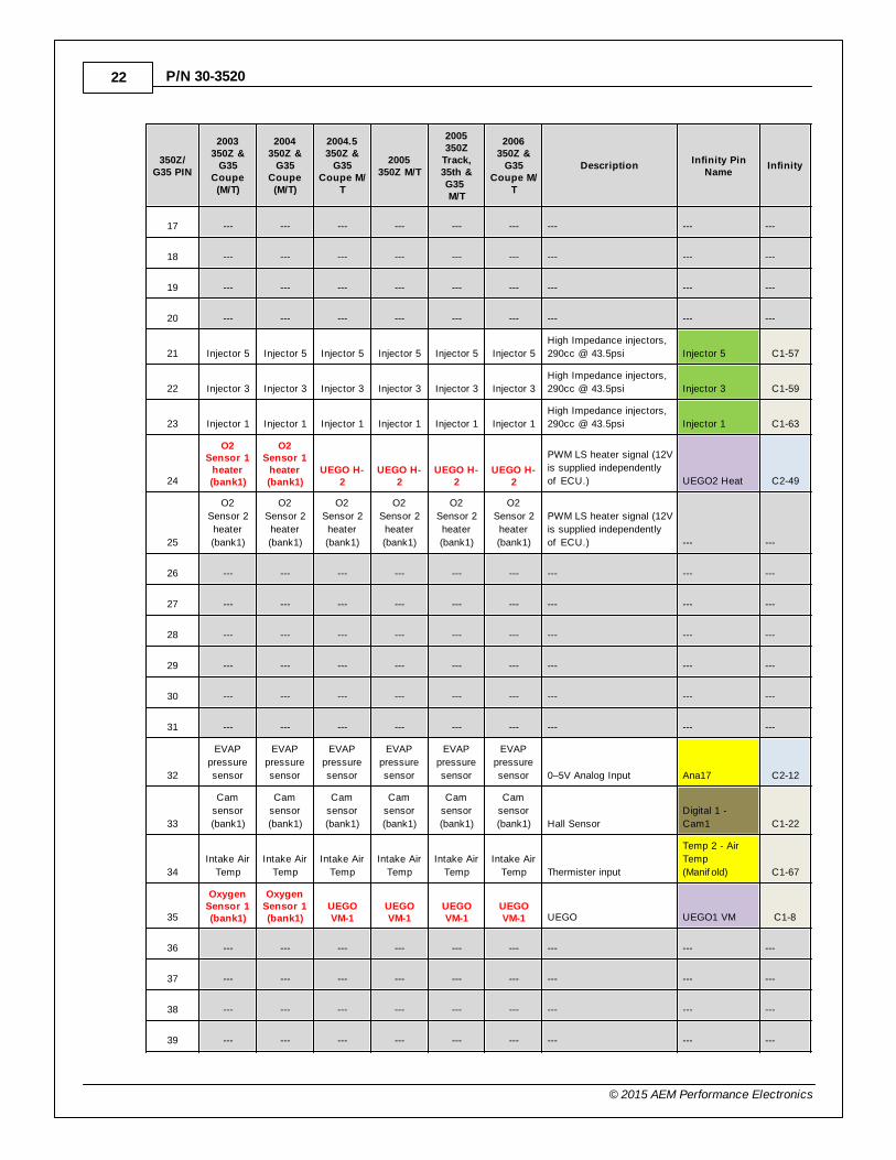
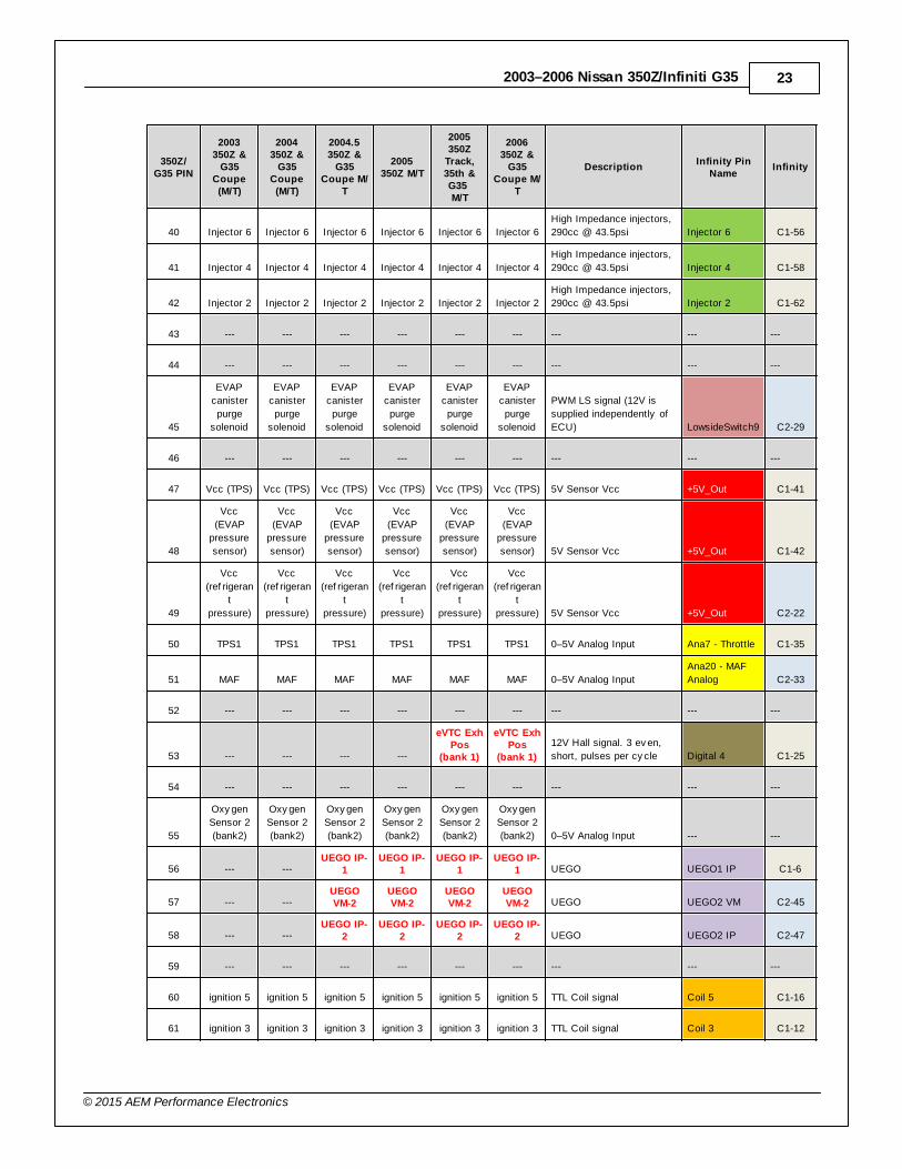
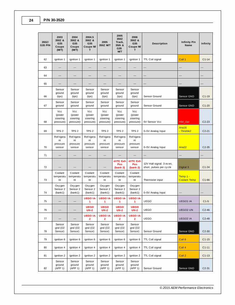
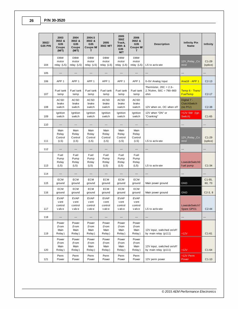
PINOUTS
Nissan 350Z/Infiniti G35 Pinout
350Z/G35 PIN
2003350Z &
G35Coupe(M/T)
2004350Z &
G35Coupe(M/T)
2004.5350Z &
G35Coupe M/
T
2005350Z M/T
2005350Z
Track,35th &G35 M/T
2006350Z &
G35Coupe M/
T
DescriptionInfinity Pin
NameInfinity
1
ECM
Ground
ECM
Ground
ECM
Ground
ECM
Ground
ECM
Ground
ECM
Ground Main power ground GND
C2-39,
40
2
O2Sensor 1
heater(bank2)
O2Sensor 1
heater(bank2)
UEGO H-1
UEGO H-1
UEGO H-1
UEGO H-1
PWM LS heater signal (12V
is supplied independently
of ECU.) UEGO1 Heat C1-4
3
DBW
Power In
(f rom
relay
p104)
DBW
Power In
(f rom
relay
p104)
DBW
Power In
(f rom
relay
p104)
DBW
Power In
(f rom
relay
p104)
DBW
Power In
(f rom
relay
p104)
DBW
Power In
(f rom
relay
p104)
High current 12V input,
switched on/of f by DBW
relay (p104) +12V C2-9
4
DBW
(close)
DBW
(close)
DBW
(close)
DBW
(close)
DBW
(close)
DBW
(close) 12V PWM DBW Control HBridge0_0 C1-53
5
DBW
(open)
DBW
(open)
DBW
(open)
DBW
(open)
DBW
(open)
DBW
(open) 12V PWM DBW Control HBridge0_1 C1-54
6
O2
Sensor 2
heater
(bank2)
O2
Sensor 2
heater
(bank2)
O2
Sensor 2
heater
(bank2)
O2
Sensor 2
heater
(bank2)
O2
Sensor 2
heater
(bank2)
O2
Sensor 2
heater
(bank2)
PWM LS heater signal (12V
is supplied independently
of ECU.) --- ---
7 --- --- --- --- --- --- --- --- ---
8 --- --- --- ---
eVTC ExhRet (bank
2)
eVTC ExhRet (bank
2)
~10 ohm, 0% = f ull
adv ance, 100% = f ull
retard LS9 C2-29
9 --- --- --- ---
eVTC ExhRet (bank
1)
eVTC ExhRet (bank
1)
~10 ohm, 0% = f ull
adv ance, 100% = f ull
retard LS8 C2-43
10
iVTC int
sol (bank
2)
iVTC int
sol (bank
2)
iVTC int
sol (bank
2)
iVTC int
sol (bank
2)
iVTC int
sol (bank
2)
iVTC int
sol (bank
2)
~7 ohm, 0% = f ull retard,
100% = f ull adv ance, 50%
= hold LS5 C1-2
11
iVTC int
sol (bank
1)
iVTC int
sol (bank
1)
iVTC int
sol (bank
1)
iVTC int
sol (bank
1)
iVTC int
sol (bank
1)
iVTC int
sol (bank
1)
~7 ohm, 0% = f ull retard,
100% = f ull adv ance, 50%
= hold LS3 C1-18
12
Pwr
steering
pressure
Pwr
steering
pressure
Pwr
steering
pressure
Pwr
steering
pressure
Pwr
steering
pressure
Pwr
steering
pressure 0–5V Analog Input Ana23 C2-36
13
Crank
position
sensor
Crank
position
sensor
Crank
position
sensor
Crank
position
sensor
Crank
position
sensor
Crank
position
sensor 12V Hall Sensor
Digital 0 -
Crank C1-21
14
Cam
sensor
(bank2)
Cam
sensor
(bank2)
Cam
sensor
(bank2)
Cam
sensor
(bank2)
Cam
sensor
(bank2)
Cam
sensor
(bank2) Hall Sensor
Digital 2 -
Cam2 C1-23
15
Knock
sensor
Knock
sensor
Knock
sensor
Knock
sensor
Knock
sensor
Knock
sensor
Piezoelectric sensor, single
sensor located in v alley of
engine. Knock 0 C1-27
16
Oxygensensor 1(bank2)
Oxygensensor 1(bank2)
UEGOUN-1
UEGOUN-1
UEGOUN-1
UEGOUN-1 UEGO UEGO1 UN C1-7
22
© 2015 AEM Performance Electronics
P/N 30-3520
350Z/G35 PIN
2003350Z &
G35Coupe(M/T)
2004350Z &
G35Coupe(M/T)
2004.5350Z &
G35Coupe M/
T
2005350Z M/T
2005350Z
Track,35th &G35 M/T
2006350Z &
G35Coupe M/
T
DescriptionInfinity Pin
NameInfinity
17 --- --- --- --- --- --- --- --- ---
18 --- --- --- --- --- --- --- --- ---
19 --- --- --- --- --- --- --- --- ---
20 --- --- --- --- --- --- --- --- ---
21 Injector 5 Injector 5 Injector 5 Injector 5 Injector 5 Injector 5
High Impedance injectors,
290cc @ 43.5psi Injector 5 C1-57
22 Injector 3 Injector 3 Injector 3 Injector 3 Injector 3 Injector 3
High Impedance injectors,
290cc @ 43.5psi Injector 3 C1-59
23 Injector 1 Injector 1 Injector 1 Injector 1 Injector 1 Injector 1
High Impedance injectors,
290cc @ 43.5psi Injector 1 C1-63
24
O2Sensor 1
heater(bank1)
O2Sensor 1
heater(bank1)
UEGO H-2
UEGO H-2
UEGO H-2
UEGO H-2
PWM LS heater signal (12V
is supplied independently
of ECU.) UEGO2 Heat C2-49
25
O2
Sensor 2
heater
(bank1)
O2
Sensor 2
heater
(bank1)
O2
Sensor 2
heater
(bank1)
O2
Sensor 2
heater
(bank1)
O2
Sensor 2
heater
(bank1)
O2
Sensor 2
heater
(bank1)
PWM LS heater signal (12V
is supplied independently
of ECU.) --- ---
26 --- --- --- --- --- --- --- --- ---
27 --- --- --- --- --- --- --- --- ---
28 --- --- --- --- --- --- --- --- ---
29 --- --- --- --- --- --- --- --- ---
30 --- --- --- --- --- --- --- --- ---
31 --- --- --- --- --- --- --- --- ---
32
EVAP
pressure
sensor
EVAP
pressure
sensor
EVAP
pressure
sensor
EVAP
pressure
sensor
EVAP
pressure
sensor
EVAP
pressure
sensor 0–5V Analog Input Ana17 C2-12
33
Cam
sensor
(bank1)
Cam
sensor
(bank1)
Cam
sensor
(bank1)
Cam
sensor
(bank1)
Cam
sensor
(bank1)
Cam
sensor
(bank1) Hall Sensor
Digital 1 -
Cam1 C1-22
34
Intake Air
Temp
Intake Air
Temp
Intake Air
Temp
Intake Air
Temp
Intake Air
Temp
Intake Air
Temp Thermister input
Temp 2 - Air
Temp
(Manif old) C1-67
35
OxygenSensor 1(bank1)
OxygenSensor 1(bank1)
UEGOVM-1
UEGOVM-1
UEGOVM-1
UEGOVM-1 UEGO UEGO1 VM C1-8
36 --- --- --- --- --- --- --- --- ---
37 --- --- --- --- --- --- --- --- ---
38 --- --- --- --- --- --- --- --- ---
39 --- --- --- --- --- --- --- --- ---
2003–2006 Nissan 350Z/Infiniti G35 23
© 2015 AEM Performance Electronics
350Z/G35 PIN
2003350Z &
G35Coupe(M/T)
2004350Z &
G35Coupe(M/T)
2004.5350Z &
G35Coupe M/
T
2005350Z M/T
2005350Z
Track,35th &G35 M/T
2006350Z &
G35Coupe M/
T
DescriptionInfinity Pin
NameInfinity
40 Injector 6 Injector 6 Injector 6 Injector 6 Injector 6 Injector 6
High Impedance injectors,
290cc @ 43.5psi Injector 6 C1-56
41 Injector 4 Injector 4 Injector 4 Injector 4 Injector 4 Injector 4
High Impedance injectors,
290cc @ 43.5psi Injector 4 C1-58
42 Injector 2 Injector 2 Injector 2 Injector 2 Injector 2 Injector 2
High Impedance injectors,
290cc @ 43.5psi Injector 2 C1-62
43 --- --- --- --- --- --- --- --- ---
44 --- --- --- --- --- --- --- --- ---
45
EVAP
canister
purge
solenoid
EVAP
canister
purge
solenoid
EVAP
canister
purge
solenoid
EVAP
canister
purge
solenoid
EVAP
canister
purge
solenoid
EVAP
canister
purge
solenoid
PWM LS signal (12V is
supplied independently of
ECU) LowsideSwitch9 C2-29
46 --- --- --- --- --- --- --- --- ---
47 Vcc (TPS) Vcc (TPS) Vcc (TPS) Vcc (TPS) Vcc (TPS) Vcc (TPS) 5V Sensor Vcc +5V_Out C1-41
48
Vcc
(EVAP
pressure
sensor)
Vcc
(EVAP
pressure
sensor)
Vcc
(EVAP
pressure
sensor)
Vcc
(EVAP
pressure
sensor)
Vcc
(EVAP
pressure
sensor)
Vcc
(EVAP
pressure
sensor) 5V Sensor Vcc +5V_Out C1-42
49
Vcc
(ref rigeran
t
pressure)
Vcc
(ref rigeran
t
pressure)
Vcc
(ref rigeran
t
pressure)
Vcc
(ref rigeran
t
pressure)
Vcc
(ref rigeran
t
pressure)
Vcc
(ref rigeran
t
pressure) 5V Sensor Vcc +5V_Out C2-22
50 TPS1 TPS1 TPS1 TPS1 TPS1 TPS1 0–5V Analog Input Ana7 - Throttle C1-35
51 MAF MAF MAF MAF MAF MAF 0–5V Analog Input
Ana20 - MAF
Analog C2-33
52 --- --- --- --- --- --- --- --- ---
53 --- --- --- ---
eVTC ExhPos
(bank 1)
eVTC ExhPos
(bank 1)
12V Hall signal. 3 ev en,
short, pulses per cy cle Digital 4 C1-25
54 --- --- --- --- --- --- --- --- ---
55
Oxy gen
Sensor 2
(bank2)
Oxy gen
Sensor 2
(bank2)
Oxy gen
Sensor 2
(bank2)
Oxy gen
Sensor 2
(bank2)
Oxy gen
Sensor 2
(bank2)
Oxy gen
Sensor 2
(bank2) 0–5V Analog Input --- ---
56 --- ---UEGO IP-
1UEGO IP-
1UEGO IP-
1UEGO IP-
1 UEGO UEGO1 IP C1-6
57 --- ---UEGOVM-2
UEGOVM-2
UEGOVM-2
UEGOVM-2 UEGO UEGO2 VM C2-45
58 --- ---UEGO IP-
2UEGO IP-
2UEGO IP-
2UEGO IP-
2 UEGO UEGO2 IP C2-47
59 --- --- --- --- --- --- --- --- ---
60 ignition 5 ignition 5 ignition 5 ignition 5 ignition 5 ignition 5 TTL Coil signal Coil 5 C1-16
61 ignition 3 ignition 3 ignition 3 ignition 3 ignition 3 ignition 3 TTL Coil signal Coil 3 C1-12
24
© 2015 AEM Performance Electronics
P/N 30-3520
350Z/G35 PIN
2003350Z &
G35Coupe(M/T)
2004350Z &
G35Coupe(M/T)
2004.5350Z &
G35Coupe M/
T
2005350Z M/T
2005350Z
Track,35th &G35 M/T
2006350Z &
G35Coupe M/
T
DescriptionInfinity Pin
NameInfinity
62 ignition 1 ignition 1 ignition 1 ignition 1 ignition 1 ignition 1 TTL Coil signal Coil 1 C1-14
63 --- --- --- --- --- --- --- --- ---
64 --- --- --- --- --- --- --- --- ---
65 --- --- --- --- --- --- --- --- ---
66
Sensor
ground
(tps)
Sensor
ground
(tps)
Sensor
ground
(tps)
Sensor
ground
(tps)
Sensor
ground
(tps)
Sensor
ground
(tps) Sensor Ground Sensor GND C1-19
67
Sensor
ground
Sensor
ground
Sensor
ground
Sensor
ground
Sensor
ground
Sensor
ground Sensor Ground Sensor GND C1-20
68
Vcc
(power
steering
pressure)
Vcc
(power
steering
pressure)
Vcc
(power
steering
pressure)
Vcc
(power
steering
pressure)
Vcc
(power
steering
pressure)
Vcc
(power
steering
pressure) 5V Sensor Vcc +5V_Out C2-23
69 TPS 2 TPS 2 TPS 2 TPS 2 TPS 2 TPS 2 0–5V Analog Input
Ana16
- Throttle2 C2-21
70
Ref rigera
nt
pressure
sensor
Ref rigera
nt
pressure
sensor
Ref rigera
nt
pressure
sensor
Ref rigera
nt
pressure
sensor
Ref rigera
nt
pressure
sensor
Ref rigera
nt
pressure
sensor 0–5V Analog Input Ana22 C2-35
71 --- --- --- --- --- --- --- --- ---
72 --- --- --- ---
eVTC ExhPos
(bank 2)
eVTC ExhPos
(bank 2)
12V Hall signal. 3 ev en,
short, pulses per cy cle Digital 3 C1-24
73
Coolant
temperatu
re
Coolant
temperatu
re
Coolant
temperatu
re
Coolant
temperatu
re
Coolant
temperatu
re
Coolant
temperatu
re Thermister input
Temp 1 -
Coolant Temp C1-66
74
Oxy gen
Sensor 2
(bank1)
Oxy gen
Sensor 2
(bank1)
Oxy gen
Sensor 2
(bank1)
Oxy gen
Sensor 2
(bank1)
Oxy gen
Sensor 2
(bank1)
Oxy gen
Sensor 2
(bank1) 0–5V Analog Input --- ---
75 --- ---UEGO IA-
1UEGO IA-
1UEGO IA-
1UEGO IA-
1 UEGO UEGO1 IA C1-5
76 --- ---UEGOUN-2
UEGOUN-2
UEGOUN-2
UEGOUN-2 UEGO UEGO2 UN C2-46
77 --- ---UEGO IA-
2UEGO IA-
2UEGO IA-
2UEGO IA-
2 UEGO UEGO2 IA C2-48
78
Sensor
gnd (O2
Sensor)
Sensor
gnd (O2
Sensor)
Sensor
gnd (O2
Sensor)
Sensor
gnd (O2
Sensor)
Sensor
gnd (O2
Sensor)
Sensor
gnd (O2
Sensor) Sensor Ground Sensor GND C2-30
79 ignition 6 ignition 6 ignition 6 ignition 6 ignition 6 ignition 6 TTL Coil signal Coil 6 C1-15
80 ignition 4 ignition 4 ignition 4 ignition 4 ignition 4 ignition 4 TTL Coil signal Coil 4 C1-11
81 ignition 2 ignition 2 ignition 2 ignition 2 ignition 2 ignition 2 TTL Coil signal Coil 2 C1-13
82
Sensor
ground
(APP 1)
Sensor
ground
(APP 1)
Sensor
ground
(APP 1)
Sensor
ground
(APP 1)
Sensor
ground
(APP 1)
Sensor
ground
(APP 1) Sensor Ground Sensor GND C2-31

2003–2006 Nissan 350Z/Infiniti G35 25
© 2015 AEM Performance Electronics
350Z/G35 PIN
2003350Z &
G35Coupe(M/T)
2004350Z &
G35Coupe(M/T)
2004.5350Z &
G35Coupe M/
T
2005350Z M/T
2005350Z
Track,35th &G35 M/T
2006350Z &
G35Coupe M/
T
DescriptionInfinity Pin
NameInfinity
83
Sensor
ground
(APP 2)
Sensor
ground
(APP 2)
Sensor
ground
(APP 2)
Sensor
ground
(APP 2)
Sensor
ground
(APP 2)
Sensor
ground
(APP 2) Sensor Ground Sensor GND C2-32
84 --- --- --- --- --- --- --- --- ---
85
DATA
Link
Connector
DATA
Link
Connector
Data link
Connector
Data link
Connector
Data link
Connector
Data link
Connector
ISO/KWP (Pin 7 on OBD 2
Connector) --- ---
86
CAN L
(w/120
ohm
resistor)
CAN L
(w/120
ohm
resistor)
CAN L
(w/120
ohm
resistor)
CAN L
(w/120
ohm
resistor)
CAN L
(w/120
ohm
resistor)
CAN L
(w/120
ohm
resistor) Terminated CAN node CAN B - C2-42
87 --- --- --- --- --- --- --- --- ---
88 --- --- --- --- --- --- --- --- ---
89 --- --- --- --- --- --- --- --- ---
90
Vcc (APP
1)
Vcc (APP
1)
Vcc (APP
1)
Vcc (APP
1)
Vcc (APP
1)
Vcc (APP
1) 5V Sensor Vcc +5V_Out C2-24
91
Vcc (APP
2)
Vcc (APP
2)
Vcc (APP
2)
Vcc (APP
2)
Vcc (APP
2)
Vcc (APP
2) 5V Sensor Vcc +5V_Out C2-24
92 --- --- --- --- --- --- --- --- ---
93 --- --- --- --- --- --- --- --- ---
94
CAN H
(w/120
ohm
resistor)
CAN H
(w/120
ohm
resistor)
CAN H
(w/120
ohm
resistor)
CAN H
(w/120
ohm
resistor)
CAN H
(w/120
ohm
resistor)
CAN H
(w/120
ohm
resistor) Terminated CAN node CAN B + C2-41
95 --- --- --- --- --- --- --- --- ---
96 --- --- --- --- --- --- --- --- ---
97 --- --- --- --- --- --- --- --- ---
98 APP 2 APP 2 APP 2 APP 2 APP 2 APP 2 0–5V Analog Input Ana19 - APP 2 C2-14
99
ASCD
steering
switch
ASCD
steering
switch
ASCD
steering
switch
ASCD
steering
switch
ASCD
steering
switch
ASCD
steering
switch
Use 2.49k Thermister
input. ~0v =Main,
~0.5v =Cancel, ~1v =set/
coast, ~1.9v =Res/Acc,
otherwise ~3.1v
Temp 4
- ChargeOutTe
mp C2-15
100 --- --- --- --- --- --- --- --- ---
101
stop lamp
switch
stop lamp
switch
stop lamp
switch
stop lamp
switch
stop lamp
switch
stop lamp
switch
0V released, 12V when
pressed
Digital 6 - (no
P/U) C2-37
102
PNP
switch
PNP
switch
PNP
switch
PNP
switch
PNP
switch
Neutral
Saf ety
Switch
Grounds when in Neutral,
otherwise O/C Digital 5 - C1-26
103 --- --- --- --- --- --- --- --- ---
26
© 2015 AEM Performance Electronics
P/N 30-3520
350Z/G35 PIN
2003350Z &
G35Coupe(M/T)
2004350Z &
G35Coupe(M/T)
2004.5350Z &
G35Coupe M/
T
2005350Z M/T
2005350Z
Track,35th &G35 M/T
2006350Z &
G35Coupe M/
T
DescriptionInfinity Pin
NameInfinity
104
DBW
motor
relay (LS)
DBW
motor
relay (LS)
DBW
motor
relay (LS)
DBW
motor
relay (LS)
DBW
motor
relay (LS)
DBW
motor
relay (LS) LS to activ ate
12V_Relay _Co
ntrol
C1-29
(splice)
105 --- --- --- --- --- --- --- --- ---
106 APP 1 APP 1 APP 1 APP 1 APP 1 APP 1 0–5V Analog Input Ana18 - APP 1 C2-13
107
Fuel tank
temp
Fuel tank
temp
Fuel tank
temp
Fuel tank
temp
Fuel tank
temp
Fuel tank
temp
Thermister, 20C = 2.3–
2.7Kohm, 50C = 790–900
ohm
Temp 6 - Trans/
FuelTemp C2-17
108
ACSD
brake
switch
ACSD
brake
switch
ACSD
brake
switch
ACSD
brake
switch
ACSD
brake
switch
ACSD
brake
switch 12V when on, OC when of f
Digital 7 -
ClutchSwitch
(no P/U) C2-38
109
Ignition
switch
Ignition
switch
Ignition
switch
Ignition
switch
Ignition
switch
Ignition
switch
12V when "ON" or
"Cranking"
+12V SW (Ign
Switch) C1-65
110 --- --- --- --- --- --- --- --- ---
111
Main
Relay
Control
(LS)
Main
Relay
Control
(LS)
Main
Relay
Control
(LS)
Main
Relay
Control
(LS)
Main
Relay
Control
(LS)
Main
Relay
Control
(LS) LS to activ ate
12V_Relay _Co
ntrol
C1-29
(splice)
112 --- --- --- --- --- --- --- --- ---
113
Fuel
Pump
Relay
(LS)
Fuel
Pump
Relay
(LS)
Fuel
Pump
Relay
(LS)
Fuel
Pump
Relay
(LS)
Fuel
Pump
Relay
(LS)
Fuel
Pump
Relay
(LS) LS to activ ate
LowsideSwitch0
f uel pump C1-34
114 --- --- --- --- --- --- --- --- ---
115
ECM
ground
ECM
ground
ECM
ground
ECM
ground
ECM
ground
ECM
ground Main power ground GND
C1-55,
60, 73
116
ECM
ground
ECM
ground
ECM
ground
ECM
ground
ECM
ground
ECM
ground Main power ground GND C2-3, 8
117
EVAP
v ent
control
v alv e
EVAP
v ent
control
v alv e
EVAP
v ent
control
v alv e
EVAP
v ent
control
v alv e
EVAP
v ent
control
v alv e
EVAP
v ent
control
v alv e LS to activ ate
LowsideSwitch7
Spare GPO1 C2-44
118 --- --- --- --- --- --- --- --- ---
119
Power
(f rom
Main
Relay )
Power
(f rom
Main
Relay )
Power
(f rom
Main
Relay )
Power
(f rom
Main
Relay )
Power
(f rom
Main
Relay )
Power
(f rom
Main
Relay )
12V input, switched on/of f
by main relay (p111) +12V C1-61
120
Power
(f rom
Main
Relay )
Power
(f rom
Main
Relay )
Power
(f rom
Main
Relay )
Power
(f rom
Main
Relay )
Power
(f rom
Main
Relay )
Power
(f rom
Main
Relay )
12V input, switched on/of f
by main relay (p111) +12V C1-64
121
Perm
Power
Perm
Power
Perm
Power
Perm
Power
Perm
Power
Perm
Power 12V perm power
+12V Perm
Power C1-10

2003–2006 Nissan 350Z/Infiniti G35 27
© 2015 AEM Performance Electronics
Infinity Pinouts
DedicatedDedicated and notreconfigurable
Assigned Assigned but reconfigurable
Available Available for user setup
Not Applicable Not used in this configuration
Required Required for proper function
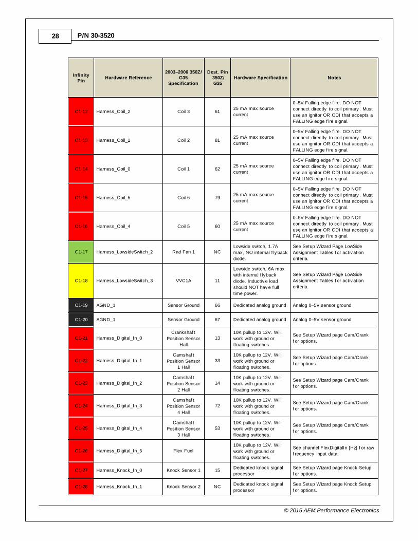
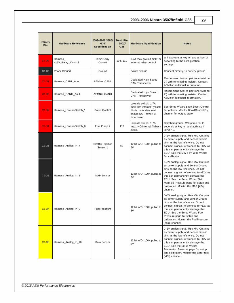
InfinityPin
Hardware Reference2003–2006 350Z/
G35Specification
Dest. Pin 350Z/G35
Hardware Specification Notes
C1-1 Harness_LowsideSwitch_4A/C Compressor
Clutch Relay
Lowside switch, 1.7A
max, NO internal f ly back
diode.
See Setup Wizard Page LowSide
Assignment Tables f or activ ation
criteria.
C1-2 Harness_LowsideSwitch_6VVC2A Solenoid
Control9
Lowside switch, 6A max
with internal f ly back
diode. Inductiv e load
should NOT hav e f ull
time power.
See Setup Wizard Page LowSide
Assignment Tables f or activ ation
criteria.
C1-3 Harness_LowsideSwitch_5VVC1B Solenoid
Control10
Lowside switch, 6A max
with internal f ly back
diode. Inductiv e load
should NOT hav e f ull
time power.
See Setup Wizard Page LowSide
Assignment Tables f or activ ation
criteria.
C1-4 Harness_UEGO_Heat-_1 UEGO 1 Heat 2
Bosch UEGO controller
Lowside switch f or UEGO heater
control. Connect to pin 4 of Bosch
UEGO sensor. NOTE that pin 3 of the
Sensor is heater (+) and must be
power by a f used/switched 12V
supply .
C1-5 Harness_UEGO_IA_1 UEGO 1 IA 75Trim Current signal. Connect to pin 2
of Bosch UEGO sensor.
C1-6 Harness_UEGO_IP_1 UEGO 1 IP 56Pumping Current signal. Connect to
pin 6 of Bosch UEGO sensor.
C1-7 Harness_UEGO_UN_1 UEGO 1 UN 16Nernst Voltage signal. Connect to pin
1 of Bosch UEGO sensor.
C1-8 Harness_UEGO_VM_1 UEGO 1 VM 35Virtual Ground signal. Connect to pin 5
of Bosch UEGO sensor.
C1-9 Harness_Flash_EnableHarness Flash
Enable 10K pulldown
Not usually needed f or automatic
f irmware updates through Inf inity
Tuner. If connection errors occur
during update, connect 12 v olts to this
pin bef ore proceeding with upgrade.
Disconnect the 12 v olts signal af ter
the update.
C1-10 +12V_R8C_CPUBattery Perm
Power121
Dedicated power
management CPU
Full time battery power. MUST be
powered bef ore the ignition switch
input is triggered (See C1-65).
C1-11 Harness_Coil_3 Coil 4 8025 mA max source
current
0–5V Falling edge f ire. DO NOT
connect directly to coil primary . Must
use an ignitor OR CDI that accepts a
FALLING edge f ire signal.
28
© 2015 AEM Performance Electronics
P/N 30-3520
InfinityPin
Hardware Reference2003–2006 350Z/
G35Specification
Dest. Pin 350Z/G35
Hardware Specification Notes
C1-12 Harness_Coil_2 Coil 3 6125 mA max source
current
0–5V Falling edge f ire. DO NOT
connect directly to coil primary . Must
use an ignitor OR CDI that accepts a
FALLING edge f ire signal.
C1-13 Harness_Coil_1 Coil 2 8125 mA max source
current
0–5V Falling edge f ire. DO NOT
connect directly to coil primary . Must
use an ignitor OR CDI that accepts a
FALLING edge f ire signal.
C1-14 Harness_Coil_0 Coil 1 6225 mA max source
current
0–5V Falling edge f ire. DO NOT
connect directly to coil primary . Must
use an ignitor OR CDI that accepts a
FALLING edge f ire signal.
C1-15 Harness_Coil_5 Coil 6 7925 mA max source
current
0–5V Falling edge f ire. DO NOT
connect directly to coil primary . Must
use an ignitor OR CDI that accepts a
FALLING edge f ire signal.
C1-16 Harness_Coil_4 Coil 5 6025 mA max source
current
0–5V Falling edge f ire. DO NOT
connect directly to coil primary . Must
use an ignitor OR CDI that accepts a
FALLING edge f ire signal.
C1-17 Harness_LowsideSwitch_2 Rad Fan 1 NCLowside switch, 1.7A
max, NO internal f ly back
diode.
See Setup Wizard Page LowSide
Assignment Tables f or activ ation
criteria.
C1-18 Harness_LowsideSwitch_3 VVC1A 11
Lowside switch, 6A max
with internal f ly back
diode. Inductiv e load
should NOT hav e f ull
time power.
See Setup Wizard Page LowSide
Assignment Tables f or activ ation
criteria.
C1-19 AGND_1 Sensor Ground 66 Dedicated analog ground Analog 0–5V sensor ground
C1-20 AGND_1 Sensor Ground 67 Dedicated analog ground Analog 0–5V sensor ground
C1-21 Harness_Digital_In_0Crankshaf t
Position Sensor
Hall
1310K pullup to 12V. Will
work with ground or
f loating switches.
See Setup Wizard page Cam/Crank
f or options.
C1-22 Harness_Digital_In_1Camshaf t
Position Sensor
1 Hall
3310K pullup to 12V. Will
work with ground or
f loating switches.
See Setup Wizard page Cam/Crank
f or options.
C1-23 Harness_Digital_In_2Camshaf t
Position Sensor
2 Hall
1410K pullup to 12V. Will
work with ground or
f loating switches.
See Setup Wizard page Cam/Crank
f or options.
C1-24 Harness_Digital_In_3Camshaf t
Position Sensor
4 Hall
7210K pullup to 12V. Will
work with ground or
f loating switches.
See Setup Wizard page Cam/Crank
f or options.
C1-25 Harness_Digital_In_4Camshaf t
Position Sensor
3 Hall
5310K pullup to 12V. Will
work with ground or
f loating switches.
See Setup Wizard page Cam/Crank
f or options.
C1-26 Harness_Digital_In_5 Flex Fuel 10K pullup to 12V. Will
work with ground or
f loating switches.
See channel FlexDigitalIn [Hz] f or raw
f requency input data.
C1-27 Harness_Knock_In_0 Knock Sensor 1 15Dedicated knock signal
processor
See Setup Wizard page Knock Setup
f or options.
C1-28 Harness_Knock_In_1 Knock Sensor 2 NCDedicated knock signal
processor
See Setup Wizard page Knock Setup
f or options.
2003–2006 Nissan 350Z/Infiniti G35 29
© 2015 AEM Performance Electronics
InfinityPin
Hardware Reference2003–2006 350Z/
G35Specification
Dest. Pin 350Z/G35
Hardware Specification Notes
C1-29Harness_
+12V_Relay _Control
+12V Relay
Control104, 111
0.7A max ground sink f or
external relay control
Will activ ate at key on and at key of f
according to the conf iguration
settings.
C1-30 Power Ground Ground Power Ground Connect directly to battery ground.
C1-31 Harness_CANL_Aout AEMNet CANL Dedicated High Speed
CAN Transceiv er
Recommend twisted pair (one twist per
2") with terminating resistor. Contact
AEM f or additional inf ormation.
C1-32 Harness_CANH_Aout AEMNet CANH Dedicated High Speed
CAN Transceiv er
Recommend twisted pair (one twist per
2") with terminating resistor. Contact
AEM f or additional inf ormation.
C1-33 Harness_LowsideSwitch_1 Boost Control
Lowside switch, 1.7A
max with internal f ly back
diode. Inductiv e load
should NOT hav e f ull
time power.
See Setup Wizard page Boost Control
f or options. Monitor BoostControl [%]
channel f or output state.
C1-34 Harness_LowsideSwitch_0 Fuel Pump 2 113Lowside switch, 1.7A
max, NO internal f ly back
diode.
Switched ground. Will prime f or 2
seconds at key on and activ ate if
RPM > 0.
C1-35 Harness_Analog_In_7Throttle Position
Sensor 150
12 bit A/D, 100K pullup to
5V
0–5V analog signal. Use +5V Out pins
as power supply and Sensor Ground
pins as the low ref erence. Do not
connect signals ref erenced to +12V as
this can permanently damage the
ECU. See the Driv e by Wire Wizard
f or calibration.
C1-36 Harness_Analog_In_8 MAP Sensor 12 bit A/D, 100K pullup to
5V
0–5V analog signal. Use +5V Out pins
as power supply and Sensor Ground
pins as the low ref erence. Do not
connect signals ref erenced to +12V as
this can permanently damage the
ECU. See the Setup Wizard Set
Manif old Pressure page f or setup and
calibration. Monitor the MAP [kPa]
channel.
C1-37 Harness_Analog_In_9 Fuel Pressure 12 bit A/D, 100K pullup to
5V
0–5V analog signal. Use +5V Out pins
as power supply and Sensor Ground
pins as the low ref erence. Do not
connect signals ref erenced to +12V as
this can permanently damage the
ECU. See the Setup Wizard Fuel
Pressure page f or setup and
calibration. Monitor the FuelPressure
[psig] channel.
C1-38 Harness_Analog_In_10 Baro Sensor 12 bit A/D, 100K pullup to
5V
0–5V analog signal. Use +5V Out pins
as power supply and Sensor Ground
pins as the low ref erence. Do not
connect signals ref erenced to +12V as
this can permanently damage the
ECU. See the Setup Wizard
Barometric Pressure page f or setup
and calibration. Monitor the BaroPress
[kPa] channel.
30
© 2015 AEM Performance Electronics
P/N 30-3520
InfinityPin
Hardware Reference2003–2006 350Z/
G35Specification
Dest. Pin 350Z/G35
Hardware Specification Notes
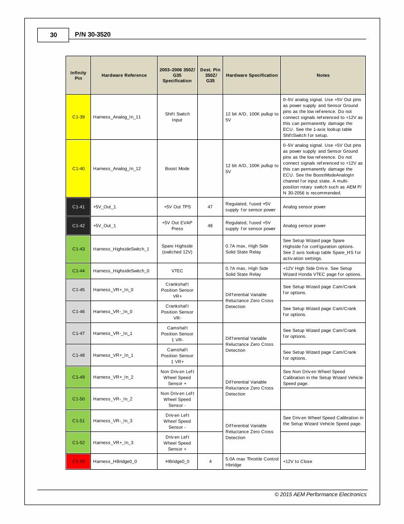
C1-39 Harness_Analog_In_11Shif t Switch
Input
12 bit A/D, 100K pullup to
5V
0–5V analog signal. Use +5V Out pins
as power supply and Sensor Ground
pins as the low ref erence. Do not
connect signals ref erenced to +12V as
this can permanently damage the
ECU. See the 1-axis lookup table
Shif tSwitch f or setup.
C1-40 Harness_Analog_In_12 Boost Mode 12 bit A/D, 100K pullup to
5V
0–5V analog signal. Use +5V Out pins
as power supply and Sensor Ground
pins as the low ref erence. Do not
connect signals ref erenced to +12V as
this can permanently damage the
ECU. See the BoostModeAnalogIn
channel f or input state. A multi-
position rotary switch such as AEM P/
N 30-2056 is recommended.
C1-41 +5V_Out_1 +5V Out TPS 47Regulated, f used +5V
supply f or sensor powerAnalog sensor power
C1-42 +5V_Out_1+5V Out EVAP
Press48
Regulated, f used +5V
supply f or sensor powerAnalog sensor power
C1-43 Harness_HighsideSwitch_1Spare Highside
(switched 12V)
0.7A max, High Side
Solid State Relay
See Setup Wizard page Spare
Highside f or conf iguration options.
See 2 axis lookup table Spare_HS f or
activ ation settings.
C1-44 Harness_HighsideSwitch_0 VTEC 0.7A max, High Side
Solid State Relay
+12V High Side Driv e. See Setup
Wizard Honda VTEC page f or options.
C1-45 Harness_VR+_In_0Crankshaf t
Position Sensor
VR+
Dif f erential Variable
Reluctance Zero Cross
Detection
See Setup Wizard page Cam/Crank
f or options.
C1-46 Harness_VR-_In_0Crankshaf t
Position Sensor
VR-
See Setup Wizard page Cam/Crank
f or options.
C1-47 Harness_VR-_In_1Camshaf t
Position Sensor
1 VR-
Dif f erential Variable
Reluctance Zero Cross
Detection
See Setup Wizard page Cam/Crank
f or options.
C1-48 Harness_VR+_In_1Camshaf t
Position Sensor
1 VR+
See Setup Wizard page Cam/Crank
f or options.
C1-49 Harness_VR+_In_2Non Driv en Lef t
Wheel Speed
Sensor +
Dif f erential Variable
Reluctance Zero Cross
Detection
See Non Driv en Wheel Speed
Calibration in the Setup Wizard Vehicle
Speed page.
C1-50 Harness_VR-_In_2Non Driv en Lef t
Wheel Speed
Sensor -
C1-51 Harness_VR-_In_3Driv en Lef t
Wheel Speed
Sensor -
Dif f erential Variable
Reluctance Zero Cross
Detection
See Driv en Wheel Speed Calibration in
the Setup Wizard Vehicle Speed page.
C1-52 Harness_VR+_In_3Driv en Lef t
Wheel Speed
Sensor +
C1-53 Harness_HBridge0_0 HBridge0_0 45.0A max Throttle Control
Hbridge+12V to Close

2003–2006 Nissan 350Z/Infiniti G35 31
© 2015 AEM Performance Electronics
InfinityPin
Hardware Reference2003–2006 350Z/
G35Specification
Dest. Pin 350Z/G35
Hardware Specification Notes
C1-54 Harness_HBridge0_1 HBridge0_1 55.0A max Throttle Control
Hbridge+12V to Open
C1-55 Power Ground Ground 115 Power Ground Connect directly to battery ground.
C1-56 Harness_Injector_5 Injector 6 40Saturated or peak and
hold, 3A max continuousInjector 6
C1-57 Harness_Injector_4 Injector 5 21Saturated or peak and
hold, 3A max continuousInjector 5
C1-58 Harness_Injector_3 Injector 4 41Saturated or peak and
hold, 3A max continuousInjector 4
C1-59 Harness_Injector_2 Injector 3 22Saturated or peak and
hold, 3A max continuousInjector 3
C1-60 Power Ground Ground 115 Power Ground Connect directly to battery ground.
C1-61 +12V +12V In 119 12 v olt power f rom relay12 v olt power f rom relay . Relay must
be controlled by +12V Relay Control
signal, pin C1-29 abov e.
C1-62 Harness_Injector_1 Injector 2 42Saturated or peak and
hold, 3A max continuousInjector 2
C1-63 Harness_Injector_0 Injector 1 23Saturated or peak and
hold, 3A max continuousInjector 1
C1-64 +12V +12V In 120 12 v olt power f rom relay12 v olt power f rom relay . Relay must
be controlled by +12V Relay Control
signal pin C1-29 abov e.
C1-65 Harness_+12V_SW Ignition Switch 109 10K pulldownFull time battery power must be
av ailable at C1-10 bef ore this input is
triggered.
C1-66 Harness_Analog_In_Temp_1Coolant Temp
Sensor73
12 bit A/D, 2.49K pullup
to 5V
See CoolantTempCal [C] table f or
calibration data and CoolantTemp [C]
f or channel data.
C1-67 Harness_Analog_In_Temp_2Intake Air
Temperature34
12 bit A/D, 2.49K pullup
to 5V
See AirTempCal [C] table f or
calibration data and AirTemp [C] f or
channel data.
C1-68 Harness_Analog_In_Temp_3Oil Temperature
Sensor
12 bit A/D, 2.49K pullup
to 5V
See OilTempCal table f or calibration
data and OilTemp [C] f or channel
data.
C1-69 Harness_Stepper_2A Stepper 2A
Programmable Stepper
Driv er, up to 28V and
±1.4A
Be sure that each internal coil of the
stepper motor is properly paired with
the 1A/1B and 2A/2B ECU outputs.
Supports Bi-Polar stepper motors only .
C1-70 Harness_Stepper_1A Stepper 1A
Programmable Stepper
Driv er, up to 28V and
±1.4A
Be sure that each internal coil of the
stepper motor is properly paired with
the 1A/1B and 2A/2B ECU outputs.
Supports Bi-Polar stepper motors only .
C1-71 Harness_Stepper_2B Stepper 2B
Programmable Stepper
Driv er, up to 28V and
±1.4A
Be sure that each internal coil of the
stepper motor is properly paired with
the 1A/1B and 2A/2B ECU outputs.
Supports Bi-Polar stepper motors only .
32
© 2015 AEM Performance Electronics
P/N 30-3520
InfinityPin
Hardware Reference2003–2006 350Z/
G35Specification
Dest. Pin 350Z/G35
Hardware Specification Notes
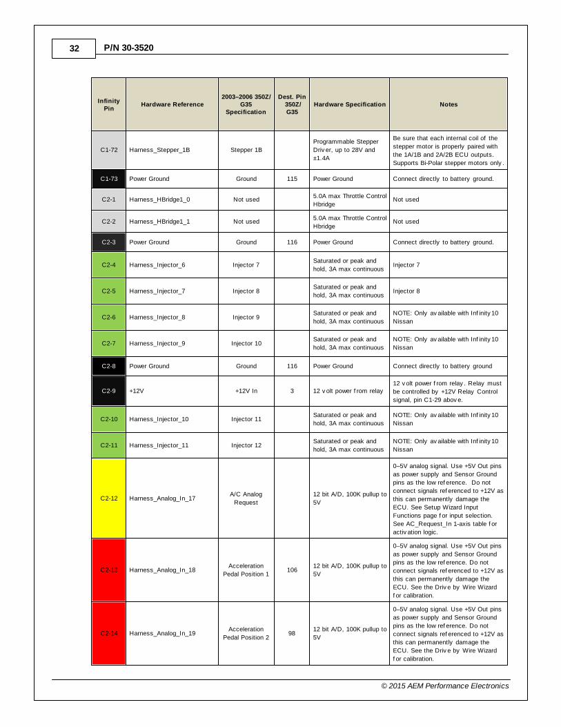
C1-72 Harness_Stepper_1B Stepper 1B
Programmable Stepper
Driv er, up to 28V and
±1.4A
Be sure that each internal coil of the
stepper motor is properly paired with
the 1A/1B and 2A/2B ECU outputs.
Supports Bi-Polar stepper motors only .
C1-73 Power Ground Ground 115 Power Ground Connect directly to battery ground.
C2-1 Harness_HBridge1_0 Not used 5.0A max Throttle Control
HbridgeNot used
C2-2 Harness_HBridge1_1 Not used 5.0A max Throttle Control
HbridgeNot used
C2-3 Power Ground Ground 116 Power Ground Connect directly to battery ground.
C2-4 Harness_Injector_6 Injector 7 Saturated or peak and
hold, 3A max continuousInjector 7
C2-5 Harness_Injector_7 Injector 8 Saturated or peak and
hold, 3A max continuousInjector 8
C2-6 Harness_Injector_8 Injector 9 Saturated or peak and
hold, 3A max continuous
NOTE: Only av ailable with Inf inity 10
Nissan
C2-7 Harness_Injector_9 Injector 10 Saturated or peak and
hold, 3A max continuous
NOTE: Only av ailable with Inf inity 10
Nissan
C2-8 Power Ground Ground 116 Power Ground Connect directly to battery ground
C2-9 +12V +12V In 3 12 v olt power f rom relay12 v olt power f rom relay . Relay must
be controlled by +12V Relay Control
signal, pin C1-29 abov e.
C2-10 Harness_Injector_10 Injector 11 Saturated or peak and
hold, 3A max continuous
NOTE: Only av ailable with Inf inity 10
Nissan
C2-11 Harness_Injector_11 Injector 12 Saturated or peak and
hold, 3A max continuous
NOTE: Only av ailable with Inf inity 10
Nissan
C2-12 Harness_Analog_In_17A/C Analog
Request
12 bit A/D, 100K pullup to
5V
0–5V analog signal. Use +5V Out pins
as power supply and Sensor Ground
pins as the low ref erence. Do not
connect signals ref erenced to +12V as
this can permanently damage the
ECU. See Setup Wizard Input
Functions page f or input selection.
See AC_Request_In 1-axis table f or
activ ation logic.
C2-13 Harness_Analog_In_18Acceleration
Pedal Position 1106
12 bit A/D, 100K pullup to
5V
0–5V analog signal. Use +5V Out pins
as power supply and Sensor Ground
pins as the low ref erence. Do not
connect signals ref erenced to +12V as
this can permanently damage the
ECU. See the Driv e by Wire Wizard
f or calibration.
C2-14 Harness_Analog_In_19Acceleration
Pedal Position 298
12 bit A/D, 100K pullup to
5V
0–5V analog signal. Use +5V Out pins
as power supply and Sensor Ground
pins as the low ref erence. Do not
connect signals ref erenced to +12V as
this can permanently damage the
ECU. See the Driv e by Wire Wizard
f or calibration.
2003–2006 Nissan 350Z/Infiniti G35 33
© 2015 AEM Performance Electronics
InfinityPin
Hardware Reference2003–2006 350Z/
G35Specification
Dest. Pin 350Z/G35
Hardware Specification Notes
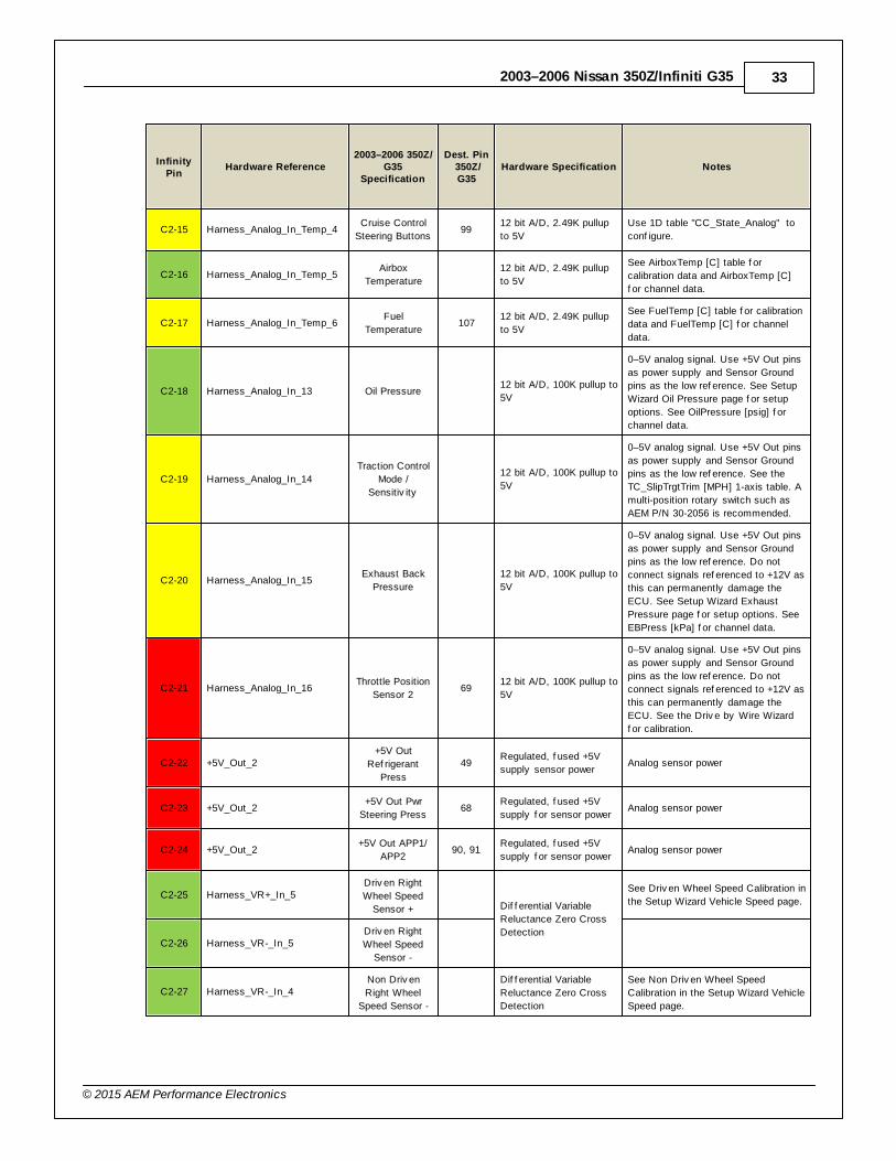
C2-15 Harness_Analog_In_Temp_4Cruise Control
Steering Buttons99
12 bit A/D, 2.49K pullup
to 5V
Use 1D table "CC_State_Analog" to
conf igure.
C2-16 Harness_Analog_In_Temp_5Airbox
Temperature
12 bit A/D, 2.49K pullup
to 5V
See AirboxTemp [C] table f or
calibration data and AirboxTemp [C]
f or channel data.
C2-17 Harness_Analog_In_Temp_6Fuel
Temperature107
12 bit A/D, 2.49K pullup
to 5V
See FuelTemp [C] table f or calibration
data and FuelTemp [C] f or channel
data.
C2-18 Harness_Analog_In_13 Oil Pressure 12 bit A/D, 100K pullup to
5V
0–5V analog signal. Use +5V Out pins
as power supply and Sensor Ground
pins as the low ref erence. See Setup
Wizard Oil Pressure page f or setup
options. See OilPressure [psig] f or
channel data.
C2-19 Harness_Analog_In_14
Traction Control
Mode /
Sensitiv ity
12 bit A/D, 100K pullup to
5V
0–5V analog signal. Use +5V Out pins
as power supply and Sensor Ground
pins as the low ref erence. See the
TC_SlipTrgtTrim [MPH] 1-axis table. A
multi-position rotary switch such as
AEM P/N 30-2056 is recommended.
C2-20 Harness_Analog_In_15Exhaust Back
Pressure
12 bit A/D, 100K pullup to
5V
0–5V analog signal. Use +5V Out pins
as power supply and Sensor Ground
pins as the low ref erence. Do not
connect signals ref erenced to +12V as
this can permanently damage the
ECU. See Setup Wizard Exhaust
Pressure page f or setup options. See
EBPress [kPa] f or channel data.
C2-21 Harness_Analog_In_16Throttle Position
Sensor 269
12 bit A/D, 100K pullup to
5V
0–5V analog signal. Use +5V Out pins
as power supply and Sensor Ground
pins as the low ref erence. Do not
connect signals ref erenced to +12V as
this can permanently damage the
ECU. See the Driv e by Wire Wizard
f or calibration.
C2-22 +5V_Out_2+5V Out
Ref rigerant
Press
49Regulated, f used +5V
supply sensor powerAnalog sensor power
C2-23 +5V_Out_2+5V Out Pwr
Steering Press68
Regulated, f used +5V
supply f or sensor powerAnalog sensor power
C2-24 +5V_Out_2+5V Out APP1/
APP290, 91
Regulated, f used +5V
supply f or sensor powerAnalog sensor power
C2-25 Harness_VR+_In_5Driv en Right
Wheel Speed
Sensor +
Dif f erential Variable
Reluctance Zero Cross
Detection
See Driv en Wheel Speed Calibration in
the Setup Wizard Vehicle Speed page.
C2-26 Harness_VR-_In_5Driv en Right
Wheel Speed
Sensor -
C2-27 Harness_VR-_In_4Non Driv en
Right Wheel
Speed Sensor -
Dif f erential Variable
Reluctance Zero Cross
Detection
See Non Driv en Wheel Speed
Calibration in the Setup Wizard Vehicle
Speed page.
34
© 2015 AEM Performance Electronics
P/N 30-3520
InfinityPin
Hardware Reference2003–2006 350Z/
G35Specification
Dest. Pin 350Z/G35
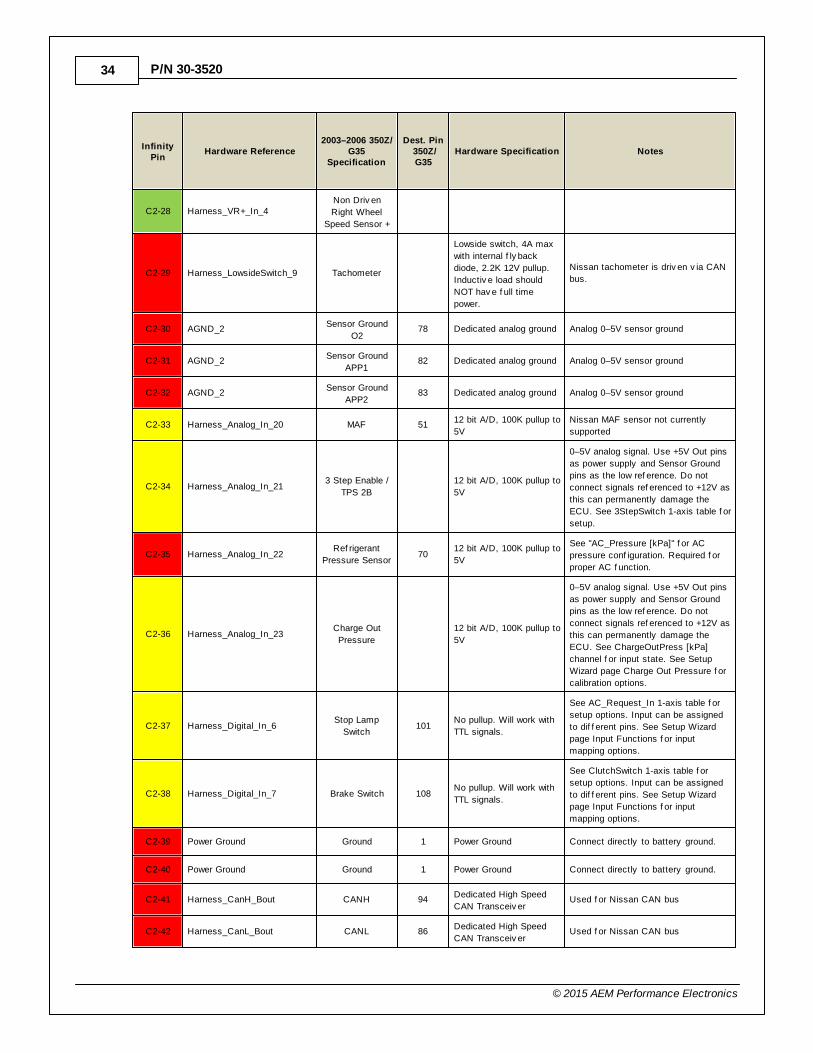
Hardware Specification Notes
C2-28 Harness_VR+_In_4Non Driv en
Right Wheel
Speed Sensor +
C2-29 Harness_LowsideSwitch_9 Tachometer
Lowside switch, 4A max
with internal f ly back
diode, 2.2K 12V pullup.
Inductiv e load should
NOT hav e f ull time
power.
Nissan tachometer is driv en v ia CAN
bus.
C2-30 AGND_2Sensor Ground
O278 Dedicated analog ground Analog 0–5V sensor ground
C2-31 AGND_2Sensor Ground
APP182 Dedicated analog ground Analog 0–5V sensor ground
C2-32 AGND_2Sensor Ground
APP283 Dedicated analog ground Analog 0–5V sensor ground
C2-33 Harness_Analog_In_20 MAF 5112 bit A/D, 100K pullup to
5V
Nissan MAF sensor not currently
supported
C2-34 Harness_Analog_In_213 Step Enable /
TPS 2B
12 bit A/D, 100K pullup to
5V
0–5V analog signal. Use +5V Out pins
as power supply and Sensor Ground
pins as the low ref erence. Do not
connect signals ref erenced to +12V as
this can permanently damage the
ECU. See 3StepSwitch 1-axis table f or
setup.
C2-35 Harness_Analog_In_22Ref rigerant
Pressure Sensor70
12 bit A/D, 100K pullup to
5V
See "AC_Pressure [kPa]" f or AC
pressure conf iguration. Required f or
proper AC f unction.
C2-36 Harness_Analog_In_23Charge Out
Pressure
12 bit A/D, 100K pullup to
5V
0–5V analog signal. Use +5V Out pins
as power supply and Sensor Ground
pins as the low ref erence. Do not
connect signals ref erenced to +12V as
this can permanently damage the
ECU. See ChargeOutPress [kPa]
channel f or input state. See Setup
Wizard page Charge Out Pressure f or
calibration options.
C2-37 Harness_Digital_In_6Stop Lamp
Switch101
No pullup. Will work with
TTL signals.
See AC_Request_In 1-axis table f or
setup options. Input can be assigned
to dif f erent pins. See Setup Wizard
page Input Functions f or input
mapping options.
C2-38 Harness_Digital_In_7 Brake Switch 108No pullup. Will work with
TTL signals.
See ClutchSwitch 1-axis table f or
setup options. Input can be assigned
to dif f erent pins. See Setup Wizard
page Input Functions f or input
mapping options.
C2-39 Power Ground Ground 1 Power Ground Connect directly to battery ground.
C2-40 Power Ground Ground 1 Power Ground Connect directly to battery ground.
C2-41 Harness_CanH_Bout CANH 94Dedicated High Speed
CAN Transceiv erUsed f or Nissan CAN bus
C2-42 Harness_CanL_Bout CANL 86Dedicated High Speed
CAN Transceiv erUsed f or Nissan CAN bus
2003–2006 Nissan 350Z/Infiniti G35 35
© 2015 AEM Performance Electronics
InfinityPin
Hardware Reference2003–2006 350Z/
G35Specification
Dest. Pin 350Z/G35
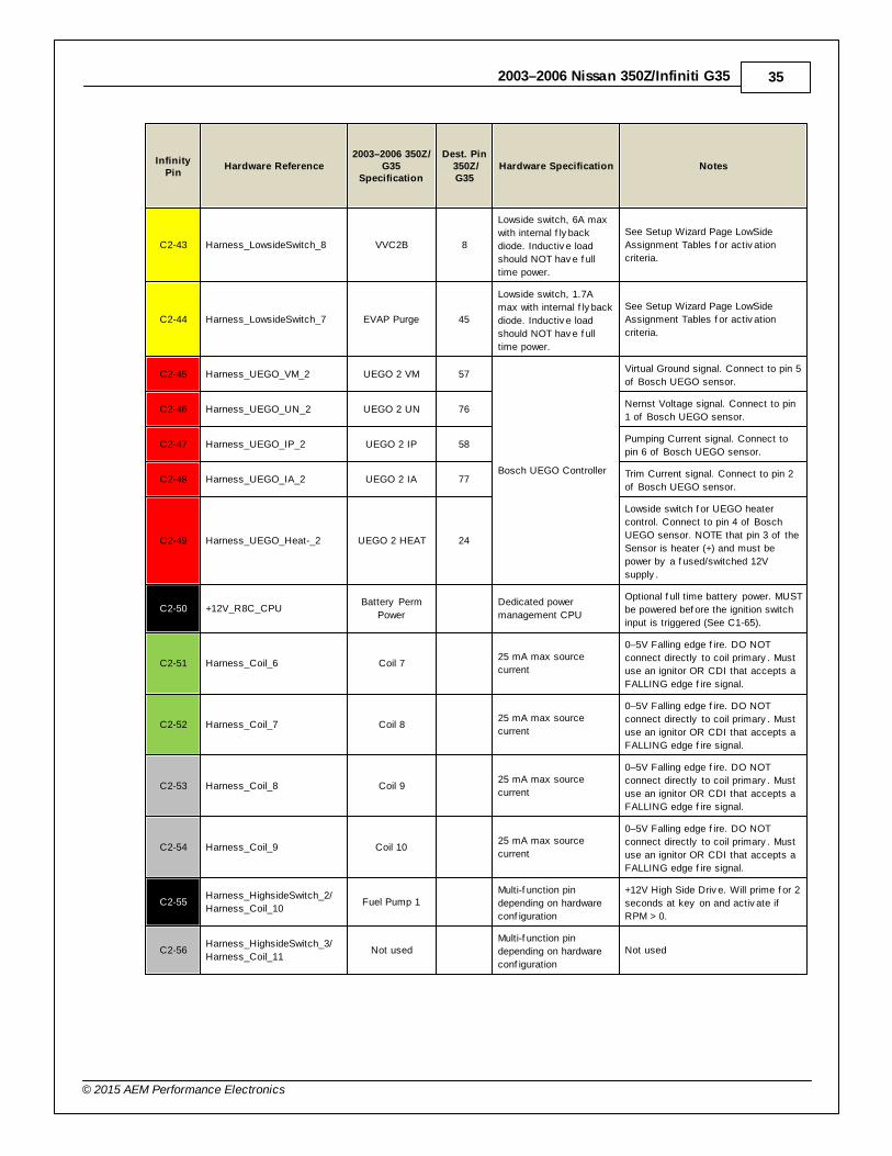
Hardware Specification Notes
C2-43 Harness_LowsideSwitch_8 VVC2B 8
Lowside switch, 6A max
with internal f ly back
diode. Inductiv e load
should NOT hav e f ull
time power.
See Setup Wizard Page LowSide
Assignment Tables f or activ ation
criteria.
C2-44 Harness_LowsideSwitch_7 EVAP Purge 45
Lowside switch, 1.7A
max with internal f ly back
diode. Inductiv e load
should NOT hav e f ull
time power.
See Setup Wizard Page LowSide
Assignment Tables f or activ ation
criteria.
C2-45 Harness_UEGO_VM_2 UEGO 2 VM 57
Bosch UEGO Controller
Virtual Ground signal. Connect to pin 5
of Bosch UEGO sensor.
C2-46 Harness_UEGO_UN_2 UEGO 2 UN 76Nernst Voltage signal. Connect to pin
1 of Bosch UEGO sensor.
C2-47 Harness_UEGO_IP_2 UEGO 2 IP 58Pumping Current signal. Connect to
pin 6 of Bosch UEGO sensor.
C2-48 Harness_UEGO_IA_2 UEGO 2 IA 77Trim Current signal. Connect to pin 2
of Bosch UEGO sensor.
C2-49 Harness_UEGO_Heat-_2 UEGO 2 HEAT 24
Lowside switch f or UEGO heater
control. Connect to pin 4 of Bosch
UEGO sensor. NOTE that pin 3 of the
Sensor is heater (+) and must be
power by a f used/switched 12V
supply .
C2-50 +12V_R8C_CPUBattery Perm
Power
Dedicated power
management CPU
Optional f ull time battery power. MUST
be powered bef ore the ignition switch
input is triggered (See C1-65).
C2-51 Harness_Coil_6 Coil 7 25 mA max source
current
0–5V Falling edge f ire. DO NOT
connect directly to coil primary . Must
use an ignitor OR CDI that accepts a
FALLING edge f ire signal.
C2-52 Harness_Coil_7 Coil 8 25 mA max source
current
0–5V Falling edge f ire. DO NOT
connect directly to coil primary . Must
use an ignitor OR CDI that accepts a
FALLING edge f ire signal.
C2-53 Harness_Coil_8 Coil 9 25 mA max source
current
0–5V Falling edge f ire. DO NOT
connect directly to coil primary . Must
use an ignitor OR CDI that accepts a
FALLING edge f ire signal.
C2-54 Harness_Coil_9 Coil 10 25 mA max source
current
0–5V Falling edge f ire. DO NOT
connect directly to coil primary . Must
use an ignitor OR CDI that accepts a
FALLING edge f ire signal.
C2-55Harness_HighsideSwitch_2/
Harness_Coil_10Fuel Pump 1
Multi-f unction pin
depending on hardware
conf iguration
+12V High Side Driv e. Will prime f or 2
seconds at key on and activ ate if
RPM > 0.
C2-56Harness_HighsideSwitch_3/
Harness_Coil_11Not used
Multi-f unction pin
depending on hardware
conf iguration
Not used
36
© 2015 AEM Performance Electronics
P/N 30-3520
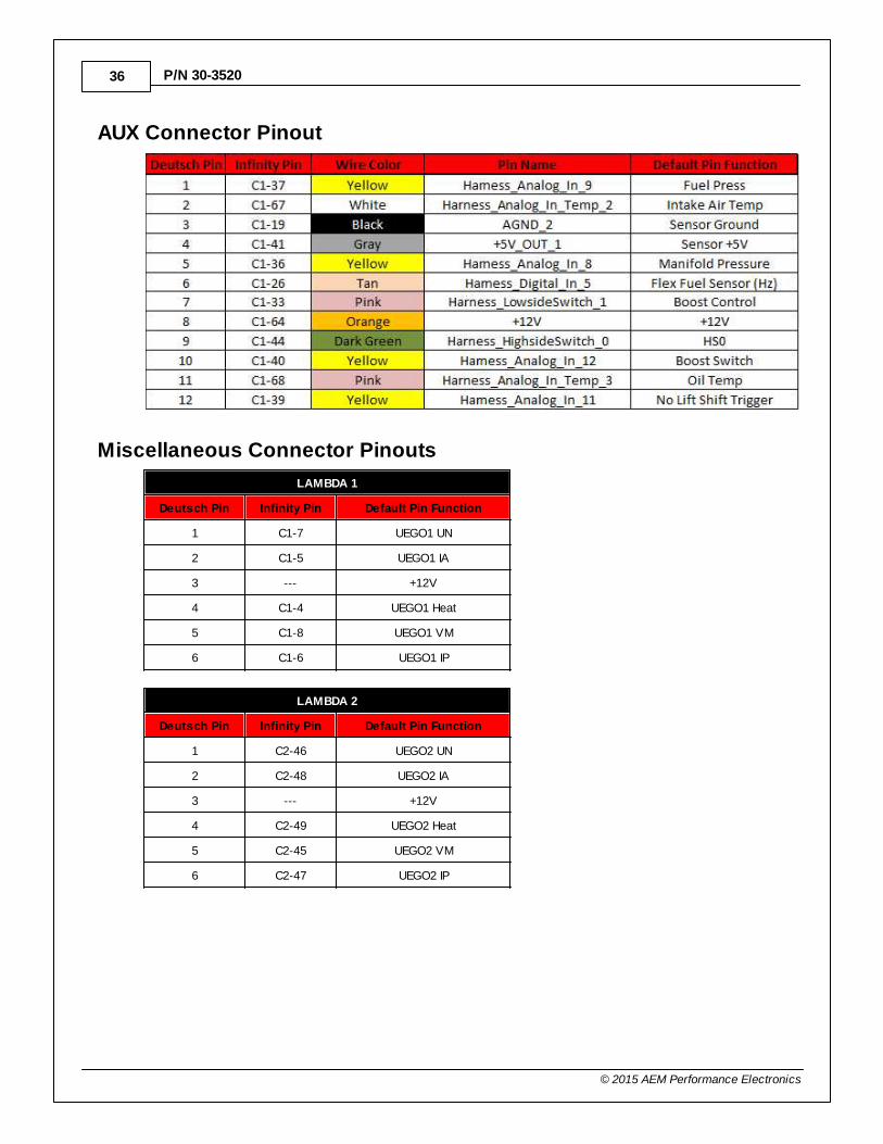
AUX Connector Pinout
Miscellaneous Connector Pinouts
LAMBDA 1
Deutsch Pin Infinity Pin Default Pin Function
1 C1-7 UEGO1 UN
2 C1-5 UEGO1 IA
3 --- +12V
4 C1-4 UEGO1 Heat
5 C1-8 UEGO1 VM
6 C1-6 UEGO1 IP
LAMBDA 2
Deutsch Pin Infinity Pin Default Pin Function
1 C2-46 UEGO2 UN
2 C2-48 UEGO2 IA
3 --- +12V
4 C2-49 UEGO2 Heat
5 C2-45 UEGO2 VM
6 C2-47 UEGO2 IP
2003–2006 Nissan 350Z/Infiniti G35 37
© 2015 AEM Performance Electronics
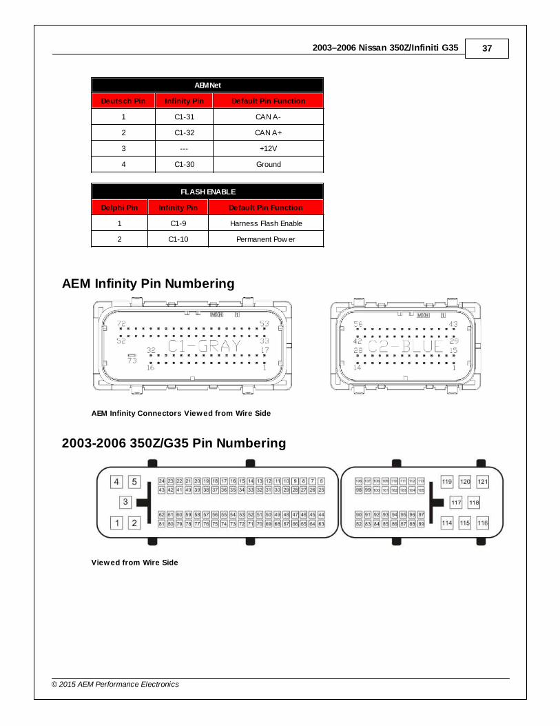
AEMNet
Deutsch Pin Infinity Pin Default Pin Function
1 C1-31 CAN A-
2 C1-32 CAN A+
3 --- +12V
4 C1-30 Ground
FLASH ENABLE
Delphi Pin Infinity Pin Default Pin Function
1 C1-9 Harness Flash Enable
2 C1-10 Permanent Pow er
AEM Infinity Pin Numbering
AEM Infinity Connectors Viewed from Wire Side
2003-2006 350Z/G35 Pin Numbering
Viewed from Wire Side
38
© 2015 AEM Performance Electronics
P/N 30-3520
12 MONTH LIMITED WARRANTY
Advanced Engine Management Inc. warrants to the consumer that all AEM HighPerformance products will be free from defects in material and workmanship for aperiod of twelve (12) months from date of the original purchase. Products that fail withinthis 12-month warranty period will be repaired or replaced at AEM’s option, whendetermined by AEM that the product failed due to defects in material or workmanship.This warranty is limited to the repair or replacement of the AEM part. In no event shallthis warranty exceed the original purchase price of the AEM part nor shall AEM beresponsible for special, incidental or consequential damages or cost incurred due to thefailure of this product. Warranty claims to AEM must be transportation prepaid andaccompanied with dated proof of purchase. This warranty applies only to the originalpurchaser of product and is non-transferable. All implied warranties shall be limited induration to the said 12-month warranty period. Improper use or installation, accident,abuse, unauthorized repairs or alterations voids this warranty. AEM disclaims anyliability for consequential damages due to breach of any written or implied warranty onall products manufactured by AEM. Warranty returns will only be accepted by AEM whenaccompanied by a valid Return Merchandise Authorization (RMA) number. Productmust be received by AEM within 30 days of the date the RMA is issued.
Please note that before AEM can issue an RMA for any electronic product, it is firstnecessary for the installer or end user to contact the EMS tech line at 1-800-423-0046 todiscuss the problem. Most issues can be resolved over the phone. Under nocircumstances should a system be returned or a RMA requested before the aboveprocess transpires.
AEM will not be responsible for electronic products that are installed incorrectly, installedin a non-approved application, misused, or tampered with.
Any AEM electronics product can be returned for repair if it is out of the warranty period.There is a minimum charge of $50.00 for inspection and diagnosis of AEM electronicparts. Parts used in the repair of AEM electronic components will be extra. AEM willprovide an estimate of repairs and receive written or electronic authorization beforerepairs are made to the product.
Recommended