RAN10.0 3900 Series NodeB
Product Description
Issue 03
Date 2008-09-18

Huawei Technologies Co., Ltd. provides customers with comprehensive technical support and service.
Please feel free to contact our local office or company headquarters.
Huawei Technologies Co., Ltd.
Address: Huawei Industrial Base
Bantian, Longgang
Shenzhen 518129
People's Republic of China
Website: http://www.huawei.com
Email: [email protected]
Copyright © Huawei Technologies Co., Ltd. 2008. All rights reserved.
No part of this document may be reproduced or transmitted in any form or by any means without prior
written consent of Huawei Technologies Co., Ltd.
Trademarks and Permissions
and other Huawei trademarks are trademarks of Huawei Technologies Co., Ltd.
All other trademarks and trade names mentioned in this document are the property of their respective
holders.
Notice
The information in this document is subject to change without notice. Every effort has been made in the
preparation of this document to ensure accuracy of the contents, but all statements, information, and
recommendations in this document do not constitute the warranty of any kind, express or implied.

RAN10.0 3900 Series NodeB Product Description
03 (2008-09-18) COMMERCIAL IN CONFIDENCE Page 4 of 59
Contents
1 Introduction.....................................................................................................................6
1.1 3900 Series NodeBs ........................................................................................................................ 6
1.2 Product Features.............................................................................................................................. 7
2 System Architecture .......................................................................................................9
2.1 Product Overview............................................................................................................................. 9
2.2 BBU3900 .......................................................................................................................................... 9
2.2.1 Physical Structure of the BBU3900 ......................................................................................... 9
2.2.2 Hardware Units of the BBU3900 ........................................................................................... 10
2.2.3 Ports on the BBU3900........................................................................................................... 10
2.3 RRU.................................................................................................................................................11
2.3.1 Specifications of the RRU.......................................................................................................11
2.3.2 Physical Structure of the RRU............................................................................................... 12
2.3.3 Ports on the RRU .................................................................................................................. 13
2.4 WRFU............................................................................................................................................. 14
2.4.1 Specifications of the WRFU................................................................................................... 14
2.4.2 Physical Structure of the WRFU............................................................................................ 14
2.4.3 Ports on the WRFU ............................................................................................................... 15
2.5 Auxiliary Devices ............................................................................................................................ 15
2.5.1 APM ....................................................................................................................................... 15
2.5.2 Indoor Macro Cabinet ............................................................................................................ 18
2.5.3 Outdoor RF Cabinet .............................................................................................................. 20
2.5.4 Outdoor Mini Cabinet............................................................................................................. 21
3 Products and Application Scenarios...........................................................................23
3.1 Distributed NodeB—DBS3900 ....................................................................................................... 23
3.1.1 Integrated Application ............................................................................................................ 23
3.1.2 Embedded Application with Existing Site Equipment ............................................................ 24
3.1.3 Outdoor BBU Application....................................................................................................... 24
3.2 Indoor Macro NodeB—BTS3900 ................................................................................................... 25
3.3 Outdoor Macro NodeB—BTS3900A .............................................................................................. 26
3.4 Outdoor Mini NodeB—BTS3900C ................................................................................................. 28
3.5 Multi-Mode Base Station ................................................................................................................ 30
4 Features.........................................................................................................................31
4.1 Advanced Platform Structure.......................................................................................................... 31
4.2 High Integrity and Large Capacity.................................................................................................. 31

RAN10.0 3900 Series NodeB Product Description
03 (2008-09-18) COMMERCIAL IN CONFIDENCE Page 5 of 59
4.3 High Performance .......................................................................................................................... 31
4.4 ATM/IP Dual Stack.......................................................................................................................... 32
4.4.1 ATM........................................................................................................................................ 32
4.4.2 IP ........................................................................................................................................... 32
4.5 Multiple Clock and Synchronization Modes ................................................................................... 33
4.6 HSDPA Services............................................................................................................................. 33
4.7 HSUPA Services............................................................................................................................. 33
4.8 MBMS............................................................................................................................................. 33
4.9 High-Velocity UE Access................................................................................................................ 34
4.10 Antenna Enhancement Technology.............................................................................................. 34
4.11 Same Band Antenna Sharing ....................................................................................................... 34
4.12 OM Platforms ............................................................................................................................... 35
4.13 Environment Adaptability.............................................................................................................. 35
4.14 Capacity Expansion Evolution...................................................................................................... 36
5 Operation and Maintenance.........................................................................................37
5.1 Overview ........................................................................................................................................ 37
5.2 OM Functions ................................................................................................................................. 38
5.2.1 Security Management............................................................................................................ 38
5.2.2 Equipment Management ....................................................................................................... 38
5.2.3 Fault Management................................................................................................................. 38
5.2.4 Software Management .......................................................................................................... 38
5.2.5 Performance Management .................................................................................................... 39
5.2.6 Commissioning Management................................................................................................ 39
5.2.7 Environment Monitoring......................................................................................................... 39
5.2.8 License Management ............................................................................................................ 39
5.2.9 Task Management ................................................................................................................. 39
6 Reliability.......................................................................................................................41
6.1 Overview ........................................................................................................................................ 41
6.2 System Reliability ........................................................................................................................... 41
6.3 Hardware Reliability ....................................................................................................................... 42
6.4 Software Reliability......................................................................................................................... 42
7 Technical Specifications ..............................................................................................44
7.1 Technical Specifications of the BTS3900 ....................................................................................... 44
7.2 Technical Specifications of the BTS3900A..................................................................................... 46
7.3 Technical Specifications of the DBS3900....................................................................................... 49
7.4 Technical specifications of the BTS3900C..................................................................................... 55
8 Acronyms and Abbreviations ......................................................................................59

RAN10.0 3900 Series NodeB Product Description
03 (2008-09-18) COMMERCIAL IN CONFIDENCE Page 6 of 59
1 Introduction
1.1 3900 Series NodeBs
The mobile communications, which takes an ever-changing presence with each passing day, blazes a trail for the upgrade of technologies and products. The growing trend of mobile communications comprises a series of evolution, from GSM to EDGE to EDGE+ and from WCDMA to HSPA to HSPA+ and LTE, and it is worth mentioning that WiMAX also joins the 3G family. To follow the trend, the network operators have to devote more CAPEX and OPEX to the dramatic change of technologies, and therefore they are currently focusing on the merge of multiple network systems into a more cost-effective one.
Upon the transition of mobile networks, the network operators target at the Blue Ocean Strategy and invite innovative and responsive partners. Customer-oriented and innovative, Huawei advocates four basic technological concepts: green, merge, wideband, and evolution. Huawei will take the lead in developing the next-generation base stations and the 3900 series NodeBs, Huawei's fourth generation base stations, will outclass other base stations to benefit operators with future-oriented networks.
Huawei unveils cutting-edge techniques in the 3900 series NodeBs, such as wideband, multi-mode system, and modular design. The 3900 series NodeBs consist of only three basic functional modules, characterized by compact structure, high integration, low power consumption, and easy and quick deployment. Flexible combinations of functional modules and auxiliary devices encourage Huawei to diversify the products. More importantly, the modules for different modes of systems can be installed in one cabinet to work as a base station adapting to different scenarios. Huawei also actively introduces new frequency bands and technologies to well meet operators' requirement for a compact multi-mode mobile network system.
Figure 1-1 shows the basic functional modules and auxiliary devices of the 3900 series NodeBs.
RAN10.0 3900 Series NodeB Product Description
03 (2008-09-18) COMMERCIAL IN CONFIDENCE Page 7 of 59
Figure 1-1 Basic functional modules and auxiliary devices
1.2 Product Features � Adaptable to diversified radio environments
Different combinations of functional modules and auxiliary devices diversify the NodeB products. For example, there are macro NodeB, distributed NodeB, and mini compact NodeB, which operate in different scenarios to better meet different network deployment requirements.
The 3900 series NodeBs provide a platform for the Huawei wireless products. To be specific, the base stations of different network systems such as GSM, WCDMA, CDMA, and WiMAX can share the same cabinet or even share one functional module at the same frequency band (based on the SDR technology), which makes it easy for network operators to choose a site type.
� Greatly reduced Total Cost of Operation (TCO)
The 3900 series NodeBs have many advantages, such as flexible installation, easy site selection, cost-effective solution, and fast network construction. The baseband module (BBU3900) is only 19 inches wide and 2 U high, taking a very small indoor space or taking a place in an outdoor cabinet. The RF module (RRU3900) can be installed close to the antenna without taking any space of the equipment room.
The RRU3804 supports up to four carriers with an output power of 60 W, known as the highest output power of the RRU in the telecom industry. The outstanding performance ensures wide coverage and high throughput. When two carriers are configured for the RRU3804, the number of sites can be reduced by 40%.

RAN10.0 3900 Series NodeB Product Description
03 (2008-09-18) COMMERCIAL IN CONFIDENCE Page 8 of 59
The 3900 series NodeBs use the high-efficiency digital Power Amplifier (PA), which greatly reduces power consumption and helps build a green communication network. Compared with the traditional NodeB, the macro NodeB (BTS3900) has its power consumption reduced by 30%; compared with the traditional macro NodeB, the BTS3900A cabinet, which is in direct-ventilation, has its power consumption reduced by 40%.
Based on the IP switch and multi-carrier technologies, the 3900 series NodeBs support the bandwidth of over 100 Mbit/s, which keeps up with the fast growing mobile data services and provides users with higher data transmission rate.
� Smooth evolution to future radio network systems
The 3900 series NodeBs support smooth evolution to HSPA+ and Long Term Evolution (LTE), thus fully protecting the investment of network operators.
RAN10.0 3900 Series NodeB Product Description
03 (2008-09-18) COMMERCIAL IN CONFIDENCE Page 9 of 59
2 System Architecture
2.1 Product Overview
The 3900 series NodeBs feature a modular design. The basic functional modules are the baseband unit (BBU3900) and the indoor RF unit (WRFU), and outdoor remote RF unit (RRU). The BBU is connected to the RRU or WRFU through CPRI ports and optical cables. The auxiliary devices for the BTS3900 are as follows:
� APM30 power cabinet
� Indoor macro cabinet
� Outdoor cabinet
� Outdoor mini cabinet
The variable combinations of functional modules and auxiliary devices provide flexible site solutions for different scenarios.
2.2 BBU3900
2.2.1 Physical Structure of the BBU3900
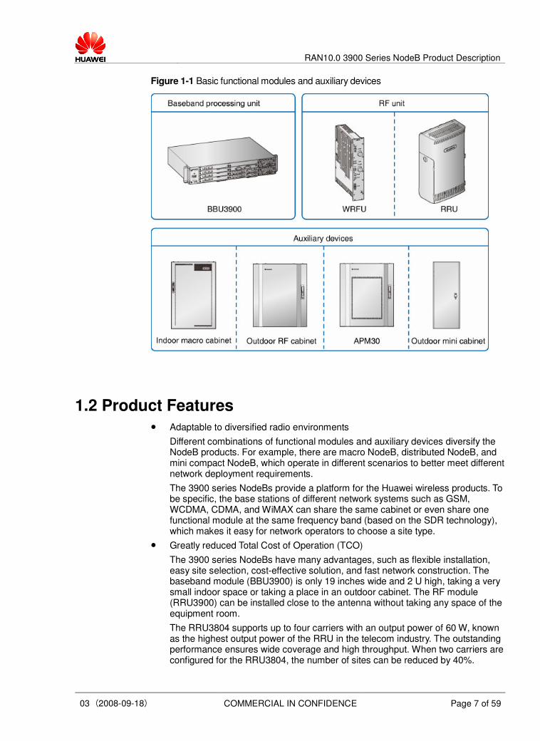
The BBU3900 is a compact case structure that requires a 19-inch-wide and 2-U-high space. It can be installed on a wall, on the staircase, in the storeroom, or in an outdoor cabinet on the existing network. It can be also installed in an outdoor cabinet of the existing network. Figure 2-1 shows the physical structure of the BBU3900.
Figure 2-1 Physical structure of the BBU3900

RAN10.0 3900 Series NodeB Product Description
03 (2008-09-18) COMMERCIAL IN CONFIDENCE Page 10 of 59
2.2.2 Hardware Units of the BBU3900
Basic Hardware Units
The basic hardware units of the BBU3900 are as follows:
� WCDMA Main Processing Transmission (WMPT) unit
� WCDMA BaseBand Processing (WBBP) unit
� Universal Fan (UFAN) unit
� Power module
All the boards support the plug-and-play function and can be configured in the slot as required.
Optional Hardware Units
The optional hardware units of the BBU3900 are as follows:
� Universal E1/T1 Lightning Protection (UELP) unit
� Universal FE Lightning Protection (UFLP) unit
� Universal Satellite card and Clock Unit (USCU)
� Universal Transmission Processing (UTRP) unit
� Universal Environment Interface Unit (UEIU)
The BBU3900 supports diverse configurations from 1 x 1 to 6 x 4 or 3 x 8.
2.2.3 Ports on the BBU3900
Table 2-1 Ports on the basic hardware units of the BBU3900
Board Port Quantity Connector Type Remarks
E1 port 1 DB26 connector One port supporting four E1s
FE electrical port 1 RJ45 connector –
FE optical port 1 SFP connector –
USB port for loading 1 USB connector Software loading
USB port for test 1 USB connector Test port
Serial port for
commissioning
1 RJ45 connector NodeB local maintenance
WMPT
GPS port 1 SMA connector –
WBBP CPRI 3 SFP connector –
PWR 1 3V3 connector –48 V DC power input and +24 V DC
power input
MON0 1 RJ45 connector
UPEU
MON1 1 RJ45 connector
Providing two RS485 monitoring
ports; connecting to the external
monitoring device

RAN10.0 3900 Series NodeB Product Description
03 (2008-09-18) COMMERCIAL IN CONFIDENCE Page 11 of 59
Board Port Quantity Connector Type Remarks
EXT-ALM0 1 RJ45 connector UPEU
EXT-ALM1 1 RJ45 connector
Providing eight dry contact alarm
inputs; connecting to the external
alarm device
Table 2-2 Ports on the optional hardware units of the BBU3900
Board Port Quantity Connector Type Remarks
INSIDE 1 DB25 connector Port for four E1/T1 signal inputs UELP
OUTSIDE 1 DB26 connector Port for four E1/T1 signal outputs
FE0 and FE1
(INSIDE)
2 RJ45 connector Connecting to the NodeB UFLP
FE0 and FE1
(OUTSIDE)
2 RJ45 connector Connecting to the external device. The FE0
(OUTSIDE) connects to the FE0 (INSIDE)
and the FE1 (OUTSIDE) connects to the
FE1 (INSIDE).
RGPS port 3 DB8 connector Connecting to the RGPS signal cable
BITS port 1 SMA connector Connecting to the BITS clock
Clock test port 1 SMA connector Port for testing clock signal output
USCU
Antenna port for
the satellite card
1 SMA connector RF signal input port of the satellite card
UTRP E1/T1 port 2 DB26 connector Providing eight ATM over E1s/T1s or eight
IP over E1s/T1s
MON 1 RJ45 connector
MON1 1 RJ45 connector
Connecting to external monitoring devices
EXT-ALM0 1 RJ45 connector
EXT-ALM1 1 RJ45 connector
Connecting to external alarm devices
UEIU
The UEIU is a monitoring and dry contact extension board for the UPEU.
2.3 RRU
2.3.1 Specifications of the RRU
The RRU is the outdoor RF remote unit that can be installed close to the antenna. The RRU is classified into RRU3804 and RRU3801C based on different output power and
RAN10.0 3900 Series NodeB Product Description
03 (2008-09-18) COMMERCIAL IN CONFIDENCE Page 12 of 59
processing capabilities. Table 2-3 describes the specifications of the RRU3804 and the RRU3801C.
Table 2-3 Specifications of the RRU3801C and the RRU3804
RRU Type RRU3801C RRU3804
Maximum Output Power 40 W 40 W
Number of Carriers Supported 2 4
2.3.2 Physical Structure of the RRU
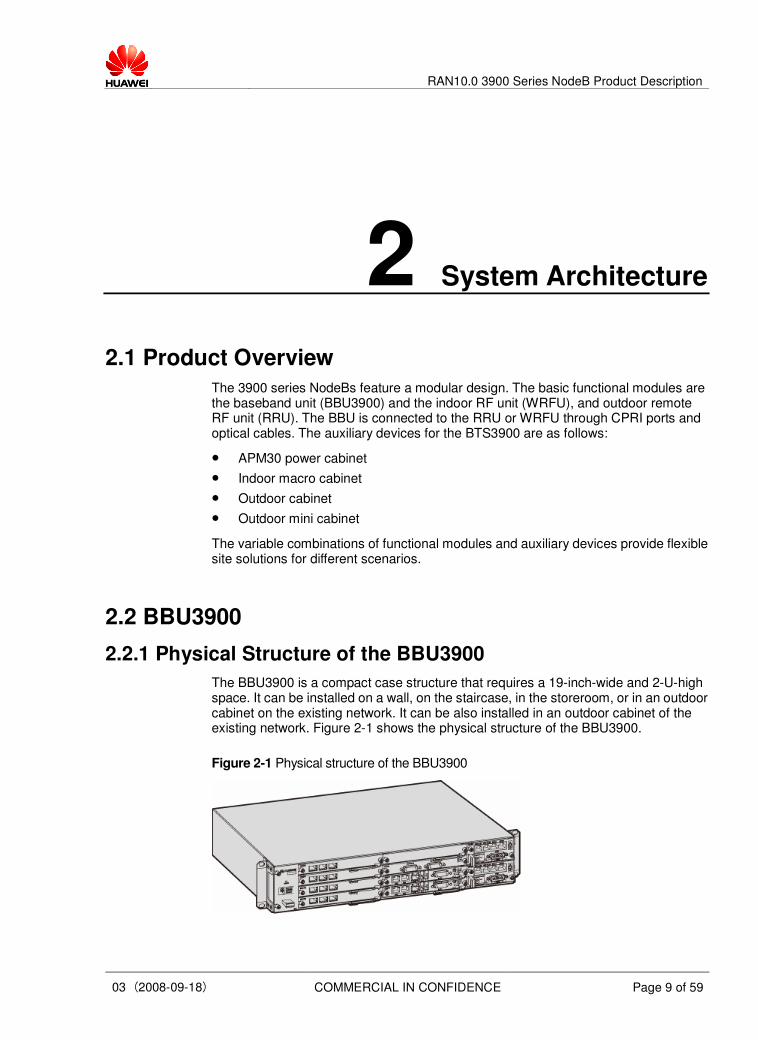
The BBU3900, together with either the RRU3801C or the RRU3804, can form the DBS3900 system. The RRU3801C and the RRU3804 have the same physical structure, as shown in Figure 2-2.
Figure 2-2 Physical structure of the RRU
RAN10.0 3900 Series NodeB Product Description
03 (2008-09-18) COMMERCIAL IN CONFIDENCE Page 13 of 59
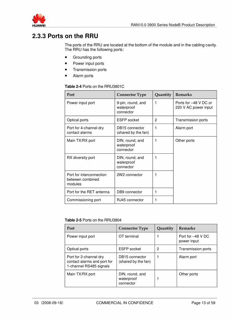
2.3.3 Ports on the RRU
The ports of the RRU are located at the bottom of the module and in the cabling cavity. The RRU has the following ports:
� Grounding ports
� Power input ports
� Transmission ports
� Alarm ports
Table 2-4 Ports on the RRU3801C
Port Connector Type Quantity Remarks
Power input port 9-pin, round, and
waterproof
connector
1 Ports for –48 V DC or
220 V AC power input
Optical ports ESFP socket 2 Transmission ports
Port for 4-channel dry
contact alarms
DB15 connector
(shared by the fan)
1 Alarm port
Main TX/RX port DIN, round, and
waterproof
connector
1
RX diversity port DIN, round, and
waterproof
connector
1
Port for interconnection
between combined
modules
2W2 connector 1
Port for the RET antenna DB9 connector 1
Commissioning port RJ45 connector 1
Other ports
Table 2-5 Ports on the RRU3804
Port Connector Type Quantity Remarks
Power input port OT terminal 1 Port for –48 V DC
power input
Optical ports ESFP socket 2 Transmission ports
Port for 2-channel dry
contact alarms and port for
1-channel RS485 signals
DB15 connector
(shared by the fan)
1 Alarm port
Main TX/RX port DIN, round, and
waterproof
connector
1
Other ports

RAN10.0 3900 Series NodeB Product Description
03 (2008-09-18) COMMERCIAL IN CONFIDENCE Page 14 of 59
Port Connector Type Quantity Remarks
RX diversity port DIN, round, and
waterproof
connector 1
Port for interconnection
between combined modules 2W2 connector
1
2.4 WRFU
2.4.1 Specifications of the WRFU
The WRFU is categorized into 40 W WRFU and 80 W WRFU based on different output power and processing capabilities. The 40 W WRFU and 80 W WRFU have the same physical structure, dimensions, weight, and physical ports.
Table 2-6 Specifications of the WRFU
WRFU Type 80 W WRFU 40 W WRFU
Maximum Output Power 80 W 40 W
Number of Carriers Supported 4 2
2.4.2 Physical Structure of the WRFU
The WRFU can be housed in an indoor cabinet or an outdoor cabinet. Figure 2-3 shows the physical structure of the WRFU.
Figure 2-3 Physical structure of the WRFU

RAN10.0 3900 Series NodeB Product Description
03 (2008-09-18) COMMERCIAL IN CONFIDENCE Page 15 of 59
2.4.3 Ports on the WRFU
Table 2-7 Ports on the WRFU
Port Connector Type Quantity Remarks
Power port 3V3 connector 1 Port for –48 V DC power
input
Port for transceiving
antenna signals
N female
connector
2 Port for connecting the
antenna system
CPRI ports SFP female
connector
2 Ports for connecting the
BBU
Ports for transmitting
diversity RX signals
QMA female
connector
2 Ports for cascading
WRFUs
Commissioning port RJ45 connector 1 Commissioning port
2.5 Auxiliary Devices
2.5.1 APM
The Advanced Power Module (APM), an outdoor power backup system that provides –48 V DC power and backup power for the distributed NodeBs, outdoor macro NodeBs, and mini NodeBs. In addition, it provides installation space for the BBU3900 and other devices. The APM is categorized into APM30 and APM100.
The APM30 features a compact and lightweight design. It can be installed on a pole or on the ground. The 12 Ah, 24 Ah, and 36 Ah batteries can be installed in the APM30 cabinet. The APM100 can be installed on the ground. The 50 Ah or 100 Ah batteries can be configured in the APM100. The APM30 contains the following units:
� Power Supply Unit (PSU)
� Power Monitoring Unit (PMU)
� Power Distribution Unit (PDU)
� APM Power unit Interface Board (APMI)
� Temperature monitoring unit
� 24 Ah batteries
Figure 2-4 shows the internal structure of the APM30 and Figure 2-12 shows that of the APM100.

RAN10.0 3900 Series NodeB Product Description
03 (2008-09-18) COMMERCIAL IN CONFIDENCE Page 16 of 59
Figure 2-4 Internal structure of the APM30
Figure 2-5 Internal structure of the APM100

RAN10.0 3900 Series NodeB Product Description
03 (2008-09-18) COMMERCIAL IN CONFIDENCE Page 17 of 59
Table 2-8 Technical specifications of the APM
Item APM30 Specification APM100 Specification
Dimensions (width
x height x depth)
(with the base
excluded)
600 mm × 700 mm × 480 mm 600 mm x 1130 mm x 600
mm
Weight (with
batteries and user
equipment
excluded)
< 65 kg ≤ 88 kg
Engineering
specifications
Working
temperature
-40ºC to +45ºC (with 1120 W/m2
solar radiation)
–40ºC to +50ºC (without solar
radiation)
When the ambient temperature is
lower than –20°C, an AC heater is
required.
Northern type: –40ºC to
+45ºC
Southern type: –5ºC to
+45ºC
Input voltage � Rated voltage: 200 V AC to 240 V AC Permissible voltage range: 176 V AC to 290 V AC
� Rated voltage: 100/200 V AC to 120/240 V AC
Permissible voltage range: 90/180 V AC to 135/270
� Rated voltage: 120/208 V AC to 127/220 V AC
Permissible voltage range: 105/176 V AC to 150/260 V AC
Frequency of the
rated voltage
50/60 Hz
AC input
Frequency of input
voltage
45 Hz to 65 Hz 40 Hz to 65 Hz
Output voltage
range
–58 V DC to –44 V DC DC output
DC outputs Working with the distributed NodeB:
LLVD: 20 A x 6
BLVD: 12 A x 2; 4 A x 2
Maximum outputs (reserved): 4 A x 2
Working with the separated NodeB:
LLVD: 30 A x 4
BLVD: 12 A x 2; 4 A x 4
Maximum outputs (reserved): 4 A x 4
16 A x 4: 4 outputs
32 A x 2: 2 outputs
–48 V 24 Ah
built-in batteries
5 U – Space for
user
equipment No built-in
batteries
7 U –

RAN10.0 3900 Series NodeB Product Description
03 (2008-09-18) COMMERCIAL IN CONFIDENCE Page 18 of 59
Item APM30 Specification APM100 Specification
48 V 100 Ah
built-in batteries
– –
2.5.2 Indoor Macro Cabinet
The indoor macro cabinet houses the BBU3900 and the WRFU. In addition, the indoor macro cabinet provides functions such as power distribution and surge protection. The indoor macro cabinet takes a small footprint and is easy to install. In addition, two cabinets can be installed in stack mode. All these features cater to the requirements of indoor centralized installation and fast network construction. An indoor macro cabinet accommodates up to six WRFUs. The indoor macro cabinet supports all the network systems (UMTS, GSM, and LTE) of the BTS3900, thus saving installation space and facilitating smooth evolution.
The indoor macro cabinet supports –48 V DC, +24 V DC, and 220 V AC power inputs. If configured with suitable power modules, the +24 V DC or 220 V AC power is converted into –48 V DC power for the WRFU and BBU.
When two cabinets are installed in stack mode, the upper cabinet should be a -48 V DC cabinet, and the lower cabinet can be either a +24 V DC cabinet or a 220 V AC cabinet, depending on power configuration.
The cabinet structure varies with the power input. Figure 2-6 shows the single indoor cabinet with –48 V DC power. Figure 2-7 shows the single indoor cabinet with +24 V DC power. Figure 2-8 shows the single indoor cabinet with 220 V AC power. Figure 2-9 shows two cabinets in stack mode.
Figure 2-6 Single indoor cabinet (–48 V)

RAN10.0 3900 Series NodeB Product Description
03 (2008-09-18) COMMERCIAL IN CONFIDENCE Page 19 of 59
Figure 2-7 Single indoor cabinet (+24 V)
Figure 2-8 Single indoor cabinet (220 V)
RAN10.0 3900 Series NodeB Product Description
03 (2008-09-18) COMMERCIAL IN CONFIDENCE Page 20 of 59
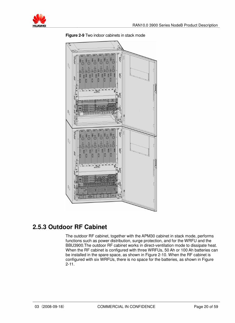
Figure 2-9 Two indoor cabinets in stack mode
2.5.3 Outdoor RF Cabinet
The outdoor RF cabinet, together with the APM30 cabinet in stack mode, performs functions such as power distribution, surge protection, and for the WRFU and the BBU3900.The outdoor RF cabinet works in direct-ventilation mode to dissipate heat. When the RF cabinet is configured with three WRFUs, 50 Ah or 100 Ah batteries can be installed in the spare space, as shown in Figure 2-10. When the RF cabinet is configured with six WRFUs, there is no space for the batteries, as shown in Figure 2-11.

RAN10.0 3900 Series NodeB Product Description
03 (2008-09-18) COMMERCIAL IN CONFIDENCE Page 21 of 59
Figure 2-10 Outdoor RF cabinet with three WRFUs
Figure 2-11 Outdoor RF cabinet with six WRFUs
2.5.4 Outdoor Mini Cabinet
The outdoor mini cabinet performs functions such as power distribution and surge protection for the BBU3900. The BBU3900 can be installed in an outdoor mini cabinet to work as an outdoor BBU, thus achieving the outdoor application of the compact mini NodeB.
The outdoor mini cabinet has a built-in heat exchanger. If the AC power is used, the cabinet must be configured with an EPS30-4815A and an SPD (AC); if the DC power is used, the cabinet must be configured with a DC power distribution box, as shown in Figure 2-12.

RAN10.0 3900 Series NodeB Product Description
03 (2008-09-18) COMMERCIAL IN CONFIDENCE Page 22 of 59
Figure 2-12 Internal structure of the outdoor mini cabinet

RAN10.0 3900 Series NodeB Product Description
03 (2008-09-18) COMMERCIAL IN CONFIDENCE Page 23 of 59
3 Products and Application Scenarios
3.1 Distributed NodeB—DBS3900
As demand for environmental protection as well as lease cost has increased, the site selection has become a bottleneck in network deployment. It is increasingly difficult to adopt 2G/3G co-siting or to select a new site.
The distributed NodeB (DBS3900) developed by Huawei features high integration, easy installation, and low power consumption. All these features can facilitate site reselection and 2G/3G co-siting. In addition, the WRRU can be installed close to the antenna. In this way, the feeder consumption is reduced and system coverage is improved.
3.1.1 Integrated Application
If only the AC power is available at a new outdoor 3G site and power backup device is required, the combination of DBS3900 and APM can function as an outdoor macro NodeB. Figure 3-1 shows the typical configuration of DBS3900 + APM.
This configuration has the following features:
� The BBU3900 and transmission equipment can be installed in the APM cabinet and the RRU can be installed close to the antenna.
� The APM provides installation space and outdoor protection for the BBU3900 and supplies –48 V DC power to the BBU3900 and the WRRU. In addition, the APM manages and monitors the batteries and provides surge protection for the batteries.
� The APM30 can be configured with 12 Ah, 24 Ah, or 36 Ah built-in batteries and the APM100 can be configured with 50 Ah or 100 Ah built-in batteries. Whether the APM30 or the APM100 should be used depends on the required power back period.

RAN10.0 3900 Series NodeB Product Description
03 (2008-09-18) COMMERCIAL IN CONFIDENCE Page 24 of 59
Figure 3-1 DBS3900 + APM
3.1.2 Embedded Application with Existing Site Equipment
For the 2G/3G co-siting scenario, the BBU3900 can be installed in a standard 19-inch-wide and 2-U-high cabinet, and the WRRU can be installed close to the antenna, as shown in Figure 3-2. The BBU3900 and the WRRU can share the power backup system, transmission system, and antenna system of the BTS in the 2G network. In this way, operators can launch 3G services on the existing 2G network at a very low cost.
Figure 3-2 Embedded application based on existing site equipment
3.1.3 Outdoor BBU Application
For the 2G/3G co-siting scenario, the BBU3900 can be installed in the outdoor mini cabinet to function as an outdoor BBU. The WRRU can be installed close to the antenna for easy and quick deployment, as shown in Figure 3-3.

RAN10.0 3900 Series NodeB Product Description
03 (2008-09-18) COMMERCIAL IN CONFIDENCE Page 25 of 59
Figure 3-3 Outdoor BBU application
3.2 Indoor Macro NodeB—BTS3900
The BTS3900, as shown in Figure 3-4, is applicable to indoor scenarios such as centralized installation and relocation. The BTS3900, as one of the most compact indoor macro NodeBs in the telecommunication industry, boasts large capacity and sound scalability. It has a small footprint and supports the GSM and WCDMA dual-mode application.

RAN10.0 3900 Series NodeB Product Description
03 (2008-09-18) COMMERCIAL IN CONFIDENCE Page 26 of 59
Figure 3-4 Indoor cabinet macro NodeB
3.3 Outdoor Macro NodeB—BTS3900A
The BTS3900A is applicable to the outdoor scenarios such as centralized installation and replacement of the macro NodeB. The BTS3900A consists of the outdoor RF cabinet and the APM30 that are installed in stack mode. The BBU3900 is installed in the APM30, and the WRFU is installed in the RF cabinet. Configurations of the BTS3900A vary with different application scenarios, as shown in Figure 3-5 and Figure 3-6.
As the most compact outdoor cabinet macro NodeB in the industry, features light weight and easy transportation due to its stacking design. The RF modules in GSM, UMTS, and LTE modes can share one RF cabinet, which saves installation space and facilitates smooth evolution.

RAN10.0 3900 Series NodeB Product Description
03 (2008-09-18) COMMERCIAL IN CONFIDENCE Page 27 of 59
Figure 3-5 Cabinet macro NodeB (1)

RAN10.0 3900 Series NodeB Product Description
03 (2008-09-18) COMMERCIAL IN CONFIDENCE Page 28 of 59
Figure 3-6 Cabinet macro NodeB (2)
3.4 Outdoor Mini NodeB—BTS3900C
The BTS3900C applies to the new outdoor 3G site environments such as tunnels, hot spots, places without equipment rooms, and marginal networks.
The BTS3900C supports –48 V DC power and 220 V AC power. If –48 V DC power is used, the mini cabinet must be configured with a DC power distribution box, as shown in Figure 3-7. If 220 V AC power is used, the mini cabinet must be configured with an EPS30-4815A and an SPD (AC), as shown in Figure 3-8. The BTS3900C can be installed on the pole, against the wall, or on the ground. The stand or support of other types can be applied to the installation of the BTS3900C on the ground.

RAN10.0 3900 Series NodeB Product Description
03 (2008-09-18) COMMERCIAL IN CONFIDENCE Page 29 of 59
Figure 3-7 Outdoor mini NodeB with –48 V DC power
Figure 3-8 Outdoor mini NodeB with 220 V AC power

RAN10.0 3900 Series NodeB Product Description
03 (2008-09-18) COMMERCIAL IN CONFIDENCE Page 30 of 59
3.5 Multi-Mode Base Station
The 3900 series NodeBs feature a unified platform and a modular design. Therefore, co-siting of modules in GSM, UMTS, or LTE mode can be supported, the baseband processing units and RF modules can share the same hardware platform, and modules in different modes can be located in one cabinet to support multi-mode application. This helps implement smooth evolution from GSM to UMTS or LTE.
With baseband modules for different modes configured in one cabinet, the base station can support the GSM only mode, UMTS only mode, or GSM/UMTS dual mode. In addition, with the baseband modules for LTE mode configured in the future, the base station can support the GSM/UMTS/LTE multi-mode application.
With RF modules for different modes configured in one cabinet, the base station can support the GSM only mode, UMTS only mode, or GSM/UMTS dual mode.
The RF modules in UMTS mode are LTE-ready in hardware. Thus the base station can support UMTS/LTE dual-mode through software upgrade in the same frequency band.
Figure 3-9 and Figure 3-10 show the multi-mode base stations for indoor and outdoor application respectively.
Figure 3-9 Multi-mode base station for indoor application
Figure 3-10 Multi-mode base station for outdoor application

RAN10.0 3900 Series NodeB Product Description
03 (2008-09-18) COMMERCIAL IN CONFIDENCE Page 31 of 59
4 Features
4.1 Advanced Platform Structure
The advanced platform structure of the 3900 series NodeBs is described as follows:
� The 3900 series NodeBs that adopt the IP switch-based Huawei platform support the GU co-cabinet application, HSPA+, and smooth evolution to LTE.
� The 3900 series NodeBs introduce the module-sharing concept, that is, the distributed NodeB, cabinet macro NodeB, and compact mini NodeB share all baseband and RF modules. The three types of basic modules form different NodeB products that apply to different scenarios, thus lowering CAPEX and OPEX.
� The dual-star GE IP switch technology enables exchange of large amount of internal data and satisfies more data traffic needs for HSPA+ and LTE in the future.
� The hot-swappable BBU3900 provides eight slots for boards and supports smooth capacity expansion and evolution.
� The combination of the duplexer and Transceiver Unit (TRU) in the RF module enhances the integrity of RF parts and meets the future requirements of the minimized, high-efficiency, and low-cost NodeBs.
� A minimized NodeB cabinet is easy to carry and install, and the stacked NodeB cabinets take up a small footprint.
4.2 High Integrity and Large Capacity
The 3900 series NodeBs are highly integrated and large in capacity:
� The BBU3900 contains highly integrated chips and features large capacity. A single BBU3900 supports 24 cells, with 1,536 UL CEs and 1,536 DL CEs. It also supports HSDPA and HSUPA services.
� A single RRU3804 or WRFU supports the 4-carrier configuration. When the NodeB evolves from 1 x 1 to 1 x 4 or from 3 x 1 to 3 x 4, no extra RRU or WRFU is required.
4.3 High Performance
The high performance of the 3900 series NodeBs are described as follows:

RAN10.0 3900 Series NodeB Product Description
03 (2008-09-18) COMMERCIAL IN CONFIDENCE Page 32 of 59
� The 3900 series NodeBs feature high receiver sensitivity. The 2-way receiver sensitivity is higher than –129.3 dBm without the Tower Amplification (TMA).
� The WRFU supports 80 W output power and the RRU3804 supports 60 W output power, which means that the PAs of the 3900 series NodeBs increase to 40%.
� The 3900 series NodeBs support open-loop TX diversity and closed-loop TX diversity to enhance downlink coverage and capacity.
� A single RRU3804 (with an SRXU) supports 4-way RX diversity to enhance antenna receiver sensitivity.
4.4 ATM/IP Dual Stack
4.4.1 ATM
In ATM transmission, the 3900 series NodeBs support the following modes:
� User-Network Interface (UNI) mode when transmission resources are inadequate and traffic is low.
� Inverse Multiplexing on ATM (IMA) mode when there are rich transmission resources. This mode features high reliability, high-speed transmission, and low latency.
� Fractional ATM
4.4.2 IP
The IP transmission, based on IPs, supports the transmission of various data services on low-rate links. In this mode, the IP transmission resources are fully utilized and operators' investment is greatly reduced.
In IP transmission, the 3900 series NodeBs support the following technologies:
� Native IP transmission that requires no additional hardware. Compared with the PWE3 technology, Native IP is more efficient, cost-effective, and independent of PWE3 external devices.
� IP over E1, to fully utilize the E1 resources of the existing network and to offer a complete solution of IP transmission
� Fractional Point-to-Point Protocol (PPP)
� ATM and IP dual stack, to protect operators' early investment in ATM transmission
� Compression and multiplexing technology, namely the multiplexing of PPP header compression, PPPMUX, and IPHC, to raise the transmission rate over E1 ports. With the technology of IPHC + PPP compression + PPPMUX, the E1 transmission rate of the 12.2 kbit/s voice service rises by up to 37%.
� FP Multiplex (MUX), to reduce the number of Medium Access Control (MAC) headers by multiplexing packets and to raise the transmission rate over FE ports. With this technology, the FE transmission rate of the 12.2 kbit/s voice service rises by up to 40%.
� Hybrid transmission, which enables services to meet different QoS requirements and then to allocate different transmission paths. For example, hybrid transmission enables real-time services to travel on electrical ports, such as E1/T1 ports, and non-real-time services to travel on Ethernet ports.

RAN10.0 3900 Series NodeB Product Description
03 (2008-09-18) COMMERCIAL IN CONFIDENCE Page 33 of 59
4.5 Multiple Clock and Synchronization Modes
The 3900 series NodeBs support multiple clock and synchronization modes to fulfill different clock networking requirements:
� The upper-level clock is extracted from the Iub interface and is set by default.
� The 3900 series NodeBs adopt the GPS to achieve clock synchronization.
� The external clock synchronization refers to the 2 MHz clock on the transmission equipment.
� Without additional hardware, the system supports the IP clock through software upgrade, which provides a high-performance and low-cost clock solution for the IP transmission.
� The internal clock, an internal stratum-3 clock, ensures that the NodeB without the external clock still works properly for at least 90 days.
4.6 HSDPA Services
The 3900 series NodeBs support HSDPA services in the following aspects:
� One carrier supports both HSDPA and R99/R4 services.
� The peak downlink rate of a single UE is up to 14.4 Mbit/s.
� A single cell supports up to 15 HS-PDSCH codes and dynamic code resource allocation.
� The 3900 series NodeBs support all 12 UE categories and rates.
� A single cell supports 64 HSDPA subscribers.
� The 3900 series NodeBs support dynamic power allocation.
� The 3900 series NodeBs support QPSK and 16QAM to enhance spectrum utilization.
4.7 HSUPA Services
The 3900 series NodeBs support HSUPA services in the following aspects:
� One carrier supports both HSUPA and R99/R4 services.
� The 3900 series NodeBs support E-DCH TTI of 10 ms and 2 ms.
� The peak uplink data rate of an HSUPA subscriber is up to 5.76 Mbit/s.
� A single cell supports 60 HSUPA subscribers.
� The 3900 series NodeBs support 2 ms Received Total Wideband Power (RTWP) fast measurement to enhance the reliability of uplink load.
4.8 MBMS
The 3900 series NodeBs support the Multimedia Broadcast and Multicast Service (MBMS) in the following aspects:

RAN10.0 3900 Series NodeB Product Description
03 (2008-09-18) COMMERCIAL IN CONFIDENCE Page 34 of 59
� The 3900 series NodeBs support the setup, reconfiguration, and deletion of the MBMS notification Indicator Channel (MICH), and handle related signaling configuration.
� Each cell supports 16 Secondary Common Control Physical Channels (SCCPCHs).
� Each SCCPCH supports 4 Forward Access Channels (FACHs).
� Each cell supports 63 MBMS channels.
4.9 High-Velocity UE Access
The 3900 series NodeBs support a moving speed of up to 400 km/h. With this feature, UEs on high-speed vehicles, such as express railways and maglev trains, can still communicate properly.
4.10 Antenna Enhancement Technology
The antenna enhancement technology enables the 3900 series NodeBs to perform the following functions:
� Supporting the RET antenna to optimize network coverage, reduce interference, and enlarge system capacity
� Supporting remote batch OM, batch software upgrade, and batch RET tilt adjustment
� Supporting automatic scanning of the RET antenna
� Supporting the Antenna Interface Standard Group (AISG) 1.1 and AISG 2.0 standard interfaces
� Supporting the cascading of RET antennas and controlling the tilt of the 2G RET antenna through the 3G site
4.11 Same Band Antenna Sharing
To implement the same band antenna sharing with low insertion loss, the Same-band Antenna Sharing Unit (SASU) and Same-band Antenna Sharing Adapter (SASA) are introduced to reduce costs of network deployment.
The SASU applies to two scenarios, namely the antenna shared by 2G and 3G systems and the antenna shared by two 3G systems. The SASU that enables two different systems at the same band to share one antenna system is an important part of the same band antenna sharing solution. It can greatly reduce the cost and time of the 3G network construction.
The SASU supports 900 MHz and 2100 MHz frequency bands.
The SASA is also an important part of the same band antenna sharing solution. It will cause an insertion loss of 0.8 dB in the downlink, but it can integrate transmit carriers from two antennas into one antenna, without affecting GSM network performance.

RAN10.0 3900 Series NodeB Product Description
03 (2008-09-18) COMMERCIAL IN CONFIDENCE Page 35 of 59
4.12 OM Platforms
The 3900 series NodeBs support two OM platforms, namely the LMT and the M2000, with which the 3900 series NodeBs perform the following OM functions:
� Supporting local maintenance, remote maintenance, and reverse maintenance
� Supporting Bootstrap Protocol (BOOTP) and Dynamic Host Configuration Protocol (DHCP) when data is not configured or the NodeB is faulty, the NodeB automatically sets up an OM channel to enhance system reliability and to perform remote troubleshooting
� Supporting configuration baseline and simplifies the configuration rollback process to roll back configuration more reliably
� Providing the intelligent out-of-service function. Before the NodeB is out of service, the UE is handed over to another 2G or 3G cell when the NodeB gradually reduces the cell pilot power. Such a handover prevents service interruption
� Providing the topology scanning of RRU networking and automatically monitors the topology to free manual operations
� Providing the complete system self-testing function to support local software commissioning
4.13 Environment Adaptability
The 3900 series NodeBs provide a comprehensive solution applicable to different environments.
� The 3900 series NodeBs fulfill the following outdoor environmental conditions:
− Waterproof and dustproof design of the RRU complies with the International Protection (IP) 65 standard. The RRU provides class-1 protection against damp, mould, and salt mist. The rack for RRUs can prevent them from exposure to solar radiation and adverse environments. The RRU works normally in the solar radiation of 1,120 W/m2 with the temperature ranging from –40°C to +50°C.
− The waterproof and dustproof design of the BTS3900A complies with the IP55 standard. The BTS3900A provides class-1 protection against damp, mould, and salt mist. The BTS3900A cabinet can resist solar radiation and adverse environments. The BTS3900A works normally in the solar radiation of 1,120 W/m
2 with the temperature ranging from –40°C to +45°C.
− The waterproof and dustproof design of the BTS3900C complies with the IP55 standard. The BTS3900C provides class-1 protection against damp, mould, and salt mist. The BTS3900C works normally in the temperature ranging from –40°C to +45°C with the solar radiation of 1,120 W/m
2 and the temperature
ranging from –40°C to +50°C without solar radiation.
� The 3900 series NodeBs fulfill the indoor environmental conditions when they comply with the IP20 standard. The BBU3900 works normally within the temperature ranging from –20°C to +55°C and the BTS3900 works normally within the temperature ranging from –20°C to +50°C.
� The 3900 series NodeBs also provide a comprehensive auxiliary product solution regarding the following aspects:
− Power distribution

RAN10.0 3900 Series NodeB Product Description
03 (2008-09-18) COMMERCIAL IN CONFIDENCE Page 36 of 59
− Surge protection
− Transmission cables
− Transmission equipment installation
− Power backup
4.14 Capacity Expansion Evolution
Based on the Huawei IP switch platform, the 3900 series NodeBs support the GSM-WCDMA dual-mode cabinet. In addition, the 3900 series NodeBs are HSPA+ ready in hardware. This facilitates smooth evolution to the LTE.
� The BBU3900 is HSPA+ Phase 1 (downlink 64QAM and MIMO 2x2) ready in hardware.
� The BBU3900 supports HSPA+ Phase 2 (uplink 16QAM) by adding baseband processing boards.
� The BBU3900 supports the LTE by adding baseband processing boards.
� The RRU and WRFU are HSPA+ and LTE ready in hardware.

RAN10.0 3900 Series NodeB Product Description
03 (2008-09-18) COMMERCIAL IN CONFIDENCE Page 37 of 59
5 Operation and Maintenance
5.1 Overview
Based on the Man Machine Language (MML) and Graphic User Interface (GUI), the 3900 series NodeBs provide a universal OM mechanism irrelevant to hardware and take into consideration customers' requirements for equipment operation and maintenance. In one word, they offer highly customized and powerful OM functions. Figure 5-1 shows the OM systems of the 3900 series NodeBs.
Figure 5-1 OM systems of the 3900 series NodeBs
M2000: Huawei Mobile Element Management System
LMT: Local Maintenance Terminal
NodeB: UMTS Base Transceiver Station
RNC: Radio Network Controller
The LMT and M2000 are two OM systems that implement comprehensive maintenance for the 3900 series NodeBs.
� LMT
One LMT is used to maintain one NodeB. The LMT supports the local maintenance by directly connecting to the NodeB or the remote maintenance by connecting to the NodeB through maintenance channels. The LMT performs the following functions:
− Data configuration

RAN10.0 3900 Series NodeB Product Description
03 (2008-09-18) COMMERCIAL IN CONFIDENCE Page 38 of 59
− Status monitoring (through emulation panel)
− Alarm monitoring
− Software upgrade
− Testing and commissioning
The LMT also maintains the NodeB through MML and GUI.
� M2000
The M2000 is the network management center of the WCDMA Radio Access Network (WRAN), which remotely maintains the NodeB in batches.
The M2000 performs the following functions:
− Data configuration (CME-based)
− Alarm monitoring
− Performance monitoring
− Software upgrade
The M2000 also maintains the NodeB through MML and GUI. It can support different types of NodeB and different versions of software at the same time.
5.2 OM Functions
The 3900 series NodeBs provide a universal OM mechanism independent of hardware. The mechanism includes security management, equipment management, fault management, software management, and performance management.
5.2.1 Security Management
Security management is to manage the connection between NodeB software and Operation and Maintenance Center (OMC) (that is, the LMT or M2000 in the WRAN), user authentication, encryption, and forward resolution of interface messages.
5.2.2 Equipment Management
Equipment management provides data configuration and status management of all internal equipment (boards and modules) and external equipment (power supply, EMI, and RET) of the NodeB.
5.2.3 Fault Management
Fault management accomplishes functions such as fault detection, alarm reporting, alarm-related troubleshooting, fault isolation and self-healing.
5.2.4 Software Management
Software management provides software downloading and activation, patch upgrade, file uploading and downloading functions in addition to consistency check of software and hardware versions, version management, and software version upgrade.
Software management is also a means to upgrade software locally through the USB port on the BBU3900 panel instead of through a PC.

RAN10.0 3900 Series NodeB Product Description
03 (2008-09-18) COMMERCIAL IN CONFIDENCE Page 39 of 59
5.2.5 Performance Management
Performance management includes subscription of NodeB performance counters, periodical control of performance statistics, and measurement, sampling, storage, and reporting of performance counters.
5.2.6 Commissioning Management
The 3900 series NodeBs perform commissioning functions in two ways, namely universal testability frame and specific testing/commissioning.
� The universal testability frame provides a universal testing mechanism to facilitate the future extended testing. It also provides a common test template regarding immediate test, periodical task test, and performance counter test, which facilitates the template-based extended testing in the future.
� The NodeB provides a variety of testing and commissioning functions for easy maintenance and fault diagnosis. The specific testing/commissioning has the following functions:
− E1/T1 online BER test, RTWP test, and CPU usage test
− NodeB logs and one-push uploading of NodeB logs
− Interface tracing of Iub and internal interface
− Local serial port commissioning and serial port redirection
5.2.7 Environment Monitoring
The 3900 series NodeBs are attendance-free and widely applicable, which requires a sound environment monitoring system to ensure the normal running of the NodeB equipment and to handle all possible emergencies.
The environment monitoring system provides customized solutions regarding door control, infrared, smoke, water immersion, humidity, and temperature. Users can also define external alarms.
5.2.8 License Management
The M2000 is responsible for applying for and activating WRAN licenses. It delivers license control items to a NodeB and through these items controls the current services and capacity of the NodeB. The function control items include HSDPA, OTSR, HSUPA, and MBMS, while the resource control items include the number of CEs, number of sectors and carriers, and power control.
The 3900 series NodeBs also provide interfaces for querying license control items, clearing license, and setting license function switches.
5.2.9 Task Management
The 3900 series NodeBs provide maintenance for the BBU, RRU, RET, and EMI.
The 3900 series NodeBs comply with the Antenna Line Device (ALD) protocol of AISG2.0 and 3GPP, and downwards compatible with the AISG1.1 protocol.
The 3900 series NodeBs provide the RET antenna equipment with all OM functions, including auto scanning, data configuration (setting of the antenna tilt and TMA gain), status query, and fault reporting.

RAN10.0 3900 Series NodeB Product Description
03 (2008-09-18) COMMERCIAL IN CONFIDENCE Page 40 of 59
The 3900 series NodeBs support self-detection of complete hardware installation and adopts the software package stored in the USB disk of the NodeB to perform local upgrade, thus saving time for upgrade. In addition, it requires no local software commissioning.
RAN10.0 3900 Series NodeB Product Description
03 (2008-09-18) COMMERCIAL IN CONFIDENCE Page 41 of 59
6 Reliability
6.1 Overview
The 3900 series NodeBs introduce a fresh new NodeB system structure and provides a complete redundancy design. It also takes advantage of Huawei large-capacity ASIC chips to enhance the integrity of modules, reduce the number of parts, and greatly improve the reliability of the system.
6.2 System Reliability
The system reliability of the 3900 series NodeBs is embodied in the load-sharing and redundancy configuration design, which optimizes the fault detection/isolation technology of boards and systems and greatly improves the reliability of the system.
Redundancy Design
The main control board, transmission board, power supply unit, and fan in the NodeB all support redundancy. The BBU supports load sharing.
The CPRI port that connects the BBU and the RRU supports ring networking. When one CPRI link is faulty, the NodeB can automatically switch to another CPRI link.
The key data such as software version and data configuration files in the NodeB supports redundancy.
Reliability Design
The NodeB can automatically self-detect and diagnose hardware failures and environment problems, and then report alarms. It also attempts to conduct self-healing to clear faults. If the self-healing fails, it can automatically isolate the faults.

RAN10.0 3900 Series NodeB Product Description
03 (2008-09-18) COMMERCIAL IN CONFIDENCE Page 42 of 59
6.3 Hardware Reliability
Anti-Misinsertion Function of Boards
When a board is wrongly inserted into the slot of another board, the mistaken board cannot be connected to the backplane and in this way the equipment is free from damage.
Overtemperature Protection
When the ambient temperature of the power amplifier on the RRU is too high, the NodeB generates overtemperature alarms and immediately switches off the power amplifier to prevent it from damage.
Power Supply Reliability
Power supply units of the 3900 series NodeBs are also reliable in the following aspects:
� The 3900 series NodeBs have wide-range voltage and surge protection functions.
� The 3900 series NodeBs provide power failure protection for programs and data.
� The boards protect power supply against overvoltage, overcurrent, and reverse connection of positive and negative poles.
� Hierarchical shutdown
The outdoor NodeB performs shutdown for the PA according to the backup power capacity.
Surge Protection Reliability
The 3900 series NodeBs take surge protection measures on AC/DC power sockets, input/output signal ports (E1 port, interconnection port, and Boolean alarm port), antenna connectors, and GPS ports.
6.4 Software Reliability
The software reliability includes the redundancy of key files and data, and the powerful error tolerance of software.
Software Redundancy
The 3900 series NodeBs provide redundancy for key files and data such as software versions and data configuration files to prevent them from damage and to ensure the normal running of the NodeBs.
� Redundancy of software versions
The 3900 series NodeBs provide separate redundancy for software versions including the BootROM software version to avoid version problems. If one version is faulty, the NodeB can switch to the backup version.
� Redundancy of data configuration files

RAN10.0 3900 Series NodeB Product Description
03 (2008-09-18) COMMERCIAL IN CONFIDENCE Page 43 of 59
The 3900 series NodeBs provide separate redundancy for data configuration files to avoid interrupting the running of the files. If the current file is faulty, the backup file can still work properly.
Error Tolerance
When the software is faulty, it does not affect the entire NodeB because the system is capable of self-healing. The software error tolerance functions are as follows:
� Scheduled detection of key resources
The 3900 series NodeBs perform occupancy check on software resources. If resource hang-up occurs due to software faults, the NodeB can release the unavailable resources in time and export logs and alarms.
� Task monitoring
During the running of software, the 3900 series NodeBs monitor the internal errors of all software and some hardware faults, if any. The 3900 series NodeBs also monitor task progress and running status, report alarms when the system is faulty, and try to restore the task by self-healing.
� Data consistency check
The 3900 series NodeBs perform scheduled or event-triggered data consistency check and can restore the data consistency preferably or preferentially. Also, they generate related logs and alarms.
� Dongle
The 3900 series NodeBs can detect the irregular running status of the software and then automatically reset the system through the dongles at both software and hardware levels.

RAN10.0 3900 Series NodeB Product Description
03 (2008-09-18) COMMERCIAL IN CONFIDENCE Page 43 of 59
7 Technical Specifications
7.1 Technical Specifications of the BTS3900
Table 7-1 Technical specifications of the BTS3900
Item Specification
Band 2100 MHz
RX: 1920 MHz to 1980 MHz
TX: 2110 MHz to 2170 MHz
Capacity 24 cells
Maximum configuration: 6 x 4, 3 x 8
UL: 1,536 CEs
DL: 1,536 CEs
Output power One WRFU supports four carriers. The output power at the antenna connector on the
WRFU is 80 W.
Maximum output power = Maximum output power of the PA - Internal losses. The maximum output power is measured at the antenna connector of the base station.
� One-carrier configuration: 60 W per carrier
� Two-carrier configuration: 40 W per carrier (20 W per carrier in 1001 configuration)
� Three-carrier or four-carrier configuration: 20 W per carrier
Band 1-way receiver
sensitivity
(dBm)
2-way receiver
sensitivity)
(dBm)
Remarks Receiver
sensitivity
Band I (2100
MHz)
–125.8 –128.6 As recommended in 3GPP
TS25.104, the receiver sensitivity
(full band) is measured at the
antenna connector on condition
that the channel rate reaches 12.2
kbit/s and the Bit Error Rate (BER)
is within 0.001.

RAN10.0 3900 Series NodeB Product Description
03 (2008-09-18) COMMERCIAL IN CONFIDENCE Page 43 of 59
Item Specification
Receiver
sensitivity
Band I (2100
MHz)
–126.5 –129.3 The receiver sensitivity (median
performance over reception
bandwidth) is tested at the
antenna connector. The AMR
service should be at 12.2 kbit/s
and the BER should not exceed
0.0001.
Transmission
port
A maximum of 32 E1s/T1s, 2 FE electrical ports, and 2 FE optical ports
Clock
synchronization
Clock extracted from the Iub interface, GPS clock, OCXO free-run clock, and IP clock
Precision: 0.05 ppm
Specifications
(height x width x
depth)
900 mm x 600 mm x 450 mm
Weight (kg) Empty cabinet: ≤ 70
3 x 1 configuration: ≤ 120
Full configuration: ≤ 160
Input power –48 V DC, value range: –38.4 V DC to –57 V DC
+24 V DC, value range: +21.6 V DC to +29 V DC
220 V AC single-phase, value range: 176 V AC to 290 V AC
220 V AC three-phase, value range: 176/304 V AC to 290/500 V AC
Configuration Each carrier Typical power
consumption
Maximum power consumption
3 x 1 20 W 520 W 620 W
3 x 2 20 W 610 W 830 W
3 x 3 20 W 810 W 1070 W
3 x 4 20 W 1020 W 1330 W
Power
consumption
� The typical power consumption is reached when the output power per carrier on the cabinet
top is 20 W and the BTS3900 works with a 50% load.
� The maximum power consumption is reached when the output power per carrier on the cabinet top is 20 W and the BTS3900 works with a 100% load.
Temperature –20°C to +50°C
Relative
humidity
5% RH to 95% RH
Absolute
humidity
(1–25) g/m3
Air pressure 70 kPa to 106 kPa
Protection IP20

RAN10.0 3900 Series NodeB Product Description
03 (2008-09-18) COMMERCIAL IN CONFIDENCE Page 43 of 59
Item Specification
degree
Storage ETSI EN300019-1-1 V2.1.4 (2003-04) class1.2 "Weatherprotected, not
temperature-controlled storage locations"
Transportation ETSI EN300019-1-2 V2.1.4 (2003-04) class 2.3 "Public transportation"
Anti-seismic
performance
IEC 60068-2-57 (1999-11) Environmental testing – Part 2-57: Tests – Test Ff: Vibration
– Time-history method.
YD5083-99: Interim Provisions for Test of Anti-seismic Performances of
Telecommunications Equipment (telecom industry standard in People's Republic of
China)
EMC The NodeB meets the EMC requirements and complies with the following standards:
� CISPR 22 (1997)
� EN 55022 (1998)
� CISPR 24 (1998)
� IEC 61000-4-2
� IEC 61000-4-3
� IEC 61000-4-4
� IEC 61000-4-5
� IEC 61000-4-6
� IEC 61000-4-29
� GB 9254-1998
� ETSI 301 489-1 V1.3.1 (2001-09)
� FCC Part 15
The NodeB passes the certification of European standards.
7.2 Technical Specifications of the BTS3900A
Table 7-2 Technical specifications of the BTS3900A
Item Specification
Band 2100 MHz
RX: 1920 MHz to 1980 MHz
TX: 2110 MHz to 2170 MHz
Capacity 24 cells
Maximum configuration: 6 x 4, 3 x 8
UL: 1,536 CEs
DL: 1,536 CEs

RAN10.0 3900 Series NodeB Product Description
03 (2008-09-18) COMMERCIAL IN CONFIDENCE Page 43 of 59
Item Specification
Output power One RF module supports four carriers. The output power at the antenna connector of
the WRFU is 80 W.
Maximum output power = Maximum output power of the PA - Internal losses. The maximum output power is measured at the antenna connector of the base station.
� One-carrier configuration: 60 W per carrier
� Two-carrier configuration: 40 W per carrier (20 W per carrier in 1001 configuration)
� Three-carrier or four-carrier configuration: 20 W per carrier
Band 1-way
receiver
sensitivity
(dBm)
2-way receiver
sensitivity
(dBm)
Remarks
–125.8 –128.6 As recommended in 3GPP
TS25.104, the receiver
sensitivity (full band) is
measured at the antenna
connector on condition that
the channel rate reaches
12.2 kbit/s and the BER is
within 0.001.
Receiver
sensitivity
Band I
(2100 MHz)
–126.5 –129.3 The receiver sensitivity
(median performance over
reception bandwidth) is
tested at the antenna
connector. The AMR service
should be at 12.2 kbit/s and
the BER should not exceed
0.001.
Transmission
port
A maximum of 32 E1s/T1s, 2 FE electrical ports, and 2 FE optical ports
Clock
synchronization
Clock extracted from the Iub interface, GPS clock, OCXO free-run clock, and IP clock
Precision: 0.05 ppm
Specifications
(height x width x
depth)
RF cabinet: 700 mm x 600 mm x 480 mm
APM30 cabinet: 700 mm x 600 mm x 480 mm
Weight (kg) RF cabinet: ≤ 55
APM30 cabinet: ≤ 65
WRFU: ≤ 12
3x1 configuration: ≤ 165 (without batteries)
Full configuration: ≤ 210 (RF cabinet with 6 WRFUs and without batteries)
≤165 (RF cabinet with 3 WRFUs and without batteries)

RAN10.0 3900 Series NodeB Product Description
03 (2008-09-18) COMMERCIAL IN CONFIDENCE Page 43 of 59
Item Specification
Input power 220 V AC single-phase: 176 V AC to 290 V AC
220V AC three-phase: 176/304 V AC to 290/500 V AC
110 V AC dual-live-wire
–48 V DC, voltage range: –38.4 V DC to –57 V DC
Power consumption Power backup duration in
typical power estimated on
the basis of the battery
capacity
Configuration Typical power
consumption
(with 50%
load)
Maximum
power
consumption
(with 100%
load)
50 Ah 100 Ah
3 x 1 630 W 740 W 3.8 hours 8.8 hours
3 x 2 730 W 970 W 3.2 hours 7.5 hours
3 x 3 950 W 1300 W 2.3 hours 5.2 hours
Power
consumption
3 x 4 1220 W 1580 W 1.6 hours 3.8 hours
Built-in battery 50 Ah or 100 Ah (optional)
Temperature –40°C to +45°C (with 1120 W/m2 solar radiation and APM heat exchanger)
–40°C to +50°C (with 1120 W/m2 solar radiation and APM air filter)
Relative humidity 5% RH to 100% RH
Absolute
humidity
(1–30) g/m3
Air pressure 70 kPa to 106 kPa
Protection
degree
IP55
Storage ETSI EN300019-1-1 V2.1.4 (2003-04) class1.2 "Weather protected, not
temperature-controlled storage locations"
Transportation ETSI EN300019-1-2 V2.1.4 (2003-04) class 2.3 "Public transportation"
Anti-seismic
performance
IEC 60068-2-57 (1999-11) Environmental testing - Part 2-57: Tests – Test Ff: Vibration
– Time-history method.
YD5083-99: Interim Provisions for Test of Anti-seismic Performances of
Telecommunications Equipment (telecom industry standard in People's Republic of
China)
RAN10.0 3900 Series NodeB Product Description
03 (2008-09-18) COMMERCIAL IN CONFIDENCE Page 43 of 59
Item Specification
EMC The NodeB meets the EMC requirements and complies with the following standards:
� CISPR 22 (1997)
� EN 55022 (1998)
� CISPR 24 (1998)
� IEC 61000-4-2
� IEC 61000-4-3
� IEC 61000-4-4
� IEC 61000-4-5
� IEC 61000-4-6
� IEC 61000-4-29
� GB 9254-1998
� ETSI 301 489-1 V1.3.1 (2001-09)
� FCC Part 15
The NodeB passes the certification of European standards.
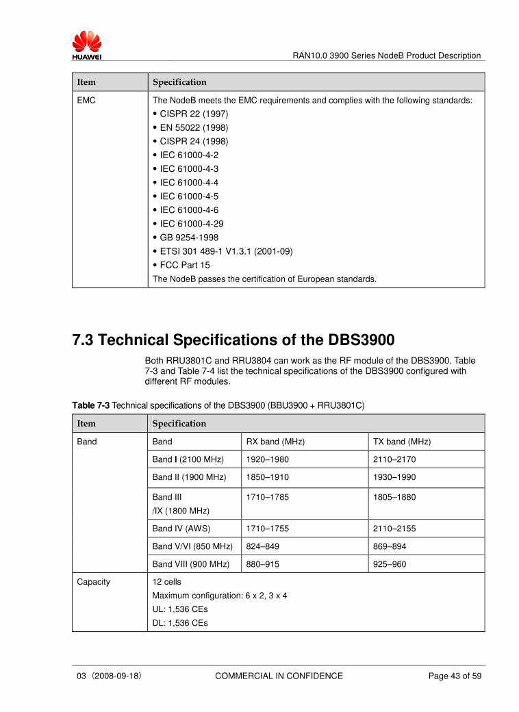
7.3 Technical Specifications of the DBS3900
Both RRU3801C and RRU3804 can work as the RF module of the DBS3900. Table 7-3 and Table 7-4 list the technical specifications of the DBS3900 configured with different RF modules.
Table 7-3 Technical specifications of the DBS3900 (BBU3900 + RRU3801C)
Item Specification
Band RX band (MHz) TX band (MHz)
Band I (2100 MHz) 1920–1980 2110–2170
Band II (1900 MHz) 1850–1910 1930–1990
Band III
/IX (1800 MHz)
1710–1785 1805–1880
Band IV (AWS) 1710–1755 2110–2155
Band V/VI (850 MHz) 824–849 869–894
Band
Band VIII (900 MHz) 880–915 925–960
Capacity 12 cells
Maximum configuration: 6 x 2, 3 x 4
UL: 1,536 CEs
DL: 1,536 CEs

RAN10.0 3900 Series NodeB Product Description
03 (2008-09-18) COMMERCIAL IN CONFIDENCE Page 43 of 59
Item Specification
Output power One RRU3801C supports two carriers with 40 W output power.
Band 1-way
receiver
sensitivity
(dBm)
2-way receiver
sensitivity
(dBm)
Remarks
–125.8 –128.6 As recommended in 3GPP
TS25.104, the receiver
sensitivity (full band) is
measured at the antenna
connector on condition that
the channel rate reaches
12.2 kbit/s and the BER is
within 0.001.
Band I (2100
MHz)
–126.5 –129.3 The receiver sensitivity
(median performance over
reception bandwidth) is
tested at the antenna
connector. The AMR
service should be at 12.2
kbit/s and the BER should
not exceed 0.0001.
–125.6 –128.4 As recommended in 3GPP
TS25.104, the receiver
sensitivity (full band) is
measured at the antenna
connector on condition that
the channel rate reaches
12.2 kbit/s and the BER is
within 0.001.
Receiver
sensitivity
Other bands
–126.3 –129.1 The receiver sensitivity
(median performance over
reception bandwidth) is
tested at the antenna
connector. The AMR
service should be at 12.2
kbit/s and the BER should
not exceed 0.0001.
Optical/ electrical A maximum of 48 E1s/T1s, 2 FE electrical ports, and 2 FE optical ports
Clock
synchronization
Clock on the Iub interface, GPS clock, OCXO free-run clock, and IP clock
Precision: 0.05 ppm
Specifications
(height x width x
depth)
BBU3900: 86 mm x 442 mm x 310 mm
RRU3801C: 480 mm x 365 mm x 145 mm (without rack and housing)
610 mm x 380 mm x 200 mm (with rack and housing)

RAN10.0 3900 Series NodeB Product Description
03 (2008-09-18) COMMERCIAL IN CONFIDENCE Page 43 of 59
Item Specification
Weight (kg) BBU3900: in full configuration: 11;
in 3 x 2 configuration: 7
RRU3801C: 20
Input power RRU3801C: –48 V DC, voltage range: –40 V DC to –60 V DC
220 V AC, voltage range: 150 V AC to 300 V AC
BBU3900: +24 V DC, voltage range: +21.6 V DC to +29 V DC
–48 V DC, voltage range: –38.4 V DC to –57 V DC
Power consumption Power backup duration in typical
power estimated on the basis of the
battery capacity
Configuration Typical power
consumption
(50% load)
Maximum
power
consumption
(W)
(100% load)
24 Ah 50 Ah 100 Ah
3 x 1 540 W 620 W 1.4
hours
3.6 hours 8.4 hours
Power
consumption
3 x 2 680 W 830 W 1.1
hours
2.9 hours 6.7 hours
Temperature BBU3900: –20°C to +55°C
RRU3801C:
–40°C to +50°C (with 1120 W/m2 solar radiation)
–40°C to +55°C (without solar radiation)
Relative humidity BBU3900: 5% RH to 85% RH
RRU3801C: 5% RH to 100% RH
Absolute
humidity
BBU3900: (1–25) g/m3
RRU3801C: (1–30) g/m3
Air pressure 70 kPa to 106 kPa
Protection
degree
BBU3900: IP20
RRU3801C: IP65
Storage ETSI EN300019-1-1 V2.1.4 (2003-04) class1.2 "Weatherprotected, not
temperature-controlled storage locations"
Transportation ETSI EN300019-1-2 V2.1.4 (2003-04) class 2.3 "Public transportation"
Anti-seismic
performance
IEC 60068-2-57 (1999-11) Environmental testing – Part 2-57: Tests – Test Ff: Vibration
– Time-history method.
YD5083-99: Interim Provisions for Test of Anti-seismic Performances of
Telecommunications Equipment (telecom industry standard in People's Republic of
China)

RAN10.0 3900 Series NodeB Product Description
03 (2008-09-18) COMMERCIAL IN CONFIDENCE Page 43 of 59
Item Specification
EMC The NodeB meets the EMC requirements and complies with the following standards:
� CISPR 22 (1997)
� EN 55022 (1998)
� CISPR 24 (1998)
� IEC 61000-4-2
� IEC 61000-4-3
� IEC 61000-4-4
� IEC 61000-4-5
� IEC 61000-4-6
� IEC 61000-4-29
� GB 9254-1998
� ETSI 301 489-1 V1.3.1 (2001-09)
� FCC Part 15
The NodeB passes the certification of European standards.
Table 7-4 Technical specifications of the DBS3900 (BBU3900 + RRU3804)
Item Specification
Band RX band
(MHz)
TX band (MHz)
Band I
(2100 MHz)
1920–1980 2110–2170
Band II
(1900 MHz)
1850–1910 1930–1990
Band V
/VI (850 MHz)
824–849 869–894
Band
Band IV (AWS) 1710–1755 2110–2155
Capacity 24 cells
Maximum configuration: 6 x 4, 3 x 8
UL: 1536 CEs
DL: 1536 CEs
Output power A single RRU3804 supports up to four carriers with a 60 W output power at the
antenna connector with four carriers.
� One-carrier configuration: 50 W per carrier
� Two-carrier configuration: 30 W per carrier (20 W per carrier in 1001 configuration)
� Three-carrier configuration: 20 W per carrier
� Four-carrier configuration: 15 W per carrier1

RAN10.0 3900 Series NodeB Product Description
03 (2008-09-18) COMMERCIAL IN CONFIDENCE Page 43 of 59
Item Specification
Band 1-way receiver
sensitivity
(dBm)
2-way receiver
sensitivity
(dBm)
Remarks
–125.8 –128.6 As recommended in 3GPP
TS25.104, the receiver
sensitivity (full band) is
measured at the antenna
connector on condition that
the channel rate reaches
12.2 kbit/s and the BER is
within 0.001.
Band I (2100
MHz)
–126.5 –129.3 The receiver sensitivity
(median performance over
reception bandwidth) is
tested at the antenna
connector. The AMR
service should be at 12.2
kbit/s and the BER should
not exceed 0.001.
–125.3 –128.1 As recommended in 3GPP
TS25.104, the receiver
sensitivity (full band) is
measured at the antenna
connector on condition that
the channel rate reaches
12.2 kbit/s and the BER is
within 0.001
Receiver
sensitivity
Band II
(1900 MHz)
Band V/VI (850
MHz)
–126.0 –128.8 The receiver sensitivity
(median performance over
reception bandwidth) is
tested at the antenna
connector. The AMR
service should be at 12.2
kbit/s and the BER should
not exceed 0.001.
Receiver
sensitivity
Other bands –125.6 –128.4 As recommended in 3GPP
TS25.104, the receiver
sensitivity (full band) is
measured at the antenna
connector on condition that
the channel rate reaches
12.2 kbit/s and the BER is
within 0.001.

RAN10.0 3900 Series NodeB Product Description
03 (2008-09-18) COMMERCIAL IN CONFIDENCE Page 43 of 59
Item Specification
–126.3 –129.1 The receiver sensitivity
(median performance over
reception bandwidth) is
tested at the antenna
connector. The AMR
service should be at 12.2
kbit/s and the BER should
not exceed 0.001.
Transmission port A maximum of 48 E1s/T1s, 2 FE electrical ports, and 2 FE optical ports
Clock
synchronization
Clock extracted from the Iub interface, GPS clock , OCXO free-run clock, and IP clock
Precision: 0.05 ppm
Specifications
(height x width x
depth)
BBU3900: 86 mm x 442 mm x 310 mm
RRU3804: 480 mm x 270 mm x 140 mm (without the housing and connectors)
485 mm x 285 mm x 170 mm (with the housing and connectors)
Weight (kg) BBU3900: full configuration: 11
typical configuration (1 PSU, 1 WBBP, 1 WMPT): 7
RRU3804: 15 (without the housing)
17 (without the housing)
Input voltage RRU3804: –48 V DC, voltage range: –36 V DC to –57 V DC
BBU3900: +24 V DC, voltage range: +21.6 V DC to +29 V DC
–48 V DC, voltage range: –38.4 V DC to –57 V DC
Power consumption Power backup duration in
typical power estimated on the
basis of the battery capacity
Configuration Typical power
consumption
(50% load)
Maximum
power
consumption
(100% load)
24 Ah 50 Ah 100 Ah
3 x 1 400 W 500 W 2.2
hours
5.5
hours
12.0 hours
Power
consumption
3 x 2 550 W 740 W 1.5
hours
3.7
hours
8.5 hours
Power
consumption
3 x 3 710 W 970 W 1.0
hours
2.8
hours
6.4 hours
Temperature BBU3900: –20°C to +55°C
RRU3804:
–40°C to +50°C (with 1120 W/m2 solar radiation)
–40°C to +55°C (without solar radiation)
Relative humidity BBU3900: 5% RH to 95% RH
RRU3804: 5% RH to 100% RH

RAN10.0 3900 Series NodeB Product Description
03 (2008-09-18) COMMERCIAL IN CONFIDENCE Page 43 of 59
Item Specification
Absolute humidity BBU3900: (1–25) g/m3
RRU3804: (1–30) g/m3
Air pressure 70 kPa to 106 kPa
Protection degree BBU3900: IP20
RRU3804: IP65
Storage ETSI EN300019-1-1 V2.1.4 (2003-04) class1.2 "Weatherprotected, not
temperature-controlled storage locations".
Transportation ETSI EN300019-1-2 V2.1.4 (2003-04) class 2.3 "Public transportation"
Anti-seismic
performance
IEC 60068-2-57 (1999-11) Environmental testing – Part 2-57: Tests – Test Ff:
Vibration – Time-history method.
YD5083-99: Interim Provisions for Test of Anti-seismic Performances of
Telecommunications Equipment (telecom industry standard in People's Republic of
China)
EMC The NodeB meets the EMC requirements and complies with the following standards:
� CISPR 22 (1997)
� EN 55022 (1998)
� CISPR 24 (1998)
� IEC 61000-4-2
� IEC 61000-4-3
� IEC 61000-4-4
� IEC 61000-4-5
� IEC 61000-4-6
� IEC 61000-4-29
� GB 9254-1998
� ETSI 301 489-1 V1.3.1 (2001-09)
� FCC Part 15
The NodeB passes the certification of European standards.
7.4 Technical specifications of the BTS3900C
Table 7-5 Technical specifications of the BTS3900C
Item Specification
Band RX band
(MHz)
TX band (MHz)
Band I (2100 MHz) 1920–1980 2110–2170
Band
Band II (1900 MHz) 1850–1910 1930–1990

RAN10.0 3900 Series NodeB Product Description
03 (2008-09-18) COMMERCIAL IN CONFIDENCE Page 43 of 59
Item Specification
Band V/VI (850 MHz) 824–849 869–894
Band IV (AWS) 1710–1755 2110–2155
Capacity 3 cells
Maximum configuration: 1 x 3
UL: 384 CEs
DL: 384 CEs
Output power The RRU3801C supports two carriers with a 40 W output power at the antenna
connector.
The RRU3804 supports four carriers with a 60 W output power at the antenna
connector.
Maximum output power = Maximum output power of the PA - Internal loss. The maximum output power is measured at the antenna connector of the base station.
The output power of the RRU3804 in different configurations is as follows:
� One-carrier configuration: 50 W per carrier
� Two-carrier configuration: 30 W per carrier (20 W per carrier in 1001 configuration)
� Three-carrier configuration: 20 W per carrier
� Four-carrier configuration: 15 W per carrier
Band 1-way
receiver
sensitivity
(dBm)
2-way
receiver
sensitivity
(dBm)
Remarks Receiver
sensitivity
Band I (2100
MHz)
–125.8 –128.6 As recommended in 3GPP
TS25.104, the receiver sensitivity
(full band) is measured at the
antenna connector on condition that
the channel rate reaches 12.2 kbit/s
and the BER is within 0.001.
Band I (2100
MHz)
–126.5 –129.3 The receiver sensitivity (median
performance over reception
bandwidth) is tested at the antenna
connector. The AMR service should
be at 12.2 kbit/s and the BER should
not exceed 0.0001.
Receiver
sensitivity
Other bands –125.6 –128.4 As recommended in 3GPP
TS25.104, the receiver sensitivity
(full band) is measured at the
antenna connector on condition that
the channel rate reaches 12.2 kbit/s
and the BER is within 0.001.
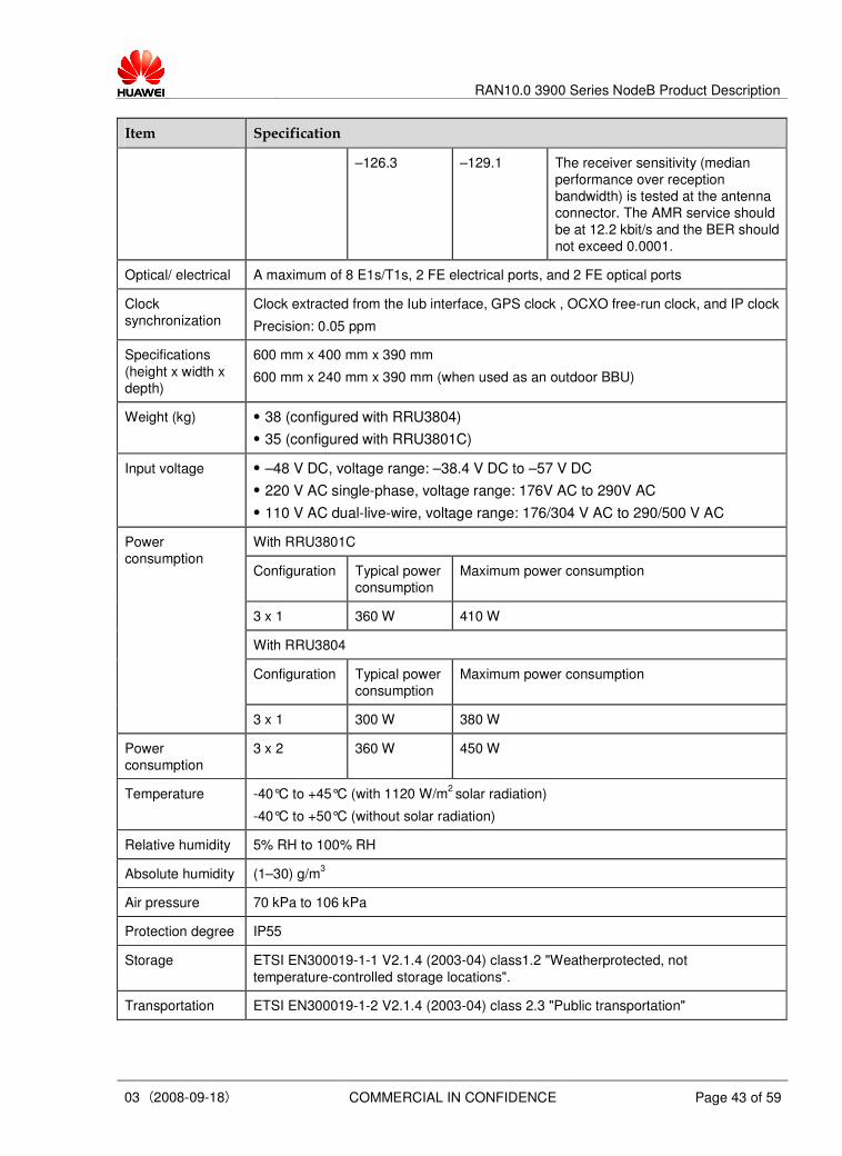
RAN10.0 3900 Series NodeB Product Description
03 (2008-09-18) COMMERCIAL IN CONFIDENCE Page 43 of 59
Item Specification
–126.3 –129.1 The receiver sensitivity (median
performance over reception
bandwidth) is tested at the antenna
connector. The AMR service should
be at 12.2 kbit/s and the BER should
not exceed 0.0001.
Optical/ electrical A maximum of 8 E1s/T1s, 2 FE electrical ports, and 2 FE optical ports
Clock
synchronization
Clock extracted from the Iub interface, GPS clock , OCXO free-run clock, and IP clock
Precision: 0.05 ppm
Specifications
(height x width x
depth)
600 mm x 400 mm x 390 mm
600 mm x 240 mm x 390 mm (when used as an outdoor BBU)
Weight (kg) � 38 (configured with RRU3804)
� 35 (configured with RRU3801C)
Input voltage � –48 V DC, voltage range: –38.4 V DC to –57 V DC
� 220 V AC single-phase, voltage range: 176V AC to 290V AC
� 110 V AC dual-live-wire, voltage range: 176/304 V AC to 290/500 V AC
With RRU3801C
Configuration Typical power
consumption
Maximum power consumption
3 x 1 360 W 410 W
With RRU3804
Configuration Typical power
consumption
Maximum power consumption
Power
consumption
3 x 1 300 W 380 W
Power
consumption
3 x 2 360 W 450 W
Temperature -40°C to +45°C (with 1120 W/m2 solar radiation)
-40°C to +50°C (without solar radiation)
Relative humidity 5% RH to 100% RH
Absolute humidity (1–30) g/m3
Air pressure 70 kPa to 106 kPa
Protection degree IP55
Storage ETSI EN300019-1-1 V2.1.4 (2003-04) class1.2 "Weatherprotected, not
temperature-controlled storage locations".
Transportation ETSI EN300019-1-2 V2.1.4 (2003-04) class 2.3 "Public transportation"

RAN10.0 3900 Series NodeB Product Description
03 (2008-09-18) COMMERCIAL IN CONFIDENCE Page 43 of 59
Item Specification
Anti-seismic
performance
IEC 60068-2-57 (1999-11) Environmental testing – Part 2-57: Tests – Test Ff:
Vibration – Time-history method.
YD5083-99: Interim Provisions for Test of Anti-seismic Performances of
Telecommunications Equipment (telecom industry standard in People's Republic of
China)
EMC The NodeB meets the EMC requirements and complies with the following standards:
� CISPR 22 (1997)
� EN 55022 (1998)
� CISPR 24 (1998)
� IEC 61000-4-2
� IEC 61000-4-3
� IEC 61000-4-4
� IEC 61000-4-5
� IEC 61000-4-6
� IEC 61000-4-29
� GB 9254-1998
� ETSI 301 489-1 V1.3.1 (2001-09)
� FCC Part 15
The NodeB passes the certification of European standards.
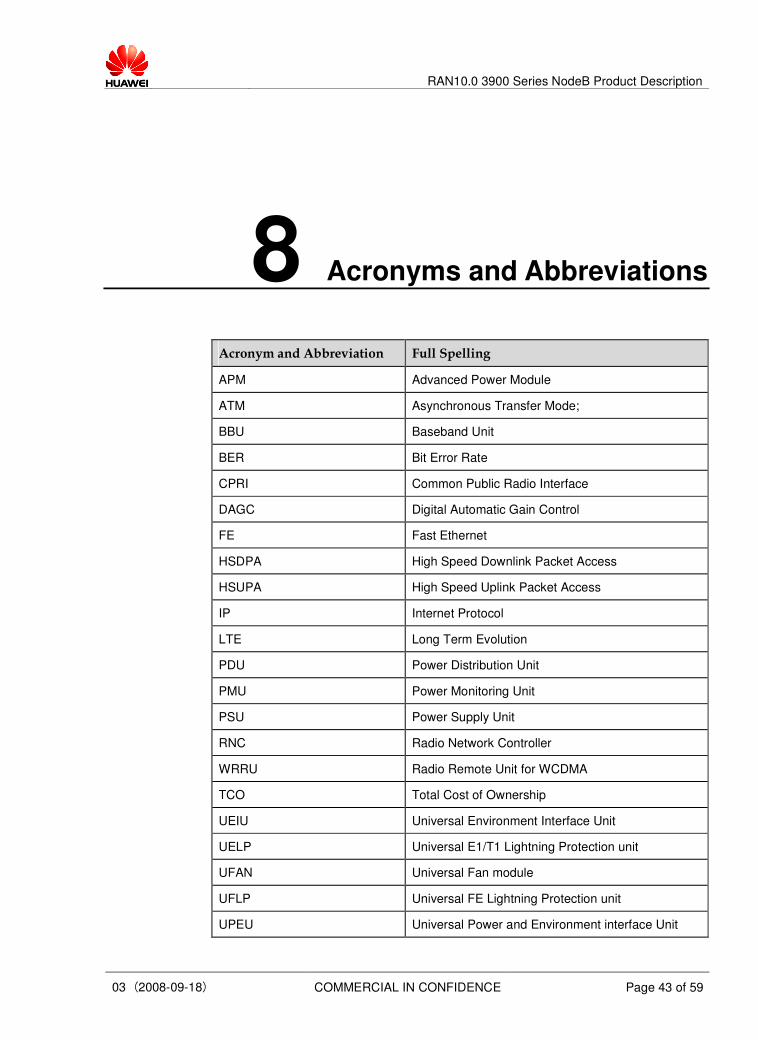
RAN10.0 3900 Series NodeB Product Description
03 (2008-09-18) COMMERCIAL IN CONFIDENCE Page 43 of 59
8 Acronyms and Abbreviations
Acronym and Abbreviation Full Spelling
APM Advanced Power Module
ATM Asynchronous Transfer Mode;
BBU Baseband Unit
BER Bit Error Rate
CPRI Common Public Radio Interface
DAGC Digital Automatic Gain Control
FE Fast Ethernet
HSDPA High Speed Downlink Packet Access
HSUPA High Speed Uplink Packet Access
IP Internet Protocol
LTE Long Term Evolution
PDU Power Distribution Unit
PMU Power Monitoring Unit
PSU Power Supply Unit
RNC Radio Network Controller
WRRU Radio Remote Unit for WCDMA
TCO Total Cost of Ownership
UEIU Universal Environment Interface Unit
UELP Universal E1/T1 Lightning Protection unit
UFAN Universal Fan module
UFLP Universal FE Lightning Protection unit
UPEU Universal Power and Environment interface Unit
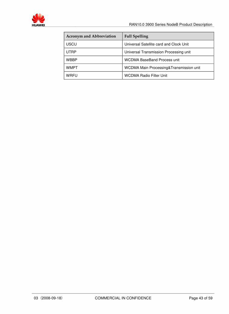
RAN10.0 3900 Series NodeB Product Description
03 (2008-09-18) COMMERCIAL IN CONFIDENCE Page 43 of 59
Acronym and Abbreviation Full Spelling
USCU Universal Satellite card and Clock Unit
UTRP Universal Transmission Processing unit
WBBP WCDMA BaseBand Process unit
WMPT WCDMA Main Processing&Transmission unit
WRFU WCDMA Radio Filter Unit
Recommended