8/10/2019 7010-0980 - GRX Utility RM.pdf
http://slidepdf.com/reader/full/7010-0980-grx-utility-rmpdf 1/80
GRX Utility
GRX Utility

8/10/2019 7010-0980 - GRX Utility RM.pdf
http://slidepdf.com/reader/full/7010-0980-grx-utility-rmpdf 2/80
8/10/2019 7010-0980 - GRX Utility RM.pdf
http://slidepdf.com/reader/full/7010-0980-grx-utility-rmpdf 3/80
GRX UtilityReference Manual
Part Number 7010-0980
Rev A
December, 2009
The information contained herein may not be used, accessed, copied, stored,
displayed, sold, modified, published, or distributed, or otherwise reproduced.

8/10/2019 7010-0980 - GRX Utility RM.pdf
http://slidepdf.com/reader/full/7010-0980-grx-utility-rmpdf 4/80
ECO#3779
8/10/2019 7010-0980 - GRX Utility RM.pdf
http://slidepdf.com/reader/full/7010-0980-grx-utility-rmpdf 5/80
P/N 7010-0980
TOC
i
Table of ContentsPreface .................................................................... v
Terms and Conditions .......................................................... v
Manual Conventions ............................................................ viii
Chapter 1Getting Started ....................................................... 1-1
Starting GRX Utility ............................................................ 1-1
Main Window ...................................................................... 1-2
The Menu Bar ............................................................... 1-2
The Tool Bar ................................................................. 1-3
The Status Bar ............................................................... 1-3
Application Modes ............................................................... 1-3About GRX Utility .............................................................. 1-4
Setup .................................................................................... 1-6
General Settings ............................................................ 1-7
Modems Detection ........................................................ 1-7
Exiting the Program ............................................................. 1-8
Chapter 2
Connection .............................................................. 2-1Connection Parameters ........................................................ 2-2
Detecting Hardware ............................................................. 2-4
Disconnecting Auto Detection ............................................. 2-5
Chapter 3
Simple Terminal ...................................................... 3-1Terminal ............................................................................... 3-2
Firmware .............................................................................. 3-5
Chapter 4
Receiver Managing ................................................. 4-1Terminal ............................................................................... 4-3
8/10/2019 7010-0980 - GRX Utility RM.pdf
http://slidepdf.com/reader/full/7010-0980-grx-utility-rmpdf 6/80
Table of Contents
GRX Utility Reference Manualii
Information .......................................................................... 4-3
Options ................................................................................ 4-4
Upload OAF .................................................................. 4-5
Firmware ....................................................................... 4-7Tools .................................................................................... 4-12
Receiver Settings ................................................................. 4-13
Tracking ........................................................................ 4-14
Positioning .................................................................... 4-17
Ports .............................................................................. 4-20
Power ............................................................................ 4-21
Auto Seed ...................................................................... 4-22Point List ................................................................ 4-23
Add New Point ....................................................... 4-25
Volume Control ............................................................ 4-26
Bluetooth ....................................................................... 4-26
Status ................................................................................... 4-27
Position ......................................................................... 4-27
Data Link ...................................................................... 4-29
SVs List ........................................................................ 4-29Sky Plot ......................................................................... 4-32
Scatter Plot .................................................................... 4-33
Position in Time ............................................................ 4-34
Logging ......................................................................... 4-35
Logging Messages .................................................. 4-36
Site Configuration .................................................. 4-39
File Explorer ........................................................................ 4-40
Files ............................................................................... 4-40
Logs .............................................................................. 4-43
Chapter 5
Modem Managing ................................................... 5-1Terminal .............................................................................. 5-2
Settings ................................................................................ 5-2
General Information ...................................................... 5-2Modem Settings ............................................................ 5-3
Modem Functions ......................................................... 5-3

8/10/2019 7010-0980 - GRX Utility RM.pdf
http://slidepdf.com/reader/full/7010-0980-grx-utility-rmpdf 7/80
P/N 7010-0980
Preface
v
PrefaceThank you for purchasing this Sokkia product. The materials
available in this Manual (the “Manual”) have been prepared by
Sokkia for owners of Sokkia products, and are designed to assist
owners with the use of the receiver and its use is subject to these
terms and conditions (the “Terms and Conditions”).
Terms and ConditionsUSE This product is designed to be used by a professional. The user
should have a good knowledge of the safe use of the product and
implement the types of safety procedures recommended by the local
government protection agency for both private use and commercial
job sites.
COPYRIGHT All information contained in this Manual is the
intellectual property of, and copyrighted material of Sokkia. All
rights are reserved. Do not use, access, copy, store, display, create
derivative works of, sell, modify, publish, distribute, or allow any
third party access to, any graphics, content, information or data in this
Manual without Sokkia’s express written consent and may only use
such information for the care and operation of your receiver. The
information and data in this Manual are a valuable asset of Sokkia
and are developed by the expenditure of considerable work, time andmoney, and are the result of original selection, coordination and
arrangement by Sokkia.
NOTICE Please read these Terms and Conditions carefully.

8/10/2019 7010-0980 - GRX Utility RM.pdf
http://slidepdf.com/reader/full/7010-0980-grx-utility-rmpdf 8/80
Preface
GRX Utility Reference Manualvi
TRADEMARKS GRX1™, Spectrum Survey Office™, Spectrum
Link™, Spectrum Survey Field™, SHC2500™, and GRX Utility™
are trademarks or registered trademarks of Sokkia. Windows® is a
registered trademark of Microsoft Corporation. The Bluetooth® wordmark and logos are owned by Bluetooth SIG, Inc. and any use of such
marks by Sokkia is used under license. Other product and company
names mentioned herein may be trademarks of their respective
owners.
DISCLAIMER OF WARRANTY EXCEPT FOR ANY
WARRANTIES IN AN APPENDIX OR A WARRANTY CARD
ACCOMPANYING THE PRODUCT, THIS MANUAL AND THERECEIVER ARE PROVIDED “AS-IS.” THERE ARE NO OTHER
WARRANTIES. SOKKIA DISCLAIMS ANY IMPLIED
WARRANTY OF MERCHANTABILITY OR FITNESS FOR ANY
PARTICULAR USE OR PURPOSE. SOKKIA AND ITS
DISTRIBUTORS SHALL NOT BE LIABLE FOR TECHNICAL OR
EDITORIAL ERRORS OR OMISSIONS CONTAINED HEREIN;
NOR FOR INCIDENTAL OR CONSEQUENTIAL DAMAGES
RESULTING FROM THE FURNISHING, PERFORMANCE OR
USE OF THIS MATERIAL OR THE RECEIVER. SUCH
DISCLAIMED DAMAGES INCLUDE BUT ARE NOT LIMITED
TO LOSS OF TIME, LOSS OR DESTRUCTION OF DATA, LOSS
OF PROFIT, SAVINGS OR REVENUE, OR LOSS OF THE
PRODUCT’S USE. IN ADDITION SOKKIA IS NOT
RESPONSIBLE OR LIABLE FOR DAMAGES OR COSTS
INCURRED IN CONNECTION WITH OBTAININGSUBSTITUTE PRODUCTS OR SOFTWARE, CLAIMS BY
OTHERS, INCONVENIENCE, OR ANY OTHER COSTS. IN ANY
EVENT, SOKKIA SHALL HAVE NO LIABILITY FOR
DAMAGES OR OTHERWISE TO YOU OR ANY OTHER
PERSON OR ENTITY IN EXCESS OF THE PURCHASE PRICE
FOR THE RECEIVER.
LICENSE AGREEMENT Use of any computer programs or softwaresupplied by Sokkia or downloaded from a Sokkia website (the
“Software”) in connection with the receiver constitutes acceptance of
these Terms and Conditions in this Manual and an agreement to abide
by these Terms and Conditions. The user is granted a personal, non-
8/10/2019 7010-0980 - GRX Utility RM.pdf
http://slidepdf.com/reader/full/7010-0980-grx-utility-rmpdf 9/80
Terms and Conditions
P/N 7010-0980 vii
exclusive, non-transferable license to use such Software under the
terms stated herein and in any case only with a single receiver or
single computer. You may not assign or transfer the Software or this
license without the express written consent of Sokkia. This license iseffective until terminated. You may terminate the license at any time
by destroying the Software and Manual. Sokkia may terminate the
license if you fail to comply with any of the Terms or Conditions.
You agree to destroy the Software and manual upon termination of
your use of the receiver. All ownership, copyright and other
intellectual property rights in and to the Software belong to Sokkia. If
these license terms are not acceptable, return any unused software andmanual.
CONFIDENTIALITY This Manual, its contents and the Software
(collectively, the “Confidential Information”) are the confidential and
proprietary information of Sokkia. You agree to treat Sokkia’s
Confidential Information with a degree of care no less stringent that the
degree of care you would use in safeguarding your own most valuable
trade secrets. Nothing in this paragraph shall restrict you fromdisclosing Confidential Information to your employees as may be
necessary or appropriate to operate or care for the receiver. Such
employees must also keep the Confidentiality Information confidential.
In the event you become legally compelled to disclose any of the
Confidential Information, you shall give Sokkia immediate notice so
that it may seek a protective order or other appropriate remedy.
WEBSITE; OTHER STATEMENTS No statement contained at the
Sokkia website (or any other website) or in any other advertisements
or Sokkia literature or made by an employee or independent
contractor of Sokkia modifies these Terms and Conditions (including
the Software license, warranty and limitation of liability).
SAFETY Improper use of the receiver can lead to injury to persons or
property and/or malfunction of the product. The receiver should only
be repaired by authorized Sokkia warranty service centers. Users
should review and heed the safety warnings in an Appendix.
MISCELLANEOUS The above Terms and Conditions may be
amended, modified, superseded, or canceled, at any time by Sokkia.
The above Terms and Conditions will be governed by, and construed
8/10/2019 7010-0980 - GRX Utility RM.pdf
http://slidepdf.com/reader/full/7010-0980-grx-utility-rmpdf 10/80
Preface
GRX Utility Reference Manualviii
in accordance with, the laws of the State of California, without
reference to conflict of laws.
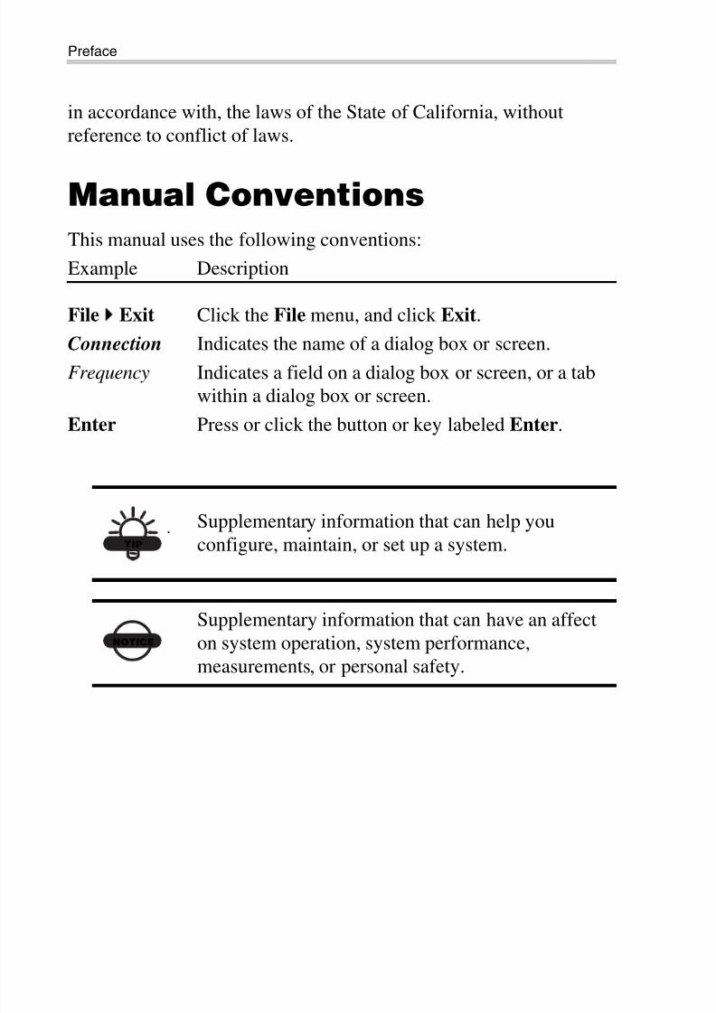
Manual Conventions
This manual uses the following conventions:
Example Description
File
Exit Click the File menu, and click Exit.
Connection Indicates the name of a dialog box or screen.
Frequency Indicates a field on a dialog box or screen, or a tab
within a dialog box or screen.
Enter Press or click the button or key labeled Enter.
TIP
Supplementary information that can help you
configure, maintain, or set up a system.
NOTICE
Supplementary information that can have an affect
on system operation, system performance,
measurements, or personal safety.
8/10/2019 7010-0980 - GRX Utility RM.pdf
http://slidepdf.com/reader/full/7010-0980-grx-utility-rmpdf 11/80
P/N 7010-0980
Chapter 1
1-1
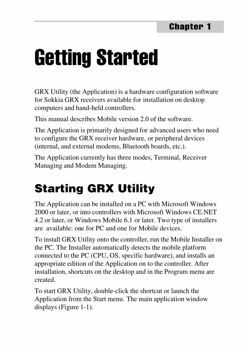
Getting StartedGRX Utility (the Application) is a hardware configuration software
for Sokkia GRX receivers available for installation on desktop
computers and hand-held controllers.
This manual describes Mobile version 2.0 of the software.
The Application is primarily designed for advanced users who need
to configure the GRX receiver hardware, or peripheral devices
(internal, and external modems, Bluetooth boards, etc.).
The Application currently has three modes, Terminal, Receiver
Managing and Modem Managing.
Starting GRX Utility
The Application can be installed on a PC with Microsoft Windows
2000 or later, or into controllers with Microsoft Windows CE.NET
4.2 or later, or Windows Mobile 6.1 or later. Two type of installers
are available: one for PC and one for Mobile devices.
To install GRX Utility onto the controller, run the Mobile Installer on
the PC. The Installer automatically detects the mobile platformconnected to the PC (CPU, OS, specific hardware), and installs an
appropriate edition of the Application on to the controller. After
installation, shortcuts on the desktop and in the Program menu are
created.
To start GRX Utility, double-click the shortcut or launch the
Application from the Start menu. The main application window
displays (Figure 1-1).
8/10/2019 7010-0980 - GRX Utility RM.pdf
http://slidepdf.com/reader/full/7010-0980-grx-utility-rmpdf 12/80
Getting Started
GRX Utility Reference Manual1-2
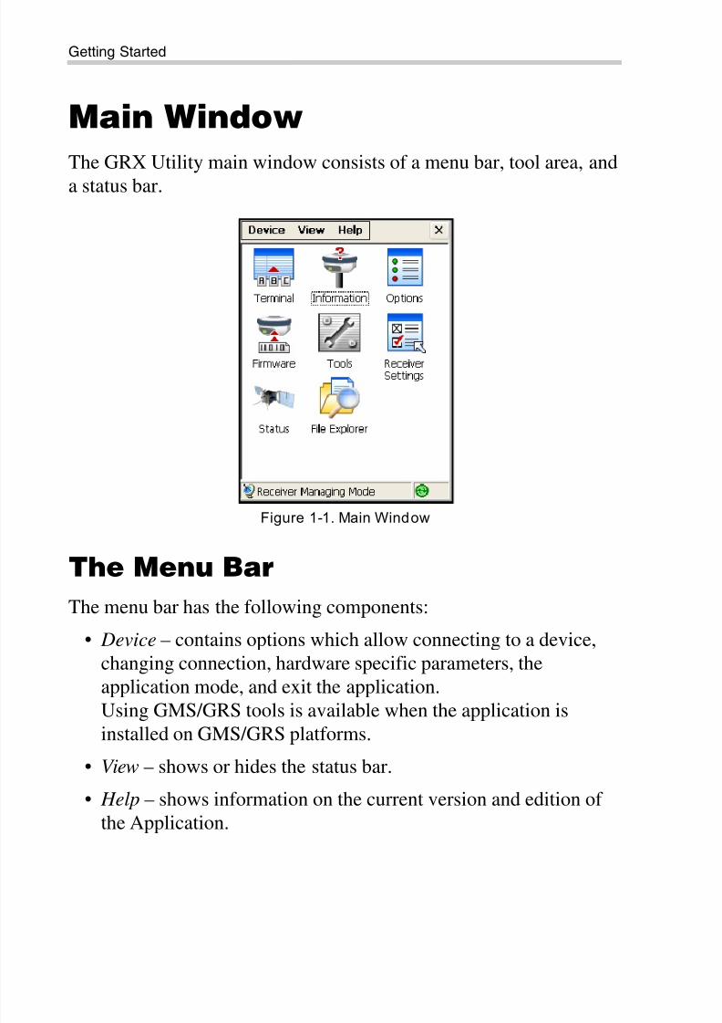
Main Window
The GRX Utility main window consists of a menu bar, tool area, and
a status bar.
Figure 1-1. Main Window
The Menu Bar
The menu bar has the following components:
• Device – contains options which allow connecting to a device,
changing connection, hardware specific parameters, the
application mode, and exit the application.
Using GMS/GRS tools is available when the application isinstalled on GMS/GRS platforms.
• View – shows or hides the status bar.
• Help – shows information on the current version and edition of
the Application.
8/10/2019 7010-0980 - GRX Utility RM.pdf
http://slidepdf.com/reader/full/7010-0980-grx-utility-rmpdf 13/80
Application Modes
P/N 7010-0980 1-3
The Tool Bar
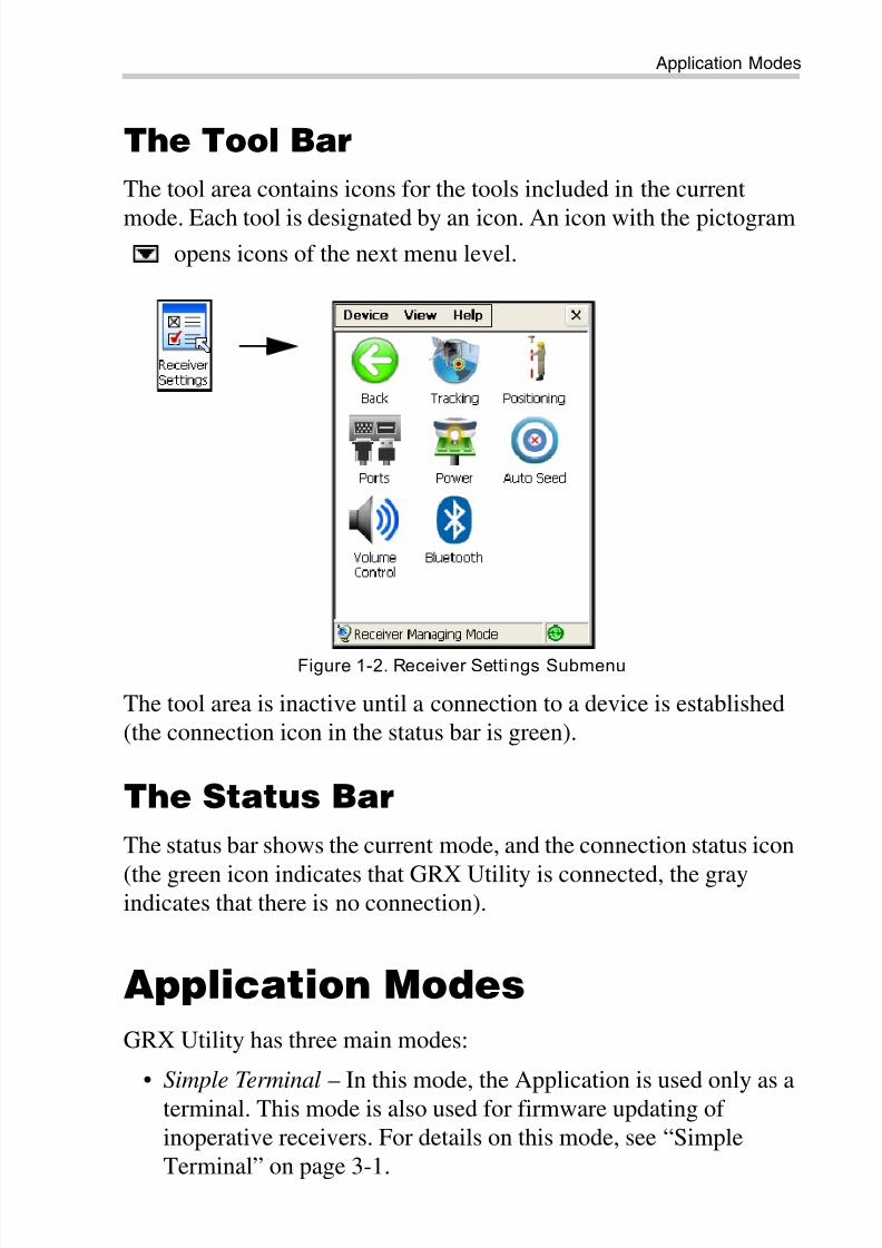
The tool area contains icons for the tools included in the current
mode. Each tool is designated by an icon. An icon with the pictogramopens icons of the next menu level.
Figure 1-2. Receiver Settings Submenu
The tool area is inactive until a connection to a device is established
(the connection icon in the status bar is green).
The Status Bar
The status bar shows the current mode, and the connection status icon
(the green icon indicates that GRX Utility is connected, the grayindicates that there is no connection).
Application Modes
GRX Utility has three main modes:
• Simple Terminal – In this mode, the Application is used only as a
terminal. This mode is also used for firmware updating of
inoperative receivers. For details on this mode, see “Simple
Terminal” on page 3-1.
8/10/2019 7010-0980 - GRX Utility RM.pdf
http://slidepdf.com/reader/full/7010-0980-grx-utility-rmpdf 14/80
Getting Started
GRX Utility Reference Manual1-4
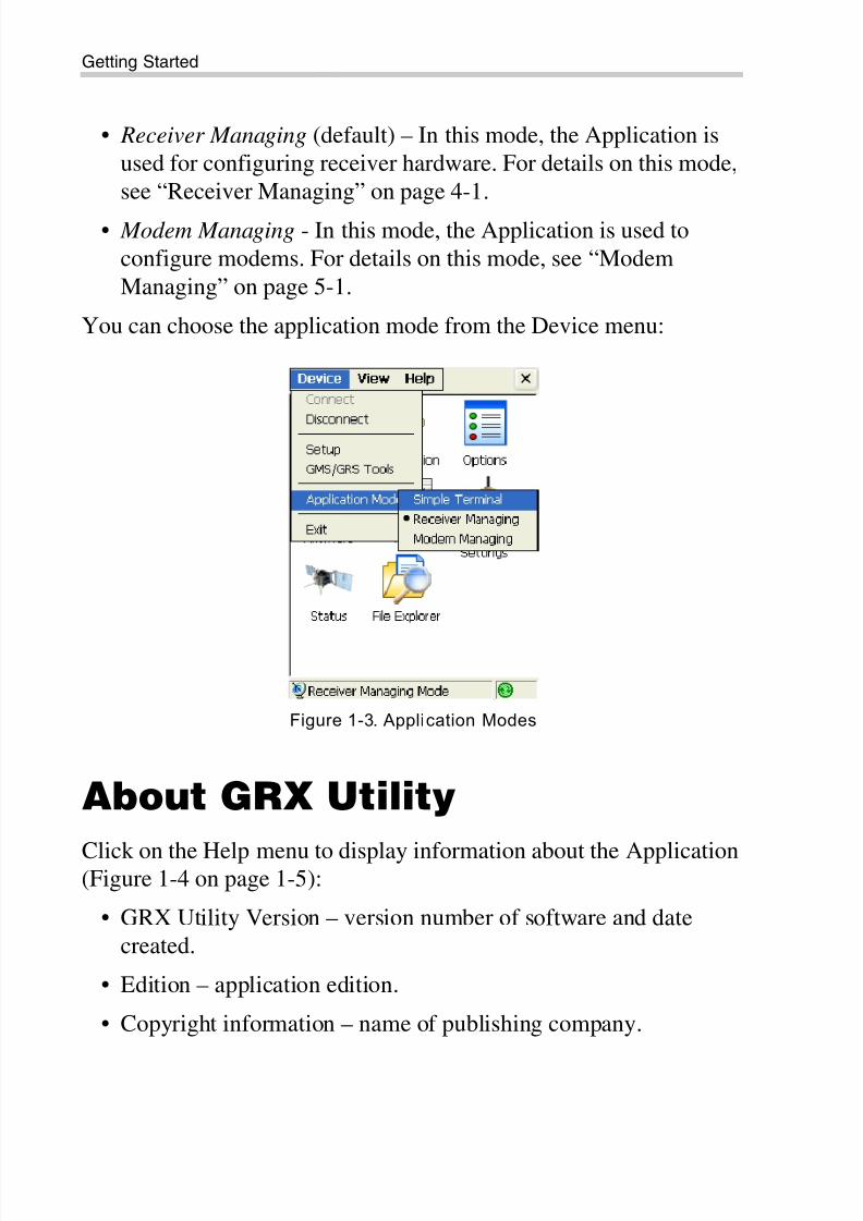
• Receiver Managing (default) – In this mode, the Application is
used for configuring receiver hardware. For details on this mode,
see “Receiver Managing” on page 4-1.
• Modem Managing - In this mode, the Application is used to
configure modems. For details on this mode, see “Modem
Managing” on page 5-1.
You can choose the application mode from the Device menu:
Figure 1-3. Application Modes
About GRX Utility
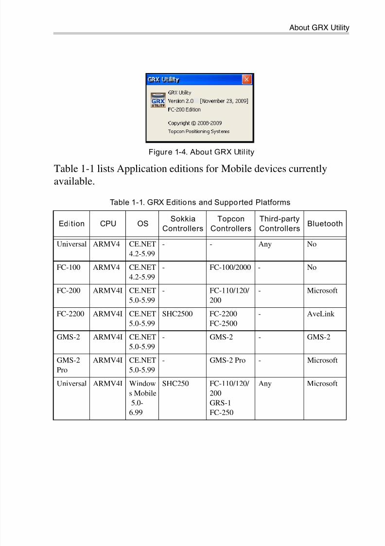
Click on the Help menu to display information about the Application(Figure 1-4 on page 1-5):
• GRX Utility Version – version number of software and date
created.
• Edition – application edition.
• Copyright information – name of publishing company.
8/10/2019 7010-0980 - GRX Utility RM.pdf
http://slidepdf.com/reader/full/7010-0980-grx-utility-rmpdf 15/80
About GRX Utility
P/N 7010-0980 1-5
Figure 1-4. About GRX Util ity
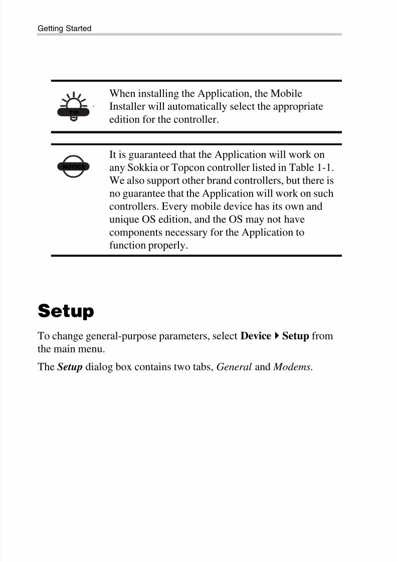
Table 1-1 lists Application editions for Mobile devices currently
available.
Table 1-1. GRX Editions and Supported Platforms
Edition CPU OSSokkia
Controllers
Topcon
Controllers
Third-party
ControllersBluetooth
Universal ARMV4 CE.NET
4.2-5.99
- - Any No
FC-100 ARMV4 CE.NET
4.2-5.99
- FC-100/2000 - No
FC-200 ARMV4I CE.NET
5.0-5.99
- FC-110/120/
200
- Microsoft
FC-2200 ARMV4I CE.NET
5.0-5.99
SHC2500 FC-2200
FC-2500
- AveLink
GMS-2 ARMV4I CE.NET
5.0-5.99
- GMS-2 - GMS-2
GMS-2
Pro
ARMV4I CE.NET
5.0-5.99
- GMS-2 Pro - Microsoft
Universal ARMV4I Windows Mobile
5.0-
6.99
SHC250 FC-110/120/ 200
GRS-1
FC-250
Any Microsoft
8/10/2019 7010-0980 - GRX Utility RM.pdf
http://slidepdf.com/reader/full/7010-0980-grx-utility-rmpdf 16/80
Getting Started
GRX Utility Reference Manual1-6
Setup
To change general-purpose parameters, select Device
Setup from
the main menu.
The Setup dialog box contains two tabs, General and Modems.
TIP
When installing the Application, the MobileInstaller will automatically select the appropriate
edition for the controller.
NOTICE
It is guaranteed that the Application will work on
any Sokkia or Topcon controller listed in Table 1-1.
We also support other brand controllers, but there is
no guarantee that the Application will work on suchcontrollers. Every mobile device has its own and
unique OS edition, and the OS may not have
components necessary for the Application to
function properly.
8/10/2019 7010-0980 - GRX Utility RM.pdf
http://slidepdf.com/reader/full/7010-0980-grx-utility-rmpdf 17/80
Setup
P/N 7010-0980 1-7
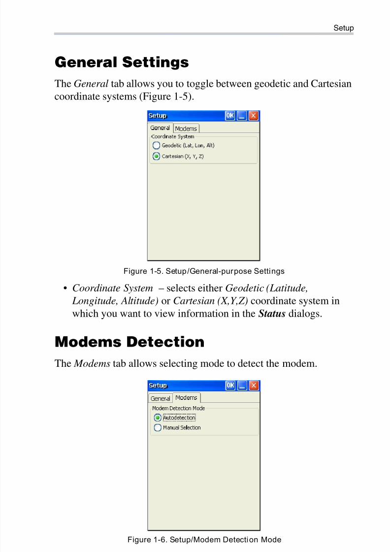
General Settings
The General tab allows you to toggle between geodetic and Cartesian
coordinate systems (Figure 1-5).
Figure 1-5. Setup/General-purpose Settings
• Coordinate System – selects either Geodetic (Latitude, Longitude, Altitude) or Cartesian (X,Y,Z) coordinate system in
which you want to view information in the Status dialogs.
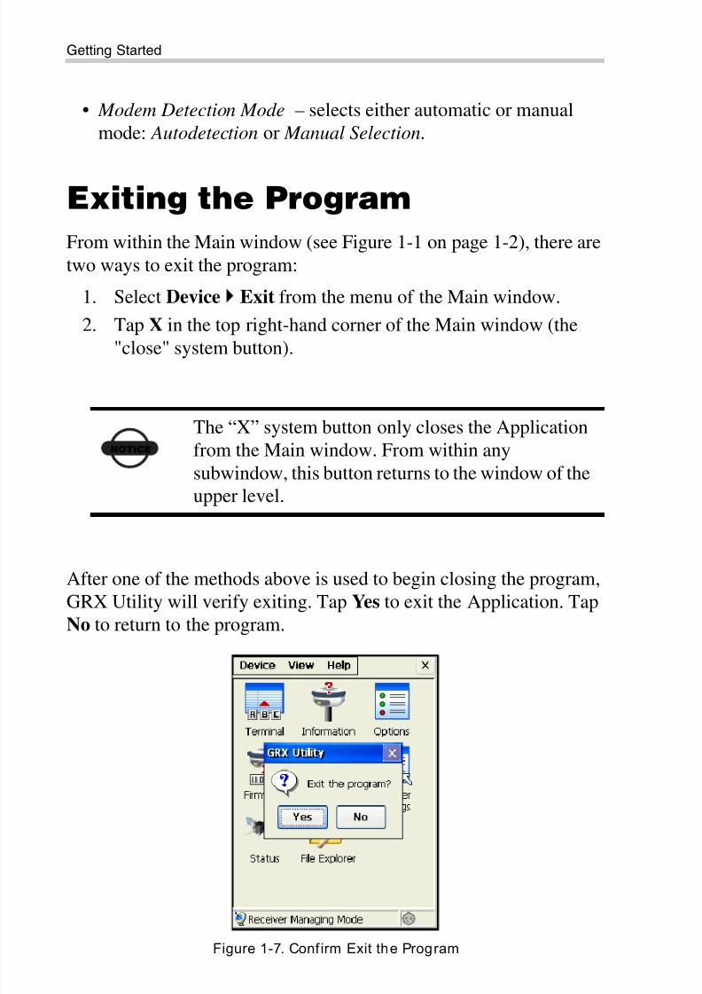
Modems Detection
The Modems tab allows selecting mode to detect the modem.
Figure 1-6. Setup/Modem Detection Mode
8/10/2019 7010-0980 - GRX Utility RM.pdf
http://slidepdf.com/reader/full/7010-0980-grx-utility-rmpdf 18/80
Getting Started
GRX Utility Reference Manual1-8
• Modem Detection Mode – selects either automatic or manual
mode: Autodetection or Manual Selection.
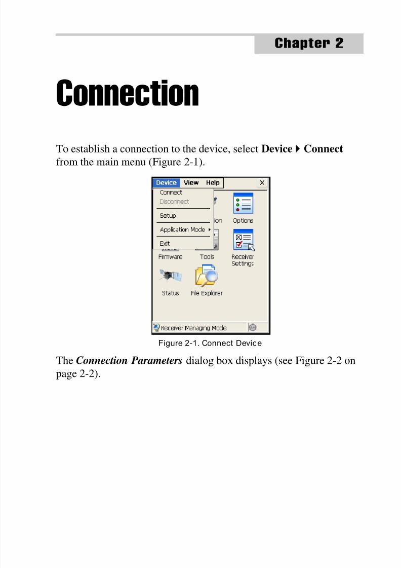
Exiting the Program
From within the Main window (see Figure 1-1 on page 1-2), there are
two ways to exit the program:
1. Select Device Exit from the menu of the Main window.
2. Tap X in the top right-hand corner of the Main window (the
"close" system button).
After one of the methods above is used to begin closing the program,
GRX Utility will verify exiting. Tap Yes to exit the Application. Tap
No to return to the program.
Figure 1-7. Confirm Exit the Program
NOTICE
The “X” system button only closes the Application
from the Main window. From within any
subwindow, this button returns to the window of the
upper level.
8/10/2019 7010-0980 - GRX Utility RM.pdf
http://slidepdf.com/reader/full/7010-0980-grx-utility-rmpdf 19/80
P/N 7010-0980
Chapter 2
2-1
ConnectionTo establish a connection to the device, select Device
Connect
from the main menu (Figure 2-1).
Figure 2-1. Connect Device
The Connection Parameters dialog box displays (see Figure 2-2 on
page 2-2).
8/10/2019 7010-0980 - GRX Utility RM.pdf
http://slidepdf.com/reader/full/7010-0980-grx-utility-rmpdf 20/80
Connection
GRX Utility Reference Manual2-2
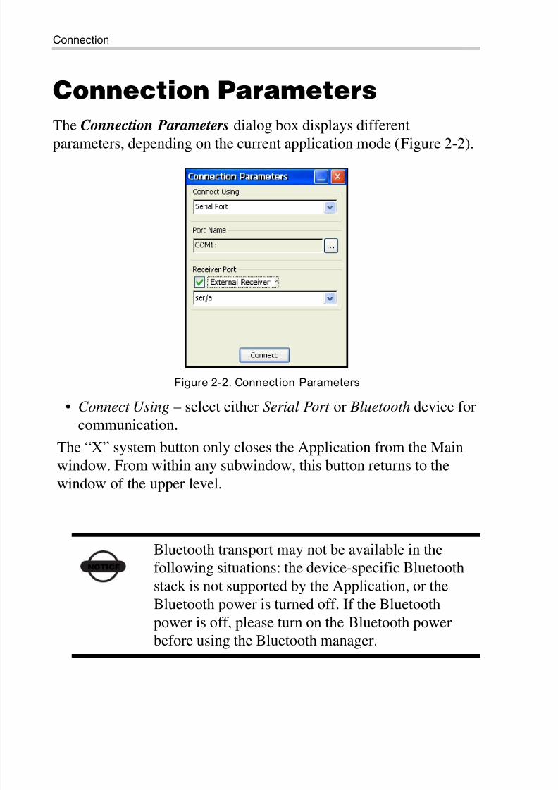
Connection Parameters
The Connection Parameters dialog box displays different
parameters, depending on the current application mode (Figure 2-2).
Figure 2-2. Connect ion Parameters
• Connect Using – select either Serial Port or Bluetooth device for
communication.
The “X” system button only closes the Application from the Main
window. From within any subwindow, this button returns to the
window of the upper level.
NOTICEBluetooth transport may not be available in thefollowing situations: the device-specific Bluetooth
stack is not supported by the Application, or the
Bluetooth power is turned off. If the Bluetooth
power is off, please turn on the Bluetooth power
before using the Bluetooth manager.
8/10/2019 7010-0980 - GRX Utility RM.pdf
http://slidepdf.com/reader/full/7010-0980-grx-utility-rmpdf 21/80
Connection Parameters
P/N 7010-0980 2-3
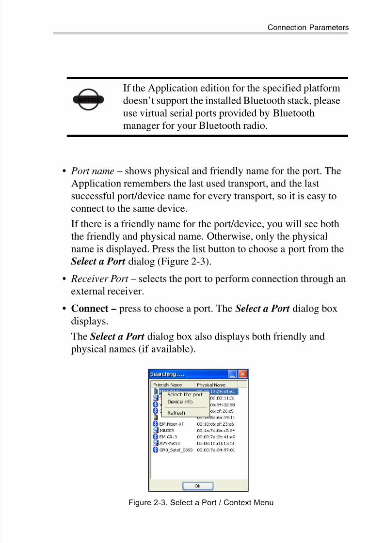
• Port name – shows physical and friendly name for the port. The
Application remembers the last used transport, and the last
successful port/device name for every transport, so it is easy to
connect to the same device.
If there is a friendly name for the port/device, you will see both
the friendly and physical name. Otherwise, only the physical
name is displayed. Press the list button to choose a port from the
Select a Port dialog (Figure 2-3).
• Receiver Port – selects the port to perform connection through an
external receiver.
• Connect – press to choose a port. The Select a Port dialog box
displays.
The Select a Port dialog box also displays both friendly and
physical names (if available).
Figure 2-3. Select a Port / Context Menu
NOTICE
If the Application edition for the specified platform
doesn’t support the installed Bluetooth stack, please
use virtual serial ports provided by Bluetooth
manager for your Bluetooth radio.
8/10/2019 7010-0980 - GRX Utility RM.pdf
http://slidepdf.com/reader/full/7010-0980-grx-utility-rmpdf 22/80
Connection
GRX Utility Reference Manual2-4
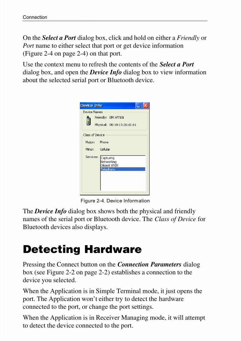
On the Select a Port dialog box, click and hold on either a Friendly or
Port name to either select that port or get device information
(Figure 2-4 on page 2-4) on that port.
Use the context menu to refresh the contents of the Select a Port
dialog box, and open the Device Info dialog box to view information
about the selected serial port or Bluetooth device.
Figure 2-4. Device Information
The Device Info dialog box shows both the physical and friendly
names of the serial port or Bluetooth device. The Class of Device for
Bluetooth devices also displays.
Detecting Hardware
Pressing the Connect button on the Connection Parameters dialog
box (see Figure 2-2 on page 2-2) establishes a connection to the
device you selected.
When the Application is in Simple Terminal mode, it just opens the
port. The Application won’t either try to detect the hardwareconnected to the port, or change the port settings.
When the Application is in Receiver Managing mode, it will attempt
to detect the device connected to the port.
8/10/2019 7010-0980 - GRX Utility RM.pdf
http://slidepdf.com/reader/full/7010-0980-grx-utility-rmpdf 23/80
Disconnecting Auto Detection
P/N 7010-0980 2-5
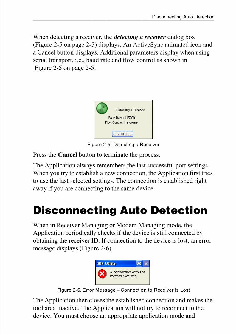
When detecting a receiver, the detecting a receiver dialog box
(Figure 2-5 on page 2-5) displays. An ActiveSync animated icon and
a Cancel button displays. Additional parameters display when using
serial transport, i.e., baud rate and flow control as shown in
Figure 2-5 on page 2-5.
Figure 2-5. Detecting a Receiver
Press the Cancel button to terminate the process.
The Application always remembers the last successful port settings.
When you try to establish a new connection, the Application first triesto use the last selected settings. The connection is established right
away if you are connecting to the same device.
Disconnecting Auto Detection
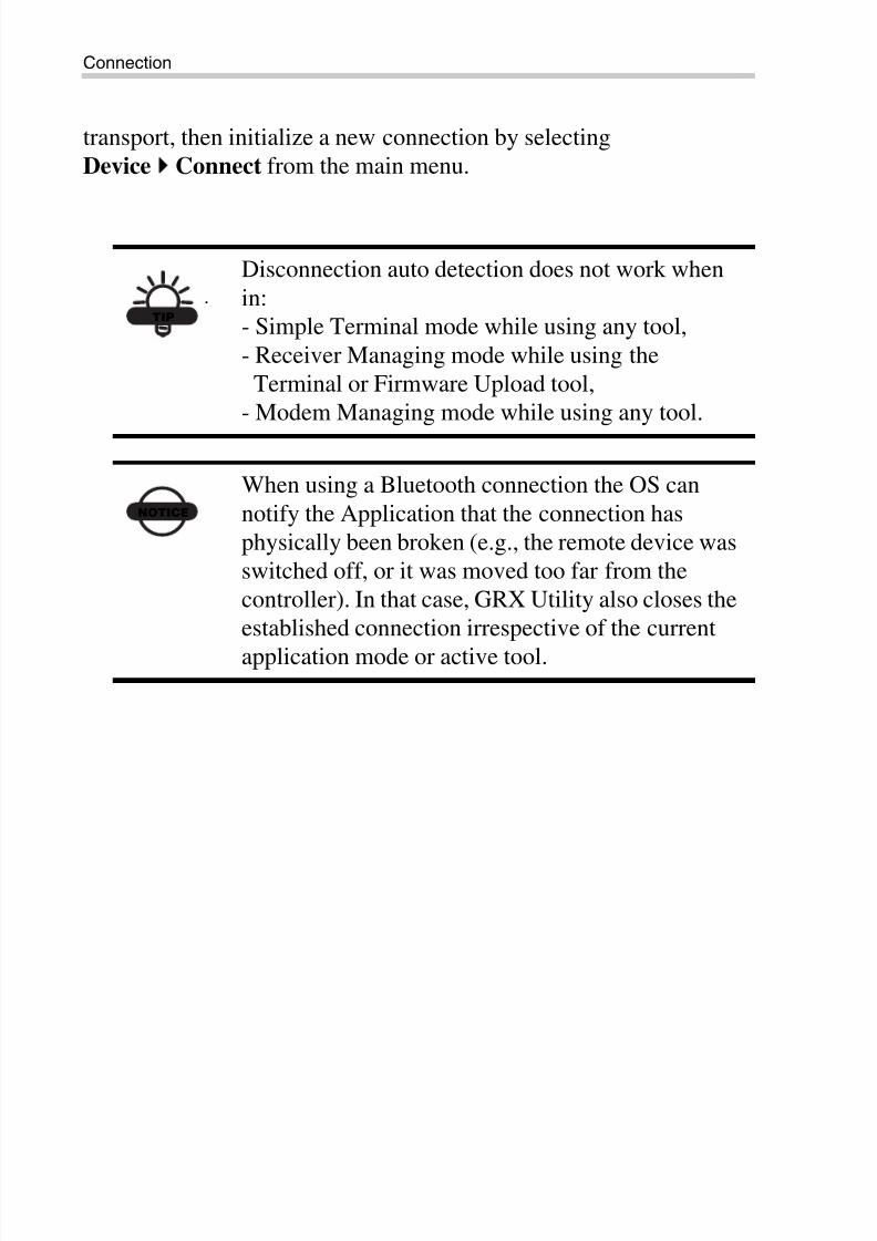
When in Receiver Managing or Modem Managing mode, the
Application periodically checks if the device is still connected byobtaining the receiver ID. If connection to the device is lost, an error
message displays (Figure 2-6).
Figure 2-6. Error Message – Connection to Receiver is Lost
The Application then closes the established connection and makes the
tool area inactive. The Application will not try to reconnect to the
device. You must choose an appropriate application mode and
8/10/2019 7010-0980 - GRX Utility RM.pdf
http://slidepdf.com/reader/full/7010-0980-grx-utility-rmpdf 24/80
Connection
GRX Utility Reference Manual2-6
transport, then initialize a new connection by selecting
Device Connect from the main menu.
TIP
Disconnection auto detection does not work when
in:
- Simple Terminal mode while using any tool,
- Receiver Managing mode while using the
Terminal or Firmware Upload tool,
- Modem Managing mode while using any tool.
NOTICE
When using a Bluetooth connection the OS can
notify the Application that the connection has
physically been broken (e.g., the remote device was
switched off, or it was moved too far from the
controller). In that case, GRX Utility also closes the
established connection irrespective of the current
application mode or active tool.
8/10/2019 7010-0980 - GRX Utility RM.pdf
http://slidepdf.com/reader/full/7010-0980-grx-utility-rmpdf 25/80
P/N 7010-0980
Chapter 3
3-1
Simple TerminalIn Simple Terminal mode, GRX Utility does not:
• detect a device
• adjust port settings
• send any data to the port
This mode is intended for advanced users. Everything is decided by
the user in this pure manual mode.
Simple Manual mode can be used for the following:
• when you want to connect to a device that GRX Utility doesn’t
support.
• when you need to export firmware files to an inoperative receiverthat cannot even be detected (e.g., if the previous firmware
update has not been completed, and the receiver cannot be
detected in Receiver Managing mode).
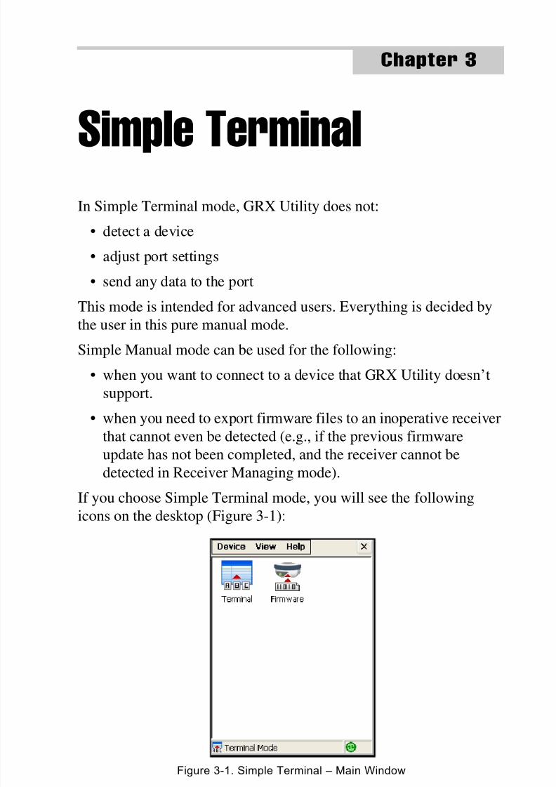
If you choose Simple Terminal mode, you will see the following
icons on the desktop (Figure 3-1):
Figure 3-1. Simple Terminal – Main Window
8/10/2019 7010-0980 - GRX Utility RM.pdf
http://slidepdf.com/reader/full/7010-0980-grx-utility-rmpdf 26/80
Simple Terminal
GRX Utility Reference Manual3-2
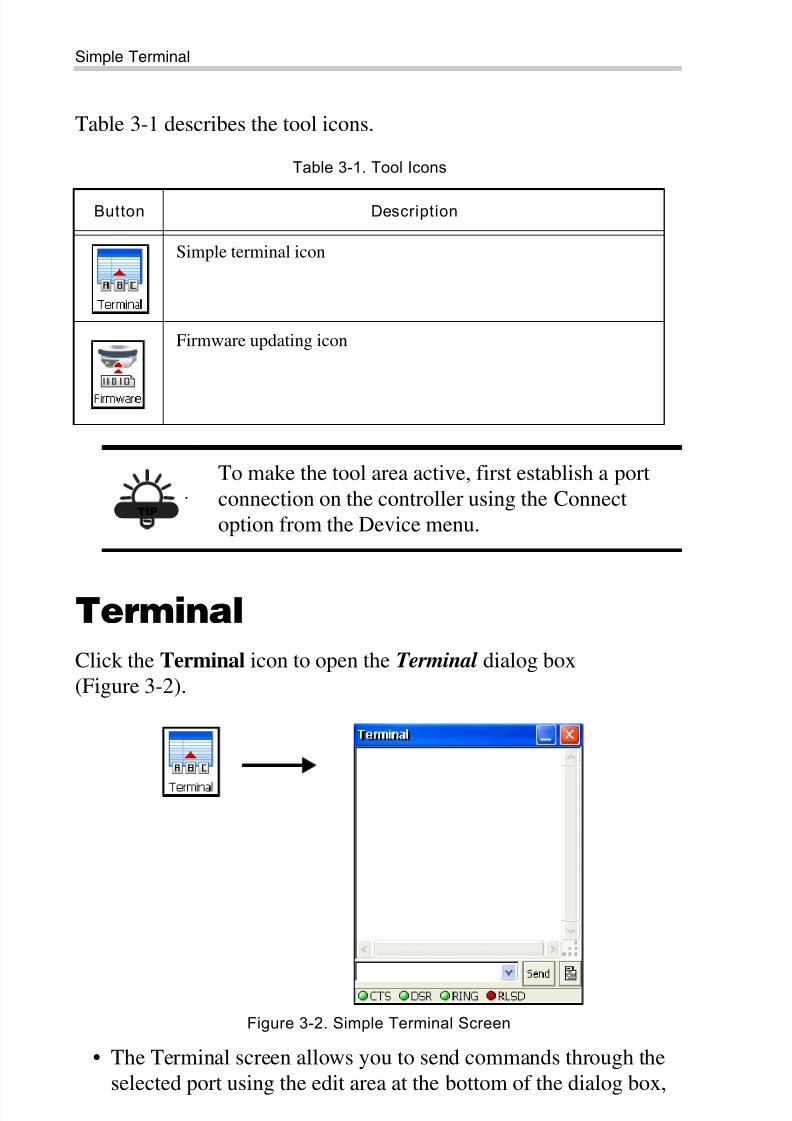
Table 3-1 describes the tool icons.
Terminal
Click the Terminal icon to open the Terminal dialog box
(Figure 3-2).
Figure 3-2. Simple Terminal Screen
• The Terminal screen allows you to send commands through the
selected port using the edit area at the bottom of the dialog box,
Table 3-1. Tool Icons
Button Description
Simple terminal icon
Firmware updating icon
TIP
To make the tool area active, first establish a port
connection on the controller using the Connect
option from the Device menu.
8/10/2019 7010-0980 - GRX Utility RM.pdf
http://slidepdf.com/reader/full/7010-0980-grx-utility-rmpdf 27/80
Terminal
P/N 7010-0980 3-3
and the Send button. The combo box remembers previous
commands, which can be selected from the drop-down list at the
bottom of the dialog.
• The status bar in the lower part of the dialog shows the current
state of transport for specific signals.
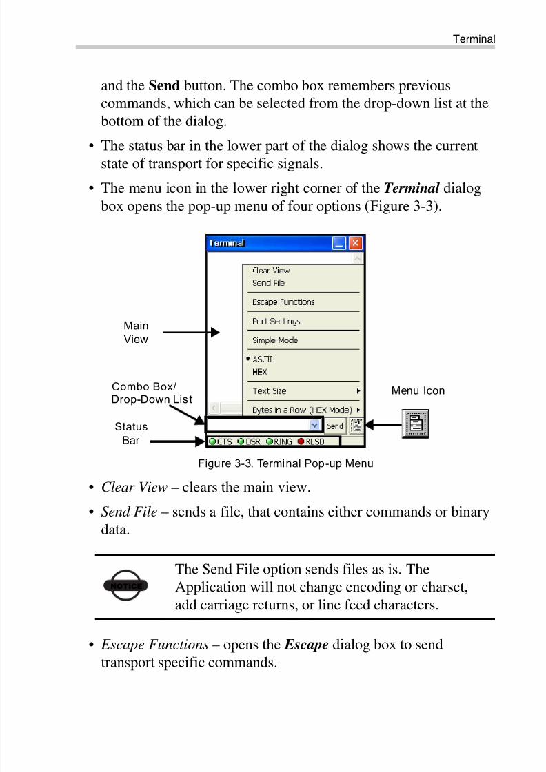
• The menu icon in the lower right corner of the Terminal dialog
box opens the pop-up menu of four options (Figure 3-3).
Figure 3-3. Terminal Pop-up Menu
• Clear View – clears the main view.
• Send File – sends a file, that contains either commands or binary
data.
• Escape Functions – opens the Escape dialog box to send
transport specific commands.
NOTICE
The Send File option sends files as is. The
Application will not change encoding or charset,
add carriage returns, or line feed characters.
Menu Icon
Status
Bar
Main
View
Combo Box/Drop-Down Lis t
8/10/2019 7010-0980 - GRX Utility RM.pdf
http://slidepdf.com/reader/full/7010-0980-grx-utility-rmpdf 28/80
Simple Terminal
GRX Utility Reference Manual3-4
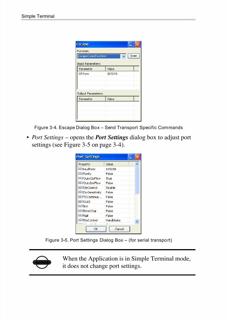
Figure 3-4. Escape Dialog Box – Send Transport Specif ic Commands
• Port Settings – opens the Port Settings dialog box to adjust port
settings (see Figure 3-5 on page 3-4).
Figure 3-5. Port Settings Dialog Box – (for serial transport)
NOTICE
When the Application is in Simple Terminal mode,
it does not change port settings.
8/10/2019 7010-0980 - GRX Utility RM.pdf
http://slidepdf.com/reader/full/7010-0980-grx-utility-rmpdf 29/80
Firmware
P/N 7010-0980 3-5
• Simple Mode – if the Simple Mode item is selected, the terminal
works in a similar way as HyperTerminal. Every time you press a
key the key code is immediately sent to the connected device.If not selecting the Simple Mode, you have to compose a
command in the edit box, then press either the Send button or
Enter, and only after that the entered text (ended with carriage
return and line feed) will be sent to the connected device.
• ASCII/HEX – toggles text/HEX mode.
• Text Size – sets the size of the text (Largest, Larger, Normal,
Smaller, Smallest).
• Bytes in a Row – selects the number of bytes in a row, and
whether you want to display the left hand (data) pane and the
right hand (character) pane. This option applies to HEX mode
only.
FirmwareNormally firmware updating is performed in Receiver Managing
mode. However, if a receiver becomes inoperative, e.g., the previous
receiver firmware updating was not successful; only the Simple
Terminal mode will be available for use.
The firmware updating process in Simple Terminal mode is similar to
that described in Chapter 4, “Receiver Managing” on page 4-1. Thereis only one difference: when in Simple Terminal mode, only the
Power ON capture method is available.
GRX Utility allows uploading firmware files to the GRX receiver
(GMSX board), internal modem and power board.
NOTICE
Port settings depend on the OS. Usually the OS for
the PC remembers the previous port state, so if the
port baud rate was changed, the assigned value willbe kept. CE.NET and Windows Mobile will usually
reset port settings by default. I.e., the next time you
open a serial port, you should adjust port settings
again.
8/10/2019 7010-0980 - GRX Utility RM.pdf
http://slidepdf.com/reader/full/7010-0980-grx-utility-rmpdf 30/80
Simple Terminal
GRX Utility Reference Manual3-6
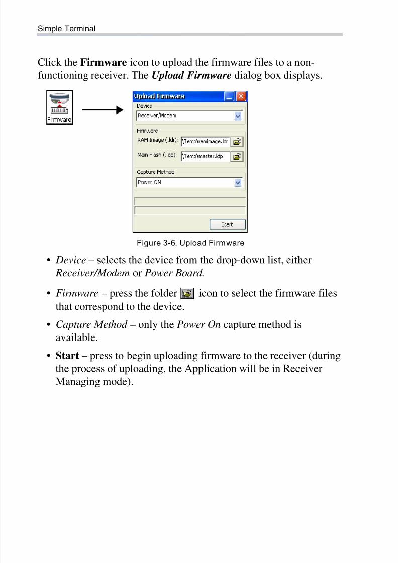
Click the Firmware icon to upload the firmware files to a non-
functioning receiver. The Upload Firmware dialog box displays.
Figure 3-6. Upload Firmware
• Device – selects the device from the drop-down list, either
Receiver/Modem or Power Board.
• Firmware – press the folder icon to select the firmware filesthat correspond to the device.
• Capture Method – only the Power On capture method is
available.
• Start – press to begin uploading firmware to the receiver (during
the process of uploading, the Application will be in Receiver
Managing mode).
8/10/2019 7010-0980 - GRX Utility RM.pdf
http://slidepdf.com/reader/full/7010-0980-grx-utility-rmpdf 31/80
P/N 7010-0980
Chapter 4
4-1
Receiver ManagingReceiver Managing mode is intended for configuring GRX receivers
and updating firmware of GRX1 receiver boards, internal modems,
power, and Bluetooth modules.
When in Receiver Managing mode, the Application tries to detect a
receiver at the time of connection. If there is no receiver, or if it
doesn’t respond, a connection cannot be established.
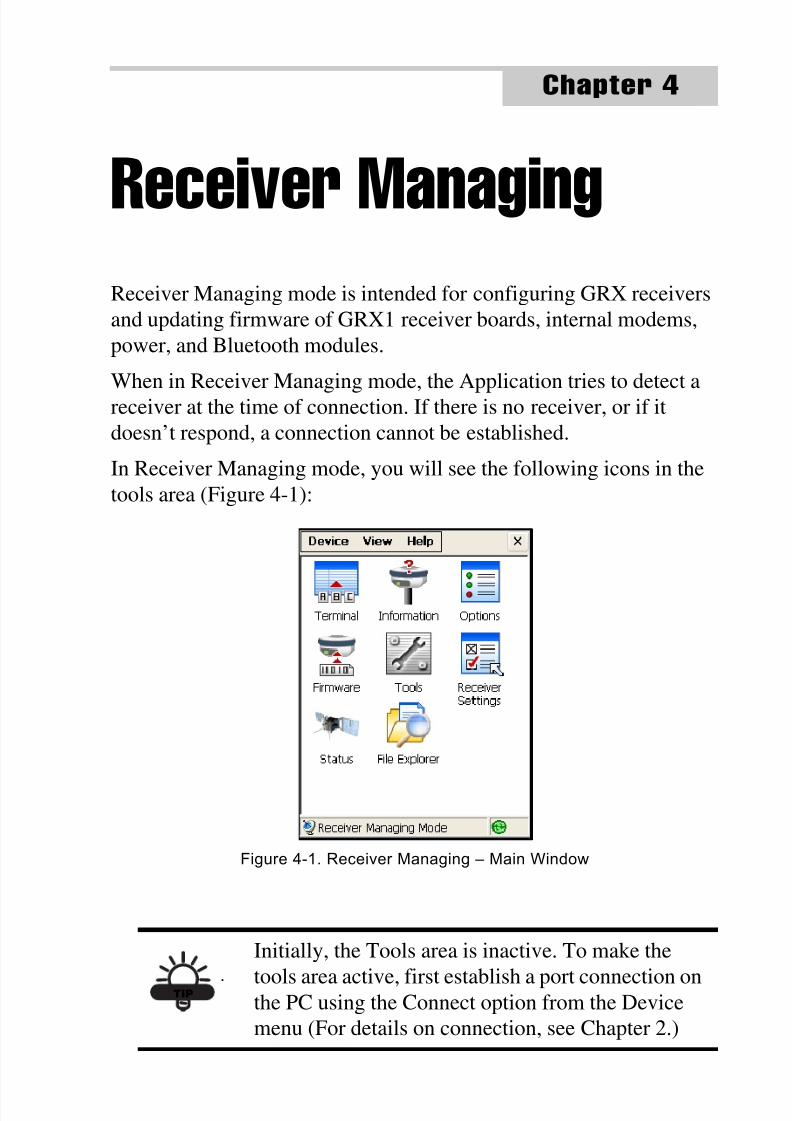
In Receiver Managing mode, you will see the following icons in the
tools area (Figure 4-1):
Figure 4-1. Receiver Managing – Main Window
TIP
Initially, the Tools area is inactive. To make the
tools area active, first establish a port connection onthe PC using the Connect option from the Device
menu (For details on connection, see Chapter 2.)
8/10/2019 7010-0980 - GRX Utility RM.pdf
http://slidepdf.com/reader/full/7010-0980-grx-utility-rmpdf 32/80
Receiver Managing
GRX Utility Reference Manual4-2
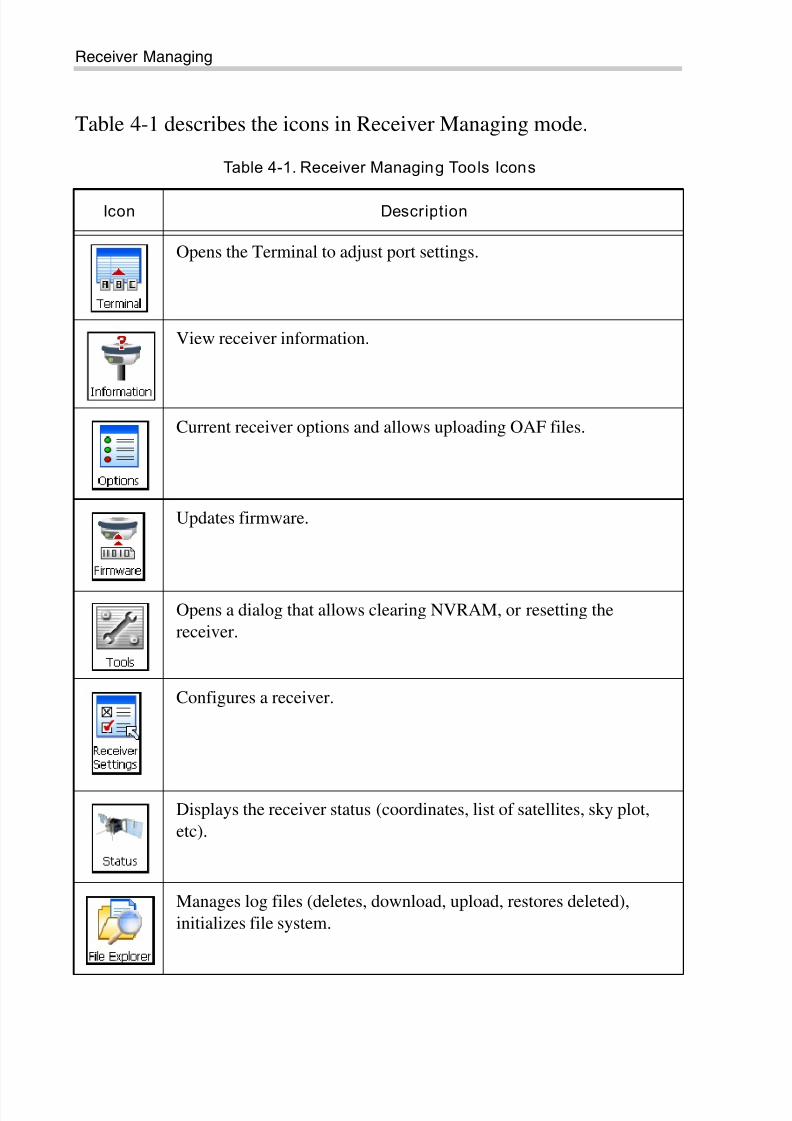
Table 4-1 describes the icons in Receiver Managing mode.
Table 4-1. Receiver Managing Tools Icons
Icon Description
Opens the Terminal to adjust port settings.
View receiver information.
Current receiver options and allows uploading OAF files.
Updates firmware.
Opens a dialog that allows clearing NVRAM, or resetting the
receiver.
Configures a receiver.
Displays the receiver status (coordinates, list of satellites, sky plot,
etc).
Manages log files (deletes, download, upload, restores deleted),
initializes file system.
8/10/2019 7010-0980 - GRX Utility RM.pdf
http://slidepdf.com/reader/full/7010-0980-grx-utility-rmpdf 33/80
Terminal
P/N 7010-0980 4-3
Terminal
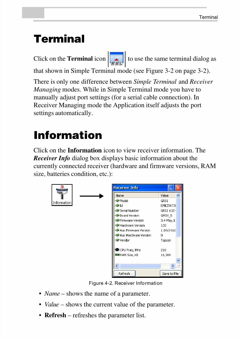
Click on the Terminal icon to use the same terminal dialog as
that shown in Simple Terminal mode (see Figure 3-2 on page 3-2).
There is only one difference between Simple Terminal and Receiver
Managing modes. While in Simple Terminal mode you have to
manually adjust port settings (for a serial cable connection). In
Receiver Managing mode the Application itself adjusts the port
settings automatically.
Information
Click on the Information icon to view receiver information. The
Receiver Info dialog box displays basic information about the
currently connected receiver (hardware and firmware versions, RAM
size, batteries condition, etc.):
Figure 4-2. Receiver Information
• Name – shows the name of a parameter.
• Value – shows the current value of the parameter.
• Refresh – refreshes the parameter list.
8/10/2019 7010-0980 - GRX Utility RM.pdf
http://slidepdf.com/reader/full/7010-0980-grx-utility-rmpdf 34/80
Receiver Managing
GRX Utility Reference Manual4-4
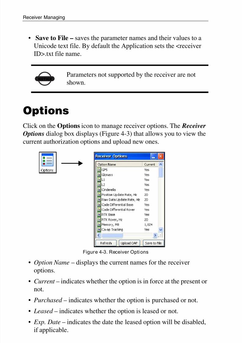
• Save to File – saves the parameter names and their values to a
Unicode text file. By default the Application sets the <receiver
ID>.txt file name.
Options
Click on the Options icon to manage receiver options. The Receiver
Options dialog box displays (Figure 4-3) that allows you to view the
current authorization options and upload new ones.
Figure 4-3. Receiver Options
• Option Name – displays the current names for the receiver
options.
• Current – indicates whether the option is in force at the present or
not.
• Purchased – indicates whether the option is purchased or not.
• Leased – indicates whether the option is leased or not.
• Exp. Date – indicates the date the leased option will be disabled,
if applicable.
NOTICE
Parameters not supported by the receiver are not
shown.
8/10/2019 7010-0980 - GRX Utility RM.pdf
http://slidepdf.com/reader/full/7010-0980-grx-utility-rmpdf 35/80
Options
P/N 7010-0980 4-5
• Refresh – refreshes contents of the options.
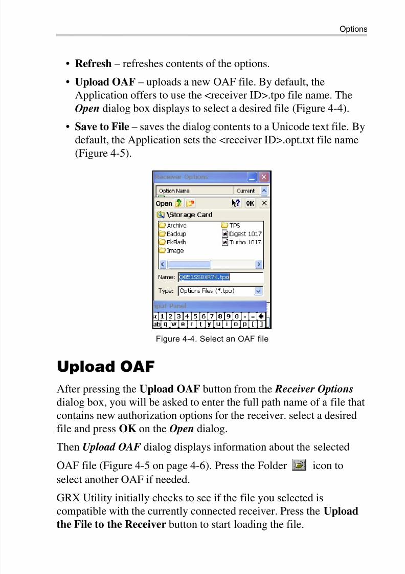
• Upload OAF – uploads a new OAF file. By default, the
Application offers to use the <receiver ID>.tpo file name. TheOpen dialog box displays to select a desired file (Figure 4-4).
• Save to File – saves the dialog contents to a Unicode text file. By
default, the Application sets the <receiver ID>.opt.txt file name
(Figure 4-5).
Figure 4-4. Select an OAF file
Upload OAF
After pressing the Upload OAF button from the Receiver Options
dialog box, you will be asked to enter the full path name of a file thatcontains new authorization options for the receiver. select a desired
file and press OK on the Open dialog.
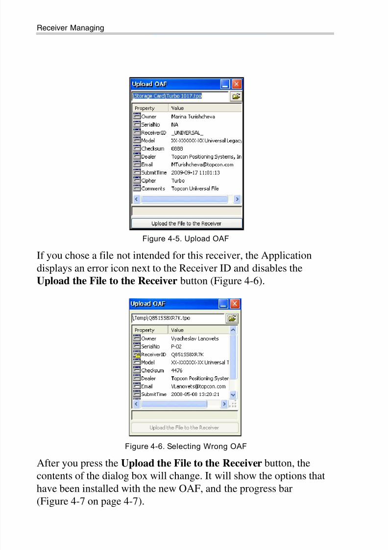
Then Upload OAF dialog displays information about the selected
OAF file (Figure 4-5 on page 4-6). Press the Folder icon to
select another OAF if needed.
GRX Utility initially checks to see if the file you selected iscompatible with the currently connected receiver. Press the Upload
the File to the Receiver button to start loading the file.
8/10/2019 7010-0980 - GRX Utility RM.pdf
http://slidepdf.com/reader/full/7010-0980-grx-utility-rmpdf 36/80
Receiver Managing
GRX Utility Reference Manual4-6
Figure 4-5. Upload OAF
If you chose a file not intended for this receiver, the Application
displays an error icon next to the Receiver ID and disables the
Upload the File to the Receiver button (Figure 4-6).
Figure 4-6. Selecting Wrong OAF
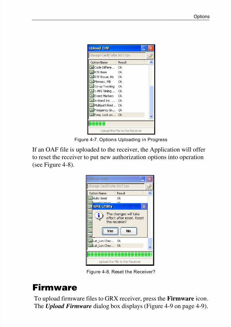
After you press the Upload the File to the Receiver button, the
contents of the dialog box will change. It will show the options that
have been installed with the new OAF, and the progress bar
(Figure 4-7 on page 4-7).
8/10/2019 7010-0980 - GRX Utility RM.pdf
http://slidepdf.com/reader/full/7010-0980-grx-utility-rmpdf 37/80
Options
P/N 7010-0980 4-7
Figure 4-7. Options Uploading in Progress
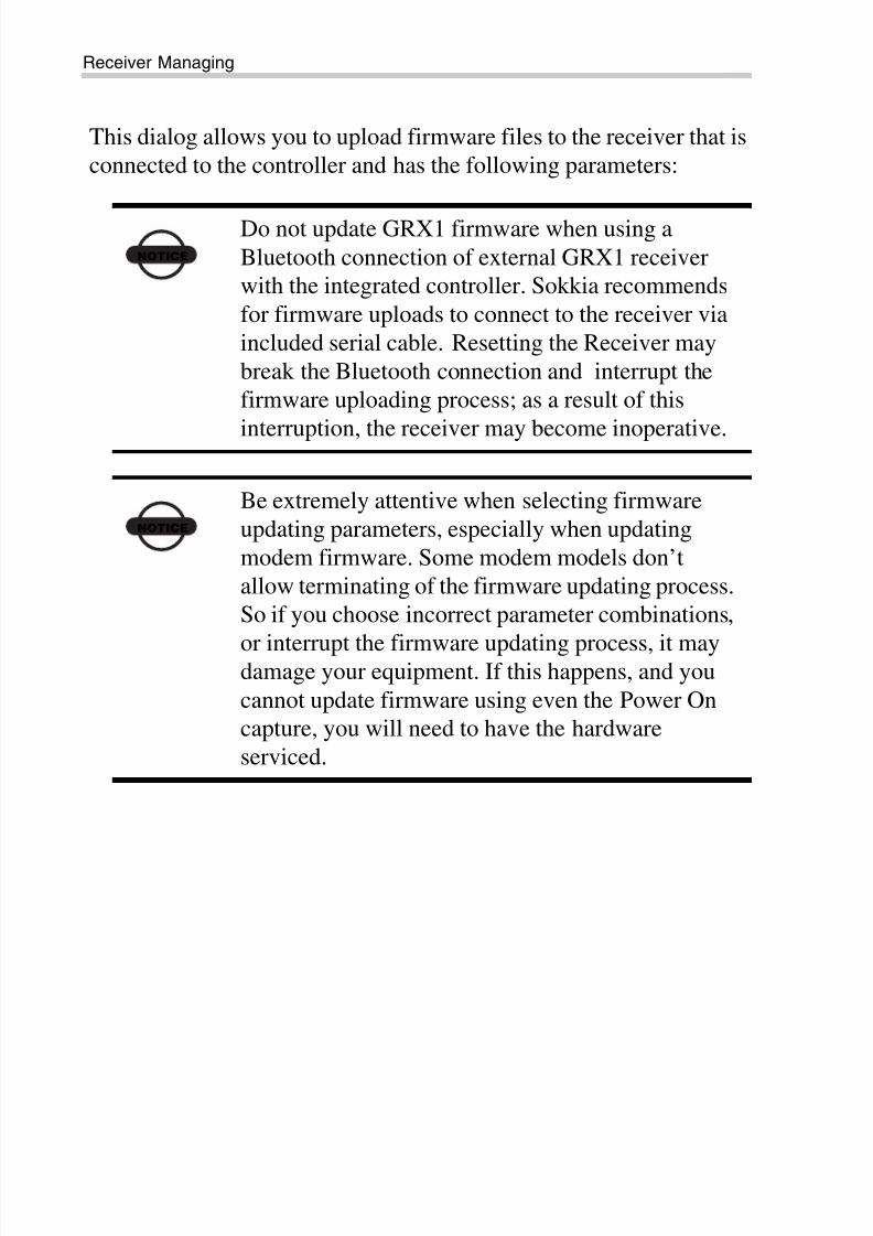
If an OAF file is uploaded to the receiver, the Application will offer
to reset the receiver to put new authorization options into operation
(see Figure 4-8).
Figure 4-8. Reset the Receiver?
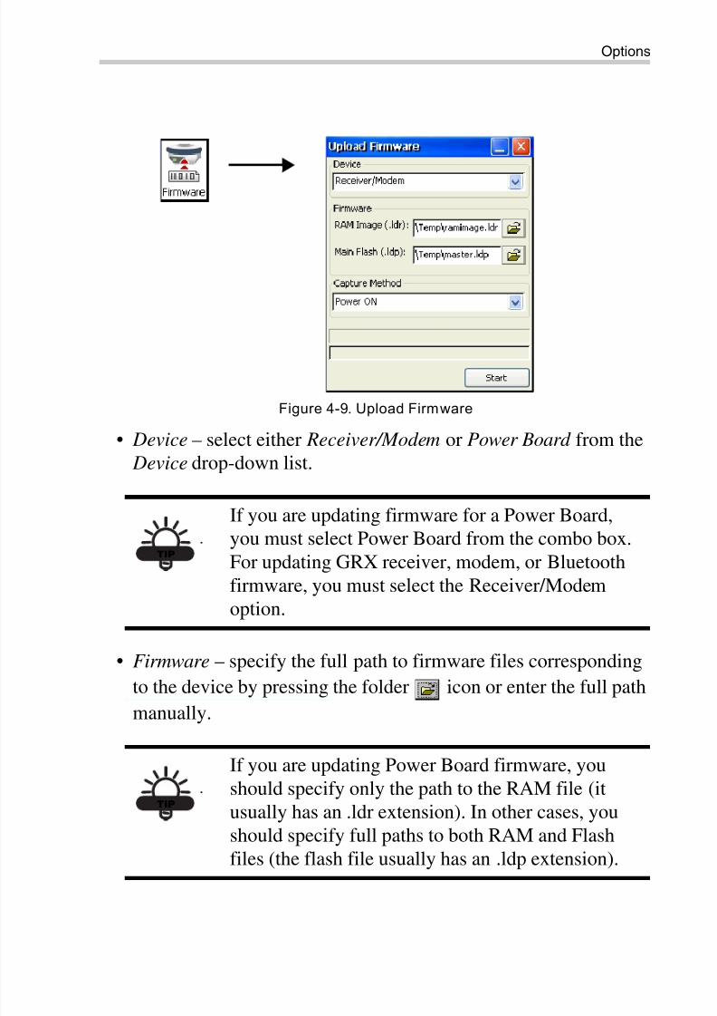
FirmwareTo upload firmware files to GRX receiver, press the Firmware icon.
The Upload Firmware dialog box displays (Figure 4-9 on page 4-9).
8/10/2019 7010-0980 - GRX Utility RM.pdf
http://slidepdf.com/reader/full/7010-0980-grx-utility-rmpdf 38/80
Receiver Managing
GRX Utility Reference Manual4-8
This dialog allows you to upload firmware files to the receiver that is
connected to the controller and has the following parameters:
NOTICE
Do not update GRX1 firmware when using a
Bluetooth connection of external GRX1 receiver
with the integrated controller. Sokkia recommends
for firmware uploads to connect to the receiver via
included serial cable. Resetting the Receiver may
break the Bluetooth connection and interrupt the
firmware uploading process; as a result of this
interruption, the receiver may become inoperative.
NOTICE
Be extremely attentive when selecting firmware
updating parameters, especially when updating
modem firmware. Some modem models don’t
allow terminating of the firmware updating process.
So if you choose incorrect parameter combinations,
or interrupt the firmware updating process, it maydamage your equipment. If this happens, and you
cannot update firmware using even the Power On
capture, you will need to have the hardware
serviced.
8/10/2019 7010-0980 - GRX Utility RM.pdf
http://slidepdf.com/reader/full/7010-0980-grx-utility-rmpdf 39/80
Options
P/N 7010-0980 4-9
Figure 4-9. Upload Firmware
• Device – select either Receiver/Modem or Power Board from the
Device drop-down list.
• Firmware – specify the full path to firmware files corresponding
to the device by pressing the folder icon or enter the full path
manually.
TIP
If you are updating firmware for a Power Board,
you must select Power Board from the combo box.For updating GRX receiver, modem, or Bluetooth
firmware, you must select the Receiver/Modem
option.
TIP
If you are updating Power Board firmware, you
should specify only the path to the RAM file (it
usually has an .ldr extension). In other cases, you
should specify full paths to both RAM and Flash
files (the flash file usually has an .ldp extension).
8/10/2019 7010-0980 - GRX Utility RM.pdf
http://slidepdf.com/reader/full/7010-0980-grx-utility-rmpdf 40/80
Receiver Managing
GRX Utility Reference Manual4-10
• Capture Method – select either the Soft Break , or the Power ON
capture method. If you select the Soft Break method, the receiver
will be switched into firmware updating mode through the
software. If you select the Power ON capture method, after youpress the Start button, you will need to press the reset button on
the receiver, or turn it off, then on again.
• Start – press to begin uploading firmware to the receiver in
Receiver Managing mode. After you press the button, it toggles
to Cancel. Pressing this button terminates the firmware updating
process.
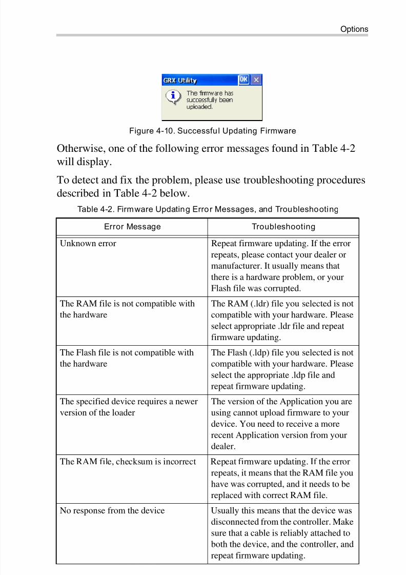
After the firmware updating process has been successful (uploaded),
the following message displays (see Figure 4-10 on page 4-11):
NOTICE
Firmware for the GRX1 receiver consists of one
RAM file and two Flash files (usually Master.ldp,
and Slave.ldp).
You have to update receiver firmware in two
iterations:
1) Select the RAM file and the first Flash file, then
perform firmware updating.
2) Once this firmware is successfully uploaded, you
select the same RAM file and the other Flash file,then repeat firmware upgrading.
NOTICE
If the firmware updating process for a device has
not been completed, the device may become
inoperative.
8/10/2019 7010-0980 - GRX Utility RM.pdf
http://slidepdf.com/reader/full/7010-0980-grx-utility-rmpdf 41/80
Options
P/N 7010-0980 4-11
Figure 4-10. Successful Updating Firmware
Otherwise, one of the following error messages found in Table 4-2
will display.
To detect and fix the problem, please use troubleshooting procedures
described in Table 4-2 below.
Table 4-2. Firmware Updating Error Messages, and Troubleshooting
Error Message Troubleshooting
Unknown error Repeat firmware updating. If the error
repeats, please contact your dealer or
manufacturer. It usually means that
there is a hardware problem, or your
Flash file was corrupted.
The RAM file is not compatible withthe hardware
The RAM (.ldr) file you selected is notcompatible with your hardware. Please
select appropriate .ldr file and repeat
firmware updating.
The Flash file is not compatible with
the hardware
The Flash (.ldp) file you selected is not
compatible with your hardware. Please
select the appropriate .ldp file and
repeat firmware updating.
The specified device requires a newerversion of the loader
The version of the Application you areusing cannot upload firmware to your
device. You need to receive a more
recent Application version from your
dealer.
The RAM file, checksum is incorrect Repeat firmware updating. If the error
repeats, it means that the RAM file you
have was corrupted, and it needs to be
replaced with correct RAM file.
No response from the device Usually this means that the device was
disconnected from the controller. Make
sure that a cable is reliably attached to
both the device, and the controller, and
repeat firmware updating.
8/10/2019 7010-0980 - GRX Utility RM.pdf
http://slidepdf.com/reader/full/7010-0980-grx-utility-rmpdf 42/80
Receiver Managing
GRX Utility Reference Manual4-12
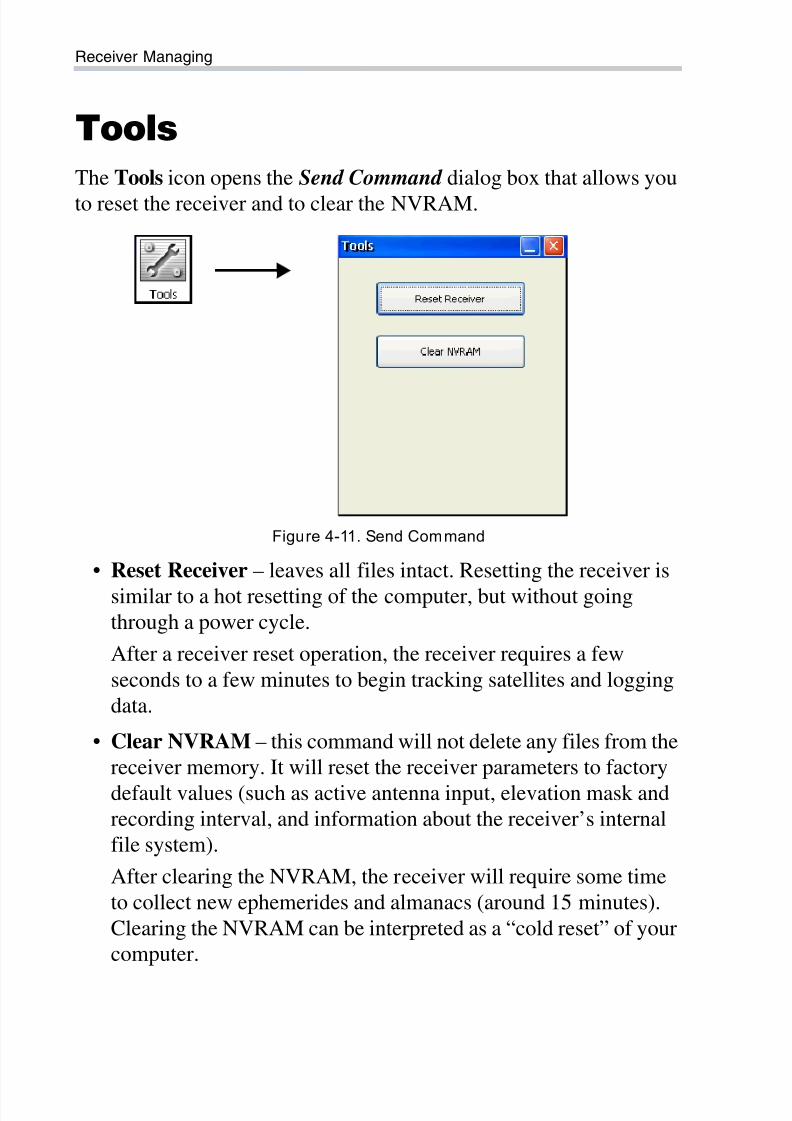
Tools
The Tools icon opens the Send Command dialog box that allows you
to reset the receiver and to clear the NVRAM.
Figure 4-11. Send Command
• Reset Receiver – leaves all files intact. Resetting the receiver is
similar to a hot resetting of the computer, but without goingthrough a power cycle.
After a receiver reset operation, the receiver requires a few
seconds to a few minutes to begin tracking satellites and logging
data.
• Clear NVRAM – this command will not delete any files from the
receiver memory. It will reset the receiver parameters to factory
default values (such as active antenna input, elevation mask and
recording interval, and information about the receiver’s internal
file system).
After clearing the NVRAM, the receiver will require some time
to collect new ephemerides and almanacs (around 15 minutes).
Clearing the NVRAM can be interpreted as a “cold reset” of your
computer.
8/10/2019 7010-0980 - GRX Utility RM.pdf
http://slidepdf.com/reader/full/7010-0980-grx-utility-rmpdf 43/80
Receiver Settings
P/N 7010-0980 4-13
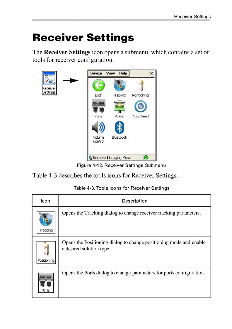
Receiver Settings
The Receiver Settings icon opens a submenu, which contains a set of
tools for receiver configuration.
Figure 4-12. Receiver Settings Submenu
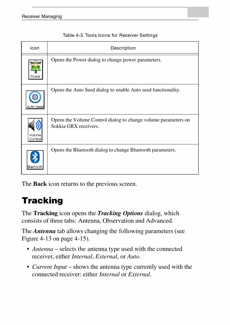
Table 4-3 describes the tools icons for Receiver Settings.
Table 4-3. Tools Icons for Receiver Settings
Icon Description
Opens the Tracking dialog to change receiver tracking parameters.
Opens the Positioning dialog to change positioning mode and enable
a desired solution type.
Opens the Ports dialog to change parameters for ports configuration.
8/10/2019 7010-0980 - GRX Utility RM.pdf
http://slidepdf.com/reader/full/7010-0980-grx-utility-rmpdf 44/80
Receiver Managing
GRX Utility Reference Manual4-14
The Back icon returns to the previous screen.
Tracking
The Tracking icon opens the Tracking Options dialog, which
consists of three tabs: Antenna, Observation and Advanced.
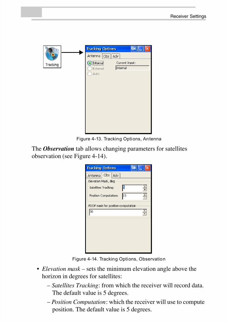
The Antenna tab allows changing the following parameters (see
Figure 4-13 on page 4-15).
• Antenna – selects the antenna type used with the connected
receiver, either Internal, External, or Auto.
• Current Input – shows the antenna type currently used with the
connected receiver: either Internal or External.
Opens the Power dialog to change power parameters.
Opens the Auto Seed dialog to enable Auto seed functionality.
Opens the Volume Control dialog to change volume parameters on
Sokkia GRX receivers.
Opens the Bluetooth dialog to change Bluetooth parameters.
Table 4-3. Tools Icons for Receiver Settings
Icon Description
8/10/2019 7010-0980 - GRX Utility RM.pdf
http://slidepdf.com/reader/full/7010-0980-grx-utility-rmpdf 45/80
Receiver Settings
P/N 7010-0980 4-15
Figure 4-13. Tracking Options, Antenna
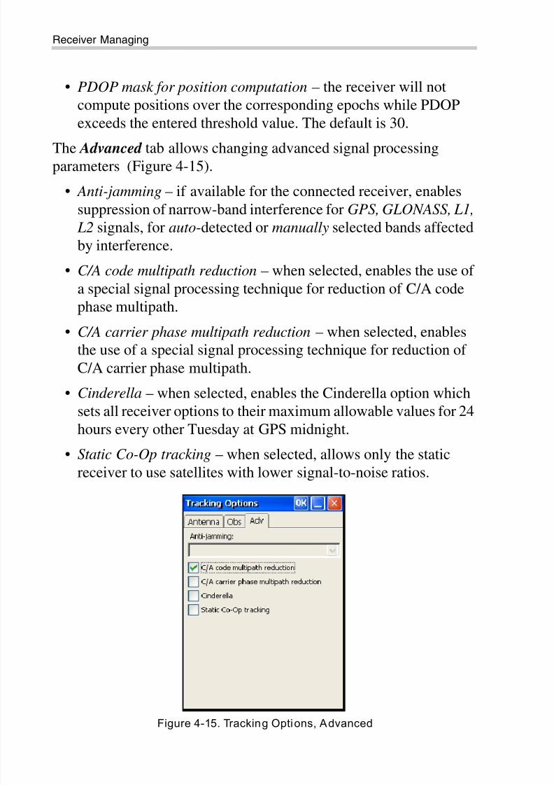
The Observation tab allows changing parameters for satellites
observation (see Figure 4-14).
Figure 4-14. Tracking Options, Observation
• Elevation mask – sets the minimum elevation angle above the
horizon in degrees for satellites:
– Satellites Tracking: from which the receiver will record data.
The default value is 5 degrees.
– Position Computation: which the receiver will use to compute
position. The default value is 5 degrees.
8/10/2019 7010-0980 - GRX Utility RM.pdf
http://slidepdf.com/reader/full/7010-0980-grx-utility-rmpdf 46/80
Receiver Managing
GRX Utility Reference Manual4-16
• PDOP mask for position computation – the receiver will not
compute positions over the corresponding epochs while PDOP
exceeds the entered threshold value. The default is 30.
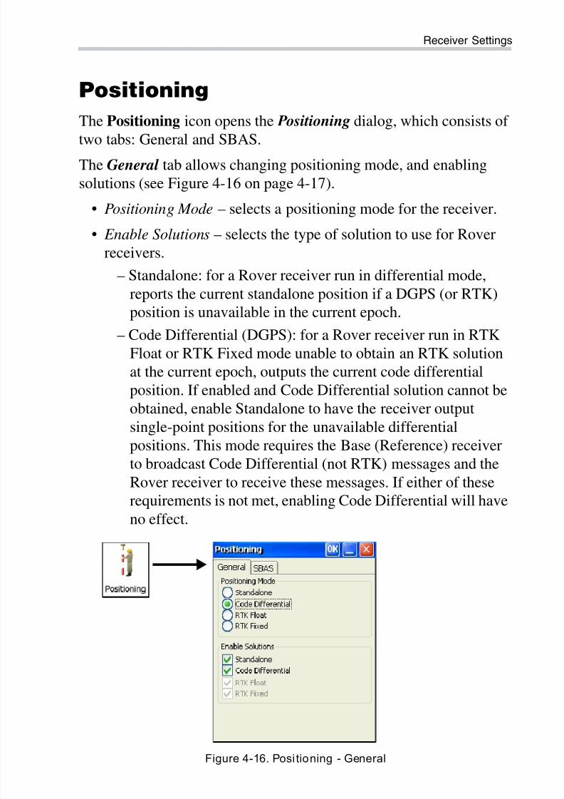
The Advanced tab allows changing advanced signal processing
parameters (Figure 4-15).
• Anti-jamming – if available for the connected receiver, enables
suppression of narrow-band interference for GPS, GLONASS, L1,
L2 signals, for auto-detected or manually selected bands affected
by interference.
• C/A code multipath reduction – when selected, enables the use ofa special signal processing technique for reduction of C/A code
phase multipath.
• C/A carrier phase multipath reduction – when selected, enables
the use of a special signal processing technique for reduction of
C/A carrier phase multipath.
• Cinderella – when selected, enables the Cinderella option which
sets all receiver options to their maximum allowable values for 24hours every other Tuesday at GPS midnight.
• Static Co-Op tracking – when selected, allows only the static
receiver to use satellites with lower signal-to-noise ratios.
Figure 4-15. Tracking Options, Advanced
8/10/2019 7010-0980 - GRX Utility RM.pdf
http://slidepdf.com/reader/full/7010-0980-grx-utility-rmpdf 47/80
Receiver Settings
P/N 7010-0980 4-17
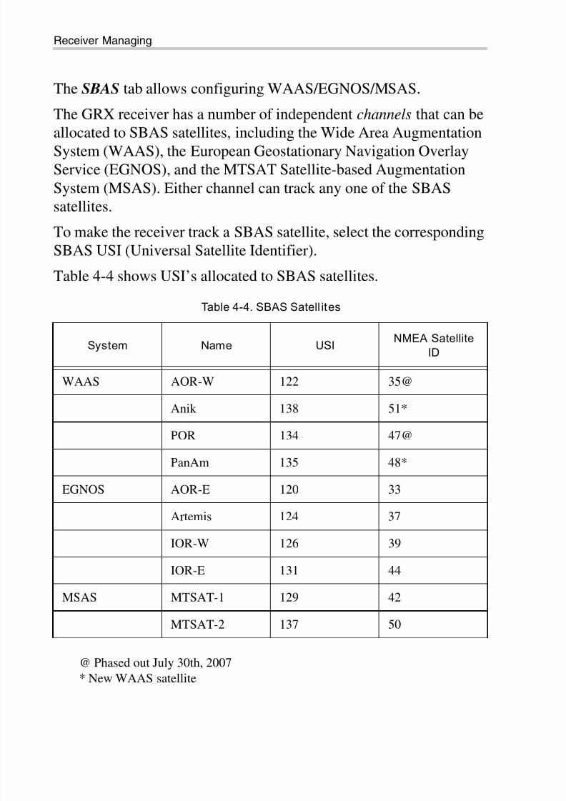
Positioning
The Positioning icon opens the Positioning dialog, which consists of
two tabs: General and SBAS.
The General tab allows changing positioning mode, and enabling
solutions (see Figure 4-16 on page 4-17).
• Positioning Mode – selects a positioning mode for the receiver.
• Enable Solutions – selects the type of solution to use for Rover
receivers.
– Standalone: for a Rover receiver run in differential mode,reports the current standalone position if a DGPS (or RTK)
position is unavailable in the current epoch.
– Code Differential (DGPS): for a Rover receiver run in RTK
Float or RTK Fixed mode unable to obtain an RTK solution
at the current epoch, outputs the current code differential
position. If enabled and Code Differential solution cannot be
obtained, enable Standalone to have the receiver output
single-point positions for the unavailable differential
positions. This mode requires the Base (Reference) receiver
to broadcast Code Differential (not RTK) messages and the
Rover receiver to receive these messages. If either of these
requirements is not met, enabling Code Differential will have
no effect.
Figure 4-16. Positioning - General
8/10/2019 7010-0980 - GRX Utility RM.pdf
http://slidepdf.com/reader/full/7010-0980-grx-utility-rmpdf 48/80
Receiver Managing
GRX Utility Reference Manual4-18
The SBAS tab allows configuring WAAS/EGNOS/MSAS.
The GRX receiver has a number of independent channels that can be
allocated to SBAS satellites, including the Wide Area AugmentationSystem (WAAS), the European Geostationary Navigation Overlay
Service (EGNOS), and the MTSAT Satellite-based Augmentation
System (MSAS). Either channel can track any one of the SBAS
satellites.
To make the receiver track a SBAS satellite, select the corresponding
SBAS USI (Universal Satellite Identifier).
Table 4-4 shows USI’s allocated to SBAS satellites.
@ Phased out July 30th, 2007
* New WAAS satellite
Table 4-4. SBAS Satell ites
System Name USINMEA Satellite
ID
WAAS AOR-W 122 35@
Anik 138 51*
POR 134 47@
PanAm 135 48*
EGNOS AOR-E 120 33
Artemis 124 37
IOR-W 126 39
IOR-E 131 44
MSAS MTSAT-1 129 42
MTSAT-2 137 50
8/10/2019 7010-0980 - GRX Utility RM.pdf
http://slidepdf.com/reader/full/7010-0980-grx-utility-rmpdf 49/80
Receiver Settings
P/N 7010-0980 4-19
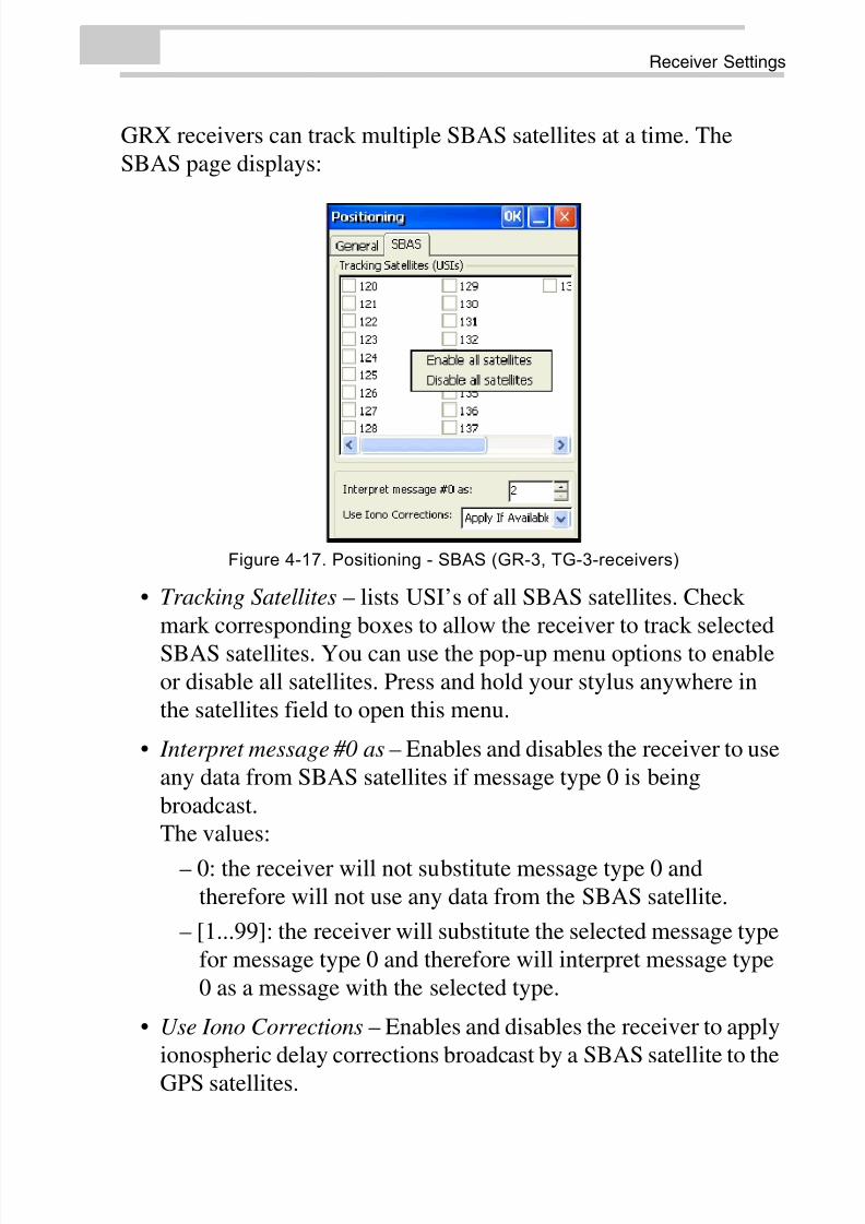
GRX receivers can track multiple SBAS satellites at a time. The
SBAS page displays:
Figure 4-17. Positioning - SBAS (GR-3, TG-3-receivers)
• Tracking Satellites – lists USI’s of all SBAS satellites. Check
mark corresponding boxes to allow the receiver to track selected
SBAS satellites. You can use the pop-up menu options to enable
or disable all satellites. Press and hold your stylus anywhere in
the satellites field to open this menu.
• Interpret message #0 as – Enables and disables the receiver to use
any data from SBAS satellites if message type 0 is being
broadcast.
The values:
– 0: the receiver will not substitute message type 0 and
therefore will not use any data from the SBAS satellite.
– [1...99]: the receiver will substitute the selected message type
for message type 0 and therefore will interpret message type
0 as a message with the selected type.
• Use Iono Corrections – Enables and disables the receiver to apply
ionospheric delay corrections broadcast by a SBAS satellite to the
GPS satellites.
8/10/2019 7010-0980 - GRX Utility RM.pdf
http://slidepdf.com/reader/full/7010-0980-grx-utility-rmpdf 50/80
Receiver Managing
GRX Utility Reference Manual4-20
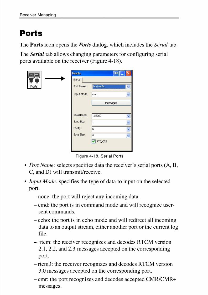
Ports
The Ports icon opens the Ports dialog, which includes the Serial tab.
The Serial tab allows changing parameters for configuring serial
ports available on the receiver (Figure 4-18).
Figure 4-18. Serial Ports
• Port Name: selects specifies data the receiver’s serial ports (A, B,
C, and D) will transmit/receive.
• Input Mode: specifies the type of data to input on the selected
port.
– none: the port will reject any incoming data.
– cmd: the port is in command mode and will recognize user-sent commands.
– echo: the port is in echo mode and will redirect all incoming
data to an output stream, either another port or the current log
file.
– rtcm: the receiver recognizes and decodes RTCM version
2.1, 2.2, and 2.3 messages accepted on the corresponding
port.– rtcm3: the receiver recognizes and decodes RTCM version
3.0 messages accepted on the corresponding port.
– cmr: the port recognizes and decodes accepted CMR/CMR+
messages.
8/10/2019 7010-0980 - GRX Utility RM.pdf
http://slidepdf.com/reader/full/7010-0980-grx-utility-rmpdf 51/80
Receiver Settings
P/N 7010-0980 4-21
– jps: the port recognizes and decodes accepted TPS messages.
– omni: the port recognizes and decodes OmniSTAR VBS
corrections.
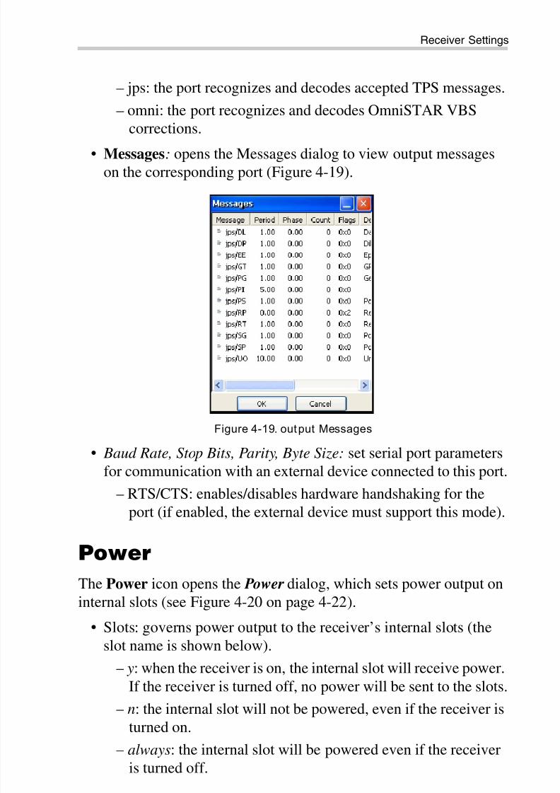
• Messages: opens the Messages dialog to view output messages
on the corresponding port (Figure 4-19).
Figure 4-19. output Messages
• Baud Rate, Stop Bits, Parity, Byte Size: set serial port parameters
for communication with an external device connected to this port.
– RTS/CTS: enables/disables hardware handshaking for the
port (if enabled, the external device must support this mode).
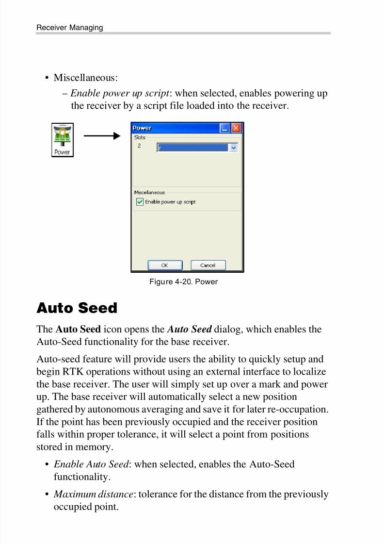
PowerThe Power icon opens the Power dialog, which sets power output on
internal slots (see Figure 4-20 on page 4-22).
• Slots: governs power output to the receiver’s internal slots (the
slot name is shown below).
– y: when the receiver is on, the internal slot will receive power.
If the receiver is turned off, no power will be sent to the slots.
– n: the internal slot will not be powered, even if the receiver is
turned on.
– always: the internal slot will be powered even if the receiver
is turned off.
8/10/2019 7010-0980 - GRX Utility RM.pdf
http://slidepdf.com/reader/full/7010-0980-grx-utility-rmpdf 52/80
Receiver Managing
GRX Utility Reference Manual4-22
• Miscellaneous:
– Enable power up script : when selected, enables powering upthe receiver by a script file loaded into the receiver.
Figure 4-20. Power
Auto Seed
The Auto Seed icon opens the Auto Seed dialog, which enables the
Auto-Seed functionality for the base receiver.
Auto-seed feature will provide users the ability to quickly setup and
begin RTK operations without using an external interface to localize
the base receiver. The user will simply set up over a mark and powerup. The base receiver will automatically select a new position
gathered by autonomous averaging and save it for later re-occupation.
If the point has been previously occupied and the receiver position
falls within proper tolerance, it will select a point from positions
stored in memory.
• Enable Auto Seed : when selected, enables the Auto-Seed
functionality.
• Maximum distance: tolerance for the distance from the previously
occupied point.
8/10/2019 7010-0980 - GRX Utility RM.pdf
http://slidepdf.com/reader/full/7010-0980-grx-utility-rmpdf 53/80
Receiver Settings
P/N 7010-0980 4-23
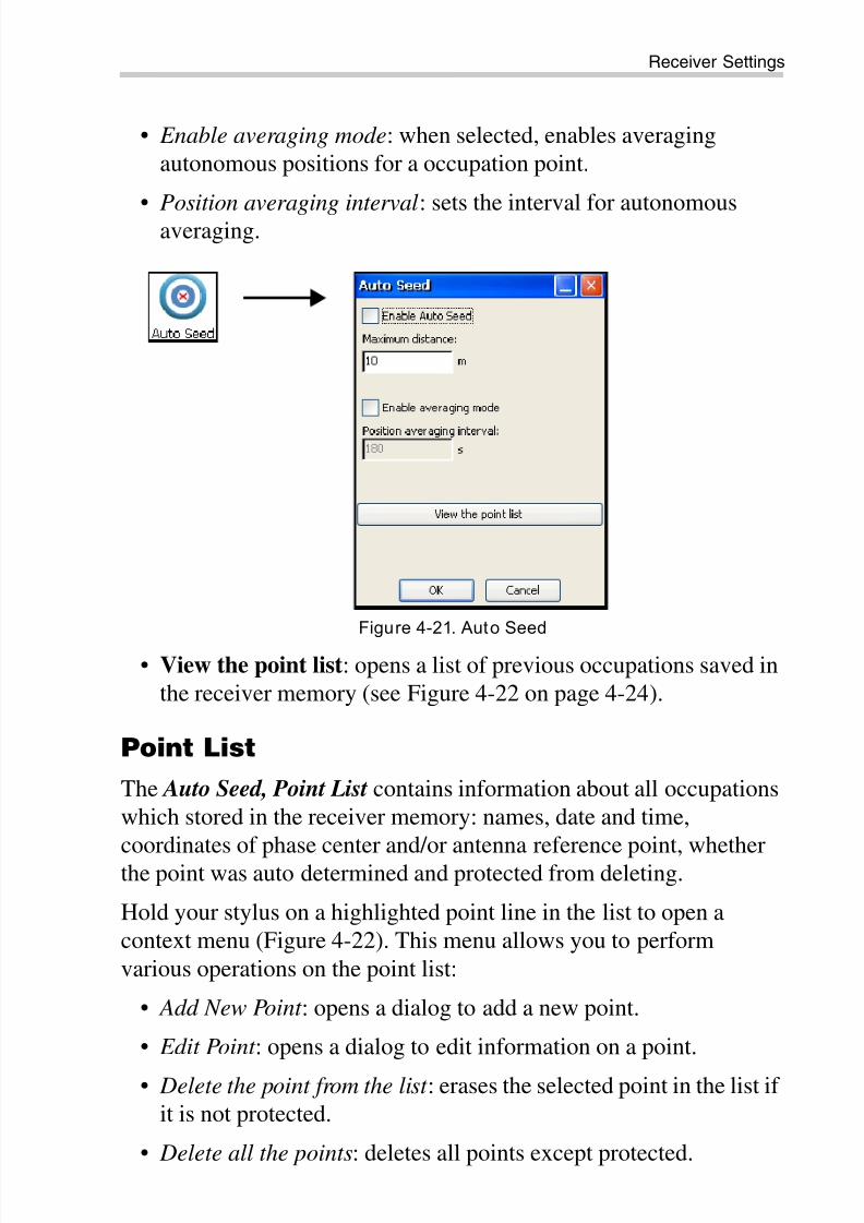
• Enable averaging mode: when selected, enables averaging
autonomous positions for a occupation point.
• Position averaging interval: sets the interval for autonomousaveraging.
Figure 4-21. Auto Seed
• View the point list: opens a list of previous occupations saved in
the receiver memory (see Figure 4-22 on page 4-24).
Point List
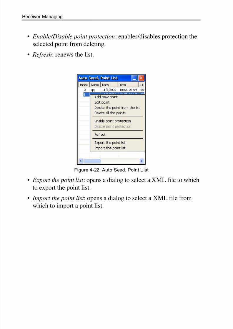
The Auto Seed, Point List contains information about all occupations
which stored in the receiver memory: names, date and time,
coordinates of phase center and/or antenna reference point, whetherthe point was auto determined and protected from deleting.
Hold your stylus on a highlighted point line in the list to open a
context menu (Figure 4-22). This menu allows you to perform
various operations on the point list:
• Add New Point : opens a dialog to add a new point.
• Edit Point : opens a dialog to edit information on a point.
• Delete the point from the list : erases the selected point in the list if
it is not protected.
• Delete all the points: deletes all points except protected.
8/10/2019 7010-0980 - GRX Utility RM.pdf
http://slidepdf.com/reader/full/7010-0980-grx-utility-rmpdf 54/80
Receiver Managing
GRX Utility Reference Manual4-24
• Enable/Disable point protection: enables/disables protection the
selected point from deleting.
• Refresh: renews the list.
Figure 4-22. Auto Seed, Point L ist
• Export the point list : opens a dialog to select a XML file to which
to export the point list.
• Import the point list : opens a dialog to select a XML file from
which to import a point list.
8/10/2019 7010-0980 - GRX Utility RM.pdf
http://slidepdf.com/reader/full/7010-0980-grx-utility-rmpdf 55/80
Receiver Settings
P/N 7010-0980 4-25
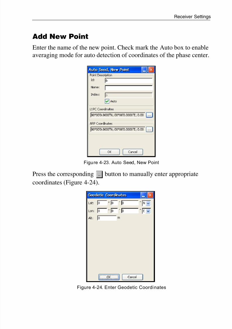
Add New Point
Enter the name of the new point. Check mark the Auto box to enable
averaging mode for auto detection of coordinates of the phase center.
Figure 4-23. Auto Seed, New Point
Press the corresponding button to manually enter appropriatecoordinates (Figure 4-24).
Figure 4-24. Enter Geodetic Coordinates
8/10/2019 7010-0980 - GRX Utility RM.pdf
http://slidepdf.com/reader/full/7010-0980-grx-utility-rmpdf 56/80
Receiver Managing
GRX Utility Reference Manual4-26
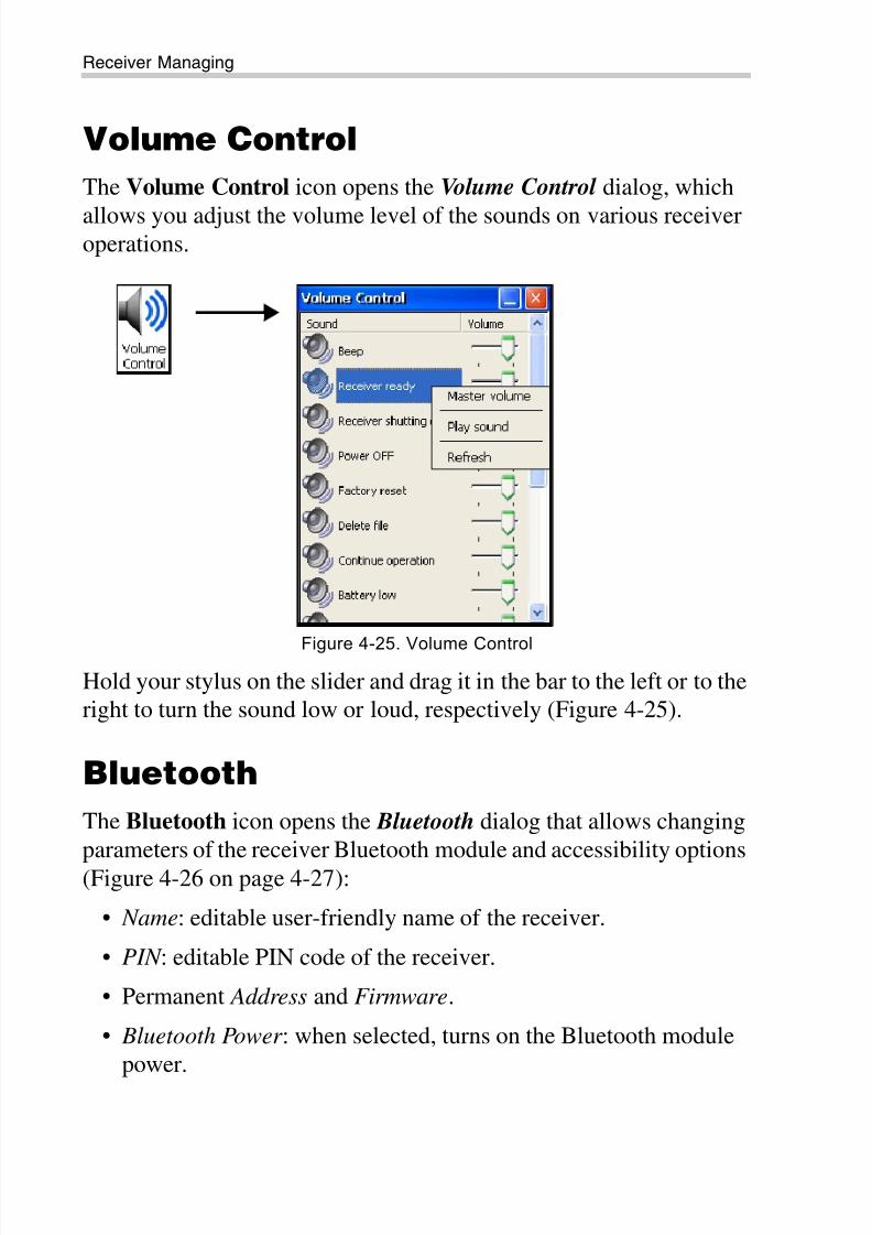
Volume Control
The Volume Control icon opens the Volume Control dialog, which
allows you adjust the volume level of the sounds on various receiveroperations.
Figure 4-25. Volume Control
Hold your stylus on the slider and drag it in the bar to the left or to the
right to turn the sound low or loud, respectively (Figure 4-25).
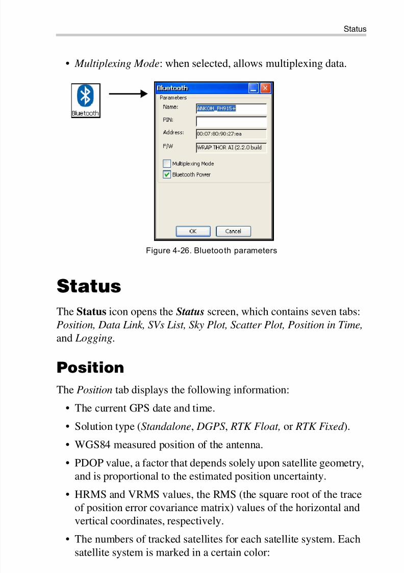
Bluetooth
The Bluetooth icon opens the Bluetooth dialog that allows changing
parameters of the receiver Bluetooth module and accessibility options
(Figure 4-26 on page 4-27):
• Name: editable user-friendly name of the receiver.
• PIN : editable PIN code of the receiver.
• Permanent Address and Firmware.
• Bluetooth Power : when selected, turns on the Bluetooth module
power.
8/10/2019 7010-0980 - GRX Utility RM.pdf
http://slidepdf.com/reader/full/7010-0980-grx-utility-rmpdf 57/80
Status
P/N 7010-0980 4-27
• Multiplexing Mode: when selected, allows multiplexing data.
Figure 4-26. Bluetooth parameters
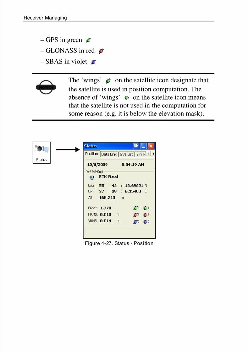
Status
The Status icon opens the Status screen, which contains seven tabs:
Position, Data Link, SVs List, Sky Plot, Scatter Plot, Position in Time,
and Logging.
Position
The Position tab displays the following information:
• The current GPS date and time.
• Solution type (Standalone, DGPS , RTK Float, or RTK Fixed ).
• WGS84 measured position of the antenna.
• PDOP value, a factor that depends solely upon satellite geometry,
and is proportional to the estimated position uncertainty.
• HRMS and VRMS values, the RMS (the square root of the trace
of position error covariance matrix) values of the horizontal and
vertical coordinates, respectively.
• The numbers of tracked satellites for each satellite system. Each
satellite system is marked in a certain color:
8/10/2019 7010-0980 - GRX Utility RM.pdf
http://slidepdf.com/reader/full/7010-0980-grx-utility-rmpdf 58/80
Receiver Managing
GRX Utility Reference Manual4-28
– GPS in green
– GLONASS in red
– SBAS in violet
Figure 4-27. Status - Posi tion
NOTICE
The ‘wings’ on the satellite icon designate that
the satellite is used in position computation. The
absence of ‘wings’ on the satellite icon means
that the satellite is not used in the computation for
some reason (e.g. it is below the elevation mask).
8/10/2019 7010-0980 - GRX Utility RM.pdf
http://slidepdf.com/reader/full/7010-0980-grx-utility-rmpdf 59/80
Status
P/N 7010-0980 4-29
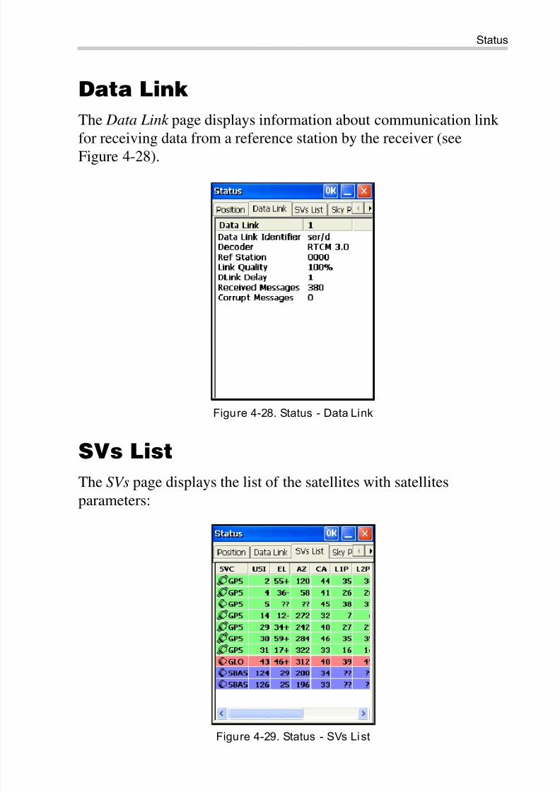
Data Link
The Data Link page displays information about communication link
for receiving data from a reference station by the receiver (seeFigure 4-28).
Figure 4-28. Status - Data Link
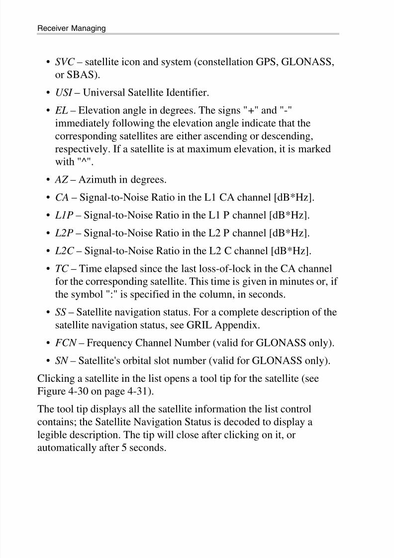
SVs List
The SVs page displays the list of the satellites with satellites
parameters:
Figure 4-29. Status - SVs List
8/10/2019 7010-0980 - GRX Utility RM.pdf
http://slidepdf.com/reader/full/7010-0980-grx-utility-rmpdf 60/80
Receiver Managing
GRX Utility Reference Manual4-30
• SVC – satellite icon and system (constellation GPS, GLONASS,
or SBAS).
• USI – Universal Satellite Identifier.• EL – Elevation angle in degrees. The signs "+" and "-"
immediately following the elevation angle indicate that the
corresponding satellites are either ascending or descending,
respectively. If a satellite is at maximum elevation, it is marked
with "^".
• AZ – Azimuth in degrees.
• CA – Signal-to-Noise Ratio in the L1 CA channel [dB*Hz].
• L1P – Signal-to-Noise Ratio in the L1 P channel [dB*Hz].
• L2P – Signal-to-Noise Ratio in the L2 P channel [dB*Hz].
• L2C – Signal-to-Noise Ratio in the L2 C channel [dB*Hz].
• TC – Time elapsed since the last loss-of-lock in the CA channel
for the corresponding satellite. This time is given in minutes or, if
the symbol ":" is specified in the column, in seconds.
• SS – Satellite navigation status. For a complete description of the
satellite navigation status, see GRIL Appendix.
• FCN – Frequency Channel Number (valid for GLONASS only).
• SN – Satellite's orbital slot number (valid for GLONASS only).
Clicking a satellite in the list opens a tool tip for the satellite (see
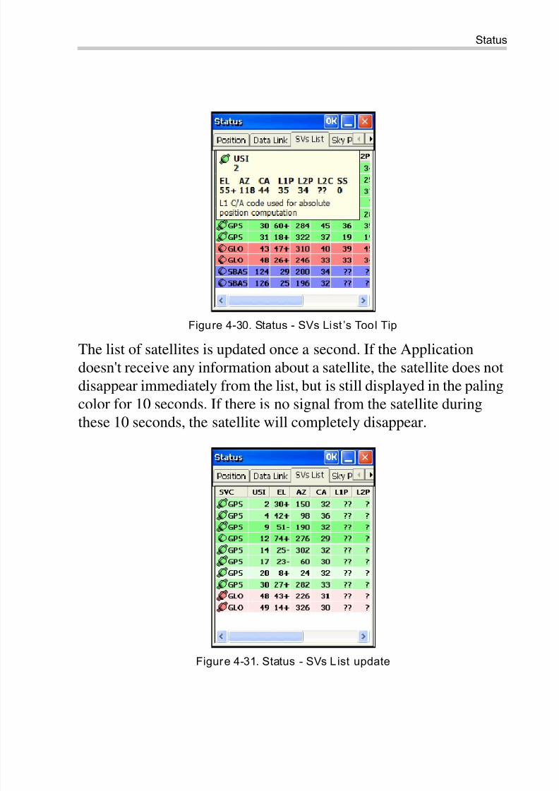
Figure 4-30 on page 4-31).
The tool tip displays all the satellite information the list control
contains; the Satellite Navigation Status is decoded to display a
legible description. The tip will close after clicking on it, or
automatically after 5 seconds.
8/10/2019 7010-0980 - GRX Utility RM.pdf
http://slidepdf.com/reader/full/7010-0980-grx-utility-rmpdf 61/80
Status
P/N 7010-0980 4-31
Figure 4-30. Status - SVs List ’s Tool Tip
The list of satellites is updated once a second. If the Application
doesn't receive any information about a satellite, the satellite does not
disappear immediately from the list, but is still displayed in the paling
color for 10 seconds. If there is no signal from the satellite during
these 10 seconds, the satellite will completely disappear.
Figure 4-31. Status - SVs L ist update
8/10/2019 7010-0980 - GRX Utility RM.pdf
http://slidepdf.com/reader/full/7010-0980-grx-utility-rmpdf 62/80
Receiver Managing
GRX Utility Reference Manual4-32
Sky Plot
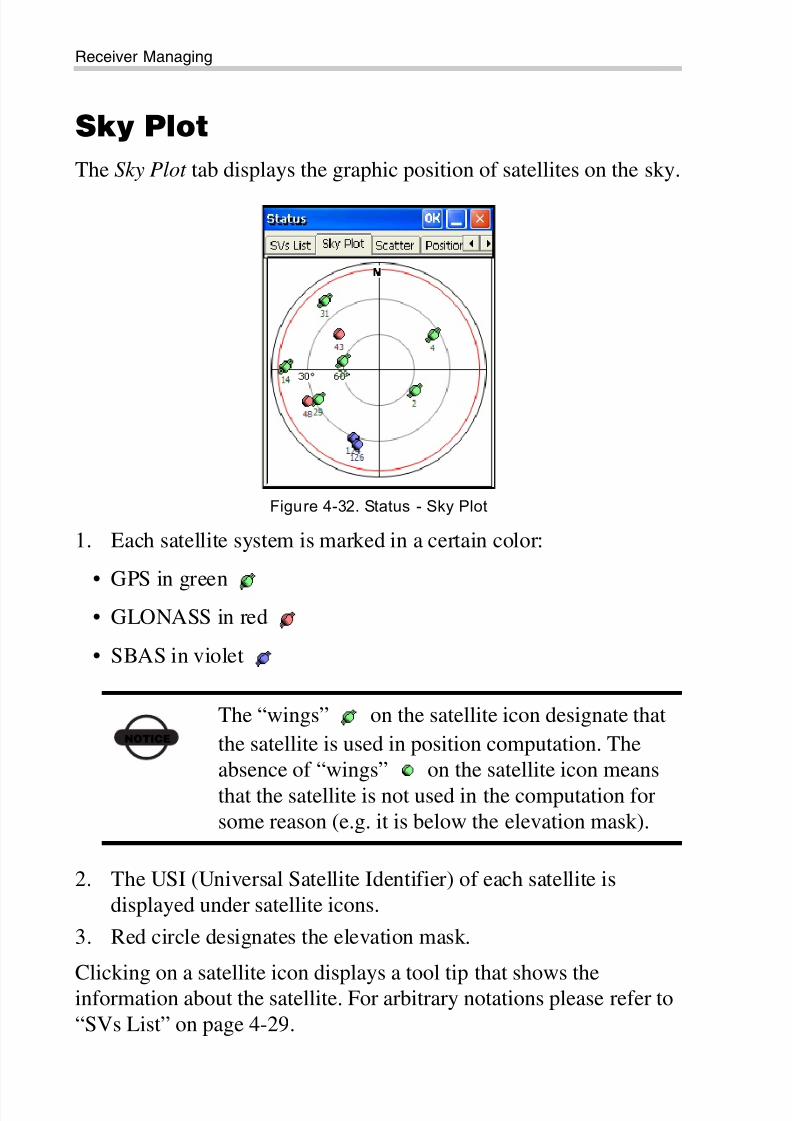
The Sky Plot tab displays the graphic position of satellites on the sky.
Figure 4-32. Status - Sky Plot
1. Each satellite system is marked in a certain color:
• GPS in green• GLONASS in red
• SBAS in violet
2. The USI (Universal Satellite Identifier) of each satellite is
displayed under satellite icons.
3. Red circle designates the elevation mask.
Clicking on a satellite icon displays a tool tip that shows theinformation about the satellite. For arbitrary notations please refer to
“SVs List” on page 4-29.
NOTICE
The “wings” on the satellite icon designate that
the satellite is used in position computation. The
absence of “wings” on the satellite icon means
that the satellite is not used in the computation for
some reason (e.g. it is below the elevation mask).
8/10/2019 7010-0980 - GRX Utility RM.pdf
http://slidepdf.com/reader/full/7010-0980-grx-utility-rmpdf 63/80
Status
P/N 7010-0980 4-33
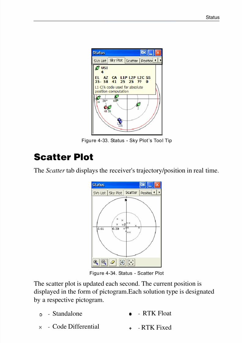
Figure 4-33. Status - Sky Plot ’s Tool Tip
Scatter Plot
The Scatter tab displays the receiver's trajectory/position in real time.
Figure 4-34. Status - Scatter Plot
The scatter plot is updated each second. The current position is
displayed in the form of pictogram.Each solution type is designated
by a respective pictogram.
- Standalone - RTK Float
- Code Differential - RTK Fixed
8/10/2019 7010-0980 - GRX Utility RM.pdf
http://slidepdf.com/reader/full/7010-0980-grx-utility-rmpdf 64/80
Receiver Managing
GRX Utility Reference Manual4-34
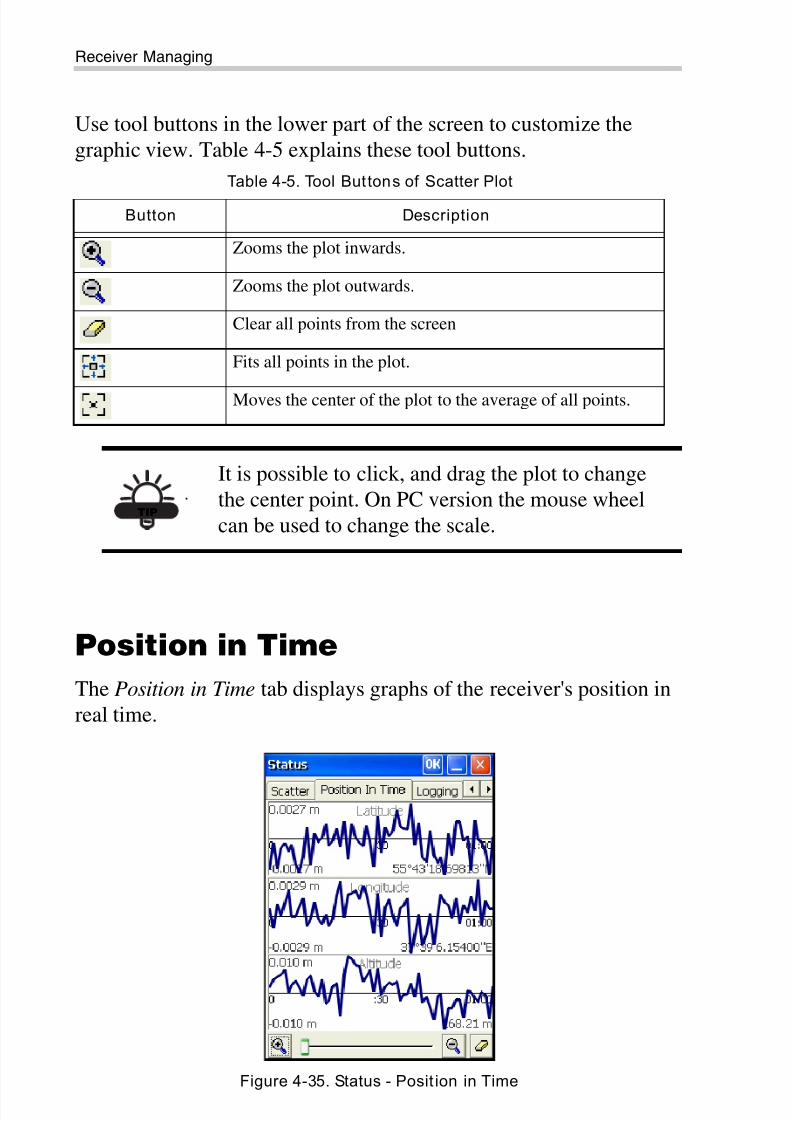
Use tool buttons in the lower part of the screen to customize the
graphic view. Table 4-5 explains these tool buttons.
Position in Time
The Position in Time tab displays graphs of the receiver's position in
real time.
Figure 4-35. Status - Posit ion in Time
Table 4-5. Tool Buttons of Scatter Plot
Button Description
Zooms the plot inwards.
Zooms the plot outwards.
Clear all points from the screen
Fits all points in the plot.
Moves the center of the plot to the average of all points.
TIP
It is possible to click, and drag the plot to change
the center point. On PC version the mouse wheel
can be used to change the scale.
8/10/2019 7010-0980 - GRX Utility RM.pdf
http://slidepdf.com/reader/full/7010-0980-grx-utility-rmpdf 65/80
Status
P/N 7010-0980 4-35
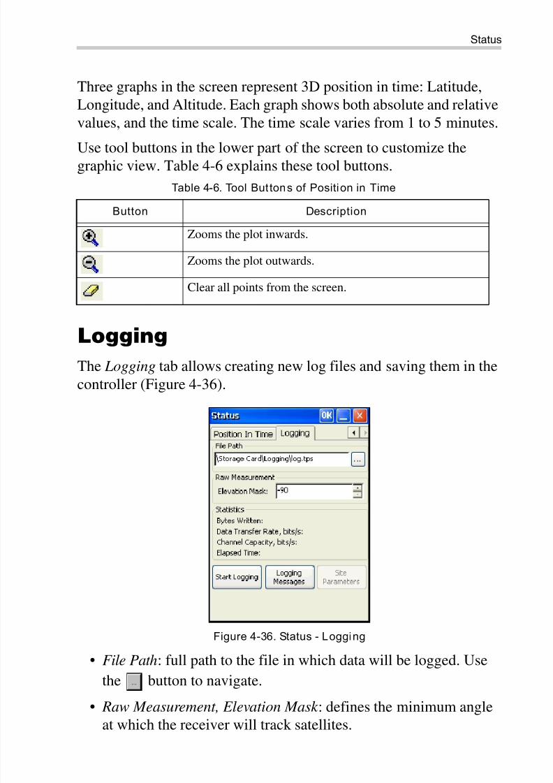
Three graphs in the screen represent 3D position in time: Latitude,
Longitude, and Altitude. Each graph shows both absolute and relative
values, and the time scale. The time scale varies from 1 to 5 minutes.
Use tool buttons in the lower part of the screen to customize the
graphic view. Table 4-6 explains these tool buttons.
Logging
The Logging tab allows creating new log files and saving them in the
controller (Figure 4-36).
Figure 4-36. Status - Logging
• File Path: full path to the file in which data will be logged. Use
the button to navigate.• Raw Measurement, Elevation Mask : defines the minimum angle
at which the receiver will track satellites.
Table 4-6. Tool Buttons of Position in Time
Button Description
Zooms the plot inwards.
Zooms the plot outwards.
Clear all points from the screen.
8/10/2019 7010-0980 - GRX Utility RM.pdf
http://slidepdf.com/reader/full/7010-0980-grx-utility-rmpdf 66/80
Receiver Managing
GRX Utility Reference Manual4-36
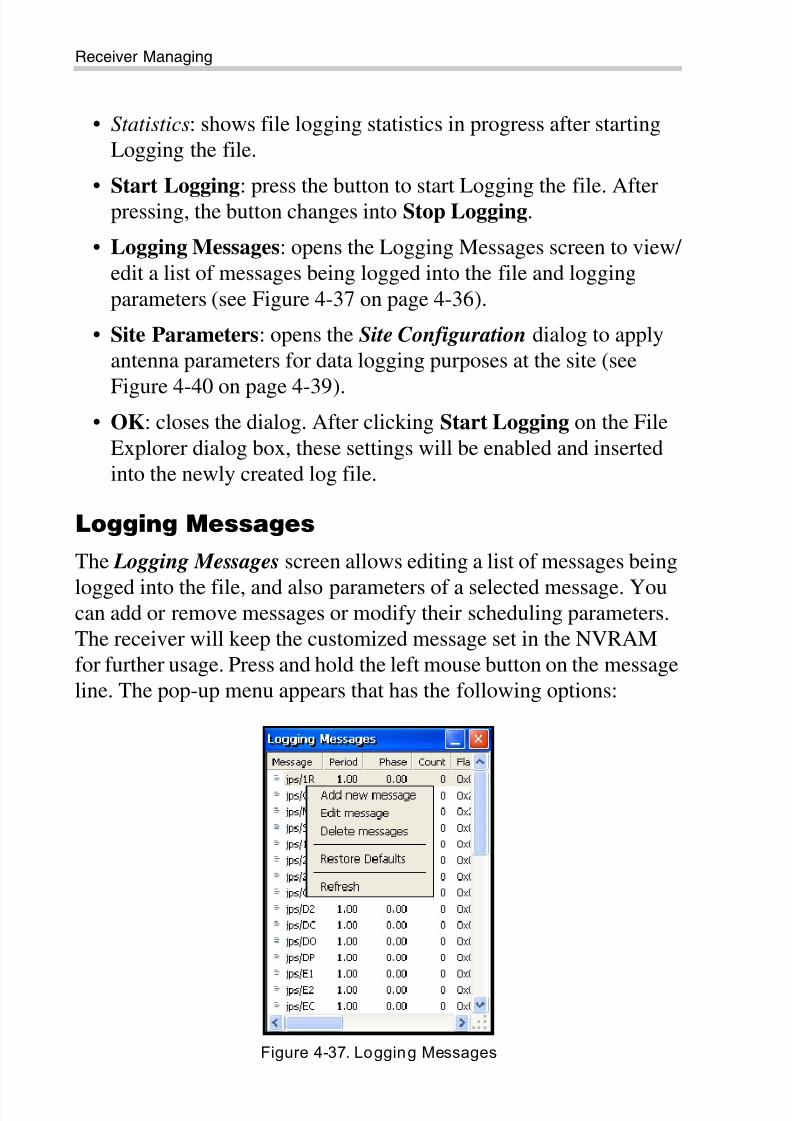
• Statistics: shows file logging statistics in progress after starting
Logging the file.
• Start Logging: press the button to start Logging the file. Afterpressing, the button changes into Stop Logging.
• Logging Messages: opens the Logging Messages screen to view/
edit a list of messages being logged into the file and logging
parameters (see Figure 4-37 on page 4-36).
• Site Parameters: opens the Site Configuration dialog to apply
antenna parameters for data logging purposes at the site (see
Figure 4-40 on page 4-39).• OK: closes the dialog. After clicking Start Logging on the File
Explorer dialog box, these settings will be enabled and inserted
into the newly created log file.
Logging Messages
The Logging Messages screen allows editing a list of messages being
logged into the file, and also parameters of a selected message. Youcan add or remove messages or modify their scheduling parameters.
The receiver will keep the customized message set in the NVRAM
for further usage. Press and hold the left mouse button on the message
line. The pop-up menu appears that has the following options:
Figure 4-37. Logging Messages
8/10/2019 7010-0980 - GRX Utility RM.pdf
http://slidepdf.com/reader/full/7010-0980-grx-utility-rmpdf 67/80
Status
P/N 7010-0980 4-37
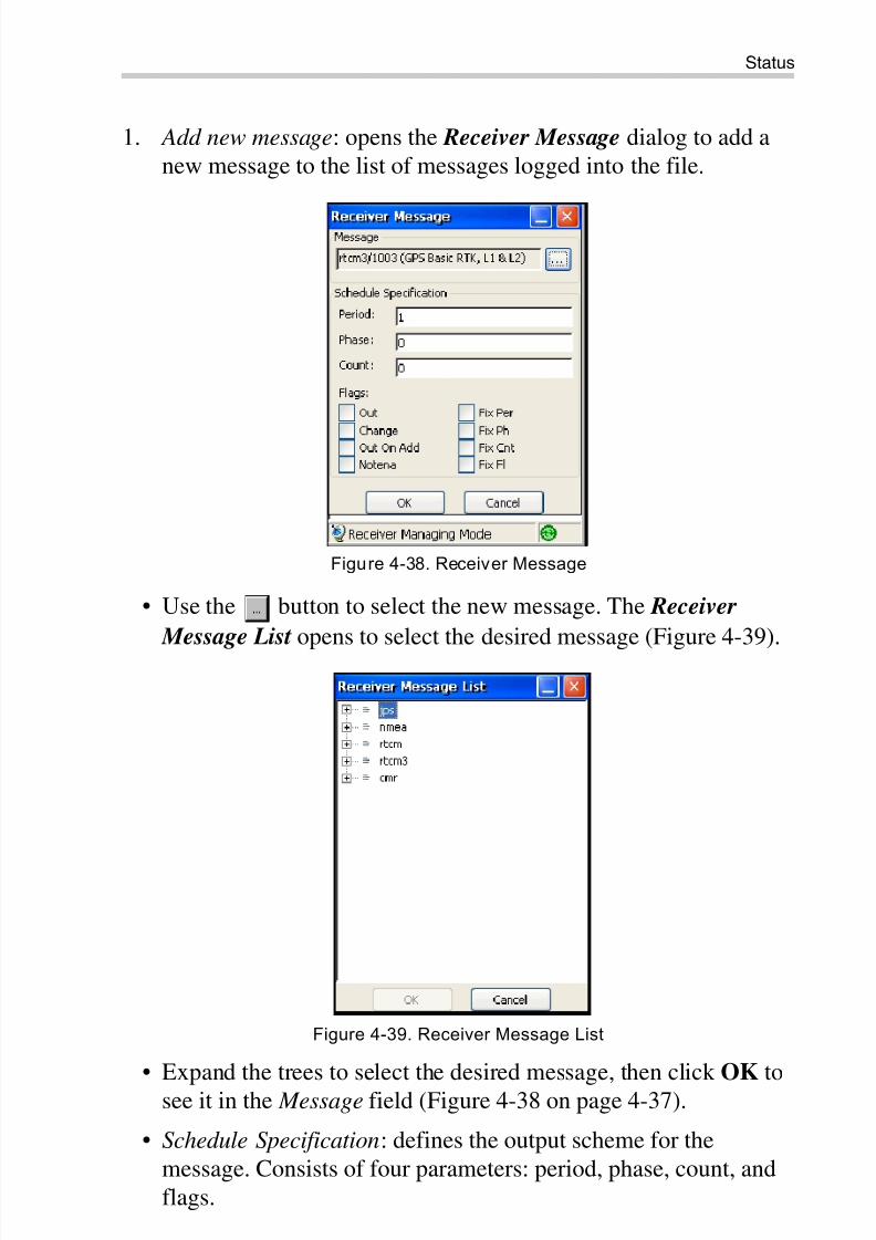
1. Add new message: opens the Receiver Message dialog to add a
new message to the list of messages logged into the file.
Figure 4-38. Receiver Message
• Use the button to select the new message. The Receiver
Message List opens to select the desired message (Figure 4-39).
Figure 4-39. Receiver Message List
• Expand the trees to select the desired message, then click OK to
see it in the Message field (Figure 4-38 on page 4-37).
• Schedule Specification: defines the output scheme for the
message. Consists of four parameters: period, phase, count, and
flags.
8/10/2019 7010-0980 - GRX Utility RM.pdf
http://slidepdf.com/reader/full/7010-0980-grx-utility-rmpdf 68/80
Receiver Managing
GRX Utility Reference Manual4-38
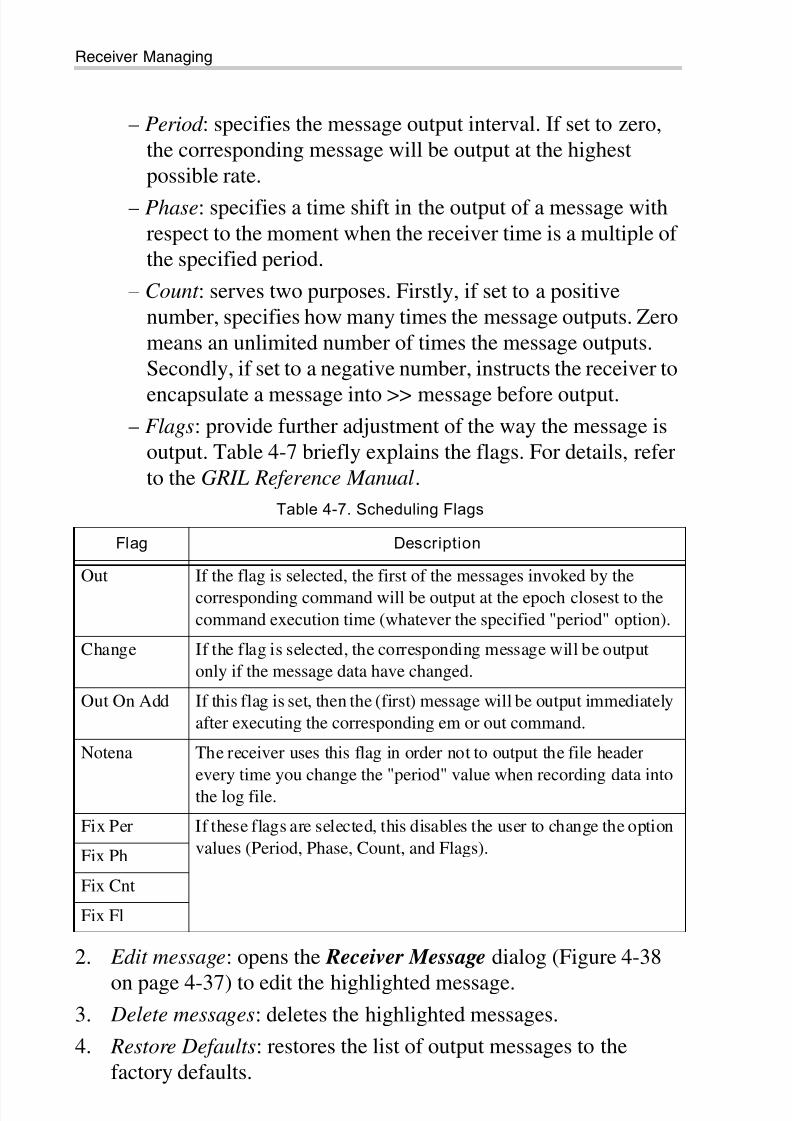
– Period : specifies the message output interval. If set to zero,
the corresponding message will be output at the highest
possible rate.
– Phase: specifies a time shift in the output of a message with
respect to the moment when the receiver time is a multiple of
the specified period.
– Count : serves two purposes. Firstly, if set to a positive
number, specifies how many times the message outputs. Zero
means an unlimited number of times the message outputs.
Secondly, if set to a negative number, instructs the receiver to
encapsulate a message into >> message before output.
– Flags: provide further adjustment of the way the message is
output. Table 4-7 briefly explains the flags. For details, refer
to the GRIL Reference Manual.
2. Edit message: opens the Receiver Message dialog (Figure 4-38
on page 4-37) to edit the highlighted message.3. Delete messages: deletes the highlighted messages.
4. Restore Defaults: restores the list of output messages to the
factory defaults.
Table 4-7. Scheduling Flags
Flag Description
Out If the flag is selected, the first of the messages invoked by the
corresponding command will be output at the epoch closest to the
command execution time (whatever the specified "period" option).
Change If the flag is selected, the corresponding message will be output
only if the message data have changed.
Out On Add If this flag is set, then the (first) message will be output immediately
after executing the corresponding em or out command.
Notena The receiver uses this flag in order not to output the file header
every time you change the "period" value when recording data into
the log file.
Fix Per If these flags are selected, this disables the user to change the option
values (Period, Phase, Count, and Flags).Fix Ph
Fix Cnt
Fix Fl
8/10/2019 7010-0980 - GRX Utility RM.pdf
http://slidepdf.com/reader/full/7010-0980-grx-utility-rmpdf 69/80
Status
P/N 7010-0980 4-39
5. Refresh: renews the list output messages with the last made
changes.
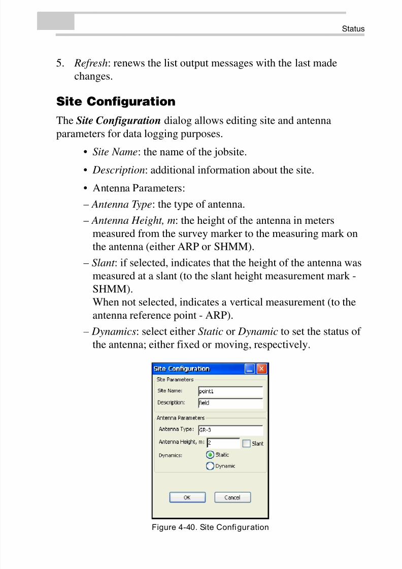
Site Configuration
The Site Configuration dialog allows editing site and antenna
parameters for data logging purposes.
• Site Name: the name of the jobsite.
• Description: additional information about the site.
• Antenna Parameters:
– Antenna Type: the type of antenna.
– Antenna Height, m: the height of the antenna in meters
measured from the survey marker to the measuring mark on
the antenna (either ARP or SHMM).
– Slant : if selected, indicates that the height of the antenna was
measured at a slant (to the slant height measurement mark -
SHMM).
When not selected, indicates a vertical measurement (to theantenna reference point - ARP).
– Dynamics: select either Static or Dynamic to set the status of
the antenna; either fixed or moving, respectively.
Figure 4-40. Site Configuration
8/10/2019 7010-0980 - GRX Utility RM.pdf
http://slidepdf.com/reader/full/7010-0980-grx-utility-rmpdf 70/80
Receiver Managing
GRX Utility Reference Manual4-40
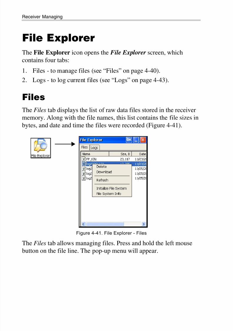
File Explorer
The File Explorer icon opens the File Explorer screen, which
contains four tabs:
1. Files - to manage files (see “Files” on page 4-40).
2. Logs - to log current files (see “Logs” on page 4-43).
Files
The Files tab displays the list of raw data files stored in the receiver
memory. Along with the file names, this list contains the file sizes inbytes, and date and time the files were recorded (Figure 4-41).
Figure 4-41. File Explorer - Files
The Files tab allows managing files. Press and hold the left mouse
button on the file line. The pop-up menu will appear.
8/10/2019 7010-0980 - GRX Utility RM.pdf
http://slidepdf.com/reader/full/7010-0980-grx-utility-rmpdf 71/80
File Explorer
P/N 7010-0980 4-41
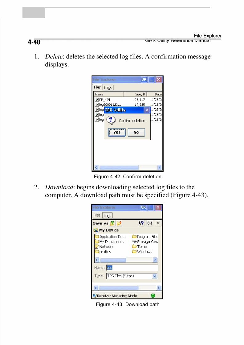
1. Delete: deletes the selected log files. A confirmation message
displays.
Figure 4-42. Confi rm deletion
2. Download : begins downloading selected log files to the
computer. A download path must be specified (Figure 4-43).
Figure 4-43. Download path
8/10/2019 7010-0980 - GRX Utility RM.pdf
http://slidepdf.com/reader/full/7010-0980-grx-utility-rmpdf 72/80
Receiver Managing
GRX Utility Reference Manual4-42
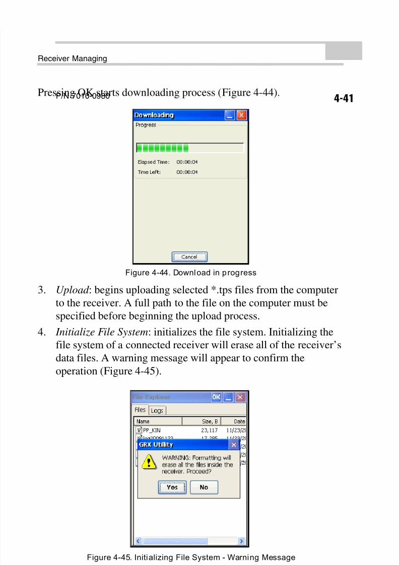
Pressing OK starts downloading process (Figure 4-44).
Figure 4-44. Download in progress
3. Upload : begins uploading selected *.tps files from the computer
to the receiver. A full path to the file on the computer must be
specified before beginning the upload process.
4. Initialize File System: initializes the file system. Initializing the
file system of a connected receiver will erase all of the receiver’s
data files. A warning message will appear to confirm the
operation (Figure 4-45).
Figure 4-45. Initializing File System - Warning Message
8/10/2019 7010-0980 - GRX Utility RM.pdf
http://slidepdf.com/reader/full/7010-0980-grx-utility-rmpdf 73/80
File Explorer
P/N 7010-0980 4-43
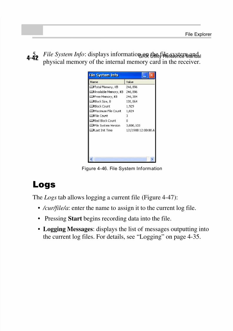
5. File System Info: displays information on the file system and
physical memory of the internal memory card in the receiver.
Figure 4-46. File System Information
Logs
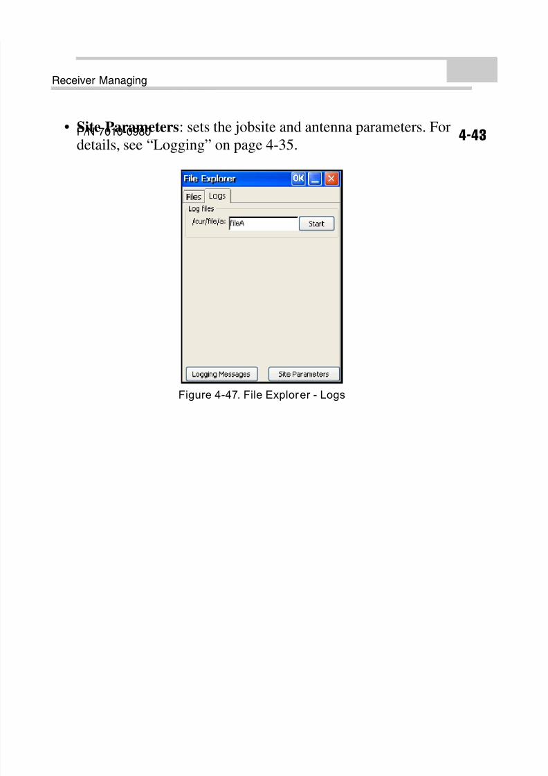
The Logs tab allows logging a current file (Figure 4-47):
• /cur/file/a: enter the name to assign it to the current log file.
• Pressing Start begins recording data into the file.
• Logging Messages: displays the list of messages outputting into
the current log files. For details, see “Logging” on page 4-35.
8/10/2019 7010-0980 - GRX Utility RM.pdf
http://slidepdf.com/reader/full/7010-0980-grx-utility-rmpdf 74/80
Receiver Managing
GRX Utility Reference Manual4-44
• Site Parameters: sets the jobsite and antenna parameters. For
details, see “Logging” on page 4-35.
Figure 4-47. File Explorer - Logs
8/10/2019 7010-0980 - GRX Utility RM.pdf
http://slidepdf.com/reader/full/7010-0980-grx-utility-rmpdf 75/80
P/N 7010-0980
Chapter 5
5-1
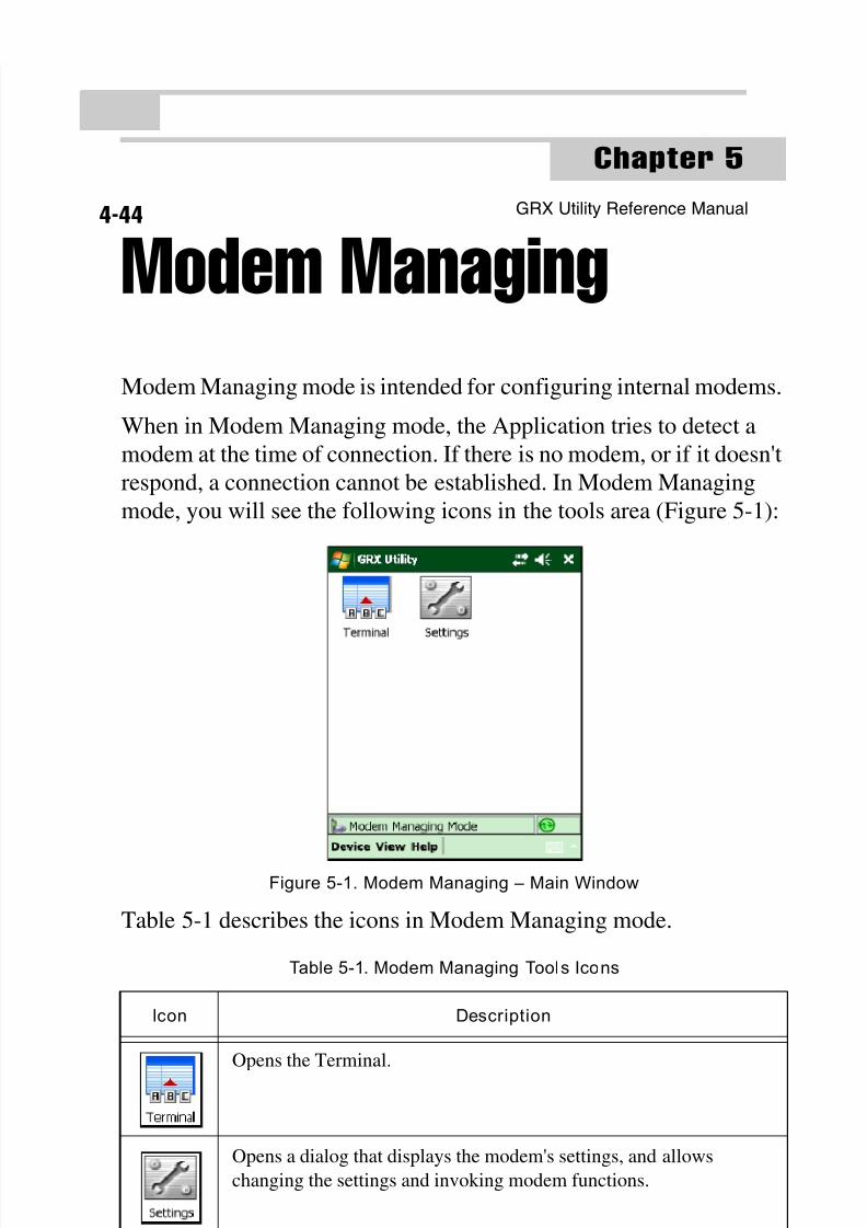
Modem ManagingModem Managing mode is intended for configuring internal modems.
When in Modem Managing mode, the Application tries to detect a
modem at the time of connection. If there is no modem, or if it doesn't
respond, a connection cannot be established. In Modem Managing
mode, you will see the following icons in the tools area (Figure 5-1):
Figure 5-1. Modem Managing – Main Window
Table 5-1 describes the icons in Modem Managing mode.
Table 5-1. Modem Managing Tools Icons
Icon Description
Opens the Terminal.
Opens a dialog that displays the modem's settings, and allows
changing the settings and invoking modem functions.
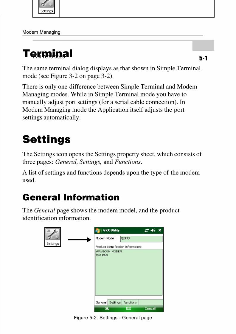
8/10/2019 7010-0980 - GRX Utility RM.pdf
http://slidepdf.com/reader/full/7010-0980-grx-utility-rmpdf 76/80
Modem Managing
GRX Utility Reference Manual5-2
Terminal
The same terminal dialog displays as that shown in Simple Terminal
mode (see Figure 3-2 on page 3-2).
There is only one difference between Simple Terminal and Modem
Managing modes. While in Simple Terminal mode you have to
manually adjust port settings (for a serial cable connection). In
Modem Managing mode the Application itself adjusts the port
settings automatically.
Settings
The Settings icon opens the Settings property sheet, which consists of
three pages: General, Settings, and Functions.
A list of settings and functions depends upon the type of the modem
used.
General Information
The General page shows the modem model, and the product
identification information.
Figure 5-2. Settings - General page
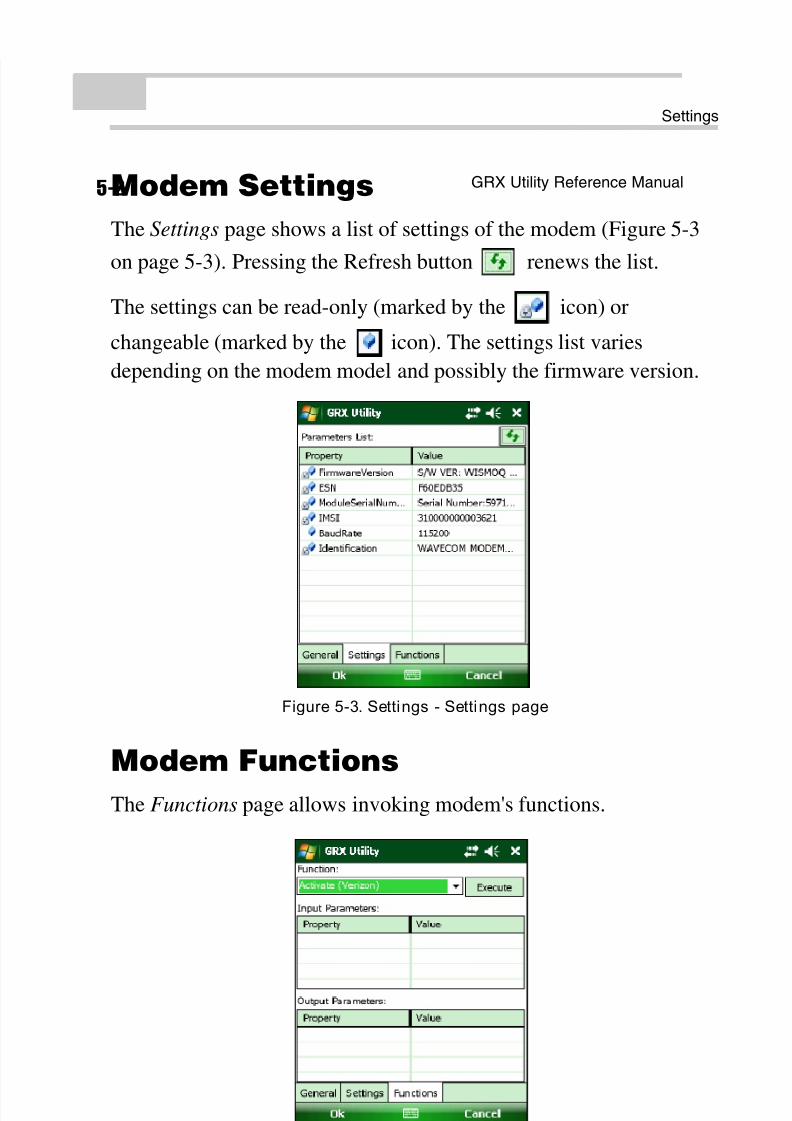
8/10/2019 7010-0980 - GRX Utility RM.pdf
http://slidepdf.com/reader/full/7010-0980-grx-utility-rmpdf 77/80
Settings
P/N 7010-0980 5-3
Modem Settings
The Settings page shows a list of settings of the modem (Figure 5-3
on page 5-3). Pressing the Refresh button renews the list.
The settings can be read-only (marked by the icon) or
changeable (marked by the icon). The settings list varies
depending on the modem model and possibly the firmware version.
Figure 5-3. Settings - Settings page
Modem Functions
The Functions page allows invoking modem's functions.
Figure 5-4. Settings - Functions page
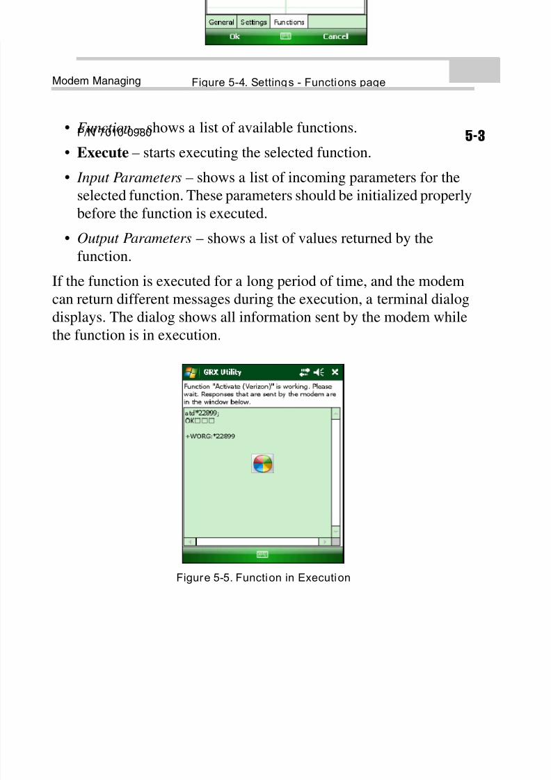
8/10/2019 7010-0980 - GRX Utility RM.pdf
http://slidepdf.com/reader/full/7010-0980-grx-utility-rmpdf 78/80
Modem Managing
GRX Utility Reference Manual5-4
• Function – shows a list of available functions.
• Execute – starts executing the selected function.
• Input Parameters – shows a list of incoming parameters for theselected function. These parameters should be initialized properly
before the function is executed.
• Output Parameters – shows a list of values returned by the
function.
If the function is executed for a long period of time, and the modem
can return different messages during the execution, a terminal dialog
displays. The dialog shows all information sent by the modem whilethe function is in execution.
Figure 5-5. Function in Execution

8/10/2019 7010-0980 - GRX Utility RM.pdf
http://slidepdf.com/reader/full/7010-0980-grx-utility-rmpdf 79/80

8/10/2019 7010-0980 - GRX Utility RM.pdf
http://slidepdf.com/reader/full/7010-0980-grx-utility-rmpdf 80/80
Recommended