- Engineered to save our customers money- Eliminate the belt and pulleys- EnergyefficientECMotor- Improve indoor air quality
• EnergyEfficient
• EasytoInstall
• ExtendedServiceLife
DirectDriveBlowerCoilsHDYANDVDYTECHNICALCATALOG
VDY
- Experience quieter operations- Reduce costs- NominalCFMrangeof600to3,000CFM
HDY

DirectDriveBlowerCoilsHDYANDVDYTECHNICALCATALOG
2
InternationalEnvironmentalCorporation(IEC)workscontinuallytoimproveitsproducts.Asaresult,thedesignandspecificationsofeachproductmaybechangedwithoutnoticeandmaynotbeasdescribedherein.PleasecontactIECforinformationregardingcurrentdesignandproductspecifications.StatementsandotherinformationcontainedhereinarenotexpresswarrantiesanddonotformthebasisofanybargainbetweenthepartiesbutaremerelyIEC’sopinionor commendationof itsproducts.Manufacturer’sstandardlimitedwarrantyapplies.

DirectDriveBlowerCoilsHDYANDVDYTECHNICALCATALOG
3
TableofContents
4-6 Features and Benefits
7-8 Unit Nomenclature
9 AHRI Nominal Capacity
10-15 Cooling Capacity
16-23 Heating Capacity
24 Static Resistance Table
25-26 Sound Power Data
27-30 Fan Curves – HDY
31-34 Fan Curves – VDY
35-38 Submittal Data
39-42 Piping Connections
43-44 Electric Heat
45 Motor Data
46-48 Factory Installed Options
49-50 Unit Weight Calculations
51-52 Filters
53-55 Mixing Boxes
56 Serial Plate Example

DirectDriveBlowerCoilsHDYANDVDYTECHNICALCATALOG
4
FeaturesandBenefitsDirectDriveBlowerCoilsMeettheVersatileNeedsofOurCustomerThesecompactblowercoilsareideallysuitedforavarietyofductedapplicationsthatrequirearangeof600to3000CFM,capacitiesbetween1.5tonsto9tons,andgenerallyratedforapplicationsupto2.25”w.goftotal static pressure. These units provide comfort cooling andheatingwhileofferingabroadrangeofapplicationflexibilitybetweenthetraditionalfancoilunitandacentralstationairhandlingunit.Severalconfigurationsare available to meet the needs of different climates and applications.
The Direct Drive units can be ordered as:
• 2-pipe system• 2-pipesystemwithelectricheat• 4-pipe system• Direct expansion system cooling• Directexpansioncoolingwithelectricheat• Directexpansioncoolingwithhotwaterheating
Direct Drive units are ceiling-mounted and available withavarietyofoptionsthatcanmeetthedesignrequirements,andprovidealowcostsolutionforamultitude of applications.
HDY/VDYareavailablewithleft-orright-handarrangementsfordesignflexibility.
DirectDriveBlowerCoilsHDYANDVDYTECHNICALCATALOG
5
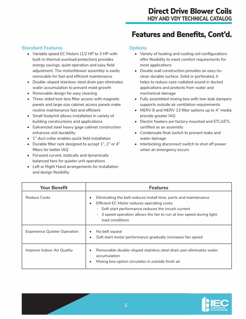
FeaturesandBenefits,Cont’d.Standard Features• VariablespeedECMotors(1/2HPto3HPwithbuilt-inthermaloverloadprotection)providesenergysavings,quietoperationandeasyfieldadjustment.Themotor/blowerassemblyiseasilyremovableforfastandefficientmaintenance
• Double-sloped stainless-steel drain pan eliminates wateraccumulationtopreventmoldgrowth
• Removable design for easy cleaning• Three-sidedtool-lessfilteraccesswithmagneticpanelsandlargesizecabinetaccesspanelsmakeroutinemaintenancefastandefficient.
• Smallfootprintallowsinstallationinvarietyofbuilding constructions and applications
• Galvanized steel heavy gage cabinet construction enhances unit durability
• 1”ductcollarenablesquickfieldinstallation• Durablefilterrackdesignedtoaccept1”,2”or4”filtersforbetterIAQ
• Forwardcurved,staticallyanddynamicallybalanced fans for quieter unit operations
• Left or Right Hand arrangements for installation anddesignflexibility
Options• Varietyofheatingandcoolingcoilconfigurationsofferflexibilitytomeetcomfortrequirementsformost applications
• Doublewallconstructionprovidesaneasy-to-cleandurablesurface.Solidorperforated,ithelps to reduce case-radiated sound in ducted applicationsandprotectsfromwaterandmechanical damage
• Fullyassembledmixingboxwithlow-leakdamperssupports outside air ventilation requirements
• MERV8andMERV13filteroptionsupto4”mediaprovidegreaterIAQ
• Electric heaters are factory mounted and ETL/cETL certifiedasanassembly
• Condensatefloatswitchtopreventleaksandwaterdamage
• Interlockingdisconnectswitchtoshutoffpowerwhenanemergencyoccurs
Your Benefit Features
ReduceCosts • Eliminatingthebeltreducesinstalltime,partsandmaintenance• EfficientECMotorreducesoperatingcosts:
-Softstartperformancereducestheinrushcurrent-3speedoperationallowsthefantorunatlowspeedduringlight load conditions
ExperienceQuieterOperation • No belt squeal• Softstartmotorperformancegraduallyincreasesfanspeed
ImproveIndoorAirQuality • Removabledouble-slopedstainlesssteeldrainpaneliminateswateraccumulation
• Mixingboxoptioncirculatesinoutsidefreshair

DirectDriveBlowerCoilsHDYANDVDYTECHNICALCATALOG
6
FeaturesandBenefits,Cont’d.ApplicationsWhere the application calls for cooling capacities or externalstaticpressuresthatcannotbemetwithstandard or high performance direct drive fan coil units; useanIECverticaldirectdriveblowercoil.
Application Fit• Horizontalconfiguration,with8differentsizes
meet a multitude of room layouts and ventilation needs
• Wide variety of coil options
Large Public AreasTheseunitsareidealforapplicationswithalargecommonareasuchasrestaurants,airports,sportsarenas,stadiums,privateboxes,gymnasiums,exerciseareas,lockerrooms,atriumsandfoyers,auditoriums,shoppingmalls,equipmentormechanicalrooms,andcasinos,tonameafew.
Quality and Safety• Every unit tested and inspected at the factory for
trouble-free startup• Optionalcondensatefloatswitch• Motorshavebuilt-inthermaloverloadprotection• OptionalInterlockingDisconnectSwitch• ETL and cETL listed
Operating LimitationsThefancurvesoutlinetheairflowandstaticpressurerangewhereitisacceptabletoruntheseunits.Onunitswithelectricheat,theminimumairflowshownon the operating envelope must be maintained to prevent electric heat nuisance trips.
Installation Considerations (Reference IOM for details)Horizontal units are generally suspended above the ceiling using hanger rods that go through the corner knock-outsprovidedintheunits.Attentionshouldbepaid to having enough clearance around the units for service and maintenance. External vibration isolation andflexconnectionsforductsarerecommended.
Acoustical Considerations With sound becoming more of a concern to design engineers,buildingownersandoccupants,properconsideration should be given to the selection and placement of these units. To further reduce the soundlevel,additionalmeasurescanbetaken.Someexamples include:• Usingflexibleductconnectors• Liningthemainsupplyandreturnductswith
acoustical absorption material• Placingthereturnairgrillesasfarawayfromthe
unit as possible.

DirectDriveBlowerCoilsHDYANDVDYTECHNICALCATALOG
7
UnitNomenclature UNIT SIZE06 • 600CFM08 • 800CFM10 • 1000CFM12 • 1200CFM16 • 1600CFM20 • 2000CFM22 • 2200CFM30 • 3000CFM
CABINET OPTIONSDrain PanAS • DoubleSlopeStainlessSteel
Filter OptionsC • 2setsof1”throwawayF • 1”PleatedMERV8G • 2”PleatedMERV8M • 2”MERV11with2”pleatedpre-filterU • 4”MERV11W • 4”MERV13
InsulationC* • 1”ClosedCellW • 1”StandardFiberglassS* • 1”PremiumIAQFiberglass(EdgesSealed)G* • 1”FoilFace(EdgesSealed)
*C, S & G not allowable w/ Double-Wall
Mixing BoxN • Rear&BottomReturncomesStandardwith Single-bladeDampers
Walls ConstructionY • Single-Wall(Standard)A • Double-WallConstruction(SolidLiner)B • DWConstr.(Perforated)
Other Cabinet OptionsA • Cabinet/ControlBoxServiceLight
COILRowsBY • 4KY • 6LY • 8B6 • 4/1B7 • 4/2K6 • 6/1K • 6/2QY • 4rowDX410AFY • 6RowDX410A
Onsize16andabovewith1rowheatcoilis2circuit,belowsize16coilhas1circuit
Total rows allowed is 8. HandR • Right-handCoilConnectionsL • Left-handCoilConnections
Standing in front of the unit, hand is determined by looking into the air supply and assigning the hand to match the location of the cooling coil connections.
Material (Tube/Fin/Coatings)Y • AluminumFinsw/GalvanizedWrapS • AluminumFinsw/StainlessSteelWrapC • CopperFinsStainlessSteelWrap
Accessories - Vents/DrainsY • MAV(Std)A • AAV(2-Pipe)B • AAV(4-Pipe)C • MAVw/Drain(2-Pipe)D • MAVw/Drain(4-Pipe)E • AAVw/Drain(2-Pipe)F • AAVw/Drain(4-Pipe)
Accessories - TXV T • TXVValve(DXOnly)Y • None

DirectDriveBlowerCoilsHDYANDVDYTECHNICALCATALOG
8
UnitNomenclature,Cont’d. EC MOTORMotor-Voltage/Phase/HertzC • 115/1/50-60D • 208/1/50-60E • 230/1/50-60F • 277/1/50-60V • 220/1/50N • 208/3/50-60P • 230/3/50-60G • 460/3/50-60
HorsepowerC • 1/2HPE • 1HPF • 1.5HP(ThreePhaseonly)H • 3HP(ThreePhaseonly)
Motor TypeM • ECMotor,noboard(0-10VDC)N • ECMotor,POTboard,3discretespeeds ELECTRIC HEATHeater VoltageY • None F • 277/1/60C • 120/1/60 N • 208/3/60D • 208/1/60 P • 240/3/60E • 240/1/60 G • 480/3/60
Heater KilowattY • NoneBY • 1.0 HY • 5 NH • 15CY • 1.5 JY • 6 NJ • 16DY • 2 KY • 7 NL • 18EY • 2.5 LY • 8 RY • 19.9FY • 3 NY • 9.9 RH • 25FA • 3.5 PY • 12 SY • 30GY • 4 QY • 14GA • 4.5
Note: Voltage rules required , motor & heater voltage must match. Dual power source is not available.
Heater StagesY • NoneA • 1-Stage,Single-Phase(1-12kW)B • 2-Stage,Single-Phase(3-12kW)C • 1-Stage,3-Phase(1-35kW)D • 2-Stage,3-Phase(4-35kW)E • 3-Stage,3-Phase(12-35kW)
Rules apply for stages
CONTROLSApplicationsBA1Y BP1KBA3Y BP1HBA1J BP1LBA3J BP3KBP1R BP3HBP3R BP3L
1st DigitisControlVoltageB=24 volt2nd DigitisTypeofControlA=MotorControls P=ElectricHeat&MotorControlsThird Digit is Phase 1=SinglePhase 3=3Phase4th DigitisFusingandDisconnectY=Std24VControlFusingandNoDisconnectJ=Yplus40ampDisconnect;R=Std.24VControlFusingandHeaterFusing,NoDisconnectK=Rplus40ampDisconnectH=Rplus60ampDisconnectL=Rplus80ampDisconnect(All electric heat includes thermal limit switch)
Special ControlsO • CondensateOverflowSwitch
Low Voltage PackageV • 3-SpeedAdjustable(Default)W • Proportional(requires0-10VDCcontroller)
THERMOSTAT CONTROLSN • Basic24VDigital,Non-programmableP • Basic24VDigital,7-DayProgrammableW • Venture24VWi-FiProgrammable

DirectDriveBlowerCoilsHDYANDVDYTECHNICALCATALOG
9
AHRINominalCapacityC-ETL-US ListingIEC’sDirectDriveBlowerCoilunitsarelistedbyIntertekTestingServices(ITS).ITS’sC-ETL-USlistingsignifiesthatIEC’sblowercoilunitshavebeen examined byITSandcomplywiththeminimumrequirementsofU.S.andCanadiannationalproductsafetystandard,UL1995/CSAC22.2No.236,andthatIEC’smanufacturingsitehasbeenaudited.ITS’sre-examinationserviceincludesperiodicvisitstoIEC’sfactorytoensurecontinuedcomplianceforall listed products
AHRI CertificationIEC’sDirectDriveBlowerCoilunitsarecertifiedincompliancewithAir-Conditioning,Heating,andRefrigerationInstitute(AHRI)industrystandardAHRI-440forroomfancoilunits.Approvedstandardratingsaretabulatedbelow.
3061627HEATING AND COOLING EQUIPMENT
Nominal Capacity Range – HDY
Model Unit Size
Coil Rows
Nominal CFM
Water Pressure
Drop (ft. water)
Cooling Capacity1 (BTUH) Power
Input (Watts)Total Sensible
HDY
06 4 600 1.8 19,900 13,800 85
06 6 600 3.8 25,000 16,000 120
06 8 600 4.8 26,000 16,000 120
08 4 800 2.9 24,900 17,800 160
08 6 800 5.5 31,000 20,100 175
08 8 800 8.4 34,800 21,200 205
10 4 1,000 5.7 33,700 23,200 220
10 6 1,000 10.7 40,500 25,900 240
10 8 1,000 15.9 45,100 27,500 260
12 4 1,200 7.2 38,400 26,800 335
12 6 1,200 14.7 47,600 30,700 350
12 8 1,200 20.5 52,000 31,800 380
16 4 1,600 4.7 49,000 35,300 410
16 6 1,600 10.0 61,500 39,700 420
16 8 1,600 14.2 67,100 41,400 520
20 4 2,000 5.5 62,100 45,000 445
20 6 2,000 11.2 78,000 51,300 465
20 8 2,000 17.0 87,400 55,400 510
22 4 2,200 8.0 65,000 47,200 575
22 6 2,200 15.0 83,800 54,900 600
22 8 2,200 23.0 95,500 59,000 660
30 4 3,000 6.1 98,500 71,100 790
30 6 3,000 10.7 123,900 80,400 860
30 8 3,000 18.4 140,000 88,500 890
Model Unit Size
Coil Rows
Nominal CFM
Water Pressure
Drop (ft. water)
Cooling Capacity1 (BTUH) Power
Input (Watts)Total Sensible
VDY
06 4 600 1.5 14,900 11,400 90
06 6 600 2.8 18,000 12,700 125
06 8 600 4.0 18,600 12,700 125
08 4 800 2.0 19,300 15,000 170
08 6 800 4.0 23,600 16,800 185
08 8 800 6.0 25,100 17,100 215
10 4 1,000 5.0 29,300 21,900 230
10 6 1,000 9.0 34,200 24,000 255
10 8 1,000 13.0 35,600 24,200 275
12 4 1,200 5.8 33,500 25,600 355
12 6 1,200 11.4 40,000 28,400 370
12 8 1,200 17.0 42,700 29,200 400
16 4 1,600 3.5 42,200 32,200 435
16 6 1,600 7.6 52,900 37,200 445
16 8 1,600 11.8 58,100 39,400 550
20 4 2,000 4.3 54,200 41,000 478
20 6 2,000 9.2 68,900 48,000 490
20 8 2,000 15.0 77,800 51,900 540
22 4 2,200 4.8 58,100 44,400 605
22 6 2,200 10.5 74,600 52,300 630
22 8 2,200 17.3 85,000 56,900 695
30 4 3,000 4.0 83,000 63,900 830
30 6 3,000 9.8 111,500 77,900 905
30 8 3,000 16.8 131,400 86,800 935NOTES:1. Ratingsarebasedon80°F(26.7°C)DBand67°F(19.4°C)WBEAT,45°F(7.2°C)EWT,10°FΔ(5.6°CΔ)watertemperaturerise,highfanspeed,motorvoltage115-1-60,and
airflowunderdrycoilconditions. 2. Forallapplicationratings,useIEC’scomputerselectionprogram,thequick-selectionratingsprovidedinthiscatalog,orcontactyourlocalIECrepresentative. 3. Foradditionalinformation,pleaseconsultAHRI’swebsiteatwww.ahrinet.org.
Nominal Capacity Range – VDY

DirectDriveBlowerCoilsHDYANDVDYTECHNICALCATALOG
10
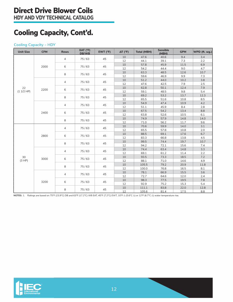
CoolingCapacity
NOTES:1. Ratingsarebasedon75°F(23.9°C)DBand63°F(17.2°C)WBEAT,45°F(7.2°C)EWT,10°FΔ(5.6°CΔ)or12°F(6.7°CΔ)watertemperaturerise. 2. WPD=Water Pressure Drop
Cooling Capacity – HDY
Unit Size CFM Rows EAT (°F)DB/WB EWT (°F) ΔT (°F) Total (MBH) Sensible
(MBH) GPM WPD (ft. wg.)
06(1/2HP)
500
4 75/63 4510 12.5 10.6 2.5 1.012 11.1 10.0 1.8 0.6
6 75/63 4510 15.3 11.9 3.0 2.012 14.0 11.4 2.3 1.3
8 75/63 4510 16.7 12.6 3.3 3.112 15.5 12.0 2.6 2.1
600
4 75/63 4510 14.6 12.5 2.9 1.212 13.1 11.9 2.2 0.8
6 75/63 4510 18.1 14.2 3.6 2.612 16.7 13.6 2.8 1.7
8 75/63 4510 20.0 15.1 4.0 4.112 18.6 14.5 3.1 2.7
700
4 75/63 4510 16.6 14.3 3.3 1.512 15.1 13.7 2.5 1.0
6 75/63 4510 20.8 16.4 4.1 3.312 19.2 15.8 3.2 2.2
8 75/63 4510 23.2 17.6 4.6 5.212 21.7 16.9 3.6 3.5
08(1HP)
700
4 75/63 4510 16.6 14.3 3.3 1.512 15.1 13.7 2.5 1.0
6 75/63 4510 20.8 16.4 4.1 3.312 19.2 15.8 3.2 2.2
8 75/63 4510 23.2 17.6 4.6 5.212 21.7 16.9 3.6 3.5
800
4 75/63 4510 18.5 16.2 3.7 1.812 16.9 15.5 2.8 1.2
6 75/63 4510 23.4 18.7 4.6 3.912 21.8 18.0 3.6 2.6
8 75/63 4510 26.3 20.1 5.2 6.312 24.7 19.3 4.1 4.3
900
4 75/63 4510 20.4 17.9 4.0 2.112 18.6 17.2 3.1 1.4
6 75/63 4510 25.9 20.8 5.1 4.612 24.2 20.1 4.0 3.1
8 75/63 4510 29.4 22.5 5.8 7.512 27.6 21.7 4.6 5.1
10(1/2HP)
900
4 75/63 4510 22.6 18.6 4.5 3.112 20.8 17.9 3.4 2.0
6 75/63 4510 27.0 20.9 5.3 6.112 25.2 20.1 4.2 4.1
8 75/63 4510 28.3 21.5 5.6 8.812 26.6 20.7 4.4 6.0
1000
4 75/63 4510 24.7 20.4 4.9 3.512 22.8 19.7 3.8 2.3
6 75/63 4510 29.6 23.0 5.9 7.112 27.8 22.2 4.6 4.8
8 75/63 4510 31.4 23.9 6.2 10.412 29.5 23.1 4.9 7.1
1100
4 75/63 4510 26.7 22.3 5.3 4.012 24.7 21.5 4.1 2.6
6 75/63 4510 32.4 25.2 6.4 8.212 30.4 24.4 5.0 5.5
8 75/63 45 10 34.4 26.2 6.8 12.012 32.5 25.4 5.4 8.2

DirectDriveBlowerCoilsHDYANDVDYTECHNICALCATALOG
11
CoolingCapacity,Cont’d.
NOTES:1. Ratingsarebasedon75°F(23.9°C)DBand63°F(17.2°C)WBEAT,45°F(7.2°C)EWT,10°FΔ(5.6°CΔ)or12°F(6.7°CΔ)watertemperaturerise.
Cooling Capacity – HDY
Unit Size CFM Rows EAT (°F)DB/WB EWT (°F) ΔT (°F) Total (MBH) Sensible
(MBH) GPM WPD (ft. wg.)
12(1HP)
1100
4 75/63 4510 26.7 22.3 5.3 4.012 24.7 21.5 4.1 2.6
6 75/63 4510 32.4 25.2 6.4 8.212 30.4 24.4 5.0 5.5
8 75/63 4510 34.4 26.2 6.8 12.012 32.5 25.4 5.4 8.2
1200
4 75/63 4510 28.7 24.1 5.7 4.512 26.7 23.3 4.4 3.0
6 75/63 4510 35.0 27.4 6.9 9.212 32.8 26.5 5.4 6.2
8 75/63 4510 37.5 28.6 7.4 13.812 35.4 27.7 5.8 9.4
1300
4 75/63 4510 30.6 25.9 6.1 4.912 28.5 25.0 4.7 3.3
6 75/63 4510 37.5 29.5 7.4 10.312 35.4 28.6 5.8 7.0
8 75/63 4510 40.4 30.9 8.0 15.512 38.2 30.0 6.3 10.6
16(1HP)
1400
4 75/63 4510 32.1 27.7 6.4 2.312 29.4 26.6 4.9 1.5
6 75/63 4510 37.9 30.6 7.5 4.512 35.4 29.6 5.9 3.0
8 75/63 4510 40.3 31.7 8.0 6.612 37.8 30.6 6.2 4.5
1600
4 75/63 4510 36.0 31.3 7.1 2.712 33.2 30.2 5.5 1.8
6 75/63 4510 42.9 34.9 8.5 5.412 40.3 33.8 6.7 3.7
8 75/63 4510 46.0 36.3 9.1 8.112 43.3 35.1 7.2 5.5
1800
4 75/63 4510 39.8 34.9 7.9 3.212 36.8 33.7 6.1 2.1
6 75/63 4510 47.6 39.0 9.4 6.412 44.9 37.9 7.4 4.4
8 75/63 4510 51.5 40.8 10.2 9.712 48.8 39.7 8.1 6.7
20(1HP)
1800
4 75/63 4510 43.8 37.1 8.7 3.012 40.4 35.7 6.7 1.9
6 75/63 4510 52.7 41.6 10.4 6.012 49.4 40.2 8.2 4.1
8 75/63 4510 57.1 43.7 11.3 9.112 53.9 42.3 8.9 6.2
2000
4 75/63 4510 47.6 40.6 9.4 3.412 44.1 39.1 7.3 2.2
6 75/63 4510 57.8 45.9 11.5 6.912 54.2 44.4 9.0 4.7
8 75/63 4510 63.3 48.5 12.6 10.712 59.6 46.9 9.9 7.3
2200
4 75/63 4510 51.2 44.0 10.2 3.812 47.6 42.5 7.9 2.5
6 75/63 4510 62.8 50.1 12.4 7.912 59.1 48.5 9.8 5.4
8 75/63 45 10 69.2 53.2 13.7 12.312 65.5 51.6 10.8 8.5
DirectDriveBlowerCoilsHDYANDVDYTECHNICALCATALOG
12
CoolingCapacity,Cont’d.Cooling Capacity – HDY
NOTES:1. Ratingsarebasedon75°F(23.9°C)DBand63°F(17.2°C)WBEAT,45°F(7.2°C)EWT,10°FΔ(5.6°CΔ)or12°F(6.7°CΔ)watertemperaturerise.
Unit Size CFM Rows EAT (°F)DB/WB EWT (°F) ΔT (°F) Total (MBH) Sensible
(MBH) GPM WPD (ft. wg.)
22(11/2HP)
2000
4 75/63 4510 47.6 40.6 9.4 3.412 44.1 39.1 7.3 2.2
6 75/63 4510 57.8 45.9 11.5 6.912 54.2 44.4 9.0 4.7
8 75/63 4510 63.3 48.5 12.6 10.712 59.6 46.9 9.9 7.3
2200
4 75/63 4510 51.2 44.0 10.2 3.812 47.6 42.5 7.9 2.5
6 75/63 4510 62.8 50.1 12.4 7.912 59.1 48.5 9.8 5.4
8 75/63 4510 69.2 53.2 13.7 12.312 65.5 51.6 10.8 8.5
2400
4 75/63 4510 54.9 47.4 10.9 4.212 51.1 45.9 8.4 2.8
6 75/63 4510 67.5 54.2 13.4 8.812 63.8 52.6 10.5 6.1
8 75/63 4510 74.9 57.9 14.8 14.012 71.0 56.2 11.7 9.6
30(3HP)
2800
4 75/63 4510 70.6 59.9 14.0 3.112 65.5 57.8 10.8 2.0
6 75/63 4510 88.5 69.1 17.6 6.712 83.3 66.8 13.8 4.5
8 75/63 4510 99.5 74.4 19.7 10.712 94.2 72.1 15.6 7.4
3000
4 75/63 4510 74.4 63.4 14.8 3.312 69.1 61.2 11.4 2.2
6 75/63 4510 93.5 73.3 18.5 7.212 88.1 71.0 14.6 4.9
8 75/63 4510 105.5 79.2 20.9 11.812 100.0 76.8 16.5 8.1
3200
4 75/63 4510 78.1 66.9 15.5 3.612 72.7 64.6 12.0 2.4
6 75/63 4510 98.3 77.5 19.5 7.812 92.9 75.2 15.3 5.4
8 75/63 45 10 111.1 83.8 22.0 12.812 105.6 81.4 17.5 8.8

DirectDriveBlowerCoilsHDYANDVDYTECHNICALCATALOG
13
CoolingCapacity,Cont’d.
NOTES:1. Ratingsarebasedon75°F(23.9°C)DBand63°F(17.2°C)WBEAT,45°F(7.2°C)EWT,10°FΔ(5.6°CΔ)or12°F(6.7°CΔ)watertemperaturerise.
Cooling Capacity – VDY
Unit Size CFM Rows EAT (°F)DB/WB EWT (°F) ΔT (°F) Total (MBH) Sensible
(MBH) GPM WPD (ft. wg.)
06(1/2HP)
500
4 75/63 4510 9.1 8.2 1.8 0.612 8.5 8.0 1.4 0.4
6 75/63 4510 10.6 8.8 2.1 1.112 9.6 8.3 1.6 0.7
8 75/63 4510 10.5 8.4 2.1 1.512 9.5 8.0 1.6 1.0
600
4 75/63 4510 11.0 9.9 2.2 0.812 9.8 9.4 1.6 0.5
6 75/63 4510 12.8 10.6 2.5 1.512 11.5 10.0 1.9 1.0
8 75/63 4510 12.9 10.3 2.6 2.112 11.6 9.8 1.9 1.3
700
4 75/63 4510 12.8 11.5 2.5 1.012 11.3 10.9 1.9 0.6
6 75/63 4510 14.9 12.4 3 1.912 13.5 11.8 2.2 1.2
8 75/63 4510 15.3 12.2 3 2.712 13.9 11.6 2.3 1.7
08(1HP)
700
4 75/63 4510 12.8 11.5 2.5 1.012 11.3 10.9 1.9 0.6
6 75/63 4510 14.9 12.4 3 1.912 13.5 11.8 2.2 1.2
8 75/63 4510 15.3 12.2 3 2.712 13.9 11.6 2.3 1.7
800
4 75/63 4510 14.5 13.0 2.9 1.212 12.9 12.4 2.1 0.8
6 75/63 4510 17.1 14.2 3.4 2.412 15.5 13.5 2.6 1.5
8 75/63 4510 17.6 14.1 3.5 3.412 16.1 13.4 2.7 2.2
900
4 75/63 4510 16.2 14.6 3.2 1.412 14.5 13.9 2.4 0.9
6 75/63 4510 19.2 15.9 3.8 2.912 17.5 15.2 2.9 1.9
8 75/63 4510 20.0 15.9 4 4.112 18.3 15.2 3 2.7
10(1/2HP)
900
4 75/63 4510 20.3 17.3 4 2.612 18.7 16.6 3.1 1.7
6 75/63 4510 22.9 18.4 4.5 4.712 21.3 17.7 3.5 3.2
8 75/63 4510 23.1 18.1 4.6 6.512 21.5 17.4 3.6 4.3
1000
4 75/63 4510 22.2 19.0 4.4 3.012 20.5 18.3 3.4 2.0
6 75/63 4510 25.2 20.3 5 5.512 23.6 19.6 3.9 3.7
8 75/63 4510 25.8 20.2 5.1 7.712 24.1 19.5 4 5.2
1100
4 75/63 4510 24.0 20.7 4.8 3.412 22.3 20.0 3.7 2.3
6 75/63 4510 27.6 22.3 5.5 6.412 25.8 21.6 4.3 4.3
8 75/63 45 10 28.5 22.3 5.7 9.012 26.7 21.6 4.4 6.1

DirectDriveBlowerCoilsHDYANDVDYTECHNICALCATALOG
14
CoolingCapacity,Cont’d.
NOTES:1. Ratingsarebasedon75°F(23.9°C)DBand63°F(17.2°C)WBEAT,45°F(7.2°C)EWT,10°FΔ(5.6°CΔ)or12°F(6.7°CΔ)watertemperaturerise.
Cooling Capacity – VDY
Unit Size CFM Rows EAT (°F)DB/WB EWT (°F) ΔT (°F) Total (MBH) Sensible (MBH) GPM WPD (ft. wg.)
12(1HP)
1100
4 75/63 4510 24.0 20.7 4.8 3.412 22.3 20.0 3.7 2.3
6 75/63 4510 27.6 22.3 5.5 6.412 25.8 21.6 4.3 4.3
8 75/63 4510 28.5 22.3 5.7 9.012 26.7 21.6 4.4 6.1
1200
4 75/63 4510 25.8 22.4 5.1 3.812 24.0 21.7 4 2.5
6 75/63 4510 29.9 24.3 5.9 7.212 28.0 23.5 4.6 4.9
8 75/63 4510 31.2 24.5 6.2 10.312 29.3 23.7 4.8 7.0
1300
4 75/63 4510 27.5 24.0 5.5 4.212 25.7 23.3 4.3 2.8
6 75/63 4510 32.1 26.2 6.4 8.012 30.2 25.4 5 5.5
8 75/63 4510 33.9 26.6 6.7 11.712 31.7 25.7 5.2 7.9
16(1HP)
1400
4 75/63 4510 28.4 24.7 5.6 1.912 25.7 23.6 4.3 1.2
6 75/63 4510 34.3 27.7 6.8 3.812 31.7 26.6 5.2 2.5
8 75/63 4510 36.9 28.6 7.3 5.812 34.1 27.4 5.6 3.8
1600
4 75/63 4510 32.0 27.9 6.3 2.312 29.1 26.8 4.8 1.5
6 75/63 4510 38.9 31.5 7.7 4.712 36.0 30.3 6 3.1
8 75/63 4510 42.2 32.9 8.4 7.112 39.3 31.7 6.5 4.8
1800
4 75/63 4510 35.3 31.1 7 2.612 32.4 29.9 5.4 1.7
6 75/63 4510 43.3 35.3 8.6 5.512 40.4 34.1 6.7 3.7
8 75/63 4510 47.4 37.1 9.4 8.512 44.3 35.8 7.3 5.7
20(1HP)
1800
4 75/63 4510 37.6 32.4 7.5 2.312 34.2 31.0 5.7 1.5
6 75/63 4510 46.4 36.8 9.2 4.912 42.9 35.4 7.1 3.3
8 75/63 4510 51.0 38.8 10.1 7.612 47.2 37.2 7.8 5.1
2000
4 75/63 4510 41.1 35.6 8.1 2.712 37.6 34.2 6.2 1.7
6 75/63 4510 50.9 40.7 10.1 5.712 47.3 39.2 7.8 3.8
8 75/63 4510 56.6 43.2 11.2 9.012 52.7 41.5 8.7 6.0
2200
4 75/63 4510 44.3 38.7 8.8 3.012 40.8 37.2 6.7 2.0
6 75/63 4510 55.3 44.5 11 6.512 51.7 42.9 8.5 4.4
8 75/63 45 10 61.9 47.5 12.3 10.412 57.8 45.7 9.6 7.0

DirectDriveBlowerCoilsHDYANDVDYTECHNICALCATALOG
15
CoolingCapacity,Cont’d.Cooling Capacity – VDY
NOTES:1. Ratingsarebasedon75°F(23.9°C)DBand63°F(17.2°C)WBEAT,45°F(7.2°C)EWT,10°FΔ(5.6°CΔ)or12°F(6.7°CΔ)watertemperaturerise.
Unit Size CFM Rows EAT (°F)DB/WB EWT (°F) ΔT (°F) Total (MBH) Sensible (MBH) GPM WPD (ft. wg.)
22(1-1/2HP)
2000
4 75/63 4510 41.1 35.6 8.1 2.712 37.6 34.2 6.2 1.7
6 75/63 4510 50.9 40.7 10.1 5.712 47.3 39.2 7.8 3.8
8 75/63 4510 56.6 43.2 11.2 9.012 52.7 41.5 8.7 6.0
2200
4 75/63 4510 44.3 38.7 8.8 3.012 40.8 37.2 6.7 2.0
6 75/63 4510 55.3 44.5 11 6.512 51.7 42.9 8.5 4.4
8 75/63 4510 61.9 47.5 12.3 10.412 57.8 45.7 9.6 7.0
2400
4 75/63 4510 47.5 41.7 9.4 3.412 43.9 40.3 7.3 2.2
6 75/63 4510 59.8 48.3 11.9 7.312 55.9 46.7 9.2 4.9
8 75/63 45 10 67.3 51.8 13.3 11.812 63.1 50.0 10.4 8.0
30(3HP)
2800
4 75/63 4510 60.3 52.7 12 2.412 55.4 50.7 9.2 1.6
6 75/63 4510 78.5 62.2 15.6 5.512 73.3 60.0 12.1 3.7
8 75/63 4510 90.5 67.7 17.9 9.212 84.7 65.2 14 6.2
3000
4 75/63 4510 63.8 56.0 12.7 2.612 58.8 53.9 9.7 1.7
6 75/63 4510 83.6 66.5 16.6 6.112 78.3 64.3 12.9 4.1
8 75/63 4510 97.1 72.8 19.3 10.312 90.9 70.1 15 7.0
3200
4 75/63 4510 67.2 59.1 13.3 2.812 62.0 57.0 10.2 1.9
6 75/63 4510 88.6 70.7 17.6 6.712 83.1 68.4 13.7 4.5
8 75/63 45 10 103.2 77.6 20.5 11.412 97.2 74.9 16.1 7.7

DirectDriveBlowerCoilsHDYANDVDYTECHNICALCATALOG
16
HeatingCapacityHeating Capacity – HDY
NOTES:1. Basedon70°F(21.1°C)enteringairtemperature. 2. Forleavingairtemperatureabove130°F(54.4°C)consultthefactory.
Unit Size CFM Rows EWT (°F) ΔT (°F) MBH LAT (°F) GPM WPD (ft. wg.)
06(1/2HP)
500
1140
40 8.8 86.3 0.4 0.520 12.8 93.8 1.3 2.5
18040 19.0 105.2 1 1.520 22.4 111.4 2.3 5.6
2140
40 14.6 97.1 0.7 0.420 20.8 108.6 2.1 1.8
18040 31.1 127.6 1.6 1.120 35.8 136.4 3.7 3.9
600
1140
40 9.9 85.3 0.5 0.620 14.4 92.2 1.5 2.9
18040 21.3 102.9 1.1 1.820 25.1 108.8 2.6 6.7
2140
40 16.7 95.7 0.8 0.420 23.7 106.6 2.4 2.2
18040 35.3 124.5 1.8 1.320 40.9 133.1 4.2 4.8
700
1140
40 10.9 84.4 0.5 0.720 15.8 90.9 1.6 3.4
18040 23.4 100.9 1.2 220 27.7 106.6 2.8 7.8
2140
40 18.5 94.5 0.9 0.520 26.3 104.8 2.7 2.6
18040 39.2 121.9 2 1.520 45.5 130.2 4.6 5.7
08(1HP)
700
1140
40 10.0 83.3 0.5 0.620 14.7 89.4 1.5 3
18040 21.7 98.7 1.1 1.820 25.6 103.9 2.6 6.9
2140
40 17.3 92.9 0.9 0.520 24.8 102.8 2.5 2.3
18040 36.8 118.7 1.9 1.420 42.9 126.7 4.4 5.2
800
1140
40 11.1 82.9 0.6 0.720 16.2 88.7 1.6 3.5
18040 23.9 97.7 1.2 2.120 28.3 102.8 2.9 8.1
2140
40 19.3 92.3 1 0.520 27.5 101.8 2.8 2.7
18040 40.9 117.3 2.1 1.720 47.7 125.2 4.9 6.2
900
1140
40 12.1 82.5 0.6 0.820 17.6 88.2 1.8 4
18040 26.1 96.8 1.3 2.420 30.9 101.8 3.2 9.3
2140
40 21.1 91.7 1.1 0.620 30.1 101 3 3.2
180 40 44.8 116.1 2.3 1.920 52.3 123.8 5.3 7.1

DirectDriveBlowerCoilsHDYANDVDYTECHNICALCATALOG
17
HeatingCapacity,Cont’d.Heating Capacity – HDY
NOTES:1. Basedon70°F(21.1°C)enteringairtemperature. 2. Forleavingairtemperatureabove130°F(54.4°C)consultthefactory.
Unit Size CFM Rows EWT (°F) ΔT (°F) MBH LAT (°F) GPM WPD (ft. wg.)
10(1/2HP)
900
1140
40 16.1 86.5 0.8 1.520 22.0 92.6 2.2 7.1
18040 32.6 103.6 1.7 4.320 37.8 108.9 3.9 15.9
2140
40 27.3 98.1 1.4 1.220 36.2 107.2 3.6 5.3
18040 54.1 125.7 2.8 3.220 61.6 133.4 6.3 11.5
1000
1140
40 17.1 85.9 0.9 1.720 23.4 91.7 2.4 7.9
18040 34.8 102.2 1.8 4.820 40.4 107.4 4.1 17.7
2140
40 29.3 97.1 1.5 1.320 38.9 106 3.9 5.9
18040 58.2 123.9 3 3.620 66.3 131.4 6.8 13
1100
1140
40 18.1 85.2 0.9 1.820 24.8 90.9 2.5 8.7
18040 36.8 101 1.9 5.220 42.8 106 4.4 19.4
2140
40 31.2 96.2 1.6 1.420 41.5 105 4.2 6.5
18040 62.1 122.2 3.2 420 70.9 129.7 7.2 14.4
12(1HP)
1100
1140
40 18.1 85.2 0.9 1.820 24.8 90.9 2.5 8.7
18040 36.8 101 1.9 5.220 42.8 106 4.4 19.4
2140
40 31.2 96.2 1.6 1.420 41.5 105 4.2 6.5
18040 62.1 122.2 3.2 420 70.9 129.7 7.2 14.4
1200
1140
40 19.0 84.7 1 220 26.2 90.2 2.6 9.4
18040 38.8 99.9 2 5.720 45.1 104.8 4.6 21
2140
40 33.0 95.4 1.7 1.620 44.0 104 4.4 7.2
18040 65.8 120.7 3.3 4.420 75.2 128 7.7 15.8
1300
1140
40 19.9 84.2 1 2.120 27.4 89.5 2.8 10.1
18040 40.7 99 2.1 6.120 - - - -
2140
40 34.7 94.7 1.7 1.720 46.4 103.1 4.7 7.8
180 40 69.3 119.4 3.5 4.720 79.4 126.6 8.1 17.2

DirectDriveBlowerCoilsHDYANDVDYTECHNICALCATALOG
18
HeatingCapacity,Cont’d.Heating Capacity – HDY
NOTES:1. Basedon70°F(21.1°C)enteringairtemperature. 2. Forleavingairtemperatureabove130°F(54.4°C)consultthefactory.
Unit Size CFM Rows EWT (°F) ΔT (°F) MBH LAT (°F) GPM WPD (ft. wg.)
16(1HP)
1400
1140
40 21.2 84 1.1 0.520 31.2 90.7 3.1 2.5
18040 46.2 100.5 2.3 1.520 54.7 106.2 5.6 5.7
2140
40 39.5 96.1 2 0.920 53.4 105.3 5.4 4.1
18040 79.7 122.7 4.1 2.520 91.4 130.4 9.3 9.1
1600
1140
40 23.0 83.3 1.2 0.520 33.8 89.6 3.4 2.8
18040 50.0 98.9 2.5 1.720 59.3 104.3 6 6.5
2140
40 43.1 95 2.2 120 58.4 103.8 5.9 4.8
18040 87.2 120.5 4.4 2.920 100.2 128 10.2 10.6
1800
1140
40 24.7 82.7 1.2 0.620 36.3 88.7 3.7 3.2
18040 53.6 97.5 2.7 1.920 63.7 102.7 6.5 7.3
2140
40 46.5 93.9 2.3 1.120 63.2 102.5 6.4 5.4
18040 94.2 118.4 4.8 3.320 108.5 125.8 11.1 12
20(1HP)
1800
1140
40 28.1 84.4 1.4 0.920 39.7 90.4 4 4.4
18040 58.8 100.2 3 2.620 69.0 105.5 7 9.9
2140
40 45.9 93.6 2.3 0.520 65.4 103.6 6.6 2.7
18040 97.2 120 4.9 1.720 113.3 128.3 11.5 6.2
2000
1140
40 29.9 83.8 1.5 120 42.3 89.6 4.3 4.8
18040 62.5 99 3.2 2.920 73.5 104 7.5 10.9
2140
40 49.3 92.8 2.5 0.620 70.1 102.5 7.1 3
18040 104.2 118.2 5.3 1.820 121.7 126.3 12.4 6.9
2200
1140
40 31.6 83.3 1.6 120 44.7 88.8 4.5 5.2
18040 66.1 97.8 3.4 3.120 77.8 102.7 7.9 11.9
2140
40 52.4 92.1 2.6 0.720 74.6 101.4 7.5 3.4
180 40 110.8 116.7 5.6 220 129.7 124.6 13.2 7.6

DirectDriveBlowerCoilsHDYANDVDYTECHNICALCATALOG
19
HeatingCapacity,Cont’d.Heating Capacity – HDY
NOTES:1. Basedon70°F(21.1°C)enteringairtemperature. 2. Forleavingairtemperatureabove130°F(54.4°C)consultthefactory.
Unit Size CFM Rows EWT (°F) ΔT (°F) MBH LAT (°F) GPM WPD (ft. wg.)
22(11/2HP)
2000
1140
40 29.9 83.8 1.5 120 42.3 89.6 4.3 4.8
18040 62.5 99 3.2 2.920 73.5 104 7.5 10.9
2140
40 49.3 92.8 2.5 0.620 70.1 102.5 7.1 3
18040 104.2 118.2 5.3 1.820 121.7 126.3 12.4 6.9
2200
1140
40 31.6 83.3 1.6 120 44.7 88.8 4.5 5.2
18040 66.1 97.8 3.4 3.120 77.8 102.7 7.9 11.9
2140
40 52.4 92.1 2.6 0.720 74.6 101.4 7.5 3.4
18040 110.8 116.7 5.6 220 129.7 124.6 13.2 7.6
2400
1140
40 33.1 82.8 1.7 1.120 47.0 88.1 4.7 5.7
18040 69.5 96.8 3.5 3.420 81.9 101.6 8.3 12.9
2140
40 55.4 91.4 2.8 0.720 78.9 100.4 8 3.7
18040 117.2 115.2 6 2.220 137.3 123 14 8.3
30(3HP)
2800
1140
40 31.8 80.5 1.6 0.120 58.0 89.2 5.8 1
18040 85.2 98.2 4.3 0.620 104.1 104.4 10.6 2.5
2140
40 71.4 93.6 3.6 0.520 102.3 103.8 10.3 2.3
18040 152.3 120.4 7.7 1.420 177.2 128.6 18.1 5.2
3000
1140
40 33.6 80.4 1.7 0.220 60.4 88.7 6.1 1.1
18040 88.7 97.4 4.5 0.720 108.5 103.5 11.1 2.6
2140
40 74.9 93.1 3.8 0.520 107.2 103.1 10.8 2.5
18040 159.4 119.2 8.1 1.520 185.7 127.3 18.9 5.6
3200
1140
40 35.4 80.2 1.8 0.220 62.8 88.2 6.3 1.2
18040 92.1 96.7 4.7 0.720 112.7 102.6 11.5 2.8
2140
40 78.2 92.6 3.9 0.520 111.8 102.4 11.3 2.6
180 40 166.3 118.1 8.4 1.620 194.0 126.1 19.8 5.9

DirectDriveBlowerCoilsHDYANDVDYTECHNICALCATALOG
20
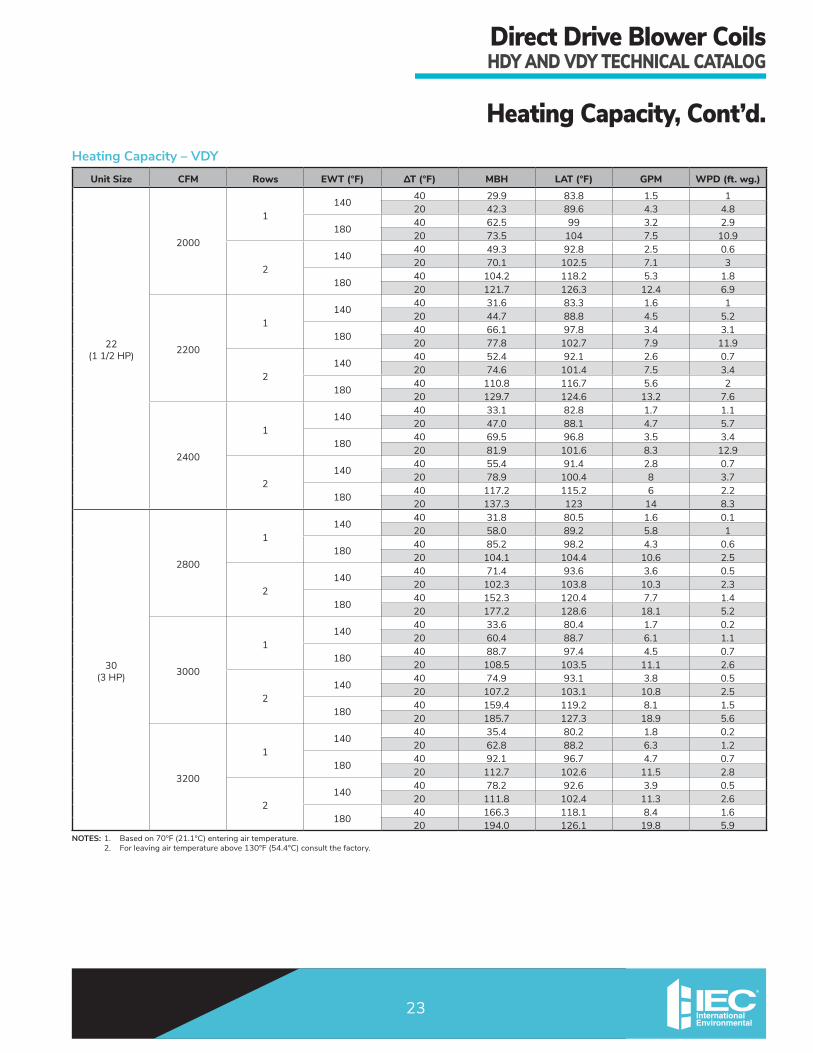
HeatingCapacity,Cont’d.Heating Capacity – VDY
NOTES:1. Basedon70°F(21.1°C)enteringairtemperature. 2. Forleavingairtemperatureabove130°F(54.4°C)consultthefactory.
Unit Size CFM Rows EWT (°F) ΔT (°F) MBH LAT (°F) GPM WPD (ft. wg.)
06(1/2HP)
500
1140
40 8.8 86.3 0.4 0.520 12.8 93.8 1.3 2.5
18040 19.0 105.2 1 1.520 22.4 111.4 2.3 5.6
2140
40 14.6 97.1 0.7 0.420 20.8 108.6 2.1 1.8
18040 31.1 127.6 1.6 1.120 35.8 136.4 3.7 3.9
600
1140
40 9.9 85.3 0.5 0.620 14.4 92.2 1.5 2.9
18040 21.3 102.9 1.1 1.820 25.1 108.8 2.6 6.7
2140
40 16.7 95.7 0.8 0.420 23.7 106.6 2.4 2.2
18040 35.3 124.5 1.8 1.320 40.9 133.1 4.2 4.8
700
1140
40 10.9 84.4 0.5 0.720 15.8 90.9 1.6 3.4
18040 23.4 100.9 1.2 220 27.7 106.6 2.8 7.8
2140
40 18.5 94.5 0.9 0.520 26.3 104.8 2.7 2.6
18040 39.2 121.9 2 1.520 45.5 130.2 4.6 5.7
08(1HP)
700
1140
40 10.0 83.3 0.5 0.620 14.7 89.4 1.5 3
18040 21.7 98.7 1.1 1.820 25.6 103.9 2.6 6.9
2140
40 17.3 92.9 0.9 0.520 24.8 102.8 2.5 2.3
18040 36.8 118.7 1.9 1.420 42.9 126.7 4.4 5.2
800
1140
40 11.1 82.9 0.6 0.720 16.2 88.7 1.6 3.5
18040 23.9 97.7 1.2 2.120 28.3 102.8 2.9 8.1
2140
40 19.3 92.3 1 0.520 27.5 101.8 2.8 2.7
18040 40.9 117.3 2.1 1.720 47.7 125.2 4.9 6.2
900
1140
40 12.1 82.5 0.6 0.820 17.6 88.2 1.8 4
18040 26.1 96.8 1.3 2.420 30.9 101.8 3.2 9.3
2140
40 21.1 91.7 1.1 0.620 30.1 101 3 3.2
180 40 44.8 116.1 2.3 1.920 52.3 123.8 5.3 7.1

DirectDriveBlowerCoilsHDYANDVDYTECHNICALCATALOG
21
HeatingCapacity,Cont’d.Heating Capacity – VDY
NOTES:1. Basedon70°F(21.1°C)enteringairtemperature. 2. Forleavingairtemperatureabove130°F(54.4°C)consultthefactory.
Unit Size CFM Rows EWT (°F) ΔT (°F) MBH LAT (°F) GPM WPD (ft. wg.)
10(1/2HP)
900
1140
40 16.1 86.5 0.8 1.520 22.0 92.6 2.2 7.1
18040 32.6 103.6 1.7 4.320 37.8 108.9 3.9 15.9
2140
40 27.3 98.1 1.4 1.220 36.2 107.2 3.6 5.3
18040 54.1 125.7 2.8 3.220 61.6 133.4 6.3 11.5
1000
1140
40 17.1 85.9 0.9 1.720 23.4 91.7 2.4 7.9
18040 34.8 102.2 1.8 4.820 40.4 107.4 4.1 17.7
2140
40 29.3 97.1 1.5 1.320 38.9 106 3.9 5.9
18040 58.2 123.9 3 3.620 66.3 131.4 6.8 13
1100
1140
40 18.1 85.2 0.9 1.820 24.8 90.9 2.5 8.7
18040 36.8 101 1.9 5.220 42.8 106 4.4 19.4
2140
40 31.2 96.2 1.6 1.420 41.5 105 4.2 6.5
18040 62.1 122.2 3.2 420 70.9 129.7 7.2 14.4
12(1HP)
1100
1140
40 18.1 85.2 0.9 1.820 24.8 90.9 2.5 8.7
18040 36.8 101 1.9 5.220 42.8 106 4.4 19.4
2140
40 31.2 96.2 1.6 1.420 41.5 105 4.2 6.5
18040 62.1 122.2 3.2 420 70.9 129.7 7.2 14.4
1200
1140
40 19.0 84.7 1 220 26.2 90.2 2.6 9.4
18040 38.8 99.9 2 5.720 45.1 104.8 4.6 21
2140
40 33.0 95.4 1.7 1.620 44.0 104 4.4 7.2
18040 65.8 120.7 3.3 4.420 75.2 128 7.7 15.8
1300
1140
40 19.9 84.2 1 2.120 27.4 89.5 2.8 10.1
18040 40.7 99 2.1 6.120 0.0
2140
40 34.7 94.7 1.7 1.720 46.4 103.1 4.7 7.8
180 40 69.3 119.4 3.5 4.720 79.4 126.6 8.1 17.2

DirectDriveBlowerCoilsHDYANDVDYTECHNICALCATALOG
22
HeatingCapacity,Cont’d.Heating Capacity – VDY
NOTES:1. Basedon70°F(21.1°C)enteringairtemperature. 2. Forleavingairtemperatureabove130°F(54.4°C)consultthefactory.
Unit Size CFM Rows EWT (°F) ΔT (°F) MBH LAT (°F) GPM WPD (ft. wg.)
16(1HP)
1400
1140
40 21.2 84 1.1 0.520 31.2 90.7 3.1 2.5
18040 46.2 100.5 2.3 1.520 54.7 106.2 5.6 5.7
2140
40 39.5 96.1 2 0.920 53.4 105.3 5.4 4.1
18040 79.7 122.7 4.1 2.520 91.4 130.4 9.3 9.1
1600
1140
40 23.0 83.3 1.2 0.520 33.8 89.6 3.4 2.8
18040 50.0 98.9 2.5 1.720 59.3 104.3 6 6.5
2140
40 43.1 95 2.2 120 58.4 103.8 5.9 4.8
18040 87.2 120.5 4.4 2.920 100.2 128 10.2 10.6
1800
1140
40 24.7 82.7 1.2 0.620 36.3 88.7 3.7 3.2
18040 53.6 97.5 2.7 1.920 63.7 102.7 6.5 7.3
2140
40 46.5 93.9 2.3 1.120 63.2 102.5 6.4 5.4
18040 94.2 118.4 4.8 3.320 108.5 125.8 11.1 12
20(1HP)
1800
1140
40 28.1 84.4 1.4 0.920 39.7 90.4 4 4.4
18040 58.8 100.2 3 2.620 69.0 105.5 7 9.9
2140
40 45.9 93.6 2.3 0.520 65.4 103.6 6.6 2.7
18040 97.2 120 4.9 1.720 113.3 128.3 11.5 6.2
2000
1140
40 29.9 83.8 1.5 120 42.3 89.6 4.3 4.8
18040 62.5 99 3.2 2.920 73.5 104 7.5 10.9
2140
40 49.3 92.8 2.5 0.620 70.1 102.5 7.1 3
18040 104.2 118.2 5.3 1.820 121.7 126.3 12.4 6.9
2200
1140
40 31.6 83.3 1.6 120 44.7 88.8 4.5 5.2
18040 66.1 97.8 3.4 3.120 77.8 102.7 7.9 11.9
2140
40 52.4 92.1 2.6 0.720 74.6 101.4 7.5 3.4
180 40 110.8 116.7 5.6 220 129.7 124.6 13.2 7.6
DirectDriveBlowerCoilsHDYANDVDYTECHNICALCATALOG
23
HeatingCapacity,Cont’d.Heating Capacity – VDY
NOTES:1. Basedon70°F(21.1°C)enteringairtemperature. 2. Forleavingairtemperatureabove130°F(54.4°C)consultthefactory.
Unit Size CFM Rows EWT (°F) ΔT (°F) MBH LAT (°F) GPM WPD (ft. wg.)
22(11/2HP)
2000
1140
40 29.9 83.8 1.5 120 42.3 89.6 4.3 4.8
18040 62.5 99 3.2 2.920 73.5 104 7.5 10.9
2140
40 49.3 92.8 2.5 0.620 70.1 102.5 7.1 3
18040 104.2 118.2 5.3 1.820 121.7 126.3 12.4 6.9
2200
1140
40 31.6 83.3 1.6 120 44.7 88.8 4.5 5.2
18040 66.1 97.8 3.4 3.120 77.8 102.7 7.9 11.9
2140
40 52.4 92.1 2.6 0.720 74.6 101.4 7.5 3.4
18040 110.8 116.7 5.6 220 129.7 124.6 13.2 7.6
2400
1140
40 33.1 82.8 1.7 1.120 47.0 88.1 4.7 5.7
18040 69.5 96.8 3.5 3.420 81.9 101.6 8.3 12.9
2140
40 55.4 91.4 2.8 0.720 78.9 100.4 8 3.7
18040 117.2 115.2 6 2.220 137.3 123 14 8.3
30(3HP)
2800
1140
40 31.8 80.5 1.6 0.120 58.0 89.2 5.8 1
18040 85.2 98.2 4.3 0.620 104.1 104.4 10.6 2.5
2140
40 71.4 93.6 3.6 0.520 102.3 103.8 10.3 2.3
18040 152.3 120.4 7.7 1.420 177.2 128.6 18.1 5.2
3000
1140
40 33.6 80.4 1.7 0.220 60.4 88.7 6.1 1.1
18040 88.7 97.4 4.5 0.720 108.5 103.5 11.1 2.6
2140
40 74.9 93.1 3.8 0.520 107.2 103.1 10.8 2.5
18040 159.4 119.2 8.1 1.520 185.7 127.3 18.9 5.6
3200
1140
40 35.4 80.2 1.8 0.220 62.8 88.2 6.3 1.2
18040 92.1 96.7 4.7 0.720 112.7 102.6 11.5 2.8
2140
40 78.2 92.6 3.9 0.520 111.8 102.4 11.3 2.6
180 40 166.3 118.1 8.4 1.620 194.0 126.1 19.8 5.9

DirectDriveBlowerCoilsHDYANDVDYTECHNICALCATALOG
24
StaticResistanceTableComponent Static Resistance Table (in w.c.)
Unit Size
Nominal CFM
Dry Coil (includes cabinet)Filters
Mixing Box
1" MERV 8 Pleated
(Qty. 2) 1" Throw-
away
2" MERV 8 Pleated
2" MERV 11 w/Prefilter
4” MERV 11 Pleated
4” MERV 13 Pleated
4Row
5Row
6Row
7Row
8Row
06
400 0.07 0.08 0.10 0.11 0.12 0.07 0.05 0.04 0.04 0.03 0.04 0.02500 0.11 0.13 0.16 0.18 0.19 0.11 0.07 0.05 0.06 0.05 0.06 0.03600 0.15 0.19 0.22 0.24 0.27 0.14 0.09 0.06 0.07 0.06 0.08 0.04700 0.20 0.24 0.28 0.31 0.34 0.17 0.11 0.08 0.09 0.08 0.10 0.06800 0.24 0.29 0.34 0.38 0.42 0.21 0.14 0.09 0.11 0.09 0.12 0.08
08
600 0.15 0.19 0.22 0.24 0.27 0.14 0.09 0.06 0.07 0.06 0.08 0.04700 0.20 0.24 0.28 0.31 0.34 0.17 0.11 0.08 0.09 0.08 0.10 0.06800 0.24 0.29 0.34 0.38 0.42 0.21 0.14 0.09 0.11 0.09 0.12 0.08900 0.28 0.34 0.40 0.45 0.49 0.24 0.16 0.10 0.12 0.10 0.14 0.101000 0.33 0.40 0.46 0.52 0.57 0.27 0.18 0.12 0.14 0.12 0.16 0.12
10
800 0.12 0.14 0.16 0.18 0.21 0.10 0.08 0.06 0.13 0.05 0.05 0.04900 0.15 0.18 0.21 0.24 0.26 0.12 0.09 0.07 0.16 0.06 0.06 0.051000 0.19 0.22 0.26 0.29 0.32 0.14 0.11 0.08 0.18 0.07 0.07 0.061100 0.22 0.26 0.30 0.34 0.37 0.16 0.13 0.09 0.21 0.08 0.08 0.081200 0.25 0.30 0.35 0.39 0.43 0.18 0.14 0.10 0.23 0.09 0.09 0.09
12
1000 0.19 0.22 0.26 0.29 0.32 0.14 0.11 0.08 0.18 0.07 0.07 0.061100 0.22 0.26 0.30 0.34 0.37 0.16 0.13 0.09 0.21 0.08 0.08 0.081200 0.25 0.30 0.35 0.39 0.43 0.18 0.14 0.10 0.23 0.09 0.09 0.091300 0.29 0.34 0.40 0.44 0.48 0.19 0.16 0.11 0.25 0.10 0.10 0.111400 0.32 0.38 0.44 0.49 0.54 0.21 0.18 0.12 0.28 0.11 0.11 0.13
16
1400 0.19 0.23 0.28 0.31 0.34 0.14 0.17 0.10 0.21 0.09 0.09 0.071500 0.22 0.26 0.31 0.35 0.38 0.16 0.19 0.10 0.24 0.10 0.10 0.091600 0.24 0.29 0.35 0.38 0.42 0.17 0.21 0.11 0.26 0.11 0.11 0.101700 0.27 0.32 0.38 0.42 0.47 0.19 0.22 0.12 0.28 0.12 0.12 0.111800 0.29 0.35 0.42 0.46 0.51 0.20 0.24 0.13 0.30 0.12 0.13 0.12
20
1800 0.22 0.27 0.32 0.37 0.42 0.18 0.17 0.11 0.24 0.10 0.13 0.071900 0.24 0.30 0.36 0.41 0.46 0.19 0.18 0.12 0.26 0.11 0.14 0.082000 0.27 0.33 0.39 0.45 0.50 0.21 0.20 0.13 0.28 0.12 0.15 0.092100 0.29 0.36 0.42 0.49 0.55 0.22 0.21 0.13 0.30 0.13 0.16 0.102200 0.31 0.39 0.46 0.53 0.59 0.24 0.23 0.14 0.32 0.14 0.17 0.112300 0.34 0.42 0.49 0.57 0.64 0.25 0.25 0.15 0.34 0.15 0.18 0.122400 0.36 0.44 0.53 0.60 0.68 0.27 0.26 0.16 0.36 0.16 0.20 0.13
22
1800 0.22 0.27 0.32 0.37 0.42 0.18 0.17 0.11 0.24 0.10 0.13 0.071900 0.24 0.30 0.36 0.41 0.46 0.19 0.18 0.12 0.26 0.11 0.14 0.082000 0.27 0.33 0.39 0.45 0.50 0.21 0.20 0.13 0.28 0.12 0.15 0.092100 0.29 0.36 0.42 0.49 0.55 0.22 0.21 0.13 0.30 0.13 0.16 0.102200 0.31 0.39 0.46 0.53 0.59 0.24 0.23 0.14 0.32 0.14 0.17 0.112300 0.34 0.42 0.49 0.57 0.64 0.25 0.25 0.15 0.34 0.15 0.18 0.122400 0.36 0.44 0.53 0.60 0.68 0.27 0.26 0.16 0.36 0.16 0.20 0.13
30
2400 0.17 0.21 0.24 0.28 0.33 0.15 0.14 0.10 0.19 0.07 0.11 0.072600 0.20 0.24 0.28 0.33 0.38 0.16 0.16 0.11 0.22 0.08 0.13 0.092800 0.23 0.27 0.32 0.38 0.43 0.18 0.17 0.12 0.24 0.09 0.14 0.103000 0.26 0.31 0.36 0.42 0.49 0.20 0.19 0.14 0.26 0.10 0.16 0.113200 0.29 0.34 0.40 0.47 0.54 0.22 0.21 0.15 0.28 0.12 0.18 0.133400 0.32 0.38 0.44 0.52 0.59 0.24 0.23 0.16 0.31 0.13 0.19 0.15

DirectDriveBlowerCoilsHDYANDVDYTECHNICALCATALOG
25
SoundPowerDataSound Power Data – HDY
NOTES:1. UnitTestConfiguration:RearReturn/FrontSupply,4Row,10FPICoil,115/1PH/60HzVACMotor,2”FiberglassFilter,1”dualdensityfiberglassinsulation. 2. TestingperAHRI260-2001:4.2.2.3Casingradiatedwithfreeinlet,SoundRatingofDuctedAirMovingandConditioningEquipment. 3. TestingperAHRI260-2001:4.2.2.1Ducteddischarge,SoundRatingofDuctedAirMovingandConditioningEquipment. 4. Size22&30UnitTestConfiguration:RearReturn/FrontSupply,4Row,10FPICoil,460/3PH/60HzVACMotor,2”FiberglassFilter,1”dualdensityfiberglassinsulation. 5. Soundpowerdataisexpressedindecibels,dBRE:1x10-12w(picowatts).
UNIT SIZE RATING FAN
SPEED CFMSOUND POWER LEVEL, Lw (dB reference one picowatt) A-wgt
(dBA)Motor
HP125 Hz 250 Hz 500 Hz 1K Hz 2K Hz 4K Hz 8K Hz
06
CASING RADIATED
NOTE2975
600@
.50”ESP
64 59 55 51 46 40 35 57
1/2DUCTED
DISCHARGE NOTE3
63 53 53 51 50 45 37 57
08
CASING RADIATED
NOTE21,075
800@
.50”ESP
64 60 60 58 56 54 45 64
1DUCTED
DISCHARGE NOTE3
64 61 58 56 50 43 36 60
10
CASING RADIATED
NOTE21,140
1,000@
.50”ESP
70 65 59 59 55 49 41 64
1/2DUCTED
DISCHARGE NOTE3
68 63 65 64 61 60 53 68
12
CASING RADIATED
NOTE21,235
1,200@
.50”ESP
73 69 61 62 57 51 44 67
1DUCTED
DISCHARGE NOTE3
72 67 67 67 64 63 57 72
16
CASING RADIATED
NOTE21,066
1,600@
.50”ESP
73 69 62 64 60 55 48 68
1DUCTED
DISCHARGE NOTE3
72 68 69 70 68 68 63 75
20
CASING RADIATED
NOTE2910
2,000@
.50”ESP
74 69 60 59 56 51 42 66
1DUCTED
DISCHARGE NOTE3
71 67 66 66 64 63 57 71
22 NOTE4
CASING RADIATED
NOTE2950
2,200@
.50”ESP
73 69 60 60 58 53 45 66
1-1/2DUCTED
DISCHARGE NOTE3
73 68 65 67 64 63 57 72
30 NOTE4
CASING RADIATED
NOTE2860
3,000@
.50”ESP
74 70 65 63 61 57 49 69
3DUCTED
DISCHARGE NOTE3
71 73 75 72 70 70 64 78

DirectDriveBlowerCoilsHDYANDVDYTECHNICALCATALOG
26
SoundPowerData,Cont’d.Sound Power Data – VDY
NOTES:1. UnitTestConfiguration:FrontReturn/TopSupply,4Row,10FPICoil,115/1PH/60HzVACMotor,2”FiberglassFilter,1”dualdensityfiberglassinsulation. 2. TestingperAHRI260-2001:4.2.2.3Casingradiatedwithfreeinlet,SoundRatingofDuctedAirMovingandConditioningEquipment. 3. TestingperAHRI260-2001:4.2.2.1Ducteddischarge,SoundRatingofDuctedAirMovingandConditioningEquipment. 4. UnitTestConfiguration:FrontReturn/TopSupply,4Row,10FPICoil,230/1PH/60HzVACMotor,2”FiberglassFilter,1”dualdensityfiberglassinsulation. 5. UnitTestConfiguration:FrontReturn/TopSupply,4Row,10FPICoil,230/3PH/60HzVACMotor,2”FiberglassFilter,1”dualdensityfiberglassinsulation. 6. Soundpowerdataisexpressedindecibels,dBRE:1x10-12w(picowatts).
UNIT SIZE RATING FAN
SPEED CFMSOUND POWER LEVEL, Lw (dB reference one picowatt) A-wgt
(dBA)Motor
HP125 Hz 250 Hz 500 Hz 1K Hz 2K Hz 4K Hz 8K Hz
6
CASING RADIATED
NOTE2960
600@
.50”ESP
68 62 59 56 50 42 38 58
1/2DUCTED
DISCHARGE NOTE3
64 58 52 56 51 45 39 55
8
CASING RADIATED
NOTE21,065
800@
.50”ESP
69 64 62 62 54 47 40 61
1DUCTED
DISCHARGE NOTE3
67 62 59 63 58 54 46 61
10NOTE4
CASING RADIATED
NOTE21,095
1,000@
.50”ESP
70 63 61 62 55 49 42 61
1/2DUCTED
DISCHARGE NOTE3
67 66 63 65 60 55 49 63
12NOTE4
CASING RADIATED
NOTE21,220
1,200@
.50”ESP
70 73 64 66 59 52 45 65
1DUCTED
DISCHARGE NOTE3
69 70 65 68 64 60 54 67
16NOTE5
CASING RADIATED
NOTE21,160
1,600@
.50”ESP
75 68 65 67 61 54 46 65
1DUCTED
DISCHARGE NOTE3
72 69 67 72 67 63 57 69
20NOTE5
CASING RADIATED
NOTE21,020
2,000@
.50”ESP
76 67 67 65 58 51 42 65
1DUCTED
DISCHARGE NOTE3
72 67 69 70 63 61 53 68
22 NOTE5
CASING RADIATED
NOTE21,085
2,200@
.50”ESP
79 73 72 69 62 57 48 69
1-1/2DUCTED
DISCHARGE NOTE3
75 71 74 76 68 66 61 73
30 NOTE5
CASING RADIATED
NOTE2915
3,000@
.50”ESP
77 67 71 67 61 57 48 67
3DUCTED
DISCHARGE NOTE3
71 72 77 74 68 67 59 72

DirectDriveBlowerCoilsHDYANDVDYTECHNICALCATALOG
27
0
0.25
0.5
0.75
1
1.25
1.5
1.75
2
2.25
0 200 400 600 800 1000 1200
TOTA
L ST
ATI
C PR
ESSU
RE
SCFM
HDY06, 1/2 hp Motor
400 600 800 1000 1200 1400RPM
RECOMMENDEDOPERATING RANGE
(10.0 VDC)
(5.2 VDC)
(2.7 VDC)
0
0.25
0.5
0.75
1
1.25
1.5
1.75
2
2.25
2.5
2.75
0 200 400 600 800 1000 1200 1400 1600
TOTA
L ST
ATI
C PR
ESSU
RE
SCFM
HDY08, 1 hp Motor
400 600 800 1000 1200
1400 1600 1800
RECOMMENDED OPERATING RANGE
RPM
(10.0 VDC)(9.7 VDC)
(5.1 VDC)
(3.5 VDC)
(5.2 VDC)
FanCurves–HDYOperatingunitsoutsidetherecommendedoperatingrangecancausetheelectricheaternuisancetripping,condensate carryover and/or fan instability.
Recommendedoperatingrangecontrolvoltagesettingsshownforreferenceonly.Consultfactoryforspecificvoltagesettings per application.
HDY 06, 1/2 HP Motor
HDY 08, 1 HP Motor

DirectDriveBlowerCoilsHDYANDVDYTECHNICALCATALOG
28
0
0.25
0.5
0.75
1
1.25
1.5
1.75
2
2.25
2.5
200 400 600 800 1000 1200 1400 1600 1800 2000
TOTA
L ST
ATI
C PR
ESSU
RE
SCFM
HDY12, 1 hp Motor
600 800 1000 1200
1400 1600 1800
RECOMMENDED OPERATING RANGE
RPM
(10.0 VDC)
(10.0 VDC)
(8.6 VDC)
(6.4 VDC)
(3.5 VDC)
(6.2 VDC)
FanCurves–HDY,Cont’d.
0
0.25
0.5
0.75
1
1.25
1.5
1.75
2
2.25
2.5
200 400 600 800 1000 1200 1400 1600 1800 2000
TOTA
L ST
ATI
C PR
ESSU
RE
SCFM
HDY10, 1/2 hp Motor
600 800 1000 1200
1400 1600 1800
RPM
RECOMMENDED OPERATING RANGE
(6.2 VDC)
(6.4 VDC)(3.7 VDC)
(8.5 VDC)
(10.0 VDC)
HDY 10, 1/2 HP Motor
HDY 12, 1 HP Motor

DirectDriveBlowerCoilsHDYANDVDYTECHNICALCATALOG
29
FanCurves–HDY,Cont’d.
0
0.25
0.5
0.75
1
1.25
1.5
1.75
2
2.25
2.5
2.75
3
400 600 800 1000 1200 1400 1600 1800 2000 2200 2400
TOTA
L ST
ATI
C PR
ESSU
RE
SCFM
HDY16, 1 hp Motor
600 800 1000 1200
1400 1600
RPM
RECOMMENDED OPERATING RANGE
(10.0 VDC)
(9.0 VDC)
(6.5 VDC)
(3.7 VDC)
0
0.25
0.5
0.75
1
1.25
1.5
1.75
2
2.25
2.5
2.75
3
400 800 1200 1600 2000 2400 2800
TOTA
L ST
ATI
C PR
ESSU
RE
SCFM
HDY20, 1 hp Motor
600 800 1000 1200 1400RPM
RECOMMENDED OPERATING RANGE
(10.0 VDC)
(8.5 VDC)
(6.6 VDC)
(4.8 VDC)
HDY 16, 1 HP Motor
HDY 20, 1 HP Motor

DirectDriveBlowerCoilsHDYANDVDYTECHNICALCATALOG
30
FanCurves–HDY,Cont’d.
0
0.25
0.5
0.75
1
1.25
1.5
1.75
2
2.25
2.5
2.75
3
3.25
3.5
0 500 1000 1500 2000 2500 3000 3500 4000 4500
TOTA
L ST
ATI
C PR
ESSU
RE
SCFM
HDY30, 3 hp Motor
600 800 1000 1200 1400RPM
RECOMMENDED OPERATING RANGE
0
0.25
0.5
0.75
1
1.25
1.5
1.75
2
2.25
2.5
2.75
3
400 800 1200 1600 2000 2400 2800
TOTA
L ST
ATI
C PR
ESSU
RE
SCFM
HDY22, 1.5 hp Motor
600 800 1000 1200 1400RPM
RECOMMENDED OPERATING RANGE
(10.0 VDC)
(10.0 VDC)
(4.1 VDC)
(10.0 VDC)
(8.8 VDC)
(5.6 VDC)
(9.0 VDC)
(5.6 VDC)
(3.7 VDC)
(5.9 VDC)
HDY 22, 1-1/2 HP Motor
HDY 30, 3 HP Motor

DirectDriveBlowerCoilsHDYANDVDYTECHNICALCATALOG
31
FanCurves–VDY
0
0.25
0.5
0.75
1
1.25
1.5
1.75
2
2.25
0 200 400 600 800 1000 1200
TOTA
L ST
ATI
C PR
ESSU
RE
SCFM
VDY06, 1/2 HP Motor
400 600 800 1000 1200 1400RPM
RECOMMENDEDOPERATING RANGE
(2.7 VDC)
(5.2 VDC)
(10.0 VDC)
0
0.25
0.5
0.75
1
1.25
1.5
1.75
2
2.25
2.5
2.75
0 200 400 600 800 1000 1200 1400 1600
TOTA
L ST
ATI
C PR
ESSU
RE
SCFM
VDY08, 1 HP Motor
400 600 800 1000 1200
1400 1600 1800
RECOMMENDED OPERATING RANGE
RPM
(3.5 VDC)
(5.1 VDC)
(9.7 VDC)(10.0 VDC)
(5.2 VDC)

DirectDriveBlowerCoilsHDYANDVDYTECHNICALCATALOG
32
FanCurves–VDY,Cont’d.
0
0.25
0.5
0.75
1
1.25
1.5
1.75
2
2.25
2.5
200 400 600 800 1000 1200 1400 1600 1800 2000
TOTA
L ST
ATI
C PR
ESSU
RE
SCFM
VDY10, 1/2 HP Motor
600 800 1000 1200
1400 1600 1800
RPM
RECOMMENDED OPERATING RANGE
(3.7 VDC)
(6.2 VDC)
(10.0 VDC)
(8.5 VDC)
(6.4 VDC)
0
0.25
0.5
0.75
1
1.25
1.5
1.75
2
2.25
2.5
200 400 600 800 1000 1200 1400 1600 1800 2000
TOTA
L ST
ATI
C PR
ESSU
RE
SCFM
VDY12, 1 HP Motor
600 800 1000 1200
1400 1600 1800
RECOMMENDED OPERATING RANGE
RPM
(3.5 VDC)
(6.2 VDC)
(10.0 VDC)(10.0 VDC)
(8.6 VDC)
(6.0 VDC)

DirectDriveBlowerCoilsHDYANDVDYTECHNICALCATALOG
33
FanCurves–VDY,Cont’d.
0
0.25
0.5
0.75
1
1.25
1.5
1.75
2
2.25
2.5
2.75
3
400 600 800 1000 1200 1400 1600 1800 2000 2200 2400
TOTA
L ST
ATI
C PR
ESSU
RE
SCFM
VDY16, 1 HP Motor
600 800 1000 1200
1400 1600
RPM
RECOMMENDED OPERATING RANGE
(3.7 VDC)
(5.3 VDC)
(10.0 VDC)
(9.0 VDC)
(6.5 VDC)
0
0.25
0.5
0.75
1
1.25
1.5
1.75
2
2.25
2.5
2.75
3
400 800 1200 1600 2000 2400 2800
TOTA
L ST
ATI
C PR
ESSU
RE
SCFM
VDY20, 1 HP Motor
600 800 1000 1200 1400RPM
RECOMMENDED OPERATING RANGE
(4.8 VDC)
(10.0 VDC)
(8.5 VDC)
(6.6 VDC)

DirectDriveBlowerCoilsHDYANDVDYTECHNICALCATALOG
34
FanCurves–VDY,Cont’d.
0
0.25
0.5
0.75
1
1.25
1.5
1.75
2
2.25
2.5
2.75
3
400 800 1200 1600 2000 2400 2800
TOTA
L ST
ATI
C PR
ESSU
RE
SCFM
VDY22, 1.5 HP Motor
600 800 1000 1200 1400RPM
RECOMMENDED OPERATING RANGE
(4.1 VDC)
(8.8 VDC)
(10.0 VDC)
(10.0 VDC)
(5.6 VDC)
0
0.25
0.5
0.75
1
1.25
1.5
1.75
2
2.25
2.5
2.75
3
3.25
3.5
0 500 1000 1500 2000 2500 3000 3500 4000 4500
TOTA
L ST
ATI
C PR
ESSU
RE
SCFM
VDY30, 3 HP Motor
600 800 1000 1200 1400RPM
RECOMMENDED OPERATING RANGE
(3.7 VDC)
(5.9 VDC)
(10.0 VDC)
(9.0 VDC)
(5.6 VDC)

DirectDriveBlowerCoilsHDYANDVDYTECHNICALCATALOG
35
SubmittalDataHDY–HorizontalDirectDrive
NOTES:1. RHshown,LHopposite. 2. Alldimensionsare+/-1/4”(6mm). 3. Productspecificationsaresubjecttochangeswithoutnotice. 4. Dimensionsinparenthesisareshowninmillimeters. 5. Allowadequatespacingormaneuverabilityaroundunittoallowservicethroughrecommendedaccessarea. 6. “C”dimensionismeasuredfromcoilsideofunit. 7. MixingBoxoptionwillvaryreturnductdimensions,refertomixingboxsubmittal. 8. Auxiliarycontrolboxrequiredwith3-speedECmotorsand/orcabinetlightingoption,notrequiredwithlow
voltage(0-10V)controls.
Size Fan Size Depth Width Height Supply Duct Flanges Return Duct Flanges Mounting Holes Aux. Ctrl. Box M
A B C D E F G J K L
HDY06 9x6 36 (914)
28 (711)
19-3/4(502)
8-7/8 (225)
10-7/8 (276)
13-3/4 (349)
2-1/4 (57)
24-1/4 (616)
14 (356)
2-3/4 (70)
27-1/4 (686)
35-1/4 (895)
5-3/4 (146)
2 (51)
HDY08 9x6 36 (914)
28 (711)
19-3/4(502)
8-7/8 (225)
10-7/8 (276)
13-3/4 (349)
2-1/4 (57)
24-1/4 (616)
14 (356)
2-3/4 (70)
27-1/4 (686)
35-1/4 (895)
5-3/4 (146)
2 (51)
HDY10 9x6 37-1/2 (953)
37(940)
21-1/2(546)
10-1/4 (260)
10-7/8 (276)
14-1/2 (368)
2-1/4 (57)
33-1/4 (845)
15-3/4 (401)
2-7/8 (73)
36-1/4 (921)
37 (940)
5 (124)
2 (51)
HDY12 9x6 37-1/2 (953)
37(940)
21-1/2(546)
10-1/4 (260)
10-7/8 (276)
14-1/2 (368)
2-1/4 (57)
33-1/4 (845)
15-3/4 (401)
2-7/8 (73)
36-1/4 (921)
37 (940)
5 (124)
2 (51)
HDY16 10x7 37-3/4 (959)
47 (1194)
21-1/2(546)
13 (330)
12 (305)
18-3/8 (467)
2-1/4 (57)
43-7/8 (1115)
15-3/4 (401)
2-7/8 (73)
46-1/4 (1175)
37 (940)
1-1/4 (32)
1-1/2 (38)
HDY2011x10 40-1/4
(1022)48
(1219)24 (610)
16-1/4 (413)
13 (330)
17-1/4 (438)
2-1/4 (57)
44-1/4 (1124)
18 (457)
2-7/8 (73)
47-1/4 (1200)
39-1/2 (1033)
2-3/8 (60)
2 (51)HDY22
HDY30 12x12 40-1/4 (1022)
48 (1219)
32-1/4(819)
16-1/4 (413)
14 (356)
16 (406)
7-1/8(181)
44-1/4 (1124)
26-1/2 (673)
1-1/4 (32)
47-1/4 (1200)
39-1/2 (1033)
3-3/4 (95)
2 (51)
Drawing is provided for reference only. Dimensions may vary with options ordered. Consult IEC website for submittal drawings.

DirectDriveBlowerCoilsHDYANDVDYTECHNICALCATALOG
36
SubmittalData,Cont’d.HDY–withOptionalMixingBox
Drawing is provided for reference only. Dimensions may vary with options ordered. Consult IEC website for submittal drawings.
NOTES:1. RHshown,LHopposite. 2. Alldimensionsare+/-1/4”(6mm). 3. Productspecificationsaresubjecttochangeswithoutnotice. 4. Dimensionsinparenthesisareshowninmillimeters. 5. Allowadequatespacingormaneuverabilityaroundunittoallowservicethroughrecommendedaccessarea. 6. “C”dimensionismeasuredfromcoilsideofunit. 7. MixingBoxoptionwillvaryreturnductdimensions,refertomixingboxsubmittal. 8. MixingBoxoptionsinclude:a)Knockdownbaserailsforfieldassembly;b)Pre-assembledMixingBox. 9. LinkagekitsuppliedwithMixingBoxisprovidedforfieldinstallationofactuator. 10.Add2”(51)ifusingaPrefilter,or4”(102)filter. 11.Auxiliarycontrolboxrequiredwith3-speedECmotorsand/orcabinetlightingoption,notrequiredwithlowvoltage(0-10V)controls.
Size Fan Size Depth Unit
Depth Width Height Supply Duct Return Duct (Note 7) Mix Box Mounting Holes Aux. Box
A B C D E F G H J K L
HDY06 9x6 51-5/8 (1311)
36 (914)
28 (711)
22-3/4(578)
8-7/8 (225)
10-7/8 (276)
13-3/4 (349)
2-1/4 (57)
24 (610)
6 (152)
12-1/2 (318)
11 (279)
27-1/4 (686)
35-1/4 (895)
5-3/4 (146)
HDY08 9x6 51-5/8 (1311)
36 (914)
28 (711)
22-3/4(578)
8-7/8 (225)
10-7/8 (276)
13-3/4 (349)
2-1/4 (57)
24 (610)
6 (152)
12-1/2 (318)
11 (279)
27-1/4 (686)
35-1/4 (895)
5-3/4 (146)
HDY10 9x6 55-1/8 (1400)
37-1/2 (953)
37(940)
24-1/2(622)
10-1/4 (260)
10-7/8 (276)
14-1/2 (368)
2-1/4 (57)
33 (838)
8 (203)
14-1/4 (362)
13 (330)
36-1/4 (921)
37 (940)
5 (124)
HDY12 9x6 55-1/8 (1400)
37-1/2 (953)
37(940)
24-1/2(622)
10-1/4 (260)
10-7/8 (276)
14-1/2 (368)
2-1/4 (57)
33 (838)
8 (203)
14-1/4 (362)
13 (330)
36-1/4 (921)
37 (940)
5 (124)
HDY16 10x7 55-3/8 (1407)
37-3/4 (959)
47 (1194)
24-1/2(622)
13 (330)
12 (305)
18-3/8 (467)
2-1/4 (57)
43 (1092)
8 (203)
14-1/4 (362)
13 (330)
46-1/4 (1175)
37 (940)
1-1/4 (32)
HDY2011x10 57-3/4
(1467)40-1/4 (1022)
48 (1219)
27(686)
16-1/4 (413)
13 (330)
17-1/4 (438)
2-1/4 (57)
44 (1118)
8 (203)
16-3/4 (425)
13 (330)
47-1/4 (1200)
39-1/2 (1033)
2-3/8 (60)HDY22
HDY30 12x12 59-3/4 (1518)
40-1/4 (1022)
48 (1219)
35-1/4(895)
16-1/4 (413)
14 (356)
16 (406)
7-1/8(181)
44 (1118)
10 (254)
15 (381)
15 (381)
47-1/4 (1200)
39-1/2 (1033)
3-3/4 (95)

DirectDriveBlowerCoilsHDYANDVDYTECHNICALCATALOG
37
SubmittalData,Cont’d.VDY–VerticalDirectDrive
NOTES:1. RHshown,LHopposite. 2. Alldimensionsare+/-1/4”(6mm). 3. Productspecificationsaresubjecttochangeswithoutnotice. 4. Dimensionsinparenthesisareshowninmillimeters. 5. Allowadequatespacingormaneuverabilityaroundunittoallowservicethroughrecommendedaccessarea. 6. “C”dimensionismeasuredfromcoilsideofunit. 7. MixingBoxoptionwillvaryreturnductdimensions,refertomixingboxsubmittal.
Drawing is provided for reference only. Dimensions may vary with options ordered. Consult IEC website for submittal drawings.
Size Fan Size Depth Width Height Supply Duct Return Duct Aux. Ctrl. Box Unit side to duct flange
Unit bottom to duct flange
A B C E F L M N
06 9x6 20 (508)
28 (711)
36-1/2(927)
8-7/8 (225)
10-7/8 (276)
15-1/8 (384)
24-1/4 (616)
14 (356)
4-1/2 (114)
1-7/8 (48)
2-7/8 (73)
08 9x6 20 (508)
28 (711)
36-1/2(927)
8-7/8 (225)
10-7/8 (276)
15-1/8 (384)
24-1/4 (616)
14 (356)
4-1/2 (114
1-7/8 (48)
2-7/8 (73)
10 9x6 22(559)
37(940)
39-3/8(1000)
10-1/4 (260)
10-7/8 (276)
21-1/2 (546)
33-1/4 (845)
15-3/4 (401)
0 (0)
1-7/8 (48)
2-7/8 (73)
12 9x6 22 (559)
37(940)
39-3/8(1000)
10-1/4 (260)
10-7/8 (276)
21-1/2 (546)
33-1/4 (845)
15-3/4 (401)
0 (0)
1-7/8 (48)
2-7/8 (73)
16 10x7 22 (559)
47 (1194)
39-3/8(1000)
13 (330)
12 (305)
16-5/8 (422)
43-7/8 (1115)
15-3/4 (401) 3(76) 1-5/8
(48)2-7/8 (73)
20/22 11x10 24 (610)
48 (1219)
45-1/8(1146)
16-1/4 (413)
13 (330)
17-1/8 (435)
44-1/4 (1124)
18 (457)
2-1/2 (64)
1-7/8 (48)
3-1/8 (79)
30 12x12 28 (711)
48 (1219)
54-1/4(1378)
16-1/4 (413)
14 (356)
16 (406)
44-1/4 (1124)
26-1/2 (673)
3-5/8 (92)
1-7/8 (48)
2-3/4 (70)

DirectDriveBlowerCoilsHDYANDVDYTECHNICALCATALOG
38
SubmittalData,Cont’d.VDY–withOptionalMixingBox
Drawing is provided for reference only. Dimensions may vary with options ordered. Consult IEC website for submittal drawings.
NOTES:1. RHshown,LHopposite. 2. Alldimensionsare+/-1/4”(6mm). 3. Productspecificationsaresubjecttochangeswithoutnotice. 4. Dimensionsinparenthesisareshowninmillimeters. 5. Allowadequatespacingormaneuverabilityaroundunittoallowservicethroughrecommendedaccessarea. 6. “C”dimensionismeasuredfromcoilsideofunit. 7. MixingBoxoptionwillvaryreturnductdimensions,refertomixingboxsubmittal. 8. MixingBoxoptionsinclude:a)Knockdownbaserailsforfieldassembly;b)Pre-assembledMixingBox. 9. LinkagekitsuppliedwithMixingBoxisprovidedforfieldinstallationofactuator,consistingof2crankarms, 2swivels,andeithera25”(sizes06-16)or34”(sizes20-30)lengthof5/16”rod.. 10.Add2”(51)ifusingaPrefilter,or4”(102)filter..
Size Fan Size Depth Unit Depth Width Height Supply Duct Return Duct Mix Box Aux. Box
Unit side to duct flange
Unit bottom to duct flange
A B C E F H L M N
06 9x6 35-1/2 (902)
20 (508)
28 (711)
36-1/2(927)
8-7/8 (225)
10-7/8 (276)
15-1/8 (384)
24 (610)
6 (152)
11 (279)
4-1/2 (114)
1-7/8 (48)
2-7/8 (73)
08 9x6 35-1/2 (902)
20 (508)
28 (711)
36-1/2(927)
8-7/8 (225)
10-7/8 (276)
15-1/8 (384)
24 (610)
6 (152)
11 (279)
4-1/2 (114)
1(25)
2-7/8 (73)
10 9x6 39-1/2 (1003)
22 (559)
37 (940)
39-3/8(1000)
10-1/4 (260)
10-7/8 (276)
21-1/2 (546)
33 (838)
8 (203)
13 (330)
0 (0)
1-7/8 (48)
2-7/8 (73)
12 9x6 39-1/2 (1003)
22 (559)
37 (940)
39-3/8(1000)
10-1/4 (260)
10-7/8 (276)
21-1/2 (546)
33 (838)
8 (203)
13 (330)
0 (0)
1-7/8 (48)
2-7/8 (73)
16 10x7 39-1/2 (1003)
22 (559)
47 (1194)
39-3/8(1000)
13 (330)
12 (305)
16-5/8 (422)
43 (1092)
8 (203)
13 (330)
3 (76)
1-5/8 (41)
2-7/8 (73)
20/22 11x10 41-1/2 (1054)
24 (610)
48 (1219)
45-1/8(1146)
16-1/4 (413)
13 (330)
17-1/8 (435)
44 (1118)
8 (203)
13 (330)
2-1/2 (64)
1-7/8 (48)
3-1/8 (79)
30 12x12 47-1/2 (1207)
28 (711)
48 (1219)
54-1/4(1378)
16-1/4 (413)
14 (356)
16 (406)
44 (1118)
10 (254)
15 (381)
3-5/8 (92)
1-7/8 (48)
2-7/8 (73)

DirectDriveBlowerCoilsHDYANDVDYTECHNICALCATALOG
39
PipingConnections–HDYPipingConnectionLocation(CenterlinetoCenterline)–HydronicCooling&HeatingCoils
0
0
2(51)
B
C6-
7/8(
175)
8-5/
8(21
9) E
D
1-5/8(41)
A
2-11
/16(
68) G F
10-3
/8(2
64)
Coil Header Connection SizeUnit Size
8 Row 6 Row 4 Row 2 Row HW 1 Row HWNom. Size OD Nom.
Size OD Nom. Size OD Nom.
Size OD Nom. Size OD
06-12 1 1.125 3/4 0.875 3/4 0.875 1/2 0.625 1/2 0.625
16-22 1 1.125 1 1.125 1 1.125 1 1.125 1/2 0.625
30 1-1/2 1.625 1-1/2 1.625 1-1/2 1.625 1-1/2 1.625 1-1/2 1.625
HORIZONTAL,lefthandunitwithre-heatcoilshown.
CR-ColdWaterReturnHR - Hot Water ReturnCS-ColdWaterSupplyHS-HotWaterSupplyRH - Right HandLH - Left Hand
Unit Size Coil Rows A B C D E F GCool Heat
06/08
4– –
6-1/8 12-3/4
– – –5-15/161 3-1/2 15-1/2 7 7
2 3-13/16 15-13/16 7-9/16 7-9/16
6– – – – –
8-1/81 3-1/2 15-1/2 9-3/16 9-3/162 3-13/16 15-13/16 9-3/4 9-3/4
8 – – – – – 10-1/4
10/12
4– –
7-3/4 14-3/8
– – –5-15/161 5-1/8 17-1/8 7 7
2 5-7/16 17-7/16 7-9/16 7-9/16
6– – – – –
8-1/81 5-1/8 17-1/8 9-3/16 9-3/162 5-27/61 17-7/16 9-3/4 9-3/4
8 – – – – – 10-1/4
16
4
– – 7-3/415-5/8
– – –
5-15/161LH10-5/8
7-3/4 129-5/8 7
RH13-3/8 9-5/8 72 12 7 16-3/8 13-5/8 10-3/8 7-9/16
6
– – 7-3/415-5/8
– – –
8-1/81LH10-5/8
7-3/4 1211-13/16 9-3/16
RH13-3/8 11-13/16 9-3/162 12 7 16-3/8 13-5/8 12-1/2 9-3/4
8 – – 9-1/2 15-5/8 – – – 10-1/4
20/22
4
– – 7-13/16
18-3/16
– – –5-15/16
1LH11-15/16
7-13/16 13-5/16 9-5/87RH14-11/16
2 11-9/16 7-7/8 15-13/16 9-1/16 5
6
– – 7-13/16 – – –8-1/8
1LH11-15/16
7-13/16 13-5/16 11-13/169-3/16RH14-11/16
2 11-9/16 7-7/8 15-13/16 11-1/4 7-1/88 – – 7-13/16 – – – 10-1/4
30
4– –
5-15/16 26-5/16
– – – 5-15/161 7-1/16 25-13/16 9
7 4-7/82 10-5/16 23-13/16 9-1/8
6– – – – – 8-1/81 7-1/16 25-13/16 11-1/8
9-1/8 7-1/162 10-5/16 23-13/16 11-5/16
8 – – – – – 10-1/4

DirectDriveBlowerCoilsHDYANDVDYTECHNICALCATALOG
40
PipingConnections–HDY,Cont’d.PipingConnectionLocation(CenterlinetoCenterline)–R-410ACoolingw/HotWaterHeating
HORIZONTAL,lefthandunitwithpre-heatcoilshown.
HR - Hot Water ReturnHS-HotWaterSupplyLL - Liquid LineSL-SuctionLine
Coil Header Connection Size (Nominal OD in Inches)Unit Size
LL SL 2 Row HW 1 Row HWNom. Size OD Nom.
Size OD Nom. Size OD Nom.
Size OD
06-12 1/4 0.375 3/4 0.875 1/2 0.625 1/2 0.625
16-22 1/4 0.375 1 1.125 1 1.125 1/2 0.625
30 1/2 0.625 1-1/2 1.625 1-1/2 1.625 1-1/2 1.625
0
0
2(51)
B
D
6-7/
8(17
5)
8-5/
8(21
9)
A
GH E
1-5/8(41)
F
C
SIZECOIL ROWS
A B C D E F G HDX ONLY WATER
PRE-HEAT
06/08
4 –
4-3/4 5-1/2
– –
12-1/2
2-3/4 – – 6 4
16 18
3-3/4 2-5/8 2-5/86 4
2 4-7/8 3-1/4 3-1/46
10/12
4 –
6-1/2 7-1/8
– –
12-1/2
2-3/4 – – 6 4
15-1/8 17-1/8
3-3/4 2-5/8 2-5/86 4
2 4-7/8 3-1/4 3-1/46
16
4 –
6-1/27-1/8
– –
12-1/2
2-3/4 – – 6 4
1 5-1/8 17-1/8 3-3/4 2-5/8 2-5/86 4
2 6-3/8 10 13-5/8 6-6/8 4-1/8 2-5/86
20/22
4 –
6-1/2 7-1/8 – –
12-1/2
2-3/4 – – 6 4
1 5-1/4 19-3/4 3-3/4 2-5/8 2-5/86 4
2 6-3/4 7-1/4 11-5/8 15-7/8 6-3/4 4-1/4 2-5/86
30
4 – 4-5/8 5-3/8 – –
12-1/2
2-3/4 – – 6 4
14-7/8
6 12-1/8 25-7/8 6-1/84-1/2 2-5/8
6 4
2 5-3/8 10-3/8 23-7/8 6-3/86

DirectDriveBlowerCoilsHDYANDVDYTECHNICALCATALOG
41
PipingConnections–VDYPipingConnectionLocation(CenterlinetoCenterline)–HydronicCooling&HeatingCoils
Coil Header Connection SizeUnit Size
8 Row 6 Row 4 Row 2 Row HW 1 Row HWNom. Size OD Nom.
Size OD Nom. Size OD Nom.
Size OD Nom. Size OD
06-12 1 1.125 3/4 0.875 3/4 0.875 1/2 0.625 1/2 0.625
16-22 1 1.125 1 1.125 1 1.125 1 1.125 1/2 0.625
30 1-1/2 1.625 1-1/2 1.625 1-1/2 1.625 1-1/2 1.625 1-1/2 1.625
VERTICAL,righthandunitwithre-heatcoilshown.
CR-ColdWaterReturnHR - Hot Water ReturnCS-ColdWaterSupplyHS-HotWaterSupplyRH - Right HandLH - Left Hand
Unit Size Coil Rows A B C D E F GCool Heat
06/08
4– –
6-1/8 12-3/4
– – –5-15/161 3-1/2 15-1/2 7 7
2 3-13/16 15-13/16 7-9/16 7-9/16
6– – – – –
8-1/81 3-1/2 15-1/2 9-3/16 9-3/162 3-13/16 15-13/16 9-3/4 9-3/4
8 – – – – – 10-1/4
10/12
4– –
7-3/4 14-3/8
– – –5-15/161 5-1/8 17-1/8 7 7
2 5-7/16 17-7/16 7-9/16 7-9/16
6– – – – –
8-1/81 5-1/8 17-1/8 9-3/16 9-3/162 5-27/61 17-7/16 9-3/4 9-3/4
8 – – – – – 10-1/4
16
4
– – 7-3/415-5/8
– – –
5-15/161LH10-5/8
7-3/4 129-5/8 7
RH13-3/8 9-5/8 72 12 7 16-3/8 13-5/8 10-3/8 7-9/16
6
– – 7-3/415-5/8
– – –
8-1/81LH10-5/8
7-3/4 1211-13/16 9-3/16
RH13-3/8 11-13/16 9-3/162 12 7 16-3/8 13-5/8 12-1/2 9-3/4
8 – – 9-1/2 15-5/8 – – – 10-1/4
20/22
4
– – 7-13/16
18-3/16
– – –5-15/16
1LH11-15/16
7-13/16 13-5/16 9-5/87RH14-11/16
2 11-9/16 7-7/8 15-13/16 9-1/16 5
6
– – 7-13/16 – – –8-1/8
1LH11-15/16
7-13/16 13-5/16 11-13/169-3/16RH14-11/16
2 11-9/16 7-7/8 15-13/16 11-1/4 7-1/88 – – 7-13/16 – – – 10-1/4
30
4– –
5-15/16 26-5/16
– – – 5-15/161 7-1/16 25-13/16 9
7 4-7/82 10-5/16 23-13/16 9-1/8
6– – – – – 8-1/81 7-1/16 25-13/16 11-1/8
9-1/8 7-1/162 10-5/16 23-13/16 11-5/16
8 – – – – – 10-1/4
0
0
2(51)
B
C6-
7/8(1
75)
8-5/8
(219
)
DRAIN
RH UNIT
E
D
1-5/8(41)
A
2-11
/16(6
8) G F10
-3/8(
264)
LH UNITTELL-TALETELL-TALE

DirectDriveBlowerCoilsHDYANDVDYTECHNICALCATALOG
42
PipingConnections–VDY,Cont’d.PipingConnectionLocation(CenterlinetoCenterline)–R-410ACoolingw/HotWaterHeating
VERTICAL,righthandunitwithpre-heatcoilshown.
HR - Hot Water ReturnHS-HotWaterSupplyLL - Liquid LineSL-SuctionLine
Coil Header Connection Size (Nominal OD in Inches)Unit Size
LL SL 2 Row HW 1 Row HWNom. Size OD Nom.
Size OD Nom. Size OD Nom.
Size OD
06-12 1/4 0.375 3/4 0.875 1/2 0.625 1/2 0.625
16-22 1/4 0.375 1 1.125 1 1.125 1/2 0.625
30 1/2 0.625 1-1/2 1.625 1-1/2 1.625 1-1/2 1.625
SIZECOIL ROWS
A B C D E F G HDX ONLY WATER
PRE-HEAT
06/08
4 –
4-3/4 5-1/2
– –
12-1/2
2-3/4 – – 6 4
16 18
3-3/4 2-5/8 2-5/86 4
2 4-7/8 3-1/4 3-1/46
10/12
4 –
6-1/2 7-1/8
– –
12-1/2
2-3/4 – – 6 4
15-1/8 17-1/8
3-3/4 2-5/8 2-5/86 4
2 4-7/8 3-1/4 3-1/46
16
4 –
6-1/27-1/8
– –
12-1/2
2-3/4 – – 6 4
1 5-1/8 17-1/8 3-3/4 2-5/8 2-5/86 4
2 6-3/8 10 13-5/8 6-6/8 4-1/8 2-5/86
20/22
4 –
6-1/2 7-1/8 – –
12-1/2
2-3/4 – – 6 4
1 5-1/4 19-3/4 3-3/4 2-5/8 2-5/86 4
2 6-3/4 7-1/4 11-5/8 15-7/8 6-3/4 4-1/4 2-5/86
30
4 – 4-5/8 5-3/8 – –
12-1/2
2-3/4 – – 6 4
14-7/8
6 12-1/8 25-7/8 6-1/84-1/2 2-5/8
6 4
2 5-3/8 10-3/8 23-7/8 6-3/86
0
0
2(51)
B
6-7/8
(175
)
8-5/8
(219
)
A
G
DRAIN
RH UNIT
E
1-5/8(41)
F
C
LH UNIT
D
H
TELL-TALE TELL-TALE

DirectDriveBlowerCoilsHDYANDVDYTECHNICALCATALOG
43
ElectricHeat
X Available option– Not available option
NOTES:1. ElectricHeatingCapacities(Btuh)=HeaterkWx3413 2. ElectricHeaterAmperageforSingle-phasePower=(HeaterkWx1000)/AppliedVoltage
Single Phase Electric Heater Availability
ElectricheatersareavailableonIECDirectDriveblowercoils for total electric heat.
Total Electric HeatTotal electric heat eliminates the requirement for a boiler and provides heating and/or cooling on an individual basis throughout the year. Electric heat is available only forsinglesourcepower(motorandheatervoltagethesame).
kW
El. Heat Amps Unit SizeHeater Stages
Single Phase (1 or 2 stage) 6 8 10 12 16 20
120V 208V 240V 277V 1stg 2stg 1stg 2stg 1stg 2stg 1stg 2stg 1stg 2stg 1stg 2stg
1.0 8.3 4.8 4.2 3.6 X − X − − − − − − − − −
1.5 12.5 7.2 6.3 5.4 X − X − X − X − − − − −
2.0 16.7 9.6 8.3 7.2 X − X − X − X − − − − −
2.5 20.8 12.0 10.4 9.0 X − X − X − X − X − − −
3.0 25.0 14.4 12.5 10.8 X X X X X X X X X X − −
3.5 29.2 16.8 14.6 12.6 X X X X X X X X X X X X
4.0 33.3 19.2 16.7 14.4 X X X X X X X X X X X X
4.5 37.5 21.6 18.8 16.2 X X X X X X X X X X X X
5.0 − 24.0 20.8 18.1 X X X X X X X X X X X X
6.0 − 28.8 25.0 21.7 X X X X X X X X X X X X
7.0 − 33.7 29.2 25.3 − − X X X X X X X X X X
8.0 − 38.5 33.3 28.9 − − X X X X X X X X X X
9.9 − − − 35.7 − − − − X X X X X X X X
12.0 − − − 43.3 − − − − − − X X X X X X
Heater ConstructionTheheatercoilsofhigh-graderesistancewirearesupportedbyceramicinsulatorsonplatedsteelbrackets.These heat elements are suspended directly in front of theoutletaftertheblowerandthecoil.Anautoandamanualthermallimitswitchprotecttheheaterintheeventofairflowfailure.Forelectricheatcontroloptionsrefertopage46.

DirectDriveBlowerCoilsHDYANDVDYTECHNICALCATALOG
44
ElectricHeat
X Available option– Not available option
NOTES:1. ElectricHeatingCapacities(Btuh)=HeaterkWx3413 2. ElectricHeaterAmperageforSingle-phasePower=(HeaterkWx1000)/AppliedVoltage
Three Phase Electric Heater Availability
kW
Electric Heat Amps Unit SizeHeater Stages
Three Phase(1, 2 or 3 stage) 6 8 10 12 16 20/22 30
208V 240V 480V 1stg 2stg 1stg 2stg 1stg 2stg 1stg 2stg 3stg 1stg 2stg 3stg 1stg 2stg 3stg 1stg 2stg 3stg
1.0 2.8 2.4 1.2 X − X − − − − − − − − − − − − − − −
1.5 4.2 3.6 1.8 X − X − X − X − − − − − − − − − − −
2.0 5.6 4.8 2.4 X − X − X − X − − − − − − − − − − −
2.5 6.9 6.0 3.0 X − X − X − X − − X − − − − − − − −
3.0 8.3 7.2 3.6 X − X − X − X − − X − − − − − − − −
3.5 9.7 8.4 4.2 X − X − X − X − − X − X − − − −
4.0 11.1 9.6 4.8 X X X X X X X X − X X − X X − − − −
4.5 12.5 10.8 5.4 X X X X X X X X − X X − X X − − − −
5.0 13.9 12.0 6.0 X X X X X X X X − X X − X X − − − −
6.0 16.7 14.4 7.2 X X X X X X X X − X X − X X − X X −
7.0 19.4 16.8 8.4 − − X X X X X X − X X − X X − X X −
8.0 22.2 19.2 9.6 − − X X X X X X − X X − X X − X X −
9.9 27.5 23.8 11.9 − − − − X X X X − X X − X X − X X −
12.0 33.3 28.9 14.4 − − − − − − X X X X X X X X X X X X
14.0 38.9 33.7 16.8 − − − − − − − − − X X X X X X X X X
15.0 41.6 36.1 18.0 − − − − − − − − − X X X X X X X X X
16.0 − 38.5 19.2 − − − − − − − − − X X X X X X X X X
18.0 − − 21.7 − − − − − − − − − − − − X X X X X X
19.9 − − 23.9 − − − − − − − − − − − − X X X X X X
25.0 − − 30.1 − − − − − − − − − − − − − − − X X X
30.0 − − 36.1 − − − − − − − − − − − − − − − X X X

DirectDriveBlowerCoilsHDYANDVDYTECHNICALCATALOG
45
MotorDataThermal Overload ProtectionAllstandardmotorsonDirectDriveunitsfurnishedbyIECcontaininternalthermaloverloadprotection.Theoverloadautomaticallyresetswhenthetemperaturereturnstoasafelimit.Thesethermaloverloadsreplacetheneed for motor starters.
MOTOR TYPE VOLTAGE
UNIT SIZE
06, 10 08, 12, 16, 20 22 30
MOTOR HORSEPOWER AND FLA
1/2 HP 1 HP 1-1/2 HP 3 HP
1-PHASESINGLESPEED
STANDARDEFFICIENCY
115V/1PHASE/50-60HZ 6.4 10.7 N/A N/A
208V/1PHASE/50-60HZ 3.8 6.3 N/A N/A
230V/1PHASE/50-60HZ 3.6 5.8 N/A N/A
277V/1PHASE/50-60HZ 3.2 5.1 N/A N/A
3-PHASESINGLESPEED
STANDARDEFFICIENCY
208V/3PHASE/50-60HZ 2.0 3.7 4.4 8.9
230V/3PHASE/50-60HZ 1.85 3.3 4.4 8.9
460V/3PHASE/50-60HZ 1.0 1.75 2.2 4.4

DirectDriveBlowerCoilsHDYANDVDYTECHNICALCATALOG
46
Controls:Motor Controls – Units without electric heat:Twocontrolsschemesareavailable:• 3-Speedadjustable.• Proportional(0-10VDC).
Electric Heat ControlsElectricheaterscomestandardwithatransformer,heatercontactors,motorandelectricheatfusing,andaterminalstrip.
Anoptionalinterlockingdisconnectswitchisavailable.
Condensate Float SwitchAwater-levelsensingdevicedesignedtopreventdrainpanoverflow.Thestandardswitchiswirednormallyclosed.Switchesareavailableonlyin24V.
Cabinet/Control Box Maintenance LightOptionalLEDServiceLightprovidesasourceofillumination in the main unit cabinet and the control box during routine maintenance and troubleshooting in the darkceilingspaces.
MotorControl Board
Equipment GroundTerminalTerminal StripWiring Diagram
(inside the door)
Serial PlateWrapper
ContactorsTransformer
Electric HeaterLimit Switch Knob
Heater Fuses
Auxillary Control Box (supplied when ordered with 3-speed controls and/or service light)
Service Light Strip
Battery Charger
Service Light Battery
Door Switch
Bonded Ground
24V Control Fuse
Disconnect SwitchControl Box
Above picture is the example of Control box with electric heat, disconnect switch and service light.
FactoryInstalledOptions

DirectDriveBlowerCoilsHDYANDVDYTECHNICALCATALOG
47
FactoryInstalledOptions,Cont’d.
NOTES:1. Fanswitchonly;nothermostat
Control Package Applications
Venture 24V,Wi-Fi Programmable
Basic 24V Digital7-Day Programmable andNon-Programmable Series
Unit Type Control Option System Type Changeover Type W P N
- ManualFan Manual1 None - - -
2-Pipe
ValveCycle*
HeatOnly None • • •CoolOnly None • • •
Heat/CoolManual - - -
Automatic • • •
Heat/CoolwithAuxiliaryElectric Heat
Manual - - -
Automatic • • •
CoolwithTotalElectricHeat
Manual - - -
Automatic • • •
4-Pipe Heat/CoolManual - - -
Automatic • • •

DirectDriveBlowerCoilsHDYANDVDYTECHNICALCATALOG
48
FactoryInstalledOptions,Cont’d.
*LEGEND: P • Basic24VDigital,7-DayProgrammable N • Basic24VDigital,Non-Programmable W• Venture24VWi-FiProgrammable
Thermostat Features
NOTES:1. Controlpackageswithvalvecyclecontrolarecontinuousfanoperationonly. 2. Allwall-mountcontrolpackagesareshippedlooseforfieldinstallation.(Boxes,
tilerings,plasterrings,etc.arenotprovided). 3. Aquastatsareincludedincontrolpackages,asrequired.
All listed controls include fan switching.Control Type1
W P N
24V,115V,208V,240V,277V 24V only 24V only 24V only
Wi-FiEnabled • - -
MobileandWebAppforRemoteControl • - -
StagedCooling • - -
Programmable • • -
RemoteWallMounted • • •ManualFanSwitchOperation • • •AutoFanSpeedControl • • •Continuous3-SpeedFan • • •
CyclingFan • • •O.ADamperSignal • • •
RemoteTemperatureSensor Opt Opt Opt
Digital Display & Buttons • • •LocalTemperatureSet-Back • • •
WaterTemperaturePurgeCycle • • •ProportionalControlValves - - -
FloatingControlValves - - -
PipeSensor • • •

DirectDriveBlowerCoilsHDYANDVDYTECHNICALCATALOG
49
UnitWeightCalculationsDistributed Weight Calculations – HDYThefollowingoperatingweightinformationisbasedon8-rowwater-filledcoilsanddoublewallcabinetconstruction.Foradifferentcoilandcabinetoptions,usetheweightcorrectionfactortable.
Horizontal Units (Top View)
HDY UnitNo Electric Heat (lb.) With Electric Heat (lb.)
A B C D Total A B C D Total06 42 46 36 47 171 42 58 36 66 20208 41 47 38 45 171 41 58 36 67 20210 51 53 49 63 217 51 60 56 83 25012 50 52 51 64 217 50 58 57 85 25016 65 70 64 75 274 70 69 66 104 30920 78 90 77 95 340 81 96 77 107 37822 83 105 80 99 367 86 111 81 111 38930 103 113 97 117 430 104 120 96 149 469
Total Weight Unit Correction Factor (lb.) – HDYTheweightsinthetableabovearefor8-rowwater-filledcoilswithdoublewallconstruction.Foradifferentnumberofrows,totalunitweightcanbedeterminedbyfollowingstepsbelow:a. Identifythesizeofunitandnumberofrowsb. Fromtheprevioustable,identifythetotalweightoftheunitc. Fromthetablebelow,identifythecorrectionfactoranddeductthisfactorfromthetotalweight.
Options 6 8 10 12 16 20 22 30
4-RowCoil -21 -21 -28 -28 -39 -46 -46 -98
5-RowCoil -16 -16 -21 -21 -29 -35 -35 -74
6-RowCoil -11 -11 -14 -14 -20 -23 -23 -49
7-RowCoil -5 -5 -7 -7 -10 -12 -12 -25
SingleWallConstruction -31 -31 -40 -40 -47 -58 -58 -67NOTES:1. Unitweights(showninpounds),+/-10percent,arebasedonthelargestwater-filledcoil.

DirectDriveBlowerCoilsHDYANDVDYTECHNICALCATALOG
50
UnitWeightCalculations,Cont’d.Unit Total Weight – VDYThefollowingoperatingweightinformationisbasedon8-rowwater-filledcoilsanddoublewallcabinetconstruction.Foradifferentcoilandcabinetoptions,usetheweightcorrectionfactortable.
Vertical Units (Top View)
Total Unit Weight Adjustment (lb.) – VDYTheseweightsarefor8-rowwater-filledcoilswithdoublewallconstruction.Foradifferentnumberofrows,totalunitweightcanbedeterminedbyfollowingstepsbelow:a. Identifythesizeofunitandnumberofrowsb. Fromtheprevioustable,identifythetotalweightoftheunitc. Fromthetablebelow,identifythecorrectionfactoranddeductthisfactorfromthetotalweight.
NOTES:1. Unitweights(showninpounds),+/-10percent,arebasedonthelargestwater-filledcoil.
CD
AB B
DC
A
LH COIL RH COIL
Vertical Unit Corner Weight
NOTE: Someunitcomponentsareremovedforclarity.
VDY UnitNo Electric Heat (lb.) With Electric Heat (lb.)
A B C D Total A B C D Total06 76 38 35 42 191 85 40 44 49 21808 85 39 37 38 199 94 48 44 47 23410 78 45 44 78 245 86 58 55 84 28312 84 45 46 80 255 97 62 58 92 30916 85 74 62 82 306 105 79 70 92 34620 90 84 77 88 339 111 88 81 99 37922 110 90 73 90 363 133 88 92 99 41230 147 140 113 128 528 160 140 131 137 568
Options 6 8 10 12 16 20 22 30
4-RowCoil -21 -21 -28 -28 -39 -46 -46 -98
5-RowCoil -16 -16 -21 -21 -29 -35 -35 -74
6-RowCoil -11 -11 -14 -14 -20 -23 -23 -49
7-RowCoil -5 -5 -7 -7 -10 -12 -12 -25
SingleWallConstruction -31 -31 -40 -40 -47 -58 -58 -67

DirectDriveBlowerCoilsHDYANDVDYTECHNICALCATALOG
51
FiltersFilters – HDYThestandardDirectDriveBlowerCoilsarefurnishedwithasetof2”pleatedMERV8filters.
Universal Filter Rack Design - Features & Benefits• Sideandbottomfilterremoval• Notoolsneededforeasyfilterchange,usageofstrongmagnetsinplaceofhardware
• Choiceof1”,2”or4”filters• Easytomodifyinthefieldforeither1”,2”or4”filters
• Robustdesigneliminatesunit’ssagging
Unit Size Filter Quantity
Nominal Filter Sizes – Inches (Millimeters)
HDY
06 1 16-1/2"x24"(419x610)
08 1 16-1/2"x24"(419x610)
10 1 18-1/4"x33"(464x838)
12 1 18-1/4"x33"(464x838)
16 2 18-1/4"x21-1/2"(464x546)
20/22 2 20-1/2x22"(521x559)
30 2 29"x22"(737x559)
4” FILTER
2” FILTER
1” FILTER
MAGNETS
DETAIL X
SEE DETAIL X

DirectDriveBlowerCoilsHDYANDVDYTECHNICALCATALOG
52
Filters,Cont’d.Filters – VDYThestandardDirectDriveBlowerCoilsarefurnishedwithasetof2”pleatedMERV8filters.
Universal Filter Rack Design - Features & Benefits• Sideandtopfilterremoval• Notoolsneededforeasyfilterchange,usageofstrongmagnetsinplaceofhardware
• Choiceof1”,2”or4”filters• Easytomodifyinthefieldforeither1”,2”or4”filters
• Robustdesigneliminatesunit’ssagging
Unit Size Filter Quantity
Nominal Filter Sizes – Inches (Millimeters)
VDY
06 1 16-1/2"x24"(419x610)
08 1 16-1/2"x24"(419x610)
10 1 18-1/4"x33"(464x838)
12 1 18-1/4"x33"(464x838)
16 2 18-1/4"x21-1/2"(464x546)
20/22 2 20-1/2x22"(521x559)
30 2 29"x22"(737x559)
SEE DETAIL Y
SEE DETAIL X
DETAIL X
DETAIL Y
MAGNETSC
2" FILTER
1" FILTER
4" FILTER
B
A
D
2" FILTER BRACKETMOUNTING HOLES
1" FILTER BRACKETMOUNTING HOLES
FILTER SUPPORTANGLE BRACKET
FILTER SUPPORTANGLE BRACKET

DirectDriveBlowerCoilsHDYANDVDYTECHNICALCATALOG
53
MixingBoxesMixingboxescanbeusedwhenoutsideairisrequired.Mixingboxescomewithbaserails.Refertothedrawingsonpages53to55foradditionalinformation.
Mixing Box with Base Rails – HDYMixingboxoptionincludes:1)knockdownbaserailsforfieldassembly,and2)pre-assembledmixingbox.Base rails are letter coded for ease of assembly and all
hardwarerequiredforassemblyisincluded.Linkagekitconsistsof2crankarms,2swivels,andeithera25"(sizes06-16)ora34"(sizes20-30)lengthof5/16"rodprovidedforfieldinstallationofactuator.Consultfactoryforthe24Vdamperactuatoroption.Mixingboxoptionadds3"totheunitheightduetothebaserails.
Horizontal Units – Dimensions - Inches (Millimeters)
Unit Type and Size W D A
HDY06 28(711) 51.6(1311) 16.1(409)
HDY08 28(711) 51.6(1311) 16.1(409)
HDY10 37(940) 55.2(1402) 18.1(460)
HDY12 37(940) 55.2(1402) 18.1(460)
HDY16 47(1194) 55.4(1407) 18.1(460)
HDY20/22 48(1219) 57.8(1468) 18.1(460)
HDY30 48(1219) 59.8(1519) 20.1(511)
NOTE: Dimensionsareininches(millimeters).
1(25)W
FRONT VIEW
D
3(76)
A1(25)
SIDE VIEW
Base Rail Details – HDY
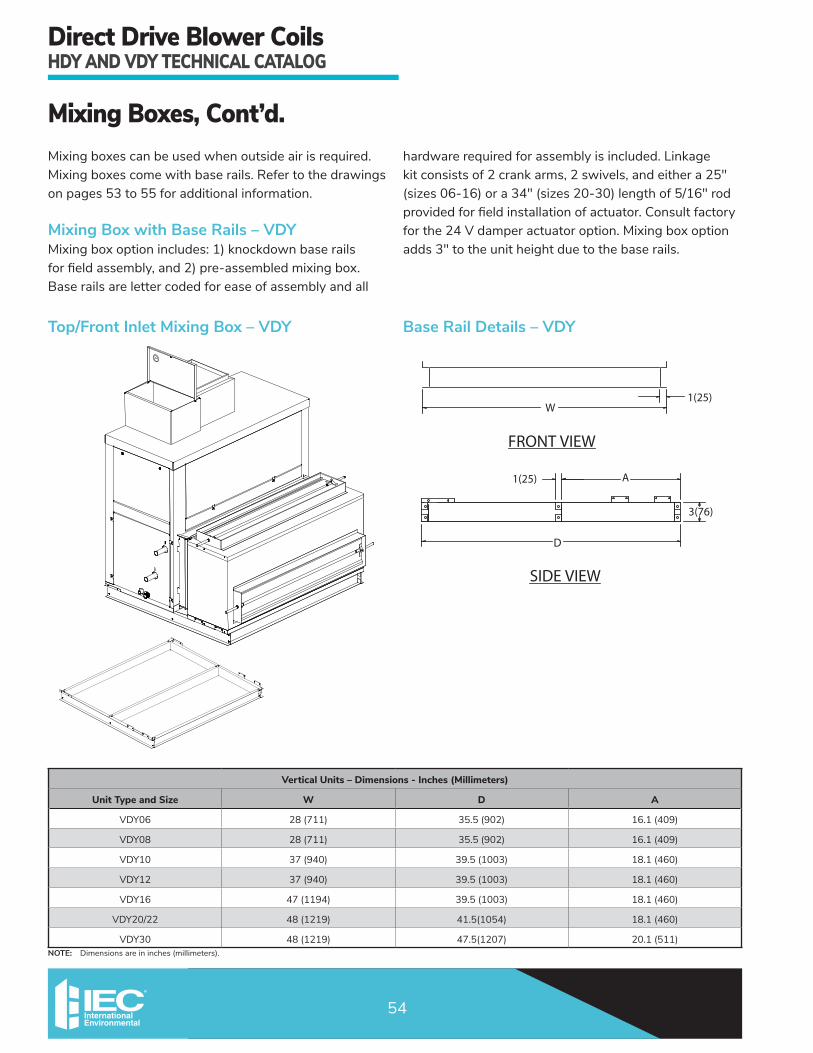
DirectDriveBlowerCoilsHDYANDVDYTECHNICALCATALOG
54
MixingBoxes,Cont’d.Mixingboxescanbeusedwhenoutsideairisrequired.Mixingboxescomewithbaserails.Refertothedrawingsonpages53to55foradditionalinformation.
Mixing Box with Base Rails – VDYMixingboxoptionincludes:1)knockdownbaserailsforfieldassembly,and2)pre-assembledmixingbox.Base rails are letter coded for ease of assembly and all
hardwarerequiredforassemblyisincluded.Linkagekitconsistsof2crankarms,2swivels,andeithera25"(sizes06-16)ora34"(sizes20-30)lengthof5/16"rodprovidedforfieldinstallationofactuator.Consultfactoryforthe24Vdamperactuatoroption.Mixingboxoptionadds3"totheunitheightduetothebaserails.
NOTE: Dimensionsareininches(millimeters).
1(25)W
FRONT VIEW
D
3(76)
A1(25)
SIDE VIEW
Base Rail Details – VDYTop/Front Inlet Mixing Box – VDY
Vertical Units – Dimensions - Inches (Millimeters)
Unit Type and Size W D A
VDY06 28(711) 35.5(902) 16.1(409)
VDY08 28(711) 35.5(902) 16.1(409)
VDY10 37(940) 39.5(1003) 18.1(460)
VDY12 37(940) 39.5(1003) 18.1(460)
VDY16 47(1194) 39.5(1003) 18.1(460)
VDY20/22 48(1219) 41.5(1054) 18.1(460)
VDY30 48(1219) 47.5(1207) 20.1(511)

DirectDriveBlowerCoilsHDYANDVDYTECHNICALCATALOG
55
MixingBoxes,Cont’d.
NOTE: 1. Dimensionsareininches(millimeters). 2. Add2”(51)tototalunitlengthifusing2”prefilteror4”filterwithmixingboxoption.
Mixing Box Details – HDY & VDY
Dimensions - Inches (Millimeters)
Unit Size H W A B C
06 18.5(470) 28(711) 6(152) 24(610) 11(279)
08 18.5(470) 28(711) 6(152) 24(610) 11(279)
10 20.25(514) 37(940) 8(203) 33(838) 13(330)
12 20.25(514) 37(940) 8(203) 33(838) 13(330)
16 20.25(514) 47(1194) 8(203) 43(1092) 13(330)
20/22 22.75(578) 48(1219) 8(203) 44(1118) 13(330)
30 31(787) 48(1219) 10(254) 44(1118) 15(381)
3(76)
A
C
2.4(61)
4(102)
H
2.4(61)
3(76)
1(25)
2(51)2(51)
WB
TOP VIEWS
BTM/REAR INLET - HDY TOP/REAR INLET - HDY
RIGHT HAND SIDE VIEWS
W
4(102)
2.4(61)
C
1(25)
H
A
A
B
A
2.4(61)

DirectDriveBlowerCoilsHDYANDVDYTECHNICALCATALOG
56
SerialPlateExample
INTERNATIONAL ENVIRONMENTAL CORP
Max Water Coil Leaving Air or Max Motor AMB:Max Fuse or Max Circ Breaker (HACR Type NEC):
Unit Intended for Indoor Use Only & Suited For 0.00 Clearance From Combustible Surfaces
-25A - SCCR: 5KA
Unit Serial No:Model No: HDY2000414324 776004-60-1
For Replacement Parts Call 1-866-432-7278
ELECTRICAL ENV/PERFMotor(s):
Motor VPH:Motor FLA:
Heater AMPS:
QTY of Motor(s):
Motor HP:Min Circ Amps:
Heater VPH:
E020-71537402
277/1/605.10A
18.1A5.0 kW
1
1 HP29.0A
277/1/60
Max ESP:Max Inlet Water Temp:
Coil Test:
High Side Coil Design:
Refrigerant Type:
1.65
300 PSIG
-
-
Max Outlet Air Temp:Max Hot Water or Steam:
ARI Model:
Low Side Coil Design:
-
HDY20B
-
190F
2 PSIG
Heater Kw:
Motor Current: 5.10A
Replacement Parts:
Manufactured in the USA

DirectDriveBlowerCoilsHDYANDVDYTECHNICALCATALOG
57
This page intentionally left blank.

DirectDriveBlowerCoilsHDYANDVDYTECHNICALCATALOG
58
This page intentionally left blank.

DirectDriveBlowerCoilsHDYANDVDYTECHNICALCATALOG
59
This page intentionally left blank.
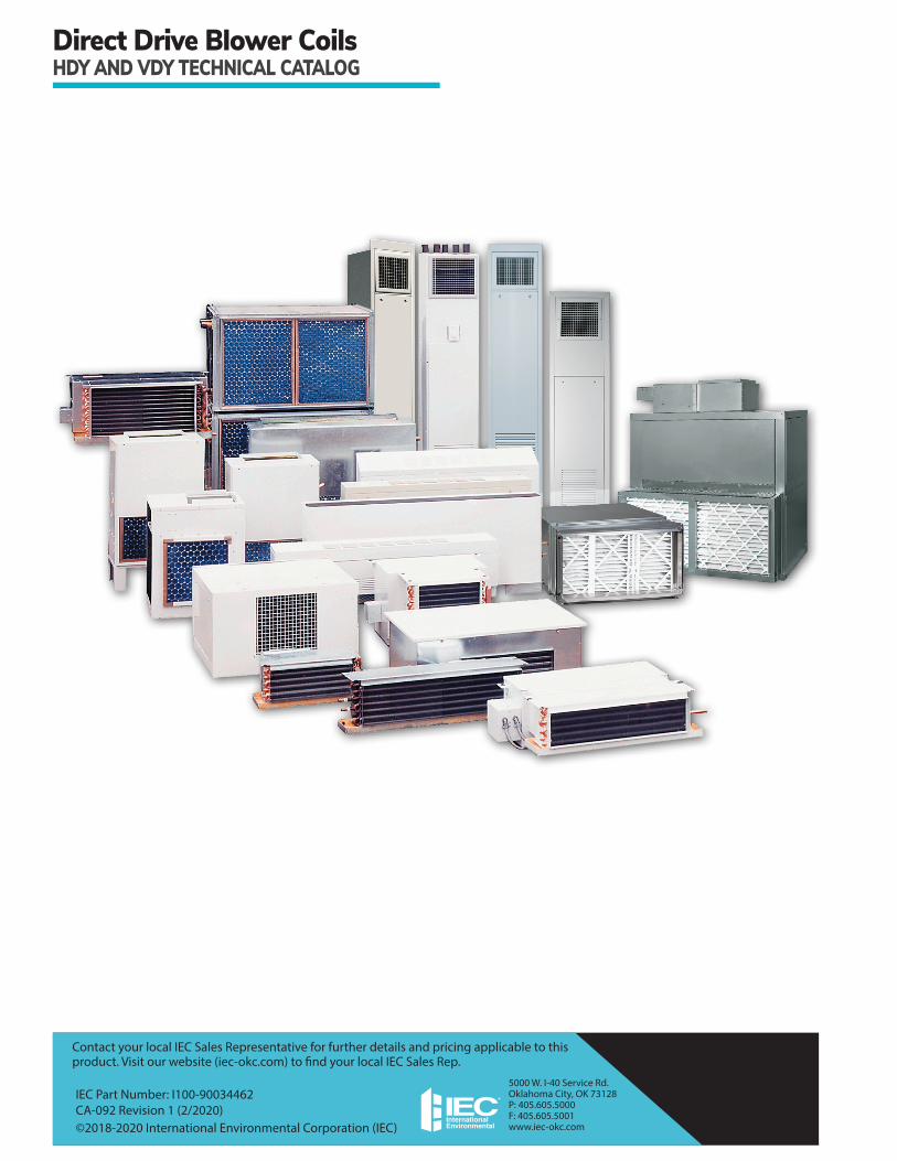
5000 W. I-40 Service Rd. Oklahoma City, OK 73128 P: 405.605.5000 F: 405.605.5001 www.iec-okc.com
DirectDriveBlowerCoilsHDYANDVDYTECHNICALCATALOG
Contact your local IEC Sales Representative for further details and pricing applicable to this product. Visit our website (iec-okc.com) to find your local IEC Sales Rep.
IEC Part Number: I100-90034462 CA-092 Revision 1 (2/2020) ©2018-2020 International Environmental Corporation (IEC)
Recommended