Division of Sport Fish Hatchery Evaluation–Anchorage Area
Hatcheries
Prepared for
Division of Sport Fish Alaska Department of Fish and Game
November 2004
301 West Northern Lights Boulevard, Suite 601
Anchorage, Alaska 99503-2691 (907) 278-2551

DIVISION OF SPORT FISH HATCHERY EVALUATION–ANCHORAGE AREA HATCHERIES III
Contents
Section Page
Contents.............................................................................................................................................. iii
Abbreviations................................................................................................................................... vii
Executive Summary............................................................................................................................ 1
Background.......................................................................................................................................... 1
Production Goals ................................................................................................................................ 1
Assessment of Existing Anchorage Area Hatcheries ................................................................... 1 3.1 Fort Richardson Hatchery .............................................................................................. 1
3.1.1 Aeration Building ............................................................................................ 1 3.1.2 Access Road...................................................................................................... 5 3.1.3 Broodstock Development Center .................................................................. 5 3.1.4 Broodstock Raceways ..................................................................................... 5 3.1.7 Outdoor Rearing Raceways ........................................................................... 7 3.1.8 Visitor Center ................................................................................................... 8 3.1.9 Operations Building........................................................................................ 8 3.1.10 Shop Building................................................................................................. 9 3.1.11 Water Treatment Building............................................................................ 9 3.1.12 Water Supply ................................................................................................. 9 3.1.13 Electrical Infrastructure .............................................................................. 10
3.2 Elmendorf Hatchery...................................................................................................... 12 3.2.1 Process Water Supply ................................................................................... 12 3.2.2 Power Plant Cooling Pond........................................................................... 15 3.2.3 Intake Building .............................................................................................. 15 3.2.4 Broodstock Raceways ................................................................................... 16 3.2.5 Generator Building........................................................................................ 16 3.2.6 Office/Incubation Building.......................................................................... 16 3.2.7 Degassing Building ....................................................................................... 16 3.2.8 Maintenance Shop ......................................................................................... 17 3.2.9 Raceways ........................................................................................................ 17 3.2.10 Summary of Existing Electrical Systems .................................................. 18
3.3 Existing Facilities Capability to Meet Current and Future Production Goals ...... 19 3.3.1 Schedule.......................................................................................................... 19
Fort Richardson Alternative Concept Plans .................................................................................. 1 4.1 Alternative I–New Recirculation Facility Concept Description ............................... 1
4.1.1 Geotechnical Assessment ............................................................................... 1 4.1.2 Site Evaluation ................................................................................................. 2

CONTENTS
IV DIVISION OF SPORT FISH HATCHERY EVALUATION–ANCHORAGE AREA HATCHERIES
4.1.3 Process Water Source ......................................................................................2 4.1.4 Fish-Rearing Areas...........................................................................................9 4.1.5 General Facility and Culture Systems Characteristics................................9 4.1.6 Effluent Treatment .........................................................................................14 4.1.7 Solids Waste Disposal ...................................................................................14 4.1.8 Offices and Administrative Areas ...............................................................14 4.1.9 Shop and Maintenance Area ........................................................................15 4.1.10 Building Services..........................................................................................15 4.1.11 Utility Tie-ins ................................................................................................15 4.1.12 Facility Power Supply, Distribution, and Controls.................................15 4.1.13 Building Mechanical Systems.....................................................................17 4.1.14 Ventilation.....................................................................................................17 4.1.15 Heating ..........................................................................................................18 4.1.16 Domestic Plumbing Systems......................................................................18 4.1.17 Architectural Code Analysis ......................................................................19 4.1.18 Lighting .........................................................................................................23 4.1.19 Architectural Elements................................................................................24 4.1.20 Required Permits..........................................................................................27
4.2 Alternative II–New Recirculation Module for Production of Catchables and Improvements to Existing Infrastructure .............................................................29 4.2.1 New Catchable Recirculation Module Description...................................29 4.2.2 Improvements to Existing Infrastructure ...................................................30 4.2.3 Electrical Power Supply, Distribution, and Controls................................35
Elmendorf Hatchery Visitor Center.................................................................................................1 5.1 Elmendorf Hatchery Visitor Center ..............................................................................1
Cost Estimates......................................................................................................................................1 6.1 Capital Costs.....................................................................................................................1 6.2 Annual Operational Costs Exclusive of Labor.............................................................1
6.2.1 Alternative I ......................................................................................................1 6.2.2 Alternative II.....................................................................................................1
References.............................................................................................................................................1 Appendix A Benefiting Alaska’s Economy: ADF&G’s Region II & III Recreational
Stocking Programs B Anchorage Hatchery Preliminary Cost Estimate, Alternative I C Anchorage Hatchery Preliminary Cost Estimate, Alternative II D Elmendorf State Hatchery Kiosk Construction Cost Estimate Figure 1-1 Vicinity Map ........................................................................................................................ 1-3 3-1 Fort Richardson Hatchery Existing Facilities.................................................................. 3-3
CONTENTS
DIVISION OF SPORT FISH HATCHERY EVALUATION–ANCHORAGE AREA HATCHERIES v
3-2 Fort Richardson Hatchery Electrical Site Plan...............................................................3-13 4-1 Fort Richardson Hatchery Improvements, Alternative I ...............................................4-3 4-2 Salmon Production Module, Alternative I.......................................................................4-5 4-3 Trout Production Module, Alternative I ..........................................................................4-7 4-4 Catchable Production Module, Alternative II ...............................................................4-31 4-5 Fort Richardson Hatchery Improvements, Alternative II............................................4-33 5-1 Proposed Upgrades.............................................................................................................5-3 Table
2-1 Region II Production Goals ................................................................................................2-1 2-2 Summary of Bioprogramming for the Anchorage Hatchery ........................................2-3 4-1 Planned Tank Dimensions ...............................................................................................4-10 4-2 Building 1–Design Occupant Load .................................................................................4-21 4-3 Building 2–Design Occupant Load .................................................................................4-21 4-4 Plumbing Fixture Quantities per Building ....................................................................4-22 4-5 Anticipated Noise Design Criteria ..................................................................................4-22 4-6 Lighting Level Standards .................................................................................................4-24

CONTENTS
VI DIVISION OF SPORT FISH HATCHERY EVALUATION–ANCHORAGE AREA HATCHERIES

DIVISION OF SPORT FISH HATCHERY EVALUATION–ANCHORAGE AREA HATCHERIES VII
Abbreviations
ADA Americans with Disabilities Act
ADEC Alaska Department of Environmental Conservation
ADF&G Alaska Department of Fish and Game
AL Aleknagik
Btu/h British thermal units per hour
°C degrees Celsius
cfm cubic feet per minute
cm/s centimeters per second
CO2 carbon dioxide
DO dissolved oxygen
DPW U.S. Army Department of Public Works
FF&E furniture, fixtures, and equipment
g gram
gpm gallons per minute
HDPE high-density polyethylene
hp horsepower
HVAC heating, ventilation, and air conditioning
IBC International Building Code
kV kilovolt
kVA kilovolt-ampere
kW kilowatt
LHO low head oxygenator
lpm liters per minute
LV low-voltage
m3 cubic meter
MCC motor control center
ML&P Municipal Light and Power

ABBREVIATIONS
VIII DIVISION OF SPORT FISH HATCHERY EVALUATION–ANCHORAGE AREA HATCHERIES
MV medium-voltage
PDS padmount distributor switch
PLC programmable logic controller
SC Ship Creek
SCADA Supervisory Control and Data Acquisition
USC United States Code
VAC volts alternating current
DIVISION OF SPORT FISH HATCHERY EVALUATION–ANCHORAGE AREA HATCHERIES ES-1
Executive Summary
The mission of the Alaska Department of Fish and Game (ADF&G) is “to protect, maintain, and improve fish, game, and aquatic plant resources of the State and to manage their useand development in the best interests of the economy and well being of the people of the state consistent with the sustained yield principle.”
The sport fish hatchery program plays an important part in meeting that responsibility. Each year this program produces and releases over 4 million fish at more than 200 locations to ensure that wild fish stocks remain healthy. This is accomplished through the development of alternative harvest opportunities that encourage anglers to focus more on stocked waters and closely managed fisheries. Nearly 80 percent of the annual production from the hatchery program remains in Southcentral Alaska. The remaining 20 percent are transported and released in the Fairbanks/Tanana area, mainly as larger (catchable) fish.
The National Survey of Fishing, Hunting, and Wildlife-Associated Recreation estimated that U.S. residents spent $537 million on fishing trips and equipment in Alaska in 2001. A more recent study conducted by Northern Economics (Appendix A) estimated that approximately $34 million of this benefit could be attributed to the ADF&G hatchery-stocking program. However, preservation of that benefit is now in serious jeopardy.
The Elmendorf and Fort Richardson hatcheries (located in Anchorage) have traditionally been responsible for nearly all of the sport fish enhancement production for Southcentral and Interior Alaska. Both facilities have historically relied on an abundance of waste heat extracted from the Elmendorf Air Force and Fort Richardson Army base power plants to accelerate fish growth. The Fort Richardson power plant went cold in March of 2004 and the Elmendorf power plant is scheduled to go offline in 2005. The loss of heat, coupled with the aging infrastructure of both facilities, puts the current production program in jeopardy and makes expanding the program impossible. Recognizing this, the Division of Sport Fish has initiated an evaluation of its hatchery program to determine the most cost-effective manner to continue supporting sport fish management and hatchery production for the next 20 years and beyond.
Future production needs and facility options to meet the growing demand for sport fish in Alaska were assessed. During the course of this work, previous hatchery evaluations were reviewed, inspections of facilities conducted, and operational personnel interviewed. It was determined that a new hatchery in Fairbanks is one part of the solution. However, it is critically important that new hatchery facilities also be constructed in Southcentral Alaska. Two alternative design solutions for facility upgrades to the Fort Richardson hatchery have been developed. Both design solutions result in closing the Elmendorf hatchery with the exception of Chinook and Coho broodstock capture and holding activities. Also proposed is the construction of a visitor center/fish viewing area at the Elmendorf site. These two selected alternatives are as follows:
• Alternative I: Design and Construction–This alternative proposes building two new recirculation fish production facilities, replacing existing facilities. The facilities include
EXECUTIVE SUMMARY
ES-2 DIVISION OF SPORT FISH HATCHERY EVALUATION–ANCHORAGE AREA HATCHERIES
new ancillary facilities and utilities, with the exception of the well systems. The design solution concept would utilize approximately 1,600 gallons per minute (gpm) of water, well within the amounts currently supplied by the existing hatchery well fields (3,500 gpm). Estimated cost of this alternative for design and construction is $45 million.
• Alternative II: Design and Construction–This alternative proposes retaining and enclosing existing raceways, remodeling ancillary buildings, upgrading site utilities, and building one new recirculation facility. This alternative would utilize all of the existing hatchery process water supply and require an additional 500 gpm for the new catchable module. The additional water would likely come from new wells drilled in the vicinity of the hatchery. Estimated cost of this alternative for design and construction is $25 million.
Both alternatives provide for continued production at current program goals. Alternative I is designed for an expansion of production to meet future goals over the next 20 years. Alternative II, while requiring less capital expenditure than Alternative I, requires much more process water for operation, increases operational costs, and depends upon additional water supplied from a limited aquifer. Both alternatives are dependent upon the continued availability of hatchery land from the U.S. Army. Without implementing one of these alternatives (or others not considered in this study) the hatchery will be unable to meet current or future production goals after the closure of the Elmendorf power plant in 2005.
DIVISION OF SPORT FISH HATCHERY EVALUATION–ANCHORAGE AREA HATCHERIES 1-1
SECTION 1
Background
The Alaska Department of Fish and Game (ADF&G) Division of Sport Fish initiated this evaluation of its hatchery program to determine the most cost-effective manner to continue supporting sport fish management and hatchery production for the next 20 years and beyond. In recent years, the Elmendorf and Fort Richardson hatcheries (located in Anchorage) have been responsible for most of the sport fish enhancement production in Southcentral and Interior Alaska. Their combined annual production of more than 4 million salmon, trout, char, and grayling supports the mission of the Division of Sport Fish to protect and improve Alaska’s recreational fisheries resources. Creel census data shows that approximately 75 percent of all rainbow trout harvested in the state of Alaska and 20 percent of all Chinook salmon harvested in Southcentral Alaska are hatchery fish. Production is limited by hatchery capacity, warm water accessibility, stock availability, genetics, diseases, and funding.
The Division of Sport Fish has been monitoring angler effort since 1977 when 950,616 angler days were recorded in the Southcentral and Interior areas. By the year 2000 the effort had more than doubled, growing to 2,680,639 angler days. The growth in effort tracks closely with the harvest and catch figures. However, it is worth noting that although the number of angler days has not grown significantly since 1990, there has been a shift in non-resident angling, which now exceeds the level of resident angling and continued growth in tourism is expected. Although it would appear that the effort has stabilized for the near term, angling pressure on wild stocks has reached the limit for sustained yield. Local stocks such as rainbow trout, Chinook, and Coho salmon are increasingly impacted as residents and visitors enjoy freshwater angling as a recreational choice. Over the past 10 years, harvest regulations have become more and more restrictive in an attempt to protect wild stocks. The sport fish hatchery program helps to ensure that these wild stocks remain abundant by providing alternative harvest opportunities that allow anglers to focus more on stocked waters. The National Survey of Fishing, Hunting, and Wildlife-Associated Recreation estimated that U.S. residents spent $537 million on fishing trips and equipment in Alaska in 2001. A recent study conducted by Northern Economics estimated that approximately $34 million of those dollars are attributed to the ADF&G stocking program. The Division of Sport Fish is evaluating future production needs and facility options for growing resource requirements. Long-term goals include improving public access and educational opportunities at the state hatcheries and expanding production capability to meet the future demand for sport fish.
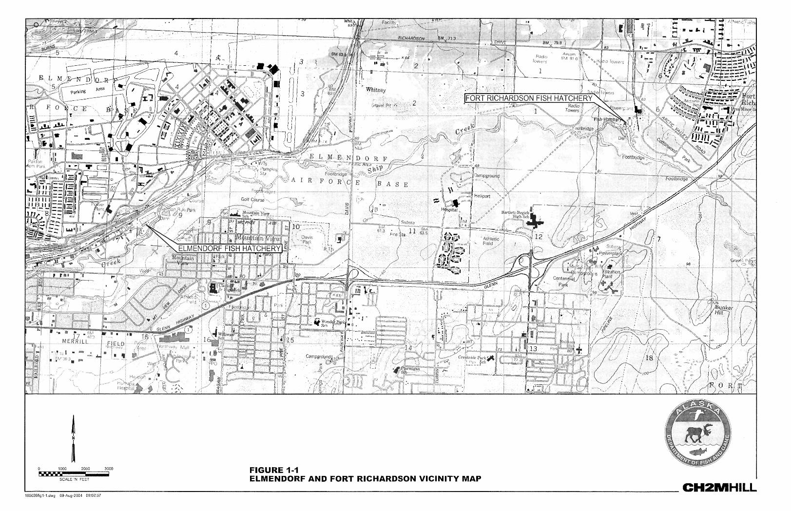
Two Anchorage-based hatcheries, one at Fort Richardson and one at Elmendorf Air Force Base (Figure 1-1), have been centers of sport fish production since the 1950s and over the years have absorbed fish production programs resulting from closure of other State of Alaska sport fish hatcheries. Fish production from these hatcheries has been used to supplement existing natural production and create new fisheries where none previously existed.
BACKGROUND
1-2 DIVISION OF SPORT FISH HATCHERY EVALUATION–ANCHORAGE AREA HATCHERIES
In order to meet ever-increasing production demands, ADF&G has, over the years, incrementally upgraded the Fort Richardson and Elmendorf hatcheries to improve production capabilities and increase operational efficiencies. However, both facilities still have critical deficiencies that limit the flexibility of operations and fish production potential. Presently the most critical limiting factor is the loss of a free source of waste heat. Both facilities have historically relied upon abundant quantities of waste heat from the Elmendorf and Fort Richardson power plants to accelerate fish growth. The Fort Richardson power plant ceased operations in March of 2004, and the Elmendorf power plant is expected to go offline in 2005. A second limiting factor is the availability of pathogen-free water in sufficient quantities to ensure disease-free production during all stages of incubating and rearing fish stocks.
Although these hatcheries have been able to meet production goals in the past, the original design of the facilities, combined with limitations of quality water, pending loss of free waste heat and aging and deteriorating infrastructure, have so greatly compromised productivity that it is presently impossible to meet existing demands. Major upgrade or replacement of the facilities will be necessary in order to meet current as well as future production goals. ADF&G management recognizes that there is a pressing need for action to enable the Division of Sport Fish to seek alternative strategies to continue with their mission.
Currently, Anchorage-area hatcheries support all Division of Sport Fish production for both Regions II (Southcentral) and III (Interior). Centralized production can provide an economy of scale but can also present significant transportation logistics (and costs) associated with stocking.
Development of a new Fairbanks hatchery to take over fish production for Interior Alaska stocking projects has been proposed as a key element in the overall planning for the future of the hatchery program. The scope of this project is discussed in detail in a separate document, Proposed Fairbanks Fish Hatchery, Project Description (CH2M HILL, 2004). For planning purposes for the Anchorage area hatchery improvements, the Fairbanks facility is assumed to be operational by 2008.
In order to maximize available resources, this feasibility assessment will be focused on both ends of the spectrum: (1) complete new facility, which will meet current and future production goals; or (2) perform minimal required repairs and upgrades to enable the existing hatchery infrastructure to maintain current production goals. The culmination of this feasibility study is Rough-Order-of-Magnitude cost estimates for each of these options.
DIVISION OF SPORT FISH HATCHERY EVALUATION–ANCHORAGE AREA HATCHERIES 2-1
SECTION 2
Production Goals
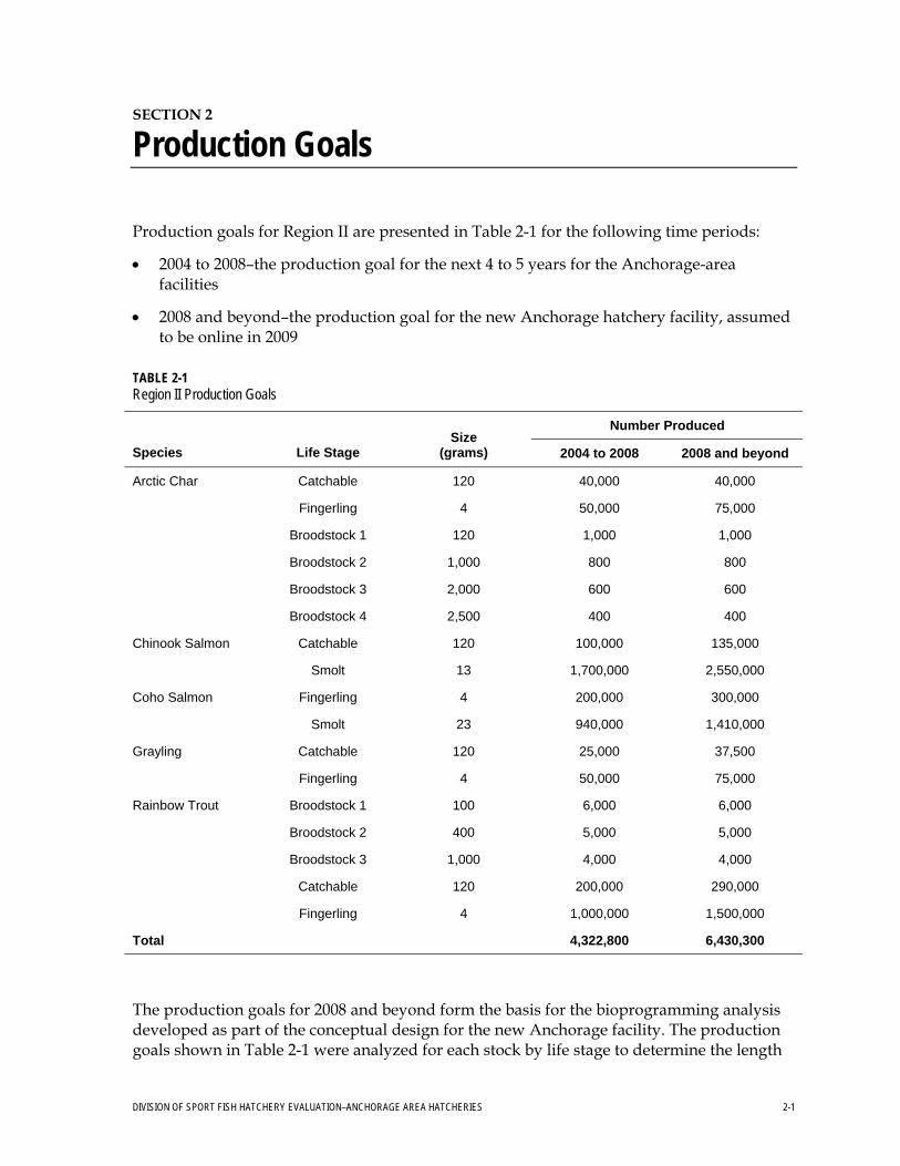
Production goals for Region II are presented in Table 2-1 for the following time periods:
• 2004 to 2008–the production goal for the next 4 to 5 years for the Anchorage-area facilities
• 2008 and beyond–the production goal for the new Anchorage hatchery facility, assumed to be online in 2009
TABLE 2-1 Region II Production Goals
Number Produced
Species Life Stage Size
(grams) 2004 to 2008 2008 and beyond
Arctic Char Catchable 120 40,000 40,000
Fingerling 4 50,000 75,000
Broodstock 1 120 1,000 1,000
Broodstock 2 1,000 800 800
Broodstock 3 2,000 600 600
Broodstock 4 2,500 400 400
Chinook Salmon Catchable 120 100,000 135,000
Smolt 13 1,700,000 2,550,000
Coho Salmon Fingerling 4 200,000 300,000
Smolt 23 940,000 1,410,000
Grayling Catchable 120 25,000 37,500
Fingerling 4 50,000 75,000
Rainbow Trout Broodstock 1 100 6,000 6,000
Broodstock 2 400 5,000 5,000
Broodstock 3 1,000 4,000 4,000
Catchable 120 200,000 290,000
Fingerling 4 1,000,000 1,500,000
Total 4,322,800 6,430,300
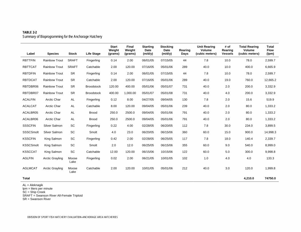
The production goals for 2008 and beyond form the basis for the bioprogramming analysis developed as part of the conceptual design for the new Anchorage facility. The production goals shown in Table 2-1 were analyzed for each stock by life stage to determine the length

PRODUCTION GOALS
2-2 DIVISION OF SPORT FISH HATCHERY EVALUATION–ANCHORAGE AREA HATCHERIES
of rearing, water requirements, tank sizes required, and stocking dates. Table 2-2 summarizes this information.
DIVISION OF SPORT FISH HATCHERY EVALUATION–ANCHORAGE AREA HATCHERIES
TABLE 2-2 Summary of Bioprogramming for the Anchorage Hatchery
Label Species Stock Life Stage
Start Weight(grams)
Final Weight (grams)
Starting Date
(m/d/y)
Stocking Date
(m/d/y) Rearing
Days
Unit Rearing Volume
(cubic meters)
# of Rearing Vessels
Total Rearing Volume
(cubic meters)
Total Flow (lpm)
RBTTFIN Rainbow Trout SRAFT Fingerling 0.14 2.00 06/01/05 07/15/05 44 7.8 10.0 78.0 2,599.7
RBTTCAT Rainbow Trout SRAFT Catchable 2.00 120.00 07/16/05 05/01/06 289 40.0 10.0 400.0 6,665.9
RBTDFIN Rainbow Trout SR Fingerling 0.14 2.00 06/01/05 07/15/05 44 7.8 10.0 78.0 2,599.7
RBTDCAT Rainbow Trout SR Catchable 2.00 120.00 07/16/05 05/01/06 289 40.0 19.0 760.0 12,665.2
RBTDBR06 Rainbow Trout SR Broodstock 120.00 400.00 05/01/06 05/01/07 731 40.0 2.0 200.0 3,332.9
RBTDBR07 Rainbow Trout SR Broodstock 400.00 1,000.00 05/01/07 05/01/08 731 40.0 4.0 200.0 3,332.9
ACALFIN Arctic Char AL Fingerling 0.12 8.00 04/27/05 09/04/05 130 7.8 2.0 15.6 519.9
ACALCAT Arctic Char AL Catchable 8.00 120.00 09/04/05 05/01/06 239 40.0 2.0 80.0 1,333.2
ACALBR05 Arctic Char AL Brood 250.0 2500.0 09/04/05 05/01/06 791 40.0 2.0 80.0 1,333.2
ACALBR06 Arctic Char AL Brood 250.0 2500.0 09/04/05 05/01/06 791 40.0 2.0 80.0 1,333.2
SSSCFIN Silver Salmon SC Fingerling 0.22 4.00 02/28/05 06/20/05 112 7.8 30.0 234.0 3,899.5
SSSCSmolt Silver Salmon SC Smolt 4.0 23.0 06/20/05 06/15/06 360 60.0 15.0 900.0 14,998.3
KSSCFIN King Salmon SC Fingerling 0.42 2.00 02/28/05 06/25/05 117 7.8 18.0 140.4 2,339.7
KSSCSmolt King Salmon SC Smolt 2.0 12.0 06/25/05 06/15/06 355 60.0 9.0 540.0 8,999.0
KSSCCAT King Salmon SC Catchable 12.00 120.00 06/15/06 10/15/06 122 60.0 5.0 300.0 9,998.8
AGLFIN Arctic Grayling Moose Lake
Fingerling 0.02 2.00 06/21/05 10/01/05 102 1.0 4.0 4.0 133.3
AGLMCAT Arctic Grayling Moose Lake
Catchable 2.00 120.00 10/01/05 05/01/06 212 40.0 3.0 120.0 1,999.8
Total 4,210.0 74750.0
AL = Aleknagik lpm = liters per minute SC = Ship Creek SRAFT = Swanson River All-Female Triploid SR = Swanson River

PRODUCTION GOALS
2-4 DIVISION OF SPORT FISH HATCHERY EVALUATION–ANCHORAGE AREA HATCHERIES
DIVISION OF SPORT FISH HATCHERY EVALUATION–ANCHORAGE AREA HATCHERIES 3-1
SECTION 3
Assessment of Existing Anchorage Area Hatcheries
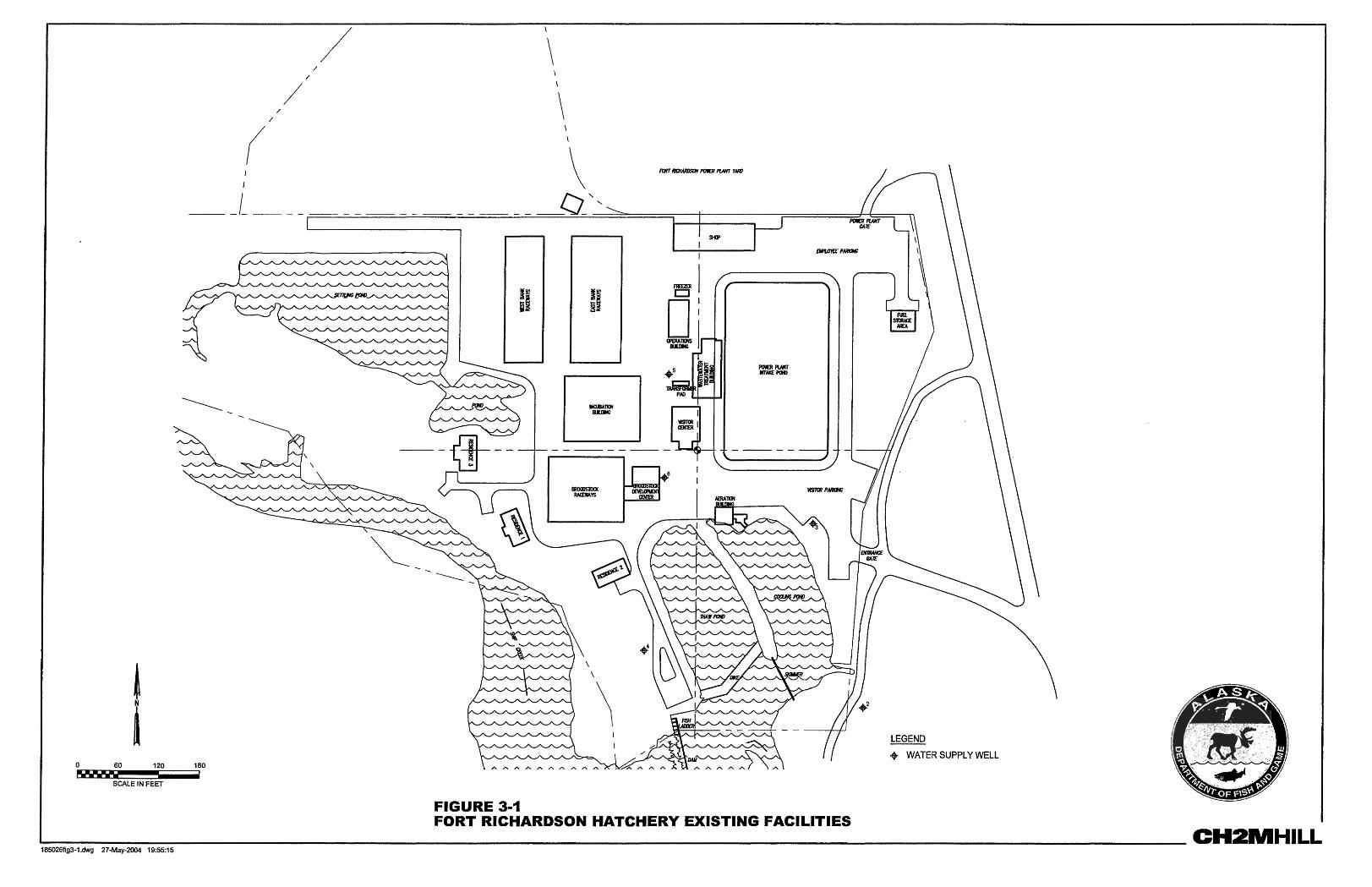
One function of the program for concept development of improvements to the Anchorage-area hatcheries was an initial assessment of existing facilities (Figure 3-1). This assessment consisted of a physical inspection of the two existing Anchorage facilities and a review of the following key documents:
• Fisheries Bioengineering Services for Hatchery Evaluation and Water Use/Water Treatment Recommendations: Elmendorf State Fish Hatchery ADF&G, Sport Fish Division, March 2002, prepared by The Conservation Fund Freshwater Institute
• Fisheries Bioengineering Services for Hatchery Evaluation and Water Use/Water Treatment Recommendations: Fort Richardson State Fish Hatchery, ADF&G, Sport Fish Division, February 2002, prepared by The Conservation Fund Freshwater Institute
• Fort Richardson Heated Water Pipeline Study–Preliminary Design Report, August 2003, prepared by HDR Alaska, Inc.,
Physical inspections of the Anchorage-area hatcheries were conducted in early 2004 to inventory and assess the condition of the facilities, including fish production equipment, process water systems, electrical and mechanical systems, and building infrastructure. The following paragraphs summarize results of this inspection.
3.1 Fort Richardson Hatchery 3.1.1 Aeration Building The Aeration Building is the collection point for the hatchery water supply, which comes from 10 near-field and 11 far-field groundwater wells. Maximum water supply from the well fields is approximately 2,500 to 3,500 gallons per minute (gpm). Water is piped into the Aeration Building cold-water sump from the wells. The Aeration Building serves the following functions:
• Water is aerated to remove supersaturated levels of dissolved gases • Level of oxygen is increased
As much as 1,100 gpm of the water is heated to 14 degrees Celsius (°C) to provide the means to increase the growth rate of some of the fish.
Cold water is pumped from the cold-water sump to an aeration column (a 12-foot-tall aluminum tower housing several layers of screens with an open-air interface) on the roof of the structure. The water falls through the column and then is gravity fed to the hatchery fish-rearing systems. The tower is able to reduce elevated gas saturation levels within the
ASSESSMENT OF EXISTING ANCHORAGE AREA HATCHERIES
3-2 DIVISION OF SPORT FISH HATCHERY EVALUATION–ANCHORAGE AREA HATCHERIES
water to as low as 101 percent, thus reducing the effects of gas bubble trauma in fish rearing stocks.
As much as 1,100 gpm of the water can be pumped from the cold-water sump to the heat exchanger side of the building and into plate and frame heat exchangers where the water can be heated up to 14°C. The hot-water loop of the heat exchangers is heated by as many as six natural-gas-fired boilers with a combined capacity of 12 million British thermal units. These boilers were recently added to the system to partially make up for the waste heat lost to the facility when the Fort Richardson power plant shut down.
Water warmed in the heat exchangers is then pumped to a warm-water aeration tower on the aeration side of the building and gravity fed to the hatchery’s fish-rearing systems.
Currently, an overflow from the cold-water sump diverts excess supply water from the Aeration Building to Ship Creek.
It should be noted that the belowground piping that distributes water from the Aeration Building to the rearing areas of the hatchery is in very poor condition due mainly to corrosion and needs replacement in the very near term. It has also recently been noted (8/23/04) that the upper sump cracking is getting worse and an immediate repair is necessary to stop the flow of water into the aeration pump room. This recent discovery may make replacement of the Aeration Building rather than repair a desirable option.
3.1.1.1 Structure/Architecture The corrugated metal roof on the heat exchange side is leaking, and icing problems may be aggravating the leaks. This roof needs to be replaced. On the aeration side, water from the roof sump is leaking through cracks in the concrete roof, causing corrosion on pumps in the aeration room. These cracks should be grouted and sealed. Water was on the floor during the site visit conducted January 23, 2004, and this problem is reportedly getting worse. Some ice damage to the aeration towers was also noted during the site visit. The aeration towers are enclosed on all four sides by a chain-link fence with cedar slats, but gaps in the fencing and the open top allow for disease-carrying vectors to contact the water supply at this location. An improved enclosure for this area is recommended.
The doors on the north side of the structure are in disrepair, and the access stairs and platform do not conform to current building codes.
3.1.1.2 Mechanics/Heating, Ventilation, and Air Conditioning This hatchery structure contains process equipment such as boilers, heat exchangers, pumps, piping, and aeration towers. The boiler/heat exchanger room is heated by two gas-fired, horizontal unit heaters, newer Trane models with remote thermostat control that appear to be in good condition. A single electric unit heater provides heat for the Aeration Building pump room (between the upper and lower sumps). This is a Q-Mark 10-kilowatt (kW) vertical unit heater in fair condition but may be undersized for the required heating load. A supply air fan serves the boiler area but was not operating at the time observed. An outside air (relief) opening exists in the boiler area. The boilers themselves are sealed combustion units with dedicated outside air intakes. An investigation is recommended to determine if another air combustion opening is required to serve the unit heaters.
ASSESSMENT OF EXISTING ANCHORAGE AREA HATCHERIES
DIVISION OF SPORT FISH HATCHERY EVALUATION–ANCHORAGE AREA HATCHERIES 3-5
3.1.2 Access Road The hatchery access road is surfaced with gravel with high fines content. During summer months, dust from the access road clogs the air filter on the boilers in the Aeration Building and causes inefficient operation of the boilers. This is a maintenance problem. The existing access road and parking area adjacent to the Aeration Building should be paved to reduce dust entering the Aeration Building boiler air intake.
The unsurfaced roads are also a problem for keeping the Operations Building clean because operators track dirt into the building. Paving around the Operations Building would help this situation.
3.1.3 Broodstock Development Center The purpose of the Broodstock Development Center is broodstock production and growth. This building also houses the hatchery laboratory, which is necessary to conduct fish health investigations. Trout and char are incubated, reared and held as adults for egg production. The building is a 2,000-square-foot, wood-frame building on a reinforced concrete slab with textured plywood siding and metal roof. Fish are reared in circular tanks within the heated building for the first year, and then moved to outdoor raceways adjacent to the building. Currently no temperature variation control exists for the different species within outdoor rearing units, which is not optimal for fish health or growth.
3.1.3.1 Structure/Architecture The building structure is in fair condition with no major problems noted. The laboratory floor requires resurfacing, and OSHA-approved facilities for chemical storage are recommended. There is significant water damage to one exterior wall and one interior wall as a result of water leaks.
3.1.3.2 Mechanics/Heating, Ventilation, and Air Conditioning A single air handler unit provides heated outside air through a sheet metal distribution ductwork and supply diffusers serve the incubation/rearing tank room and laboratory. This unit is manufactured by Jackson & Church, with a gas-fired furnace section (313,000-British-thermal-units-per-hour [Btu/h] input, 250,000-Btu/h output) and a 2-horsepower (hp), 208-volt, 3-phase blower with 4,160-cubic-feet-per-minute (cfm) capacity. The handler unit is in fair condition and appears to be operating properly. Also located in the incubation/ rearing tank room is a gas-fired horizontal unit heater, manufactured by Modine, with a gas input rating of 75,000 Btu/h. A similar gas-fired unit heater heats the egg-take area. Both are newer models in good condition.
The restroom includes a water closet and lavatory and is served by a small exhaust fan ducted to outdoors. An electric, tank-type hot-water heater, 17-gallon storage capacity with a single 4,500-watt 208-volt heater element, provides domestic hot water.
3.1.4 Broodstock Raceways Nine broodstock raceways are located outdoors as an extension of the Broodstock Development Center. These raceways are used to raise 2- and 3-year-old rainbow trout and arctic char. The raceways are also used for trout and char broodstock holding. Broodstock

ASSESSMENT OF EXISTING ANCHORAGE AREA HATCHERIES
3-6 DIVISION OF SPORT FISH HATCHERY EVALUATION–ANCHORAGE AREA HATCHERIES
raceways use water warmed to approximately 10 °C from March 15 to October 1 to increase growth and induce spawning. After October 1, the broodstock raceways use water at ambient temperatures of 2 to 7°C. The raceways are concrete structures 10 feet wide by 100 feet long, with water depth of approximately 2.5 feet. The water flow of 800 to 900 gpm in these raceways yields velocity of 2.2 to 2.5 centimeters per second (cm/s). Flow rate of 1,200 gpm to yield a velocity of 4 cm/s is required for self-cleaning; therefore, the current water velocity is less than ideal for removing solids from the raceways. Periodic brushing and flushing removes solids. The solids from the raceways gravity feed to the settling pond during cleaning when the mud valve at the end of each raceway is opened. Reuse pumps have been installed to return some of the water in the raceways to the head of the raceways to increase the velocity of water in the raceways and increase the amount of oxygen in the water. However, optimal velocities are still not achieved.
In contrast to other outdoor raceways, the concrete in the broodstock raceways appears to be relatively smooth surfaced and in good shape; however, the continued use of outdoor raceways exposes operators to conditions that pose dangers to personnel from snow and ice, low water temperatures, and even lower air temperatures. Operating the broodstock raceways also exposes the fish to several possible biosecurity risks from birds and small mammals that enter the raceways. During the site visit, the operators mentioned that a covered facility would significantly reduce maintenance and personnel safety risks as well as improve fish health. This would clearly be a significant improvement over the current hatchery configuration.
3.1.5 Egg-Take Area Integral to the broodstock building is the egg-take facility. Housed within the rear portion of the structure is a large room with a concrete sump that can be partitioned into several holding areas. During egg take, water from the Aeration Building is fed into this sump, and the water exhausts out of the building via a fish ladder to the headrace in front of the broodstock raceways. The broodstock facility is designed to allow volitional passage of the broodstock up the ladder to the egg-take area. However, in the interest of efficiency, the fish are now collected below the ladder and brailed into the upper concrete sump for sorting and egg collection. Females are spawned using pressurized oxygen, which is introduced into the body cavity using a large diameter hypodermic needle. The oxygen is “valved in” using a modified automotive tire inflator at a pressure of 0.5 pounds per square inch delivered through a hose from an oxygen tank. The oxygen entering the body displaces the ripe eggs, now free from the skeins, and the eggs are ejected from the brood hen through the cloaca and into a bowl. Sperm from ripe males is squeezed from the body of a male trout and the stream of milt is directed into the egg-filled bowls, where fertilization occurs. A small amount of water is added to the bowl to activate the sperm, and the sperm/egg mixture is gently agitated. After fertilization, the eggs are moved into the incubation room in the Incubation and Indoor Raceway Building.
3.1.6 Incubation Building The 8,500-square-foot Incubation Building houses a separate incubation room and 24 indoor raceways in the main open area. Trout and char eggs collected and fertilized at the Broodstock Building and eggs collected from wild stocks at remote locations are transferred to the incubation room and placed into Heath Trays (200 trays in 40 stacks). The eggs are

ASSESSMENT OF EXISTING ANCHORAGE AREA HATCHERIES
DIVISION OF SPORT FISH HATCHERY EVALUATION–ANCHORAGE AREA HATCHERIES 3-7
incubated for varying lengths of time before hatching. The newly hatched fry are then transferred to the indoor raceways for rearing. The fry are raised in the indoor raceways for 4 months, then moved to the outdoor raceways or transferred off site. One circular tank is presently being used as an experimental rearing tank for a recirculation system to evaluate the performance of intense recycle technology as the future of the hatchery program.
The indoor raceways use first-pass ambient and heated water nearly all year round. Each raceway has a dual drain system that allows water to be directed to either the settling pond or a collection sump. All effluent from the indoor rearing units is now sent to the hatchery settling pond before discharge into Ship Creek. All of the indoor raceways are fitted with reuse pumps, vacuum degassing columns and micro-bubble diffused oxygen supply.
3.1.6.1 Structure/Architecture The building is wood frame with wood siding and a metal roof and generally appears to be in good shape. Several roof leaks were noted during the site visit and appear to be associated with roof penetrations. Roof icing problems were also noted. Some of the interior raceways were leaking during the site visit. According to operators, controlling leaking raceways is an ongoing maintenance concern.
3.1.6.2 Mechanics/Heating, Ventilation, and Air Conditioning Six gas-fired, horizontal unit heaters serve the main space. All are suspended from the ceiling and vented through the roof. They appear to be in good condition. A single air handler provides ventilation and additional heating for the facility. The unit is manufactured by Jackson & Church, with a gas-fired furnace section (500,000-Btu/h input, 400,000-Btu/h output) and a 5-hp, 480-volt, 3-phase blower with 7,300-cfm capacity. Modulating outside air and return air dampers control the ventilation rate. The handler unit is in fair condition and appears to be operating properly. Supply air is distributed through sheet metal ductwork and overhead supply diffusers. Relief air exits the building through ducted openings with inlets near floor level.
3.1.7 Outdoor Rearing Raceways Twenty-four outdoor rearing raceways are used to raise fish to target size after early rearing in the Incubation Building. The east bank has four parallel groups of four serial reuse raceways that are currently being used to produce approximately 1.7 million 13-gram (g) Chinook salmon. These raceways receive 1,000 gpm of fresh well water (250 gpm per bank) that is mixed with 3,200 gpm of reuse water (800 gpm per bank), pumped from the tail of each fourth-pass raceway to the head of each first-pass raceway. The west bank has two parallel groups of four serial reuse raceways that are used to raise approximately 4-g Coho salmon fingerling to smolt size (about 23 g). These raceways use cold, ambient-temperature water year round and operate at a 50 percent reuse rate.
The outdoor raceways are concrete structures 8 feet wide by 80 feet long with water depth of approximately 2.5 feet. Each raceway receives approximately 1000 gpm of water flow, which is less than required to effectively remove solid wastes. Each raceway has the ability to collect water at the tail end and pump a portion of the water into an aeration tower to aerate the water before it passes to the next raceway behind it. The raceways are configured so that water passes through four raceways before it can be exhausted, though the water can
ASSESSMENT OF EXISTING ANCHORAGE AREA HATCHERIES
3-8 DIVISION OF SPORT FISH HATCHERY EVALUATION–ANCHORAGE AREA HATCHERIES
be drained after each of the first three passes. Each raceway has dual-drain system. Water can be directed through the use of two differing height standpipes to either the settling pond or to the power plant cooling pond. Solids are removed and directed to the settling pond via a standpipe in specially designed settling zones at the end of each raceway.
These raceways are 21 years old. Pitting and cracking was observed during site visits in 2004. According to hatchery operators, lots of cracks and leaks exist in the raceways. The cracks and leaks create ongoing maintenance issues for operators, including weed growth, glaciation, and concerns about raceway integrity. Continued use of outdoor raceways exposes operators to conditions that pose dangers from snow and ice, low water temperatures, and low air temperatures. Operating outdoor raceways also exposes fish to several possible biosecurity risks from birds and small mammals that enter the raceways. During the site visit, the operators mentioned that a covered facility would significantly reduce maintenance and personnel safety risks and increase fish health.
3.1.8 Visitor Center The visitor center contains a large meeting room, an office, a storage/mechanical area, restrooms, and an entrance desk. The building houses various informational displays and can be used to provide visitors with information regarding hatchery operations. Heightened security measures that have recently been implemented due to world events make access to the Fort Richardson hatchery difficult, at best. Under current security measures, this building does not serve the visitor information function. Many of the hatchery personnel have desks and computer stations in the visitor center.
3.1.8.1 Structure/Architecture The building is a 2,300-square-foot, wood-framed building with textured wood siding and a metal roof. No major structural problems were noted for this building. Renovations are not required but would improve the building appearance and functionality.
3.1.8.2 Mechanics/Heating, Ventilation, and Air Conditioning A gas-fired, forced-air furnace heats all areas. The unit is an American Standard Freedom 80 model and is in good operating condition. The restrooms each have one water closet and lavatory; the men’s room also has two urinals. Domestic hot water is provided by an electric, tank-type hot water heater, 30-gallon storage capacity with dual 2,500-watt, 208-volt heater elements.
3.1.9 Operations Building The Operations Building houses offices, lunchroom/meeting room, lockers, and showers for hatchery staff and serves as a control center for hatchery operations. Three staff members currently use the building. The building is a simple, wood-frame structure on slab with wood siding and a metal roof. No major structural problems were noted for this building, but the interior needs renovation at a minimum. The facility is heated by a gas-fired boiler with baseboard registers and hydronic unit heaters. The system is currently operating, but capacity and condition are unknown.
Tracking of dirt from the unpaved areas surrounding the building is an ongoing problem. Paving the area around the building should help this situation.
ASSESSMENT OF EXISTING ANCHORAGE AREA HATCHERIES
DIVISION OF SPORT FISH HATCHERY EVALUATION–ANCHORAGE AREA HATCHERIES 3-9
3.1.10 Shop Building The purpose of the Shop Building is for vehicle and equipment maintenance and cold storage. The Shop/Maintenance Building is made up of three garage-type bays and a cold storage area. Typical activities include steel fabrication, woodwork, and small equipment repair.
3.1.10.1 Structure/Architecture The building is a 4,100-square-foot, wood frame on slab with wood siding and a metal roof. Large garage doors access the three large maintenance bays. The eastern bay does not have a concrete floor, which is an inconvenience for operators. Observation of the building trusses indicates that an analysis should be conducted to verify the trusses can support current code snow loads.
3.1.10.2 Mechanics/Heating, Ventilation, and Air Conditioning Two gas-fired, horizontal unit heaters serve the first two bays. One is a Modine unit, with 75,000-Btu/h capacity, in good condition. The second is a smaller unit, manufacturer and capacity unknown. The third bay and the cold storage area are unheated. The second bay is designated for welding operations and includes a sidewall propeller exhaust fan, in fair condition. Assuming that welding takes place frequently, this small fan does not provide adequate ventilation to meet code requirements.
3.1.11 Water Treatment Building Construction of the Water Treatment Building was completed in 1998, but due to equipment incompatibility and resource supply problems that proved to be insurmountable, the facility does not serve the original intended function. Currently, water flowing from the East Bank raceways flows to the Water Treatment Building but is then bypassed to the large settling pond. The building is a 3,000-square-foot concrete and steel-frame structure on a concrete foundation with various sizes of water collection sumps and buried piping runs. No structural problems were noted for this building. This building is currently being used for feed storage. It would better serve the feed storage function if the water treatment equipment were removed and the sump areas covered.
3.1.11.1 Mechanics/Heating, Ventilation, and Air Conditioning The main pump room is heated by two gas-fired, horizontal unit heaters, manufactured by Trane, each with 30,000-Btu/h capacity. Two sidewall exhaust fans serve this space but are not currently operating. The ozone generation room is heated by one electric unit heater, manufactured by Trane, with 15-kW capacity. The enclosed space located above the ozone contact tank is heated by one gas-fired, horizontal unit heater. This is also a Trane unit, with approximately 60,000-Btu/h capacity. Two sidewall exhaust fans also serve this space but are not currently operating. All equipment is in near-new condition.
3.1.12 Water Supply The water supply for the hatchery is obtained from groundwater wells. Ten near-field wells are located in the immediate vicinity of the hatchery. Eleven far-field wells are located on the west side of Ship Creek and are pumped to a sump below the Aeration Building via a
ASSESSMENT OF EXISTING ANCHORAGE AREA HATCHERIES
3-10 DIVISION OF SPORT FISH HATCHERY EVALUATION–ANCHORAGE AREA HATCHERIES
28-inch high-density polyethylene (HDPE) pipeline. The majority of the near-field wells converge into a larger-diameter pipeline that enters the lower sump. One of the near-field wells enters the Incubation Building directly, bypassing the Aeration Building. The near-field piping is 8-inch ductile iron pipe. The steel distribution piping from the Aeration Building to the various downstream hatchery facilities is known to be in poor condition and needs replacement.
In addition to the 21 wells operated by the hatchery, varying quantities of well water are purchased from the Army. These quantities are limited by seasonal aquifer changes and potable water demand by Fort Richardson and Elmendorf Air Force Base. The hatchery staff can also divert water from Ship Creek to the hatchery in an emergency.
Water supply is a limiting factor for fish production. The hatchery was designed to operate on a total flow of 8,700 gpm but obtains only 2,500 to 3,500 gpm from the groundwater wells. The available water flow rate from the wells varies based on piezometric pressure in the vicinity of the well fields. The hatchery compensates for the reduced water supply by reducing the flow rates through the raceways and reusing some of the water. Both of these practices are problematic. Lower flow reduces scouring velocity in the raceways, causing buildup of solids that must be removed manually. Reuse of water with solids suspended during cleaning operations increases the chance of spreading pathogens.
The groundwater supply appears to be relatively stable. There is some pressure from a local citizen’s advisory group to remove the dam structure that is located near the hatchery on Ship Creek. There is concern that removal of the dam structure adjacent to the hatchery would cause lowering of the local piezometric head, which would reduce the flow rates from the near-field groundwater wells. If the dam structure removal were to become a necessity, a study of its effects must be conducted to ascertain what mitigative action should be taken. Routine monitoring of the water flows through the facility should be instituted to document any trends in water supply availability.
3.1.13 Electrical Infrastructure 3.1.13.1 Electrical Distribution–Medium Voltage The existing onsite medium-voltage (MV) electrical distribution system consists of a single, buried 15-kilovolt (kV) electrical circuit. This distribution system is laid out in a radial configuration and appears to supply power to several transformers, which in turn supply each of the process buildings and wells. Electrical power to the site is fed from a single utility connection point. The electrical utility supplying power to the Fort Richardson Fish Hatchery is Municipal Light and Power (ML&P). The hatchery electrical system also incorporates a 200 kW backup generator with an automatic transfer switch. The hatchery self-generates electrical power anytime the utility source becomes either unavailable or unstable. The generator is capable of supplying all hatchery process loads including personnel housing. The generator auto-starts 7 seconds after sensing loss of station power, and a transfer switch shifts the hatchery to the backup generator within 10 seconds of a power outage. The electrical load automatically shifts back to station power 15 minutes after sensing a continuous prime power feed.
Although no as-built drawings of the MV distribution system were obtained, a sketch of the system was provided by maintenance personnel. The onsite MV electrical feeder connects to
ASSESSMENT OF EXISTING ANCHORAGE AREA HATCHERIES
DIVISION OF SPORT FISH HATCHERY EVALUATION–ANCHORAGE AREA HATCHERIES 3-11
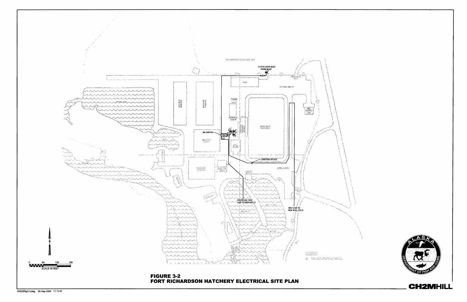
ML&P at a pole-top switch located near the Shop Storage Building. From the utility connection point, the feeder transitions belowground, and although the exact routing of the feeder may not be known at this time, the general configuration (Figure 3-2) is assumed to be accurate.
Belowground, the MV feeder runs west behind the Shop/Cold Storage Building and then turns south between the Operations Building and a raceway. On the north side of the Visitors Center are a generator module, three padmount transformers, a switch panel, and a 15-kV padmount distribution switch (PDS). Although not shown in sufficient detail in Figure 3-2, the MV feeder likely terminates at the PDS. From the PDS, the onsite loads are fed from the following feeders, which we have labeled F-1, F-2 and F-3:
• F-1 feeds power to the three padmount transformers located north of the Visitors Center. These transformers appear to power the Operations Building, Visitors Center, Incubation Building, Broodstock Building, and the new Water Treatment Building. The three transformers step the voltage down from 15 kV (likely 12,470 volts) to 480 volts. Each of the buildings is probably fed from the switch panel.
• F-2 transitions south, west of the Visitors Center, feeding power to the Aeration Building, and then transitions overhead to feed the far-field wells.
• F-3 transitions south, west of the Visitors Center, and then turns east, where it is spliced to an old section of 15-kV cable located near the southwest edge of the cooling pond. From there, the old F-3 section transitions east from the splice point and then north along the cooling pond to feed power to a well near the northeast corner of the cooling pond. The feeder then proceeds south along the east side of the cooling pond to feed additional wells.
Internal examination of the MV electrical equipment was not performed at this time although this activity is recommended. In addition, a survey of the buried location of the MV feeder will need to be performed as part of the design process for site improvements. All underground feeder lines need replacement, many of the lines are more than 20 years old and are known to be deteriorating.
3.1.13.2 Electrical Distribution–Low Voltage As described above, each of the site facilities and wells is likely fed off of one of the three MV feeders though a distribution transformer. The facilities are likely powered from a 3-phase, 480-volt transformer while the wells receive power from a single-phase, 240-volt source.
A preliminary survey of each facility and the site revealed that many of the low-voltage (LV) systems were in very poor condition. Although code and safety violations were numerous, they are not specifically identified for correction. This should be completed when the hatchery upgrade alternative scope is identified. Typical examples of electrical issues are exposed electrical conductors, various grounding problems (mostly bonding and corrosion issues), unused openings in electrical boxes, clearance in front of electrical panels and motor control centers (MCCs), inadequate lighting levels, broken conduit and fittings, and the lack of required labeling.
Single-line diagrams are not available for LV onsite or facility distribution at this time.

ASSESSMENT OF EXISTING ANCHORAGE AREA HATCHERIES
3-12 DIVISION OF SPORT FISH HATCHERY EVALUATION–ANCHORAGE AREA HATCHERIES
3.1.13.3 General Process Control and Alarms Systems The Supervisory Control and Data Acquisition (SCADA) system appears to be fairly new. The SCADA system is an Allen-Bradley programmable logic controller (PLC)-based system with operator interface screens located throughout process facilities. These systems are networked so that alarm annunciation and some control may be performed from any operator interface screen contained inside the process facilities.
We recommend that ADF&G obtain the electronic drawing and programming files from the systems integrator(s) who originally performed this work. This will enable efficient integration with the existing control systems or use and modification of the existing equipment during the design process for hatchery upgrades.
3.1.13.4 Well Operation and Water Storage Level Control The current process for operation of multiple water wells and maintaining the necessary water flow and temperature control in the raceways is relatively primitive. Site personnel are currently challenged with monitoring water storage levels and water flows and operating various combinations of wells to meet the demands of the hatchery process. The control and efficient operation of this process should be studied for optimization.
3.2 Elmendorf Hatchery 3.2.1 Process Water Supply Water supply for the Elmendorf hatchery comes from the following sources:
• Raw surface water from Ship Creek from an intake structure
• Heated surface water from Ship Creek returned from the Elmendorf Air Force Base power plant
• Groundwater from two wells
At least 95 percent of the total hatchery water flow comes from surface water from Ship Creek. The hatchery uses from 4,000 to 7,500 gpm from Ship Creek, with variation due to seasonal flow variation the creek. Often by mid- to late March, virtually all Ship Creek water is diverted into the hatchery/power plant. The maximum yearly water use of 7,500 gpm occurs from April to June. Raw surface water from Ship Creek flows by gravity into the intake diversion channel, where it is coarse screened with a 4-inch bar rack. Additional filtering occurs inside the Intake Building (Figure 5-1).
Although the surface water from Ship Creek is treated using particulate screening and degassing (addition of oxygen and removal of carbon dioxide and nitrogen), the Elmendorf hatchery is not considered a disease-free facility because it uses raw Ship Creek water,
ASSESSMENT OF EXISTING ANCHORAGE AREA HATCHERIES
DIVISION OF SPORT FISH HATCHERY EVALUATION–ANCHORAGE AREA HATCHERIES 3-15
which presents the potential for fish pathogen transfer from wild fish to hatchery fish. This is in contrast to Fort Richardson hatchery, which uses only well water to prevent introduction of pathogens through the water supply.
The following wells are available for operation at the Elmendorf hatchery:
• Well #1 is 140 feet deep and consistently supplies 320 gpm of water at 3.8 to 4.4°C. Water from this well is used for egg incubation purposes and the filling of fish transport trucks and can also be used for production during March, when flow in Ship Creek is at its lowest point.
• Well #2 is 230 feet deep and supplies 60 gpm. This well is rarely used.
Prevention of upstream salmon migration, through the continued maintenance of the existing dam, is desirable to minimize introduction of pathogens into the hatchery intake. There have been serious discussions about removing the drop structure to allow for rehabilitation efforts upon Ship Creek. Removal of the dam would require an alternate hatchery water intake.
3.2.2 Power Plant Cooling Pond Cold water from Ship Creek is diverted into the Elmendorf power plant cooling pond. Water from this pond is pumped to the power plant and used to cool the steam turbines. Hot water is returned to the Intake Building and used for heating hatchery process water, heating the Intake Building, maintaining an ice-free intake, and keeping the cooling pond at a temperature above 5°C year round.
3.2.3 Intake Building The purpose of the Intake Building is to capture and screen influent water from Ship Creek and blend it with Ship Creek water that has been warmed by the Elmendorf power plant. Warm water is then sent to the Degassing Building. Ambient-temperature (cold) water can also be diverted to the broodstock raceways when these are in use. Sumps for cold and warm water are located below floor level, and screens, pumps, and the control system equipment is located at floor level. The Intake Building is a wood-frame structure on concrete foundation. Roof beams need to be more closely examined and possibly reinforced. There are structural problems that are evident.
This facility is heated by an overhead-mounted air handling unit that mixes outside air with return air for ventilation and heats the discharge air using a hot water coil. The heating water for the coil is drawn from the hot water sump under the building, which comes directly from the power plant hot-water discharge. Damper control is pneumatic. An electric reheat section appears to be installed downstream of the hot-water heating coil but is not in use. This unit is old but in fair condition.
The heated water from the Elmendorf power plant is essential for continued operation of this building. Operators report that up to 700 gpm of 22°C water is necessary to keep the intake from freezing during occasional ice jams. Warm water also heats the building and increases the temperature of the process water. If the warm water supply is discontinued, water intake must be modified or the water intake will freeze.
ASSESSMENT OF EXISTING ANCHORAGE AREA HATCHERIES
3-16 DIVISION OF SPORT FISH HATCHERY EVALUATION–ANCHORAGE AREA HATCHERIES
3.2.4 Broodstock Raceways The broodstock raceways are a pair of aluminum raceways located next to Ship Creek, downstream of the hatchery water inlet. These raceways are used to hold Chinook and Coho salmon for broodstock. Mature salmon arriving in June-September swim up a fish ladder into the raceways, where they are held by a V-trap until mid-July, when eggs are stripped. Eggs are incubated on site. Smolt are released through the fish ladder to ensure imprinting. Each raceway is 8 feet wide and 90 feet long, with 78 feet available for fish culture between the inlet and outlet screens. The raceways are 4 feet deep but are generally operated with 3-foot water depth. The raceways are supplied by approximately 2,000 gpm of ambient-temperature Ship Creek water diverted from the Intake Building. Discharge from the raceways flows directly to Ship Creek.
3.2.5 Generator Building The emergency generator enclosure is heated by a gas-fired, horizontal unit heater. The unit is manufactured by Modine, with an output capacity of 45,650 Btu/h. During generator operation, radiator cooling air is drawn from outside. A portion of this air, after being heated by the engine radiator, is discharged to the room to provide supplemental heat as required. All equipment is in good condition.
3.2.6 Office/Incubation Building The eggs are fertilized in a bucket, and then brought to Heath Trays in the Incubation Building. The Office/Incubation Building includes a lunchroom, offices, and the egg incubation system, which consists of 18 standard 16-tray Heath stack incubators. The top tray in each stack is not used because of mixing and turbulence, leaving 15 useable trays per stack, for a total of 270 useable trays for incubation. Pumps and a temperature mixing valve are used to blend cold well water (3.8 to 4.4°C) and warm process water (18 to 22°C) to maintain the desired hatching temperature of 7° to 12°C. This water is directed into vacuum degassing columns located above each stack of trays and then flows into an aluminum head trough and into the trays.
The office areas and garage bay are heated with a gas-fired, horizontal unit heater. The unit is manufactured by Modine, with an output capacity of 112,500 Btu/h. A small propeller exhaust fan is located in the garage bay/incubation area, with a discharge damper. A ceiling paddle fan is also present. The restroom includes a water closet, laundry tub, and shower. Domestic hot water is provided by an electric tank-type water heater. The water heater has a 40-gallon capacity, with two 4,500-watt elements. All equipment is in fair to good condition.
An inherent problem with this building is the incompatibility of having offices and incubation under the same roof. The addition of chemicals required for incubation is a safety concern in the adjacent office space. Also, there is a shortage of space for fish food storage. A warm, stable temperature is desired for food storage.
3.2.7 Degassing Building The primary purpose of the Degassing Building is to house vacuum degassing columns, which remove nitrogen gas from the process water to eliminate chronic gas bubble trauma in the fish. As part of this process, the water is aerated and filtered. Both hot water (20 to
ASSESSMENT OF EXISTING ANCHORAGE AREA HATCHERIES
DIVISION OF SPORT FISH HATCHERY EVALUATION–ANCHORAGE AREA HATCHERIES 3-17
21°C) from the power plant and blended warm water (7 to 14°C) from the Intake Building are sent to separate floor sumps in the Degassing Building. Vertical turbine pumps lift the warm water to a surge tank that feeds a custom-built inclined wedgewire screen filter with 0.063-inch slot size. Particles removed on this screen filter slide down to a trough at the base of the unit. Water passing though the screen filter collects in an aluminum head box that feeds eight vacuum degassing units located beneath the filter.
The vacuum degassers are aluminum columns, 9 to 11 feet tall and 30.6 inches in diameter. Vacuum is applied to each to increase gas stripping performance. A 1.5-hp regenerative blower supplies vacuum to all eight degassing columns. Each degassing tower can handle up to 1,200 gpm. The columns reduce total gas pressure to approximately 98 to 100 percent and increase dissolved oxygen to 100 percent of saturation. After degassing, the treated process water collects in a sump that provides head pressure for the raceways. The warm-water and hot-water supplies flow by gravity to the production raceways. The hot-water supply can be directed to different points within the raceways.
The Degassing Building is heated by a gas-fired, horizontal unit heater, manufactured by Modine, capacity unknown. Two outside air dampers are located on the east wall. Both are closed, and one is stuffed full of insulation. The unit heater is in good condition; the dampers appear inoperable.
3.2.8 Maintenance Shop The Shop Building is heated by a central hot-water boiler, with hydronic unit heaters and baseboard convectors in the heated areas. The boiler is a Weil McLain P-766, gas-fired, 202,000-Btu/h capacity, in fair but operational condition. Hydronic unit heaters in the garage bays are served by uninsulated copper supply and return piping. The unit heaters are old and in poor condition. The restroom includes a water closet, lavatory, washer/dryer, and laundry tub. All are operational. An upstairs storage room has a sink and is heated by hydronic baseboard, in fair condition.
3.2.9 Raceways The raceways are where the fish are raised to desired size before stocking. The fish are fed in the raceways, and uneaten fish food and fish feces are manually removed by sweeping. The hatchery uses 19 concrete and 2 aluminum raceways. The concrete raceways are 10 feet wide and 68 feet long. The raceways are normally operated with a water depth of 3 feet, but there is a deeper section (4.5 feet deep, 10 feet long) at the end of each raceway designed to reduce flow and collect solids. Although the raceways can be operated in single-pass configuration, they are currently operated in a serial first-pass, second-pass configuration. Effluent from the 10 first-pass raceways is pumped through open degassing columns to the head of the 9 second-pass raceways. The degassing columns aerate the water and remove carbon dioxide. Water from the second-pass raceways is then pumped through a second set of degassing columns to the aluminum raceways for third-pass use. Warm water supply from the Degassing Building is also available at the third-pass raceways. Reuse of water in this second-pass/third-pass manner is not optimal because it increases the possibility of introducing pathogens from first-pass raceways to fish in second- and third-pass raceways.
ASSESSMENT OF EXISTING ANCHORAGE AREA HATCHERIES
3-18 DIVISION OF SPORT FISH HATCHERY EVALUATION–ANCHORAGE AREA HATCHERIES
The maximum flow that can be applied to the second-pass raceways is 5,500 gpm. Due to this flow limitation, normal water velocity in the second-pass raceways is only 1.25 cm/s, which means that solids (uneaten fish food and fish feces) settle out in the raceways and have to be swept and flushed weekly. The solids are swept to a floor drain at the deep end of each raceway, then gravity flow to the settling pond. A waterproof coating and an epoxy seal coat have been applied to the concrete raceways to repair and minimize pitting and cracking. This has apparently worked well.
One problem inherent in the use of outdoor raceways is keeping disease vectors (birds and mammals) away from the fish. Enclosing these raceways with a building would greatly improve the working conditions for hatchery personnel in the winter months and provide for secure biocontrol.
3.2.10 Summary of Existing Electrical Systems 3.2.10.1 Electrical Distribution Electrical power for the Elmendorf hatchery is provided by ML&P. The 600-amp ML&P service for the hatchery connects at the Generator Building and is distributed to the various site facilities from the main distribution panel at 480 volts alternating current (VAC). The Generator Building also contains a 225-kW standby generator and an automatic transfer switch. The hatchery self-generates electrical power anytime the utility source becomes either unavailable or unstable.
A preliminary survey of each facility and the site revealed that many of the LV systems were in very poor condition and would need attention if the hatchery continues to operate as a visitor center and broodstock/release area.
3.2.10.2 General Process Control and Alarms Systems The SCADA system appears to be antiquated. The systems are not integrated into a common alarm system, and adequate monitoring from a single location is not possible with the installed equipment.
Onsite personnel desire replacement of the existing alarm and monitoring systems in the Intake and Sump Buildings with visibility of all systems from the Office Building.
3.2.10.3 Electrical Recommendations The following work is recommended if the Elmendorf hatchery will continue operation for more than a few years:
• Survey existing configuration of site and facility LV distribution systems and inspection of LV equipment. The existing systems should be documented with necessary repairs only to the extent that those systems will be reused or rebuilt. Systems to be retired or abandoned in place should be documented for removal.
• Design and install improved interior (existing building areas) and exterior (perimeter and parking lot) lighting systems.
• Design and install new hatchery control, alarm, and monitoring system. Integrate with existing local controls that are operational and in good physical condition. Damaged

ASSESSMENT OF EXISTING ANCHORAGE AREA HATCHERIES
DIVISION OF SPORT FISH HATCHERY EVALUATION–ANCHORAGE AREA HATCHERIES 3-19
local control systems should be replaced entirely. Network controls system for installation of operator interface screen for central alarming and monitoring inside the Office Building.
3.3 Existing Facilities Capability to Meet Current and Future Production Goals As summarized in Section 1, the Fort Richardson and Elmendorf hatcheries have been producing all of the hatchery fish for Region II (Southcentral Alaska) and Region III (Interior Alaska), enabling the ADF&G Sport Fish Division to accomplish their mission of reducing pressure on wild fish stocks and opening new fisheries where none previously existed. If funding becomes available, the new hatchery planned for Region III in Fairbanks will produce hatchery fish for that region and reduce some of the current production requirements for the Anchorage-area hatcheries. However, there is a significant increase in the projected demand and therefore in production goals for Region II in the coming years (Table 2-1). Based on the deteriorating conditions of the existing hatchery facilities, the loss of free waste heat from the Fort Richardson and Elmendorf power plants, and the uncertainty of the volume of high-quality well water that will continue to be available at the Fort Richardson hatchery, the design and construction of a new recirculation facility is recommended as the best way to maintain and expand the hatchery production for Region II. Such a facility will require significantly less water volume and therefore less heat than a conventional flow-through facility. There is every expectation that a new facility will be able to safely and reliably meet the production goals established by ADF&G within the given resource and funding constraints. Two alternative plans are presented in Section 4: (1) a new recirculation facility that can meet future production goals, and (2) minimal repairs and upgrades to the existing hatcheries to meet current production goals.
The continued success of the Anchorage-area hatchery program located at the existing Fort Richardson site is dependent upon the following key issues:
• Continued support of hatchery operations by the U.S. Army, with guaranteed assurance that the land occupied by the hatchery will be available for long-term operations
• Availability from the existing well fields of a minimum of 1,500 gpm of high-quality water for the long-term operation of the hatchery (Alternative I) or availability of 3,500 gpm of high-quality water for the long-term hatchery (Alternative II)
If the above conditions cannot be satisfied, then design and construction of either Alternative I or Alternative II at this site may not be the best way to ensure maintenance of Region II fish production.
3.3.1 Schedule The U.S. Air Force plans to close the Elmendorf power plant in October of 2005. At that point there will not be waste heat available for the Elmendorf hatchery to continue the production of catchable Rainbow trout and landlocked Chinook salmon. Neither of the alternatives presented in this report could be implemented before spring of 2008. Therefore,

ASSESSMENT OF EXISTING ANCHORAGE AREA HATCHERIES
3-20 DIVISION OF SPORT FISH HATCHERY EVALUATION–ANCHORAGE AREA HATCHERIES
a final plan forward must be implemented as soon as possible to minimize the near term loss of catchable production.
Recommended