
THE DESIGN AND IMPLEMENTATION OF HUMAN RESOURCE
MANAGEMENT WEBSITE
By
Soumya R Lingareddy
Project Report Submitted to the faculty of the
University Graduate School
in partial fulfillment of the requirements
for the degree
Master of Science
in the
Department of Computer and Information Sciences
Indiana University South Bend
May 2007
Committee Members:
Dr. Hossein Hakimzadeh, Advisor
Dr. Dana Vrajitoru
Dr. Liguo Yu

ii
Accepted by the Master Thesis Committee, Indiana University South Bend, in partial fulfillment of the requirements for the degree of Master of Science in Applied Mathematics and Computer Science.
Master Thesis Committee _________________________________
Chairperson, Dr. Hossein Hakimzadeh
_________________________________
Dr. Dana Vrajitoru
_________________________________
Dr. Liguo Yu
Date of Oral Examination:
Monday, May 14, 2007
_________________________________
Dr. Hossein Hakimzadeh

iii
©2007
Soumya Lingareddy
All Rights Reserved

iv
ACKNOWLEDGMENTS
In completing this graduate project I have been fortunate to have help, support
and encouragement from many people. I would like to acknowledge them for their
cooperation.
First, I would like to thank Dr. Hossein Hakimzadeh, my project advisor, for
guiding me through each and every step of the process with knowledge and support.
Thank you for your advice, guidance and assistance.
I would also like to thank Dr. Vrajitoru and Dr. Yu, my project committee
members, who showed immense patience and understanding throughout the project and
provided suggestions.
Finally, I would like to thank my husband Mahesh, my parents Mohan and
Savithri, my sister Deepya, and my friend Swapna for their love, encouragement and help
throughout the project.
v
ABSTRACT
The consulting industry is one of the fastest growing business sectors worldwide
with new opportunities emerging continually in hundreds of different fields. Software
consulting and recruiting agencies match the requirements of the client firms with the
skills of their employees and set up the interview between their employees and the client
firm. Interviews are then conducted, and the candidates selected in the interview are
recruited as consultants or contractors in the client’s firm for the duration of the project
(job).
This project examines the issues related to dynamic Human Resource
Management and implements a web-based application for a fictitious consulting firm that
participates in the placement of contractors in different organizations. The system is
implemented using a 3-tier approach, with a backend database (MySQL database), a
middle tier of Microsoft Internet Information Services (IIS) and ASP.NET, and a front
end web browser (client). This report also discusses each of the underlying technologies
used to create and implement the application
vi
TABLE OF CONTENTS
1. INTRODUCTION......................................................................................................... 1
2. LITERATURE REVIEW ............................................................................................ 2
3. DESIGN OF THE PROJECT...................................................................................... 4
3.1. DATA MODEL....................................................................................................... 4 3.1.1 Database Design................................................................................................ 7
3.2. PROCESS MODEL ............................................................................................. 10 3.2.1. Functional Decomposition Diagram............................................................. 10 3.2.2. Data Flow Diagram ....................................................................................... 12
3.3. USER INTERFACE DESIGN............................................................................. 28
4. PROPOSED SYSTEM ............................................................................................... 31
5. IMPLEMENTATION TECHNOLOGIES............................................................... 33
5.1. IIS .......................................................................................................................... 34 5.1.1 Static Web pages.............................................................................................. 34 5.1.2. Dynamic Web Pages....................................................................................... 36
5.1.2.1. Client-Side Dynamic Web Page ................................................................. 36 5.1.2.2. Server-Side Dynamic Web Page................................................................. 38
5.2. ASP.NET ............................................................................................................... 40 5.3. MYSQL.................................................................................................................. 42
6. CONNECTING TO THE DATABASE .................................................................... 44
6.1. ADO.NET.............................................................................................................. 44 6.1.1. Connecting the Application to MySQL using ADO.NET............................. 47
7. APPLICATION........................................................................................................... 49
7.1. EMPLOYEE APPLICANT ......................................................................................... 50 7.2. EMPLOYER CONTACT............................................................................................ 53 7.3. ADMINISTRATOR.................................................................................................... 58
8. LIMITATIONS AND FUTURE DEVELOPMENT................................................ 70
9. CONCLUSION ........................................................................................................... 70
10. REFERENCES.......................................................................................................... 72
11. BIBLIOGRAPHY..................................................................................................... 74
vii
TABLE OF FIGURES
FIGURE 1 ENTITY-RELATION DIAGRAM............................................................................... 6 FIGURE 2 FUNCTIONAL DECOMPOSITION DIAGRAM........................................................... 11 FIGURE 3 EXAMPLE OF A DATA FLOW DIAGRAM............................................................... 12 FIGURE 4 USER AUTHENTICATION DFD ............................................................................ 13 FIGURE 5 EMPLOYEE APPLICANT - UPDATE PROFILE CONTEXT DFD................................ 14 FIGURE 6 EMPLOYEE APPLICANT - UPDATE PROFILE DETAILED DFD............................... 14 FIGURE 7 EMPLOYEE APPLICANT - VIEW INTERVIEW SCHEDULE DFD.............................. 15 FIGURE 8 ADMINISTRATOR - UPDATE DFD ....................................................................... 16 FIGURE 9 ADMINISTRATOR – CREATE NEW USER PROFILE CONTEXT DFD....................... 16 FIGURE 10 ADMINISTRATOR – CREATE NEW USER PROFILE DETAILED DFD.................... 17 FIGURE 11 ADMINISTRATOR - TERMINATE USER LOGIN DFD........................................... 18 FIGURE 12 ADMINISTRATOR - INTERVIEW SCHEDULE CONTEXT DFD............................... 18 FIGURE 13 ADMINISTRATOR - INTERVIEW SCHEDULE DETAILED DFD.............................. 19 FIGURE 14 ADMINISTRATOR - ADD INTERVIEW DETAIL DFD............................................ 20 FIGURE 15 ADMINISTRATOR - MAINTAIN JOB CONTRACT CONTEXT DFD......................... 21 FIGURE 16 ADMINISTRATOR - MAINTAIN JOB CONTRACT DETAILED DFD........................ 22 FIGURE 17 ADMINISTRATOR - VIEW JOB ORDER DFD....................................................... 23 FIGURE 18 ADMINISTRATOR - VIEW EVALUATION DFD.................................................... 23 FIGURE 19 EMPLOYER CONTACT - UPDATE CONTEXT DFD .............................................. 24 FIGURE 20 EMPLOYER CONTACT - UPDATE DETAILED DFD ............................................. 25 FIGURE 21 EMPLOYER CONTACT - JOB ORDER CONTEXT DFD ......................................... 26 FIGURE 22 EMPLOYER CONTACT - JOB ORDER DETAILED DFD ........................................ 26 FIGURE 23 EMPLOYER CONTACT - ADD EVALUATION DFD .............................................. 27 FIGURE 24 EMPLOYER CONTACT - EMPLOYEE APPLICANTS EVALUATION ........................ 27 FIGURE 25 EMPLOYER CONTACT - VIEW INTERVIEW SCHEDULE....................................... 28 FIGURE 26 LOGIN FORM..................................................................................................... 28 FIGURE 27 EMPLOYEE APPLICANT REGISTRATION FORM .................................................. 29 FIGURE 28 EMPLOYER CONTACT REGISTRATION FORM..................................................... 29 FIGURE 29 JOB ORDER ENTRY FORM ................................................................................. 30 FIGURE 30 JOB CONTRACT FORM....................................................................................... 30 FIGURE 31 THREE-TIER ARCHITECTURE ............................................................................. 31 FIGURE 32 COMMUNICATION BETWEEN CLIENT AND WEB-SERVER.................................... 33 FIGURE 33 STEPS FOR CREATING A STATIC WEB PAGE [8]................................................. 35 FIGURE 34 STEPS FOR CREATING A CLIENT SIDE DYNAMIC WEB PAGE [8]......................... 37 FIGURE 35 STEPS FOR CREATING SERVER SIDE DYNAMIC WEB PAGE ................................ 39 FIGURE 36 ASP.NET ARCHITECTURE WITH IIS 5.0 [10] .................................................... 41 FIGURE 37 ADO.NET ARCHITECTURE ............................................................................... 45 FIGURE 38 LOGIN PAGE ..................................................................................................... 49 FIGURE 39 APPLICANT - MENU .......................................................................................... 50 FIGURE 40 APPLICANT - UPDATE PERSONAL INFORMATION .............................................. 51 FIGURE 41 APPLICANT - UPDATE SKILL INFORMATION...................................................... 51 FIGURE 42 APPLICANT - UPDATE RESUME......................................................................... 52 FIGURE 43 APPLICANT – VIEW INTERVIEW SCHEDULE ...................................................... 52 FIGURE 44 CONTACT - MENU............................................................................................. 53
viii
FIGURE 45 CONTACT - UPDATE PERSONAL INFORMATION................................................. 54 FIGURE 46 CONTACT - UPDATE COMPANY INFORMATION ................................................. 54 FIGURE 47 CONTACT - ADD NEW JOB ORDER.................................................................... 55 FIGURE 48 CONTACT - UPDATE JOB ORDER....................................................................... 56 FIGURE 49 CONTACT - VIEW INTERVIEW SCHEDULE ......................................................... 57 FIGURE 50 CONTACT - ADD NEW EVALUATION................................................................. 57 FIGURE 51 ADMINISTRATOR – MENU................................................................................. 58 FIGURE 52 ADMINISTRATOR - UPDATE PERSONAL INFORMATION ..................................... 59 FIGURE 53 ADMINISTRATOR - ADD NEW APPLICANT ........................................................ 60 FIGURE 54 ADMINISTRATOR - ADD NEW ADMINISTRATOR................................................ 61 FIGURE 55 ADMINISTRATOR - ADD NEW CONTACT ........................................................... 62 FIGURE 56 ADMINISTRATOR - ADD NEW CLIENT............................................................... 63 FIGURE 57 ADMINISTRATOR - TERMINATE USER LOGIN .................................................... 63 FIGURE 58 ADMINISTRATOR - ADD NEW INTERVIEW SCHEDULE....................................... 64 FIGURE 59 ADMINISTRATOR - UPDATE INTERVIEW SCHEDULE.......................................... 65 FIGURE 60 ADMINISTRATOR - ADD INTERVIEW DETAILS ................................................... 66 FIGURE 61 ADMINISTRATOR - ADD JOB CONTRACT ........................................................... 67 FIGURE 62 ADMINISTRATOR - UPDATE JOB CONTRACT ..................................................... 68 FIGURE 63 ADMINISTRATOR - TERMINATE JOB CONTRACT ............................................... 69
1
1. INTRODUCTION
Software consulting and recruiting agencies match the requirements of the client
firms with the skills of their employees and set up the interview between their employees
and the client firm. Interviews are then conducted, and the candidates selected in the
interview are recruited as consultants in the client’s firm for the duration of the project.
The recent downsizing in businesses and other organizations has resulted in an
increase in consulting business for two reasons. Many experienced and well-qualified
professionals have found that offering their services on a consulting basis meets both
their career and financial needs. Secondly, after downsizing, organizations find it
economical and flexible to use consultants rather than full-time employees to fill their
fluctuating technical, management and operation needs.
The above factors have led to the consulting industry becoming one of the fastest
growing business sectors worldwide. Hence the consulting firms are attempting to
automate as much routine activities as possible. An effective web-application can be a
proper medium for bringing all the above parties together.
Web-based applications are web sites with user interactivity. The key advantage
of the web-based application is its availability, as it can be accessed by anyone connected
to the Internet and multiple users can access it at the same time. The web-application can
be designed as a three-tier architecture, which includes a web client, network servers, and
a back-end information system supported by a suite of databases [2]. The goal of this
project is to develop a user- friendly web-based application that automates the routine
activities for an IT consulting firm.
2
2. LITERATURE REVIEW
It is important to realize that many organizations are no longer staffed entirely by
full time permanent employees. Activities previously done within firms are now
accomplished externally by other businesses that specialize in those functions. The above
factor has created rapid growth in many business sectors including computer and data
processing services.
Large organizations frequently have a mixture of permanent employees and
staffing based on Alternative Employment Structures (AES). The most significant
categories of AES are outsourcing and consulting [1]. “Nearly four out of five employers
use some form of nontraditional staffing arrangement” [5]. The non-traditional
workforce, defined by U.S. Department of Labor, Bureau of Labor Statistics (BLS)
includes multiple jobholders, contingent and part-time workers, people in alternate work
arrangements, independent contractors/consultants and employees of contract companies.
According to the Bureau of Labor Statistics (BLS) the non-traditional workforce is
expected to grow by almost 50 percent from 2000 to 2010, compared to a 15 percent
increase in permanent workers during the same time [3].
The computer industry and its related services are expected to experience rapid
growth, adding 453,000 jobs between 2004 and 2014 [7]. As computers and software
become more complex, support specialists will be needed to provide technical assistance
to customers and other users. This in turn will increase the demand for consultants in the
area of computers and software management.
As more companies seek to meet their technical needs by employing consultants,
there is a growing demand for software tools, which will aid in dealing with the
complexities of this new human resource management model. Over the past few years
many vendors have created different software solutions for recruiting. Some of the
available software solutions include, cBizOne [12], Attract Recruiter [13] and
PCRecruiter [14].
3
Most of these solutions provide features such as,
• Employee database with the advanced search option
• Company database with the advanced search option
• Job search capability
• Interview scheduling
• contracts management
• performance reports
These solutions can also be customized wherein any of the above mentioned
features can be selected to suit the recruiting company’s business needs. A package that
includes a minimum set of features could cost approximately $1000 per user. A small-
size consulting firm has a minimum of 5 to 10 administrators who need to be registered
users for the application products, in order to perform different tasks needed for their
consulting firm. Additional features such as automated e-mail notification and calendar
updates can be added for an additional price, which makes this an increasingly expensive
product to purchase.
This project implements features such as employee database, company
management, interview planning and scheduling, job vacancies and contract management
and performance review reports, that are required to perform most of the operations in an
IT consulting firm.
4
3. DESIGN OF THE PROJECT
A consulting firm has three kinds of users that access the system, the Employee
Applicant, the Employer Contact and the Administrator. Employee Applicants are those
who apply for the jobs through the consultancy. The Applicant can update the existing
details in the Applicant’s database including their personal information, skills and
resume. Client is the company that seeks the services of the employees of a consulting
firm. A client firm may have many employees, Employer Contacts, which require
access to the system in order to add or update job or company information. The
Administrator matches the skills of its employee with the skills required by the client
company for a particular job and arranges an interview between the client contact and the
Applicant. After a successful interview process, the Administrator will facilitate the
consummation of the contract between the employee and employer.
To design the application, the relational database must be designed first. The data
model and the process model are part of the design process. The data model focuses on
how the database is structured while the process model deals with how the data is
processed. In the context of the relational database, the data model is used to design the
relational tables and the process model is used to design the queries that access and
perform operations on those tables.
3.1. DATA MODEL
Data modeling is performed during the initial phases of the database development
process. The data model focuses mainly on what information should be stored in the
database. The information needed to build the data model is gathered during the
requirement analysis. A comprehensive data model should take into account the current
and future needs of an organization in order to support the business process within an
organization.
5
To develop an effective web-based application for Human Resource Management,
a consulting firm must maintain accurate and up to date information about companies and
their prospective jobs as well as potential employees, including their skills and
availability for employment.
In order to accommodate the above requirement s a data model must be designed
that captures the essential entities and relationship that are present in a Human Resource
Management application. An Entity Relationship Diagram (ERD) gives a graphical
representation of the tables (entities) in the database and the relation between them.
The entities are represented by a “rectangle”, while a “diamond” represents the
relation between them and a diamond within a rectangle represents an associate entity.
The cardinality is the frequency of a relationship between two entities. The types of
cardinality are
• one to one (1:1), every record in entity A matches exactly one record in entity B
and every record in B matches exactly one record in A,
• one to many (1: M), every record in A matches zero or more records in B and
every record in B matches exactly one record in A, and
• many to many (M: M), every record in A matches zero or more records in B and
every record in B matches zero or more records in A.
If there is a many to many relationship between two entities, then the relationship
between them is represented as Associative Entities. Figure 1 shows the data model for
this application.
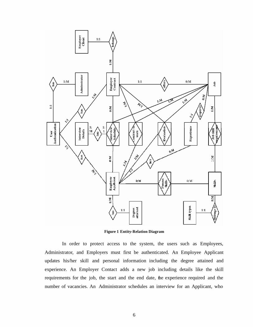
6
Figure 1 Entity-Relation Diagram
In order to protect access to the system, the users such as Employees,
Administrator, and Employers must first be authenticated. An Employee Applicant
updates his/her skill and personal information including the degree attained and
experience. An Employer Contact adds a new job including details like the skill
requirements for the job, the start and the end date, the experience required and the
number of vacancies. An Administrator schedules an interview for an Applicant, who
7
possesses the skills required for the job. Upon a successful interview, the Applicant and
the Contact enter into a contract for the job. After completion of the job, Employee
Applicant is evaluated on his/her performance.
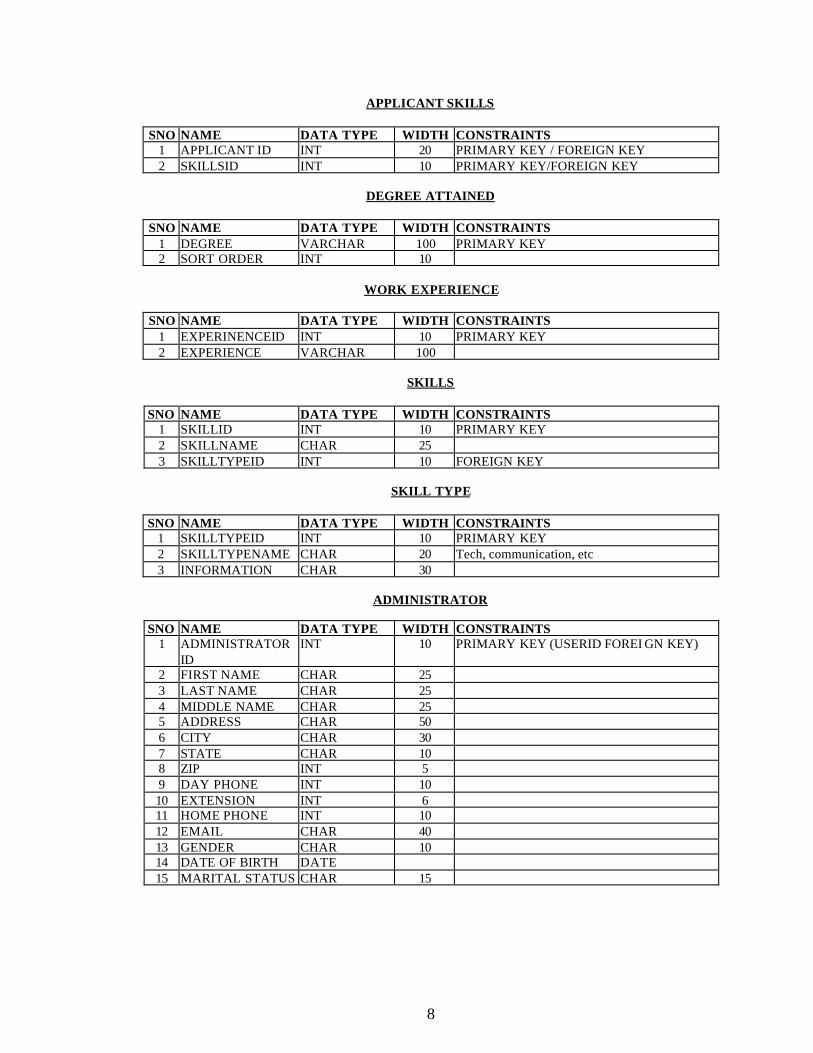
3.1.1 Database Design
In the Relational Database model, each of the entities including the Associate
entities is transformed into a table. The attributes (fields) of each of the entities for the
ERD shown in Figure 1 are as follows.
USER AUTHENTICATION
SNO NAME DATA TYPE WIDTH CONSTRAINTS
1 USERID INT 10 PRIMARY KEY 2 USERNAME CHAR 20 3 PASSWORD CHAR 20 4 ROLE CHAR 20 Applicant, client or administrator 5 ACTIVE YES/NO user has an active login
The “role” in the above table describes the relationship of the user with the firm, whether the user is an applicant or a client or the administrator in the firm.
EMPLOYEE APPLICANT SNO NAME DATA TYPE WIDTH CONSTRAINTS
1 APPLICANT ID INT 10 PRIMARY KEY (USERID FOREIGN KEY) 2 FIRST NAME CHAR 25 3 LAST NAME CHAR 25 4 MIDDLE NAME CHAR 25 5 ADDRESS CHAR 50 6 CITY CHAR 50 7 STATE CHAR 10 8 ZIP INT 5 9 DAY PHONE INT 10 10 EXTENSION INT 6 11 HOME PHONE INT 10 12 EMAIL CHAR 40 13 GENDER CHAR 10 14 DATE OF BIRTH DATE 15 MARITAL STATUS CHAR 15 16 DEGREE
ATTAINED CHAR 25 FOREIGN KEY
17 EXPERIENCE INTEGER FOREIGN KEY 18 RESUMESIZE INTEGER File size of the resume 19 RESUME Doc file
8
APPLICANT SKILLS SNO NAME DATA TYPE WIDTH CONSTRAINTS
1 APPLICANT ID INT 20 PRIMARY KEY / FOREIGN KEY 2 SKILLSID INT 10 PRIMARY KEY/FOREIGN KEY
DEGREE ATTAINED
SNO NAME DATA TYPE WIDTH CONSTRAINTS
1 DEGREE VARCHAR 100 PRIMARY KEY 2 SORT ORDER INT 10
WORK EXPERIENCE
SNO NAME DATA TYPE WIDTH CONSTRAINTS
1 EXPERINENCEID INT 10 PRIMARY KEY 2 EXPERIENCE VARCHAR 100
SKILLS
SNO NAME DATA TYPE WIDTH CONSTRAINTS
1 SKILLID INT 10 PRIMARY KEY 2 SKILLNAME CHAR 25 3 SKILLTYPEID INT 10 FOREIGN KEY
SKILL TYPE
SNO NAME DATA TYPE WIDTH CONSTRAINTS
1 SKILLTYPEID INT 10 PRIMARY KEY 2 SKILLTYPENAME CHAR 20 Tech, communication, etc 3 INFORMATION CHAR 30
ADMINISTRATOR
SNO NAME DATA TYPE WIDTH CONSTRAINTS
1 ADMINISTRATOR ID
INT 10 PRIMARY KEY (USERID FOREI GN KEY)
2 FIRST NAME CHAR 25 3 LAST NAME CHAR 25 4 MIDDLE NAME CHAR 25 5 ADDRESS CHAR 50 6 CITY CHAR 30 7 STATE CHAR 10 8 ZIP INT 5 9 DAY PHONE INT 10 10 EXTENSION INT 6 11 HOME PHONE INT 10 12 EMAIL CHAR 40 13 GENDER CHAR 10 14 DATE OF BIRTH DATE 15 MARITAL STATUS CHAR 15
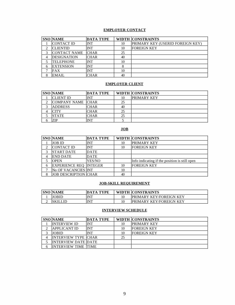
9
EMPLOYER CONTACT SNO NAME DATA TYPE WIDTH CONSTRAINTS
1 CONTACT ID INT 10 PRIMARY KEY (USERID FOREIGN KEY) 2 CLIENTID INT 10 FOREIGN KEY 3 CONTACT NAME CHAR 25 4 DESIGNATION CHAR 40 5 TELEPHONE INT 10 6 EXTENSION INT 8 7 FAX INT 10 8 EMAIL CHAR 40
EMPLOYER CLIENT
SNO NAME DATA TYPE WIDTH CONSTRAINTS
1 CLIENT ID INT 10 PRIMARY KEY 2 COMPANY NAME CHAR 25 3 ADDRESS CHAR 40 4 CITY CHAR 25 5 STATE CHAR 25 6 ZIP INT 5
JOB
SNO NAME DATA TYPE WIDTH CONSTRAINTS
1 JOB ID INT 10 PRIMARY KEY 2 CONTACT ID INT 10 FOREIGN KEY 3 START DATE DATE 4 END DATE DATE 5 OPEN YES/NO Info indicating if the position is still open 6 EXPERIENCE REQ INTEGER 10 FOREIGN KEY 7 No OF VACANCIES INT 10 8 JOB DESCRIPTION CHAR 40
JOB-SKILL REQUIREMENT
SNO NAME DATA TYPE WIDTH CONSTRAINTS
1 JOBID INT 10 PRIMARY KEY/FOREIGN KEY 2 SKILLID INT 10 PRIMARY KEY/FOREIGN KEY
INTERVIEW SCHEDULE
SNO NAME DATA TYPE WIDTH CONSTRAINTS
1 INTERVIEW ID INT 10 PRIMARY KEY 2 APPLICANT ID INT 10 FOREIGN KEY 3 JOBID INT 10 FOREIGN KEY 4 INTERVIEW TYPE CHAR 25 5 INTERVIEW DATE DATE 6 INTERVIEW TIME TIME
10
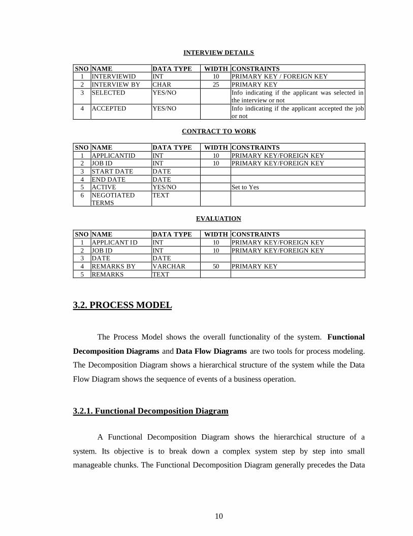
INTERVIEW DETAILS
SNO NAME DATA TYPE WIDTH CONSTRAINTS 1 INTERVIEWID INT 10 PRIMARY KEY / FOREIGN KEY 2 INTERVIEW BY CHAR 25 PRIMARY KEY 3 SELECTED YES/NO Info indicating if the applicant was selected in
the interview or not 4 ACCEPTED YES/NO Info indicating if the applicant accepted the job
or not
CONTRACT TO WORK SNO NAME DATA TYPE WIDTH CONSTRAINTS
1 APPLICANTID INT 10 PRIMARY KEY/FOREIGN KEY 2 JOB ID INT 10 PRIMARY KEY/FOREIGN KEY 3 START DATE DATE 4 END DATE DATE 5 ACTIVE YES/NO Set to Yes 6 NEGOTIATED
TERMS TEXT
EVALUATION
SNO NAME DATA TYPE WIDTH CONSTRAINTS
1 APPLICANT ID INT 10 PRIMARY KEY/FOREIGN KEY 2 JOB ID INT 10 PRIMARY KEY/FOREIGN KEY 3 DATE DATE 4 REMARKS BY VARCHAR 50 PRIMARY KEY 5 REMARKS TEXT
3.2. PROCESS MODEL
The Process Model shows the overall functionality of the system. Functional
Decomposition Diagrams and Data Flow Diagrams are two tools for process modeling.
The Decomposition Diagram shows a hierarchical structure of the system while the Data
Flow Diagram shows the sequence of events of a business operation.
3.2.1. Functional Decomposition Diagram
A Functional Decomposition Diagram shows the hierarchical structure of a
system. Its objective is to break down a complex system step by step into small
manageable chunks. The Functional Decomposition Diagram generally precedes the Data
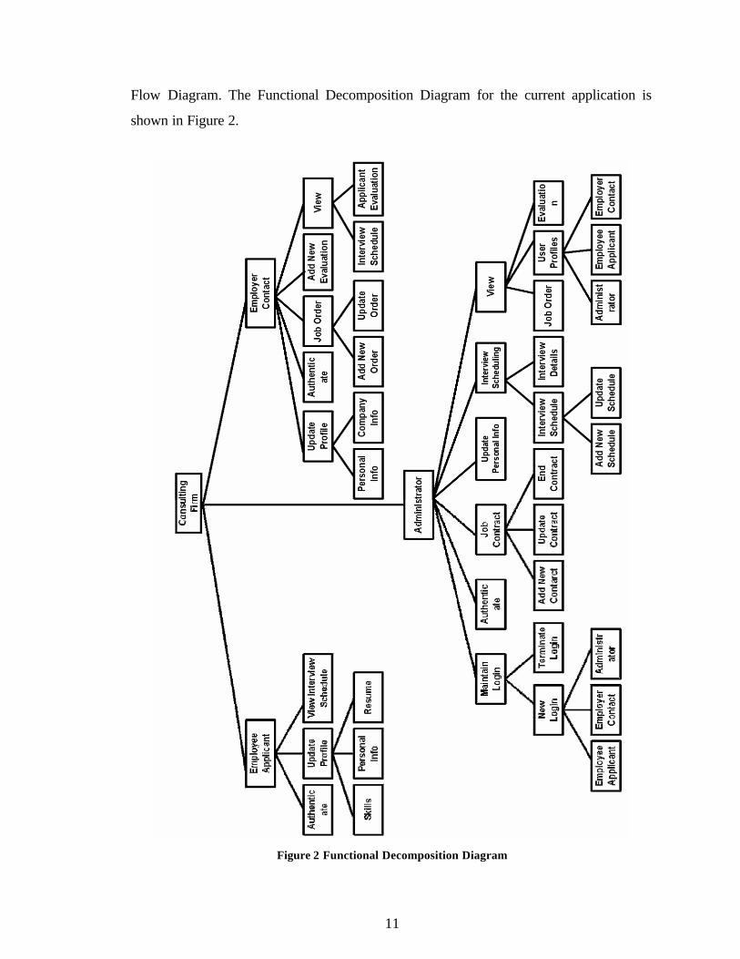
11
Flow Diagram. The Functional Decomposition Diagram for the current application is
shown in Figure 2.
Figure 2 Functional Decomposition Diagram
12
The application can be divided into three sub systems, Employee Applicant,
Administrator and Employer Contact. The Employee Applicant can authenticate, update
his/her profile and view his/her interview schedule. The Administrator can authenticate,
update personal information, maintain user’s login and view user profile, job order or
evaluation. Administrator can also add or update interview schedules, add interview
details and add, update or end job contracts. The Employer Contact can authenticate,
update personal or company information, add or update job orders and add evaluations.
The Employer Contact can also view interview schedules and evaluation of an Applicant
added by all the Contacts of the company.
3.2.2. Data Flow Diagram
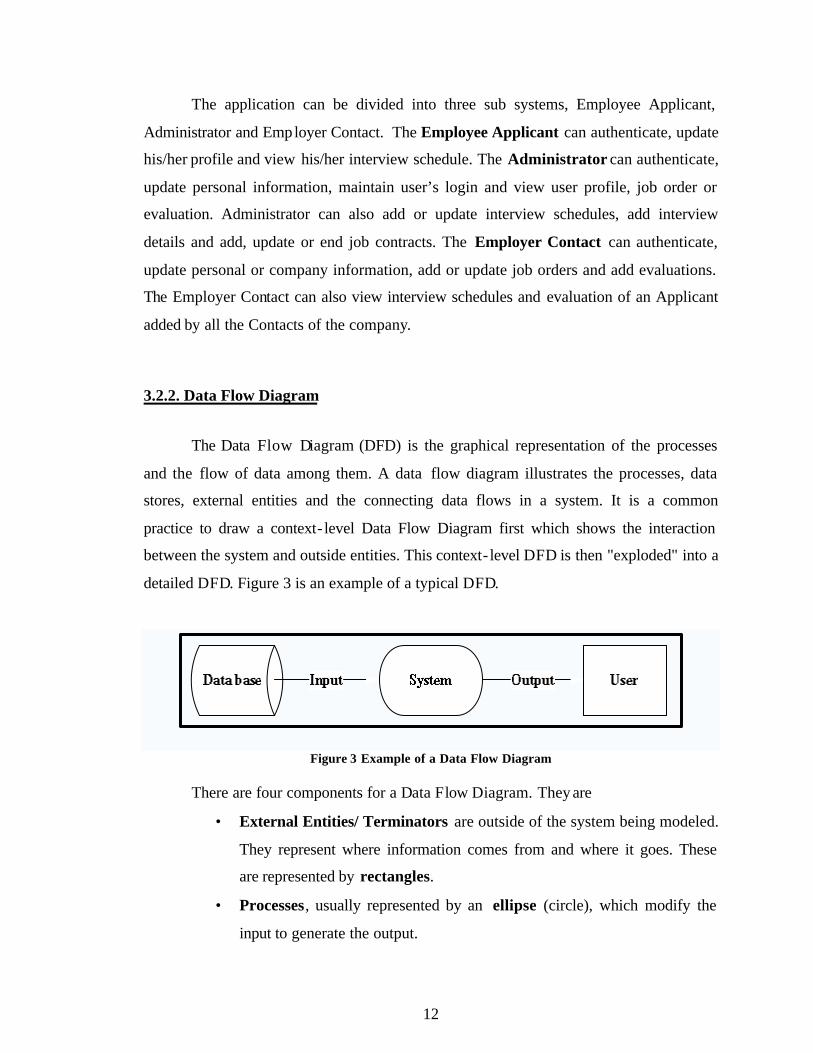
The Data Flow Diagram (DFD) is the graphical representation of the processes
and the flow of data among them. A data flow diagram illustrates the processes, data
stores, external entities and the connecting data flows in a system. It is a common
practice to draw a context- level Data Flow Diagram first which shows the interaction
between the system and outside entities. This context- level DFD is then "exploded" into a
detailed DFD. Figure 3 is an example of a typical DFD.
Figure 3 Example of a Data Flow Diagram
There are four components for a Data Flow Diagram. They are
• External Entities/ Terminators are outside of the system being modeled.
They represent where information comes from and where it goes. These
are represented by rectangles.
• Processes, usually represented by an ellipse (circle), which modify the
input to generate the output.
13
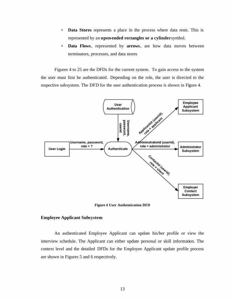
• Data Stores represents a place in the process where data rests. This is
represented by an open-ended rectangles or a cylinder symbol.
• Data Flows , represented by arrows , are how data moves between
terminators, processes, and data stores
Figures 4 to 25 are the DFDs for the current system. To gain access to the system
the user must first be authenticated. Depending on the role, the user is directed to the
respective subsystem. The DFD for the user authentication process is shown in Figure 4.
Figure 4 User Authentication DFD
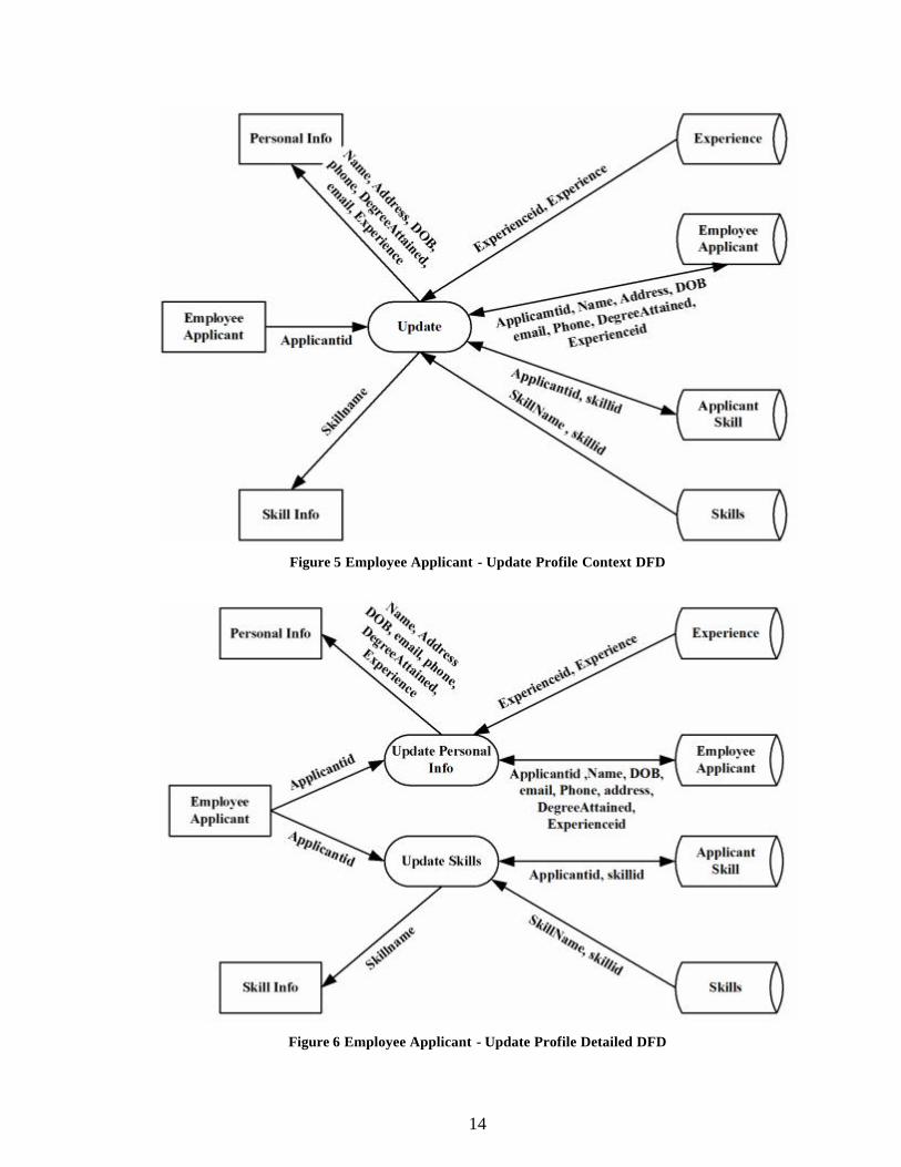
Employee Applicant Subsystem
An authenticated Employee Applicant can update his/her profile or view the
interview schedule. The Applicant can either update personal or skill information. The
context level and the detailed DFDs for the Employee Applicant update profile process
are shown in Figures 5 and 6 respectively.
14
Figure 5 Employee Applicant - Update Profile Context DFD
Figure 6 Employee Applicant - Update Profile Detailed DFD
15
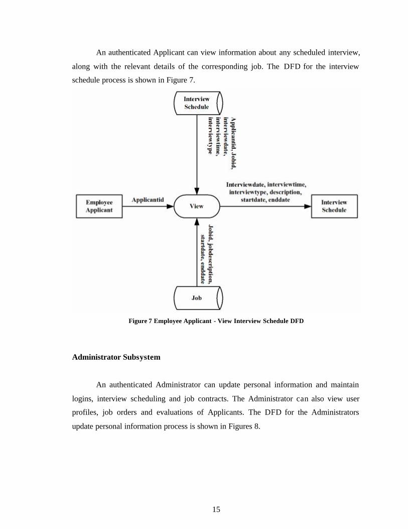
An authenticated Applicant can view information about any scheduled interview,
along with the relevant details of the corresponding job. The DFD for the interview
schedule process is shown in Figure 7.
Figure 7 Employee Applicant - View Interview Schedule DFD
Administrator Subsystem
An authenticated Administrator can update personal information and maintain
logins, interview scheduling and job contracts. The Administrator can also view user
profiles, job orders and evaluations of Applicants. The DFD for the Administrators
update personal information process is shown in Figures 8.
16
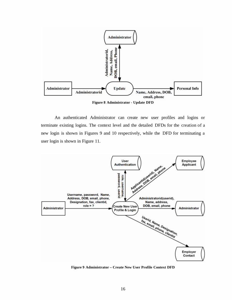
Figure 8 Administrator - Update DFD
An authenticated Administrator can create new user profiles and logins or
terminate existing logins. The context level and the detailed DFDs for the creation of a
new login is shown in Figures 9 and 10 respectively, while the DFD for terminating a
user login is shown in Figure 11.
Figure 9 Administrator – Create New User Profile Context DFD
17
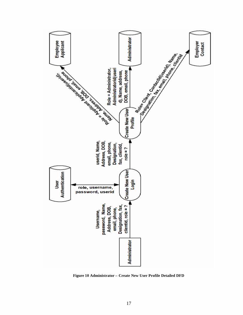
Figure 10 Administrator – Create New User Profile Detailed DFD
18
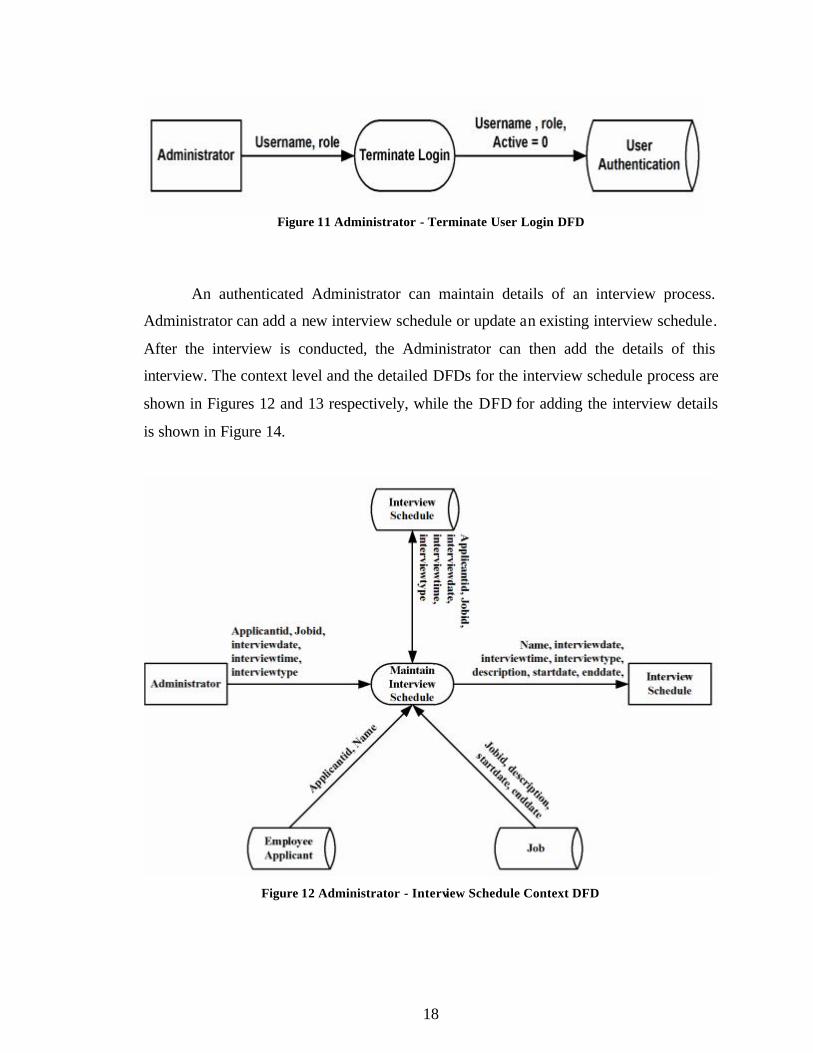
Figure 11 Administrator - Terminate User Login DFD
An authenticated Administrator can maintain details of an interview process.
Administrator can add a new interview schedule or update an existing interview schedule.
After the interview is conducted, the Administrator can then add the details of this
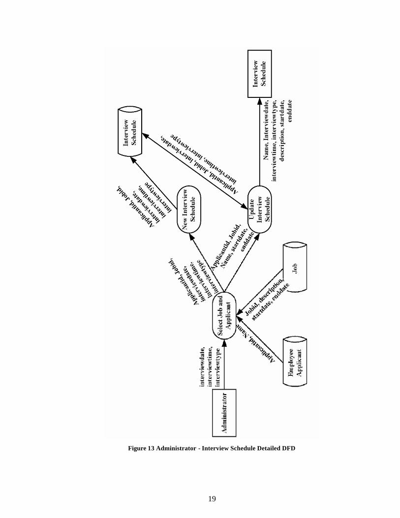
interview. The context level and the detailed DFDs for the interview schedule process are
shown in Figures 12 and 13 respectively, while the DFD for adding the interview details
is shown in Figure 14.
Figure 12 Administrator - Interview Schedule Context DFD
19
Figure 13 Administrator - Interview Schedule Detailed DFD
20
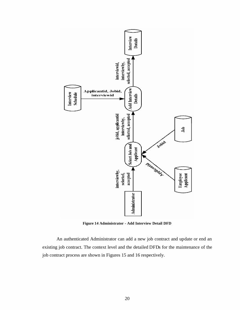
Figure 14 Administrator - Add Interview Detail DFD
An authenticated Administrator can add a new job contract and update or end an
existing job contract. The context level and the detailed DFDs for the maintenance of the
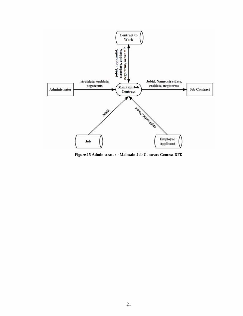
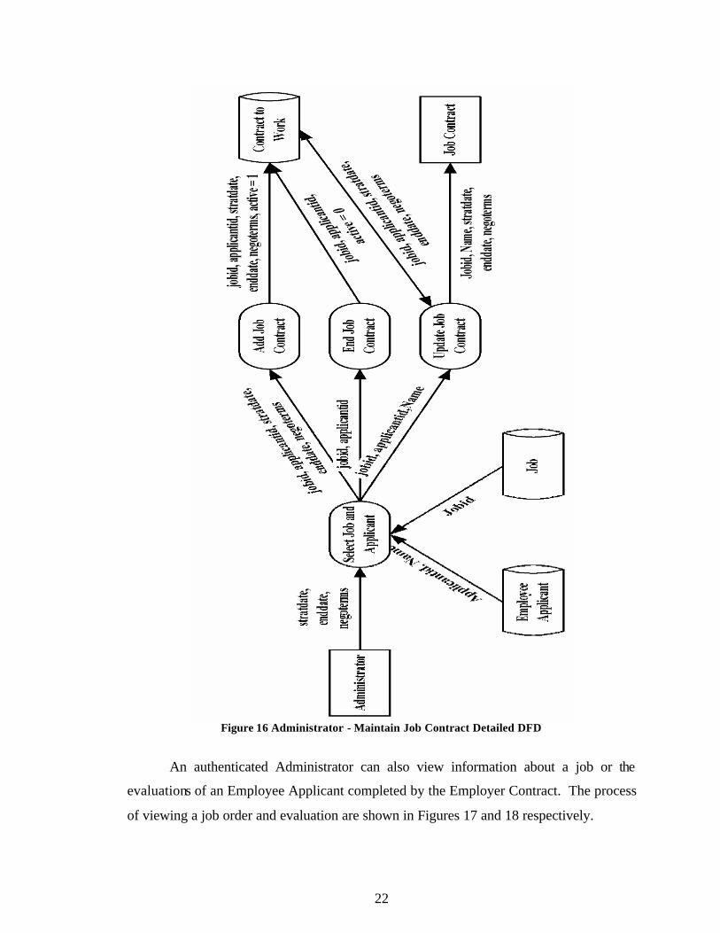
job contract process are shown in Figures 15 and 16 respectively.
21
Figure 15 Administrator - Maintain Job Contract Context DFD
22
Figure 16 Administrator - Maintain Job Contract Detailed DFD
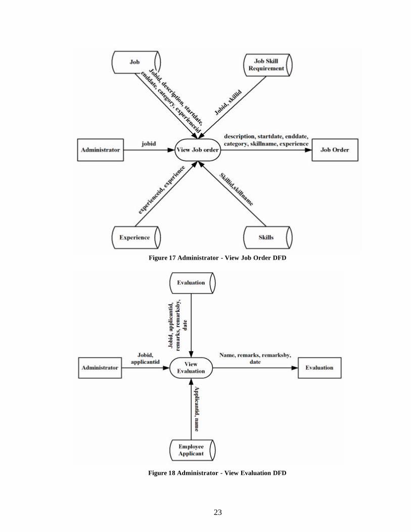
An authenticated Administrator can also view information about a job or the
evaluations of an Employee Applicant completed by the Employer Contract. The process
of viewing a job order and evaluation are shown in Figures 17 and 18 respectively.
23
Figure 17 Administrator - View Job Order DFD
Figure 18 Administrator - View Evaluation DFD
24
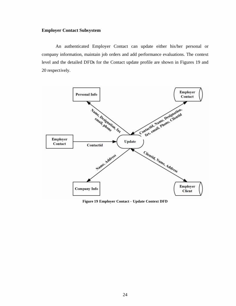
Employer Contact Subsystem
An authenticated Employer Contact can update either his/her personal or
company information, maintain job orders and add performance evaluations. The context
level and the detailed DFDs for the Contact update profile are shown in Figures 19 and
20 respectively.
Figure 19 Employer Contact - Update Context DFD
25
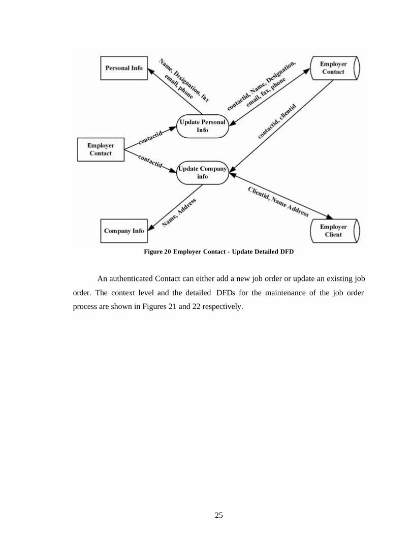
Figure 20 Employer Contact - Update Detailed DFD
An authenticated Contact can either add a new job order or update an existing job
order. The context level and the detailed DFDs for the maintenance of the job order
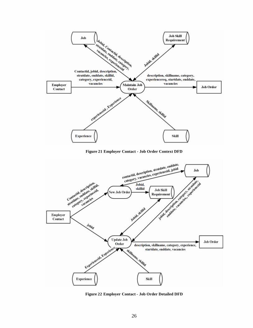
process are shown in Figures 21 and 22 respectively.
26
Figure 21 Employer Contact - Job Order Context DFD
Figure 22 Employer Contact - Job Order Detailed DFD
27
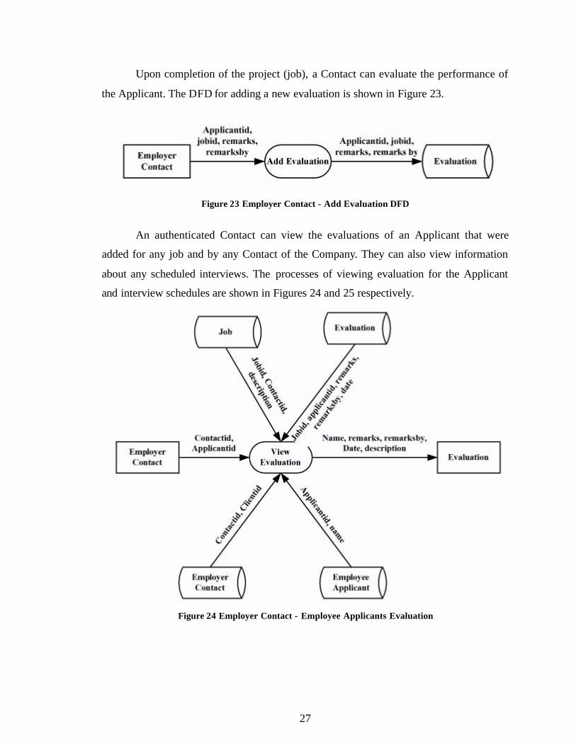
Upon completion of the project (job), a Contact can evaluate the performance of
the Applicant. The DFD for adding a new evaluation is shown in Figure 23.
Figure 23 Employer Contact - Add Evaluation DFD
An authenticated Contact can view the evaluations of an Applicant that were
added for any job and by any Contact of the Company. They can also view information
about any scheduled interviews. The processes of viewing evaluation for the Applicant
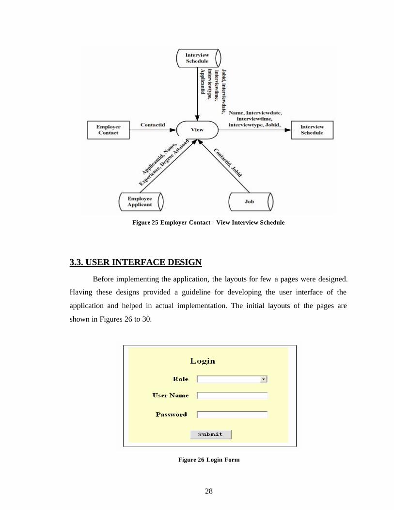
and interview schedules are shown in Figures 24 and 25 respectively.
Figure 24 Employer Contact - Employee Applicants Evaluation
28
Figure 25 Employer Contact - View Interview Schedule
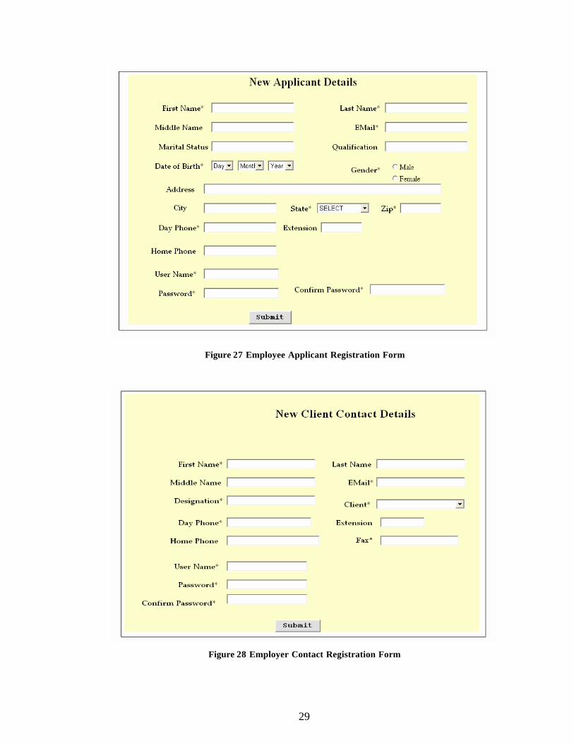
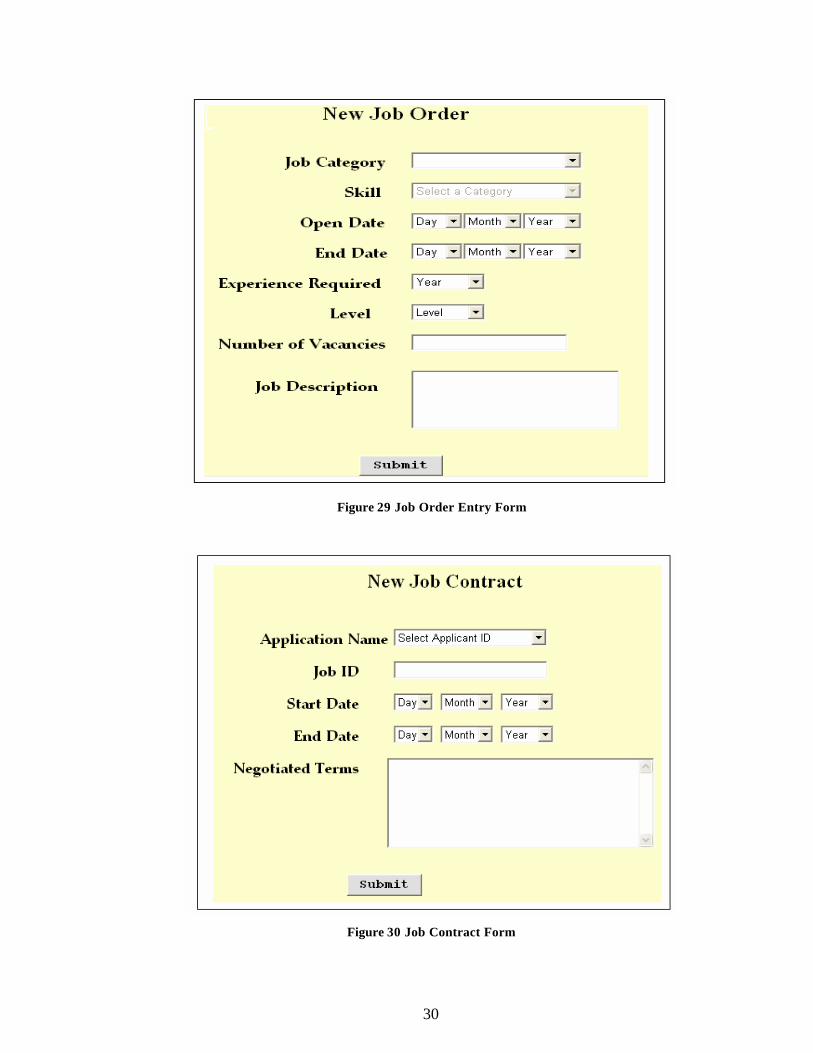
3.3. USER INTERFACE DESIGN
Before implementing the application, the layouts for few a pages were designed.
Having these designs provided a guideline for developing the user interface of the
application and helped in actual implementation. The initial layouts of the pages are
shown in Figures 26 to 30.
Figure 26 Login Form
29
Figure 27 Employee Applicant Registration Form
Figure 28 Employer Contact Registration Form
30
Figure 29 Job Order Entry Form
Figure 30 Job Contract Form
31
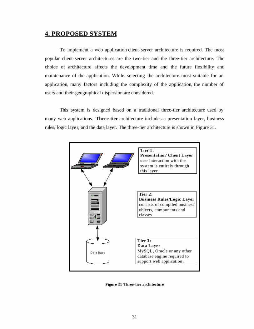
4. PROPOSED SYSTEM
To implement a web application client-server architecture is required. The most
popular client-server architectures are the two-tier and the three-tier architecture. The
choice of architecture affects the development time and the future flexibility and
maintenance of the application. While selecting the architecture most suitable for an
application, many factors including the complexity of the application, the number of
users and their geographical dispersion are considered.
This system is designed based on a traditional three-tier architecture used by
many web applications. Three-tier architecture includes a presentation layer, business
rules/ logic layer, and the data layer. The three-tier architecture is shown in Figure 31.
Data Base
Tier 1: Presentation/ Client Layer user interaction with the system is entirely through this layer.
Tier 2: Business Rules/Logic Layer consists of compiled business objects, components and classes
Tier 3: Data Layer MySQL , Oracle or any other database engine required to support web application .
Figure 31 Three-tier architecture
32
The three-tier architecture is generally used when an effective distributed
client/server design is needed that provides
• increased performance
• flexibility
• maintainability
• reusability and
• scalability
This model hides the complexity of distributed processing from the user. These
features have made the three-tier architecture a popular choice over the two-tier
architecture for Internet applications. The three layers are discussed below.
The Data layer is responsible for data storage. Primarily this tier (layer) consists
of one or more relational databases and/or file systems.
The Business Rules/Logic layer is the middleman between the presentation layer
and the data layer. This middle tier was introduced to overcome the deployment
limitation (whenever the application logic changed the application had to be redistributed
at each and every client) in the two-tier architecture. The middle tier provides process
management where business logic and rules are executed and can accommodate hundreds
of users.
The Presentation Layer, also called the Client tier, is responsible for the
presentation of data, receiving user events, and controlling the user interface. The user
interaction with the system is entirely through this layer.
33
5. IMPLEMENTATION TECHNOLOGIES
To implement any web-based application a web server is required. A web server
is a piece of software that manages web pages and makes them available to the ‘client’
browser – via a local network or over the Internet. The web server can be accessed
remotely or locally. There are many web servers available such as Apache, Internet
Information Services IIS, Netscape Web Server and so on.
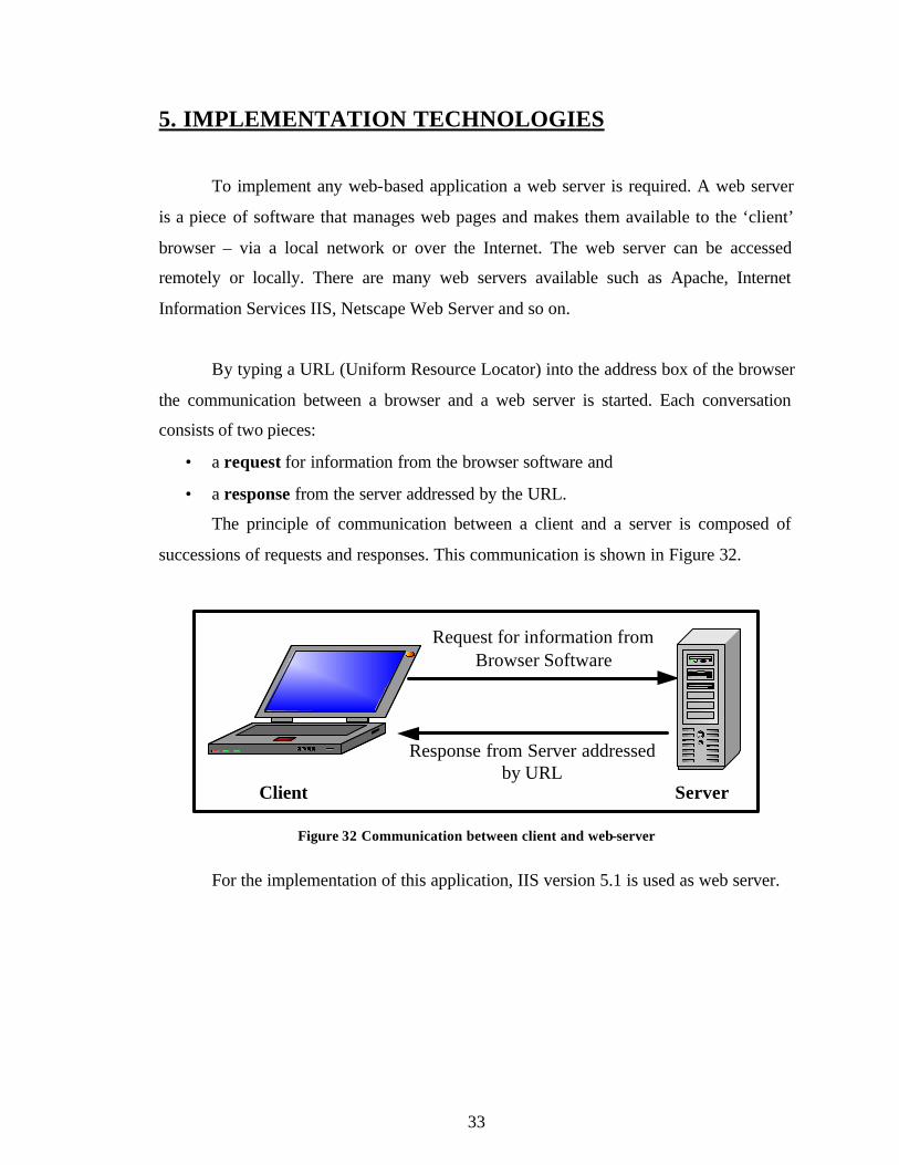
By typing a URL (Uniform Resource Locator) into the address box of the browser
the communication between a browser and a web server is started. Each conversation
consists of two pieces:
• a request for information from the browser software and
• a response from the server addressed by the URL.
The principle of communication between a client and a server is composed of
successions of requests and responses. This communication is shown in Figure 32.
Request for information from Browser Software
Client Server
Response from Server addressed by URL
Figure 32 Communication between client and web-server
For the implementation of this application, IIS version 5.1 is used as web server.
34
5.1. IIS
IIS (Internet Information Services) is a group of Internet servers including a
Web or Hypertext Transfer Protocol server and a File Transfer Protocol server. IIS is
Microsoft's entry to compete in the Internet server market that is also addressed by
Apache, Sun Microsystems (Sun Java System Web Server), O'Reilly and others. The
current version of IIS is 7.0 for Windows Vista, 6.0 for Windows Server 2003 and IIS 5.1
for Windows XP Professional. IIS 5.1 for Windows XP is a restricted version of IIS that
supports only 10 simultaneous connections and a single web site [15].
The web server itself cannot directly perform server side processing but can
delegate the task to ISAPI (Internet Server Application Program Interface) applications
on the server. Microsoft provides a number of these ISAPI applications including one for
Active Server Page and one for ASP.NET.
A typical company that buys IIS can create pages for Web sites. There are two
types of web pages, static and dynamic web pages. The static web pages are discussed
in detailed in section 5.1.1 and the dynamic web pages are discussed in section 5.1.2.
5.1.1 Static Web pages
A Static web page consists of some HTML code typed directly into a text editor
and saved as a .htm or .html file. The content and appearance of these web pages is
always the same, regardless of who visits the page, or when they visit, or how they arrive
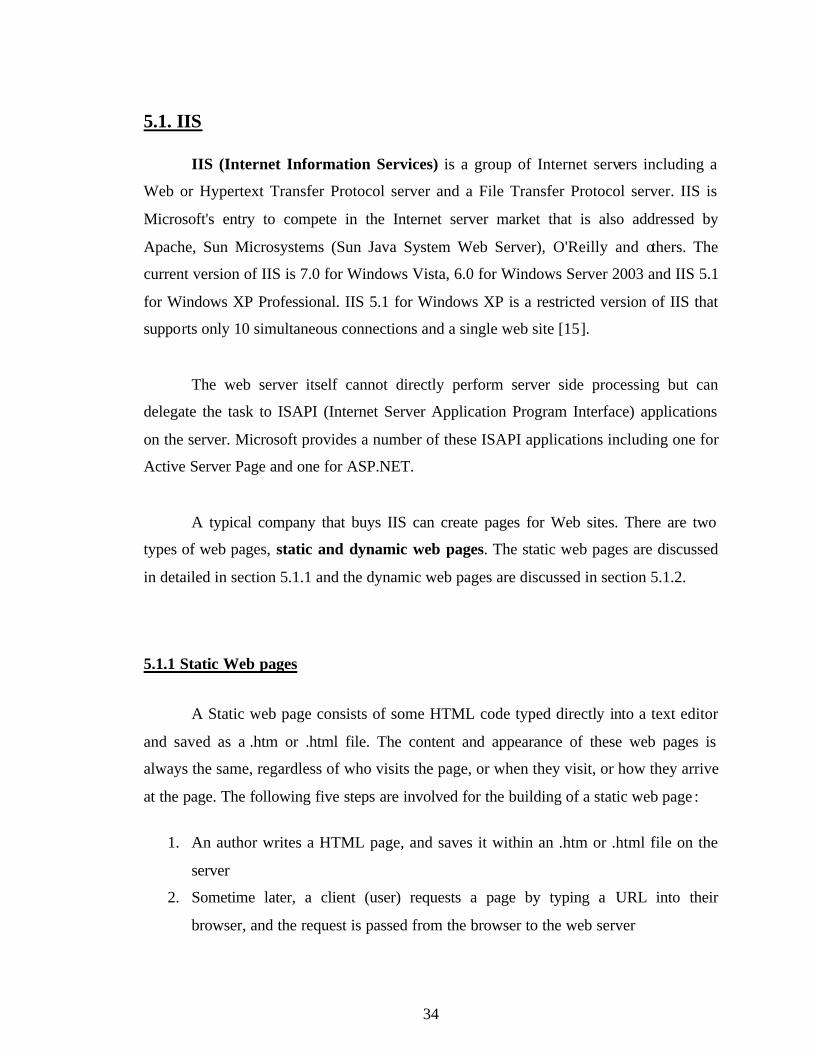
at the page. The following five steps are involved for the building of a static web page :
1. An author writes a HTML page, and saves it within an .htm or .html file on the
server
2. Sometime later, a client (user) requests a page by typing a URL into their
browser, and the request is passed from the browser to the web server
35
3. The web server locates the .htm or .html page and converts it to an HTML stream
4. The web server sends the HTML stream back across the network to the browser
5. The browser processes the HTML and displays the page
Figure 33 shows the steps involved in creating a static web page
Web Server
Client
1. Author writes HTML
2. Client request a web page
3. Web server locates the .html file
4. HTML stream returned to browser
5. Browser processes the HTML and
displays the web page
Figure 33 Steps for creating a Static Web Page [8]
There are several limitations for Static Web Pages. HTML offers no features for
personalizing the web pages. Each web page that is served is the same for every user who
request the page. The other limitation is that there is also no security with HTML as the
code can be viewed by everybody. Though Static pages are very fast to download, as
quickly as copying a small file over a network, they are quite limited without any
dynamic features.
36
5.1.2. Dynamic Web Pages
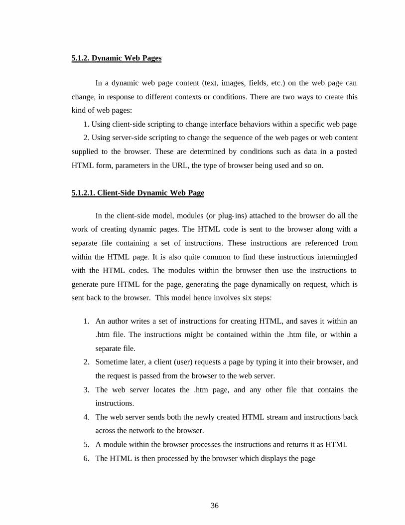
In a dynamic web page content (text, images, fields, etc.) on the web page can
change, in response to different contexts or conditions. There are two ways to create this
kind of web pages:
1. Using client-side scripting to change interface behaviors within a specific web page
2. Using server-side scripting to change the sequence of the web pages or web content
supplied to the browser. These are determined by conditions such as data in a posted
HTML form, parameters in the URL, the type of browser being used and so on.
5.1.2.1. Client-Side Dynamic Web Page
In the client-side model, modules (or plug- ins) attached to the browser do all the
work of creating dynamic pages. The HTML code is sent to the browser along with a
separate file containing a set of instructions. These instructions are referenced from
within the HTML page. It is also quite common to find these instructions intermingled
with the HTML codes. The modules within the browser then use the instructions to
generate pure HTML for the page, generating the page dynamically on request, which is
sent back to the browser. This model hence involves six steps:
1. An author writes a set of instructions for creating HTML, and saves it within an
.htm file. The instructions might be contained within the .htm file, or within a
separate file.
2. Sometime later, a client (user) requests a page by typing it into their browser, and
the request is passed from the browser to the web server.
3. The web server locates the .htm page, and any other file that contains the
instructions.
4. The web server sends both the newly created HTML stream and instructions back
across the network to the browser.
5. A module within the browser processes the instructions and returns it as HTML
6. The HTML is then processed by the browser which displays the page
37
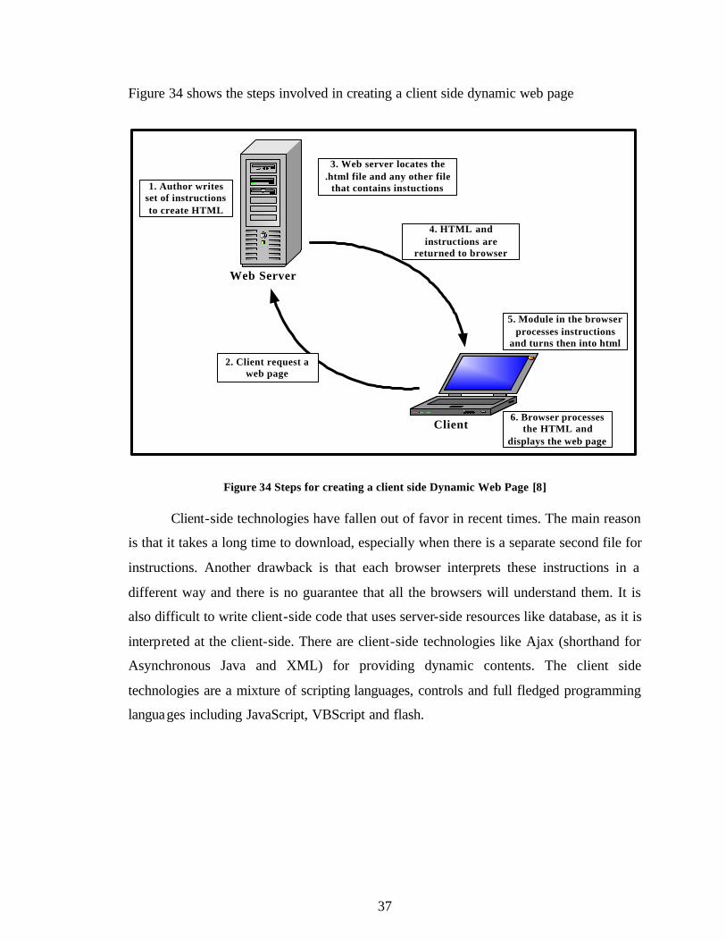
Figure 34 shows the steps involved in creating a client side dynamic web page
Web Server
Client
1. Author writes set of instructions to create HTML
2. Client request a web page
3. Web server locates the .html file and any other file
that contains instuctions
4. HTML and instructions are
returned to browser
6. Browser processes the HTML and
displays the web page
5. Module in the browser processes instructions
and turns then into html
Figure 34 Steps for creating a client side Dynamic Web Page [8]
Client-side technologies have fallen out of favor in recent times. The main reason
is that it takes a long time to download, especially when there is a separate second file for
instructions. Another drawback is that each browser interprets these instructions in a
different way and there is no guarantee that all the browsers will understand them. It is
also difficult to write client-side code that uses server-side resources like database, as it is
interpreted at the client-side. There are client-side technologies like Ajax (shorthand for
Asynchronous Java and XML) for providing dynamic contents. The client side
technologies are a mixture of scripting languages, controls and full fledged programming
languages including JavaScript, VBScript and flash.
38
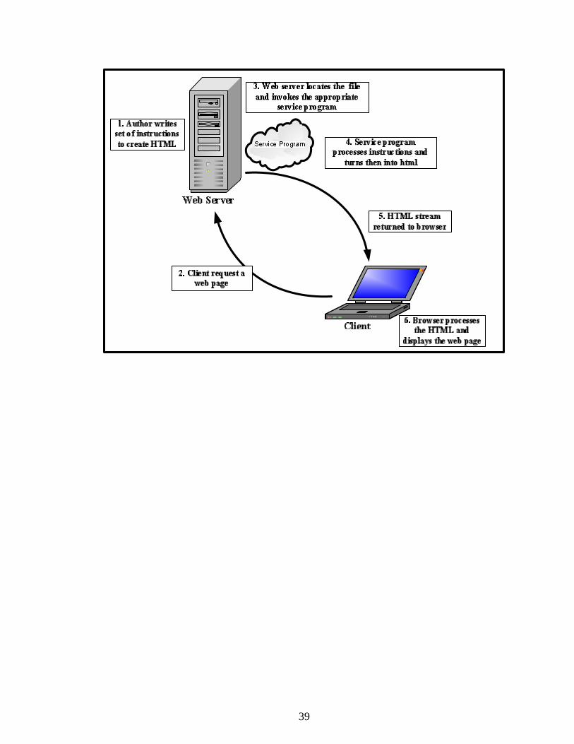
5.1.2.2. Server-Side Dynamic Web Page
In the server-side model, when a user types a page request such as an ASP, PHP
or ASP.NET page, the web server locates the page and invokes the appropriate servicing
program. The servicing program is not part of the Web server but it is an independent
executable program running on the Web server. The servicing program, processes any
user input, determines the action that must be taken, interacts with any external sources
and finally produces an HTML document and terminates. The Web server then sends the
HTML document back to the user’s browser where it is displayed. The page is thus
generated dynamically upon request. The six steps involved in developing a server side
dynamic web page are
1. A web author writes a set of instructions for creating HTML, and saves these
instructions within a file such as a .php or .asp or .aspx file
2. Sometime later, a user types a page request into their browser, and the request is
passed from the browser to the web server
3. The web server locates the file of instructions and invokes the appropriate
servicing program
4. The servicing program follows the instructions in order to create a stream of
HTML
5. The web server sends the newly created HTML stream back across the network to
the browser
6. The browser processes the HTML and displays the page
Figure 35 shows the steps involved in creating a server side dynamic web page
39
Figure 35 Steps for creating server side Dynamic Web Page
In this model all the processing is done on the server, before the page is sent back
to the browser. One of the key advantages of this model over the client-side model is that
only the HTML code describing the finished page is actually sent to the browser. The
logic of the page is thus hidden away on the server.
There are several server side technologies for providing dynamic contents
including ASP, JSP, ColdFusion, PHP and ASP.NET. For the implementation of this
project ASP.NET is used and is discussed in detail in section 5.2.
40
5.2. ASP.NET
ASP.NET is a server-side technology for creating dynamic web pages and
interactive web applications. It uses any full- fledged programming languages supported
by .NET such as C#, VB.NET and Java. VB.NET is the programming language used for
the implementation of this application.
ASP.NET is a library of classes designed to handle HTTP requests. In addition to
a class library, it also includes several IIS components for managing requests such as the
ISAPI DLL named aspnet_isapi.dll and a worker process named aspnet_wp.exe. These
components are explained below and shown in Figure 36.
An ASP.NET page is an HTML page that contains server-side scripts that are
processed by a web server before being sent to the user’s browser. It relies on a module
attached to the web server. The ASP.NET module is aspnet_isapi.dll. ASP.NET installs
new mappings in IIS, redirecting file requests for aspx, ascx and so on to aspnet_isapi.dll.
From there, aspnet_isapi.dll directs the request to the aspnet_wp.exe [4].
ASP.NET runs as a process of its own, aspnet_wp.exe, unlike classic ASP which
runs in the same memory space as the IIS. It simply uses IIS to receive requests and then
to send out the responses. Therefore, the ASP.NET process can be created or destroyed
without affecting IIS at all. This worker process manages the ASP.NET pipeline, the
route through which requests flow within ASP.NET [11].
41
IIS(5.0)(inetinfo.exe)
Aspnet_isapi.dll
Aspnet_filter.dll ASP.NETWorker Process(aspnet_wp.exe)
Web Application
ASP.NET State Service
(aspnet_stat.exe)
Named Pipe
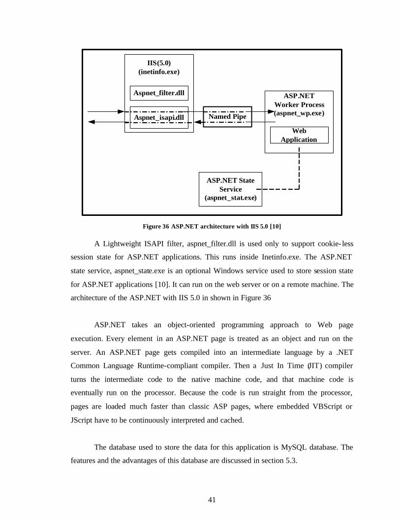
Figure 36 ASP.NET architecture with IIS 5.0 [10]
A Lightweight ISAPI filter, aspnet_filter.dll is used only to support cookie- less
session state for ASP.NET applications. This runs inside Inetinfo.exe. The ASP.NET
state service, aspnet_state.exe is an optional Windows service used to store session state
for ASP.NET applications [10]. It can run on the web server or on a remote machine. The
architecture of the ASP.NET with IIS 5.0 in shown in Figure 36
ASP.NET takes an object-oriented programming approach to Web page
execution. Every element in an ASP.NET page is treated as an object and run on the
server. An ASP.NET page gets compiled into an intermediate language by a .NET
Common Language Runtime-compliant compiler. Then a Just In Time (JIT) compiler
turns the intermediate code to the native machine code, and that machine code is
eventually run on the processor. Because the code is run straight from the processor,
pages are loaded much faster than classic ASP pages, where embedded VBScript or
JScript have to be continuously interpreted and cached.
The database used to store the data for this application is MySQL database. The
features and the advantages of this database are discussed in section 5.3.
42
5.3. MySQL
MySQL is a software package that enables the creation, maintenance and
management of database. MySQL is a Structured Query Language (SQL) based,
client/server relational database. Each of these terms describes a fundamental part of the
architecture of MySQL Server.
Database: A database is a storage place for data. The user runs an application that
accesses data from the database and presents it to the user in an understandable format.
Relational Database: There are different ways to organize data in a database but
relational databases are one of the most effective. Relational database systems are an
application of mathematical set theory to the problem of effectively organizing data. In a
relational database, data is collected into tables (called relations in relational theory).
Structured Query Language (SQL): There are several different languages that
can be used to manipulate relational databases. The most common of the languages is
SQL. The American National Standards Institute (ANSI) and the International Standards
Organization (ISO) have defined standards for SQL. Data within a database can be
retrieved via SQL that is based on Relational Algebra.
Client/Server: In a client/server system, the server is a relatively large computer
in a central location that manages a resource used by many people. When individuals
need to use the resource, they connect over the network from their computers, clients, to
the server.
MySQL’s specific design goals were speed, robustness and ease of use. To
improve the performance, MySQL was made as a multithreaded database engine. A
multithreaded application performs many tasks at the same time as if multiple instances
of that application were running simultaneously. Multithreaded applications have a lower
overhead cost, when compared with multi processed databases.
43
In being multithreaded, MySQL has many advantages. A separate thread handles
each incoming connection with an extra thread that is always running to manage the
connections. Multiple clients can perform read operations simultaneously, but while
writing, only the clients that need access to the data being updated are held. Even though
the threads share the same process space, they execute individually. Because of this
separation, multiprocessor machines can spread the thread across many CPUs as long as
the host operating system supports multiple CPUs. Multithreading is the key feature to
support MySQL’s performance design goals and this is the core feature around which
MySQL is built [9]. MySQL has other features but the most attracting features are cost
and performance.
44
6. CONNECTING TO THE DATABASE
In this application ASP.NET uses ADO.NET to connect to the MySQL database.
ADO.NET is discussed in detail in section 6.1
6.1. ADO.NET
ADO (ActiveX Data Object) is Microsoft’s programming interface for data
access. Though a good architecture, ADO has some disadvantages. It has a connection
oriented data access, that is; the connection to the database remained open until the
application was closed. The open connection raised concerns of database security and
network traffic. The connections also use maximum system resources making system
performance less effective. To cope with these disadvantages of ADO, ADO.NET was
designed. ADO.NET is a connection- less approach to data access. In ADO.NET when an
application interacts with a database, the connection is opened to serve a request and as
soon as the request is served the connection is closed.
ADO.NET is a set of software components used to access and modify data.
ADO.NET is part of the .NET framework. It is mainly used to access data stored in
relational database, though it can also be used to access data in non-relational data
sources including flat file database based on ISAM (Indexed Storage Access Method) or
VSAM (Indexed Storage Access Method) and hierarchical databases. ASP.NET uses
ADO.NET to connect to the database. The architecture of ADO.NET is shown in Figure
37.
45
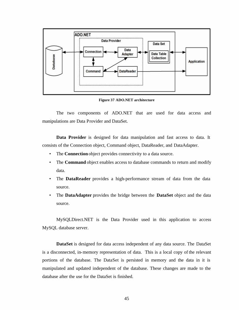
Figure 37 ADO.NET architecture
The two components of ADO.NET that are used for data access and
manipulations are Data Provider and DataSet.
Data Provider is designed for data manipulation and fast access to data. It
consists of the Connection object, Command object, DataReader, and DataAdapter.
• The Connection object provides connectivity to a data source.
• The Command object enables access to database commands to return and modify
data.
• The DataReader provides a high-performance stream of data from the data
source.
• The DataAdapter provides the bridge between the DataSet object and the data
source.
MySQLDirect.NET is the Data Provider used in this application to access
MySQL database server.
DataSet is designed for data access independent of any data source. The DataSet
is a disconnected, in-memory representation of data. This is a local copy of the relevant
portions of the database. The DataSet is persisted in memory and the data in it is
manipulated and updated independent of the database. These changes are made to the
database after the use for the DataSet is finished.
46
The DataSet contains a collection of one or more DataTable objects made up of
rows and columns of data, as well as primary key, foreign key, constraint, and relation
information about the data.
The application can connect to a database using either a DataReader or a
combination of DataSet and a DataAdapter. While deciding whether the application
should use a DataReader or a DataSet, the functionality of the application should be
considered. According to Microsoft [16], DataSet is a preferred choice for an application
that
• need to cache the data locally for manipulating
• interact with data dynamically, such as binding to a Windows Forms control
• perform extensive processing on data without requiring an open connection to the
data source, which frees the connection to be used by other clients.
If the above functionalities are not required then using the DataReader can boost
performance of the system. This is because the memory that would be consumed by the
DataSet is saved and the processing required to create and fill the contents of the
DataSet is not required. This application uses both DataSet and DataReader to read the
data. Command object called ExecuteNonQuery is used to write the data into the
database.
47
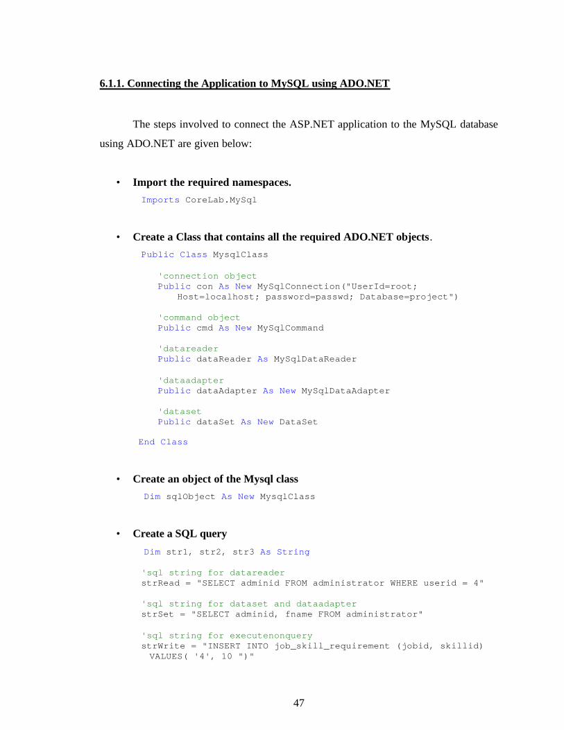
6.1.1. Connecting the Application to MySQL using ADO.NET
The steps involved to connect the ASP.NET application to the MySQL database
using ADO.NET are given below:
• Import the required namespaces. Imports CoreLab.MySql
• Create a Class that contains all the required ADO.NET objects. Public Class MysqlClass
'connection object Public con As New MySqlConnection("UserId=root;
Host=localhost; password=passwd; Database=project")
'command object Public cmd As New MySqlCommand
'datareader Public dataReader As MySqlDataReader 'dataadapter Public dataAdapter As New MySqlDataAdapter 'dataset Public dataSet As New DataSet
End Class
• Create an object of the Mysql class Dim sqlObject As New MysqlClass
• Create a SQL query
Dim str1, str2, str3 As String
'sql string for datareader strRead = "SELECT adminid FROM administrator WHERE userid = 4"
'sql string for dataset and dataadapter strSet = "SELECT adminid, fname FROM administrator" 'sql string for executenonquery strWrite = "INSERT INTO job_skill_requirement (jobid, skillid) VALUES( '4', 10 ")"
48
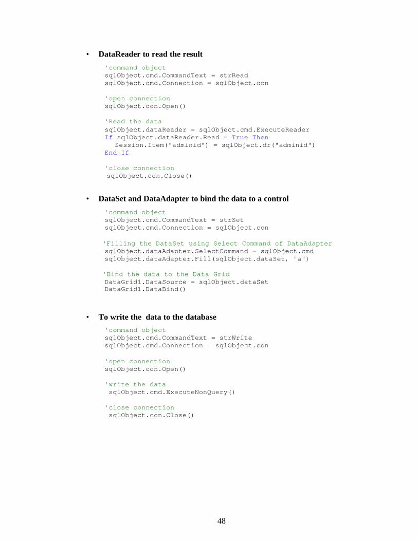
• DataReader to read the result
'command object sqlObject.cmd.CommandText = strRead sqlObject.cmd.Connection = sqlObject.con 'open connection sqlObject.con.Open() 'Read the data sqlObject.dataReader = sqlObject.cmd.ExecuteReader If sqlObject.dataReader.Read = True Then
Session.Item("adminid") = sqlObject.dr("adminid") End If 'close connection
sqlObject.con.Close()
• DataSet and DataAdapter to bind the data to a control
'command object sqlObject.cmd.CommandText = strSet
sqlObject.cmd.Connection = sqlObject.con 'Filling the DataSet using Select Command of DataAdapter sqlObject.dataAdapter.SelectCommand = sqlObject.cmd sqlObject.dataAdapter.Fill(sqlObject.dataSet, "a")
'Bind the data to the Data Grid DataGrid1.DataSource = sqlObject.dataSet
DataGrid1.DataBind()
• To write the data to the database 'command object sqlObject.cmd.CommandText = strWrite sqlObject.cmd.Connection = sqlObject.con 'open connection sqlObject.con.Open() 'write the data sqlObject.cmd.ExecuteNonQuery()
'close connection sqlObject.con.Close()
49
7. APPLICATION
The objective of this project is to implement a web-based application that
examines the issue related to dynamic Human Resource Management for a fictitious
consulting firm. The application provides features such as the employee database,
company database, interview scheduling, contracts management and performance report.
Some screenshots taken while running the application are shown below. The
functionalities are also explained accordingly.
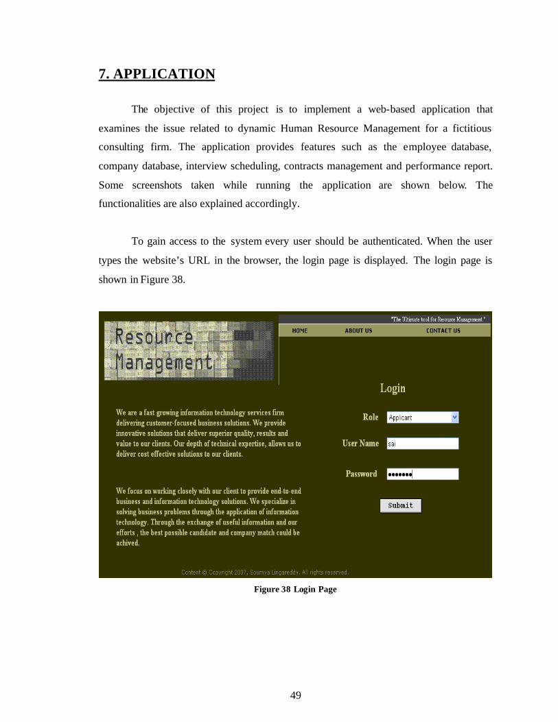
To gain access to the system every user should be authenticated. When the user
types the website’s URL in the browser, the login page is displayed. The login page is
shown in Figure 38.
Figure 38 Login Page
50
Depending on the role selected in the login page the user is directed to the
respective subsystem, the Employee Applicant subsystem, the Administrator subsystem
or the Employer Contact subsystem.
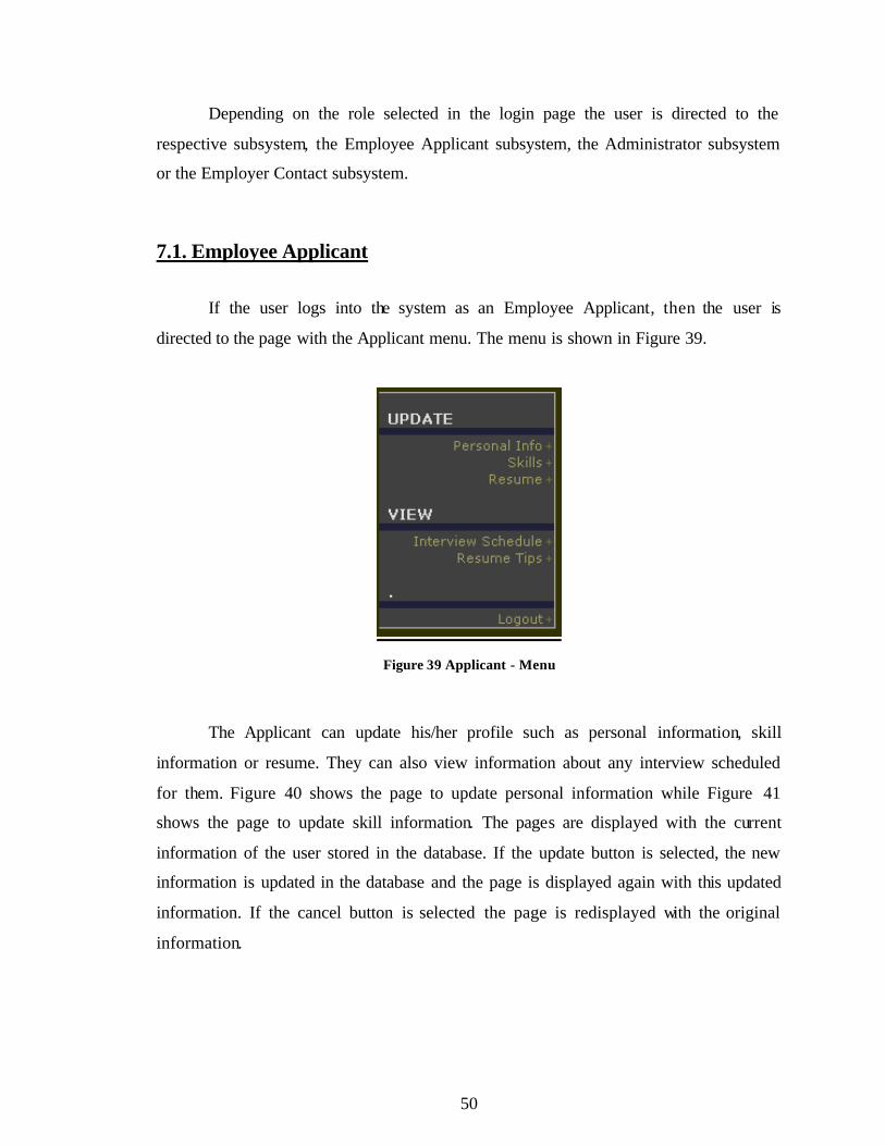
7.1. Employee Applicant
If the user logs into the system as an Employee Applicant, then the user is
directed to the page with the Applicant menu. The menu is shown in Figure 39.
Figure 39 Applicant - Menu
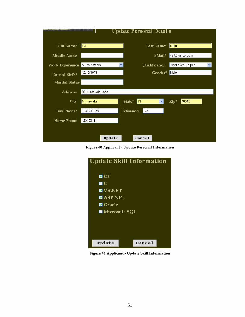
The Applicant can update his/her profile such as personal information, skill
information or resume. They can also view information about any interview scheduled
for them. Figure 40 shows the page to update personal information while Figure 41
shows the page to update skill information. The pages are displayed with the current
information of the user stored in the database. If the update button is selected, the new
information is updated in the database and the page is displayed again with this updated
information. If the cancel button is selected the page is redisplayed with the original
information.
51
Figure 40 Applicant - Update Personal Information
Figure 41 Applicant - Update Skill Information
52
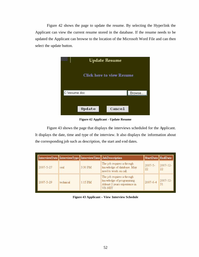
Figure 42 shows the page to update the resume. By selecting the Hyperlink the
Applicant can view the current resume stored in the database. If the resume needs to be
updated the Applicant can browse to the location of the Microsoft Word File and can then
select the update button.
Figure 42 Applicant - Update Resume
Figure 43 shows the page that displays the interviews scheduled for the Applicant.
It displays the date, time and type of the interview. It also displays the information about
the corresponding job such as description, the start and end dates.
Figure 43 Applicant – View Interview Schedule
53
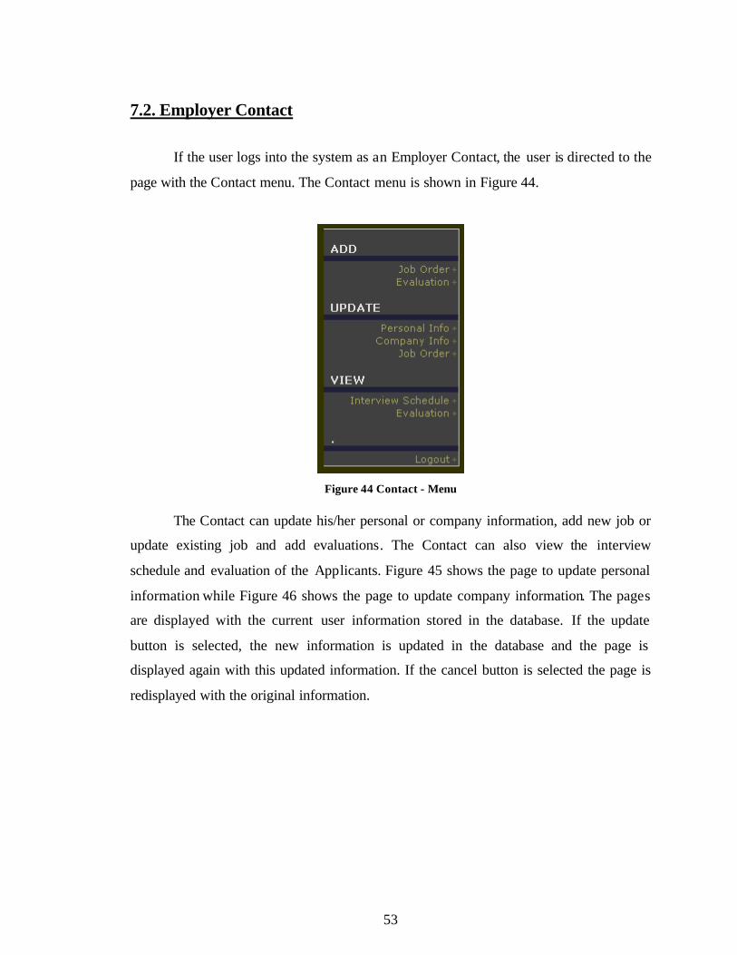
7.2. Employer Contact
If the user logs into the system as an Employer Contact, the user is directed to the
page with the Contact menu. The Contact menu is shown in Figure 44.
Figure 44 Contact - Menu
The Contact can update his/her personal or company information, add new job or
update existing job and add evaluations. The Contact can also view the interview
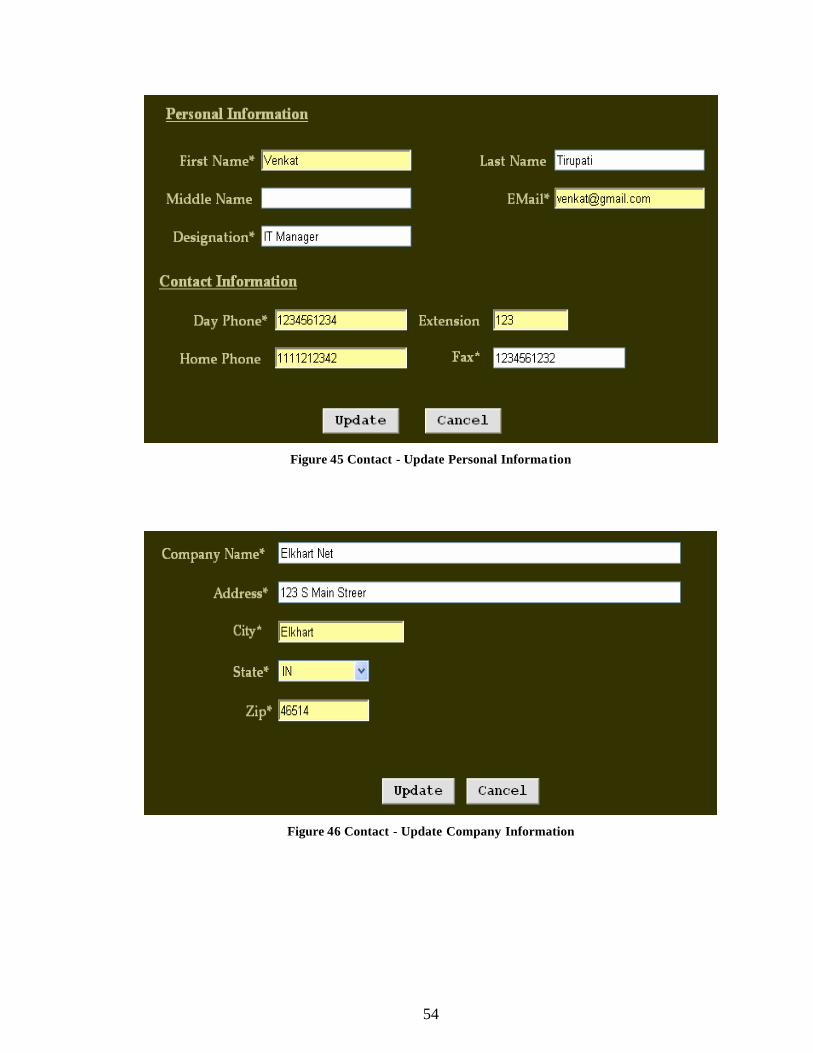
schedule and evaluation of the Applicants. Figure 45 shows the page to update personal
information while Figure 46 shows the page to update company information. The pages
are displayed with the current user information stored in the database. If the update
button is selected, the new information is updated in the database and the page is
displayed again with this updated information. If the cancel button is selected the page is
redisplayed with the original information.
54
Figure 45 Contact - Update Personal Information
Figure 46 Contact - Update Company Information
55
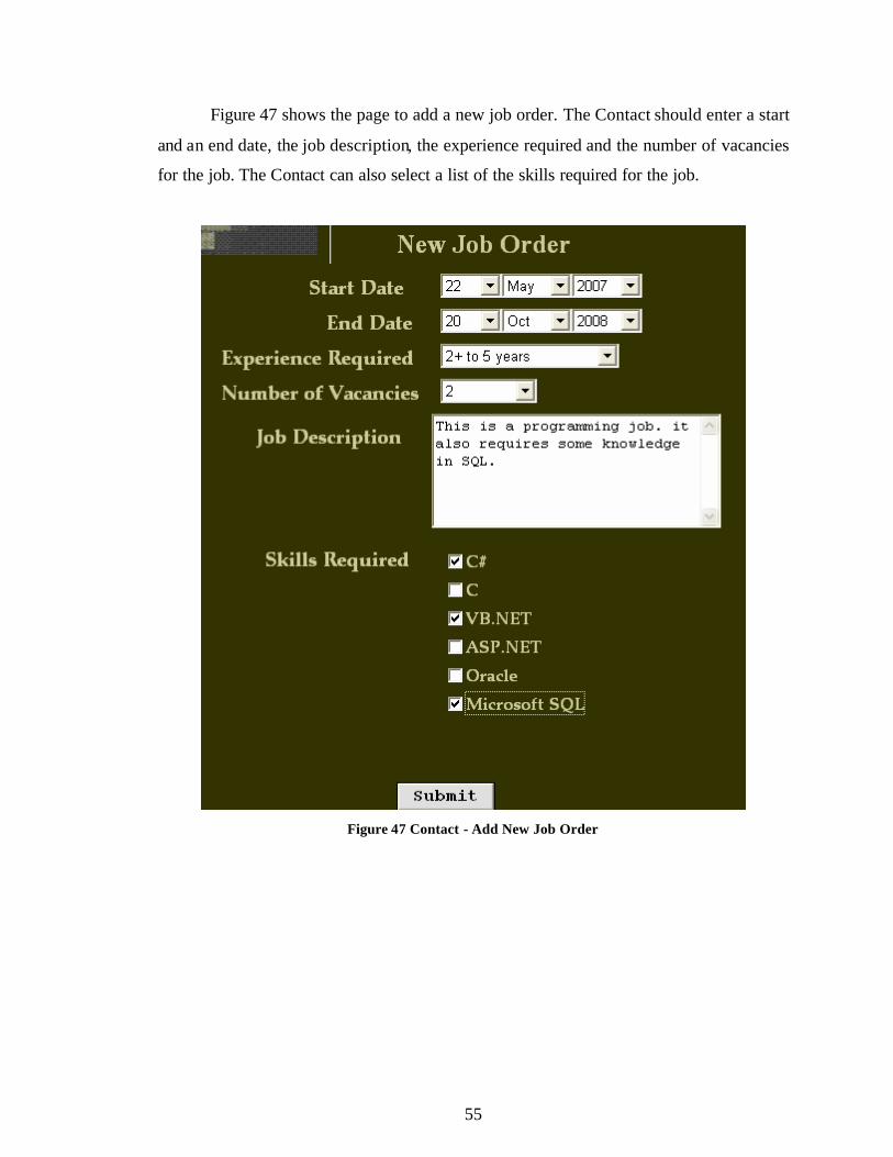
Figure 47 shows the page to add a new job order. The Contact should enter a start
and an end date, the job description, the experience required and the number of vacancies
for the job. The Contact can also select a list of the skills required for the job.
Figure 47 Contact - Add New Job Order
56
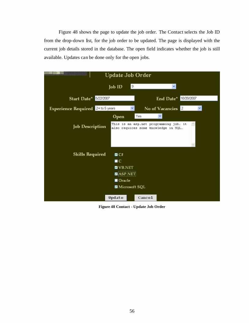
Figure 48 shows the page to update the job order. The Contact selects the Job ID
from the drop-down list, for the job order to be updated. The page is displayed with the
current job details stored in the database. The open field indicates whether the job is still
available. Updates can be done only for the open jobs.
Figure 48 Contact - Update Job Order
57
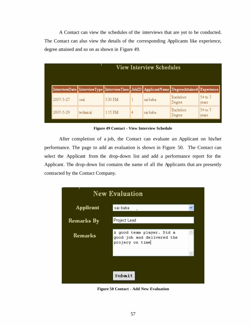
A Contact can view the schedules of the interviews that are yet to be conducted.
The Contact can also view the details of the corresponding Applicants like experience,
degree attained and so on as shown in Figure 49.
Figure 49 Contact - View Interview Schedule
After completion of a job, the Contact can evaluate an Applicant on his/her
performance. The page to add an evaluation is shown in Figure 50. The Contact can
select the Applicant from the drop-down list and add a performance report for the
Applicant. The drop-down list contains the name of all the Applicants that are presently
contracted by the Contact Company.
Figure 50 Contact - Add New Evaluation
58
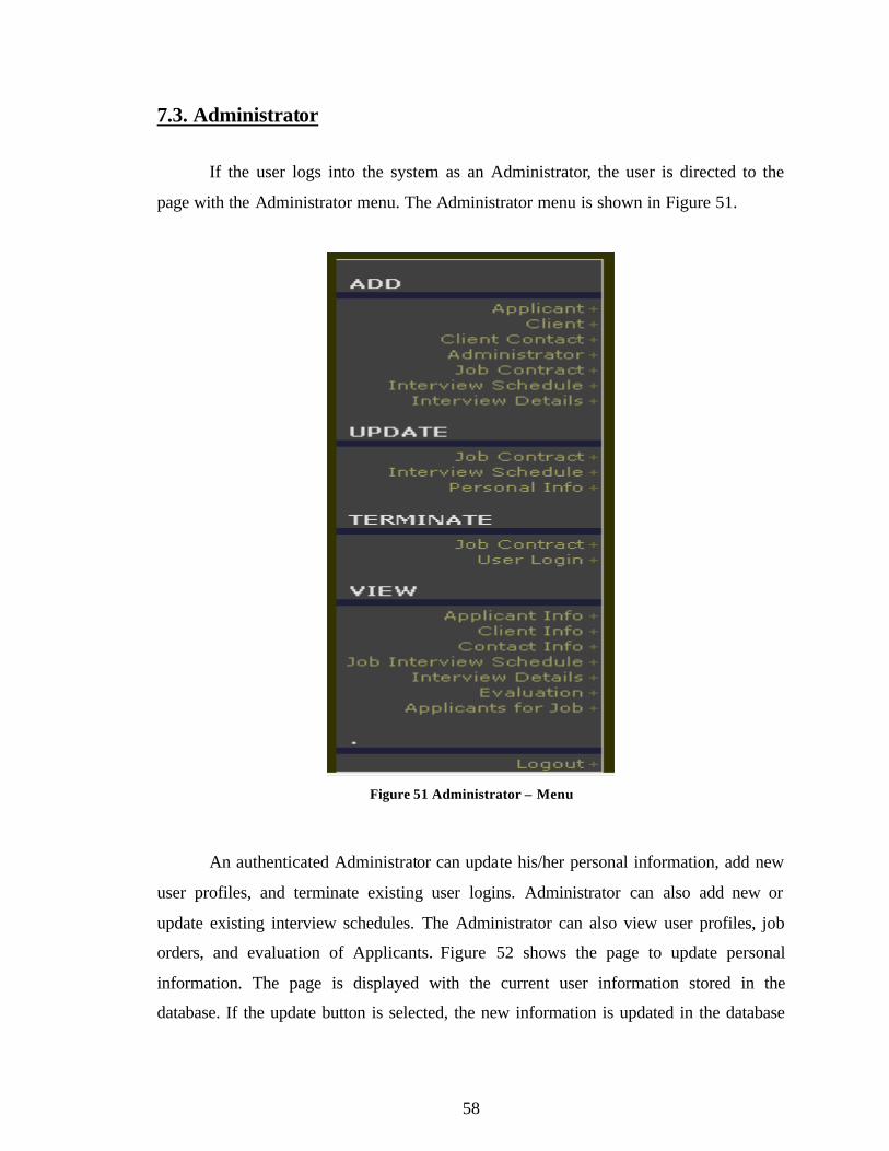
7.3. Administrator
If the user logs into the system as an Administrator, the user is directed to the
page with the Administrator menu. The Administrator menu is shown in Figure 51.
Figure 51 Administrator – Menu
An authenticated Administrator can update his/her personal information, add new
user profiles, and terminate existing user logins. Administrator can also add new or
update existing interview schedules. The Administrator can also view user profiles, job
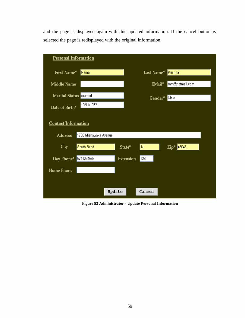
orders, and evaluation of Applicants. Figure 52 shows the page to update personal
information. The page is displayed with the current user information stored in the
database. If the update button is selected, the new information is updated in the database
59
and the page is displayed again with this updated information. If the cancel button is
selected the page is redisplayed with the original information.
Figure 52 Administrator - Update Personal Information
60
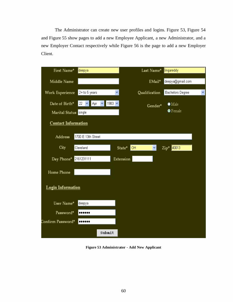
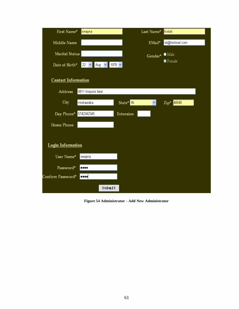
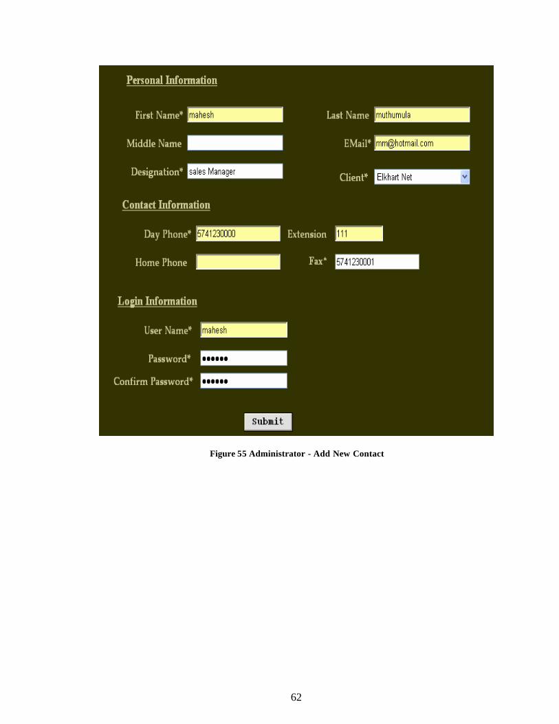
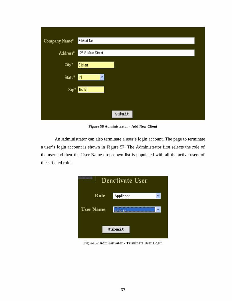
The Administrator can create new user profiles and logins. Figure 53, Figure 54
and Figure 55 show pages to add a new Employee Applicant, a new Administrator, and a
new Employer Contact respectively while Figure 56 is the page to add a new Employer
Client.
Figure 53 Administrator - Add New Applicant
61
Figure 54 Administrator - Add New Administrator
62
Figure 55 Administrator - Add New Contact
63
Figure 56 Administrator - Add New Client
An Administrator can also terminate a user’s login account. The page to terminate
a user’s login account is shown in Figure 57. The Administrator first selects the role of
the user and then the User Name drop-down list is populated with all the active users of
the selected role.
Figure 57 Administrator - Terminate User Login
64
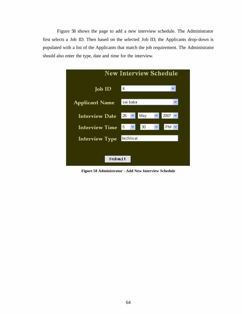
Figure 58 shows the page to add a new interview schedule. The Administrator
first selects a Job ID. Then based on the selected Job ID, the Applicants drop-down is
populated with a list of the Applicants that match the job requirement. The Administrator
should also enter the type, date and time for the interview.
Figure 58 Administrator - Add New Interview Schedule
65
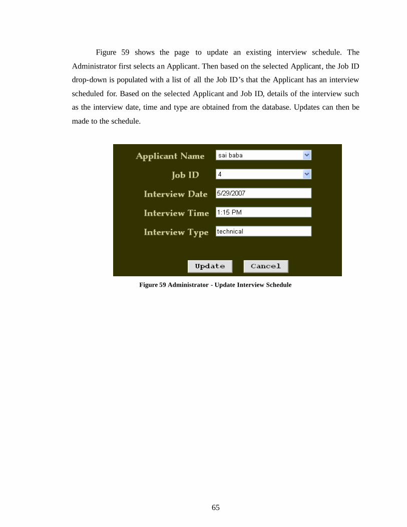
Figure 59 shows the page to update an existing interview schedule. The
Administrator first selects an Applicant. Then based on the selected Applicant, the Job ID
drop-down is populated with a list of all the Job ID’s that the Applicant has an interview
scheduled for. Based on the selected Applicant and Job ID, details of the interview such
as the interview date, time and type are obtained from the database. Updates can then be
made to the schedule.
Figure 59 Administrator - Update Interview Schedule
66
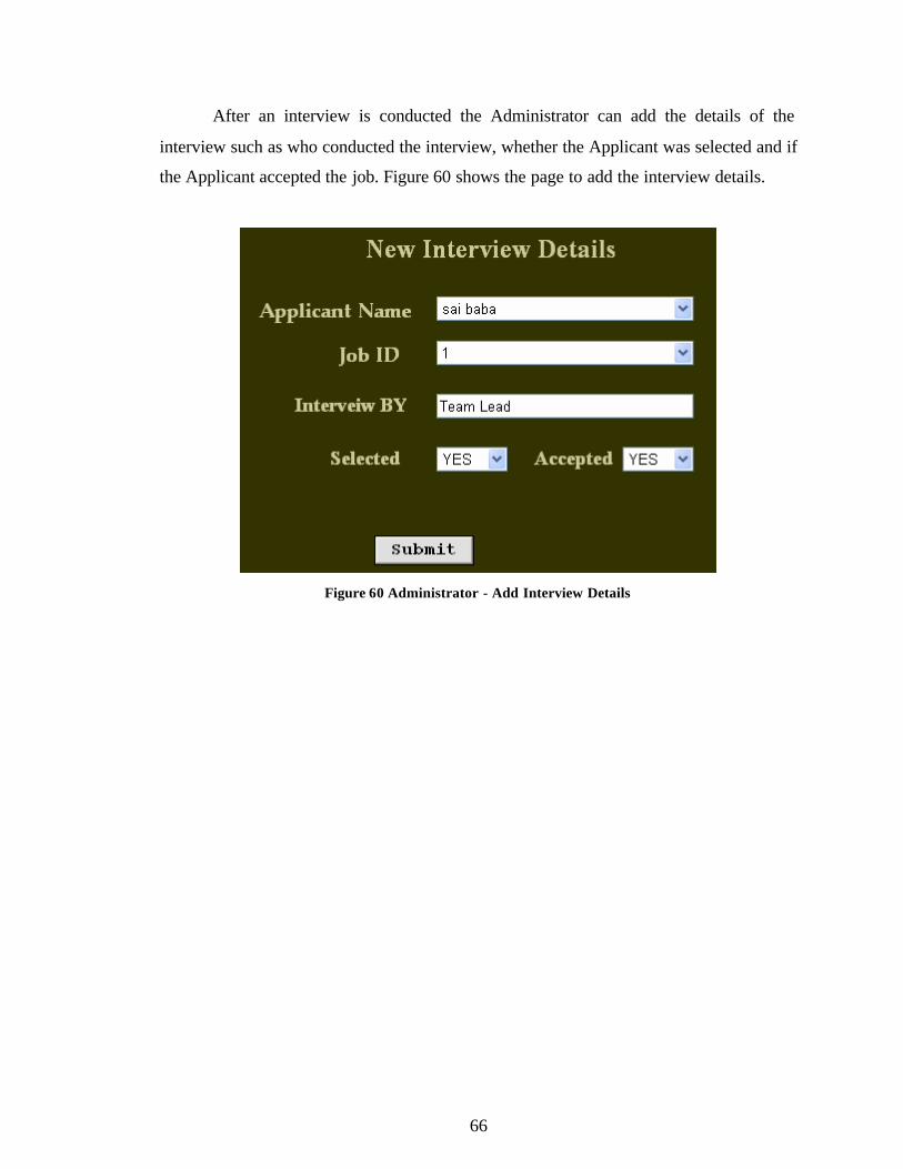
After an interview is conducted the Administrator can add the details of the
interview such as who conducted the interview, whether the Applicant was selected and if
the Applicant accepted the job. Figure 60 shows the page to add the interview details.
Figure 60 Administrator - Add Interview Details
67
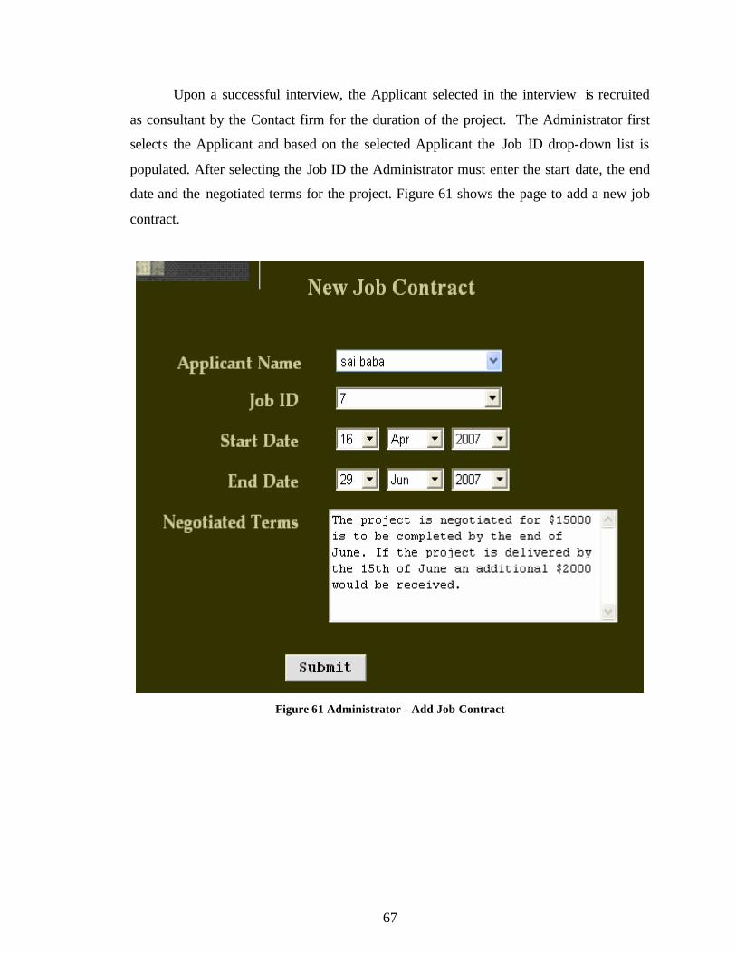
Upon a successful interview, the Applicant selected in the interview is recruited
as consultant by the Contact firm for the duration of the project. The Administrator first
selects the Applicant and based on the selected Applicant the Job ID drop-down list is
populated. After selecting the Job ID the Administrator must enter the start date, the end
date and the negotiated terms for the project. Figure 61 shows the page to add a new job
contract.
Figure 61 Administrator - Add Job Contract
68
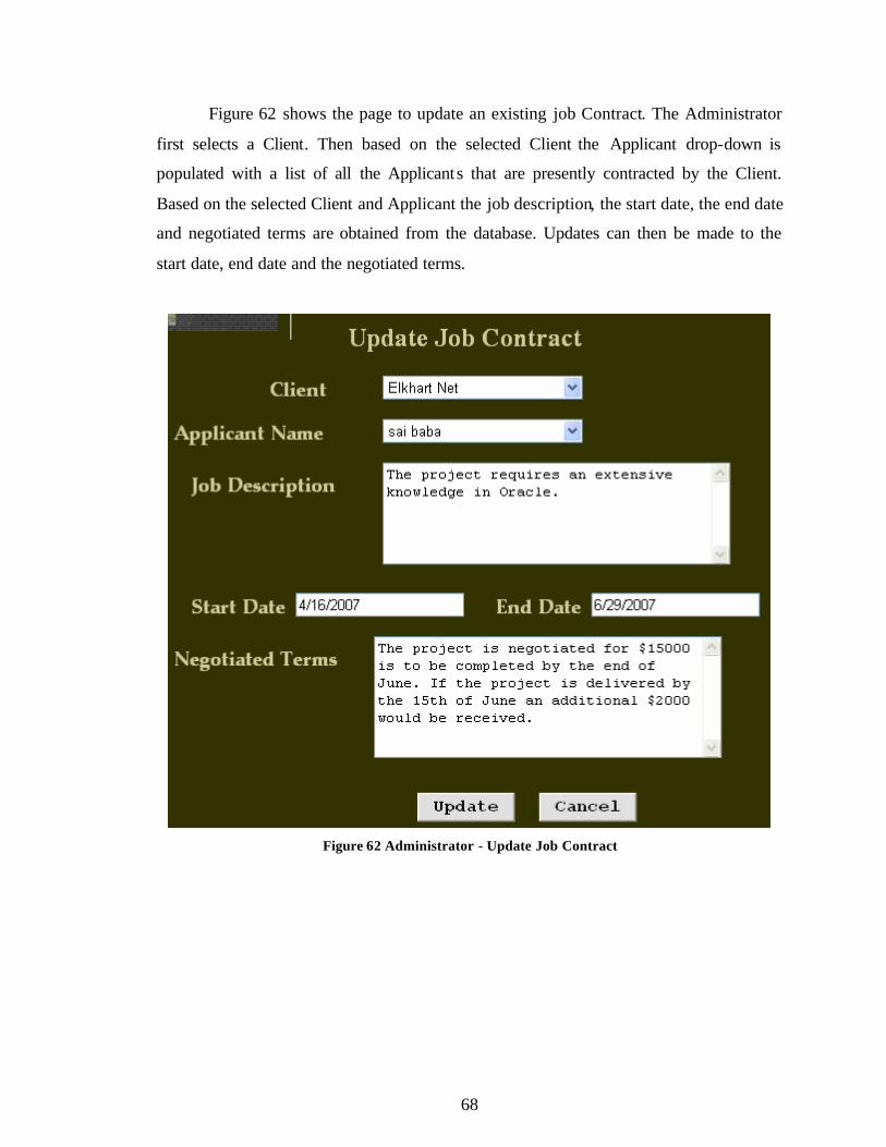
Figure 62 shows the page to update an existing job Contract. The Administrator
first selects a Client. Then based on the selected Client the Applicant drop-down is
populated with a list of all the Applicants that are presently contracted by the Client.
Based on the selected Client and Applicant the job description, the start date, the end date
and negotiated terms are obtained from the database. Updates can then be made to the
start date, end date and the negotiated terms.
Figure 62 Administrator - Update Job Contract
69
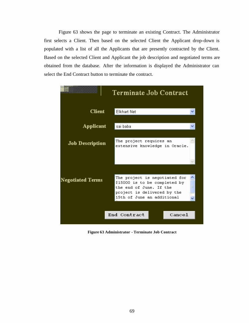
Figure 63 shows the page to terminate an existing Contract. The Administrator
first selects a Client. Then based on the selected Client the Applicant drop-down is
populated with a list of all the Applicants that are presently contracted by the Client.
Based on the selected Client and Applicant the job description and negotiated terms are
obtained from the database. After the information is displayed the Administrator can
select the End Contract button to terminate the contract.
Figure 63 Administrator - Terminate Job Contract
70
8. LIMITATIONS AND FUTURE DEVELOPMENT
There are some limitations for the current system to which solutions can be
provided as a future development:
• The system is designed for a software consulting firm and skills provided by the
firm are pre-defined. There is no user interface for adding new or editing existing
skills. A user interface can be developed as a future enhancement.
• At present the Applicant can only upload a Microsoft Word File for the resume.
This can be extended to include any other file types that are required.
• At present this product is run locally and cannot be accessed by everyone. It can
be deployed on a web server so that anyone connected to the Internet can access
it.
9. CONCLUSION
The consulting industry is one of the fastest growing business sectors worldwide
with new opportunities emerging in different fields including computer related services.
Software consulting and recruiting agencies match the requirements of the client firms
with the skills of their employees and set up the interview between their employees and
the client firm. Interviews are then conducted, and the candidates selected in the
interview are recruited as consultants in the client’s firm for the duration of the project.
Computer software engineers are projected to be one of the fastest-growing
occupations from 2004 to 2014. [6]. Consulting opportunities for computer software
engineers continue to grow as businesses seek help to manage, upgrade, and customize
their increasingly complicated computer systems.
This project implements a web-based software tool for human resource
management of a consulting firm that participates in the placement of consultants in
different organizations. The system is implemented using 3-tier architecture. To
71
implement this application the web server used is Microsoft IIS and the server side
technology used to create the web pages is ASP.NET. ASP.NET has several advantages
such as enhanced performance, scalability, built- in security and simplicity. Many
programming languages like VB.NET, C#, Java and J# are used to build ASP.NET web
applications. The programming language used to build this application is VB.NET.
ADO.NET is used to interact with the database. The database used to store the data is
MySQL database.
In the course of the implementation of this application many lessons have been
learned including designing an interface, database access technique and programming for
the web. This application helped in understanding the different technologies used to
create interactive web pages. It also helped in understanding the working of IIS and
ASP.NET. The implementation of the project has given a precise knowledge of how
ASP.NET is used to create web pages and how to connect to MySQL database using
ADO.NET. Overall the implementation of this project was an excellent learning
opportunity.
72
10. REFERENCES
Articles
1. Ang, S., & Slaughter, S. 1995. Alternative Employment Structure in Information
Systems: A Conceptual Analysis. In Proceedings of the 1995 ACM SIGCPR conference
on Supporting teams, groups, and learning inside and outside the IS function reinventing
IS, Nashville, United States, April 1995. ACM Press New York, NY, 181 - 193.
2. Joshi, J., Walid, A., & Ghafoor A. February 2001. Security models for web-based
applications, Communications of the ACM. Volume 44 Issue 2. ACM Press New York,
NY, 38 – 44.
3. Klaff, L. August 2003. A cure for contingent costs: companies that already use the
Web as a tool for product buying are now using it to manage contract workers, Workforce
Management .
4. Shepherd, G. November 2003. The ASP Column: ATL Server Versus ASP.NET, The
Microsoft Journal for Developers, MSDN Magazine.
5. U.S. Department of Labor, Summer 2000. An adapted excerpt from the U.S.
Department of Labor report Futurework: Trends and challenges for work in the 21st
century, Occupational Outlook Quaterly Online.
6. U.S. Department of Labor, 2006-07 Edition. Computer Software Engineers,
Occupational Outlook Handbook, 2006-07 Edition.
7. U.S. Department of Labor, 2006-07 Edition. Computer Systems Design and Related
Services, Career Guide to Industries (CGI).
Books
8. Goode, C. & Kauffman, J. Beginning ASP.NET 1.0 with Visual Basic.NET. Wrox Press
Limited.
9. King, T., Resse, G. & Yarger, R. Managing and Using MySQL. O.Reilly’s Publication
10. Meier, J.D., Mackman, A., Vasireddy, S., Dunner, M., Escamilla, R. & Murukan, A.
Improving Web Application Security: Threats and Countermeasures. Microsoft
Corporation.
73
Websites
11. http://www.brainbell.com/tutorials/ASP/ASP.NET_Application_Fundamentals.html
for ASP.NET worker process
12. http://www.cbizsoft.com for information on “cBizOne”
13. http://www.evalica.com/cm/products/r_tech/a_recruiter for information on “Attract
Recruiter”
14. http://www.pcrecruiter.com for information on “PCRecruiter”.
15. http://www.microsoft.com/windowsxp/evaluation/features/iis.mspx for IIS 5.1
16. http://msdn2.microsoft.com/en-us/library/27y4ybxw.aspx for DataSet Vs DataReader
74
11. BIBLIOGRAPHY
Articles
1. Aldhizer, G. & Turner, L. March 2003. How to pick a consulting firm, Strategic
Finance.
2. Andrews, A. & Niederman, F. 1998. A Firm-Level Model of IT Personnel Planning.
In Proceedings of the 1998 ACM SIGCPR conference on computer personal research,
Boston, United States, June 1998.
Books
4 Hoyt, D. “Start and run a successful independent consulting business”.
5. George Resse, Randy Jay Yarger & Tim King with Hugh E. Willams, “Managing &
Using MySQL”, second edition, published by O’Reilly & Associates Inc.
6. Mathew MacDonald, “ASP.NET: Complete-Reference”
7. Shelly, Cashman & Adamski “Systems Analysis and Design”, second edition, Boyd &
Fraser publishing company.
Websites
8. http://www.crlab.com/mysqlnet/ for ado.net data provider
9. http://msdn2.microsoft.com/en-us/library/27y4ybxw.aspx for the architecture of
ado.net
10. http://msdn2.microsoft.com/en-us/library/aa302436.aspx for the architecture of
asp.net
Recommended