NOE – The Formwork
Assembly and Operating ManualDated 03.2010

2 Dated 03.2010 AuV NOElight Subject to technical modifications.
Subject to technical modifications. AuV NOElight Dated 03.2010 3
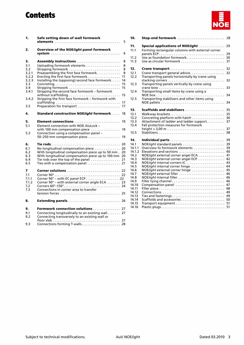
Contents
1. Safesettingdownofwallformworkelements . . . . . . . . . . . . . . . . . . . . . . . . . . . . . . . . . . . . 5
2. OverviewoftheNOEIightpanelformworksystem . . . . . . . . . . . . . . . . . . . . . . . . . . . . . . . . . . . . . . 6
3. Assemblyinstructions . . . . . . . . . . . . . . . . . . . . . . . . 83.1 Uploading formwork elements . . . . . . . . . . . . . . . . . . . 83.2 Stripping formwork . . . . . . . . . . . . . . . . . . . . . . . . . . . . 83.2.1 Preassembling the first face formwork . . . . . . . . . . . . . 83.2.2 Erecting the first face formwork . . . . . . . . . . . . . . . . . . 113.2.3 Installing the (opposing) second face formwork . . . . . 143.3 Concreting . . . . . . . . . . . . . . . . . . . . . . . . . . . . . . . . . . . . 153.4 Stripping formwork . . . . . . . . . . . . . . . . . . . . . . . . . . . . 153.4.1 Stripping the second face formwork – formwork
without scaffolding . . . . . . . . . . . . . . . . . . . . . . . . . . . . 153.4.2 Stripping the first face formwork – formwork with
scaffolding . . . . . . . . . . . . . . . . . . . . . . . . . . . . . . . . . . . 173.5 Preparation for transport . . . . . . . . . . . . . . . . . . . . . . . 17
4. StandardconstructionNOEIightformwork . . . . . 18
5. Elementconnections . . . . . . . . . . . . . . . . . . . . . . . . . 195.1 Element connection with NOE AluLock –
with 100 mm compensation piece . . . . . . . . . . . . . . . . 195.2 Connection using a compensation panel –
50–250 mm compensation piece . . . . . . . . . . . . . . . . . . 19
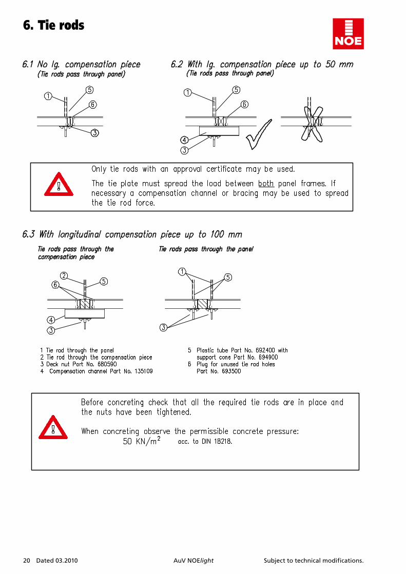
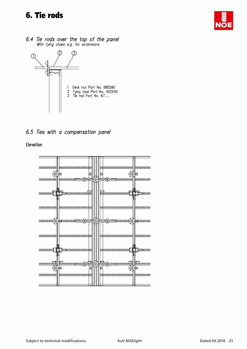
6. Tierods . . . . . . . . . . . . . . . . . . . . . . . . . . . . . . . . . . . . . . 206.1 No longitudinal compensation piece . . . . . . . . . . . . . . 206.2 With longitudinal compensation piece up to 50 mm . 206.3 With longitudinal compensation piece up to 100 mm 206.4 Tie rods over the top of the panel . . . . . . . . . . . . . . . . 216.5 Ties with a compensation panel . . . . . . . . . . . . . . . . . . 21
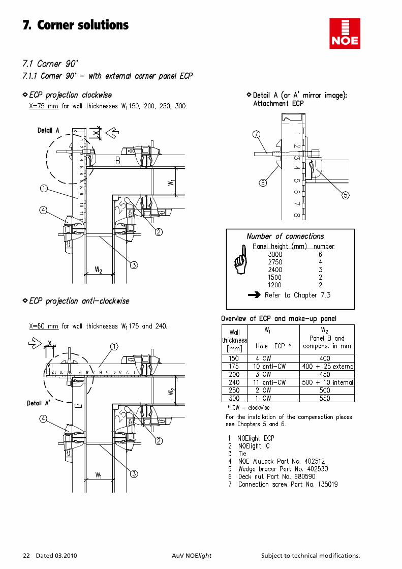
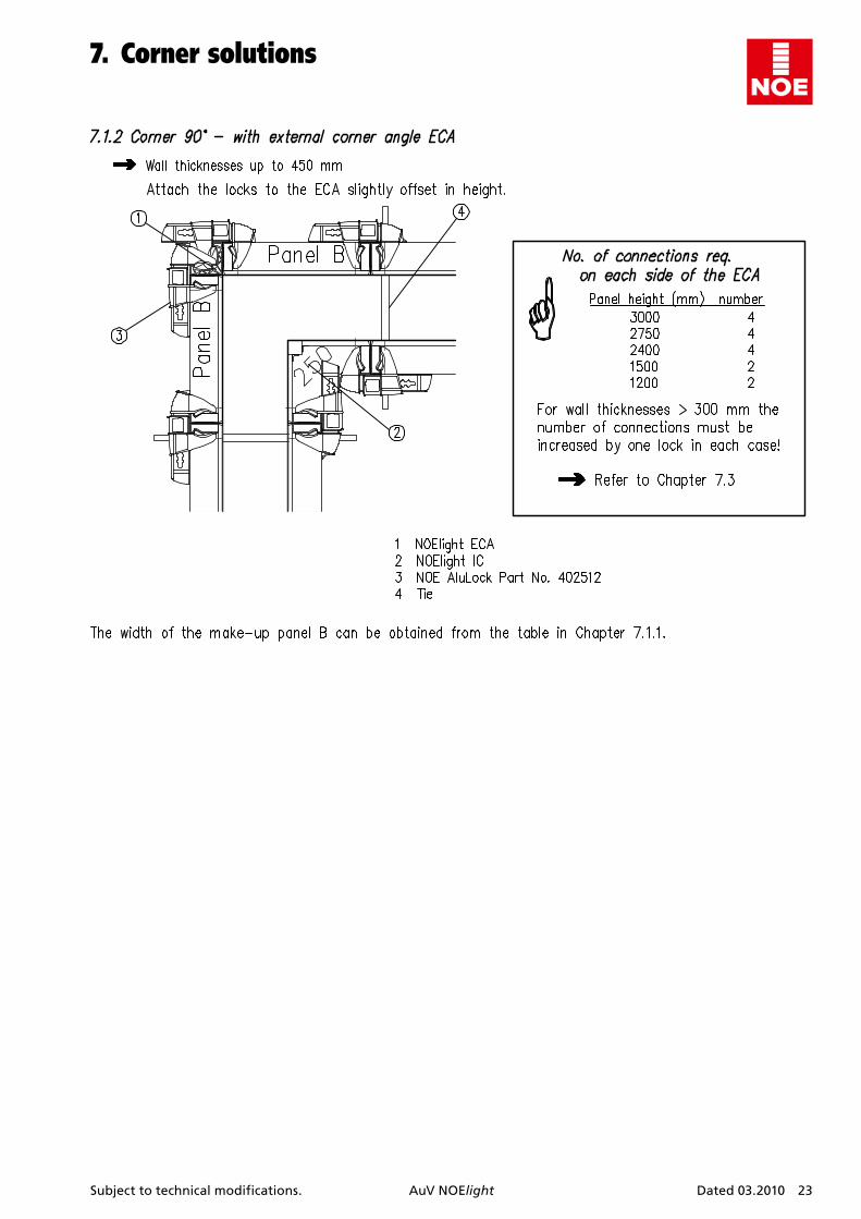
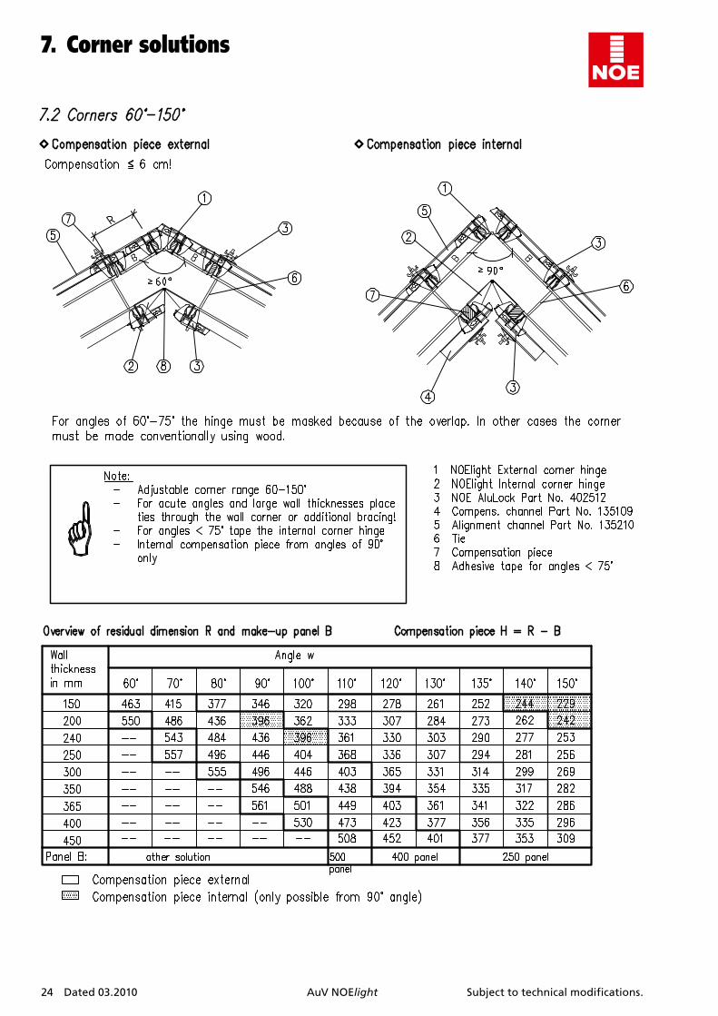
7 Cornersolutions . . . . . . . . . . . . . . . . . . . . . . . . . . . . . 227.1 Corner 90° . . . . . . . . . . . . . . . . . . . . . . . . . . . . . . . . . . . . 227.1.1 Corner 90° – with EC panel ECP . . . . . . . . . . . . . . . . . . . 227.1.2 Corner 90° – with external corner angle ECA . . . . . . . 237.2 Corners 60°–150° . . . . . . . . . . . . . . . . . . . . . . . . . . . . . . . 247.3 Connections in corner area to transfer
tension forces . . . . . . . . . . . . . . . . . . . . . . . . . . . . . . . . . 25
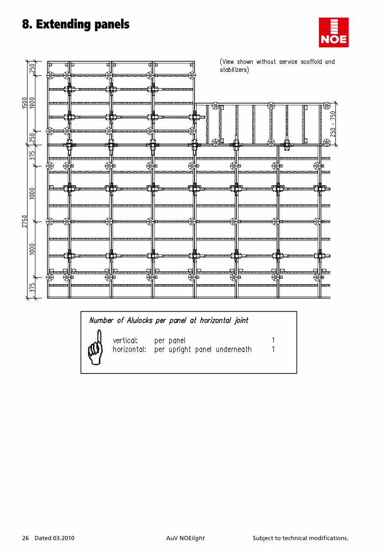
8. Extendingpanels . . . . . . . . . . . . . . . . . . . . . . . . . . . . . 26
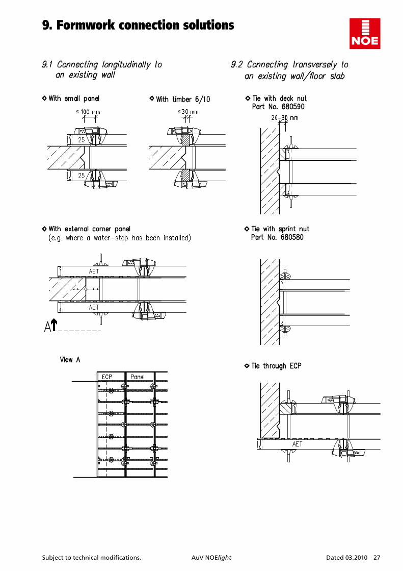
9. Formworkconnectionsolutions . . . . . . . . . . . . . . . 279.1 Connecting longitudinally to an existing wall . . . . . . . 279.2 Connecting transversely to an existing wall or
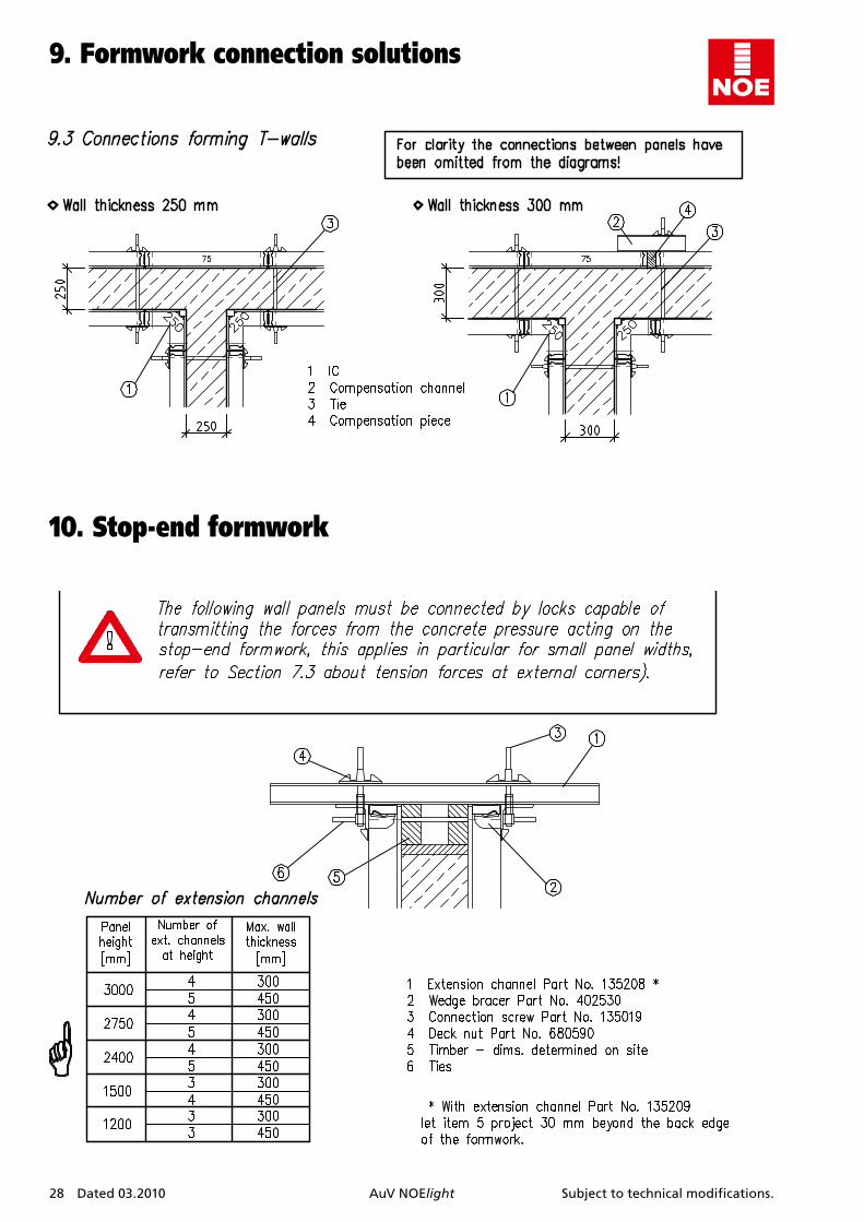
floor slab . . . . . . . . . . . . . . . . . . . . . . . . . . . . . . . . . . . . . 279.3 Connections forming T-walls . . . . . . . . . . . . . . . . . . . . . 28
10. Stop-endformwork . . . . . . . . . . . . . . . . . . . . . . . . . . 28
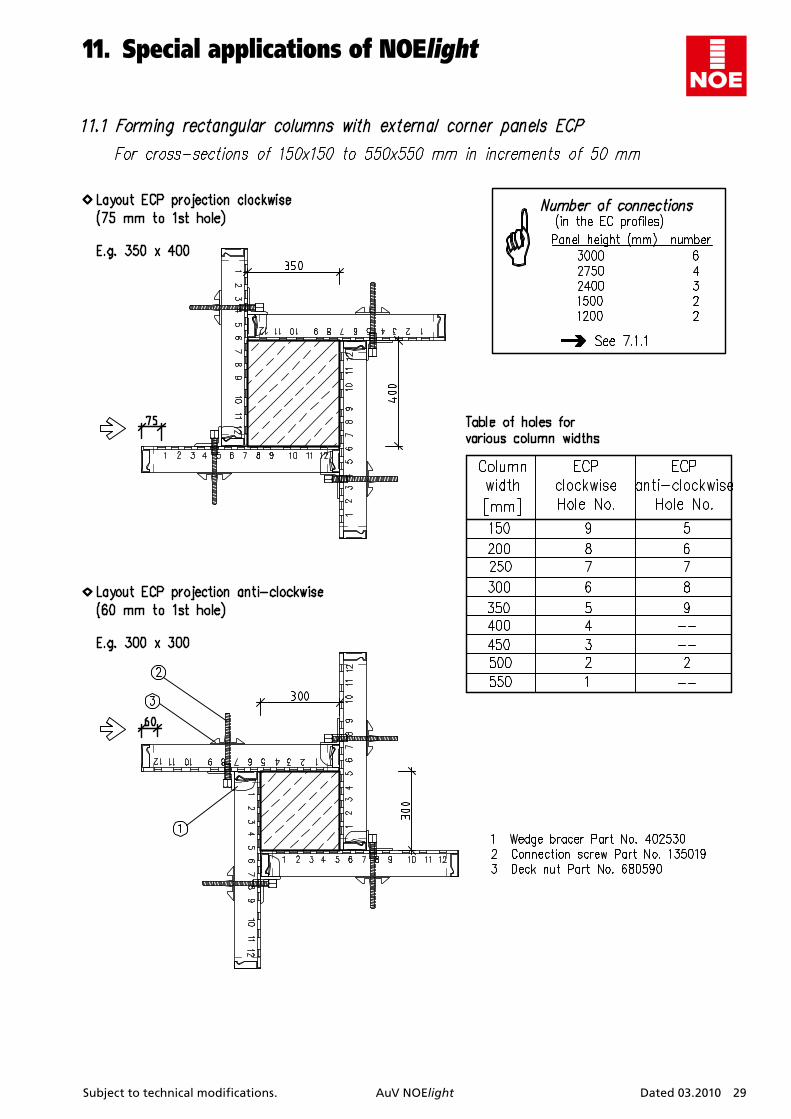
11. SpecialapplicationsofNOEIight . . . . . . . . . . . . . . . 2911.1 Forming rectangular columns with external corner
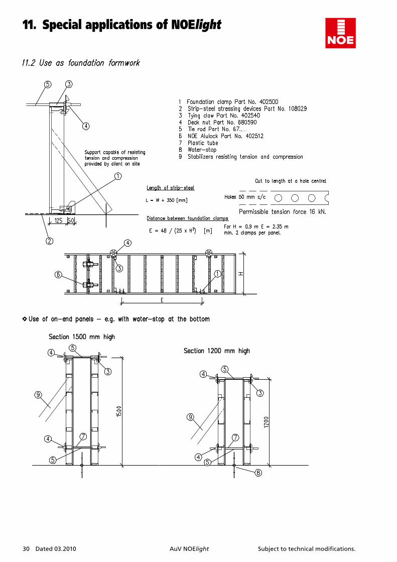
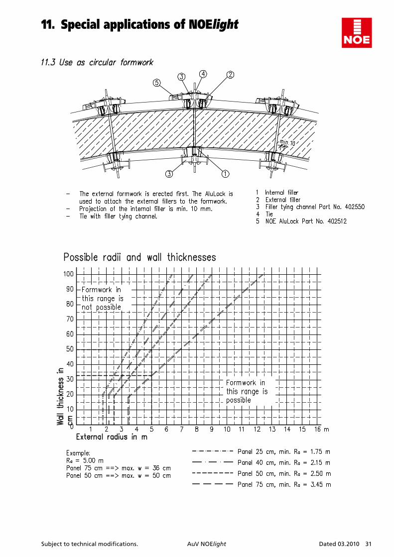
panels ECP . . . . . . . . . . . . . . . . . . . . . . . . . . . . . . . . . . . . 2911.2 Use as foundation formwork . . . . . . . . . . . . . . . . . . . . . 3011.3 Use as circular formwork . . . . . . . . . . . . . . . . . . . . . . . . 31
12. Cranetransport . . . . . . . . . . . . . . . . . . . . . . . . . . . . . . 3212.1 Crane transport general advice . . . . . . . . . . . . . . . . . . . 3212.2 Transporting panels horizontally by crane using
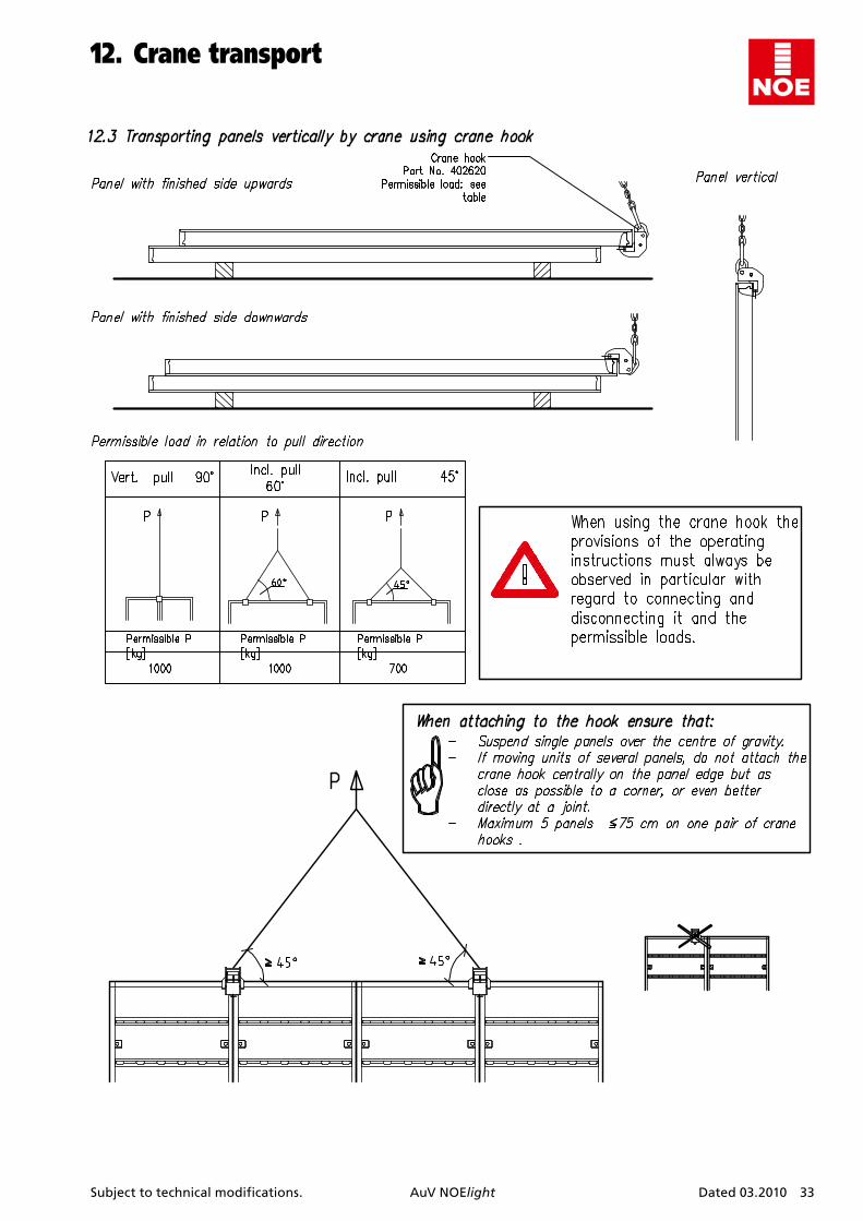
stacking corners . . . . . . . . . . . . . . . . . . . . . . . . . . . . . . . 3212.3 Transporting panels vertically by crane using
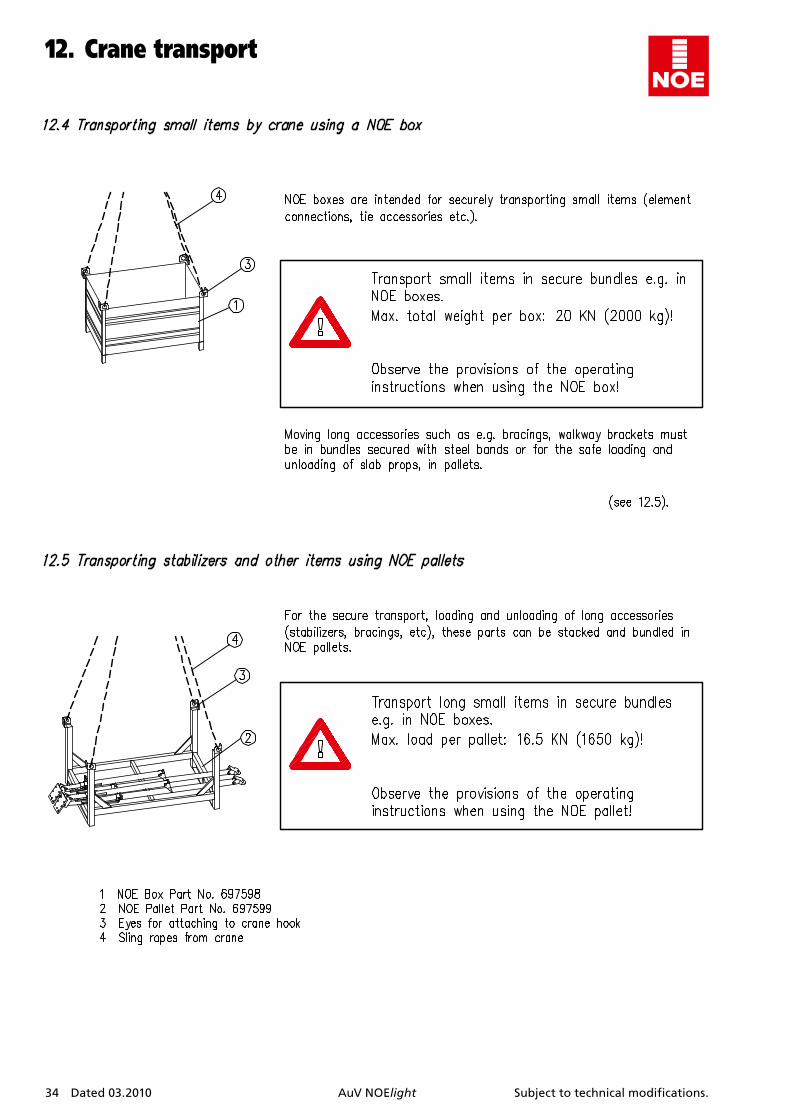
crane bow . . . . . . . . . . . . . . . . . . . . . . . . . . . . . . . . . . . . 3312.4 Transporting small items by crane using a
NOE box . . . . . . . . . . . . . . . . . . . . . . . . . . . . . . . . . . . . . . 3412.5 Transporting stabilizers and other items using
NOE pallets . . . . . . . . . . . . . . . . . . . . . . . . . . . . . . . . . . . 34
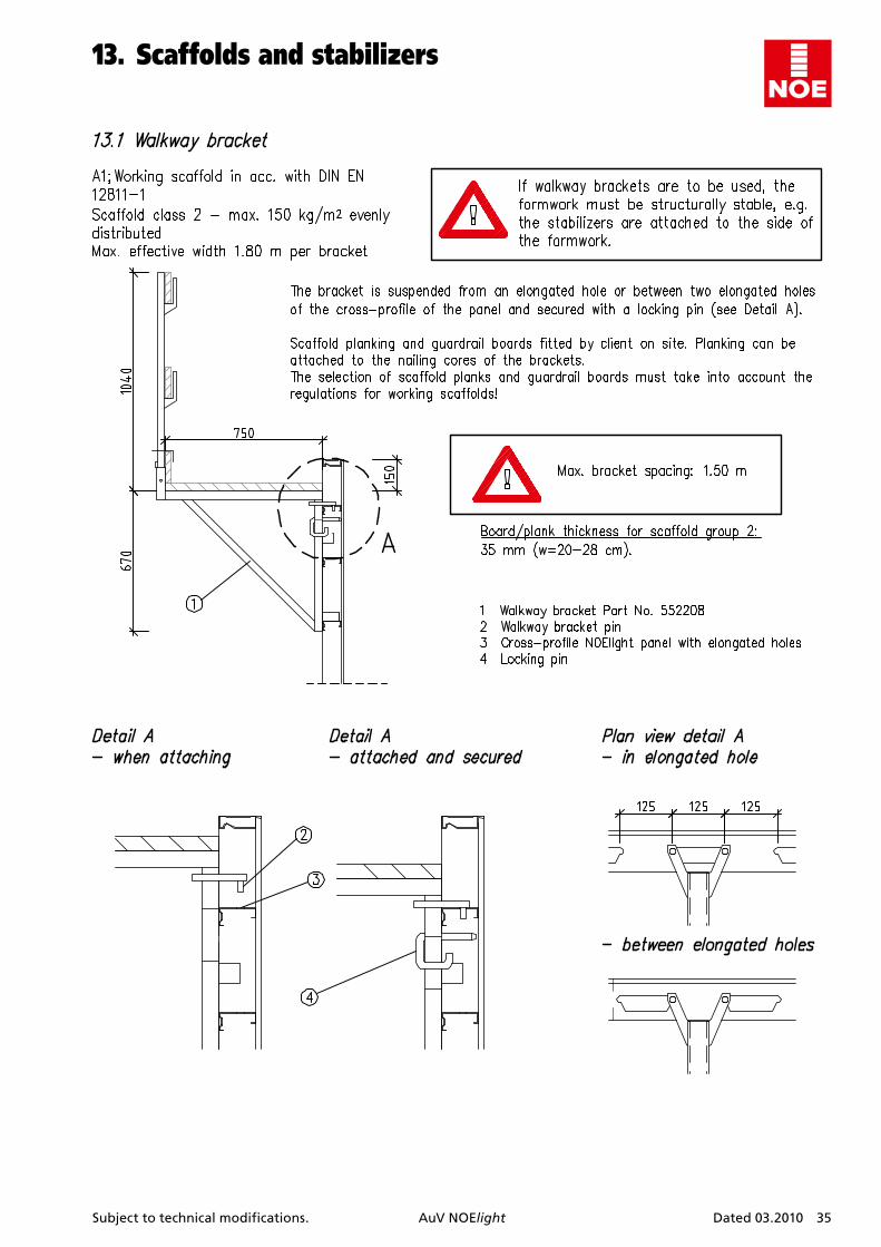
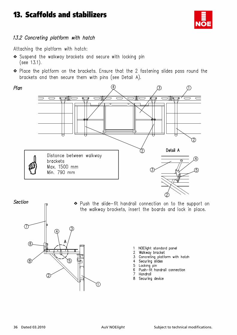
13. Scaffoldsandstabilizers . . . . . . . . . . . . . . . . . . . . . . 3513.1 Walkway brackets . . . . . . . . . . . . . . . . . . . . . . . . . . . . . . 3513.2 Concreting platform with hatch . . . . . . . . . . . . . . . . . . 3613.3 Attachment of ladder and ladder support . . . . . . . . . . 3713.4 Fall protection measures for formwork
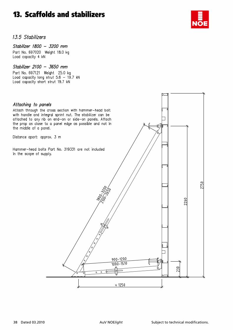
height > 3,00 m . . . . . . . . . . . . . . . . . . . . . . . . . . . . . . . . 3713.5 Stabilizers. . . . . . . . . . . . . . . . . . . . . . . . . . . . . . . . . . . . . 38
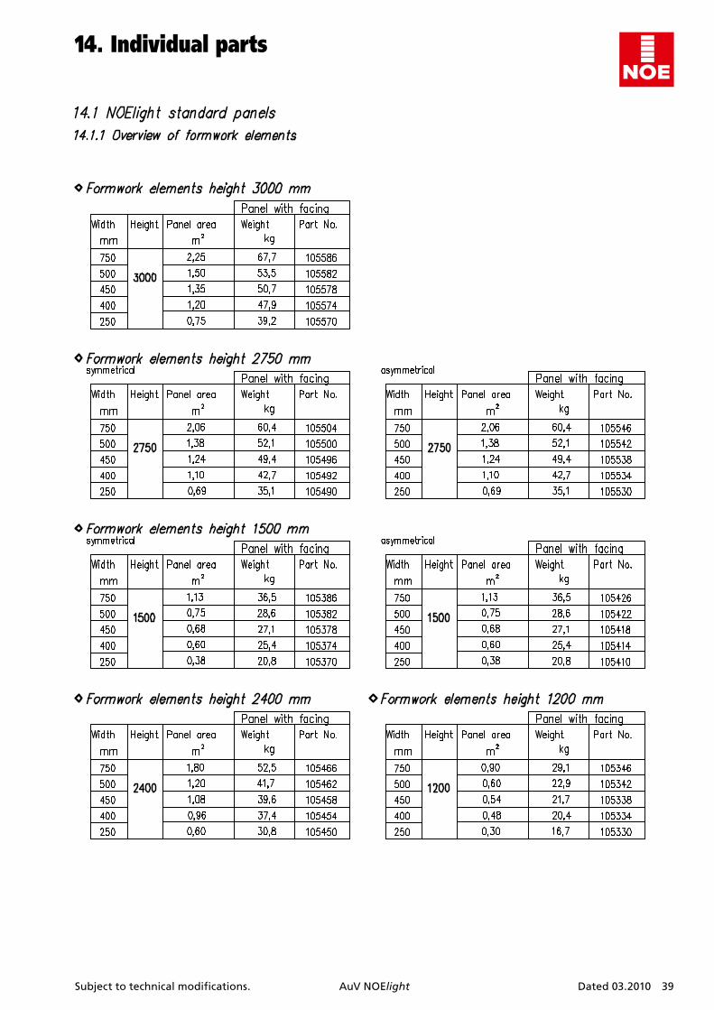
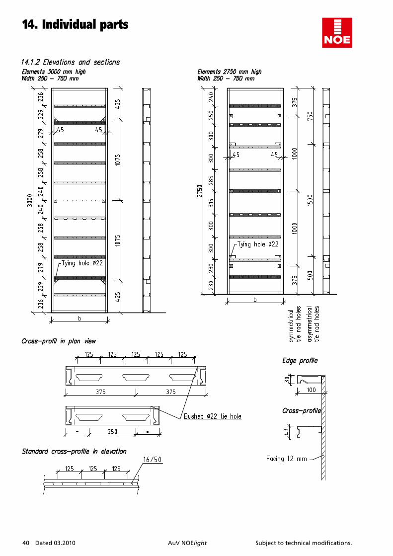
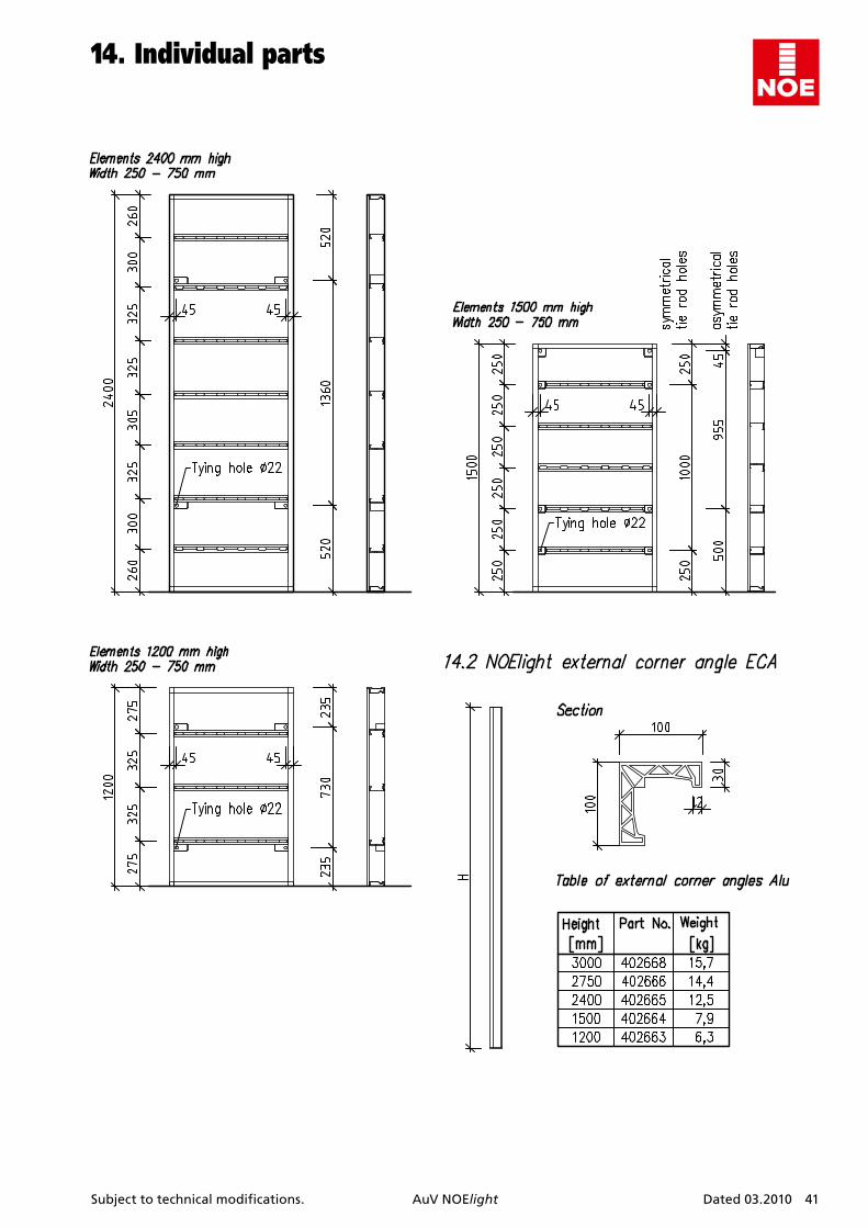
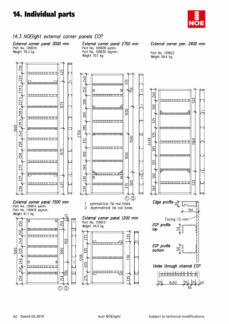
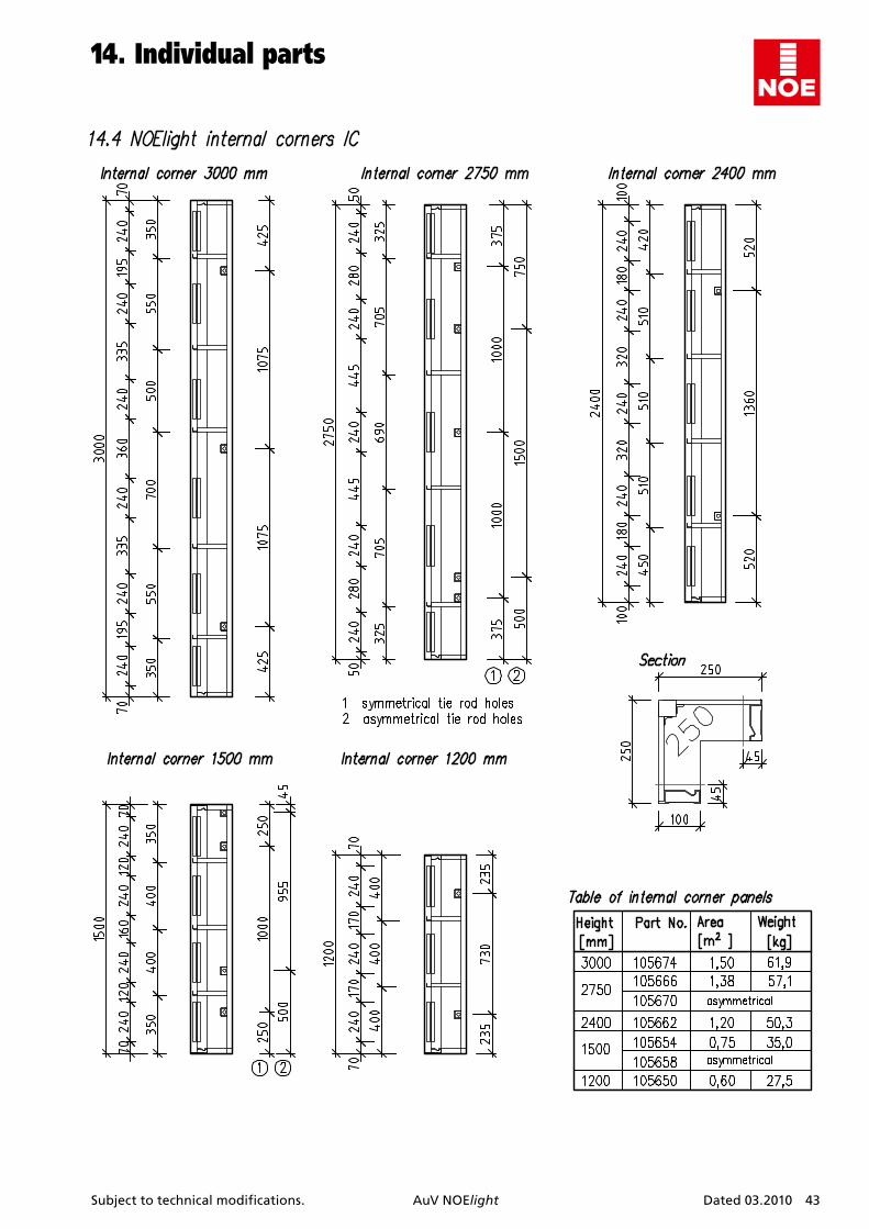
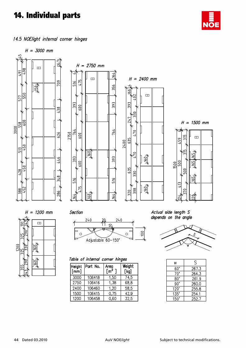
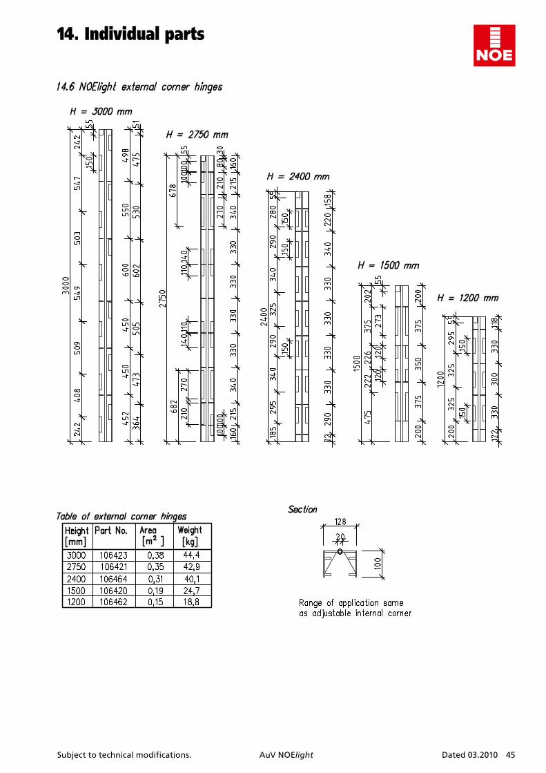
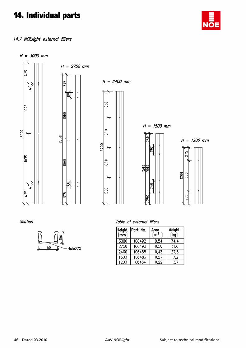
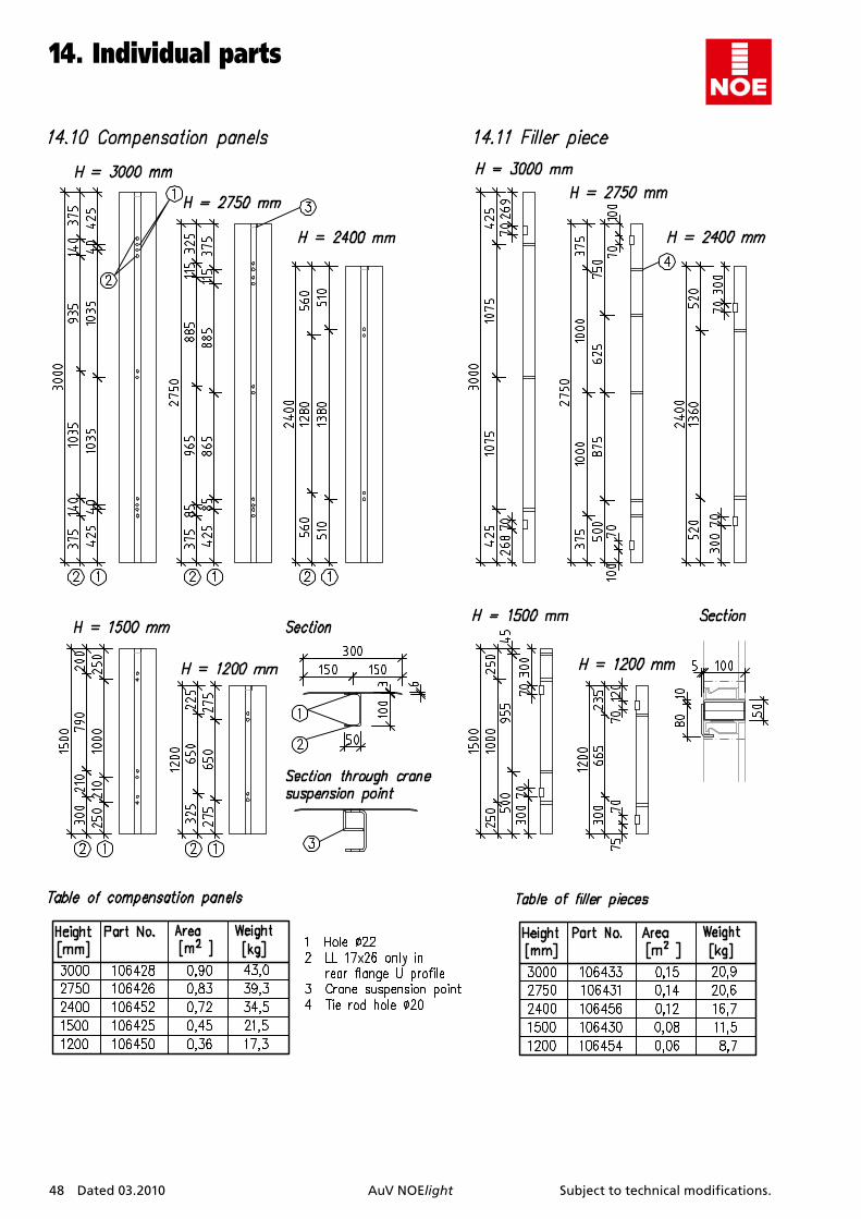
14. Individualparts . . . . . . . . . . . . . . . . . . . . . . . . . . . . . . 3914.1 NOEIight standard panels . . . . . . . . . . . . . . . . . . . . . . . 3914.1.1 Overview fo formwork elements . . . . . . . . . . . . . . . . . 3914.1.2 Elevations and sections . . . . . . . . . . . . . . . . . . . . . . . . . 4014.2 NOEIight external corner angel ECA . . . . . . . . . . . . . . . 4114.3 NOEIight external corner angel ECP . . . . . . . . . . . . . . . 4214.4 NOEIight internal corners IC . . . . . . . . . . . . . . . . . . . . . 4314.5 NOEIight internal corner hinge . . . . . . . . . . . . . . . . . . . 4414.6 NOEIight external corner hinge . . . . . . . . . . . . . . . . . . 4514.7 NOEIight external filler . . . . . . . . . . . . . . . . . . . . . . . . . 4614.8 NOEIight internal filler . . . . . . . . . . . . . . . . . . . . . . . . . . 4614.9 Filler tying channel . . . . . . . . . . . . . . . . . . . . . . . . . . . . . 4614.10 Compensation panel . . . . . . . . . . . . . . . . . . . . . . . . . . . 4714.11 Filler piece . . . . . . . . . . . . . . . . . . . . . . . . . . . . . . . . . . . . 4814.12 Connections . . . . . . . . . . . . . . . . . . . . . . . . . . . . . . . . . . . 4914.13 Ties and fastenings . . . . . . . . . . . . . . . . . . . . . . . . . . . . . 4914.14 Scaffolds and accessories . . . . . . . . . . . . . . . . . . . . . . . . 5014.15 Transport equipment . . . . . . . . . . . . . . . . . . . . . . . . . . . 5114.16 Plastic plugs . . . . . . . . . . . . . . . . . . . . . . . . . . . . . . . . . . . 51
4 Dated 03.2010 AuV NOElight Subject to technical modifications.
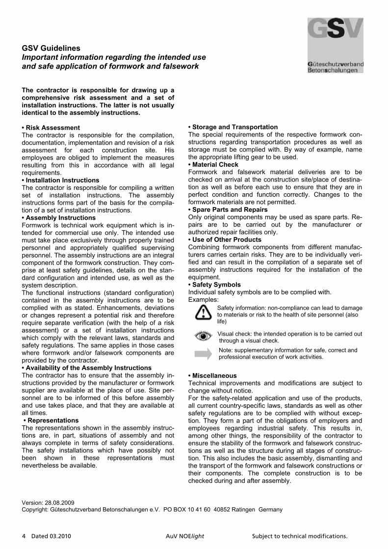
GSV Guidelines Important information regarding the intended useand safe application of formwork and falsework
The contractor is responsible for drawing up a comprehensive risk assessment and a set of installation instructions. The latter is not usually identical to the assembly instructions.
• Risk Assessment The contractor is responsible for the compilation, documentation, implementation and revision of a risk assessment for each construction site. His employees are obliged to implement the measures resulting from this in accordance with all legal requirements.• Installation Instructions The contractor is responsible for compiling a written set of installation instructions. The assembly instructions forms part of the basis for the compila-tion of a set of installation instructions. • Assembly Instructions Formwork is technical work equipment which is in-tended for commercial use only. The intended use must take place exclusively through properly trained personnel and appropriately qualified supervising personnel. The assembly instructions are an integral component of the formwork construction. They com-prise at least safety guidelines, details on the stan-dard configuration and intended use, as well as the system description. The functional instructions (standard configuration) contained in the assembly instructions are to be complied with as stated. Enhancements, deviations or changes represent a potential risk and therefore require separate verification (with the help of a risk assessment) or a set of installation instructions which comply with the relevant laws, standards and safety regulations. The same applies in those cases where formwork and/or falsework components are provided by the contractor. • Availability of the Assembly Instructions The contractor has to ensure that the assembly in-structions provided by the manufacturer or formwork supplier are available at the place of use. Site per-sonnel are to be informed of this before assembly and use takes place, and that they are available at all times. • Representations The representations shown in the assembly instruc-tions are, in part, situations of assembly and not always complete in terms of safety considerations. The safety installations which have possibly not been shown in these representations must nevertheless be available.
• Storage and TransportationThe special requirements of the respective formwork con-structions regarding transportation procedures as well as storage must be complied with. By way of example, name the appropriate lifting gear to be used. • Material Check Formwork and falsework material deliveries are to be checked on arrival at the construction site/place of destina-tion as well as before each use to ensure that they are in perfect condition and function correctly. Changes to the formwork materials are not permitted. • Spare Parts and Repairs Only original components may be used as spare parts. Re-pairs are to be carried out by the manufacturer or authorized repair facilities only. • Use of Other Products Combining formwork components from different manufac-turers carries certain risks. They are to be individually veri-fied and can result in the compilation of a separate set of assembly instructions required for the installation of the equipment. • Safety Symbols Individual safety symbols are to be complied with. Examples:
• Miscellaneous Technical improvements and modifications are subject to change without notice. For the safety-related application and use of the products, all current country-specific laws, standards as well as other safety regulations are to be complied with without excep-tion. They form a part of the obligations of employers and employees regarding industrial safety. This results in, among other things, the responsibility of the contractor to ensure the stability of the formwork and falsework construc-tions as well as the structure during all stages of construc-tion. This also includes the basic assembly, dismantling and the transport of the formwork and falsework constructions or their components. The complete construction is to be checked during and after assembly.
Version: 28.08.2009 Copyright: Güteschutzverband Betonschalungen e.V. PO BOX 10 41 60 40852 Ratingen Germany
Visual check: the intended operation is to be carried out through a visual check. Note: supplementary information for safe, correct and professional execution of work activities.
Safety information: non-compliance can lead to damage to materials or risk to the health of site personnel (also life)
Subject to technical modifications. AuV NOElight Dated 03.2010 5
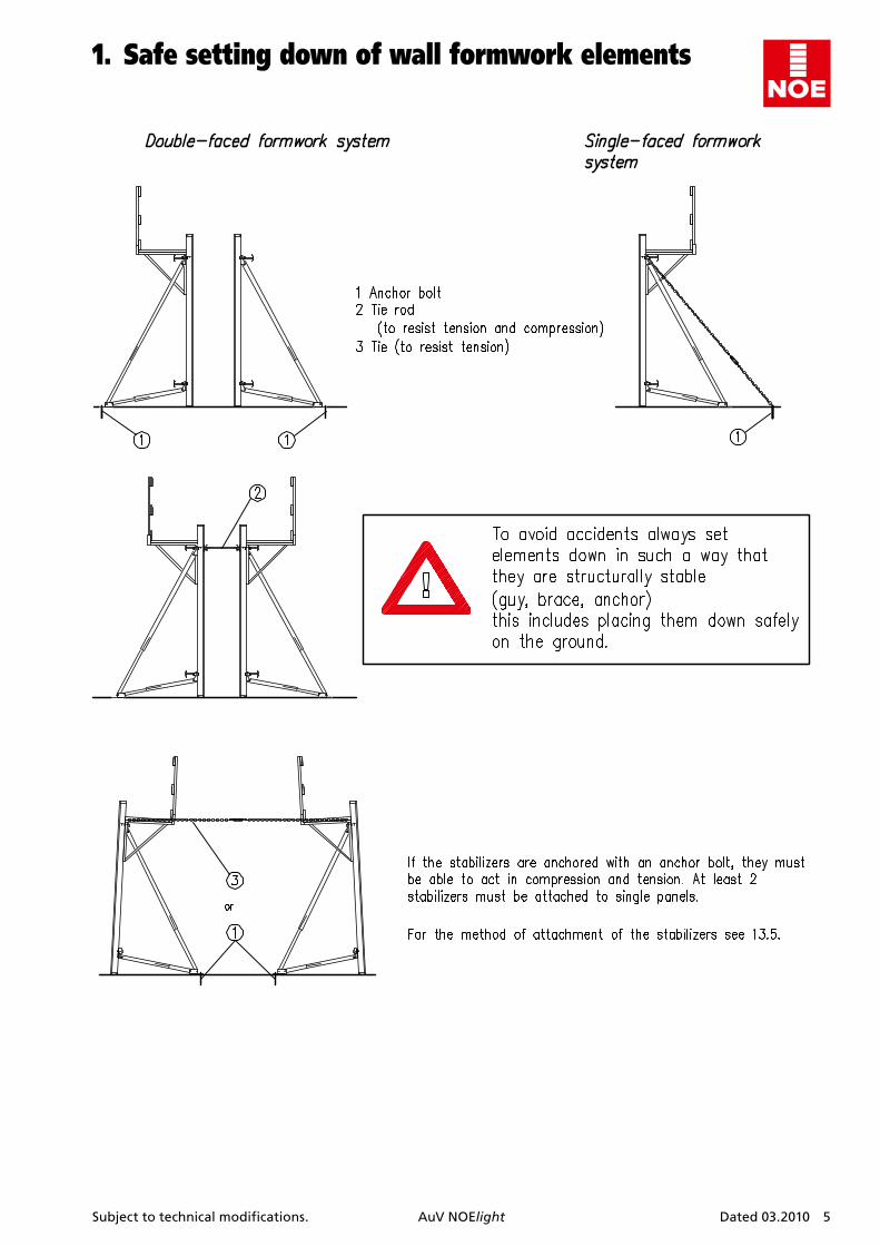
1. Safesettingdownofwallformworkelements
6 Dated 03.2010 AuV NOElight Subject to technical modifications.
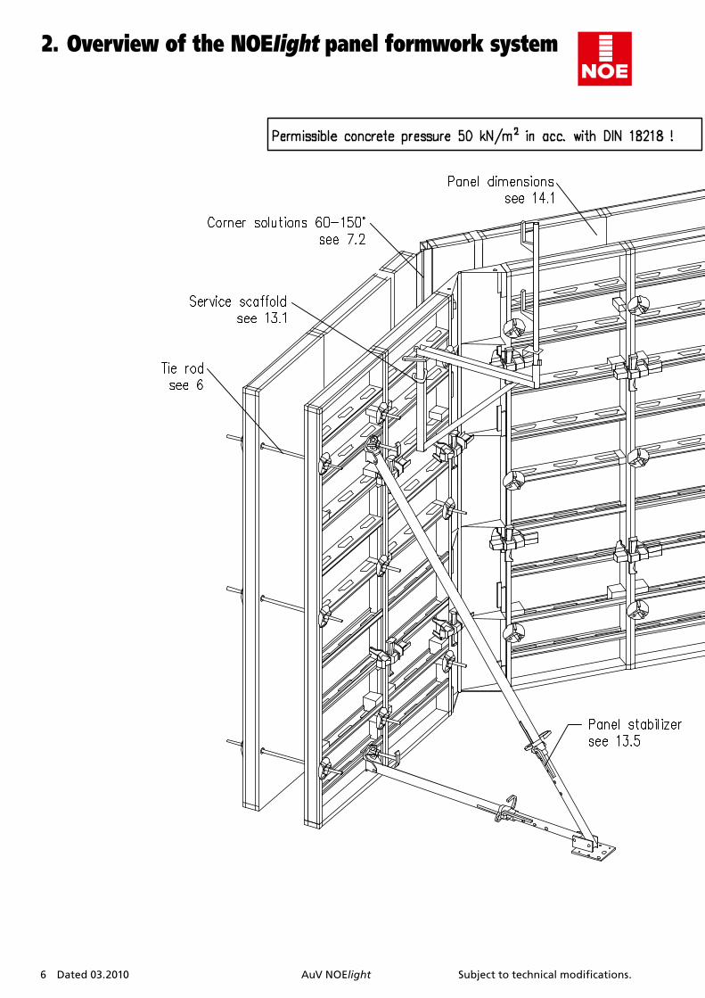
2.OverviewoftheNOEIightpanelformworksystem
Subject to technical modifications. AuV NOElight Dated 03.2010 7
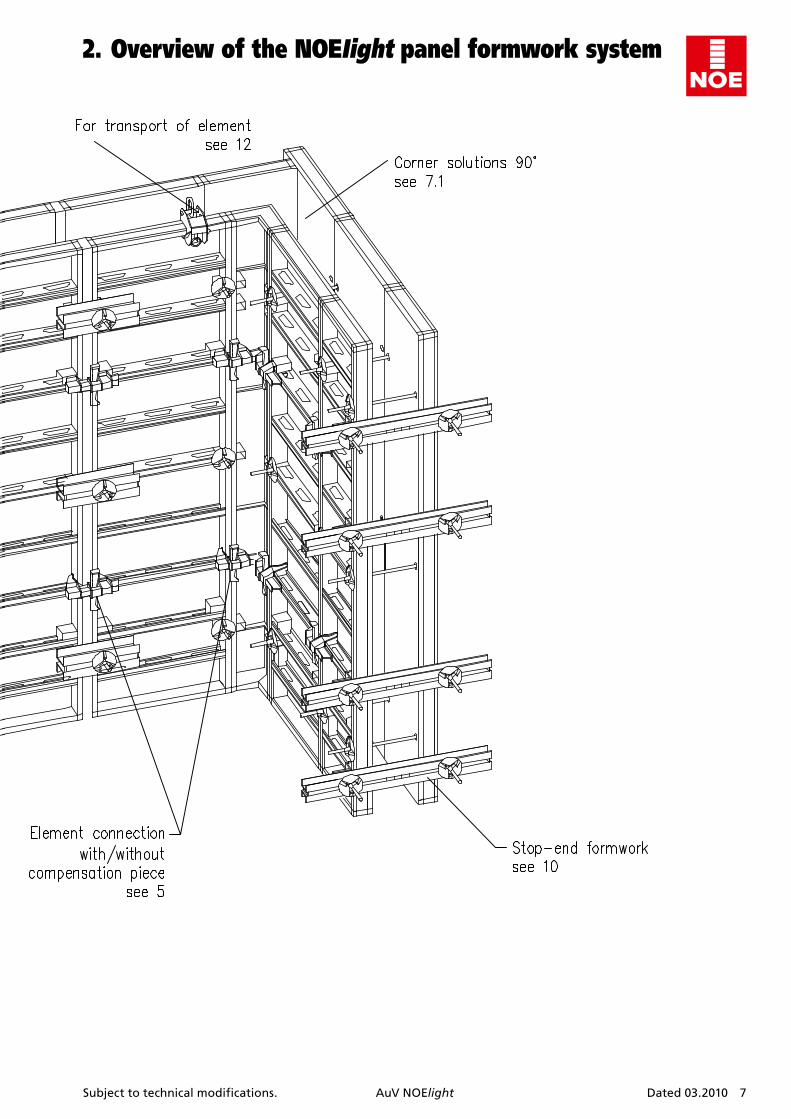
2.OverviewoftheNOEIightpanelformworksystem

8 Dated 03.2010 AuV NOElight Subject to technical modifications.
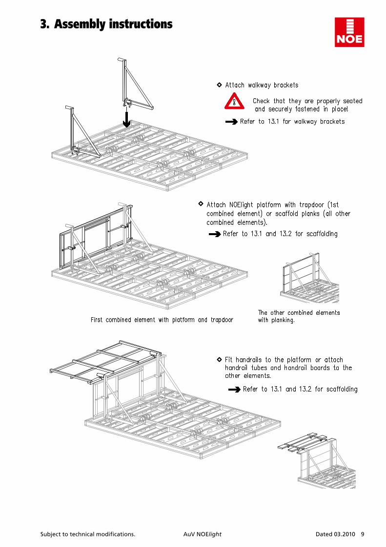
3.Assemblyinstructions
Subject to technical modifications. AuV NOElight Dated 03.2010 9
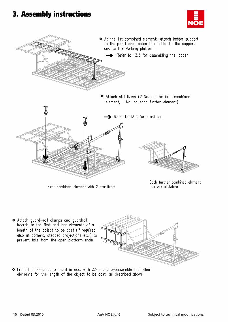
3.Assemblyinstructions
10 Dated 03.2010 AuV NOElight Subject to technical modifications.
3.Assemblyinstructions
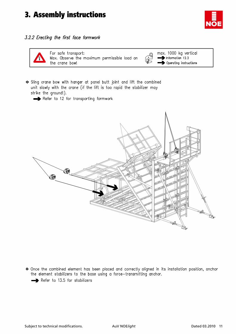
Subject to technical modifications. AuV NOElight Dated 03.2010 11
3.Assemblyinstructions
12 Dated 03.2010 AuV NOElight Subject to technical modifications.
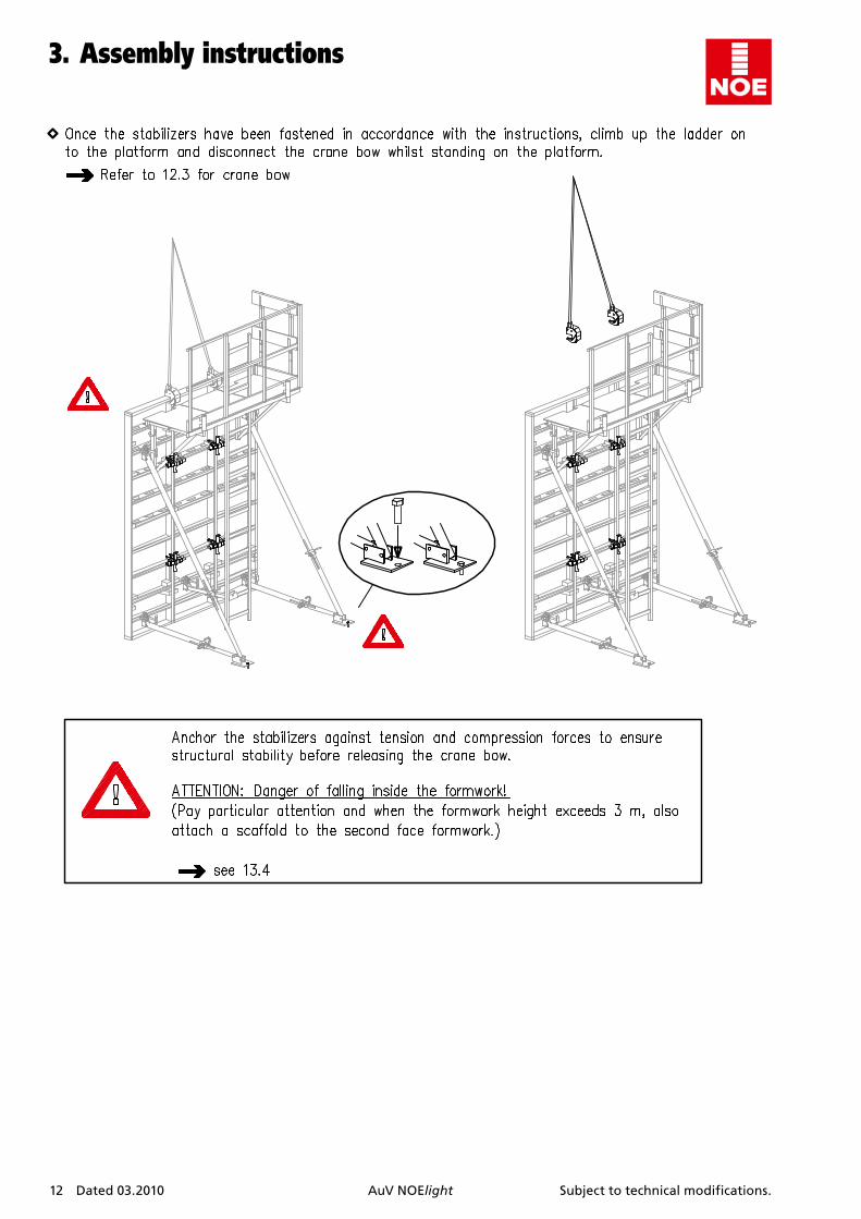
3.Assemblyinstructions
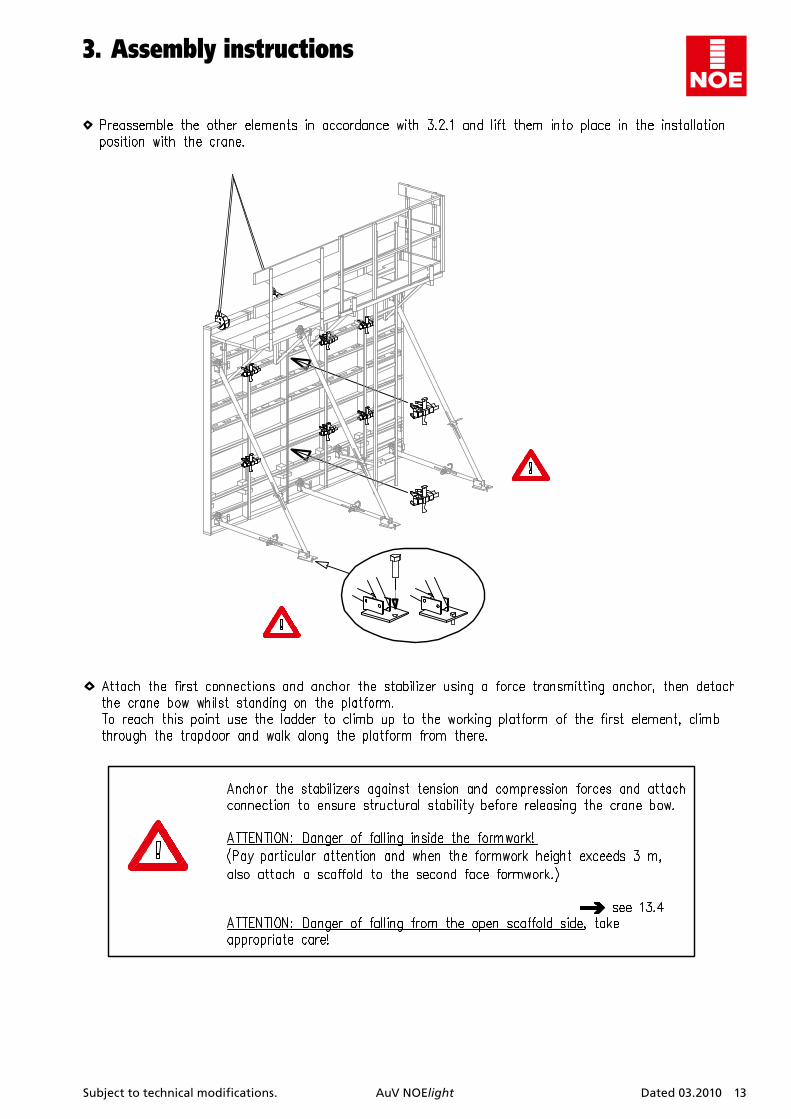
Subject to technical modifications. AuV NOElight Dated 03.2010 13
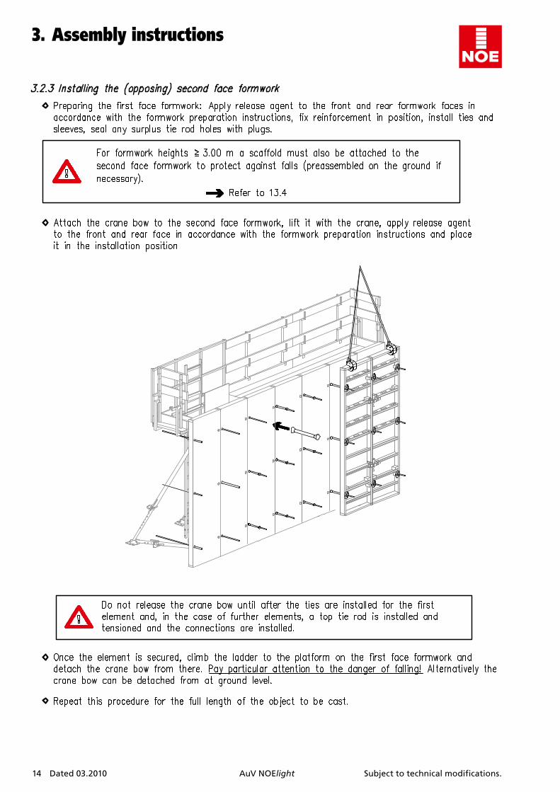
3.Assemblyinstructions
14 Dated 03.2010 AuV NOElight Subject to technical modifications.
3.Assemblyinstructions
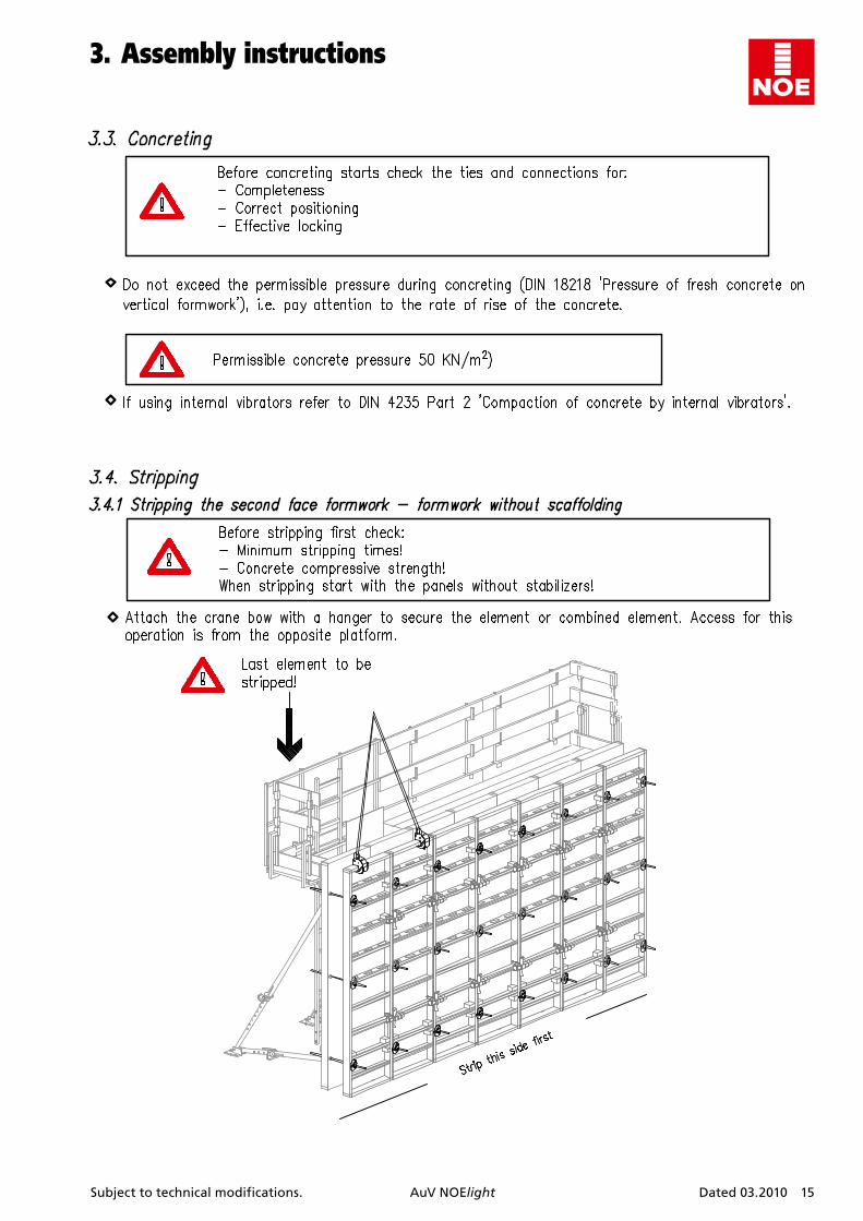
Subject to technical modifications. AuV NOElight Dated 03.2010 15
3.Assemblyinstructions

16 Dated 03.2010 AuV NOElight Subject to technical modifications.
3.Assemblyinstructions
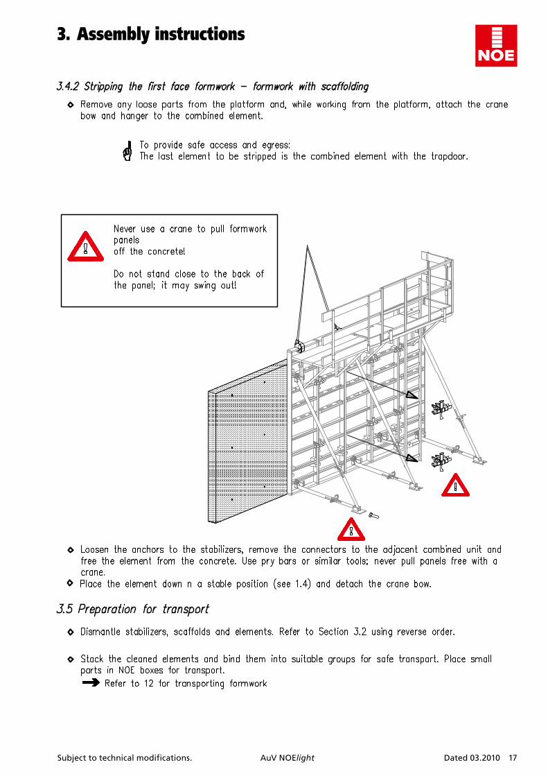
Subject to technical modifications. AuV NOElight Dated 03.2010 17
3.Assemblyinstructions
18 Dated 03.2010 AuV NOElight Subject to technical modifications.
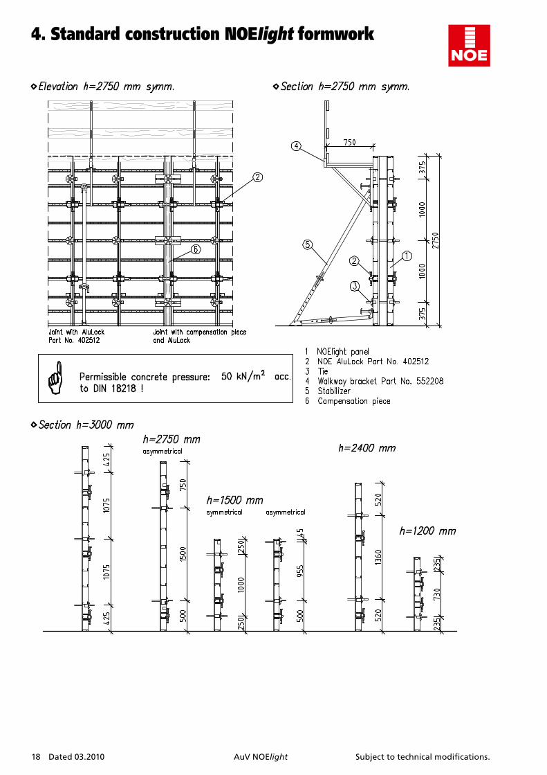
4.StandardconstructionNOEIightformwork
Subject to technical modifications. AuV NOElight Dated 03.2010 19
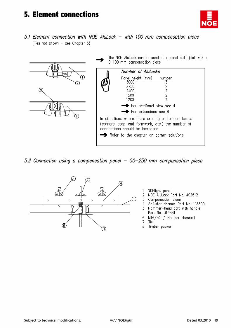
5.Elementconnections
20 Dated 03.2010 AuV NOElight Subject to technical modifications.
6.Tierods
Subject to technical modifications. AuV NOElight Dated 03.2010 21
6.Tierods
22 Dated 03.2010 AuV NOElight Subject to technical modifications.
7. Cornersolutions
Subject to technical modifications. AuV NOElight Dated 03.2010 23
7. Cornersolutions
24 Dated 03.2010 AuV NOElight Subject to technical modifications.
7. Cornersolutions

Subject to technical modifications. AuV NOElight Dated 03.2010 25
7. Cornersolutions
26 Dated 03.2010 AuV NOElight Subject to technical modifications.
8.Extendingpanels
Subject to technical modifications. AuV NOElight Dated 03.2010 27
9.Formworkconnectionsolutions
28 Dated 03.2010 AuV NOElight Subject to technical modifications.
9.Formworkconnectionsolutions
10.Stop-endformwork
Subject to technical modifications. AuV NOElight Dated 03.2010 29
11. SpecialapplicationsofNOElight
30 Dated 03.2010 AuV NOElight Subject to technical modifications.
11. SpecialapplicationsofNOElight
Subject to technical modifications. AuV NOElight Dated 03.2010 31
11. SpecialapplicationsofNOElight

32 Dated 03.2010 AuV NOElight Subject to technical modifications.
12.Cranetransport
Subject to technical modifications. AuV NOElight Dated 03.2010 33
12.Cranetransport
34 Dated 03.2010 AuV NOElight Subject to technical modifications.
12.Cranetransport
Subject to technical modifications. AuV NOElight Dated 03.2010 35
13.Scaffoldsandstabilizers
36 Dated 03.2010 AuV NOElight Subject to technical modifications.
13.Scaffoldsandstabilizers

Subject to technical modifications. AuV NOElight Dated 03.2010 37
13.Scaffoldsandstabilizers
38 Dated 03.2010 AuV NOElight Subject to technical modifications.
13.Scaffoldsandstabilizers
Subject to technical modifications. AuV NOElight Dated 03.2010 39
14.Individualparts
40 Dated 03.2010 AuV NOElight Subject to technical modifications.
14.Individualparts
Subject to technical modifications. AuV NOElight Dated 03.2010 41
14.Individualparts
42 Dated 03.2010 AuV NOElight Subject to technical modifications.
14.Individualparts
Subject to technical modifications. AuV NOElight Dated 03.2010 43
14.Individualparts
44 Dated 03.2010 AuV NOElight Subject to technical modifications.
14.Individualparts
Subject to technical modifications. AuV NOElight Dated 03.2010 45
14.Individualparts
46 Dated 03.2010 AuV NOElight Subject to technical modifications.
14.Individualparts

Subject to technical modifications. AuV NOElight Dated 03.2010 47
14.Individualparts
48 Dated 03.2010 AuV NOElight Subject to technical modifications.
14.Individualparts
Subject to technical modifications. AuV NOElight Dated 03.2010 49
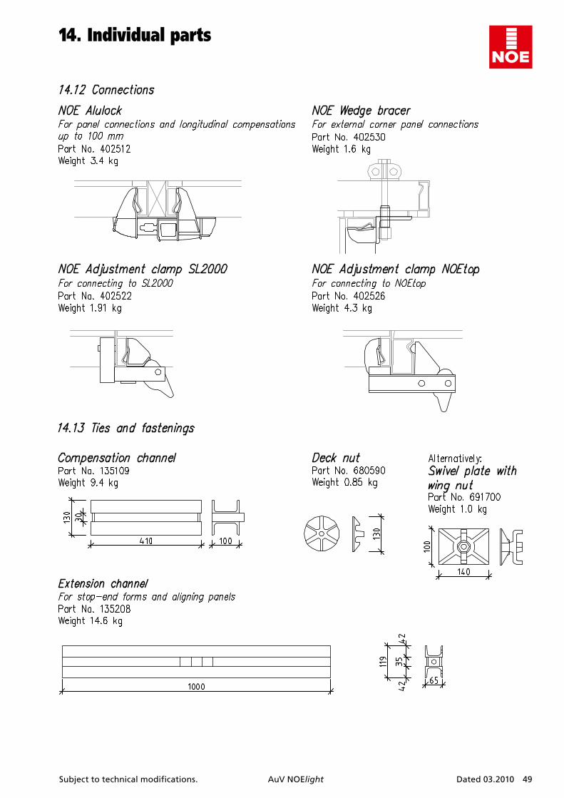
14.Individualparts
50 Dated 03.2010 AuV NOElight Subject to technical modifications.
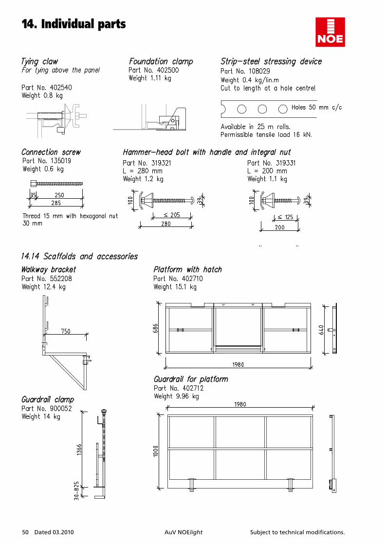
14.Individualparts
Subject to technical modifications. AuV NOElight Dated 03.2010 51
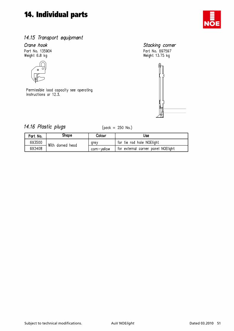
14.Individualparts
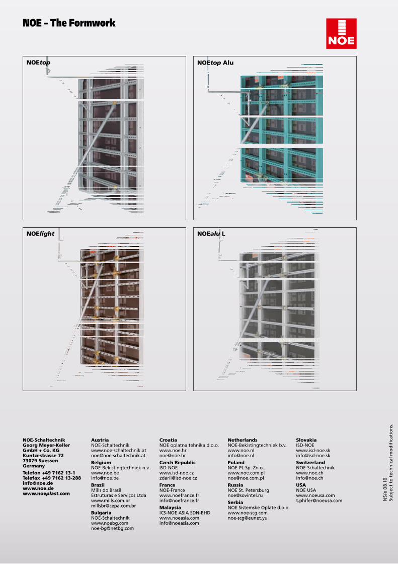
NOE Alutop
NOElight NOE Lalu
NOEtop
NOE-SchaltechnikGeorg Meyer-KellerGmbH + Co. KGKuntzestrasse 7273079 SuessenGermany
Telefon +49 7162 13-1Telefax +49 7162 [email protected] .com
Belgium
Brazil
Bulgaria
France
Malaysia
Netherlands
Poland
Russia
Serbia
Slovakia
USA
plast
Austria Croatia
Czech Republic Switzerland
NOE oplatna tehnika [email protected]
NOE-Bekistingtechniek [email protected]
Mills do BrasilEstruturas e Serviços [email protected]
ICS-NOE ASIA [email protected]
NOE-Bekistingtechniek [email protected]
NOE-PL Sp. [email protected]
NOE St. [email protected]
NOE Sistemske Oplate [email protected]
NOE – The Formwork
NS/
e 0
8.10
Su
bje
ct t
o t
ech
nic
al m
od
ific
atio
ns.
Recommended


![GSV Publications requiring copyright permission Publications requiring copyright permission: 4 GSV Library 929.2 CANE CAN 67. Canty, Wendy. All the shades of Gray. [Photocopy] GSV](https://img.pdfslide.net/doc/110x75/5aa7f75b7f8b9a54748cb5e9/gsv-publications-requiring-copyright-permission-publications-requiring-copyright.jpg)