Slurry Reactors for Gas-to-Liquid Processes: A Review
Tiefeng Wang,* Jinfu Wang, and Yong Jin
Beijing Key Laboratory of Green Reaction Engineering and Technology, Department of Chemical Engineering,Tsinghua UniVersity, Beijing 100084, China
With the dramatic increase in the international oil price, gas-to-liquid processes of Fischer-Tropsch (FT)synthesis, methanol synthesis, and dimethyl ether (DME) synthesis have become increasingly important andreceived much attention from both academic and industrial interests. The slurry reactor has the advantages ofsimple construction, excellent heat transfer performance, online catalyst addition and withdrawal, and areasonable interphase mass transfer rate with low energy input, which make it very suitable for gas-to-liquidprocesses. However, its multiphase flow behaviors are very complex and the multiphase reactor has someremarkable scale-up effects; therefore, extensive studies are still needed for the development and design ofa high-performance slurry reactor. This article gives a state-of-the-art review of the recent studies on theslurry reactor for gas-to-liquid processes. The influences of the superficial gas velocity, operating pressureand temperature, solid concentration, column dimensions, and gas distributor are discussed. Some recentdevelopments in the liquid-solid separation in a slurry reactor are also summarized. The concept of usinginternals to intensify the mass transfer and improve the hydrodynamics is discussed based on both experimentalresults and theoretical analysis. Modeling and simulations of the gas-liquid and gas-liquid-solid flows arebriefly reviewed, with focus on the new trend of coupling the population balance model (PBM) into thecomputational fluid dynamics (CFD) framework to describe the complex bubble behaviors and gas-liquidinterphase interactions. The results of a 3000 ton/year pilot plant for DME synthesis are given, showing thatthe slurry reactor has promising applications in gas-to-liquid processes.
1. Introduction
Fast development of the world economy and increase of theinternational oil price have made the global energy andenvironmental problems increasingly serious. The supply of coalis much more abundant than that of oil; therefore, the develop-ment of coal-based technologies for producing clean fuel is veryimportant for the sustainable development of the economy andof the energy supply for the world. Gas-to-liquid processes ofFischer-Tropsch (FT) synthesis, methanol synthesis, and dim-ethyl ether (DME) synthesis have become increasingly importantand received much attention from both academic and industrialinterests.1-9 Besides providing clean fuel, the products of gas-to-liquid processes can be further produced to many otherchemical products.10
Gas-to-liquid processes have the following common charac-teristics that must be considered in reactor design: (1) Thereactions are strongly exothermic, with-∆Hr ) 165-204 kJ/mol CO for FT synthesis,-∆Hr ) 90.3 kJ/mol CO for methanolsynthesis, and-∆Hr ) 102.2 kJ/mol CO for DME synthesis.(2) The uniform profile of the temperature should be maintainedbecause a nonuniform temperature profile and hot spots maycause a decrease in product selectivity and, more severely, causecatalyst deactivation. (3) Developing a large scale is criticallyimportant from the point view of the economy to produce low-priced fuel. (4) The processes are operated at high temperatureand pressure. Corresponding to the above characteristics, thereactor must realize efficient and rapid removal of the ac-companying large heat of reaction, maintain a uniform temper-ature profile, and be easy to scale up to large dimensions.
Great efforts have been devoted to reactor development tosatisfy the requirements of different gas-to-liquid processes.Several reactor types are currently used for FT synthesis,
methanol synthesis, and DME synthesis. For example, reactorsfor FT synthesis include the multitubular fixed bed, gas-solidfluidized bed, and slurry bubble column reactors.1,3,11 Formethanol synthesis and DME synthesis, the fixed bed, fluidizedbed, slurry bubble column, and slurry airlift reactors were usedor studied.4,7-9,12,13The differences between these several reactortypes are largely related to different approaches to temperaturecontrol and the choice of catalyst.14
Although different reactor types were used for gas-to-liquidprocesses, the majority of attention during the past 10 years,from both academic and industrial interests, was paid to theslurry reactor. The slurry reactor presents the advanced reactortechnology for gas-to-liquid processes. Its advantages includesimple construction, excellent heat transfer performance, onlinecatalyst addition and withdrawal, and reasonable interphase masstransfer rates with low energy input, which make it very suitablefor gas-to-liquid processes. However, its multiphase flowbehaviors are very complex and the multiphase reactor has someremarkable scale-up effects. Under industrial conditions, the highpressure, temperature, and solid concentration have notable andcomplex influences on the bubble behaviors, gas holdup, liquidvelocity, and mass and heat transfer behaviors. Due to thepresence of an additional liquid phase, gas-liquid mass transferlimitations in a gas-liquid-solid slurry system may cause adecrease in the reaction conversion, especially at high solidconcentrations and superficial gas velocities. Further, theseparation of fine catalyst particles from the viscous wax in FTsynthesis is a challenging engineering problem. Therefore,extensive studies are still needed on the hydrodynamics, masstransfer, and liquid-solid separation for the development anddesign of high-performance slurry reactors for gas-to-liquidprocesses.
This article gives a state-of-the-art review of the studies onthe slurry reactor for gas-to-liquid processes. It is organized asfollows. In section 2, the historical and current development of
* To whom correspondence should be addressed. Tel.:+86-10-62797490. Fax:+86-10-62772051. E-mail: [email protected].
5824 Ind. Eng. Chem. Res.2007,46, 5824-5847
10.1021/ie070330t CCC: $37.00 © 2007 American Chemical SocietyPublished on Web 08/02/2007
slurry reactors for FT synthesis, DME synthesis, and methanolsynthesis are overviewed. In section 3, studies on the slurryreactor are discussed in detail, including (1)reactor type, (2)kinetics of gas-to-liquid processes, (3) flow regimes, (4) bubblebehaViors, gas holdup, and liquidVelocity, (5) mass transfer,(6) liquid-solid separation, and (7)hydrodynamics and masstransfer in slurry airlift reactors. In section 4, process inten-sification by using internals is discussed. In section 5, modelingand simulations of gas-liquid and gas-liquid-solid multiphaseflows are selectively reviewed, with focus on the new trend ofcoupling the population balance model (PBM) into the com-putational fluid dynamics (CFD) framework to describe thecomplex bubble behaviors and gas-liquid interphase interac-tions. In section 6, the results of a 3000 ton/year pilot plant fordirect synthesis of DME in a slurry airlift reactor are given.The remarks and conclusions are given in the last section.
2. Slurry Reactor for Gas-to-Liquid Processes
Slurry reactors are extensively used in a variety of chemical,petrochemical, biochemical, and environmental processes forsuch as hydrogenation, oxidation, chlorination, hydroformyla-tion, cell growth, and bioremediation.15,16 Recently, slurryreactors have been considered as the advanced technology for
gas-to-liquid processes. Their advantages include the follow-ing:17,18 (1) simple construction and lower capital required fora large-scale slurry reactor; (2) good performance in temperaturecontrol; (3) feasibility for large capacity; (4) lower pressure lossthat considerably saves the compression cost; (5) online removaland addition of catalyst; (6) lower catalyst amount than the fixedbed reactor due to high catalyst efficiency in a slurry reactor.As a result, there is a trend of shift from the fixed bed reactorto the slurry reactor in gas-to-liquid processes.4,19
2.1. Slurry Reactor for FT Synthesis. At present, themultitubular fixed bed reactor, gas-solid fluidized bed reactor,and gas-liquid-solid slurry reactor, as shown in Figure 1, areused for FT synthesis.11,17,20,21The reactor type and the operatingconditions are the governing factors in the control of productdistribution during FT synthesis. The multitubular fixed bedreactor and slurry reactor were used for the low-temperatureprocess, while the circulating fluidized bed reactor and fixedfluidized bed rector were used for the high-temperature pro-cess.21 The high-temperature process yields large amounts ofolefins, a lower boiling range, and very good gasoline.Substantial amounts of oxygenates are also produced. The low-temperature process yields much more paraffin and linearproducts and can be adjusted to very high wax selectivity. The
Figure 1. Reactor types used for FT synthesis. (a) Fixed bed reactor. (b) Circulating fluidized bed reactor. (c) Slurry buble column reactor.
Ind. Eng. Chem. Res., Vol. 46, No. 18, 20075825
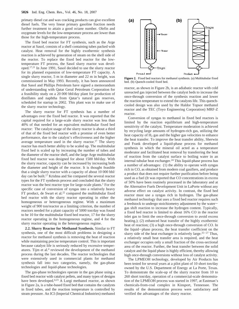
primary diesel cut and wax cracking products can give excellentdiesel fuels. The very linear primary gasoline fraction needsfurther treatment to attain a good octane number. Olefin andoxygenate levels for the low-temperature process are lower thanthose for the high-temperature process.
The fixed bed reactor for FT synthesis, such as the Argereactor at Sasol, consists of a shell containing tubes packed withcatalyst. Heat removal for the highly exothermic synthesisreaction is achieved by generation of steam on the shell side ofthe reactor. To replace the fixed bed reactor for the low-temperature FT process, the Sasol slurry reactor was devel-oped.17,21 In June 1991, Sasol decided to use the slurry reactorfor its planned expansion of low-temperature FT capacity. Asingle slurry reactor, 5 m in diameter and 22 m in height, wascommissioned in May 1993. Recently, it has been announcedthat Sasol and Phillips Petroleum have signed a memorandumof understanding with Qatar Geral Petroleum Corporation fora feasibility study on a 20 000 bbl/day plant for production ofdistillates and naphtha from Qatar’s natural gas reserves,scheduled for startup in 2002. This plant was to make use ofthe slurry reactor technology.
The slurry reactor for FT synthesis has a number ofadvantages over the fixed bed reactor. It was reported that thecapital required for a large-scale slurry reactor was less than40% of that needed for an equivalent multitubular fixed bedreactor: The catalyst usage of the slurry reactor is about a thirdof that of the fixed bed reactor with a promise of even betterperformance, due to the catalyst’s effectiveness and the higheraverage temperature used in the slurry reactor.17 The slurryreactor has much better ability to be scaled up. The multitubularfixed bed is scaled up by increasing the number of tubes andthe diameter of the reactor shell, and the large Arge multitubularfixed bed reactor was designed for about 1500 bbl/day. Withthe slurry reactor, capacity can be increased by increasing boththe diameter and height of the reactor. It is thought feasiblethat a single slurry reactor with a capacity of about 10 000 bbl/day can be built.17 Krishna and Sie compared the several reactortypes for the FT synthesis process and concluded that the slurryreactor was the best reactor type for large-scale plants.1 For thespecific case of conversion of syngas into a relatively heavyFT product, de Swart et al.22 compared the multitubular fixedbed reactor with the slurry reactor operating in either thehomogeneous or heterogeneous regime. With a maximumweight of 900 ton/reactor as a limiting criterion, the number ofreactors needed for a plant capacity of 5000 ton/day was foundto be 10 for the multitubular fixed bed reactor, 17 for the slurryreactor operating in the homogeneous regime, and 4 for theslurry reactor operating in the heterogeneous regime.
2.2. Slurry Reactor for Methanol Synthesis.Similar to FTsynthesis, one of the most difficult problems in designing areactor for methanol synthesis is removing the heat of reactionwhile maintaining precise temperature control. This is importantbecause catalyst life is seriously reduced by excessive temper-atures. Tijm et al.4 reviewed the development of the methanolprocess during the last decades. The reactor technologies thatwere extensively used in commercial plants for methanolsynthesis fall into two categories, namely, the gas-phasetechnologies and liquid-phase technologies.
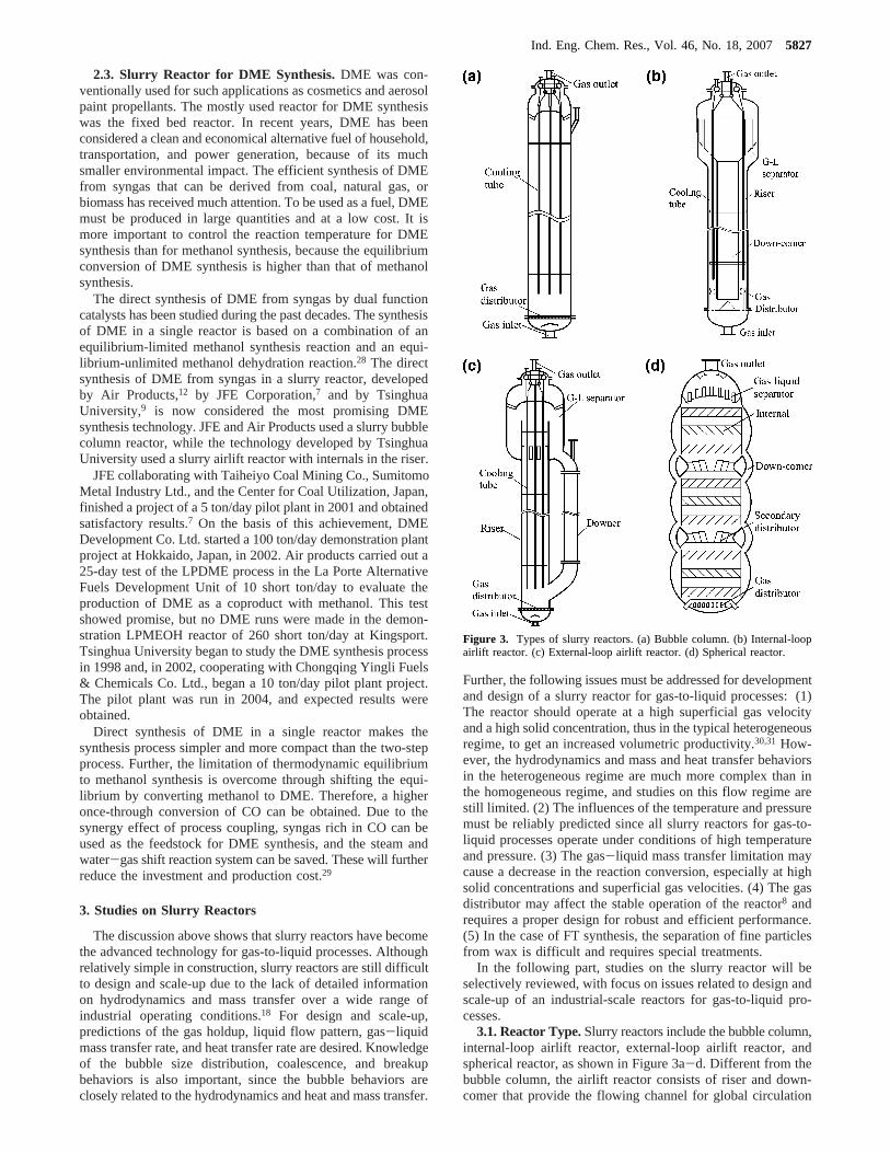
The gas-phase technologies operate in the gas phase using afixed bed reactor with catalyst pellets, and many types of designshave been developed.4,23 A Lurgi methanol reactor, as shownin Figure 2a, is a tube-based fixed bed that contains the catalystsin fixed tubes, and the reaction temperature is controlled bysteam pressure. An ICI (Imperial Chemical Industries) methanol
reactor, as shown in Figure 2b, is an adiabatic reactor with coldunreacted gas injected between the catalyst beds to increase theonce-through conversion of the synthesis reaction and lowerthe reaction temperature to extend the catalysts life. This quench-cooled design was also used by the Haldor Topsor methanolreactor and the TEC (Toyo Engineering Corporation) MRF-Zreactor.
Conversion of syngas to methanol in fixed bed reactors islimited by the reaction equilibrium and high-temperaturesensitivity of the catalyst. Temperature moderation is achievedby recycling large amounts of hydrogen-rich gas, utilizing theheat capacity of H2 gas and the higher gas velocities to enhancethe heat transfer. To improve the heat transfer ability, Sherwinand Frank developed a liquid-phase process for methanolsynthesis in which the mineral oil acted as a temperaturemoderator and facilitated heat removal by transferring the heatof reaction from the catalyst surface to boiling water in aninternal tubular heat exchanger.24 This liquid-phase process hasa number of advantages: (1) the ability to operate with syngasrich in CO, as obtained from modern coal gasifiers, and producea product that does not require further purification before beingused as a fuel (It was reported that CO concentrations in excessof 50% have been routinely processed in the laboratory and atthe Alternative Fuels Development Unit in LaPorte without anyadverse effect on catalyst activity. In contrast, the fixed bedreactor must use a syngas rich in hydrogen. The gas-phasemethanol technology that uses a fixed bed reactor requires sucha feedstock to undergo stoichiometry adjustment by the water-gas shift reaction to increase the hydrogen content. Typically,a fixed bed reactor is limited to about 16% CO in the reactorinlet gas to limit the once-through conversion to avoid excessheating.); (2) enhanced heat transfer of the highly exothermicheat of reaction; (3) a high once-through conversion of CO. Inthe liquid-phase process, the heat transfer coefficient on theslurry side of the heat exchanger is relatively large.25-27 Thus,a relatively small heat transfer area is required, and the heatexchanger occupies only a small fraction of the cross-sectionalarea of the reactor. Further, the heat transfer between the solidcatalyst and the liquid phase is highly efficient, thereby allowinghigh once-through conversions without loss of catalyst activity.
The LPMEOH technology, developed by Air Products hasbeen tested for several years at a pilot plant of 10 short ton/dayowned by the U.S. Department of Energy at La Porte, Texas.To demonstrate the scale-up of the slurry reactor from 10 to260 short ton/day, operation of a commercial-scale demonstra-tion of the LPMEOH process was started in 1997, at Eastman’schemicals-from-coal complex in Kinsport, Tennessee. Theresults of the demonstration process were satisfactory andverified the advantages of the slurry reactor.
Figure 2. Fixed bed reactors for methanol synthesis. (a) Multitubular fixedbed. (b) Quench-cooled fixed bed.
5826 Ind. Eng. Chem. Res., Vol. 46, No. 18, 2007
2.3. Slurry Reactor for DME Synthesis. DME was con-ventionally used for such applications as cosmetics and aerosolpaint propellants. The mostly used reactor for DME synthesiswas the fixed bed reactor. In recent years, DME has beenconsidered a clean and economical alternative fuel of household,transportation, and power generation, because of its muchsmaller environmental impact. The efficient synthesis of DMEfrom syngas that can be derived from coal, natural gas, orbiomass has received much attention. To be used as a fuel, DMEmust be produced in large quantities and at a low cost. It ismore important to control the reaction temperature for DMEsynthesis than for methanol synthesis, because the equilibriumconversion of DME synthesis is higher than that of methanolsynthesis.
The direct synthesis of DME from syngas by dual functioncatalysts has been studied during the past decades. The synthesisof DME in a single reactor is based on a combination of anequilibrium-limited methanol synthesis reaction and an equi-librium-unlimited methanol dehydration reaction.28 The directsynthesis of DME from syngas in a slurry reactor, developedby Air Products,12 by JFE Corporation,7 and by TsinghuaUniversity,9 is now considered the most promising DMEsynthesis technology. JFE and Air Products used a slurry bubblecolumn reactor, while the technology developed by TsinghuaUniversity used a slurry airlift reactor with internals in the riser.
JFE collaborating with Taiheiyo Coal Mining Co., SumitomoMetal Industry Ltd., and the Center for Coal Utilization, Japan,finished a project of a 5 ton/day pilot plant in 2001 and obtainedsatisfactory results.7 On the basis of this achievement, DMEDevelopment Co. Ltd. started a 100 ton/day demonstration plantproject at Hokkaido, Japan, in 2002. Air products carried out a25-day test of the LPDME process in the La Porte AlternativeFuels Development Unit of 10 short ton/day to evaluate theproduction of DME as a coproduct with methanol. This testshowed promise, but no DME runs were made in the demon-stration LPMEOH reactor of 260 short ton/day at Kingsport.Tsinghua University began to study the DME synthesis processin 1998 and, in 2002, cooperating with Chongqing Yingli Fuels& Chemicals Co. Ltd., began a 10 ton/day pilot plant project.The pilot plant was run in 2004, and expected results wereobtained.
Direct synthesis of DME in a single reactor makes thesynthesis process simpler and more compact than the two-stepprocess. Further, the limitation of thermodynamic equilibriumto methanol synthesis is overcome through shifting the equi-librium by converting methanol to DME. Therefore, a higheronce-through conversion of CO can be obtained. Due to thesynergy effect of process coupling, syngas rich in CO can beused as the feedstock for DME synthesis, and the steam andwater-gas shift reaction system can be saved. These will furtherreduce the investment and production cost.29
3. Studies on Slurry Reactors
The discussion above shows that slurry reactors have becomethe advanced technology for gas-to-liquid processes. Althoughrelatively simple in construction, slurry reactors are still difficultto design and scale-up due to the lack of detailed informationon hydrodynamics and mass transfer over a wide range ofindustrial operating conditions.18 For design and scale-up,predictions of the gas holdup, liquid flow pattern, gas-liquidmass transfer rate, and heat transfer rate are desired. Knowledgeof the bubble size distribution, coalescence, and breakupbehaviors is also important, since the bubble behaviors areclosely related to the hydrodynamics and heat and mass transfer.
Further, the following issues must be addressed for developmentand design of a slurry reactor for gas-to-liquid processes: (1)The reactor should operate at a high superficial gas velocityand a high solid concentration, thus in the typical heterogeneousregime, to get an increased volumetric productivity.30,31 How-ever, the hydrodynamics and mass and heat transfer behaviorsin the heterogeneous regime are much more complex than inthe homogeneous regime, and studies on this flow regime arestill limited. (2) The influences of the temperature and pressuremust be reliably predicted since all slurry reactors for gas-to-liquid processes operate under conditions of high temperatureand pressure. (3) The gas-liquid mass transfer limitation maycause a decrease in the reaction conversion, especially at highsolid concentrations and superficial gas velocities. (4) The gasdistributor may affect the stable operation of the reactor8 andrequires a proper design for robust and efficient performance.(5) In the case of FT synthesis, the separation of fine particlesfrom wax is difficult and requires special treatments.
In the following part, studies on the slurry reactor will beselectively reviewed, with focus on issues related to design andscale-up of an industrial-scale reactors for gas-to-liquid pro-cesses.
3.1. Reactor Type.Slurry reactors include the bubble column,internal-loop airlift reactor, external-loop airlift reactor, andspherical reactor, as shown in Figure 3a-d. Different from thebubble column, the airlift reactor consists of riser and down-comer that provide the flowing channel for global circulation
Figure 3. Types of slurry reactors. (a) Bubble column. (b) Internal-loopairlift reactor. (c) External-loop airlift reactor. (d) Spherical reactor.
Ind. Eng. Chem. Res., Vol. 46, No. 18, 20075827
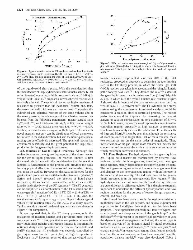
of the liquid-solid slurry phase. With the consideration thatthe manufacture of large cylindrical reactors (such as those 6-10m in diameter) operating at high pressure (such as 10 MPa) isvery difficult, Jin et al.32 proposed a novel spherical reactor withrelatively thin wall. The spherical reactor has higher mechanicalresistance to pressure than the cylindrical column and, thus,decreases the wall thickness and reactor cost. Comparing thecylindrical and spherical reactors of the same volume and atthe same pressure, the advantages of the spherical reactor canbe seen from the following parameters: reactor surface ratioFs/Fc ) 0.875; wall thickness ratioδs/δc ) 0.5; reactor weightratioWs/Wc ) 0.437; reactor price ratio$s/$c ≈ Ws/Wc ) 0.437.Further, in a reactor consisting of multiple spherical units withnovel internals, not only can the distribution of local parametersbe uniform in the radial direction, but also the liquid-phase back-mixing can be effectively decreased. The spherical reactor haseconomical feasibility and the great potential for large-scaleproduction in the gas-to-liquid processes.
3.2. Kinetics of Gas-to-Liquid Processes.Although thisreview focuses on the engineering aspects of the slurry reactorfor the gas-to-liquid processes, the reaction kinetics is firstdiscussed briefly here with the consideration that the reactionkinetics is fundamental to the process and provides the basisfor why physical effects, such as mass and heat transfer, mixing,etc., must be studied. Reviews on the reaction kinetics for thegas-to-liquid processes are available in the literature. Cybulski,25
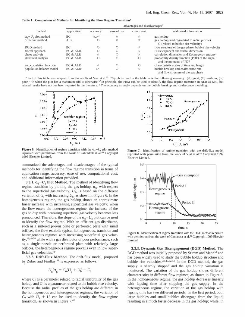
Setinc and Levec33 reviewed the kinetics of liquid-phasemethanol synthesis. Van der Laan and Beenackers reviewed thekinetics and selectivity of the FT synthesis.34 The FT synthesiscan be simplified as a combination of the FT reaction and thewater-gas shift reaction (WGS): (1 FT) CO+ (1 + n/2)H2 fCHn + H2O; (2 WGS) CO+ H2O f CO2 + H2. And, thereaction rates satisfyrFT ) - rCO - rWGS. Figure 4 shows typicalvalues of the reaction rates,rFT and rWGS, in a slurry system.Typical reaction rates of methanol synthesis are also shown inFigure 4 for comparison.
It was reported that, in the FT slurry process, only theresistances of reaction kinetics and gas-liquid mass transferwere significant.36,37Thus, quantitative comparison between thegas-liquid mass transfer and reaction kinetics is important foroptimum design and operation of the reactor. Satterfield andHuff36 claimed that FT synthesis was severely controlled bygas-liquid mass transfer, particularly at high temperatures.Deckwer et al.,37 however, reported that the gas-liquid mass
transfer resistance represented less than 20% of the totalresistance. proposed an approach to determine the rate-limitingstep in the FT slurry process, in which the water-gas shift(WGS) reaction was taken into account and the “singular kineticpath” concept was used.38 They defined the relative extent ofthe gas-liquid mass transfer resistanceâ as (1/kla)/[1/kla+1/ko(φi)], in which ko is the overall kinetics rate constant. Figure5 showed the influence of the catalyst concentration onâ aswell as (CO+ H2) conversion.38 The FT synthesis in a slurrysystem using the commercial iron-based catalysts could beconsidered a reaction kinetics-controlled process. The reactorperformance could be improved by increasing the catalystactivity or catalyst concentration up to a maximum of 37-40wt %. In both cases, the reactor would approach a mass transfer-controlled regime, especially at high catalyst concentrationwhich would markedly increase the bubble size. From the resultsof Inga and Morsi,38 it can be seen that although the resistanceof reaction kinetics is larger than that of mass transfer, thesetwo resistances are on the same order of magnitude. Thus,intensification of the gas-liquid mass transfer can increase theconversion and increase the critical catalyst concentration atwhich maximum conversion is obtained.
3.3. Flow Regimes.The hydrodynamics in a gas-liquid orgas-liquid-solid reactor are characterized by different flowregimes, namely, the homogeneous, transition, and heteroge-neous regimes, mainly depending on the superficial gas velocity.The homogeneous regime exists at low superficial gas velocitiesand changes to the heterogeneous regime with an increase inthe superficial gas velocity. The industrial interest for gas-to-liquid processes is in the heterogeneous flow regime.1,39 Thehydrodynamics, heat and mass transfer, and mixing behaviorare quite different in different regimes.40 It is therefore extremelyimportant to understand the different hydrodynamics and flowregime transitions for the purpose of reactor design, operation,control, and scale-up.
Much work has been done to study the regime transition inmultiphase flows in the last decades, and several experimentalapproaches for identifying flow regime transition have beenproposed. These approaches generally fall into two types: onetype is based on a sharp variation of the gas holdup40 or thedrift flux41,42with respect to the superficial gas velocity or usesthe dynamic gas disengagement technique; the other type isbased on analysis of the dynamic signal-by-signal processingmethods such as statistical analysis,43,44 fractal analysis,45 andchaotic analysis.46 In recent years, regime identification methodsbased on theoretical analysis, such as linear analysis47 and thepopulation balance model,48 were also developed. Table 1
Figure 4. Typical reaction rates for FT synthesis and methanol synthesisin a slurry system. For FT synthesis, H2/CO feed ratio) 1.7,T ) 270°C,P ) 1.308 MPa, and data is from the work of Raje and Davis.35 For CH3-OH synthesis, H2:CO:CO2 ) 50.9:39.5:4.7,T ) 230 °C, P ) 3.45 MPa,and data is from the work of Sˇetinc and Levec.33
Figure 5. Effect of catalyst concentration onâ and (H2 + CO) conversion.â is defined as (1/kla)/[1/kla + 1/ko(φi)], in which ko is the overall kineticsrate constant. This figure has been adapted from the work of Inga andMorsi.38
5828 Ind. Eng. Chem. Res., Vol. 46, No. 18, 2007
summarized the advantages and disadvantages of the typicalmethods for identifying the flow regime transition in terms ofapplication range, accuracy, ease of use, computational cost,and additional information provided.
3.3.1.rg-Ug Plot Method. The method of identifying flowregime transition by plotting the gas holdup,Rg, with respectto the superficial gas velocity,Ug, is based on the differentvariation ofRg with increasingUg, as shown in Figure 6. In thehomogeneous regime, the gas holdup shows an approximatelinear increase with increasing superficial gas velocity; whenthe flow enters the heterogeneous regime, the increase of thegas holdup with increasing superficial gas velocity becomes lesspronounced. Therefore, the slope of theRg-Ug plot can be usedto identify the flow regime. With an efficient gas distributor,such as a sintered porous plate or perforated plate with smallorifices, the flow exhibits typical homogeneous, transition andheterogeneous regimes with increasing superficial gas veloc-ity;40,49,50while with a gas distributor of poor performance, suchas a single nozzle or perforated plate with relatively largeorifices, the heterogeneous regime prevails even in low super-ficial gas velocities.49
3.3.2. Drift-Flux Method. The drift-flux model, proposedby Zuber and Findlay,41 is expressed as follows:
whereC0 is a parameter related to radial uniformity of the gasholdup andC1 is a parameter related to the bubble rise velocity.Because the radial profiles of the gas holdup are different inthe homogeneous and heterogeneous regimes, the variation ofC0 with Ug + Ul can be used to identify the flow regimetransition, as shown in Figure 7.42
3.3.3. Dynamic Gas Disengagement (DGD) Method.TheDGD method was initially proposed by Sriram and Mann51 andhas been widely used to study the bubble holdup structure andbubble rise velocities.39,49,52,53 In the DGD method, the gassupply is sharply stopped and the gas holdup variation ismonitored. The variation of the gas holdup shows differentcharacteristics in different flow regimes, as shown in Figure 8.In the homogeneous regime, the gas holdup decreases linearlywith lapsing time after stopping the gas supply. In theheterogeneous regime, the variation of the gas holdup withlapsing time has two different periods: in the first period, bothlarge bubbles and small bubbles disengage from the liquid,resulting in a much faster decrease in the gas holdup; while, in
Table 1. Comparison of Methods for Identifying the Flow Regime Transitiona
advantages and disadvantagesb
method application accuracy ease of use comp. cost additional information
Rg-Ug plot method BC g,×c g g gas holdupdrift-flux method ALR O g g gas holdup, andC0 (related to radial profile),
C1(related to bubble rise velocity)DGD method BC O O g flow structure of the gas phase, bubble rise velocityfractal approach BC & ALR O O × Hurst exponent and fractal dimensionchaos analysis BC & ALR g O × correlation dimension and Kolmogorov entropystatistical analysis BC & ALR O O O probability density function (PDF) of the signal
and the moments of PDFautocorrelation function BC & ALR g O O characteristic scales of time and lengthpopulation balance model BC & ALRd Oe O × bubble breakup and coalescence rate
and flow structure of the gas phase
a Part of this table was adapted from the results of Vial et al.55 b Symbols used in the table have the following meaning: (g) good, (O) medium, (×)poor. c g when the plot has a maximum and× otherwise.d In principle, the PBM can be used to identify the flow regime transition in ALR as well, butrelated results have not yet been reported in the literature.e The accuracy strongly depends on the bubble breakup and coalescence modeling.
Figure 6. Identification of regime transition with theRg-Ug plot methodreprinted with permission from the work of Zahradnı´k et al.40 Copyright1996 Elsevier Limited.
Ug/Rg ) C0(Ug + Ul) + C1
Figure 7. Identification of regime transition with the drift-flux modelreprinted with permission from the work of Vial et al.42 Copyright 1992Elsevier Limited.
Figure 8. Identification of regime transition with the DGD method reprintedwith permission from the work of Camarasa et al.49 Copyright 1999 ElsevierLimited.
Ind. Eng. Chem. Res., Vol. 46, No. 18, 20075829
the second period, all large bubbles have disengaged from thesystem and only small bubbles disengage from the liquid,resulting in a slower decrease in the gas holdup.
3.3.4. Dynamic Signal Analysis Method.Drahoset al.43
analyzed the pressure fluctuations by a fractal approach andfound that the value of the Hurst exponent computed from therescaled range analysis could be used to distinguish the flowregime transition. Bakshi et al.54 studied the regime transitionin a gas-liquid bubble column using multiresolution analysisof the gas holdup signal and found that the intermittence of themeasured signal characterized the transition from the homoge-neous to heterogeneous regime. Letzel et al.46 used the chaoticinvariant Kolmogorov entropy to quantify the chaos dynamicsin bubble columns, and showed that Kolmogorov entropyindicates a sharp transition from the homogeneous to hetero-geneous regime. Vial et al.55 compared several methods ofregime identification based on analysis of pressure fluctuations,including statistical analysis, spectral analysis, fractal analysis,chaotic analysis, and time-frequency analysis, both in a bubblecolumn and an external-loop airlift reactor. Their ability todetermine regime transition and to extract regime features iscompared. A new simple and efficient method was proposedfor regime identification based on the autocorrelation function.This method also provided quantitative information about thecharacteristic time and the axial dimension of the flow structure.Lin et al.56 estimated four chaotic invariants, namely, correlationdimension, largest Lyapunov exponent, metric entropy, andmutual information in different flow regimes. The transitionsuperficial gas velocity was determined by the sharp increaseor decrease of these obtained chaotic invariants.
3.3.5. Population Balance Model Method.The aboveapproaches need experimental data and do not give a directexplanation on the mechanism of regime transition. Due to thecomplexity of gas-liquid flows, it is very difficult to predictthe regime transition by theoretical modeling. Olmos et al.57
modeled the gas-liquid flow with the population balance model(PBM), and the results showed that it was possible to predictnumerically the regime transition as long as several gas phaseswere considered. In their work, 10 bubble classes of diametersranging from 1 to 10 mm were used. This bubble division maycause remarkable errors because bubbles much larger than 10mm exist in the heterogeneous regime. The authors pointed outthat their study did not pretend to describe exactly the complexcoalescence and breakup phenomena occurring in bubblecolumns but rather showed the possibilities of the applicationof population balance equations. They used the bubble breakupand coalescence kernels proposed by Luo and Svendsen58,59andPrince and Blanch,60 respectively. However, these bubblebreakup and coalescence models have some limitations.61-63
Furthermore, it is necessary to consider the multiple bubblebreakup and coalescence mechanisms to reasonably predict thebubble size distribution both in the homogeneous and hetero-geneous regimes.48,63
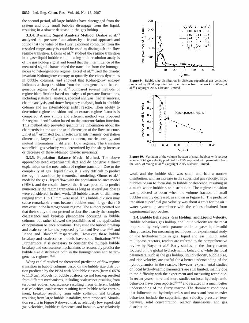
Wang et al.48 studied the theoretical prediction of flow regimetransition in bubble columns based on the bubble size distribu-tion predicted by the PBM with 30 bubble classes (from 0.0576to 11.6 cm). Models for bubble coalescence and breakup resultedfrom different mechanisms, including coalescence resulting fromturbulent eddies, coalescence resulting from different bubblerise velocities, coalescence resulting from bubble wake entrain-ment, breakup resulting from eddy collision, and breakupresulting from large bubble instability, were proposed. Simula-tion results in Figure 9 showed that, at relatively low superficialgas velocities, bubble coalescence and breakup were relatively
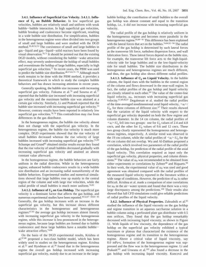
weak and the bubble size was small and had a narrowdistribution; with an increase in the superficial gas velocity, largebubbles began to form due to bubble coalescence, resulting ina much wider bubble size distribution. The regime transitionwas predicted to occur when the volume fraction of smallbubbles sharply decreased, as shown in Figure 10. The predictedtransition superficial gas velocity was about 4 cm/s for the air-water system, in accordance with the values obtained fromexperimental approaches.
3.4. Bubble Behaviors, Gas Holdup, and Liquid Velocity.Bubble behaviors, gas holdup, and liquid velocity are the mostimportant hydrodynamic parameters in a gas-liquid-solidslurry reactor. For measuring techniques for experimental studyon the hydrodynamics in gas-liquid and gas-liquid-solidmultiphase reactors, readers are referred to the comprehensivereview by Boyer et al.64 Early studies on the slurry reactorfocused on the global hydrodynamic behaviors, while the localparameters, such as the gas holdup, liquid velocity, bubble size,and rise velocity, are useful for a better understanding of thehydrodynamics in the reactor. However, experimental studieson local hydrodynamic parameters are still limited, mainly dueto the difficulty with the experiment and measuring technique.In recent years, more and more studies on local hydrodynamicbehaviors have been reported65-69 and resulted in a much betterunderstanding of the slurry reactor. The dominant conditionsthat influence the hydrodynamics and mass and heat transferbehaviors include the superficial gas velocity, pressure, tem-perature, solid concentration, reactor dimensions, and gasdistribution.
Figure 9. Bubble size distribution in different superficial gas velocitiespredicted by PBM reprinted with permission from the work of Wang etal.48 Copyright 2005 Elsevier Limited.
Figure 10. Variation of the volume fraction of small bubbles with respectto superficial gas velocity predicted by PBM reprinted with permission fromthe work of Wang et al.48 Copyright 2005 Elsevier Limited.
5830 Ind. Eng. Chem. Res., Vol. 46, No. 18, 2007
3.4.1. Influence of Superficial Gas Velocity. 3.4.1.1. Influ-ence of Ug on Bubble Behavior. In low superficial gasvelocities, bubbles are relatively small and uniform with weakbubble-bubble interaction. In high superficial gas velocities,bubble breakup and coalescence become significant, resultingin a wide bubble size distribution. For simplification, bubblesin the heterogeneous regime were often divided into two groupsof small and large bubbles and were studied with the DGDmethod.39,49,52,53The coexistence of small and large bubbles ingas-liquid and gas-liquid-solid reactors have been found byvisual observation.70,71It should be pointed out that the existingDGD models, without considering the bubble-wake attractioneffect, may severely underestimate the holdup of small bubblesand overestimate the holdup of large bubbles, especially in highsuperficial gas velocities.72 In recent years, the PBM was usedto predict the bubble size distribution.48,57,63,73-75 Although muchwork remains to be done with the PBM method, it provides atheoretical framework in which to study the complex bubblebehaviors and has drawn increasing attention in recent years.
Generally speaking, the bubble size increases with increasingsuperficial gas velocity. Fukuma et al.76 and Saxena et al.77
reported that the bubble size increased with increasing superficialgas velocity and the maximum bubble size was attained at acertain gas velocity. Similarly, Li and Prakash reported that thebubble size increased with increasing superficial gas velocity.53
However, contrary results have been reported in relatively lowsuperficial gas velocities.78,79This contradiction may rise fromdifferences in the gas distributor.
In the homogeneous regime, the bubble rise velocity almostdoes not change with the superficial gas velocity. In theheterogeneous regime, the bubble rise velocity is much morecomplex. DGD experiments showed that the rise velocity ofsmall bubbles decreased whereas the rise velocity of largebubbles increased with increasing superficial gas velocity.53,80
Schumpe and Grund81 obtained similar results except they foundthat the rise velocity of small bubbles decreased gradually withincreasing superficial gas velocity and attained an almostconstant value afterward.
In the homogeneous regime, the bubble behaviors are fairlyuniform in the radial direction. While in the heterogeneousregime, enhanced bubble coalescence results in a wide bubblesize distribution and an increasing radial nonuniformity of thebubble behaviors. Experimental studies and numerical simula-tions showed that large bubbles rose up mainly in the centralregion of the column and with large rise velocities, while theradial profile of small bubbles is much more uniform.74,82
3.4.1.2. Influence ofUg on Gas Holdup. The superficial gasvelocity is a dominant factor that affects the gas holdup, andnumerous experimental studies have been reported.39,52,67-69,83-85
Generally, the gas holdup increases with an increase in thesuperficial gas velocity, but this increase shows differentcharacteristics in the homogeneous and heterogeneousregimes:67,85 the average gas holdup increases almost linearlywith increasing superficial gas velocity in the homogeneousregime, while this increase is less pronounced in the heteroge-neous regime, because large bubbles are formed due to bubblecoalescence and these large bubbles have a notable bubble-wake attraction effect.74,86
On the basis of the DGD experimental results, Krishna etal.87,88 proposed a two-class bubble model, which has beenwidely used in studies on the heterogeneous regime. Krishnaet al.52 and Hyndman et al.39 found that in the heterogeneousregime the overall gas holdup increased with increasingsuperficial gas velocity, mainly due to an increase in the large-
bubble holdup; the contribution of small bubbles to the overallgas holdup was almost constant and equal to the transitionholdup, i.e., it did not increase with increasing superficial gasvelocity.
The radial profile of the gas holdup is relatively uniform inthe homogeneous regime and becomes more parabolic in theheterogeneous regime.85,89-91 This difference has been explainedwith the lateral forces that act on the bubbles.74,84,92-94 The radialprofile of the gas holdup is determined by such lateral forcesas the transverse lift force, turbulent dispersion force, and walllubrication force. These lateral forces depend on the bubble size,for example, the transverse lift force acts to the high-liquid-velocity side for large bubbles and to the low-liquid-velocityside for small bubbles. The bubble size distributions in thehomogeneous and heterogeneous regimes are much different,and thus, the gas holdup also shows different radial profiles.
3.4.1.3. Influence ofUg on Liquid Velocity. In the bubblecolumn, the liquid rises with the bubbles in the central regionof the column and flows downward in the near-wall region. Infact, the radial profiles of the gas holdup and liquid velocityare closely related to each other.95 The value of the center-lineliquid velocity, ul0, increases with increasing superficial gasvelocity.67,89,96,97Degaleesan et al. studied the radial profilesof the time-averaged nondimensional axial liquid velocity,<ul>/Ug, for three columns of different size.67 Their results showedthat the variation of the liquid velocity with respect to thesuperficial gas velocity depended on both the flow regime andcolumn diameter. In the 14 cm column, the radial profiles of<ul>/Ug fell into two groups: one forUg values of 2.4 and 4.8cm/s, and the other forUg values of 9.6 and 12 cm/s. Thesetwo group clearly represented the homogeneous and heteroge-neous regimes, respectively. A similar trend was observed inthe 19 cm column, while the radial profiles of<ul>/Ug for the44 cm column did not overlap. Wu and Al-Dahhan proposed acorrelation, which involved two parameters of the radial profileof the gas holdup, for prediction of the radial profile of the axialliquid velocity. This correlation required as input only thesuperficial gas velocity, physical properties, and column dimen-sions.95 The value oful0 was recommended to be obtained fromeither experiments or correlations by Zehner98 and Riquarts.99
In their work, the experimental value oful0 was used and goodagreement was obtained compared with the radial profiles ofthe measured liquid velocity reported in the literature within awide range of conditions. However, the prediction oful0 is ratherdifficult. Krishna et al. made a comparison of nine correlationsfor ul0 in the air-water system and found that there was a verylarge discrepancy among the predictions.100 Their results alsoshowed that full CFD simulations could give reliable predictionsof radial profiles of the liquid velocity.
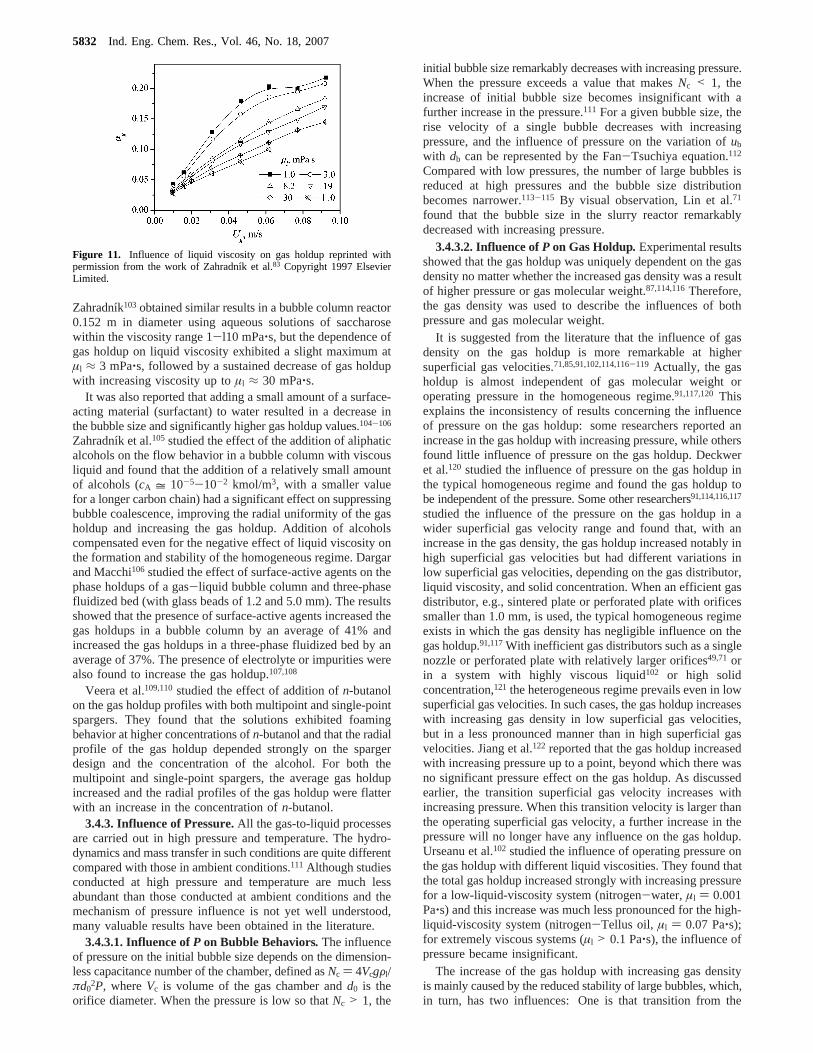
3.4.2. Influence of Physical Properties.Zahradnı´k et al.83
studied the influence of the liquid viscosity on the gas holdupand regime transition in an aqueous saccharose solution in abubble column using a perforated plate gas distributor with 0.5mm orifices. They found that the gas holdup remarkablydecreased with increasing liquid viscosity, as shown in Figure11. With liquids of low viscosity, the dependence of the gasholdup on the superficial gas velocity exhibited a typicalmaximum or plateau that characterized the existence of thehomogeneous regime and its transition to the heterogeneousregime. Above a critical value of liquid viscosity, say8.0 mPa‚s, formation of the homogeneous regime was sup-pressed and the flow was in the heterogeneous regime. Li andPrakash101 and Urseanu et al.102 also found a decrease in thegas holdup with increasing liquid viscosity. Kuncova´ and
Ind. Eng. Chem. Res., Vol. 46, No. 18, 20075831
Zahradnı´k103 obtained similar results in a bubble column reactor0.152 m in diameter using aqueous solutions of saccharosewithin the viscosity range 1-l10 mPa‚s, but the dependence ofgas holdup on liquid viscosity exhibited a slight maximum atµl ≈ 3 mPa‚s, followed by a sustained decrease of gas holdupwith increasing viscosity up toµl ≈ 30 mPa‚s.
It was also reported that adding a small amount of a surface-acting material (surfactant) to water resulted in a decrease inthe bubble size and significantly higher gas holdup values.104-106
Zahradnı´k et al.105 studied the effect of the addition of aliphaticalcohols on the flow behavior in a bubble column with viscousliquid and found that the addition of a relatively small amountof alcohols (cA = 10-5-10-2 kmol/m3, with a smaller valuefor a longer carbon chain) had a significant effect on suppressingbubble coalescence, improving the radial uniformity of the gasholdup and increasing the gas holdup. Addition of alcoholscompensated even for the negative effect of liquid viscosity onthe formation and stability of the homogeneous regime. Dargarand Macchi106 studied the effect of surface-active agents on thephase holdups of a gas-liquid bubble column and three-phasefluidized bed (with glass beads of 1.2 and 5.0 mm). The resultsshowed that the presence of surface-active agents increased thegas holdups in a bubble column by an average of 41% andincreased the gas holdups in a three-phase fluidized bed by anaverage of 37%. The presence of electrolyte or impurities werealso found to increase the gas holdup.107,108
Veera et al.109,110studied the effect of addition ofn-butanolon the gas holdup profiles with both multipoint and single-pointspargers. They found that the solutions exhibited foamingbehavior at higher concentrations ofn-butanol and that the radialprofile of the gas holdup depended strongly on the spargerdesign and the concentration of the alcohol. For both themultipoint and single-point spargers, the average gas holdupincreased and the radial profiles of the gas holdup were flatterwith an increase in the concentration ofn-butanol.
3.4.3. Influence of Pressure.All the gas-to-liquid processesare carried out in high pressure and temperature. The hydro-dynamics and mass transfer in such conditions are quite differentcompared with those in ambient conditions.111 Although studiesconducted at high pressure and temperature are much lessabundant than those conducted at ambient conditions and themechanism of pressure influence is not yet well understood,many valuable results have been obtained in the literature.
3.4.3.1. Influence ofP on Bubble Behaviors. The influenceof pressure on the initial bubble size depends on the dimension-less capacitance number of the chamber, defined asNc ) 4VcgFl/πd0
2P, whereVc is volume of the gas chamber andd0 is theorifice diameter. When the pressure is low so thatNc > 1, the
initial bubble size remarkably decreases with increasing pressure.When the pressure exceeds a value that makesNc < 1, theincrease of initial bubble size becomes insignificant with afurther increase in the pressure.111 For a given bubble size, therise velocity of a single bubble decreases with increasingpressure, and the influence of pressure on the variation ofub
with db can be represented by the Fan-Tsuchiya equation.112
Compared with low pressures, the number of large bubbles isreduced at high pressures and the bubble size distributionbecomes narrower.113-115 By visual observation, Lin et al.71
found that the bubble size in the slurry reactor remarkablydecreased with increasing pressure.
3.4.3.2. Influence ofP on Gas Holdup. Experimental resultsshowed that the gas holdup was uniquely dependent on the gasdensity no matter whether the increased gas density was a resultof higher pressure or gas molecular weight.87,114,116Therefore,the gas density was used to describe the influences of bothpressure and gas molecular weight.
It is suggested from the literature that the influence of gasdensity on the gas holdup is more remarkable at highersuperficial gas velocities.71,85,91,102,114,116-119 Actually, the gasholdup is almost independent of gas molecular weight oroperating pressure in the homogeneous regime.91,117,120Thisexplains the inconsistency of results concerning the influenceof pressure on the gas holdup: some researchers reported anincrease in the gas holdup with increasing pressure, while othersfound little influence of pressure on the gas holdup. Deckweret al.120 studied the influence of pressure on the gas holdup inthe typical homogeneous regime and found the gas holdup tobe independent of the pressure. Some other researchers91,114,116,117
studied the influence of the pressure on the gas holdup in awider superficial gas velocity range and found that, with anincrease in the gas density, the gas holdup increased notably inhigh superficial gas velocities but had different variations inlow superficial gas velocities, depending on the gas distributor,liquid viscosity, and solid concentration. When an efficient gasdistributor, e.g., sintered plate or perforated plate with orificessmaller than 1.0 mm, is used, the typical homogeneous regimeexists in which the gas density has negligible influence on thegas holdup.91,117With inefficient gas distributors such as a singlenozzle or perforated plate with relatively larger orifices49,71 orin a system with highly viscous liquid102 or high solidconcentration,121 the heterogeneous regime prevails even in lowsuperficial gas velocities. In such cases, the gas holdup increaseswith increasing gas density in low superficial gas velocities,but in a less pronounced manner than in high superficial gasvelocities. Jiang et al.122 reported that the gas holdup increasedwith increasing pressure up to a point, beyond which there wasno significant pressure effect on the gas holdup. As discussedearlier, the transition superficial gas velocity increases withincreasing pressure. When this transition velocity is larger thanthe operating superficial gas velocity, a further increase in thepressure will no longer have any influence on the gas holdup.Urseanu et al.102 studied the influence of operating pressure onthe gas holdup with different liquid viscosities. They found thatthe total gas holdup increased strongly with increasing pressurefor a low-liquid-viscosity system (nitrogen-water,µl ) 0.001Pa‚s) and this increase was much less pronounced for the high-liquid-viscosity system (nitrogen-Tellus oil, µl ) 0.07 Pa‚s);for extremely viscous systems (µl > 0.1 Pa‚s), the influence ofpressure became insignificant.
The increase of the gas holdup with increasing gas densityis mainly caused by the reduced stability of large bubbles, which,in turn, has two influences: One is that transition from the
Figure 11. Influence of liquid viscosity on gas holdup reprinted withpermission from the work of Zahradnı´k et al.83 Copyright 1997 ElsevierLimited.
5832 Ind. Eng. Chem. Res., Vol. 46, No. 18, 2007
homogeneous to heterogeneous regime is delayed, and the gasholdup at the transition point is also higher;85,102,116,123The otheris that breakup of large bubbles is enhanced,114 resulting in adecrease in the large-bubble size and an increase in the large-bubble holdup.123 Further, some studies showed that thecoalescence rate decreased with increasing pressure124 and theinitial bubble sizes near the gas distributor decreased at elevatedpressure,125 both of which are favorable to decrease the bubblesize and increase the gas holdup.
3.4.4. Influence of Temperature.With an increase in thetemperature, the liquid viscosity and surface tension decreaseand result in a smaller average bubble size and a narrowerbubble size distribution. Saxena et al.77 investigated the bubblecolumns with gas-liquid and gas-liquid-solid systems withina 297-343 K temperature range and found a temperaturedependence of the gas holdup only in the two-phase system.Soong et al.126 found that the Sauter mean bubble diameterremarkably decreased with increasing temperature at a constantsuperficial gas velocity in a gas-liquid-solid slurry system.Lin et al.71 found that, for a fixed pressure and superficial gasvelocity, the increasing temperature generally increased the gasholdup but this influence was rather complex. Pohorecki et al.127
found a decrease in the bubble swarm velocity and an increasein the gas holdup with increasing temperature. Scha¨fer et al.128
experimentally studied the influences of the gas density, surfacetension, liquid viscosity, gas distributor, and operating conditionson the bubble size. They reported that the stable bubble sizedecreased with a decrease in the liquid viscosity or surfacetension and increasing temperatures resulted in reduced bubblesize. Lau et al.129 found that the influence of the temperature isgenerally not very notable and this temperature influence is moresignificant in high pressures than in low pressures.
3.4.5. Influence of Solid Concentration.To increase thereactor capacity and catalyst loading, the slurry reactor shouldbe operated in high solid concentrations. However, the increaseof solid concentration may have a negative influence on thehydrodynamics and gas-liquid mass transfer. It is thereforeimportant to identify practical operational limits and the designimplications of increasing solid concentrations in the column.For example, the gas distributor design and column startupprocedure could be influenced by high solid concentrations.18
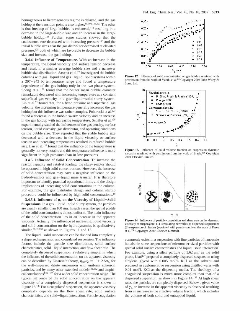
3.4.5.1. Influence ofrs on the Viscosity of Liquid-SolidSuspensions. In a gas-liquid-solid slurry system, the particlesare usually smaller than 100µm. In such cases, the spatial profileof the solid concentration is almost uniform. The main influenceof the solid concentration lies in an increase in the apparentviscosity. Actually, the influence of increasing liquid viscosityand solid concentration on the hydrodynamics is qualitativelysimilar,80,83,130as shown in Figures 11 and 12.
The liquid-solid suspension can be divided into completelya dispersed suspension and coagulated suspension. The influencefactors include the particle size distribution, solid surfacecharacteristics, solid-liquid interaction, and flow shear rate. Thecompletely dispersed suspension is relatively simple, in whichthe influence of the solid concentration on the apparent viscositycan be described by Einstein’s theory,ηsus/ηl ) 1 + 2.5Rs, forthe well-dispersed dilute suspension with uniform sphericalparticles, and by many other extended models131,132and empiri-cal correlations133-135 for a wider solid concentration range. Thetypical influence of the solid concentration on the apparentviscosity of a completely dispersed suspension is shown inFigure 13.136For a coagulated suspension, the apparent viscositycomplexly depends on the flow shear rate, solid surfacecharacteristics, and solid-liquid interaction. Particle coagulation
commonly exists in a suspension with fine particles of nanoscalebut also in some suspensions of micrometer-sized particles withspecial solid surface characteristics and liquid-solid interaction.For example, using a silica particle of 1.62µm as the solidphase, Usui137prepared a completely dispersed suspension usingethylene glycol with 0.005 mol/L KCl as the solvent andprepared an agglomerative suspension using distilled water with0.01 mol/L KCl as the dispersing media. The rheology of acoagulated suspension is much more complex than that of adispersed suspension, as shown in Figure 14.138 At high shearrates, the particles are completely dispersed. Below a given valueof γs, an increase in the apparent viscosity is observed resultingfrom an increase in the effective volume fraction, which includesthe volume of both solid and entrapped liquid.
Figure 12. Influence of solid concentration on gas holdup reprinted withpermission from the work of Vandu et al.80 Copyright 2004 John Wiley &Sons, Ltd.
Figure 13. Influence of solid volume fraction on suspension dynamicviscosity reprinted with permission from the work of Brady.136 Copyright2001 Elsevier Limited.
Figure 14. Influence of particle coagulation and shear rate on the dynamicviscosity of suspension: (1) Percolating network; (2) dispersed suspension;(3) suspension of clusters (reprinted with permission from the work of Perezet al.138 Copyright 2000 Elsevier Limited).
Ind. Eng. Chem. Res., Vol. 46, No. 18, 20075833
Although the particles in a slurry reactor are commonly 10-100µm that are much larger than particles in a colloid system,the coagulation phenomenon still exists to some extent in suchsystems because: (1) very fine particles will be produced dueto particle attrition;139 (2) coagulation may occur for relativelycoarse particles of∼10 µm when the particle-particle surfaceinteraction is strong. This may explain the results of Li et al.27
that gas holdups in suspensions of 11µm particles were slightlylower than in suspensions of larger particles (35 and 93µm) inthe same solid volume fraction.
3.4.5.2. Influence ofrs on Bubble Behaviors. Increasingsolid concentration generally increases the bubble size.53,140Thiswas attributed to an increase in the apparent suspension viscositywith increasing solid concentration. At high solid concentrations,the bubble coalescence tendency is enhanced so that the fractionof small bubbles becomes insignificant.71 Bubble breakup thatoccurs above the gas distributor is suppressed in the presenceof fine particles in the suspension.18 Prakash et al.141 utilizedyeast cells in a bubble column and reported that, as the yeastconcentration increased, the rise velocity of large bubblesincreased, whereas the rise velocity of small bubbles decreased.Behkish et al.19 found that the volume fraction of small bubblesstrongly decreased with increasing solid concentration in thegas-liquid-solid slurry system.
3.4.5.3. Influence ofrs on Gas Holdup. An increasing solidconcentration generally decreases the gas holdup.18,72,130,142
Although a bubble of the same size has a smaller rise velocityin a system with higher solid concentration,140 the significantincrease of the average bubble size with increasing solidconcentration results in an increase in the bubble rise velocityand a decrease in the gas holdup. The decrease of the gas holdupwith an increasing solid concentration is primarily due to thereduction in the holdup of small bubbles.52 With an increase inthe solid concentration, the transition superficial gas velocitydecreases, and the operation range in the homogeneous regimebecomes progressively narrower. The decrease of the gas holdupwith increasing solid concentration is more significant in lowsolid concentrations than in high solid concentrations. Kara etal.143 found that the decrease of the gas holdup is moresignificant from 0 to 25 wt % than at higher catalyst concentra-tions. Luo et al.72 also found that the decrease of the gas holdupis more notable when the solid volume fraction increases from0 to 0.081 than that from 0.081 to 0.191. Similar results wereobtained by Inga and Morsi,142 Gandhi et al.,18 and Li et al.27
The influence of the solid concentration shows differentcharacteristics in different superficial gas velocity ranges. Katoet al.144 reported that the influence of the solid concentrationon the gas holdup is more significant at superficial gas velocitieshigher than 10 cm/s. Similar results were obtained by Gandhiet al.18 Also, the influence of the solid concentration on the gasholdup shows different characteristics in different pressureranges. Luo et al.72 found that, at ambient pressure, the gasholdup in the bubble column was almost 100% higher than inthe slurry with solid volume fraction of 0.191 in the entiresuperficial gas velocity range; in contrast, at the pressure of5.6 MPa, the influence of the solid concentration on the gasholdup was relatively small in superficial gas velocities above25 cm/s.
3.4.6. Influence of the Gas Distributor.The gas distributoris an important factor that affects the bubble characteristics,which, in turn, affect the gas holdup, mass transfer, and otherparameters. Commonly used gas distributors include the per-forated plate, porous plate, membrane, porous tubes, and ringtype and arm type distributors. In the porous type gas distribu-
tors, the pores in the plate or tubes are large enough for adequatepassage of gas but small enough to prevent solid particles fromentering the pores. However, significant clogging of pores mayoccur, e.g., due to solid particle attrition or failure of the gasfeed supply. Furthermore, the relatively small pores cause high-pressure drops across the pores. Problems associated with ringtype or arm type distributors include the danger of drainage ofliquid-solid suspension into the gas supply system in the caseof failure of the gas feed supply. This danger exists when thegas outlets are situated above or at the same level as the gassupply system. To solve these problems, Boer and Schrauwen145
disclosed a gas distributor that comprises a feed pipe arrange-ment for feeding reactants to the spargers on the floor of thereactor, via a distribution system disposed above the spargers.The outlets of the spargers were typically oriented toward thefloor or parallel to it in order to eject gas across the floor. Thisreduced settling of catalyst on the floor of the reactor, whichimproved mixing of the slurry and reduced the problemsassociated with uncontrolled reactions. For reactor scale-up,Coppens146 disclosed a gas sparger consisting of pipes orchannels that were connected in a hierarchical fashion so thatthe fluid entering the first channel was divided into channelsof the same or different diameter and length, each or some ofwhich were further divided into channels of the same or differentdiameter and length, and so on. The gas sparger could alsoconsist of combinations of such treelike or fractal-like elements,embedded in the plane or in space. Such designs could have agood performance for reactors in a large scale.
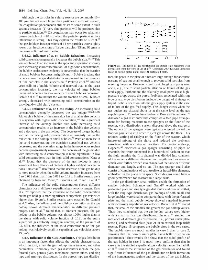
In the gas distributor, small orifices enable the formation ofsmaller bubbles. Schumpe and Grund81 worked with theperforated plate and ring type gas distributor and concluded that,with the ring type distributor, gas holdups of both small andlarge bubbles were smaller compared those with the perforatedplate and the small bubble holdup showed a gradual increasewith increasing superficial gas velocity. Bouaifi et al.147 statedthat, the smaller the bubbles, the greater the gas holdup values.Thus, they concluded that the gas holdup values were higherwith a small orifice gas distributor. Lin et al.94 studied theinfluence of different gas distributors, i.e., porous sinter plate(case 1) and perforated plate (case 2), in an external-loop airliftreactor. Figure 15 compares the bubble sizes in the two cases.The bubble sizes are much smaller in case 1 than in case 2,showing that the porous sinter plate has a better distributionperformance. Their results also show that the radial profile ofthe gas holdup in case 1 is much more uniform than that incase 2 in the studied superficial gas velocity range. Zahradnı´ket al.83 studied the influence of the gas distributor and foundsignificant influences of the gas distributor on both formationof the homogeneous regime and the values of the gas holdup,
Figure 15. Influence of gas distribution on bubble size reprinted withpermission from the work of Lin et al.94 (Copyright 2004 Elsevier Limited):(case 1) porous sinter plate; (case 2) perforated plate.
5834 Ind. Eng. Chem. Res., Vol. 46, No. 18, 2007
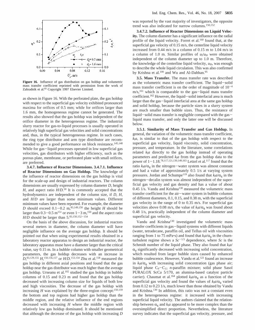
as shown in Figure 16. With the perforated plate, the gas holdupwith respect to the superficial gas velocity exhibited pronouncedmaxima for orifices of 0.5 mm; while for orifices larger than1.6 mm, the homogeneous regime cannot be generated. Theresults also showed that the gas holdup was independent of theorifice diameter in the heterogeneous regime. The industrialslurry reactor for gas-to-liquid processes is usually operated inrelatively high superficial gas velocities and solid concentrationsand, thus, in the typical heterogeneous regime. In such cases,the ring type distributor and arm type distributor are recom-mended to give a good performance on block resistance.145,148
While for gas-liquid processes operated in low superficial gasvelocities, gas distributors with higher efficiency, such as theporous plate, membrane, or perforated plate with small orifices,are preferred.
3.4.7. Influence of Reactor Dimensions. 3.4.7.1. Influenceof Reactor Dimensions on Gas Holdup. The knowledge ofthe influence of reactor dimensions on the gas holdup is vitalfor the scale-up and design of industrial reactors. The columndimensions are usually expressed by column diameterD, heightH, and aspect ratioH/D.50 It is commonly accepted that thehydrodynamics are independent of the column size, ifD, H,and H/D are larger than some minimum values. Differentminimum values have been reported. For example, the diameterD should exceed 0.1-0.2 m,83,149,150the heightH should belarger than 0.3-0.5 m151 or even 1-3 m,150 and the aspect ratioH/D should be larger than 5.83,150,152-154
On the basis of the above discussion, for industrial reactorsseveral meters in diameter, the column diameter will havenegligible influence on the average gas holdup. It should bepointed out that when using experimental results obtained in alaboratory reactor apparatus to design an industrial reactor, thelaboratory apparatus muse have a diameter larger than the criticalvalue, say 0.15 m. In a bubble column with smaller geometricalparameters, the gas holdup decreases with an increase inD,83,129,155H,150,156,157or H/D.153,154Zhu et al.158 measured thegas holdup in different axial positions and found that the gasholdup near the gas distributor was much higher than the averagegas holdup. Urseanu et al.102 studied the gas holdup in bubblecolumns of 0.15 and 0.23 m and found that the gas holdupdecreased with increasing column size for liquids of both lowand high viscosities. The decrease of the gas holdup withincreasingH was explained by the three-region concept:150,159
the bottom and top regions had higher gas holdup than themiddle region, and the relative influence of the end regionsdecreased with increasingH where the middle region withrelatively low gas holdup dominated. It should be mentionedthat although the decrease of the gas holdup with increasingD
was reported by the vast majority of investigators, the oppositetrend was also indicated for narrow columns.150,152
3.4.7.2. Influence of Reactor Dimensions on Liquid Veloc-ity . The column diameter has a significant influence on the radialprofile of the liquid velocity. Forret et al.160 found that, at thesuperficial gas velocity of 0.15 m/s, the centerline liquid velocityincreased from 0.44 m/s in a column of 0.15 m to 1.04 m/s ina column of 1.0 m. Similar profiles oful/ul0 were obtainedindependent of the column diameter up to 1.0 m. Therefore,the knowledge of the centerline liquid velocity,ul0, was enoughto describe the whole liquid circulation. This was also confirmedby Krishna et al.100 and Wu and Al-Dahhan.95
3.5. Mass Transfer.The mass transfer rate was describedas the volumetric mass transfer coefficient. The liquid-solidmass transfer coefficient is on the order of magnitude of 10-4
m/s,161 which is comparable to the gas-liquid mass transfercoefficient.162However, the liquid-solid interfacial area is muchlarger than the gas-liquid interfacial area at the same gas holdupand solid holdup, because the particle sizes in a slurry systemare much smaller than bubble sizes. Thus, the resistance ofliquid-solid mass transfer is negligible compared with the gas-liquid mass transfer, and only the latter one will be discussedbelow.
3.5.1. Similarity of Mass Transfer and Gas Holdup.Ingeneral, the variation of the volumetric mass transfer coefficient,kla, is similar to that of the gas holdup with respect to thesuperficial gas velocity, liquid viscosity, solid concentration,pressure, and temperature. In the literature, some correlationsrelated kla directly to the gas holdup instead of operatingparameters and predictedkla from the gas holdup data to thepower of 1-1.18.78,117,121,130,149,163Letzel et al.117 found that theratio kla/Rg in the nitrogen-water system was almost constantand had a value of approximately 0.5 1/s at varying systempressures. Jordan and Schumpe119 also found thatkla/Rg in thenitrogen-decalin system was almost independent of the super-ficial gas velocity and gas density and has a value of about0.45 1/s. Vandu and Krishna130 measured the volumetric masstransfer coefficient for the air-water system in bubble columnsof different diameters, 0.1, 0.15, and 0.38 m, with the superficialgas velocity in the range of 0 to 0.35 m/s. For superficial gasvelocities above 0.08 m/s, the value ofkla/Rg was found about0.48 1/s, practically independent of the column diameter andsuperficial gas velocity.
Vandu and Krishna130 investigated the volumetric masstransfer coefficients in gas-liquid systems with different liquids(water, tetradecane, paraffin oil, and Tellus oil with viscositiesranging from 1 to 75 mPa‚s) and found thatkla/Rg in the churn-turbulent regime shows aSc-1/3 dependence, whereSc is theSchmidt number of the liquid phase. They also found thatkla/Rg significantly decreased with increasing solid concentration,which resulted from larger bubble sizes caused by enhancedbubble coalescence. However, Vandu et al.121 found an increasein kla/Rg with increasing solid concentration (gas phase air;liquid phase C9-C11 n-paraffin mixture; solid phase SasolPURALOX ScCa 5/170, an alumina-based catalyst particlecarrier). Chaumat et al.164 plotted kla/Rg as a function of thesuperficial gas velocity and found the values ofkla/Rg variedfrom 0.12 to 0.23 1/s, much lower than those obtained by Vanduand Krishna.130 In addition, this ratio was not a constant evenin the heterogeneous regime: it increased with increasingsuperficial liquid velocity. The authors claimed that the relation-ship betweenRg andkla appeared to be more complex than theoversimplified direct proportion. Nevertheless, the literaturesurvey indicates that the superficial gas velocity, pressure, and
Figure 16. Influence of gas distribution on gas holdup and volumetricmass transfer coefficient reprinted with permission from the work ofZahradnı´k et al.83 Copyright 1997 Elsevier Limited.
Ind. Eng. Chem. Res., Vol. 46, No. 18, 20075835
column diameter have insignificant influence onkla/Rg, thuskla/Rg provides a useful scale-up rule, although not strict, forestimatingkla for industrial reactors of large diameter andoperated at high superficial gas velocities and pressures.
3.5.2. Influence of Superficial Gas and Liquid Velocities.The superficial gas velocity is the dominant factor that influenceskla. With increasing superficial gas velocity,kla increases, lesspronounced in the heterogeneous regime than in the homoge-neous regime.19,117-119,121,129,164-166 Tang and Fan167 found thatincreasing the liquid velocity significantly increasedkla but onlyslightly increased the gas holdup. Yang et al.165,166and Chaumatet al.164 found a slight increase inkla with increasing superficialliquid velocity. The enhancement of mass transfer at higherliquid velocities is probably due to the turbulence induced bythe liquid flow. Lau et al.129 found that the influence of theliquid velocity on kla became more pronounced at highpressures. For example, at 2.86 MPa, increasing the liquidvelocity from 0.17 to 0.26 cm/s increased the mass transfercoefficient by as much as 30%.
3.5.3. Influence of Pressure and Temperature.The gasholdup and volumetric mass transfer coefficient increase withincreasing pressure19,117,129,168-171or gas molecular weight.172,173
Kojima et al.169 found that both the gas holdup and volumetricmass transfer coefficient increased with increasing pressure and,for the single-nozzle gas distributor, the influence of the pressureon the gas holdup and volumetric mass transfer coefficientbecame significant at higher superficial gas liquid viscosities.Ozturk et al.172 studied the mass transfer behavior in variousorganic liquids and found that the volumetric mass transfercoefficient increased with increasing gas density. The influenceof temperature on the gas-liquid mass transfer is much morenotable than on the gas holdup, due to the higher liquiddiffusivity at high temperatures. Jordan and Schumpe119 foundthat increasing temperature had little influence on the gasholdups in ethanol and decalin but increased the mass transfercoefficients, mainly, by higher oxygen diffusivity. Lau et al.129
found that kla increases from 0.03 to 0.17 1/s when thetemperature increases from 25 to 92°C. As for the correspond-ing gas holdup, it only increases from 0.24 to 0.30.
3.5.4. Influence of Solid Concentration and Liquid Viscos-ity. Most results in the literature show that the volumetric masstransfer coefficient decreases with increasing solid concentra-tion19,130,149,173,174or liquid viscosity.118,173,175,176However, dif-ferent results were also reported. Vandu et al.121 found that thevolumetric mass transfer coefficient was virtually independentof the solid concentration for the C9-C11 paraffin oil slurrieswith Sasol PURALOX ScCa 5/170 (an alumina-based catalystparticle carrier) as the solid phase. The authors concluded thatthe natures of the solid particles and of the liquid phase wereimportant determinants on the variation of the volumetric masstransfer coefficient with the solid concentration. In somesystems, the volumetric mass transfer coefficient has a maximumvalue in the low-solid-concentration range.165,166,177-179 Thepossible explanation for this is that, in the range of low solidconcentration, the existence and movement of particles take theeffects of breaking bubbles and enhancing the turbulence ofthe liquid phase, which are favorable to intensify the gas-liquidmass transfer. In the range of high solid concentration, theincreased solid concentration results in an increase in theapparent suspension viscosity and a decrease in the gas-liquidmass transfer rate.
3.5.5. Influence of Surfactants.The presence of surfactantsaffects the bubble generation process, hence the specificinterfacial area, liquid-side mass transfer coefficient, and volu-
metric mass transfer coefficient. The influence of surfactantson the gas and liquid mass transfer was rather complex, anddifferent results were reported in the literature. Muller andDavidson180 experimentally studied the effect of surface activeagents on the mass transfer with viscous media and reportedthat the presence of octanol in solution increased the volumetricmass transfer coefficientkla by 50%. The authors attributed thisincrease to the creation of small bubbles and reduced bubblecoalescence due to surfactants. In contrast, different results werereported by some other authors that bothkla and kl valuesmarkedly decreased with the presence of surfactants.181-185
Vazquez et al.182 found a reduction in the interfacial area withthe addition of surfactant; however, Painmanakul et al.,183Azheret al.,184 and Sardeing et al.185 found that the interfacial areasin surfactant solutions were significantly larger than those inwater. Sardeing et al.185 found that the presence of surfactantsdecreased the bubble diameters, and they described three zoneson the variation of the liquid-side mass transfer coefficient withthe bubble diameter: for bubble diameters less than 1.5 mm,thekl values are roughly constant at 1× 10⁻⁴ m/s and no effectof the surfactants was observed; for bubble diameters greaterthan 3.5 mm, thekl values were nearly constant with the bubblediameter but depended on the surfactant concentration; forbubble diameters between 1.5 and 3.5 mm, thekl valuesincreased from 1× 10⁻⁴ m/s to the value reached at 3.5 mmand also depended on the surfactant concentration.
3.5.6. Mass Transfer Coefficient and Interfacial Area.Most studies on the mass transfer behavior are limited todetermining the volumetric mass transfer coefficient,kla.Unfortunately,kla is global and not sufficient to provide a betterunderstanding of the mass transfer mechanism. The separationof kl anda allows to identify which one ofkl anda controls themass transfer.147,166,170
Wilkinson et al.168 found that bothkla anda increased withincreasing pressure in a 0.158 m bubble column using a ringgas distributor with 19 holes of 10 mm. Behkish et al.147
suggested that the gas-liquid mass transfer in the heterogeneousflow regime and high solid concentrations were controlled bythe gas-liquid interfacial area. Stegeman et al.186 studied theinfluence of the superficial gas velocity, pressure, and liquidviscosity on the gas holdup and gas-liquid interfacial area ina bubble column. The reactor was operated at pressures between0.1 and 6.6 MPa, and the gas distributor was a perforated platewith 284 holes of 0.4 mm. The liquid viscosity was varied inthe range from 1.0 to 9.4 mPa‚s. Their results showed that thepressure had a small influence on the gas holdup in pure waterbut had a pronounced influence on the gas holdup for moreviscous liquids. For the most viscous liquid, all interfacial areadata were obtained in the fully heterogeneous regime and it wasdemonstrated that the interfacial area increased with increasingpressure and was moderately affected by the superficial gasvelocity. For the less viscous liquids, both the pressure andsuperficial gas velocity affected the interfacial area and thisinfluence depended on the flow regime. Stegeman et al.186
concluded that the flow regime had an important influence onthe mode in which the operating parameters affected theinterfacial area. Pohorecki et al.187 studied the influences of thetemperature and pressure on the bubble size and gas holdupfor the nitrogen-water system in a temperature range of 30-160°C and a pressure range of 0.1-1.1 MPa. The column wasequipped with several gas distributors of different geometries.The bubble sizes were found to be independent of the positionin the column, distributor geometry, superficial gas velocity,temperature, and pressure. The gas holdup was found to be
5836 Ind. Eng. Chem. Res., Vol. 46, No. 18, 2007
dependent only on the gas superficial velocity. The values ofthe interfacial area, calculated from the experimental values ofthe bubble size and gas holdup, were also found to be dependentonly on the gas velocity. Maalej et al.162 found that, for a givensuperficial gas velocity, bothkla and a increased, whilekl
remained constant whatever the operating pressure; for a fixedgas mass flow rate, bothkla and a decrease with increasingoperating pressure. Yang et al.166 found that both the interfacialarea and mass transfer coefficient increased with increasingsuperficial gas and liquid velocities. They also found thatkl
increased greatly with increasing solid concentration in the low-solid-concentration range and decreased slowly with a furtherincrease in solid holdup. Vandu et al.121 found thatkl for largebubbles was practically independent of the superficial gasvelocity and had values in the range of 0.002-0.003 m/s, about1 order of magnitude higher than those estimated from thecorrelation proposed by Akita and Yoshida.78 This higherkl
value can be attributed to the frequent bubble breakup andcoalescence of large bubbles, which enhance the renewal of thegas-liquid interface. Lemoine115 studied the hydrodynamic andmass transfer characteristics in organic liquid mixtures in a large-scale bubble column for the toluene oxidation process. Theyfound that bothkl anda increased with increasing superficialgas velocity. Increasing pressure, on the other hand, increasedboth kla anda but decreasedkl.
3.6. Liquid-Solid Separation. In FT synthesis in a slurryreactor, it is necessary to maintain the slurry at a constant level,removing the liquid products from the reactor. One problemwith the removal of liquids, however, is that catalyst particlesare dispersed in the liquid and must be separated from the slurryand, in some cases, returned to the reactor in order to maintaina constant inventory of catalyst in the reactor. Both iron catalystand cobalt catalyst are currently used for FT synthesis. Separa-tion of wax from supported cobalt catalysts is much easier thanfor unsupported iron catalysts due to attrition resistance of thesupport material.11 The unsupported iron catalyst will be rapidlybroken down to produce fine particles of 1-3 µm,188 whichfurther increases the difficulty of the liquid-solid separation,for example, blinds the pore openings of the filter. To solveproblems with solid separation from the liquid products, Sasolpaid attention both to physical characteristics of the catalystand the separation processes themselves. Several techniqueswere evaluated; these findings were considered to be proprietaryinformation. Stringent specifications for solids in the final waxcut were claimed to have been easily met.17
In general, there are two types of liquid-solid separators:in-reactor separators and external separators. A comprehensivereview of the liquid-solid separation for the FT synthesisprocess was given by Zhou and Srivastava,189 in which theliquid-solid separation approaches were divided into filtration,settling, centrifugation, vacuum distillation plus thermal crack-ing, high gradient magnetic separation, and chemical conversion.It was concluded that gravity settling, centrifugation, pressurefiltration, and high gradient magnetic separation were technicallyfeasible, either singly or in combination. In this section, recentdevelopments on the liquid-solid separation for a slurry systemwill be reviewed.
3.6.1. Settling Method.Gravity settling is a commonly used,simple, and inexpensive method for FT wax-catalyst separation,but a long settling time of 1-3 h is required to reduce the solidscontent in the wax to 0.1 wt %. Zhou and Srivastava189 reportedthat the British Greenwich FT pilot plant operated a gravitysettling system fairly well. Mobil utilized an external systemin which slurry was circulated by density differences and the
time in the separator was sufficient for the slurry to settle sothat solids-rich and nearly solids-free zones were formed. It maybe difficult to achieve very low solids content, e.g., 1-2 ppm,for the wax by means of settlers and hydroclones. However,they can be a good preliminary separation step to recover mostof the catalyst particles from the slurry in the form of aconcentrated catalyst underflow for recycling back to the reactor.The clarified wax overflow can subsequently be processed bymore efficient but usually expensive techniques, such as pressurefiltration and magnetic separation to required low solid content.
Benham et al.190 disclosed a dynamic settler apparatus forwax-catalyst separation. The settler has a sealed chamber intowhich a vertical feed conduit extends downward for a substantiallength so as to form an annular region between the inner wallsof the chamber and the feed conduit. As the slurry flows intothe annular region at the bottom of the settler, the heaviercatalyst particles are carried down, removed from the settler atthe bottom, and then recycled back to the reactor. The wax risesup in the annular region, and this clarified wax is removed atthe top. In this dynamic settler apparatus, both gravity and thejet momentum cause the particles to move downward. The outletpipe for clarified wax can optionally have a filter to furtherpurify the wax. Both internal and external dynamic settlers canbe used in series to further improve the wax-catalyst separationefficiency.
Hydroclones have been successfully employed for the liquid-solid separation in the petroleum refining industry and, recently,have been used in the FT synthesis process. Clerici andBelmonte191 disclosed using hydroclones coupled with a porousfilter for the liquid-solid separation for the FT synthesis process.The hydrocyclone separates the suspension into the underflowconcentrated in solids and the overflow diluted in solids. Thediluted overflow is further separated by the micro-/ultrafiltrationelement to give the liquid product.
3.6.2. Filtration Method. Rytter et al.192 described a verticalcylindrical filter in the form of a fine meshed screen locatedinside the reactor within the slurry. In the examples, modelswere used for the separation rather than a working reactor. Sasoldescribed in some detail their operation in a large pilot plantwith a slurry bubble column using a filter.193 Anderson194
disclosed a method in which the liquid product is separated fromthe catalyst particles by passing the liquid product through aplurality of cylindrical filters located within the reactor, suchthat the liquid passes through the filters and the catalyst particlesconglomerate on the outside of the filters. As the liquid productis removed from the filters, a portion of it is pumped into apulse surge vessel, such that the pressure of the pulse surgevessel is higher than the pressure of the FT reactor. At the timethat it is desirable to remove the conglomerated catalyst on thefilters, the liquid product through the filters is stopped and ahigh-pressure liquid product is sent from the pulse surge vesselto a back-flushing liquid inlet of the filter to dislodge theconglomerated catalyst particles. Mu¨ller195 reported using theFUNDABAC filter family for liquid-solid separation. In theFUNDABAC filtration system, each element is composed ofsix filter tubes that were arranged around a central filtrate tube.This created a so-called clover leaf pattern in cross section. Thisunusual design promoted good adherence of the filter cake tothe filter cloth, i.e., the concave areas of the filter element causedthe cake to adhere during compression and guaranteed that itremained in place throughout the entire cycle.
3.6.3. Other Liquid-Solid Separation Methods. 3.6.3.1.Extraction . The U.S. DOE patented a process that separatesthe catalyst from the wax product using a dense gas and/or liquid
Ind. Eng. Chem. Res., Vol. 46, No. 18, 20075837
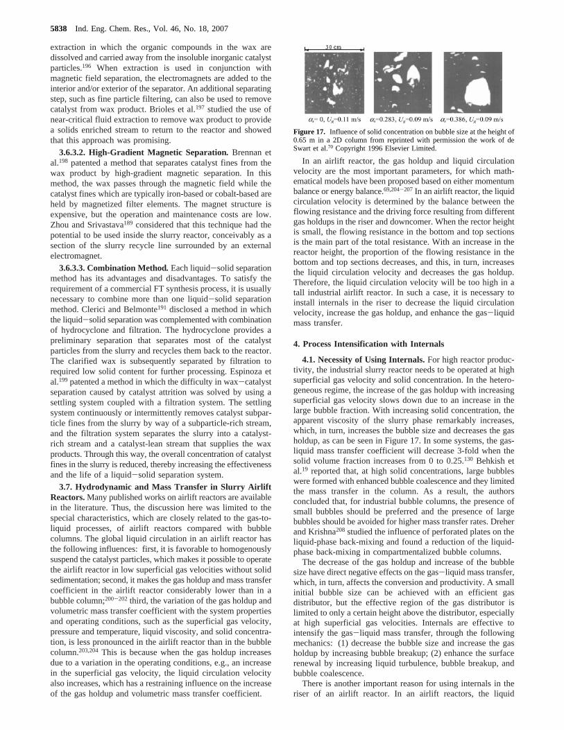
extraction in which the organic compounds in the wax aredissolved and carried away from the insoluble inorganic catalystparticles.196 When extraction is used in conjunction withmagnetic field separation, the electromagnets are added to theinterior and/or exterior of the separator. An additional separatingstep, such as fine particle filtering, can also be used to removecatalyst from wax product. Brioles et al.197 studied the use ofnear-critical fluid extraction to remove wax product to providea solids enriched stream to return to the reactor and showedthat this approach was promising.
3.6.3.2. High-Gradient Magnetic Separation. Brennan etal.198 patented a method that separates catalyst fines from thewax product by high-gradient magnetic separation. In thismethod, the wax passes through the magnetic field while thecatalyst fines which are typically iron-based or cobalt-based areheld by magnetized filter elements. The magnet structure isexpensive, but the operation and maintenance costs are low.Zhou and Srivastava189 considered that this technique had thepotential to be used inside the slurry reactor, conceivably as asection of the slurry recycle line surrounded by an externalelectromagnet.
3.6.3.3. Combination Method. Each liquid-solid separationmethod has its advantages and disadvantages. To satisfy therequirement of a commercial FT synthesis process, it is usuallynecessary to combine more than one liquid-solid separationmethod. Clerici and Belmonte191 disclosed a method in whichthe liquid-solid separation was complemented with combinationof hydrocyclone and filtration. The hydrocyclone provides apreliminary separation that separates most of the catalystparticles from the slurry and recycles them back to the reactor.The clarified wax is subsequently separated by filtration torequired low solid content for further processing. Espinoza etal.199 patented a method in which the difficulty in wax-catalystseparation caused by catalyst attrition was solved by using asettling system coupled with a filtration system. The settlingsystem continuously or intermittently removes catalyst subpar-ticle fines from the slurry by way of a subparticle-rich stream,and the filtration system separates the slurry into a catalyst-rich stream and a catalyst-lean stream that supplies the waxproducts. Through this way, the overall concentration of catalystfines in the slurry is reduced, thereby increasing the effectivenessand the life of a liquid-solid separation system.
3.7. Hydrodynamic and Mass Transfer in Slurry AirliftReactors.Many published works on airlift reactors are availablein the literature. Thus, the discussion here was limited to thespecial characteristics, which are closely related to the gas-to-liquid processes, of airlift reactors compared with bubblecolumns. The global liquid circulation in an airlift reactor hasthe following influences: first, it is favorable to homogenouslysuspend the catalyst particles, which makes it possible to operatethe airlift reactor in low superficial gas velocities without solidsedimentation; second, it makes the gas holdup and mass transfercoefficient in the airlift reactor considerably lower than in abubble column;200-202 third, the variation of the gas holdup andvolumetric mass transfer coefficient with the system propertiesand operating conditions, such as the superficial gas velocity,pressure and temperature, liquid viscosity, and solid concentra-tion, is less pronounced in the airlift reactor than in the bubblecolumn.203,204 This is because when the gas holdup increasesdue to a variation in the operating conditions, e.g., an increasein the superficial gas velocity, the liquid circulation velocityalso increases, which has a restraining influence on the increaseof the gas holdup and volumetric mass transfer coefficient.
In an airlift reactor, the gas holdup and liquid circulationvelocity are the most important parameters, for which math-ematical models have been proposed based on either momentumbalance or energy balance.69,204-207 In an airlift reactor, the liquidcirculation velocity is determined by the balance between theflowing resistance and the driving force resulting from differentgas holdups in the riser and downcomer. When the rector heightis small, the flowing resistance in the bottom and top sectionsis the main part of the total resistance. With an increase in thereactor height, the proportion of the flowing resistance in thebottom and top sections decreases, and this, in turn, increasesthe liquid circulation velocity and decreases the gas holdup.Therefore, the liquid circulation velocity will be too high in atall industrial airlift reactor. In such a case, it is necessary toinstall internals in the riser to decrease the liquid circulationvelocity, increase the gas holdup, and enhance the gas-liquidmass transfer.
4. Process Intensification with Internals
4.1. Necessity of Using Internals.For high reactor produc-tivity, the industrial slurry reactor needs to be operated at highsuperficial gas velocity and solid concentration. In the hetero-geneous regime, the increase of the gas holdup with increasingsuperficial gas velocity slows down due to an increase in thelarge bubble fraction. With increasing solid concentration, theapparent viscosity of the slurry phase remarkably increases,which, in turn, increases the bubble size and decreases the gasholdup, as can be seen in Figure 17. In some systems, the gas-liquid mass transfer coefficient will decrease 3-fold when thesolid volume fraction increases from 0 to 0.25.130 Behkish etal.19 reported that, at high solid concentrations, large bubbleswere formed with enhanced bubble coalescence and they limitedthe mass transfer in the column. As a result, the authorsconcluded that, for industrial bubble columns, the presence ofsmall bubbles should be preferred and the presence of largebubbles should be avoided for higher mass transfer rates. Dreherand Krishna208 studied the influence of perforated plates on theliquid-phase back-mixing and found a reduction of the liquid-phase back-mixing in compartmentalized bubble columns.
The decrease of the gas holdup and increase of the bubblesize have direct negative effects on the gas-liquid mass transfer,which, in turn, affects the conversion and productivity. A smallinitial bubble size can be achieved with an efficient gasdistributor, but the effective region of the gas distributor islimited to only a certain height above the distributor, especiallyat high superficial gas velocities. Internals are effective tointensify the gas-liquid mass transfer, through the followingmechanics: (1) decrease the bubble size and increase the gasholdup by increasing bubble breakup; (2) enhance the surfacerenewal by increasing liquid turbulence, bubble breakup, andbubble coalescence.
There is another important reason for using internals in theriser of an airlift reactor. In an airlift reactors, the liquid
Figure 17. Influence of solid concentration on bubble size at the height of0.65 m in a 2D column from reprinted with permission the work of deSwart et al.70 Copyright 1996 Elsevier Limited.
5838 Ind. Eng. Chem. Res., Vol. 46, No. 18, 2007
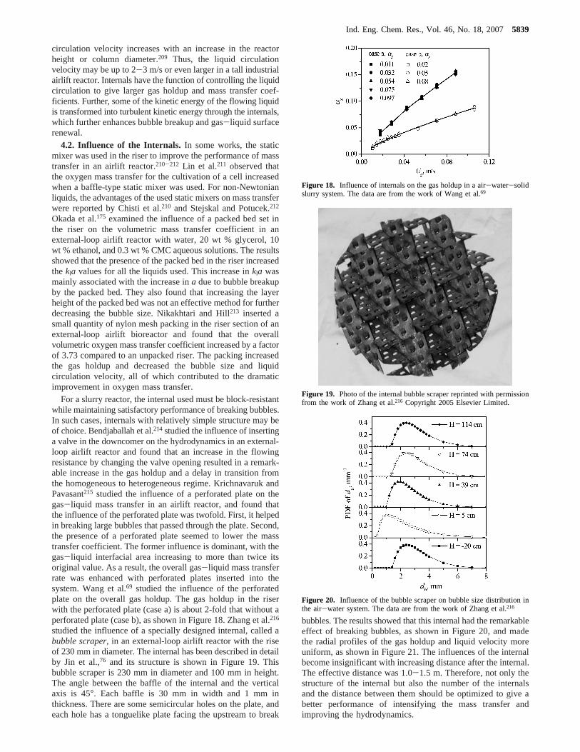
circulation velocity increases with an increase in the reactorheight or column diameter.209 Thus, the liquid circulationvelocity may be up to 2-3 m/s or even larger in a tall industrialairlift reactor. Internals have the function of controlling the liquidcirculation to give larger gas holdup and mass transfer coef-ficients. Further, some of the kinetic energy of the flowing liquidis transformed into turbulent kinetic energy through the internals,which further enhances bubble breakup and gas-liquid surfacerenewal.
4.2. Influence of the Internals. In some works, the staticmixer was used in the riser to improve the performance of masstransfer in an airlift reactor.210-212 Lin et al.211 observed thatthe oxygen mass transfer for the cultivation of a cell increasedwhen a baffle-type static mixer was used. For non-Newtonianliquids, the advantages of the used static mixers on mass transferwere reported by Chisti et al.210 and Stejskal and Potucek.212
Okada et al.175 examined the influence of a packed bed set inthe riser on the volumetric mass transfer coefficient in anexternal-loop airlift reactor with water, 20 wt % glycerol, 10wt % ethanol, and 0.3 wt % CMC aqueous solutions. The resultsshowed that the presence of the packed bed in the riser increasedthekla values for all the liquids used. This increase inkla wasmainly associated with the increase ina due to bubble breakupby the packed bed. They also found that increasing the layerheight of the packed bed was not an effective method for furtherdecreasing the bubble size. Nikakhtari and Hill213 inserted asmall quantity of nylon mesh packing in the riser section of anexternal-loop airlift bioreactor and found that the overallvolumetric oxygen mass transfer coefficient increased by a factorof 3.73 compared to an unpacked riser. The packing increasedthe gas holdup and decreased the bubble size and liquidcirculation velocity, all of which contributed to the dramaticimprovement in oxygen mass transfer.
For a slurry reactor, the internal used must be block-resistantwhile maintaining satisfactory performance of breaking bubbles.In such cases, internals with relatively simple structure may beof choice. Bendjaballah et al.214studied the influence of insertinga valve in the downcomer on the hydrodynamics in an external-loop airlift reactor and found that an increase in the flowingresistance by changing the valve opening resulted in a remark-able increase in the gas holdup and a delay in transition fromthe homogeneous to heterogeneous regime. Krichnavaruk andPavasant215 studied the influence of a perforated plate on thegas-liquid mass transfer in an airlift reactor, and found thatthe influence of the perforated plate was twofold. First, it helpedin breaking large bubbles that passed through the plate. Second,the presence of a perforated plate seemed to lower the masstransfer coefficient. The former influence is dominant, with thegas-liquid interfacial area increasing to more than twice itsoriginal value. As a result, the overall gas-liquid mass transferrate was enhanced with perforated plates inserted into thesystem. Wang et al.69 studied the influence of the perforatedplate on the overall gas holdup. The gas holdup in the riserwith the perforated plate (case a) is about 2-fold that without aperforated plate (case b), as shown in Figure 18. Zhang et al.216
studied the influence of a specially designed internal, called abubble scraper, in an external-loop airlift reactor with the riseof 230 mm in diameter. The internal has been described in detailby Jin et al.,76 and its structure is shown in Figure 19. Thisbubble scraper is 230 mm in diameter and 100 mm in height.The angle between the baffle of the internal and the verticalaxis is 45°. Each baffle is 30 mm in width and 1 mm inthickness. There are some semicircular holes on the plate, andeach hole has a tonguelike plate facing the upstream to break
bubbles. The results showed that this internal had the remarkableeffect of breaking bubbles, as shown in Figure 20, and madethe radial profiles of the gas holdup and liquid velocity moreuniform, as shown in Figure 21. The influences of the internalbecome insignificant with increasing distance after the internal.The effective distance was 1.0-1.5 m. Therefore, not only thestructure of the internal but also the number of the internalsand the distance between them should be optimized to give abetter performance of intensifying the mass transfer andimproving the hydrodynamics.
Figure 18. Influence of internals on the gas holdup in a air-water-solidslurry system. The data are from the work of Wang et al.69
Figure 19. Photo of the internal bubble scraper reprinted with permissionfrom the work of Zhang et al.216 Copyright 2005 Elsevier Limited.
Figure 20. Influence of the bubble scraper on bubble size distribution inthe air-water system. The data are from the work of Zhang et al.216
Ind. Eng. Chem. Res., Vol. 46, No. 18, 20075839
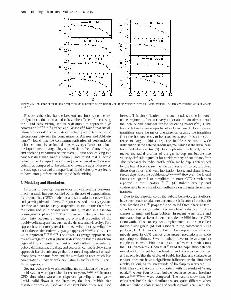
Besides enhancing bubble breakup and improving the hy-drodynamics, the internals also have the effects of decreasingthe liquid back-mixing, which is desirable to approach highconversion.208,217-219 Dreher and Krishna208 found that instal-lation of perforated sieve plates effectively restricted the liquidcirculations between the compartments. Alvare´a and Al-Dah-hanb219 found that the compartmentalization of conventionalbubble columns by perforated trays was very effective to reducethe liquid back-mixing. They studied the effect of tray designand operating conditions on the overall liquid back-mixing in abench-scale trayed bubble column and found that a 3-foldreduction in the liquid back-mixing was achieved in the trayedcolumn as compared to the column without the trays. Moreover,the tray open area and the superficial liquid velocity were foundto have strong effects on the liquid back-mixing.
5. Modeling and Simulations
In order to develop design tools for engineering purposes,much research has been carried out in the area of computationalfluid dynamics (CFD) modeling and simulation on gas-liquidand gas-liquid-solid flows. The particles used in slurry systemsare fine and can be easily suspended in the liquid; therefore,the liquid and solid phases were usually treated as a pseudo-homogeneous phase.84,220 The influence of the particles wastaken into account by using the physical properties of theliquid-solid suspension, such as the density and viscosity. Twoapproaches are mostly used in the gas-liquid or gas-liquid-solid flows: the Euler-Lagrange approach221,222 and Euler-Euler approach.73,88,223,224The Euler-Lagrange approach hasthe advantage of a clear physical description but the disadvan-tages of high computational cost and difficulties in consideringbubble deformation, breakup, and coalescence. The Euler-Eulerapproach has the advantage that the model equations for eachphase have the same form and the simulations need much lesscomputations. Reactor-scale simulations usually use the Euler-Euler approach.
Several good reviews on modeling and simulation of the gas-liquid system were published in recent years.15,225-227 In mostCFD simulation works on dispersed gas-liquid and gas-liquid-solid flows in the literature, the local bubble sizedistribution was not used and a constant bubble size was used
instead. This simplification limits such models to the homoge-neous regime. In fact, it is very important to consider in detailthe local bubble behavior for the following reasons:74 (1) Thebubble behavior has a significant influence on the flow regimetransition, since the major phenomenon causing the transitionfrom the homogeneous to heterogeneous regime is the occur-rence of large bubbles. (2) The bubble size has a widedistribution in the heterogeneous regime, which is the usual casefor an industrial reactor. (3) The complexity of bubble dynamicsmakes the radial profiles of the gas holdup and bubble risevelocity difficult to predict for a wide variety of conditions.15,225
This is because the radial profile of the gas holdup is determinedby the lateral forces, such as the transverse lift force, turbulentdispersion force, and wall lubrication force, and these lateralforces depend on the bubble size.84,92,93,228However, the lateralforces are ignored or simplified in most CFD simulationsreported in the literature.229-231 (4) Bubble breakup andcoalescence have a significant influence on the interphase masstransfer.
Due to the importance of the bubble behavior, great effortshave been made to take into account the influence of the bubblesize. Krishna et al.91 proposed a so-called three-phase or two-class bubble model, in which the gas phase is divided into twoclasses of small and large bubbles. In recent years, more andmore attention has been drawn to couple the PBM into the CFDframework. This concept was implemented as the so-calledmultiple-size-group (MUSIG) model in the commercial CFDpackage, CFX. However the bubble breakup and coalescencemodels used in CFX cannot give proper predictions in wideoperating conditions. Several authors have made attempts tocouple their own bubble breakup and coalescence models intothe CFD framework. Chen et al.75 used the population balancemodel with different bubble breakup and coalescence closuresand concluded that the choice of bubble breakup and coalescenceclosure does not have a significant influence on the simulatedresults as long as the magnitude of breakup is increased 10-fold. This conclusion is not consistent with the results of Wanget al.,63 where four typical bubble coalescence and breakupmodes48,58-60,62,73 were compared. The results show that thecalculated bubble size distributions are quite different whendifferent bubble coalescence and breakup models are used. The
Figure 21. Influence of the bubble scraper on radial profiles of gas holdup and liquid velocity in the air-water system. The data are from the work of Zhanget al.216
5840 Ind. Eng. Chem. Res., Vol. 46, No. 18, 2007
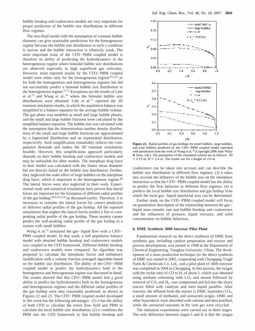
bubble breakup and coalescence models are very important forproper prediction of the bubble size distributions in differentflow regimes.
The two-fluid model with the assumption of constant bubblediameter can give reasonable predictions for the homogeneousregime because the bubble size distribution in such a conditionis narrow and the bubble interaction is relatively weak. Themost important issue of the CFD-PBM coupled model istherefore its ability of predicting the hydrodynamics in theheterogeneous regime where bimodal bubble size distributionsare observed especially in high superficial gas velocities.However, most reported results by the CFD-PBM coupledmodel were either only for the homogeneous regime232,233 orfor both the homogeneous and heterogeneous regimes but didnot successfully predict a bimodal bubble size distribution inthe heterogeneous regime.57,75Exceptions are the results of Lehret al.73 and Wang et al.,74 where the bimodal bubble sizedistributions were obtained. Lehr et al.73 reported the 3Dtransient simulation results, in which the population balance wassimplified to a balance equation for the average bubble volume.The gas phase was modeled as small and large bubble phases,and the small and large bubble fractions were calculated by thesimplified balance equation. The bubble size was calculated withthe assumption that the dimensionless number density distribu-tions of the small and large bubble fractions are approximatedby a lognormal distribution and an exponential distribution,respectively. Such simplification remarkably reduces the com-putation demands and makes the 3D transient simulationsfeasible. However, this simplification approach particularlydepends on their bubble breakup and coalescence models andmay be unfeasible for other models. The interphase drag forcein their model was calculated with the Sauter mean diameterbut not directly based on the bubble size distribution. Further,they neglected the wake effect of large bubbles on the interphasedrag force, which is important in the heterogeneous regime.88
The lateral forces were also neglected in their work. Experi-mental study and numerical simulations have proven that lateralforces are important for the formation of different radial profilesof the gas holdup,84,92,93,234as discussed earlier. Therefore, it isnecessary to consider the lateral forces for correct predictionof different radial profiles of the gas holdup. All the reportedsimulations that neglect the lateral forces predict a flat or core-peaking radial profile of the gas holdup. These models cannotpredict the wall-peaking radial profile of the gas holdup in asystem with small bubbles.
Wang et al.74 simulated the gas-liquid flow with a CFD-PBM coupled model. In that work, a full population balancemodel with detailed bubble breakup and coalescence modelswas coupled in the CFD framework. Different bubble breakupand coalescence models were compared. An algorithm wasproposed to calculate the interphase forces and turbulencemodification with a volume fraction averaged algorithm basedon the bubble size distribution. The ability of the CFD-PBMcoupled model to predict the hydrodynamics both in thehomogeneous and heterogeneous regime was discussed in detail.The results showed that this CFD-PBM model had a goodability to predict the hydrodynamics both in the homogeneousand heterogeneous regimes and the different radial profiles ofthe gas holdup were also reasonably predicted, as shown inFigures 22 and 23. The CFD-PBM coupled model developedin this work has the following advantages: (1) it has the abilityof both CFD to calculate the entire flow field and PBM tocalculate the local bubble size distribution; (2) it combines thePBM into the CFD framework so that bubble breakup and
coalescence can be taken into account and can describe thebubble size distribution in different flow regimes; (3) it takesinto account the influence of the bubble size on the interphaseinteraction so that the CFD-PBM coupled model has the abilityto predict the flow behavior in different flow regimes; (4) itpredicts the local bubble size distribution and gas holdup fromwhich the local gas-liquid interfacial area can be determined.
Further study on the CFD-PBM coupled model will focuson quantitative description of the relationship between the gas-liquid mass transfer rate and bubble breakup and coalescenceand the influences of pressure, liquid viscosity, and solidconcentration on bubble behaviors.
6. DME Synthesis 3000 ton/year Pilot Plant
Fundamental research on the direct synthesis of DME fromsynthesis gas, including catalyst preparation and reactor andprocess development, was started in 1998 at the Department ofChemical Engineering, Tsinghua University, China. The devel-opment of a mass production technique for the direct synthesisof DME was started in 2002, cooperating with Chongqing YingliFuels & Chemicals Co. Ltd., and a pilot plant of 3000 ton/yearwas completed in 2004 in Chongqing. In this process, the syngaswith the molar ratio of CO to H2 of about 1, which was obtainedusing methane reforming with CO2 and stream followed byremoval of CO2 and H2, was compressed and fed into the slurryreactor filled with catalysts and inert liquid paraffin. Afterreaction, the effluent from the reactor is DME, byproduct CO2,a small amount of methanol, and unreacted syngas. DME andother byproducts were absorbed with solvent and then purified,while the unreacted reactants in the vent gas were recycled.
The industrial experiments were carried out in three stages.The only difference between stages I and II is that the syngas
Figure 22. Radial profiles of gas holdups for small bubbles, large bubbles,and total bubbles predicted by the CFD-PBM coupled model reprintedwith permission from the work of Wang et al.74 (Copyright 2006 John Wiley& Sons, Ldt.). The parameters of the simulated column are as follows: ID) 0.19 m,H ) 2.4 m. The results are for a height of 2.0 m.
Ind. Eng. Chem. Res., Vol. 46, No. 18, 20075841
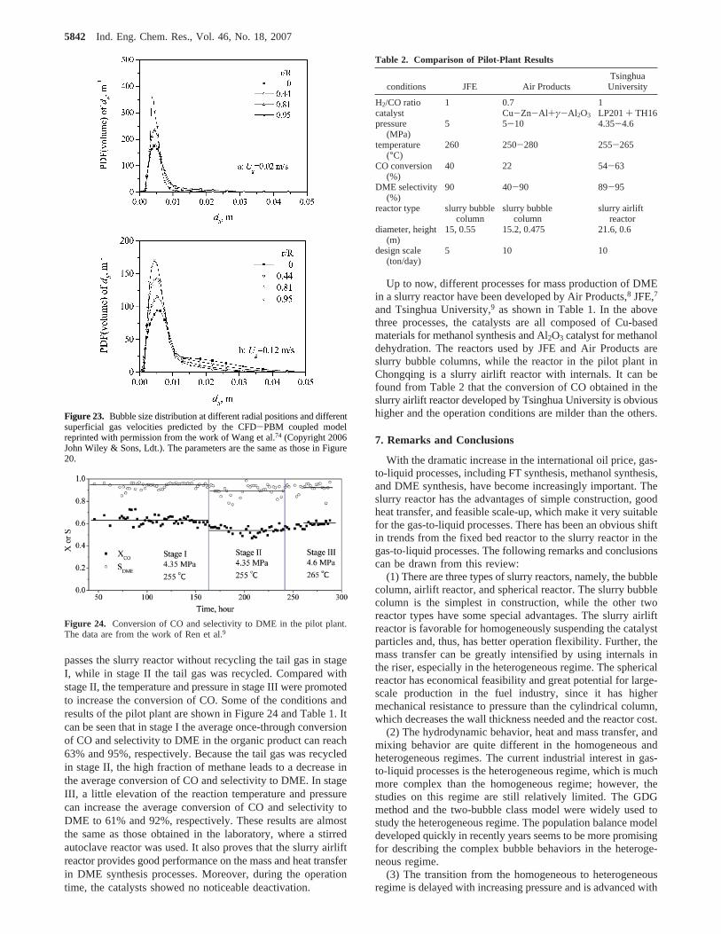
passes the slurry reactor without recycling the tail gas in stageI, while in stage II the tail gas was recycled. Compared withstage II, the temperature and pressure in stage III were promotedto increase the conversion of CO. Some of the conditions andresults of the pilot plant are shown in Figure 24 and Table 1. Itcan be seen that in stage I the average once-through conversionof CO and selectivity to DME in the organic product can reach63% and 95%, respectively. Because the tail gas was recycledin stage II, the high fraction of methane leads to a decrease inthe average conversion of CO and selectivity to DME. In stageIII, a little elevation of the reaction temperature and pressurecan increase the average conversion of CO and selectivity toDME to 61% and 92%, respectively. These results are almostthe same as those obtained in the laboratory, where a stirredautoclave reactor was used. It also proves that the slurry airliftreactor provides good performance on the mass and heat transferin DME synthesis processes. Moreover, during the operationtime, the catalysts showed no noticeable deactivation.
Up to now, different processes for mass production of DMEin a slurry reactor have been developed by Air Products,8 JFE,7
and Tsinghua University,9 as shown in Table 1. In the abovethree processes, the catalysts are all composed of Cu-basedmaterials for methanol synthesis and Al2O3 catalyst for methanoldehydration. The reactors used by JFE and Air Products areslurry bubble columns, while the reactor in the pilot plant inChongqing is a slurry airlift reactor with internals. It can befound from Table 2 that the conversion of CO obtained in theslurry airlift reactor developed by Tsinghua University is obvioushigher and the operation conditions are milder than the others.
7. Remarks and Conclusions
With the dramatic increase in the international oil price, gas-to-liquid processes, including FT synthesis, methanol synthesis,and DME synthesis, have become increasingly important. Theslurry reactor has the advantages of simple construction, goodheat transfer, and feasible scale-up, which make it very suitablefor the gas-to-liquid processes. There has been an obvious shiftin trends from the fixed bed reactor to the slurry reactor in thegas-to-liquid processes. The following remarks and conclusionscan be drawn from this review:
(1) There are three types of slurry reactors, namely, the bubblecolumn, airlift reactor, and spherical reactor. The slurry bubblecolumn is the simplest in construction, while the other tworeactor types have some special advantages. The slurry airliftreactor is favorable for homogeneously suspending the catalystparticles and, thus, has better operation flexibility. Further, themass transfer can be greatly intensified by using internals inthe riser, especially in the heterogeneous regime. The sphericalreactor has economical feasibility and great potential for large-scale production in the fuel industry, since it has highermechanical resistance to pressure than the cylindrical column,which decreases the wall thickness needed and the reactor cost.
(2) The hydrodynamic behavior, heat and mass transfer, andmixing behavior are quite different in the homogeneous andheterogeneous regimes. The current industrial interest in gas-to-liquid processes is the heterogeneous regime, which is muchmore complex than the homogeneous regime; however, thestudies on this regime are still relatively limited. The GDGmethod and the two-bubble class model were widely used tostudy the heterogeneous regime. The population balance modeldeveloped quickly in recently years seems to be more promisingfor describing the complex bubble behaviors in the heteroge-neous regime.
(3) The transition from the homogeneous to heterogeneousregime is delayed with increasing pressure and is advanced with
Figure 23. Bubble size distribution at different radial positions and differentsuperficial gas velocities predicted by the CFD-PBM coupled modelreprinted with permission from the work of Wang et al.74 (Copyright 2006John Wiley & Sons, Ldt.). The parameters are the same as those in Figure20.
Figure 24. Conversion of CO and selectivity to DME in the pilot plant.The data are from the work of Ren et al.9
Table 2. Comparison of Pilot-Plant Results
conditions JFE Air ProductsTsinghuaUniversity
H2/CO ratio 1 0.7 1catalyst Cu-Zn-Al+γ-Al2O3 LP201+ TH16pressure
(MPa)5 5-10 4.35-4.6
temperature(°C)
260 250-280 255-265
CO conversion(%)
40 22 54-63
DME selectivity(%)
90 40-90 89-95
reactor type slurry bubblecolumn
slurry bubblecolumn
slurry airliftreactor
diameter, height(m)
15, 0.55 15.2, 0.475 21.6, 0.6
design scale(ton/day)
5 10 10
5842 Ind. Eng. Chem. Res., Vol. 46, No. 18, 2007
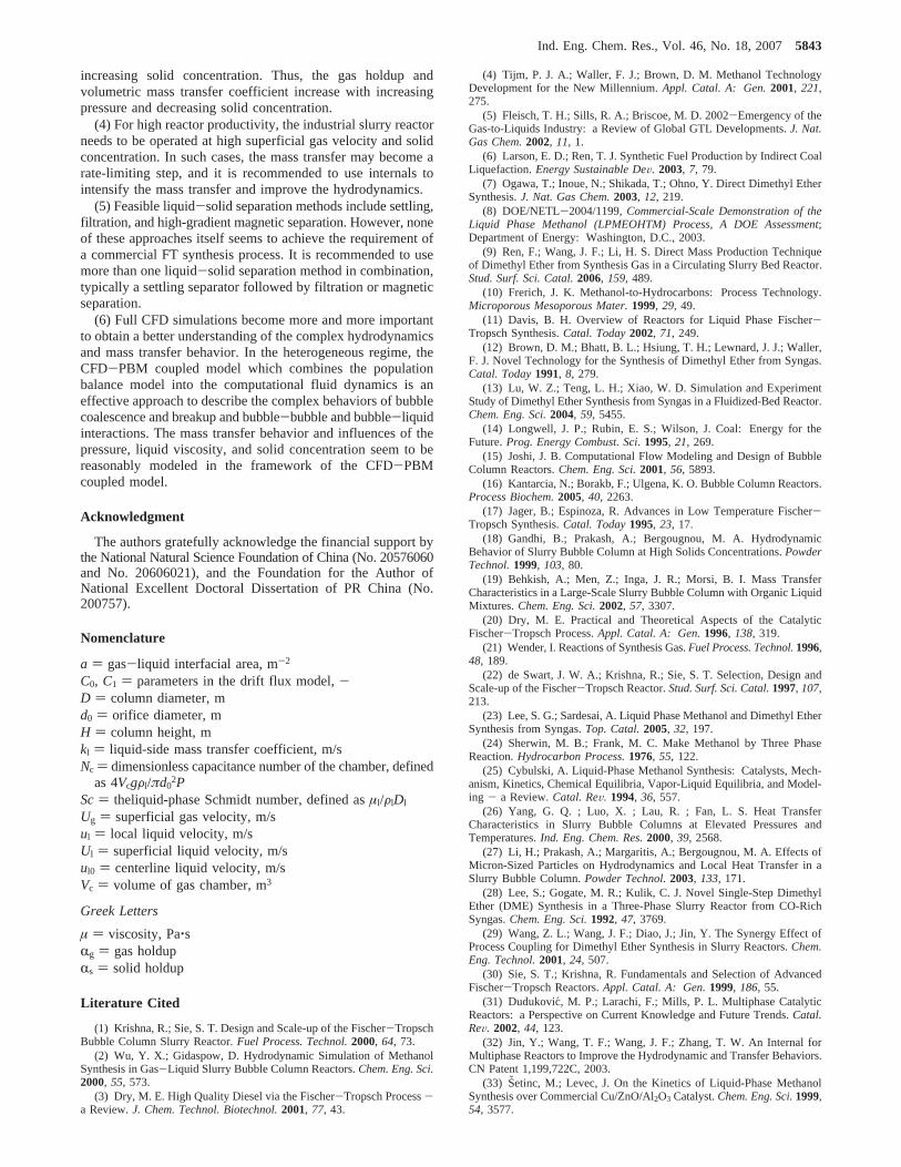
increasing solid concentration. Thus, the gas holdup andvolumetric mass transfer coefficient increase with increasingpressure and decreasing solid concentration.
(4) For high reactor productivity, the industrial slurry reactorneeds to be operated at high superficial gas velocity and solidconcentration. In such cases, the mass transfer may become arate-limiting step, and it is recommended to use internals tointensify the mass transfer and improve the hydrodynamics.
(5) Feasible liquid-solid separation methods include settling,filtration, and high-gradient magnetic separation. However, noneof these approaches itself seems to achieve the requirement ofa commercial FT synthesis process. It is recommended to usemore than one liquid-solid separation method in combination,typically a settling separator followed by filtration or magneticseparation.
(6) Full CFD simulations become more and more importantto obtain a better understanding of the complex hydrodynamicsand mass transfer behavior. In the heterogeneous regime, theCFD-PBM coupled model which combines the populationbalance model into the computational fluid dynamics is aneffective approach to describe the complex behaviors of bubblecoalescence and breakup and bubble-bubble and bubble-liquidinteractions. The mass transfer behavior and influences of thepressure, liquid viscosity, and solid concentration seem to bereasonably modeled in the framework of the CFD-PBMcoupled model.
Acknowledgment
The authors gratefully acknowledge the financial support bythe National Natural Science Foundation of China (No. 20576060and No. 20606021), and the Foundation for the Author ofNational Excellent Doctoral Dissertation of PR China (No.200757).
Nomenclature
a ) gas-liquid interfacial area, m-2
C0, C1 ) parameters in the drift flux model,-D ) column diameter, md0 ) orifice diameter, mH ) column height, mkl ) liquid-side mass transfer coefficient, m/sNc ) dimensionless capacitance number of the chamber, defined
as 4VcgFl/πd02P
Sc) theliquid-phase Schmidt number, defined asµl/FlDl
Ug ) superficial gas velocity, m/sul ) local liquid velocity, m/sUl ) superficial liquid velocity, m/sul0 ) centerline liquid velocity, m/sVc ) volume of gas chamber, m3
Greek Letters
µ ) viscosity, Pa‚sRg ) gas holdupRs ) solid holdup
Literature Cited
(1) Krishna, R.; Sie, S. T. Design and Scale-up of the Fischer-TropschBubble Column Slurry Reactor.Fuel Process. Technol.2000, 64, 73.
(2) Wu, Y. X.; Gidaspow, D. Hydrodynamic Simulation of MethanolSynthesis in Gas-Liquid Slurry Bubble Column Reactors.Chem. Eng. Sci.2000, 55, 573.
(3) Dry, M. E. High Quality Diesel via the Fischer-Tropsch Process-a Review.J. Chem. Technol. Biotechnol.2001, 77, 43.
(4) Tijm, P. J. A.; Waller, F. J.; Brown, D. M. Methanol TechnologyDevelopment for the New Millennium.Appl. Catal. A: Gen.2001, 221,275.
(5) Fleisch, T. H.; Sills, R. A.; Briscoe, M. D. 2002-Emergency of theGas-to-Liquids Industry: a Review of Global GTL Developments.J. Nat.Gas Chem.2002, 11, 1.
(6) Larson, E. D.; Ren, T. J. Synthetic Fuel Production by Indirect CoalLiquefaction.Energy Sustainable DeV. 2003, 7, 79.
(7) Ogawa, T.; Inoue, N.; Shikada, T.; Ohno, Y. Direct Dimethyl EtherSynthesis.J. Nat. Gas Chem.2003, 12, 219.
(8) DOE/NETL-2004/1199,Commercial-Scale Demonstration of theLiquid Phase Methanol (LPMEOHTM) Process, A DOE Assessment;Department of Energy: Washington, D.C., 2003.
(9) Ren, F.; Wang, J. F.; Li, H. S. Direct Mass Production Techniqueof Dimethyl Ether from Synthesis Gas in a Circulating Slurry Bed Reactor.Stud. Surf. Sci. Catal.2006, 159, 489.
(10) Frerich, J. K. Methanol-to-Hydrocarbons: Process Technology.Microporous Mesoporous Mater.1999, 29, 49.
(11) Davis, B. H. Overview of Reactors for Liquid Phase Fischer-Tropsch Synthesis.Catal. Today2002, 71, 249.
(12) Brown, D. M.; Bhatt, B. L.; Hsiung, T. H.; Lewnard, J. J.; Waller,F. J. Novel Technology for the Synthesis of Dimethyl Ether from Syngas.Catal. Today1991, 8, 279.
(13) Lu, W. Z.; Teng, L. H.; Xiao, W. D. Simulation and ExperimentStudy of Dimethyl Ether Synthesis from Syngas in a Fluidized-Bed Reactor.Chem. Eng. Sci.2004, 59, 5455.
(14) Longwell, J. P.; Rubin, E. S.; Wilson, J. Coal: Energy for theFuture.Prog. Energy Combust. Sci. 1995, 21, 269.
(15) Joshi, J. B. Computational Flow Modeling and Design of BubbleColumn Reactors.Chem. Eng. Sci.2001, 56, 5893.
(16) Kantarcia, N.; Borakb, F.; Ulgena, K. O. Bubble Column Reactors.Process Biochem.2005, 40, 2263.
(17) Jager, B.; Espinoza, R. Advances in Low Temperature Fischer-Tropsch Synthesis.Catal. Today1995, 23, 17.
(18) Gandhi, B.; Prakash, A.; Bergougnou, M. A. HydrodynamicBehavior of Slurry Bubble Column at High Solids Concentrations.PowderTechnol.1999, 103, 80.
(19) Behkish, A.; Men, Z.; Inga, J. R.; Morsi, B. I. Mass TransferCharacteristics in a Large-Scale Slurry Bubble Column with Organic LiquidMixtures.Chem. Eng. Sci.2002, 57, 3307.
(20) Dry, M. E. Practical and Theoretical Aspects of the CatalyticFischer-Tropsch Process.Appl. Catal. A: Gen.1996, 138, 319.
(21) Wender, I. Reactions of Synthesis Gas.Fuel Process. Technol.1996,48, 189.
(22) de Swart, J. W. A.; Krishna, R.; Sie, S. T. Selection, Design andScale-up of the Fischer-Tropsch Reactor.Stud. Surf. Sci. Catal.1997, 107,213.
(23) Lee, S. G.; Sardesai, A. Liquid Phase Methanol and Dimethyl EtherSynthesis from Syngas.Top. Catal.2005, 32, 197.
(24) Sherwin, M. B.; Frank, M. C. Make Methanol by Three PhaseReaction.Hydrocarbon Process.1976, 55, 122.
(25) Cybulski, A. Liquid-Phase Methanol Synthesis: Catalysts, Mech-anism, Kinetics, Chemical Equilibria, Vapor-Liquid Equilibria, and Model-ing - a Review.Catal. ReV. 1994, 36, 557.
(26) Yang, G. Q. ; Luo, X. ; Lau, R. ; Fan, L. S. Heat TransferCharacteristics in Slurry Bubble Columns at Elevated Pressures andTemperatures.Ind. Eng. Chem. Res.2000, 39, 2568.
(27) Li, H.; Prakash, A.; Margaritis, A.; Bergougnou, M. A. Effects ofMicron-Sized Particles on Hydrodynamics and Local Heat Transfer in aSlurry Bubble Column.Powder Technol.2003, 133, 171.
(28) Lee, S.; Gogate, M. R.; Kulik, C. J. Novel Single-Step DimethylEther (DME) Synthesis in a Three-Phase Slurry Reactor from CO-RichSyngas.Chem. Eng. Sci.1992, 47, 3769.
(29) Wang, Z. L.; Wang, J. F.; Diao, J.; Jin, Y. The Synergy Effect ofProcess Coupling for Dimethyl Ether Synthesis in Slurry Reactors.Chem.Eng. Technol.2001, 24, 507.
(30) Sie, S. T.; Krishna, R. Fundamentals and Selection of AdvancedFischer-Tropsch Reactors.Appl. Catal. A: Gen.1999, 186, 55.
(31) Dudukovic, M. P.; Larachi, F.; Mills, P. L. Multiphase CatalyticReactors: a Perspective on Current Knowledge and Future Trends.Catal.ReV. 2002, 44, 123.
(32) Jin, Y.; Wang, T. F.; Wang, J. F.; Zhang, T. W. An Internal forMultiphase Reactors to Improve the Hydrodynamic and Transfer Behaviors.CN Patent 1,199,722C, 2003.
(33) Setinc, M.; Levec, J. On the Kinetics of Liquid-Phase MethanolSynthesis over Commercial Cu/ZnO/Al2O3 Catalyst.Chem. Eng. Sci.1999,54, 3577.
Ind. Eng. Chem. Res., Vol. 46, No. 18, 20075843
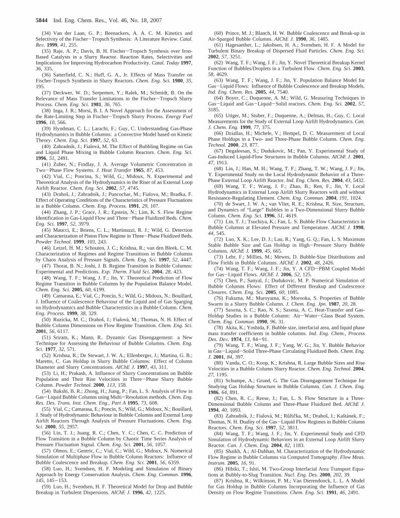
(34) Van der Laan, G. P.; Beenackers, A. A. C. M. Kinetics andSelectivity of the Fischer-Tropsch Synthesis: A Literature Review.Catal.ReV. 1999, 41, 255.
(35) Raje, A. P.; Davis, B. H. Fischer-Tropsch Synthesis over Iron-Based Catalysts in a Slurry Reactor. Reaction Rates, Selectivities andImplications for Improving Hydrocarbon Productivity.Catal. Today1997,36, 335.
(36) Satterfield, C. N.; Huff, G. A., Jr. Effects of Mass Transfer onFischer-Tropsch Synthesis in Slurry Reactors.Chem. Eng. Sci.1980, 35,195.
(37) Deckwer, W. D.; Serpemen, Y.; Ralek, M.; Schmidt, B. On theRelevance of Mass Transfer Limitations in the Fischer-Tropsch SlurryProcess.Chem. Eng. Sci.1981, 36, 765.
(38) Inga, J. R.; Morsi, B. I. A Novel Approach for the Assessment ofthe Rate-Limiting Step in Fischer-Tropsch Slurry Process.Energy Fuel1996, 10, 566.
(39) Hyndman, C. L.; Larachi, F.; Guy, C. Understanding Gas-PhaseHydrodynamics in Bubble Columns: a Convective Model based on KineticTheory.Chem. Eng. Sci.1997, 52, 63.
(40) Zahradnı´k, J.; Fialova, M. The Effect of Bubbling Regime on Gasand Liquid Phase Mixing in Bubble Column Reactors.Chem. Eng. Sci.1996, 51, 2491.
(41) Zuber, N.; Findlay, J. A. Average Volumetric Concentration inTwo-Phase Flow Systems.J. Heat Transfer1965, 87, 453.
(42) Vial, C.; Poncina, S.; Wild, G.; Midoux, N. Experimental andTheoretical Analysis of the Hydrodynamics in the Riser of an External LoopAirlift Reactor. Chem. Eng. Sci.2002, 57, 4745.
(43) Drahosˇ, J.; Zahradnı´k, J.; Puncochar, M.; Fialova, M.; Bradka, F.Effect of Operating Conditions of the Characteristics of Pressure Fluctuationsin a Bubble Column.Chem. Eng. Process.1991, 29, 107.
(44) Zhang, J. P.; Grace, J. R.; Epstein, N.; Lim, K. S. Flow RegimeIdentification in Gas-Liquid Flow and Three-Phase Fluidized Beds.Chem.Eng. Sci.1997, 52, 3979.
(45) Maucci, E.; Briens, C. L.; Martinuzzi, R. J.; Wild, G. Detectionand Characterization of Piston Flow Regime in Three-Phase Fluidized Beds.Powder Technol.1999, 103, 243.
(46) Letzel, H. M.; Schouten, J. C.; Krishna, R.; van den Bleek, C. M.Characterization of Regimes and Regime Transitions in Bubble Columnsby Chaos Analysis of Pressure Signals.Chem. Eng. Sci.1997, 52, 4447.
(47) Thorat, B. N.; Joshi, J. B. Regime Transition in Bubble Columns:Experimental and Predictions.Exp. Therm. Fluid Sci.2004, 28, 423.
(48) Wang, T. F.; Wang, J. F.; Jin, Y. Theoretical Prediction of FlowRegime Transition in Bubble Columns by the Population Balance Model.Chem. Eng. Sci.2005, 60, 6199.
(49) Camarasa, E.; Vial, C.; Poncin, S.; Wild, G.; Midoux, N.; Bouillard,J. Influence of Coalescence Behaviour of the Liquid and of Gas Spargingon Hydrodynamics and Bubble Characteristics in a Bubble Column.Chem.Eng. Process. 1999, 38, 329.
(50) Ruzicka, M. C.; Drahosˇ, J.; Fialova, M.; Thomas, N. H. Effect ofBubble Column Dimensions on Flow Regime Transition.Chem. Eng. Sci.2001, 56, 6117.
(51) Sriram, K.; Mann, R.. Dynamic Gas Disengagement: a NewTechnique for Assessing the Behaviour of Bubble Columns.Chem. Eng.Sci.1977, 32, 571.
(52) Krishna, R.; De Stewart, J. W. A.; Ellenberger, J.; Martina, G. B.;Maretto, C. Gas Holdup in Slurry Bubble Columns: Effect of ColumnDiameter and Slurry Concentrations.AIChE J.1997, 43, 311.
(53) Li, H.; Prakash, A. Influence of Slurry Concentrations on BubblePopulation and Their Rise Velocities in Three-Phase Slurry BubbleColumn.Powder Technol.2000, 113, 158.
(54) Bakshi, B. R.; Zhong, H.; Jiang, P.; Fan, L. S. Analysis of Flow inGas-Liquid Bubble Columns using Multi-Resolution methods.Chem. Eng.Res. Des. Trans. Inst. Chem. Eng., Part A1995, 73, 608.
(55) Vial, C.; Camarasa, E.; Poncin, S.; Wild, G.; Midoux, N.; Bouillard,J. Study of Hydrodynamic Behaviour in Bubble Columns and External LoopAirlift Reactors Through Analysis of Pressure Fluctuations.Chem. Eng.Sci.2000, 55, 2957.
(56) Lin, T. J.; Juang, R. C.; Chen, Y. C.; Chen, C. C. Prediction ofFlow Transition in a Bubble Column by Chaotic Time Series Analysis ofPressure Fluctuation Signal.Chem. Eng. Sci.2001, 56, 1057.
(57) Olmos, E.; Gentric, C.; Vial, C.; Wild, G.; Midoux, N. NumericalSimulation of Multiphase Flow in Bubble Column Reactors: Influence ofBubble Coalescence and Breakup.Chem. Eng. Sci.2001, 56, 6359.
(58) Luo, H.; Svendsen, H. F. Modeling and Simulation of BinaryApproach by Energy Conservation Analysis.Chem. Eng. Commun.1996,145, 145-153.
(59) Luo, H.; Svendsen, H. F. Theoretical Model for Drop and BubbleBreakup in Turbulent Dispersions.AIChE J.1996, 42, 1225.
(60) Prince, M. J.; Blanch, H. W. Bubble Coalescence and Break-up inAir-Sparged Bubble Columns.AIChE J.1990, 36, 1485.
(61) Hagesaether, L.; Jakobsen, H. A.; Svendsen, H. F. A Model forTurbulent Binary Breakup of Dispersed Fluid Particles.Chem. Eng. Sci.2002, 57, 3251.
(62) Wang, T. F.; Wang, J. F.; Jin, Y. Novel Theoretical Breakup KernelFunction of Bubbles/Droplets in a Turbulent Flow.Chem. Eng. Sci.2003,58, 4629.
(63) Wang, T. F.; Wang, J. F.; Jin, Y. Population Balance Model forGas-Liquid Flows: Influence of Bubble Coalescence and Breakup Models.Ind. Eng. Chem. Res.2005, 44, 7540.
(64) Boyer, C.; Duquenne, A. M.; Wild, G. Measuring Techniques inGas-Liquid and Gas-Liquid-Solid reactors.Chem. Eng. Sci.2002, 57,3185.
(65) Utiger, M.; Stuber, F.; Duquenne, A.; Delmas, H.; Guy, C. LocalMeasurements for the Study of External Loop Airlift Hydrodynamics.Can.J. Chem. Eng.1999, 77, 375.
(66) Dziallas, H.; Michele, V.; Hempel, D. C. Measurement of LocalPhase Holdups in a Two- and Three-Phase Bubble Column.Chem. Eng.Technol.2000, 23, 877.
(67) Degaleesan, S.; Dudukovic, M.; Pan, Y. Experimental Study ofGas-Induced Liquid-Flow Structures in Bubble Columns.AIChE J.2001,47, 1913.
(68) Lin, J.; Han, M. H.; Wang, T. F.; Zhang, T. W.; Wang, J. F.; Jin,Y. Experimental Study on the Local Hydrodynamic Behavior of a Three-Phase External Loop Airlift Reactor.Ind. Eng. Chem. Res.2004, 43, 5432.
(69) Wang, T. F.; Wang, J. F.; Zhao, B.; Ren, F.; Jin, Y. LocalHydrodynamics in External Loop Airlift Slurry Reactors with and withoutResistance-Regulating Element.Chem. Eng. Commun.2004, 191, 1024.
(70) de Swart, J. W. A.; van Vliet, R. E.; Krishna, R. Size, Structure,and Dynamics of “Large” Bubbles in a Two-Dimensional Slurry BubbleColumn.Chem. Eng. Sci.1996, 51, 4619.
(71) Lin, T. J.; Tsuchiya, K.; Fan, L. S. Bubble Flow Characteristics inBubble Columns at Elevated Pressure and Temperature.AIChE J.1998,44, 545.
(72) Luo, X. K.; Lee, D. J.; Lau, R.; Yang, G. Q.; Fan, L. S. MaximumStable Bubble Size and Gas Holdup in High-Pressure Slurry BubbleColumns.AIChE J.1999, 45, 665.
(73) Lehr, F.; Millies, M.; Mewes, D. Bubble-Size Distributions andFlow Fields in Bubble Columns.AIChE J.2002, 48, 2426.
(74) Wang, T. F.; Wang, J. F.; Jin, Y. A CFD-PBM Coupled Modelfor Gas-Liquid Flows.AIChE J.2006, 52, 125.
(75) Chen, P.; Sanyal, J.; Dudukovic, M. P. Numerical Simulation ofBubble Columns Flows: Effect of Different Breakup and CoalescenceClosures.Chem. Eng. Sci.2005, 60, 1085.
(76) Fukuma, M.; Muroyama, K.; Morooka, S. Properties of BubbleSwarm in a Slurry Bubble Column.J. Chem. Eng. Jpn.1987, 20, 28.
(77) Saxena, S. C.; Rao, N. S.; Saxena, A. C. Heat-Transfer and Gas-Holdup Studies in a Bubble Column: Air-Water-Glass Bead System.Chem. Eng. Commun.1990, 96, 31.
(78) Akita, K.; Yoshida, F. Bubble size, interfacial area, and liquid phasemass transfer coefficients in bubble columns.Ind. Eng. Chem., ProcessDes. DeV. 1974, 13, 84-91.
(79) Wang, T. F.; Wang, J. F.; Yang, W. G.; Jin, Y. Bubble Behaviorin Gas-Liquid-Solid Three-Phase Circulating Fluidized Beds.Chem. Eng.J. 2001, 84, 397.
(80) Vandu, C. O.; Koop, K.; Krishna, R. Large Bubble Sizes and RiseVelocities in a Bubble Column Slurry Reactor.Chem. Eng. Technol.2004,27, 1195.
(81) Schumpe, A.; Grund, G. The Gas Disengagement Technique forStudying Gas Holdup Structure in Bubble Columns.Can. J. Chem. Eng.1986, 64, 891.
(82) Chen, R. C.; Reese, J.; Fan, L. S. Flow Structure in a Three-Dimensional Bubble Column and Three-Phase Fluidized Bed.AIChE J.1994, 40, 1093.
(83) Zahradnı´k, J.; Fialova, M.; Ruzicka, M.; Drahosˇ, J.; Kastanek, F.;Thomas, N. H. Duality of the Gas-Liquid Flow Regimes in Bubble ColumnReactors.Chem. Eng. Sci.1997, 52, 3811.
(84) Wang, T. F.; Wang, J. F.; Jin, Y. Experimental Study and CFDSimulation of Hydrodynamic Behaviors in an External Loop Airlift SlurryReactor.Can. J. Chem. Eng.2004, 82, 1183.
(85) Shaikh, A.; Al-Dahhan, M. Characterization of the HydrodynamicFlow Regime in Bubble Columns via Computed Tomography.Flow Meas.Instrum.2005, 16, 91.
(86) Hibiki, T.; Ishii, M. Two-Group Interfacial Area Transport Equa-tions at Bubbly-to-Slug Transition.Nucl. Eng. Des.2000, 202, 39.
(87) Krishna, R.; Wilkinson, P. M.; Van Dierendonck, L. L. A Modelfor Gas Holdup in Bubble Columns Incorporating the Influence of GasDensity on Flow Regime Transitions.Chem. Eng. Sci.1991, 46, 2491.
5844 Ind. Eng. Chem. Res., Vol. 46, No. 18, 2007
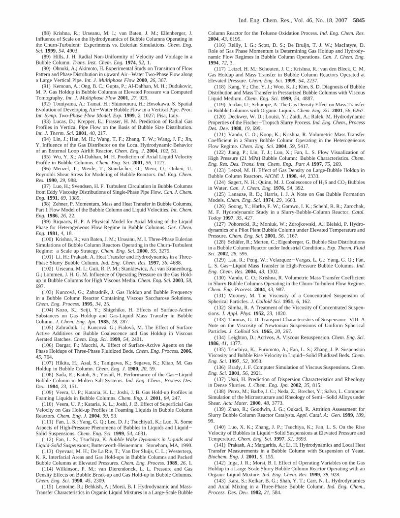
(88) Krishna, R.; Urseanu, M. I.; van Baten, J. M.; Ellenberger, J.Influence of Scale on the Hydrodynamics of Bubble Columns Operating inthe Churn-Turbulent: Experiments vs. Eulerian Simulations.Chem. Eng.Sci.1999, 54, 4903.
(89) Hills, J. H. Radial Non-Uniformity of Velocity and Voidage in aBubble Column.Trans. Inst. Chem. Eng.1974, 52, 1.
(90) Ohnuki, A.; Akimoto, H. Experimental Study on Transition of FlowPattern and Phase Distribution in upward Air-Water Two-Phase Flow alonga Large Vertical Pipe.Int. J. Multiphase Flow2000, 26, 367.
(91) Kemoun, A.; Ong, B. C.; Gupta, P.; Al-Dahhan, M. H.; Dudukovic,M. P. Gas Holdup in Bubble Columns at Elevated Pressure via ComputedTomography.Int. J. Multiphase Flow2001, 27, 929.
(92) Tomiyama, A.; Tamai, H.; Shimomura, H.; Hosokawa, S. SpatialEvolution of Developing Air-Water Bubble Flow in a Vertical Pipe.Proc.Int. Symp. Two-Phase Flow Model. Exp.1999, 2, 1027; Pisa, Italy.
(93) Lucas, D.; Krepper, E.; Prasser, H. M. Prediction of Radial GasProfiles in Vertical Pipe Flow on the Basis of Bubble Size Distribution.Int. J. Therm. Sci.2001, 40, 217.
(94) Lin, J.; Han, M. H.; Wang, T. F.; Zhang, T. W.; Wang, J. F.; Jin,Y. Influence of the Gas Distributor on the Local Hydrodynamic Behaviorof an External Loop Airlift Reactor.Chem. Eng. J.2004, 102, 51.
(95) Wu, Y. X.; Al-Dahhan, M. H. Prediction of Axial Liquid VelocityProfile in Bubble Columns.Chem. Eng. Sci.2001, 56, 1127.
(96) Menzel, T.; Weide, T.; Staudacher, O.; Wein, O.; Onken, U.Reynolds Shear Stress for Modeling of Bubble Reactors.Ind. Eng. Chem.Res.1990, 29, 988.
(97) Luo, H.; Svendsen, H. F. Turbulent Circulation in Bubble Columnsfrom Eddy Viscosity Distributions of Single-Phase Pipe Flow.Can. J. Chem.Eng.1991, 69, 1389.
(98) Zehner, P. Momentum, Mass and Heat Transfer in Bubble Columns,Part 1 Flow Model of the Bubble Column and Liquid Velocities.Int. Chem.Eng.1986, 26, 22.
(99) Riquarts, H. P. A Physical Model for Axial Mixing of the LiquidPhase for Heterogeneous Flow Regime in Bubble Columns.Ger. Chem.Eng.1981, 4, 18.
(100) Krishna, R.; van Baten, J. M.; Urseanu, M. I. Three-Phase EulerianSimulations of Bubble Column Reactors Operating in the Churn-TurbulentRegime: a Scale up Strategy.Chem. Eng. Sci.2000, 55, 3275.
(101) Li, H.; Prakash, A. Heat Transfer and Hydrodynamics in a Three-Phase Slurry Bubble Column.Ind. Eng. Chem. Res.1997, 36, 4688.
(102) Urseanu, M. I.; Guit, R. P. M.; Stankiewicz, A.; van Kranenburg,G.; Lommen, J. H. G. M. Influence of Operating Pressure on the Gas Hold-up in Bubble Columns for High Viscous Media.Chem. Eng. Sci.2003, 58,697.
(103) Kuncova´, G.; Zahradnı´k, J. Gas Holdup and Bubble Frequencyin a Bubble Column Reactor Containing Viscous Saccharose Solutions.Chem. Eng. Process.1995, 34, 25.
(104) Kozo, K.; Seiji, Y.; Shigehiko, H. Effects of Surface-ActiveSubstances on Gas Holdup and Gas-Liquid Mass Transfer in BubbleColumn.J. Chem. Eng. Jpn. 1985, 18, 287.
(105) Zahradnı´k, J.; Kuncova´, G.; Fialova, M. The Effect of SurfaceActive Additives on Bubble Coalescence and Gas Holdup in ViscousAerated Batches.Chem. Eng. Sci.1999, 54, 2401.
(106) Dargar, P.; Macchi, A. Effect of Surface-Active Agents on thePhase Holdups of Three-Phase Fluidized Beds.Chem. Eng. Process.2006,45, 764.
(107) Hikita, H.; Asal, S.; Tanigawa, K.; Segawa, K.; Kitao, M. GasHoldup in Bubble Column.Chem. Eng. J.1980, 20, 59.
(108) Sada, E.; Katoh, S.; Yoshil, H. Performance of the Gas-LiquidBubble Column in Molten Salt Systems.Ind. Eng. Chem., Process Des.DeV. 1984, 23, 151.
(109) Veera, U. P.; Kataria, K. L.; Joshi, J. B. Gas Hold-up Profiles inFoaming Liquids in Bubble Columns.Chem. Eng. J.2001, 84, 247.
(110) Veera, U. P.; Kataria, K. L.; Joshi, J. B. Effect of Superficial GasVelocity on Gas Hold-up Profiles in Foaming Liquids in Bubble ColumnReactors.Chem. Eng. J.2004, 99, 53.
(111) Fan, L. S.; Yang, G. Q.; Lee, D. J.; Tsuchiya1, K.; Luo, X. SomeAspects of High-Pressure Phenomena of Bubbles in Liquids and Liquid-Solid Suspensions.Chem. Eng. Sci.1999, 54, 4681.
(112) Fan, L. S.; Tsuchiya, K.Bubble Wake Dynamics in Liquids andLiquid-Solid Suspensions; Butterworth-Heinemann: Stoneham, MA, 1990.
(113) Oyevaar, M. H.; De La Rie, T.; Van Der Sluijs, C. L.; Westerterp,K. R. Interfacial Areas and Gas Hold-ups in Bubble Columns and PackedBubble Columns at Elevated Pressures.Chem. Eng. Process.1989, 26, 1.
(114) Wilkinson, P. M.; van Dierendonck, L. L. Pressure and GasDensity Effects on Bubble Break-up and Gas Hold-up in Bubble Columns.Chem. Eng. Sci.1990, 45, 2309.
(115) Lemoine, R.; Behkish, A.; Morsi, B. I. Hydrodynamic and Mass-Transfer Characteristics in Organic Liquid Mixtures in a Large-Scale Bubble
Column Reactor for the Toluene Oxidation Process.Ind. Eng. Chem. Res.2004, 43, 6195.
(116) Reilly, I. G.; Scott, D. S.; De Bruijn, T. J. W.; MacIntyre, D.Role of Gas Phase Momentum is Determining Gas Holdup and Hydrody-namic Flow Regimes in Bubble Column Operations.Can. J. Chem. Eng.1994, 72, 3.
(117) Letzel, H. M.; Schouten, J. C.; Krishna, R.; van den Bleek, C. M.Gas Holdup and Mass Transfer in Bubble Column Reactors Operated atElevated Pressure.Chem. Eng. Sci.1999, 54, 2237.
(118) Kang, Y.; Cho, Y. J.; Woo, K. J.; Kim, S. D. Diagnosis of BubbleDistribution and Mass Transfer in Pressurized Bubble Columns with ViscousLiquid Medium.Chem. Eng. Sci.1999, 54, 4887.
(119) Jordan, U.; Schumpe, A. The Gas Density Effect on Mass Transferin Bubble Columns with Organic Liquids.Chem. Eng. Sci.2001, 56, 6267.
(120) Deckwer, W. D.; Louisi, Y.; Zaidi, A.; Ralek, M. HydrodynamicProperties of the Fischer-Tropsch Slurry Process.Ind. Eng. Chem., ProcessDes. DeV. 1980, 19, 699.
(121) Vandu, C. O.; Koop, K.; Krishna, R. Volumetric Mass TransferCoefficient in a Slurry Bubble Column Operating in the HeterogeneousFlow Regime.Chem. Eng. Sci.2004, 59, 5417.
(122) Jiang, P.; Lin, T. J.; Luo, X.; Fan, L. S. Flow Visualization ofHigh Pressure (21 MPa) Bubble Column: Bubble Characteristics.Chem.Eng. Res. Des. Trans. Inst. Chem. Eng., Part A1997, 75, 269.
(123) Letzel, M. H. Effect of Gas Density on Large-Bubble Holdup inBubble Column Reactors.AIChE J.1998, 44, 2333.
(124) Sagert, N. H.; Quinn, M. J. Coalescence of H2S and CO2 Bubblesin Water.Can. J. Chem. Eng.1976, 54, 392.
(125) Lanauze, R. D.; Harris, I. J. A Note on Gas Bubble FormationModels.Chem. Eng. Sci.1974, 29, 1663.
(126) Soong, Y.; Harke, F. W.; Gamwo, I. K.; Schehl, R. R.; Zarochak,M. F. Hydrodynamic Study in a Slurry-Bubble-Column Reactor.Catal.Today1997, 35, 427.
(127) Pohorecki, R.; Moniuk, W.; Zdrojkowski, A.; Bielski, P. Hydro-dynamics of a Pilot Plant Bubble Column under Elevated Temperature andPressure.Chem. Eng. Sci.2001, 56, 1167.
(128) Scha¨fer, R.; Merten, C.; Eigenberger, G. Bubble Size Distributionsin a Bubble Column Reactor under Industrial Conditions.Exp. Therm. FluidSci.2002, 26, 595.
(129) Lau, R.; Peng, W.; Velazquez-Vargas, L. G.; Yang, G. Q.; Fan,L. S. Gas-Liquid Mass Transfer in High-Pressure Bubble Columns.Ind.Eng. Chem. Res.2004, 43, 1302.
(130) Vandu, C. O.; Krishna, R. Volumetric Mass Transfer Coefficientin Slurry Bubble Columns Operating in the Churn-Turbulent Flow Regime.Chem. Eng. Process.2004, 43, 987.
(131) Mooney, M. The Viscosity of a Concentrated Suspension ofSpherical Particles.J. Colloid Sci.1951, 6, 162.
(132) Simha, R. A Treatment of the Viscosity of Concentrated Suspen-sions.J. Appl. Phys.1952, 23, 1020.
(133) Thomas, G. D. Transport Characteristics of Suspension: VIII. ANote on the Viscosity of Newtonian Suspensions of Uniform SphericalParticles.J. Colloid Sci.1965, 20, 267.
(134) Leighton, D.; Acrivos, A. Viscous Resuspension.Chem. Eng. Sci.1986, 41, 1377.
(135) Tsuchiya, K.; Furumoto, A.; Fan, L. S.; Zhang, J. P. SuspensionViscosity and Bubble Rise Velocity in Liquid-Solid Fluidized Beds.Chem.Eng. Sci.1997, 52, 3053.
(136) Brady, J. F. Computer Simulation of Viscous Suspensions.Chem.Eng. Sci.2001, 56, 2921.
(137) Usui, H. Prediction of Dispersion Characteristics and Rheologyin Dense Slurries.J. Chem. Eng. Jpn.2002, 35, 815.
(138) Perez, M.; Barbe, J. C.; Neda, Z.; Brechet, Y.; Salvo, L. ComputerSimulation of the Microstructure and Rheology of Semi-Solid Alloys underShear.Acta Mater.2000, 48, 3773.
(139) Zhao, R.; Goodwin, J. G.; Oukaci, R. Attrition Assessment forSlurry Bubble Column Reactor Catalysts.Appl. Catal. A: Gen.1999, 189,99.
(140) Luo, X. K.; Zhang, J. P.; Tsuchiya, K.; Fan, L. S. On the RiseVelocity of Bubbles in Liquid-Solid Suspensions at Elevated Pressure andTemperature.Chem. Eng. Sci.1997, 52, 3693.
(141) Prakash, A.; Margaritis, A.; Li, H. Hydrodynamics and Local HeatTransfer Measurements in a Bubble Column with Suspension of Yeast.Biochem. Eng. J.2001, 9, 155.
(142) Inga, J. R.; Morsi, B. I. Effect of Operating Variables on the GasHoldup in a Large-Scale Slurry Bubble Column Reactor Operating with anOrganic Liquid Mixture.Ind. Eng. Chem. Res.1999, 38, 928.
(143) Kara, S.; Kelkar, B. G.; Shah, Y. T.; Carr, N. L. Hydrodynamicsand Axial Mixing in a Three-Phase Bubble Column.Ind. Eng. Chem.,Process. Des. DeV. 1982, 21, 584.
Ind. Eng. Chem. Res., Vol. 46, No. 18, 20075845
(144) Kato, Y.; Nishiwaki, A.; Kago, T.; Fukuda, T.; Tanaka, S. GasHoldup and Overall Volumetric Absorption Coefficient in Bubble Columnswith Suspended Solid Particles.Int. Chem. Eng.1973, 13, 562.
(145) Boer, A.; Schrauwen, F. J. M. Gas Distributor for a Reactor. PatentWO 2005/084790, 2005.
(146) Coppens, M. O. Method for Operating a Chemical and/or PhysicalProcess by Means of a Hierarchical Fluid Injection System. Patent WO00/66257, 2000.
(147) Bouaifi, M.; Hebrard, G.; Bastoul, D.; Roustan, M. A ComparativeStudy of Gas Holdup, Bubble Size, Interfacial Area and Mass TransferCoefficients in Stirred Gas-Liquid Reactors and Bubble Columns.Chem.Eng. Process.2001, 40, 97.
(148) Espinoza, R. L.; Steynberg, A. P.; Harding, S.; Labuschagne, J.Hydrogenation of Hydrocarbons. Patent WO 98/37168, 1998.
(149) Shah, Y. T.; Kelkar, B. G.; Godbole, S. P. Design ParametersEstimations for Bubble Column Reactors.AIChE J.1982, 28, 353.
(150) Wilkinson, P. M.; Spek, A. P.; van Dierendonck, L. L. DesignParameters Estimation for Scale-up of High-Pressure Bubble Columns.AIChE J.1992, 38, 544.
(151) Yamashita, F. Effect of Liquid Depth, Column Inclination andBaffle Plates on Gas Holdup in Bubble Columns.J. Chem. Eng. Jpn.1985,18, 349.
(152) Kumar, S. B.; Moslemian, D.; Dudukovic, M. P. Gas-HoldupMeasurements in Bubble Columns Using Computed Tomography.AIChEJ. 1997, 43, 1414.
(153) Thorat, B. N.; Shevade, A. V.; Bhilegaonkar, K. N.; Aglawe, R.H.; Veera, U. P.; Thakre, S. S.; Pandit, A. B.; Sawant, S. B.; Joshi, J. B.Effect of Sparger Design and Height to Diameter Ratio on Fractional GasHold-up in Bubble Columns.Chem. Eng. Res. Des. Trans. Inst. Chem. Eng.,Part A 1998, 76, 823.
(154) Veera, U. P.; Joshi, J. B. Measurement of Gas Hold-up Profilesby Gamma Ray Tomography: Effect of Sparger Design and Height ofDispersion in Bubble Column.Chem. Eng. Res. Des. Trans. Inst. Chem.Eng., Part A1999, 77, 303.
(155) Deckwer, W. D.; Schumpe, A. Improved Tools for Bubble ColumnReactor Design and Scale-up.Chem. Eng. Sci.1993, 48, 889.
(156) Maruyama, T.; Yoshida, S.; Mizushina, T. Flow Transition in aBubble Column.J. Chem. Eng. Jpn.1981, 14, 352.
(157) Sarrafi, A.; Jamialahmadi, M.; Muller-Steinhagen, H.; Smith, J.M. Gas Holdup in Homogeneous and Heterogeneous Gas-Liquid BubbleColumn Reactors.Can. J. Chem. Eng.1999, 77, 11.
(158) Zhu, J. W.; Trivedi, V. H.; Saxena, S. C. Gas-Phase Holdup in aSlurry-Bubble Column. Chem. Eng. Commun.1997, 157, 53.
(159) Yamashita, F. Gas Holdup in Bubble Column with Draft Tubefor Gas Dispersion into Annulus.J. Chem. Eng. Jpn.1998, 31, 289.
(160) Forret, A.; Schweitzer, J. M.; Gauthier, T.; Krishna, R.; Schweich,D. Influence of Scale on the Hydrodynamics of Bubble Column Reactors:an Experimental Study in Columns of 0.1, 0.4 and 1 m Diameters.Chem.Eng. Sci.2003, 58, 719.
(161) Wijffels, R. H.; Verheul, M.; Beverloo, W. A.; Tramper, J. Liquid/Solid Mass Transfer in an Air-Lift Loop Reactor with a Dispersed SolidPhase.J. Chem. Technol. Biotechnol.1998, 71, 147.
(162) Maalej, S.; Benaddam, B.; Otterbein, M. Interfacial Area andVolumetric Mass Transfer Coefficient in a Bubble Reactor at ElevatedPressures.Chem. Eng. Sci.2003, 58, 2365.
(163) Elgozali, A.; Linek, V.; Fialova, M.; Wein, O.; Zahradnik, J.Influence of Viscosity and Surface Tension on Performance of Gas-LiquidContactors with Ejector Type Gas Distributor.Chem. Eng. Sci.2002, 57,2987.
(164) Chaumat, H.; Billet-Duquenne, A. M.; Augier, F.; Mathieu, C.;Delmas, H. Mass Transfer in Bubble Column for Industrial Conditions-Effects of Organic Medium, Gas and Liquid Flow Rates and Column Design.Chem. Eng. Sci.2005, 60, 5930.
(165) Yang, W. G.; Wang, J. F.; Zhou, L. M.; Jin, Y. Gas-Liquid MassTransfer Behavior in Three-Phase CFB Reactors.Chem. Eng. Sci.1999,54, 5523.
(166) Yang, W. G.; Wang, J. F.; Wang, T. F.; Jin, Y. ExperimentalStudy on Gas-Liquid Interfacial Area and Mass Transfer Coefficient inThree-Phase Circulating Fluidized Beds.Chem. Eng. J.2001, 84, 485.
(167) Tang, W. T.; Fan, L. S. Hydrodynamics of a Three-Phase FluidizedBed Containing Low-Density Particles.AIChE J.1989, 35, 355.
(168) Wilkinson, P. M.; Haringa, H.; van Dierendonck, L. L. MassTransfer and Bubble Size in a Bubble Column under Pressure.Chem. Eng.Sci.1994, 49, 1417.
(169) Kojima, H.; Sawai, J.; Suzuki, H. Effect of Pressure on VolumetricMass Transfer Coefficient and Gas Holdup in Bubble Column.Chem. Eng.Sci.1997, 52, 4111.
(170) Yang, W. G.; Wang, J. F.; Jin, Y. Mass Transfer Characteristicsof Syngas Components in Slurry System at Industrial Conditions.Chem.Eng. Technol.2001, 24, 651.
(171) Jin, H. B.; Liu, D. L.; Yang, S. H.; He, G. X.; Guo, Z. W.; Tong,Z. M. Experimental Study of Oxygen Mass Transfer Coefficient in BubbleColumn with High Temperature and High Pressure.Chem. Eng. Technol.2004, 27, 1267.
(172) Ozturk, S. S.; Schumpe, A.; Deckwer, W. D. Organic Liquids ina Bubble Column: Holdups and Mass Transfer Coefficients.AIChE J.1987,33, 1473.
(173) Dewes, I.; Schumpe, A. Gas Density Effect on Mass Transfer inthe Slurry Bubble Column.Chem. Eng. Sci.1997, 52, 4105.
(174) Koide, K.; Takazawa, A.; Komura, M.; Matsunga, H. Gas Holdupand Volumetric Liquid Phase Mass Transfer Coefficient in Solid-SuspendedBubble Column.J. Chem. Eng. Jpn.1984, 17, 459.
(175) Okada, K.; Nagata, Y.; Akagi, Y. Effect of Packed Bed on MassTransfer in External-Loop Airlift Bubble Column.J. Chem. Eng. Jpn.1996,29, 582.
(176) Bai, F.; Wang, L.; Huang, H.; Xu, J.; Caesar, J.; Ridgway, D.;Gu, T.; Moo-Young, M. Oxygen Mass-Transfer Performance of LowViscosity Gas-Liquid-Solid System in a Split-Cylinder Airlift Bioreactor.Biotechnol. Lett.2001, 23, 1109.
(177) Quicker, G.; Schumpe, A.; Deckwer, W. D. Gas-Liquid InterfacialAreas in a Bubble Column with Suspended Solids.Chem. Eng. Sci.1984,39, 179.
(178) Smith, B. C.; Skidmore, D. R. Mass Transfer Phenomena in anAirlift Reactor. Effect of Solids Loading and Temperature.Biotechnol.Bioeng.1990, 35, 483.
(179) Feitkenhauer, H.; Maleski, R.; Markl, H. Airlift-Reactor Designand Test for Aerobic Environmental Bioprocesses with Extremely HighSolid Contents at High Temperature.Water Sci. Technol.2003, 48, 69.
(180) Muller, F. L.; Davidson, F. On the Effects of Surfactants on MassTransfer to Viscous Liquids in Bubble Columns.Chem. Eng. Res. Des.1995, 73, 291.
(181) Vasconcelos, J. M. T.; Rodrigues, J. M. L.; Orvalho, S. C. P.;Alves, S. S.; Mendes, R. L.; Reis, A. Effect of Contaminants on MassTransfer Coefficients in Bubble Column and Airlift Contactors.Chem. Eng.Sci.2003, 58, 1431.
(182) Vazquez, G.; Cancela, M. A.; Riverol, C.; Alvarez, E.; Navaza,J. M. Application of the Danckwerts Method in a Bubble Column: Effectsof Surfactants on Mass Transfer Coefficient and Interfacial Area.Chem.Eng. J.2000, 78, 13.
(183) Painmanakul, P.; Loubie`rea, K.; Hebrard, G.; Mietton-Peuchot,M.; Roustan, M. Effect of Surfactants on Liquid-Side Mass TransferCoefficients.Chem. Eng. Sci.2005, 60, 6480.
(184) Azher, N. E.; Gourich, B.; Vial, C.; Bellhaj, M. S.; Bouzidi, A.;Barkaoui, M.; Ziyad, M. Influence of Alcohol Addition on Gas Hold-up,Liquid Circulation Velocity and Mass Transfer Coefficient in a Split-Rectangular Airlift Bioreactor.Biochem. Eng. J.2005, 23, 161.
(185) Sardeing, R.; Painmanakul, P.; He´brard, G. Effect of Surfactantson Liquid-Side Mass Transfer Coefficients in Gas-Liquid Systems: A FirstStep to Modeling.Chem. Eng. Sci.2006, 61, 6249.
(186) Stegeman, D.; Knop, P. A.; Wijnands, A. J. G.; Westerterp, K.R. Interfacial Area and Gas Holdup in a Bubble Column Reactor at ElevatedPressures.Ind. Eng. Chem. Res.1996, 35, 3842.
(187) Pohorecki, R.; Moniuk, W.; Zdrojkowski, A. Hydrodynamics ofa Bubble Column under Elevated Pressure.Chem. Eng. Sci.1999, 54, 5187.
(188) Srinivasan, R.; Xu, L.; Spicer, R. L.; Tungate, F. L.; Davis, B. H.Fischer-Tropsch Catalysts. Attrition of Carbided Iron Catalyst in the SlurryPhase.Fuel Sci. Technol. Int.1996, 14, 1337.
(189) Zhou, P. Z.; Srivastava, R. D.Status ReView of Fischer-TropschSlurry Reactor Catalyst/Wax Separation Techniques; Prepared for the U.S.Department of Energy, Pittsburgh Energy Technology Center: Pittsburgh,PA, 1991.
(190) Benham, C. B.; Yakobson, D. L.; Bohn, M. S. Catalyst/WaxSeparation Device for Slurry Fischer-Tropsch Reactor. US Patent 6,068,-760, 2000.
(191) Clerici, G. C. E.; Belmonte, G. Separation/Filtration Device usedin a Process for the Production of Hydrocarbons from Synthesis Gas inSlurry Reactors. GB Patent 2,403,433, 2005.
(192) Rytter, E.; Lian, P.; Myrstad, T.; Roterud, P.T.; Solbakken, A.Method of Conducting Catalytic Converter Multi-Phase Reaction. US Patent5,422,375, 1993.
(193) Jager, B.; Steynberg, A. P.; Inga, J. R.; Kellkens, R. C.; Smith,M. A.; Malherbe, F. E. J. Process for Producing Liquid and, Optionally,Gaseous Products from Gaseous Reactants. US Patent 5,599,849, 1997.
(194) Anderson, J. H. Internal Filter for Fischer-Tropsch Catalyst/WaxSeparation. US Patent 6,652,760, 2003.
5846 Ind. Eng. Chem. Res., Vol. 46, No. 18, 2007
(195) Muller, P. Guaranteeing Process Industries High Product Quality& Yield. Filtr. Sep.2003, 40, 34.
(196) White, C. M.; Quiring, M. S.; Jensen, K. L.; Hickey, R. F.;Gillham, L. D. Separation of Catalyst from Fischer-Tropsch Slurry. USPatent 5,827,903, 1998.
(197) Brioles, J. M.; Wan, Y. D.; Kilpatric, P. K.; Roberts, G. W.Separation of Fischer-Tropsch Wax from Catalyst using Near-Critical FluidExtraction: Analysis of Process Feasibility.Energy Fuel1999, 13, 667.
(198) Brennan, J. A.; Chester, A. W. ; Chu, Y. F.; High GradientMagnetic Separation. US Patent 4,605,678, 1986.
(199) Espinoza, R. L.; Mohedas, S. R.; Odueyungbo, S.; Ortego, J. D.Solid-Liquid Separation System. US Patent 6,833,078, 2004.
(200) Bello, R. A.; Robinson, C. W.; Moo-Young, M. Prediction of theVolumetric Mass Transfer Coefficient in Pneumatic Contactor.Chem. Eng.Sci.1985, 40, 53.
(201) Weiland, P.; Onken, U. Differences in the Behaviour of BubbleColumns and Airlift Loop Reactors.Ger. Chem. Eng.1981, 4, 174.
(202) Kawase, Y.; Hashiguchi, N. Gas-Liquid Mass Transfer inExternal-Loop Airlift Columns with Newtonian and non-Newtonian Fluids.Chem. Eng. J.1996, 62, 35.
(203) Lu, W. J.; Hwang, S. J.; Chang, C. M. Liquid Velocity and GasHoldup in Three-Phase Internal Airlift Reactors with Low-Density Particles.Chem. Eng. Sci.1995, 50, 1301.
(204) Freitas, C.; Fialova´, M.; Zahradnik, J.; Teixeira, J. A. Hydrody-namics of a Three-Phase External-Loop Airlift Bioreactor.Chem. Eng. Sci.2000, 55, 4961.
(205) Hwang, S. J.; Cheng, Y. L. Gas Holdup and Liquid Velocity inThree-Phase Internal-Loop Airlift Reactors.Chem. Eng. Sci.1997, 52, 3949.
(206) Garcı´a-Calvo, E.; Rodrı´guez, A.; Prados, A.; Klein, J. A FluidDynamic Model for Three-Phase Airlift Reactors.Chem. Eng. Sci.1999,54, 2359.
(207) Couvert, A.; Roustan, M.; Chatellier, P. Two-Phase HydrodynamicStudy of a Rectangular Air-Lift Loop Reactor with an Internal Baffle.Chem.Eng. Sci.1999, 54, 5245.
(208) Dreher, A. J.; Krishna, R. Liquid-Phase Backmixing in Bubblecolumns, Structured by Introduction of Partition Plates.Catal. Today2001,69, 165.
(209) Bando, Y.; Fujimori, K.; Terazawa, H.; Yasuda, K.; Nakamura,M. Effects of Equipment Dimensions on Circulation Flow Rates of Liquidand Gas in Bubble Column with Draft Tube.J. Chem. Eng. Jpn.2000, 33,379.
(210) Chisti, Y.; Kasper, M.; Moo-Young, M. Mass Transfer inExternal-Loop Airlift Bioreactors using Static Mixers.Can. J. Chem. Eng.1990, 68, 45.
(211) Lin, C. H.; Fang, B. S.; Wu, C. S.; Fang, H. Y.; Kuo, T. F.; Hu,C. Y. Oxygen Transfer and Mixing in a Tower Cycling Fermentor.Biotechnol. Bioeng.1976, 18, 1557-1572.
(212) Stejskal, J.; Potucek, F. Oxygen Transfer in Liquids.Biotechnol.Bioeng.1985, 27, 503.
(213) Nikakhtari, H.; Hill, G. A. Enhanced Oxygen Mass Transfer inan External Loop Airlift Bioreactor using a Packed Bed.Ind. Eng. Chem.Res.2004, 43, 6195.
(214) Bendjaballah, N.; Dhaouadi, H.; Poncin, S.; Midoux, N.; Hornut,J. M.; Wild, G. Hydrodynamics and Flow Regimes in External Loop AirliftReactors.Chem. Eng. Sci.1999, 54, 5211.
(215) Krichnavaruk, S.; Pavasant, P. Analysis of Gas-Liquid MassTransfer in an Airlift Contactor with Perforated Plate.Chem. Eng. J.2002,89, 203.
(216) Zhang, T. W.; Wang, J. F.; Wang, T. F.; Lin, J.; Jin, Y. Effect ofInternal on the Hydrodynamics in External-Loop Airlift Reactors.Chem.Eng. Process.2005, 44, 81.
(217) Yu, W.; Wang, T. F.; Liu, M. L.; Wang, Z. W. Study on theHydrodynamics in a Multi-Stage Internal-Loop Airlift Slurry Reactor.The9th China-Japan Symposium on Fluidization, Beijing, China, December18-20, 2006; 155.
(218) Xia, Y. K.; Peng, F. F.; Wolfe, E. CFD Simulation of Alleviationof Fluid Back Mixing by Baffles in Bubble Column.Miner. Eng.2006,19, 925.
(219) Alvarea, J.; Al-Dahhanb, M. H. Liquid Phase Mixing in TrayedBubble Column Reactors.Chem. Eng. Sci.2006, 61, 1819.
(220) Oey, R. S.; Mudde, R. F.; Portela, L. M.; van den Akker, H. E.A. Simulation of a Slurry Airlift using a Two-Fluid Model.Chem. Eng.Sci.2001, 56, 673.
(221) Delnoij, E.; Lammers, F. A.; Kuipers, J. A. M.; Van Swaaij, W.P. M. Dynamic Simulation of Dispersed Gas-Liquid Two-Phase Flow usinga Discrete Bubble Model.Chem. Eng. Sci.1997, 52, 1429.
(222) Sokolichin, A.; Eigenberger, G.; Lapin, A.; Lu¨bbert, A. DynamicNumerical Simulation of Gas-Liquid Two-Phase Flows: Euler-Eulerversus Euler-Lagrange.Chem. Eng. Sci.1997, 52, 611.
(223) Drew, D. A. Mathematical Modeling of Two-Phase Flow.Annu.ReV. Fluid Mech.1983, 15, 261.
(224) Lahey, R. T.; Drew, D. A. On the Development of Multidimen-sional Two-Fluid Models for Vapor/Liquid Two-Phase Flows.Chem. Eng.Commun.1992, 118, 125.
(225) Jakobsen, H. A.; Sannes, B. H.; Grevskott, S.; Svendsen, F.Modeling of Vertical Bubble-Driven Flows.Ind. Eng. Chem. Res.1997,36, 4052.
(226) Jakobsen, H. A.; Lindborg, H.; Dorao, C. A. Modeling of BubbleColumn Reactors: Progress and Limitations.Ind. Eng. Chem. Res.2005,44, 5107.
(227) Rafique, M.; Chen, P.; Dudukovic, M. P. Computational Modelingof Gas-Liquid Flow in Bubble Columns.ReV. Chem. Eng.2004, 20, 225.
(228) Jakobsen, H. A. Phase Distribution Phenomena in Two-PhaseBubble Column Reactors.Chem. Eng. Sci.2001, 56, 1049.
(229) Pan, Y.; Dudukovic, M. P.; Chang, M. Dynamic Simulation ofBubbly Flow in Bubble Columns.Chem. Eng. Sci.1999, 54, 2481.
(230) Hua, J.; Wang, C. H. Numerical Simulation of Bubble-DrivenLiquid Flows.Chem. Eng. Sci.2000, 55, 4159.
(231) Pfleger, D.; Becker, S. Modelling and Simulation of the DynamicFlow Behaviour in a Bubble Column.Chem. Eng. Sci.2001, 56, 1737.
(232) Colella, D.; Vinci, D.; Bagatin, R.; Masi, M.; Bakr, E. A. A Studyon Coalescence and Breakage Mechanisms in Three Different BubbleColumns.Chem. Eng. Sci.1999, 54, 4767.
(233) Sha, Z.; Laari, A.; Turunen, I. Implementation of PopulationBalance into Multiphase-Model in CFD Simulation for Bubble Column.CHISA 16th International Congress of Chemical Process Engineering,Prague, Czech Republic, August 22-26, 2004; 445.
(234) Liu, T. J.; Bankoff, S. G. Structure of Air-Water Bubbly Flowin a Vertical Pipe-II. Void Fraction, Bubble Velocity and Bubble SizeDistribution. Int. J. Heat Mass Transfer1993, 36, 1061.
ReceiVed for reView March 3, 2007ReVised manuscript receiVed May 17, 2007
AcceptedJune 13, 2007
IE070330T
Ind. Eng. Chem. Res., Vol. 46, No. 18, 20075847
Recommended