ST4000VX002
ST3000VX004
ST2000VX004
ST1000VX002
100759604, Rev. FSeptember 2015
SV35/Suveillance HDDProduct Manual
© 2015, Seagate Technology LLC All rights reserved.Publication number: 100759604, Rev. F September 2015
Seagate, Seagate Technology and the Spiral logo are registered trademarks of Seagate Technology LLC in the United States and/or other countries. AccuTrac, OptiCache and SeaTools areeither trademarks or registered trademarks of Seagate Technology LLC or one of its affiliated companies in the United States and/or other countries. All other trademarks or registeredtrademarks are the property of their respective owners.No part of this publication may be reproduced in any form without written permission of Seagate Technology LLC.Call 877-PUB-TEK1 (877-782-8351) to request permission.
When referring to drive capacity, one gigabyte, or GB, equals one billion bytes and one terabyte, or TB, equals one trillion bytes. Your computer’s operating system may use a differentstandard of measurement and report a lower capacity. In addition, some of the listed capacity is used for formatting and other functions, and thus will not be available for data storage.Actual quantities will vary based on various factors, including file size, file format, features and application software. Actual data rates may vary depending on operating environment andother factors. The export or re-export of hardware or software containing encryption may be regulated by the U.S. Department of Commerce, Bureau of Industry and Security (for moreinformation, visit www.bis.doc.gov), and controlled for import and use outside of the U.S. Seagate reserves the right to change, without notice, product offerings or specifications.
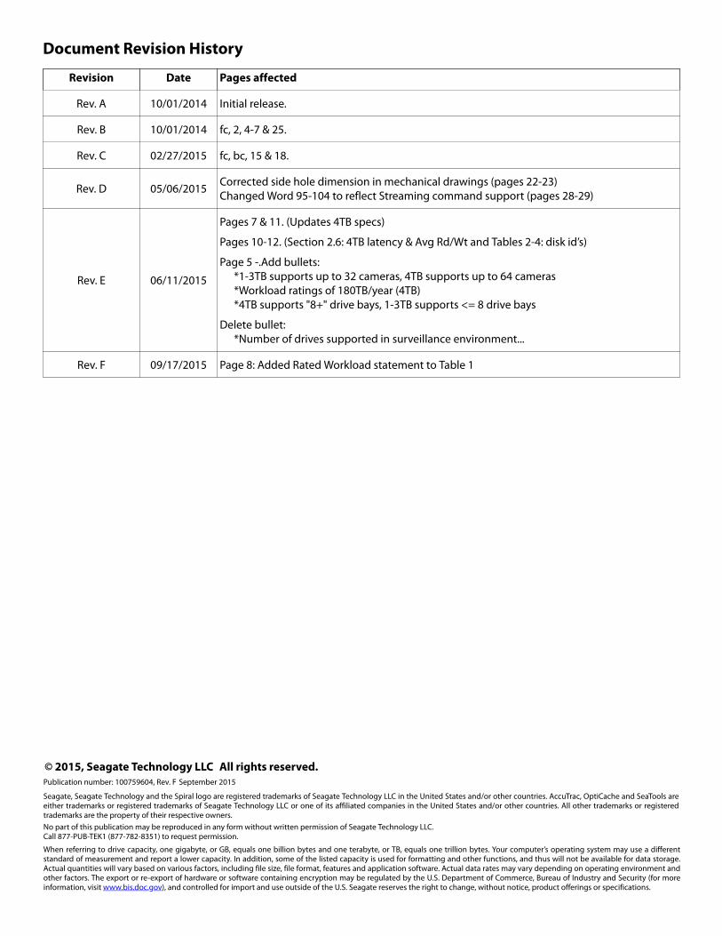
Document Revision History
Revision Date Pages affected
Rev. A 10/01/2014 Initial release.
Rev. B 10/01/2014 fc, 2, 4-7 & 25.
Rev. C 02/27/2015 fc, bc, 15 & 18.
Rev. D 05/06/2015Corrected side hole dimension in mechanical drawings (pages 22-23)Changed Word 95-104 to reflect Streaming command support (pages 28-29)
Rev. E 06/11/2015
Pages 7 & 11. (Updates 4TB specs)
Pages 10-12. (Section 2.6: 4TB latency & Avg Rd/Wt and Tables 2-4: disk id’s)
Page 5 -.Add bullets:*1-3TB supports up to 32 cameras, 4TB supports up to 64 cameras*Workload ratings of 180TB/year (4TB)*4TB supports "8+" drive bays, 1-3TB supports <= 8 drive bays
Delete bullet:*Number of drives supported in surveillance environment...
Rev. F 09/17/2015 Page 8: Added Rated Workload statement to Table 1
Seagate SV35/Suveillance +SRS HDD Product Manual, Rev. F 2
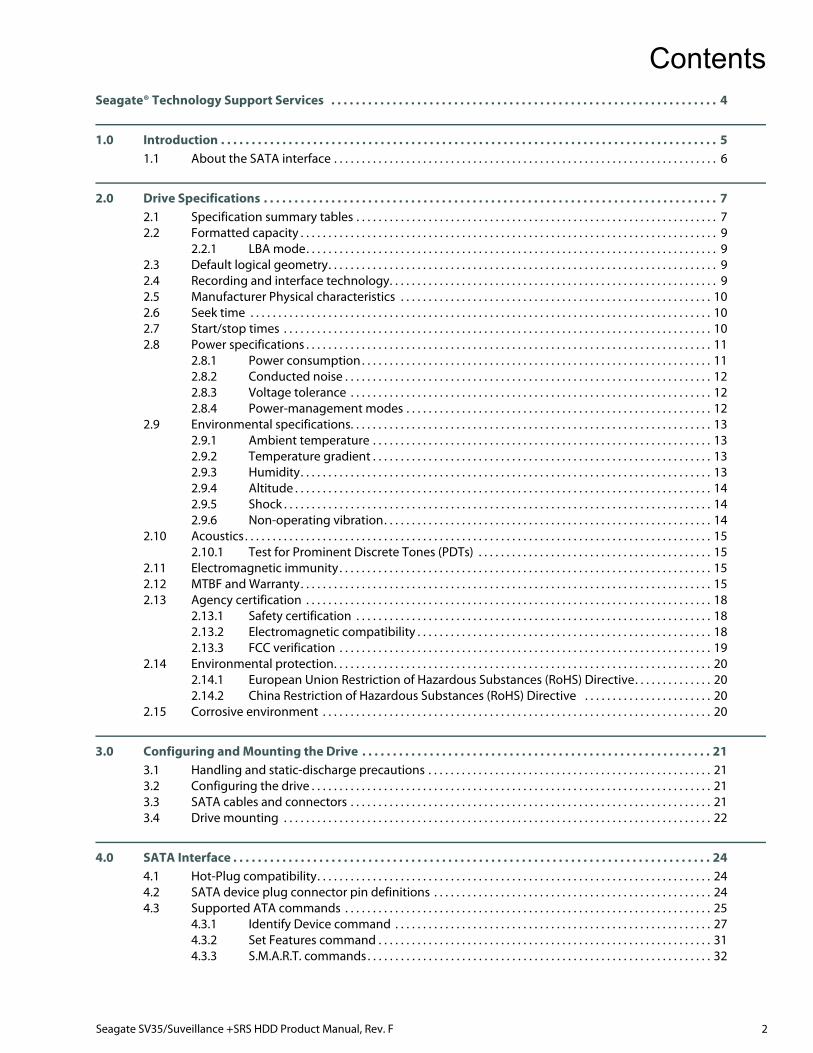
ContentsSeagate® Technology Support Services . . . . . . . . . . . . . . . . . . . . . . . . . . . . . . . . . . . . . . . . . . . . . . . . . . . . . . . . . . . . . . . 4
1.0 Introduction . . . . . . . . . . . . . . . . . . . . . . . . . . . . . . . . . . . . . . . . . . . . . . . . . . . . . . . . . . . . . . . . . . . . . . . . . . . . . . . . . 51.1 About the SATA interface . . . . . . . . . . . . . . . . . . . . . . . . . . . . . . . . . . . . . . . . . . . . . . . . . . . . . . . . . . . . . . . . . . . . . 6
2.0 Drive Specifications . . . . . . . . . . . . . . . . . . . . . . . . . . . . . . . . . . . . . . . . . . . . . . . . . . . . . . . . . . . . . . . . . . . . . . . . . . 72.1 Specification summary tables . . . . . . . . . . . . . . . . . . . . . . . . . . . . . . . . . . . . . . . . . . . . . . . . . . . . . . . . . . . . . . . . . 72.2 Formatted capacity . . . . . . . . . . . . . . . . . . . . . . . . . . . . . . . . . . . . . . . . . . . . . . . . . . . . . . . . . . . . . . . . . . . . . . . . . . . 9
2.2.1 LBA mode. . . . . . . . . . . . . . . . . . . . . . . . . . . . . . . . . . . . . . . . . . . . . . . . . . . . . . . . . . . . . . . . . . . . . . . . . . 92.3 Default logical geometry. . . . . . . . . . . . . . . . . . . . . . . . . . . . . . . . . . . . . . . . . . . . . . . . . . . . . . . . . . . . . . . . . . . . . . 92.4 Recording and interface technology. . . . . . . . . . . . . . . . . . . . . . . . . . . . . . . . . . . . . . . . . . . . . . . . . . . . . . . . . . . 92.5 Manufacturer Physical characteristics . . . . . . . . . . . . . . . . . . . . . . . . . . . . . . . . . . . . . . . . . . . . . . . . . . . . . . . . 102.6 Seek time . . . . . . . . . . . . . . . . . . . . . . . . . . . . . . . . . . . . . . . . . . . . . . . . . . . . . . . . . . . . . . . . . . . . . . . . . . . . . . . . . . . 102.7 Start/stop times . . . . . . . . . . . . . . . . . . . . . . . . . . . . . . . . . . . . . . . . . . . . . . . . . . . . . . . . . . . . . . . . . . . . . . . . . . . . . 102.8 Power specifications . . . . . . . . . . . . . . . . . . . . . . . . . . . . . . . . . . . . . . . . . . . . . . . . . . . . . . . . . . . . . . . . . . . . . . . . . 11
2.8.1 Power consumption . . . . . . . . . . . . . . . . . . . . . . . . . . . . . . . . . . . . . . . . . . . . . . . . . . . . . . . . . . . . . . . 112.8.2 Conducted noise . . . . . . . . . . . . . . . . . . . . . . . . . . . . . . . . . . . . . . . . . . . . . . . . . . . . . . . . . . . . . . . . . . 122.8.3 Voltage tolerance . . . . . . . . . . . . . . . . . . . . . . . . . . . . . . . . . . . . . . . . . . . . . . . . . . . . . . . . . . . . . . . . . 122.8.4 Power-management modes . . . . . . . . . . . . . . . . . . . . . . . . . . . . . . . . . . . . . . . . . . . . . . . . . . . . . . . 12
2.9 Environmental specifications. . . . . . . . . . . . . . . . . . . . . . . . . . . . . . . . . . . . . . . . . . . . . . . . . . . . . . . . . . . . . . . . . 132.9.1 Ambient temperature . . . . . . . . . . . . . . . . . . . . . . . . . . . . . . . . . . . . . . . . . . . . . . . . . . . . . . . . . . . . . 132.9.2 Temperature gradient . . . . . . . . . . . . . . . . . . . . . . . . . . . . . . . . . . . . . . . . . . . . . . . . . . . . . . . . . . . . . 132.9.3 Humidity. . . . . . . . . . . . . . . . . . . . . . . . . . . . . . . . . . . . . . . . . . . . . . . . . . . . . . . . . . . . . . . . . . . . . . . . . . 132.9.4 Altitude . . . . . . . . . . . . . . . . . . . . . . . . . . . . . . . . . . . . . . . . . . . . . . . . . . . . . . . . . . . . . . . . . . . . . . . . . . . 142.9.5 Shock . . . . . . . . . . . . . . . . . . . . . . . . . . . . . . . . . . . . . . . . . . . . . . . . . . . . . . . . . . . . . . . . . . . . . . . . . . . . . 142.9.6 Non-operating vibration. . . . . . . . . . . . . . . . . . . . . . . . . . . . . . . . . . . . . . . . . . . . . . . . . . . . . . . . . . . 14
2.10 Acoustics . . . . . . . . . . . . . . . . . . . . . . . . . . . . . . . . . . . . . . . . . . . . . . . . . . . . . . . . . . . . . . . . . . . . . . . . . . . . . . . . . . . . 152.10.1 Test for Prominent Discrete Tones (PDTs) . . . . . . . . . . . . . . . . . . . . . . . . . . . . . . . . . . . . . . . . . . 15
2.11 Electromagnetic immunity. . . . . . . . . . . . . . . . . . . . . . . . . . . . . . . . . . . . . . . . . . . . . . . . . . . . . . . . . . . . . . . . . . . 152.12 MTBF and Warranty. . . . . . . . . . . . . . . . . . . . . . . . . . . . . . . . . . . . . . . . . . . . . . . . . . . . . . . . . . . . . . . . . . . . . . . . . . 152.13 Agency certification . . . . . . . . . . . . . . . . . . . . . . . . . . . . . . . . . . . . . . . . . . . . . . . . . . . . . . . . . . . . . . . . . . . . . . . . . 18
2.13.1 Safety certification . . . . . . . . . . . . . . . . . . . . . . . . . . . . . . . . . . . . . . . . . . . . . . . . . . . . . . . . . . . . . . . . 182.13.2 Electromagnetic compatibility . . . . . . . . . . . . . . . . . . . . . . . . . . . . . . . . . . . . . . . . . . . . . . . . . . . . . 182.13.3 FCC verification . . . . . . . . . . . . . . . . . . . . . . . . . . . . . . . . . . . . . . . . . . . . . . . . . . . . . . . . . . . . . . . . . . . 19
2.14 Environmental protection. . . . . . . . . . . . . . . . . . . . . . . . . . . . . . . . . . . . . . . . . . . . . . . . . . . . . . . . . . . . . . . . . . . . 202.14.1 European Union Restriction of Hazardous Substances (RoHS) Directive. . . . . . . . . . . . . . 202.14.2 China Restriction of Hazardous Substances (RoHS) Directive . . . . . . . . . . . . . . . . . . . . . . . 20
2.15 Corrosive environment . . . . . . . . . . . . . . . . . . . . . . . . . . . . . . . . . . . . . . . . . . . . . . . . . . . . . . . . . . . . . . . . . . . . . . 20
3.0 Configuring and Mounting the Drive . . . . . . . . . . . . . . . . . . . . . . . . . . . . . . . . . . . . . . . . . . . . . . . . . . . . . . . . . 213.1 Handling and static-discharge precautions . . . . . . . . . . . . . . . . . . . . . . . . . . . . . . . . . . . . . . . . . . . . . . . . . . . 213.2 Configuring the drive . . . . . . . . . . . . . . . . . . . . . . . . . . . . . . . . . . . . . . . . . . . . . . . . . . . . . . . . . . . . . . . . . . . . . . . . 213.3 SATA cables and connectors . . . . . . . . . . . . . . . . . . . . . . . . . . . . . . . . . . . . . . . . . . . . . . . . . . . . . . . . . . . . . . . . . 213.4 Drive mounting . . . . . . . . . . . . . . . . . . . . . . . . . . . . . . . . . . . . . . . . . . . . . . . . . . . . . . . . . . . . . . . . . . . . . . . . . . . . . 22
4.0 SATA Interface . . . . . . . . . . . . . . . . . . . . . . . . . . . . . . . . . . . . . . . . . . . . . . . . . . . . . . . . . . . . . . . . . . . . . . . . . . . . . . 244.1 Hot-Plug compatibility. . . . . . . . . . . . . . . . . . . . . . . . . . . . . . . . . . . . . . . . . . . . . . . . . . . . . . . . . . . . . . . . . . . . . . . 244.2 SATA device plug connector pin definitions . . . . . . . . . . . . . . . . . . . . . . . . . . . . . . . . . . . . . . . . . . . . . . . . . . 244.3 Supported ATA commands . . . . . . . . . . . . . . . . . . . . . . . . . . . . . . . . . . . . . . . . . . . . . . . . . . . . . . . . . . . . . . . . . . 25
4.3.1 Identify Device command . . . . . . . . . . . . . . . . . . . . . . . . . . . . . . . . . . . . . . . . . . . . . . . . . . . . . . . . . 274.3.2 Set Features command . . . . . . . . . . . . . . . . . . . . . . . . . . . . . . . . . . . . . . . . . . . . . . . . . . . . . . . . . . . . 314.3.3 S.M.A.R.T. commands. . . . . . . . . . . . . . . . . . . . . . . . . . . . . . . . . . . . . . . . . . . . . . . . . . . . . . . . . . . . . . 32
Seagate SV35/Suveillance +SRS HDD Product Manual, Rev. F 3
FiguresFigure 1 Attaching SATA cabling. . . . . . . . . . . . . . . . . . . . . . . . . . . . . . . . . . . . . . . . . . . . . . . . . . . . . . . . . . . . . . . . . . . . . . . . 21Figure 2 Mounting dimensions (4 & 3-disk: 4TB, 3TB and 2TB models) . . . . . . . . . . . . . . . . . . . . . . . . . . . . . . . . . . . . 22Figure 3 Mounting dimensions (1-Disk: 1TB model) . . . . . . . . . . . . . . . . . . . . . . . . . . . . . . . . . . . . . . . . . . . . . . . . . . . . . 23
Seagate SV35/Suveillance +SRS HDD Product Manual, Rev. F 4
For information regarding online support and services, visit: http://www.seagate.com/contacts/
Available services include:• Presales & Technical support• Global Support Services telephone numbers & business hours• Authorized Service Centers
For information regarding Warranty Support, visit: http://www.seagate.com/support/warranty-and-replacements/
For information regarding data recovery services, visit: http://www.seagate.com/services-software/seagate-recovery-services/recover/
For Seagate OEM and Distribution partner portal, visit: http://www.seagate.com/partners
For Seagate reseller portal, visit: http://www.seagate.com/partners
Seagate® Technology Support Services
1.0 Introduction
This manual describes the functional, mechanical and interface specifications for the following:Seagate SV35/Suveillance HDD +SRS model drives:
These drives provide the following key features:
• Enterprise-class reliability for 24×7 video surveillance applications
• Thermal monitoring and reporting for 24×7 operations
• Uncompromising reliability supports flexible surveillance design with case temperatures up to 70ºC
• 1-3TB supports up to 32 cameras, 4TB supports up to 64 cameras
• Workload ratings of 180TB/year (4TB)
• 4TB supports "8+" drive bays, 1-3TB supports <= 8 drive bays
• Performance-tuned for seamless video applications
• Built-in error recovery for non-stop video streaming
• Best-in-class acoustic performance means virtually silent operation
• High instantaneous (burst) data-transfer rates (up to 600MB per second).
• TGMR recording technology provides the drives with increased areal density.
• State-of-the-art cache and on-the-fly error-correction algorithms
• Native Command Queuing with command ordering to increase performance in demanding applications
• Full-track multiple-sector transfer capability without local processor intervention
• AcuTrac™ servo technology delivers dependable performance, even with hard drive track widths of only 75 nanometers.
• OptiCache™ technology boosts overall performance by as much as 45% over the previous generation.
• Quiet operation
• Compliant with RoHS requirements in China and Europe
• Diagnostic software performs a drive self-test that eliminates unnecessary drive returns.
• Support for S.M.A.R.T. drive monitoring and reporting
• Supports latching SATA cables and connectors
• Worldwide Name (WWN) capability uniquely identifies the drive.
• <1% AFR- designed for high write duty cycle across Seagate SV35/Suveillance +SRS HDD
• Streaming video optimization - consistent command completion times & ERC support across Seagate SV35/Suveillance +SRS HDD
• ATA AV Command support - streaming video command support across Seagate SV35/Suveillance +SRS HDD
• Transient power on management - <=2A spin-up current across Seagate SV35/Suveillance +SRS HDD
• Rotational Vibration - mitigation of system level rotational vibration inside Seagate SV35/Suveillance +SRS HDD
ST4000VX002(Surveillance)
ST3000VX004(SV35)
ST2000VX004(SV35)
ST1000VX002(SV35)
Seagate SV35/Suveillance +SRS HDD Product Manual, Rev. F 5
Introduction
1.1 About the SATA interfaceThe Serial ATA (SATA) interface provides several advantages over the traditional (parallel) ATA interface. The primaryadvantages include:
• Easy installation and configuration with true plug-and-play connectivity. It is not necessary to set any jumpers or otherconfiguration options.
• Thinner and more flexible cabling for improved enclosure airflow and ease of installation.
• Scalability to higher performance levels.
In addition, SATA makes the transition from parallel ATA easy by providing legacy software support. SATA was designed toallow users to install a SATA host adapter and SATA disk drive in the current system and expect all of the existingapplications to work as normal.
The SATA interface connects each disk drive in a point-to-point configuration with the SATA host adapter. There is nomaster/slave relationship with SATA devices like there is with parallel ATA. If two drives are attached on one SATA hostadapter, the host operating system views the two devices as if they were both “masters” on two separate ports. Thisessentially means both drives behave as if they are Device 0 (master) devices.
The SATA host adapter and drive share the function of emulating parallel ATA device behavior to provide backwardcompatibility with existing host systems and software. The Command and Control Block registers, PIO and DMA datatransfers, resets, and interrupts are all emulated.
The SATA host adapter contains a set of registers that shadow the contents of the traditional device registers, referred to asthe Shadow Register Block. All SATA devices behave like Device 0 devices. For additional information about how SATAemulates parallel ATA, refer to the “Serial ATA International Organization: Serial ATA Revision 3.0.” The specification can bedownloaded from www.sata-io.org.
Note
The host adapter may, optionally, emulate a master/slave environment to host software where two devices on separate SATA ports are represented to host software as a Device 0 (master) and Device 1 (slave) accessed at the same set of host bus addresses. A host adapter that emulates a master/slave environment manages two sets of shadow registers. This is not a typical SATA environment.
Seagate SV35/Suveillance +SRS HDD Product Manual, Rev. F 6
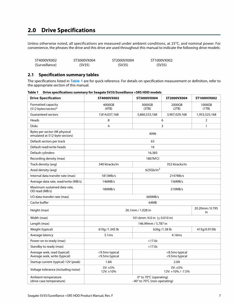
2.0 Drive Specifications
Unless otherwise noted, all specifications are measured under ambient conditions, at 25°C, and nominal power. Forconvenience, the phrases the drive and this drive are used throughout this manual to indicate the following drive models:
2.1 Specification summary tablesThe specifications listed in Table 1 are for quick reference. For details on specification measurement or definition, refer tothe appropriate section of this manual.
ST4000VX002(Surveillance)
ST3000VX004(SV35)
ST2000VX004(SV35)
ST1000VX002(SV35)
Table 1 Drive specifications summary for Seagate SV35/Suveillance +SRS HDD models
Drive Specification ST4000VX002 ST3000VX004 ST2000VX004 ST1000VX002
Formatted capacity (512 bytes/sector)*
4000GB (4TB)
3000GB (3TB)
2000GB(2TB)
1000GB(1TB)
Guaranteed sectors 7,814,037,168 5,860,533,168 3,907,029,168 1,953,525,168
Heads 8 6 2
Disks 4 3 1
Bytes per sector (4K physicalemulated at 512-byte sectors) 4096
Default sectors per track 63
Default read/write heads 16
Default cylinders 16,383
Recording density (max) 1807kFCI
Track density (avg) 340 ktracks/in 352 ktracks/in
Areal density (avg) 625Gb/in2
Internal data transfer rate (max) 1813Mb/s 2147Mb/s
Average data rate, read/write (MB/s) 146MB/s 156MB/s
Maximum sustained data rate,OD read (MB/s) 180MB/s 210MB/s
I/O data-transfer rate (max) 600MB/s
Cache buffer 64MB
Height (max) 26.1mm / 1.028 in 20.20mm / 0.795 in
Width (max) 101.6mm /4.0 in (+ 0.010 in)
Length (max) 146.99mm / 5.787 in
Weight (typical) 610g /1.345 lb 626g /1.38 lb 415g/0.915lb
Average latency 5.1ms 4.16ms
Power-on to ready (max) <17.0s
Standby to ready (max) <17.0s
Average seek, read (typical)Average seek, write (typical)
<9.5ms typical<9.5ms typical
<8.5ms typical<9.5ms typical
Startup current (typical) 12V (peak) 1.8A 2.0A
Voltage tolerance (including noise) 5V: ±5%12V: ±10%
5V: ±5%12V: +10% / -7.5%
Ambient temperature(drive case temperature)
0° to 70°C (operating)–40° to 70°C (non-operating)
Seagate SV35/Suveillance +SRS HDD Product Manual, Rev. F 7
Drive Specifications
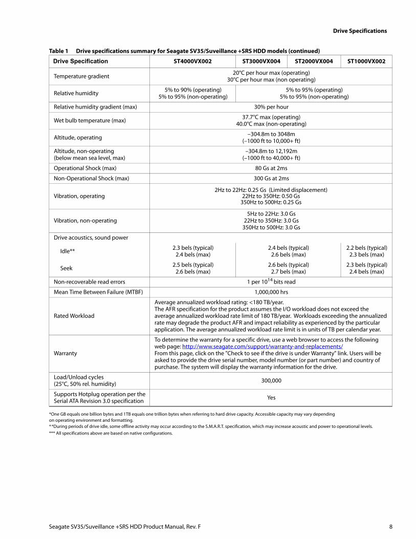
*One GB equals one billion bytes and 1TB equals one trillion bytes when referring to hard drive capacity. Accessible capacity may vary dependingon operating environment and formatting.**During periods of drive idle, some offline activity may occur according to the S.M.A.R.T. specification, which may increase acoustic and power to operational levels.*** All specifications above are based on native configurations.
Temperature gradient 20°C per hour max (operating)30°C per hour max (non operating)
Relative humidity 5% to 90% (operating)5% to 95% (non-operating)
5% to 95% (operating)5% to 95% (non-operating)
Relative humidity gradient (max) 30% per hour
Wet bulb temperature (max) 37.7°C max (operating)40.0°C max (non-operating)
Altitude, operating –304.8m to 3048m(–1000 ft to 10,000+ ft)
Altitude, non-operating (below mean sea level, max)
–304.8m to 12,192m(–1000 ft to 40,000+ ft)
Operational Shock (max) 80 Gs at 2ms
Non-Operational Shock (max) 300 Gs at 2ms
Vibration, operating2Hz to 22Hz: 0.25 Gs (Limited displacement)
22Hz to 350Hz: 0.50 Gs350Hz to 500Hz: 0.25 Gs
Vibration, non-operating5Hz to 22Hz: 3.0 Gs
22Hz to 350Hz: 3.0 Gs350Hz to 500Hz: 3.0 Gs
Drive acoustics, sound power
Idle** 2.3 bels (typical)2.4 bels (max)
2.4 bels (typical)2.6 bels (max)
2.2 bels (typical)2.3 bels (max)
Seek 2.5 bels (typical)2.6 bels (max)
2.6 bels (typical)2.7 bels (max)
2.3 bels (typical)2.4 bels (max)
Non-recoverable read errors 1 per 1014 bits read
Mean Time Between Failure (MTBF) 1,000,000 hrs
Rated Workload
Average annualized workload rating: <180 TB/year.The AFR specification for the product assumes the I/O workload does not exceed the average annualized workload rate limit of 180 TB/year. Workloads exceeding the annualized rate may degrade the product AFR and impact reliability as experienced by the particular application. The average annualized workload rate limit is in units of TB per calendar year.
Warranty
To determine the warranty for a specific drive, use a web browser to access the following web page: http://www.seagate.com/support/warranty-and-replacements/From this page, click on the "Check to see if the drive is under Warranty" link. Users will be asked to provide the drive serial number, model number (or part number) and country of purchase. The system will display the warranty information for the drive.
Load/Unload cycles(25°C, 50% rel. humidity) 300,000
Supports Hotplug operation per theSerial ATA Revision 3.0 specification Yes
Table 1 Drive specifications summary for Seagate SV35/Suveillance +SRS HDD models (continued)
Drive Specification ST4000VX002 ST3000VX004 ST2000VX004 ST1000VX002
Seagate SV35/Suveillance +SRS HDD Product Manual, Rev. F 8
Drive Specifications
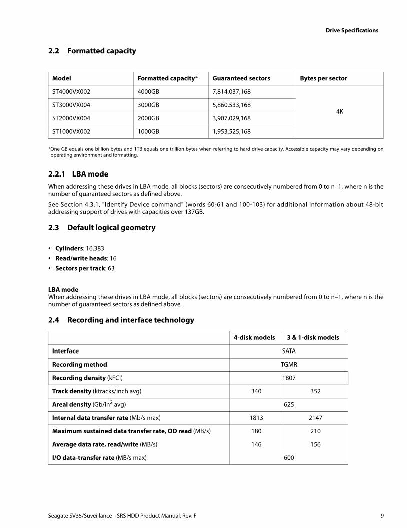
2.2 Formatted capacity
*One GB equals one billion bytes and 1TB equals one trillion bytes when referring to hard drive capacity. Accessible capacity may vary depending onoperating environment and formatting.
2.2.1 LBA modeWhen addressing these drives in LBA mode, all blocks (sectors) are consecutively numbered from 0 to n–1, where n is thenumber of guaranteed sectors as defined above.
See Section 4.3.1, "Identify Device command" (words 60-61 and 100-103) for additional information about 48-bitaddressing support of drives with capacities over 137GB.
2.3 Default logical geometry
• Cylinders: 16,383
• Read/write heads: 16
• Sectors per track: 63
LBA modeWhen addressing these drives in LBA mode, all blocks (sectors) are consecutively numbered from 0 to n–1, where n is thenumber of guaranteed sectors as defined above.
2.4 Recording and interface technology
Model Formatted capacity* Guaranteed sectors Bytes per sector
ST4000VX002 4000GB 7,814,037,168
4KST3000VX004 3000GB 5,860,533,168
ST2000VX004 2000GB 3,907,029,168
ST1000VX002 1000GB 1,953,525,168
4-disk models 3 & 1-disk models
Interface SATA
Recording method TGMR
Recording density (kFCI) 1807
Track density (ktracks/inch avg) 340 352
Areal density (Gb/in2 avg) 625
Internal data transfer rate (Mb/s max) 1813 2147
Maximum sustained data transfer rate, OD read (MB/s) 180 210
Average data rate, read/write (MB/s) 146 156
I/O data-transfer rate (MB/s max) 600
Seagate SV35/Suveillance +SRS HDD Product Manual, Rev. F 9
Drive Specifications
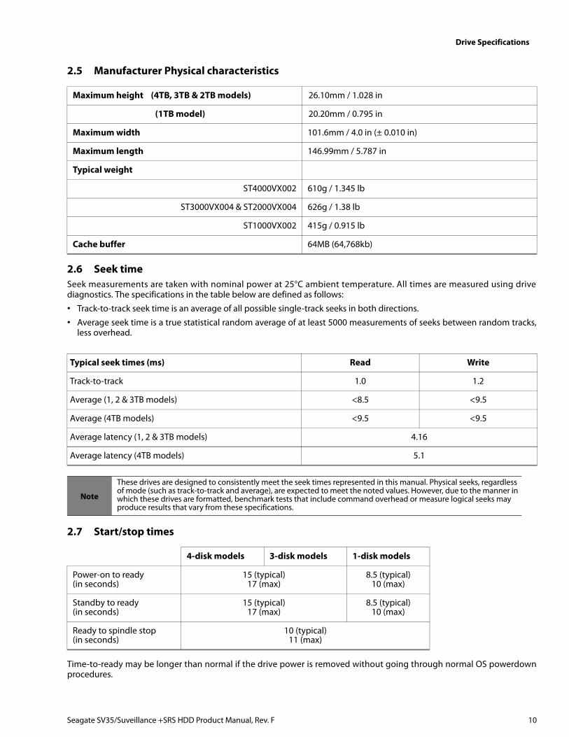
2.5 Manufacturer Physical characteristics
2.6 Seek timeSeek measurements are taken with nominal power at 25°C ambient temperature. All times are measured using drivediagnostics. The specifications in the table below are defined as follows:
• Track-to-track seek time is an average of all possible single-track seeks in both directions.
• Average seek time is a true statistical random average of at least 5000 measurements of seeks between random tracks,less overhead.
2.7 Start/stop times
Time-to-ready may be longer than normal if the drive power is removed without going through normal OS powerdownprocedures.
Maximum height (4TB, 3TB & 2TB models) 26.10mm / 1.028 in
(1TB model) 20.20mm / 0.795 in
Maximum width 101.6mm / 4.0 in (± 0.010 in)
Maximum length 146.99mm / 5.787 in
Typical weight
ST4000VX002 610g / 1.345 lb
ST3000VX004 & ST2000VX004 626g / 1.38 lb
ST1000VX002 415g / 0.915 lb
Cache buffer 64MB (64,768kb)
Typical seek times (ms) Read Write
Track-to-track 1.0 1.2
Average (1, 2 & 3TB models) <8.5 <9.5
Average (4TB models) <9.5 <9.5
Average latency (1, 2 & 3TB models) 4.16
Average latency (4TB models) 5.1
Note
These drives are designed to consistently meet the seek times represented in this manual. Physical seeks, regardless of mode (such as track-to-track and average), are expected to meet the noted values. However, due to the manner in which these drives are formatted, benchmark tests that include command overhead or measure logical seeks may produce results that vary from these specifications.
4-disk models 3-disk models 1-disk models
Power-on to ready(in seconds)
15 (typical)17 (max)
8.5 (typical)10 (max)
Standby to ready (in seconds)
15 (typical)17 (max)
8.5 (typical)10 (max)
Ready to spindle stop(in seconds)
10 (typical)11 (max)
Seagate SV35/Suveillance +SRS HDD Product Manual, Rev. F 10
Drive Specifications
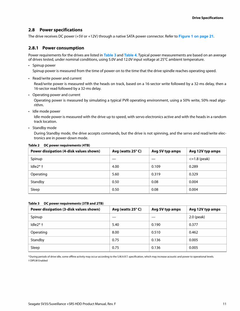
2.8 Power specificationsThe drive receives DC power (+5V or +12V) through a native SATA power connector. Refer to Figure 1 on page 21.
2.8.1 Power consumptionPower requirements for the drives are listed in Table 3 and Table 4. Typical power measurements are based on an averageof drives tested, under nominal conditions, using 5.0V and 12.0V input voltage at 25°C ambient temperature.
• Spinup powerSpinup power is measured from the time of power-on to the time that the drive spindle reaches operating speed.
• Read/write power and currentRead/write power is measured with the heads on track, based on a 16-sector write followed by a 32-ms delay, then a16-sector read followed by a 32-ms delay.
• Operating power and current Operating power is measured by simulating a typical PVR operating environment, using a 50% write, 50% read algo-rithm.
• Idle mode powerIdle mode power is measured with the drive up to speed, with servo electronics active and with the heads in a randomtrack location.
• Standby modeDuring Standby mode, the drive accepts commands, but the drive is not spinning, and the servo and read/write elec-tronics are in power-down mode.
*During periods of drive idle, some offline activity may occur according to the S.M.A.R.T. specification, which may increase acoustic and power to operational levels.† DIPLM Enabled
Table 2 DC power requirements (4TB)
Power dissipation (4-disk values shown) Avg (watts 25° C) Avg 5V typ amps Avg 12V typ amps
Spinup — — <=1.8 (peak)
Idle2* † 4.00 0.109 0.289
Operating 5.60 0.319 0.329
Standby 0.50 0.08 0.004
Sleep 0.50 0.08 0.004
Table 3 DC power requirements (3TB and 2TB)
Power dissipation (3-disk values shown) Avg (watts 25° C) Avg 5V typ amps Avg 12V typ amps
Spinup — — 2.0 (peak)
Idle2* † 5.40 0.190 0.377
Operating 8.00 0.510 0.462
Standby 0.75 0.136 0.005
Sleep 0.75 0.136 0.005
Seagate SV35/Suveillance +SRS HDD Product Manual, Rev. F 11
Drive Specifications
*During periods of drive idle, some offline activity may occur according to the S.M.A.R.T. specification, which may increase acoustic and power to operational levels.†DIPLM Enabled
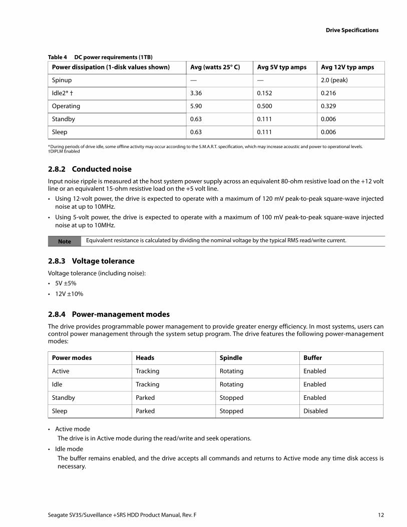
2.8.2 Conducted noiseInput noise ripple is measured at the host system power supply across an equivalent 80-ohm resistive load on the +12 voltline or an equivalent 15-ohm resistive load on the +5 volt line.
• Using 12-volt power, the drive is expected to operate with a maximum of 120 mV peak-to-peak square-wave injectednoise at up to 10MHz.
• Using 5-volt power, the drive is expected to operate with a maximum of 100 mV peak-to-peak square-wave injectednoise at up to 10MHz.
2.8.3 Voltage toleranceVoltage tolerance (including noise):
• 5V ±5%
• 12V ±10%
2.8.4 Power-management modesThe drive provides programmable power management to provide greater energy efficiency. In most systems, users cancontrol power management through the system setup program. The drive features the following power-managementmodes:
• Active modeThe drive is in Active mode during the read/write and seek operations.
• Idle modeThe buffer remains enabled, and the drive accepts all commands and returns to Active mode any time disk access isnecessary.
Table 4 DC power requirements (1TB)
Power dissipation (1-disk values shown) Avg (watts 25° C) Avg 5V typ amps Avg 12V typ amps
Spinup — — 2.0 (peak)
Idle2* † 3.36 0.152 0.216
Operating 5.90 0.500 0.329
Standby 0.63 0.111 0.006
Sleep 0.63 0.111 0.006
Note Equivalent resistance is calculated by dividing the nominal voltage by the typical RMS read/write current.
Power modes Heads Spindle Buffer
Active Tracking Rotating Enabled
Idle Tracking Rotating Enabled
Standby Parked Stopped Enabled
Sleep Parked Stopped Disabled
Seagate SV35/Suveillance +SRS HDD Product Manual, Rev. F 12
Drive Specifications
• Standby mode The drive enters Standby mode when the host sends a Standby Immediate command. If the host has set the standbytimer, the drive can also enter Standby mode automatically after the drive has been inactive for a specifiable length oftime. The standby timer delay is established using a Standby or Idle command. In Standby mode, the drive buffer isenabled, the heads are parked and the spindle is at rest. The drive accepts all commands and returns to Active modeany time disk access is necessary.
• Sleep modeThe drive enters Sleep mode after receiving a Sleep command from the host. In Sleep mode, the drive buffer is dis-abled, the heads are parked and the spindle is at rest. The drive leaves Sleep mode after it receives a Hard Reset or SoftReset from the host. After receiving a reset, the drive exits Sleep mode and enters Standby mode with all current trans-lation parameters intact.
• Idle and Standby timersEach time the drive performs an Active function (read, write or seek), the standby timer is reinitialized and beginscounting down from its specified delay times to zero. If the standby timer reaches zero before any drive activity isrequired, the drive makes a transition to Standby mode. In both Idle and Standby mode, the drive accepts all com-mands and returns to Active mode when disk access is necessary.
2.9 Environmental specifications
2.9.1 Ambient temperatureAmbient temperature is defined as the temperature of the environment immediately surrounding the drive. Actual drivecase temperature should not exceed 70°C (158°F) within the operating ambient conditions. Refer to Section 3.4 on page22 for base plate measurement location.
2.9.2 Temperature gradient
2.9.3 Humidity
2.9.3.1 Relative humidity
2.9.3.2 Wet bulb temperature
Operating 0° to 70°C (32° to 158°F)
Non-operating –40° to 70°C (–40° to 158°F)
Operating 20°C per hour (68°F per hour max), without condensation
Non-operating 30°C per hour (86°F per hour max)
Operating 5% to 95% non-condensing (30% per hour max)
Nonoperating 5% to 95% non-condensing (30% per hour max)
Operating 37.7°C (99.9°F max)
Non-operating 40°C (104°F max)
Seagate SV35/Suveillance +SRS HDD Product Manual, Rev. F 13
Drive Specifications
2.9.4 Altitude
2.9.5 ShockAll shock specifications assume that the drive is mounted securely with the input shock applied at the drive mountingscrews. Shock may be applied in the X, Y or Z axis.
2.9.5.1 Operating shock
These drives comply with the performance levels specified in this document when subjected to a maximum operatingshock of 80 Gs based on half-sine shock pulses of 2 ms during read operations. Shocks should not be repeated more thantwo times per second.
2.9.5.2 Non-operating shock
4TB, 3TB and 2TB models
The non-operating shock level that the drive can experience without incurring physical damage or degradation inperformance when subsequently put into operation is 300 Gs based on a non-repetitive half-sine shock pulse of 2 msduration.
1TB model
The non-operating shock level that the drive can experience without incurring physical damage or degradation inperformance when subsequently put into operation is 350 Gs based on a non-repetitive half-sine shock pulse of 2-msduration.
2.9.5.3 Operating vibration
The maximum vibration levels that the drive may experience while meeting the performance standards specified in thisdocument are specified below.
All vibration specifications assume that the drive is mounted securely with the input vibration applied at the drivemounting screws. Vibration may be applied in the X, Y or Z axis. Throughput may vary if improperly mounted.
2.9.6 Non-operating vibrationThe maximum non-operating vibration levels that the drive may experience without incurring physical damage ordegradation in performance when subsequently put into operation are specified below.
Operating –304.8m to 3048m (–1000 ft. to 10,000+ ft.)
Non-operating –304.8m to 12,192m (–1000 ft. to 40,000+ ft.)
2Hz to 22Hz 0.25 Gs (Limited displacement)
22Hz to 350Hz 0.50 Gs
350Hz to 500Hz 0.25 Gs
5Hz to 22Hz 3.0 Gs (Limited displacement)
22Hz to 350Hz 3.0 Gs
350Hz to 500Hz 3.0 Gs
Seagate SV35/Suveillance +SRS HDD Product Manual, Rev. F 14
Drive Specifications
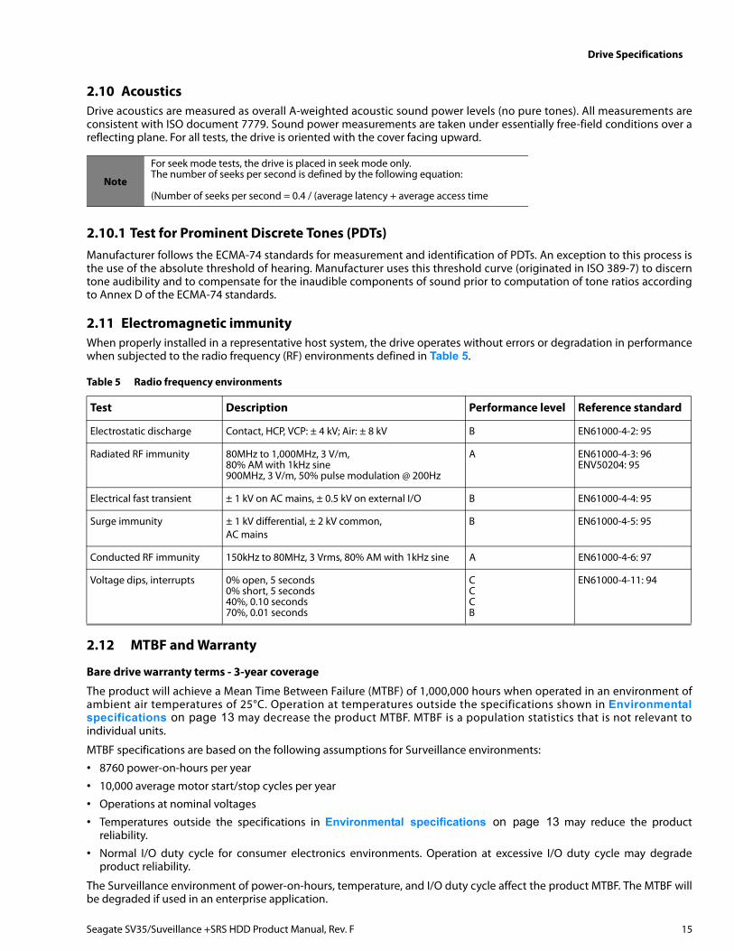
2.10 AcousticsDrive acoustics are measured as overall A-weighted acoustic sound power levels (no pure tones). All measurements areconsistent with ISO document 7779. Sound power measurements are taken under essentially free-field conditions over areflecting plane. For all tests, the drive is oriented with the cover facing upward.
2.10.1 Test for Prominent Discrete Tones (PDTs)Manufacturer follows the ECMA-74 standards for measurement and identification of PDTs. An exception to this process isthe use of the absolute threshold of hearing. Manufacturer uses this threshold curve (originated in ISO 389-7) to discerntone audibility and to compensate for the inaudible components of sound prior to computation of tone ratios accordingto Annex D of the ECMA-74 standards.
2.11 Electromagnetic immunityWhen properly installed in a representative host system, the drive operates without errors or degradation in performancewhen subjected to the radio frequency (RF) environments defined in Table 5.
2.12 MTBF and Warranty
Bare drive warranty terms - 3-year coverage
The product will achieve a Mean Time Between Failure (MTBF) of 1,000,000 hours when operated in an environment ofambient air temperatures of 25°C. Operation at temperatures outside the specifications shown in Environmentalspecifications on page 13 may decrease the product MTBF. MTBF is a population statistics that is not relevant toindividual units.
MTBF specifications are based on the following assumptions for Surveillance environments:
• 8760 power-on-hours per year
• 10,000 average motor start/stop cycles per year
• Operations at nominal voltages
• Temperatures outside the specifications in Environmental specifications on page 13 may reduce the productreliability.
• Normal I/O duty cycle for consumer electronics environments. Operation at excessive I/O duty cycle may degradeproduct reliability.
The Surveillance environment of power-on-hours, temperature, and I/O duty cycle affect the product MTBF. The MTBF willbe degraded if used in an enterprise application.
Note
For seek mode tests, the drive is placed in seek mode only. The number of seeks per second is defined by the following equation:
(Number of seeks per second = 0.4 / (average latency + average access time
Table 5 Radio frequency environments
Test Description Performance level Reference standard
Electrostatic discharge Contact, HCP, VCP: ± 4 kV; Air: ± 8 kV B EN61000-4-2: 95
Radiated RF immunity 80MHz to 1,000MHz, 3 V/m, 80% AM with 1kHz sine900MHz, 3 V/m, 50% pulse modulation @ 200Hz
A EN61000-4-3: 96ENV50204: 95
Electrical fast transient ± 1 kV on AC mains, ± 0.5 kV on external I/O B EN61000-4-4: 95
Surge immunity ± 1 kV differential, ± 2 kV common,AC mains
B EN61000-4-5: 95
Conducted RF immunity 150kHz to 80MHz, 3 Vrms, 80% AM with 1kHz sine A EN61000-4-6: 97
Voltage dips, interrupts 0% open, 5 seconds0% short, 5 seconds40%, 0.10 seconds70%, 0.01 seconds
CCCB
EN61000-4-11: 94
Seagate SV35/Suveillance +SRS HDD Product Manual, Rev. F 15
Drive Specifications
Seagate® Rescue™ Data Recovery Service – 3-year coverage (concurrent with bare drive warranty)
If you suffer a data loss event within the three year Seagate Rescue Data Recovery warranty period, and you are eligible toparticipate in and submit a case under the Rescue program, contact SRS at (1-800-723-1183) in the US, or if you are callingfrom outside the US please visit our website for numbers in your local and language: http://www.seagate.com/contacts/contact-numbers/.
In addition, you may visit http://rescueandreplace.seagate.com/contact.jsp to obtain information regarding how tocontact a recovery expert online or by telephone from your location. An SRS representative will review your case toconfirm your eligibility, and to assess whether your data may be recoverable by remote recovery services or whether youwill need to send your device to SRS for in-lab servicing.
Rescue™ General TermsThese Rescue™ General Terms together with the Rescue™ FAQ’s make up the Rescue™ Program Terms. By submitting a caseunder the Rescue™ program (“Program”) you agree to be bound by the Program Terms, including these General Terms andthe FAQ. You must be a legal resident of the US to participate in the Program.
Communications. All communications relating to your request will be available on our web site in your account and sentvia e-mail to the address you provide to us unless you request, in writing, to receive such communications via regular mail.
Personal Data. You must provide true, accurate and complete information about yourself as prompted by the requestform, including, without limitation, your name, address, e-mail address, and telephone number, as applicable (collectively,“Personal Data”). You must maintain and promptly update your Personal Data. You acknowledge that we may send youimportant information and notices regarding your requests by e-mail and that we shall have no liability associated with orarising from your failure to maintain accurate Personal Data.
Capacity; Legal Rights; Indemnity. You represent to SRS that you are of the legal age of majority in your state or countryof residence, with the full capacity to agree to these Program Terms. You warrant that you are the legal owner or theauthorized representative of the legal owner of the device you submit to SRS (the “Device”) and data. You warrant that thedata on the Device is legal and that you have the unrestricted legal right to (a) give us remote access to the data, (b) havethe data recovered and reproduced on a backup medium, (c) receive the recovered data, and (d) agree to these ProgramTerms. You will defend and indemnify us (including our directors, officers, employees, agents, delegates, and contractors)from any claims or actions relating to the Device or data, or your rights or lack of rights thereto.
Confidentiality. We will protect the confidentiality of your data against unauthorized disclosure using the same degree ofcare as we use to protect our own confidential information.
Disclaimer of Warranties, Representations and Guarantees. WE PROVIDE THE PROGRAM AND ANY SERVICESPROVIDED OR ATTEMPTED HEREUNDER “AS IS,” WITH ALL FAULTS, AT YOUR SOLE RISK. WE DO NOT EXTEND ANYEXPRESS WARRANTIES, REPRESENTATIONS, CONDITIONS OR GUARANTEES REGARDING OUR RESCUE SERVICES ORANY RESULTS THEREOF. TO THE MAXIMUM EXTENT PERMITTED BY APPLICABLE LAW AND SUBJECT TO ANYSTATUTORY WARRANTIES THAT CANNOT BE EXCLUDED, WE EXPRESSLY DISCLAIM ALL IMPLIED WARRANTIES,INCLUDING ANY IMPLIED WARRANTY OR CONDITION OF MERCHANTABILITY, WARRANTY OF FITNESS FOR APARTICULAR PURPOSE, OR WARRANTY OF ACCURACY OR COMPLETENESS WITH RESPECT TO THIS PROGRAM ANDSERVICES. This Program and Disclaimer is unrelated to, and does not affect any warranties relating to your Device that weor the seller may have extended to you.
Limitation of Liability. WE WILL NOT BE LIABLE FOR ANY HARM CAUSED, UNLESS YOU PROVE THAT WE CAUSEDSUCH HARM INTENTIONALLY. WITHOUT LIMITING THE GENERALITY OF THE FOREGOING, WE WILL NOT BE LIABLEFOR THE CONDITION, EXISTENCE, OR LOSS OF THE DATA YOU SEND US OR THE DATA WE RECOVER (IF ANY), ANYLOSS OF REVENUE OR LOSS OF PROFITS, OR ANY INDIRECT, SPECIAL, INCIDENTAL, OR CONSEQUENTIAL DAMAGESHOWEVER CAUSED. TO THE MAXIMUM EXTENT PERMITTED BY APPLICABLE LAW, THIS LIMITATION SHALL APPLYTO ANY AND ALL DAMAGES, REGARDLESS OF THE LEGAL THEORY ON WHICH THEY ARE ASSERTED (INCLUDING,WITHOUT LIMITATION, CONTRACT, BREACH OF CONTRACT, AND TORT), AND REGARDLESS OF WHETHER WE HAVEBEEN ADVISED OF THE POSSIBILITY OF LOSS OR DAMAGES - UNLESS YOU PROVE THAT SRS CAUSED DAMAGES TOYOU INTENTIONALLY. TO THE MAXIMUM EXTENT PERMITTED BY APPLICABLE LAW, THE AMOUNT OF OURLIABILITY WILL NOT EXCEED THE TOTAL PRICE YOU ACTUALLY PAY FOR THE DEVICE, THE ESSENTIAL PURPOSE OFWHICH IS TO LIMIT OUR LIABILITY ARISING FROM OR RELATED TO THE PROGRAM AND ANY DATA RECOVERYSERVICES. THIS ALLOCATION OF RISK IS REFLECTED IN THE PRICE CHARGED FOR THIS PROGRAM OR SERVICES, IFANY. YOU ACKNOWLEDGE THAT THE PRICE OF THIS PROGRAM WOULD BE MUCH GREATER IF WE UNDERTOOK
Seagate SV35/Suveillance +SRS HDD Product Manual, Rev. F 16

Drive Specifications
MORE EXTENSIVE LIABILITY. THIS PARAGRAPH WILL APPLY NOTWITHSTANDING ANY OTHER PROVISIONS IN THESETERMS, OR THE FAILURE OF ANY REMEDY.
Compliance with Laws. You agree to comply with all such laws and regulations and all other applicable laws, statutes,ordinances and regulations relating to the Program. You acknowledge that violations of these Program Terms couldsubject you to criminal or civil penalties. The goods licensed or provided, or services provided, through the Program,which may include technology and software, are subject to the customs and export control laws and regulations of theU.S. and may also be subject to the customs and export laws and regulations of the country in which the products aremanufactured or received. Further, under U.S. law, such goods may not be sold, leased or otherwise transferred torestricted countries, or used by a restricted end-user or an end-user engaged in activities related to weapons of massdestruction including, without limitation, activities related to designing, developing, producing or using nuclear weapons,materials, or facilities, missiles or supporting missile projects, or chemical or biological weapons. You acknowledge you arenot a restricted end-user or involved in any of the restricted activities above, and that you will comply with and abide bythese laws and regulations. Seagate reserves the right to refuse service to or the return of any storage devices that havebeen determined to violate these regulations.
Cancellation. You may cancel the Program at any time by contacting SRS at 1-800-SEAGATE (1-800-475-0143) in the US, orat such other number available at http://services.seagate.com/contact.aspx, or you simply may refrain from submitting arequest for Rescue services. These Program Terms remain applicable to your and SRS’s rights and obligations with respectto any services requested by you under this Program.
Assignment. You may not assign your rights or obligations under these Program Terms without SRS’ express writtenconsent.
Dispute Resolution. The parties will attempt to resolve any dispute arising out of or related to these Program Terms or anydata recovery services requested or attempted hereunder through good faith negotiation. To the extent permitted byapplicable law, if the parties are unable to resolve the dispute through good faith negotiation, then the dispute will besubmitted to final and binding arbitration with the Judicial Arbitration and Mediation Services. Each party will bear its owncosts in arbitration, provided that Seagate reserves the right, in its discretion, to pre-pay certain fees you may incur inconnection with the arbitration subject to refund if you do not prevail. Both parties waive their rights to a jury trial. Allproceedings will take place in Santa Clara County, California, USA. The laws of the State of California will exclusively governthese Program Terms and our provision of any data recovery services, without regard to California's conflicts of laws rules.You consent to the exclusive jurisdiction of the courts located in Santa Clara County, California, USA.
Severability. If any provision of these Program Terms is held invalid, illegal or unenforceable, such provision shall beenforced to the fullest extent permitted by applicable law and the validity, legality and enforceability of the remainingprovisions shall not be affected thereby.
Legal Effect. These Program Terms describe certain legal rights. You may have other rights under applicable law. TheseProgram Terms do not change your rights under applicable law if such laws do not permit these Program Terms to do so.Also, the Program and these Program Terms are in addition and unrelated to any rights you may have under a Seagatewarranty statement.
SRS Companies. The following SRS companies may provide the services described in these Program Terms: (a) SeagateTechnology LLC, with offices at 3101 Jay Street, Suite 110, Santa Clara, California 95054; (b) Seagate Technology CanadaInc., with offices at 2421 Bristol Circle, Suite A100, Oakville, Ontario, Canada L6H 5S9; and/or (c) Seagate Technology(Netherlands) B.V., with offices at Koolhovenlaan 1, 1119 PA, Schiphol-Rijk, The Netherlands.
Seagate SV35/Suveillance +SRS HDD Product Manual, Rev. F 17
Drive Specifications
2.13 Agency certification
2.13.1 Safety certificationThese products are certified to meet the requirements of UL60950-1, CSA60950-1 and EN60950 and so marked as to thecertify agency.
2.13.2 Electromagnetic compatibilityHard drives that display the CE mark comply with the European Union (EU) requirements specified in the ElectromagneticCompatibility Directive (2004/108/EC) as put into place 20 July 2007. Testing is performed to the levels specified by theproduct standards for Information Technology Equipment (ITE). Emission levels are defined by EN 55022, Class B and theimmunity levels are defined by EN 55024.
Drives are tested in representative end-user systems. Although CE-marked drives comply with the directives when used inthe test systems, we cannot guarantee that all systems will comply with the directives. The drive is designed for operationinside a properly designed enclosure, with properly shielded I/O cable (if necessary) and terminators on all unused I/Oports. Computer manufacturers and system integrators should confirm EMC compliance and provide CE marking for theirproducts.
Korean RRL
If these drives have the Korean Communications Commission (KCC) logo, they comply with paragraph 1 of Article 11 of theElectromagnetic Compatibility control Regulation and meet the Electromagnetic Compatibility (EMC) Frameworkrequirements of the Radio Research Laboratory (RRL) Communications Commission, Republic of Korea.
These drives have been tested and comply with the Electromagnetic Interference/Electromagnetic Susceptibility (EMI/EMS) for Class B products. Drives are tested in a representative, end-user system by a Korean-recognized lab.
• Family name: Surveillance HDD
• Certificate number: KCC-REM-STX-DesktopHDD
• Certification date: 2013-02-13
• Family name: SV35 HDD
• Certificate number: KCC-REM-STX-Barracuda
• Certification date: 2011-06-03
Australian C-Tick (N176)
If these models have the C-Tick marking, they comply with the Australia/New Zealand Standard AS/NZ CISPR22 and meetthe Electromagnetic Compatibility (EMC) Framework requirements of the Australian Communication Authority (ACA).
Seagate SV35/Suveillance +SRS HDD Product Manual, Rev. F 18
2.13.3 FCC verificationThese drives are intended to be contained solely within a personal computer or similar enclosure (not attached as anexternal device). As such, each drive is considered to be a subassembly even when it is individually marketed to thecustomer. As a subassembly, no Federal Communications Commission verification or certification of the device is required.
Seagate has tested this device in enclosures as described above to ensure that the total assembly (enclosure, disk drive,motherboard, power supply, etc.) does comply with the limits for a Class B computing device, pursuant to Subpart J, Part15 of the FCC rules. Operation with non-certified assemblies is likely to result in interference to radio and televisionreception.
Radio and television interference. This equipment generates and uses radio frequency energy and if not installed andused in strict accordance with the manufacturer’s instructions, may cause interference to radio and television reception.
This equipment is designed to provide reasonable protection against such interference in a residential installation.However, there is no guarantee that interference will not occur in a particular installation. If this equipment does causeinterference to radio or television, which can be determined by turning the equipment on and off, users are encouraged totry one or more of the following corrective measures:
• Reorient the receiving antenna.
• Move the device to one side or the other of the radio or TV.
• Move the device farther away from the radio or TV.
• Plug the computer into a different outlet so that the receiver and computer are on different branch outlets.
If necessary, users should consult the dealer or an experienced radio/television technician for additional suggestions.Users may find helpful the following booklet prepared by the Federal Communications Commission: How to Identify andResolve Radio-Television Interference Problems. This booklet is available from the Superintendent of Documents,U.S. Government Printing Office, Washington, DC 20402. Refer to publication number 004-000-00345-4.
Seagate SV35/Suveillance +SRS HDD Product Manual, Rev. F 19
Drive Specifications
2.14 Environmental protectionManufacturer designs its products to meet environmental protection requirements worldwide, including regulationsrestricting certain chemical substances.
2.14.1 European Union Restriction of Hazardous Substances (RoHS) DirectiveThe European Union Restriction of Hazardous Substances (RoHS) Directive, restricts the presence of chemical substances,including Lead, Cadmium, Mercury, Hexavalent Chromium, PBB and PBDE, in electronic products, effective July 2006. Thisdrive is manufactured with components and materials that comply with the RoHS Directive.
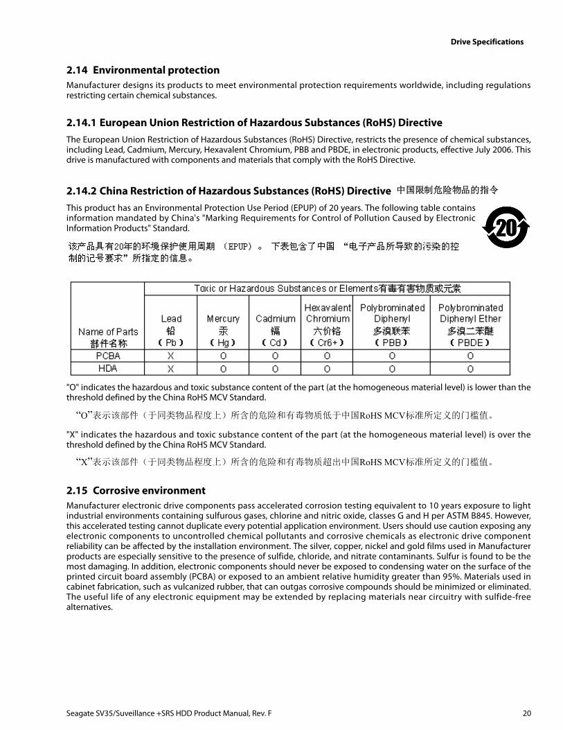
2.14.2 China Restriction of Hazardous Substances (RoHS) Directive This product has an Environmental Protection Use Period (EPUP) of 20 years. The following table containsinformation mandated by China's "Marking Requirements for Control of Pollution Caused by ElectronicInformation Products" Standard.
"O" indicates the hazardous and toxic substance content of the part (at the homogeneous material level) is lower than thethreshold defined by the China RoHS MCV Standard.
"X" indicates the hazardous and toxic substance content of the part (at the homogeneous material level) is over thethreshold defined by the China RoHS MCV Standard.
2.15 Corrosive environmentManufacturer electronic drive components pass accelerated corrosion testing equivalent to 10 years exposure to lightindustrial environments containing sulfurous gases, chlorine and nitric oxide, classes G and H per ASTM B845. However,this accelerated testing cannot duplicate every potential application environment. Users should use caution exposing anyelectronic components to uncontrolled chemical pollutants and corrosive chemicals as electronic drive componentreliability can be affected by the installation environment. The silver, copper, nickel and gold films used in Manufacturerproducts are especially sensitive to the presence of sulfide, chloride, and nitrate contaminants. Sulfur is found to be themost damaging. In addition, electronic components should never be exposed to condensing water on the surface of theprinted circuit board assembly (PCBA) or exposed to an ambient relative humidity greater than 95%. Materials used incabinet fabrication, such as vulcanized rubber, that can outgas corrosive compounds should be minimized or eliminated.The useful life of any electronic equipment may be extended by replacing materials near circuitry with sulfide-freealternatives.
中国限制危险物品的指令
“O”表示该部件(于同类物品程度上)所含的危险和有毒物质低于中国RoHS MCV标准所定义的门槛值。
“X”表示该部件(于同类物品程度上)所含的危险和有毒物质超出中国RoHS MCV标准所定义的门槛值。
Seagate SV35/Suveillance +SRS HDD Product Manual, Rev. F 20
Configuring and Mounting the Drive
3.0 Configuring and Mounting the Drive
This section contains the specifications and instructions for configuring and mounting the drive.
3.1 Handling and static-discharge precautionsAfter unpacking, and before installation, the drive may be exposed to potential handling and electrostatic discharge (ESD)hazards. Observe the following standard handling and static-discharge precautions:
Caution
• Before handling the drive, put on a grounded wrist strap, or ground yourself frequently by touching the metal chassis ofa computer that is plugged into a grounded outlet. Wear a grounded wrist strap throughout the entire installationprocedure.
• Handle the drive by its edges or frame only.
• The drive is extremely fragile—handle it with care. Do not press down on the drive top cover.
• Always rest the drive on a padded, antistatic surface until mounting it in the computer.
• Do not touch the connector pins or the printed circuit board.
• Do not remove the factory-installed labels from the drive or cover them with additional labels. Removal voids thewarranty. Some factory-installed labels contain information needed to service the drive. Other labels are used to sealout dirt and contamination.
3.2 Configuring the driveEach drive on the SATA interface connects point-to-point with the SATA host adapter. There is no master/slave relationshipbecause each drive is considered a master in a point-to-point relationship. If two drives are attached on one SATA hostadapter, the host operating system views the two devices as if they were both “masters” on two separate ports. Both drivesbehave as if they are Device 0 (master) devices.
SATA drives are designed for easy installation. It is usually not necessary to set any jumpers on the drive for properoperation; however, if users connect the drive and receive a “drive not detected” error, the SATA-equipped motherboard orhost adapter may use a chipset that does not support SATA speed autonegotiation.
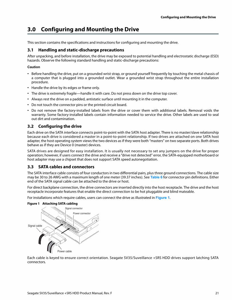
3.3 SATA cables and connectorsThe SATA interface cable consists of four conductors in two differential pairs, plus three ground connections. The cable sizemay be 30 to 26 AWG with a maximum length of one meter (39.37 inches). See Table 6 for connector pin definitions. Eitherend of the SATA signal cable can be attached to the drive or host.
For direct backplane connection, the drive connectors are inserted directly into the host receptacle. The drive and the hostreceptacle incorporate features that enable the direct connection to be hot pluggable and blind mateable.
For installations which require cables, users can connect the drive as illustrated in Figure 1.
Figure 1 Attaching SATA cabling
Each cable is keyed to ensure correct orientation. Seagate SV35/Suveillance +SRS HDD drives support latching SATAconnectors.
Power cable
Signal cable
Signal connector
Power connector
Seagate SV35/Suveillance +SRS HDD Product Manual, Rev. F 21
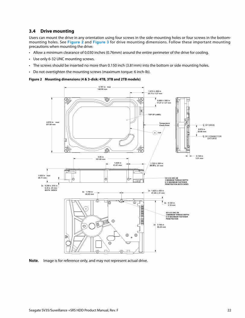
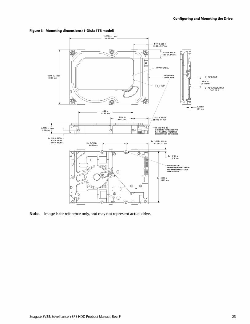
3.4 Drive mountingUsers can mount the drive in any orientation using four screws in the side-mounting holes or four screws in the bottom-mounting holes. See Figure 2 and Figure 3 for drive mounting dimensions. Follow these important mountingprecautions when mounting the drive:
• Allow a minimum clearance of 0.030 inches (0.76mm) around the entire perimeter of the drive for cooling.
• Use only 6-32 UNC mounting screws.
• The screws should be inserted no more than 0.150 inch (3.81mm) into the bottom or side mounting holes.
• Do not overtighten the mounting screws (maximum torque: 6 inch-lb).
Figure 2 Mounting dimensions (4 & 3-disk: 4TB, 3TB and 2TB models)
Note. Image is for reference only, and may not represent actual drive.
TOP OF LABEL
5 TYP
3X 6-32 UNC-2B3 MINIMUM THREAD DEPTH0.15 MAXIMUM FASTENERPENETRATION BOTH SIDES
4X 6-32 UNC-2B3 MINIMUM THREAD DEPTH0.15 MAXIMUM FASTENERPENETRATION
CL OF DRIVE
CL OF CONNECTORDATUM B
5.787 in max146.99 mm
4.010 in max101.85 mm
2x 1.625 ± .020 in 41.28 ± .51 mm2x 1.750 in
44.45 mm
2x 0.125 in 3.18 mm
4.00 in101.60 mm
1.638 in41.61 mm
1.122 ± .020 in 30.99 ± .51 mm
0.138 in3.51 mm
0.814 in20.68 mm
1.028 in max26.11 mm
3x 0.250 ± .010 in 6.35 ± .25 mm BOTH SIDES
2x 3.750 in 95.25 mm
1.013 ± .050 in25.73 ± 1.27 mm
0.680 ± .050 in17.27 ± 1.27 mm
TemperatureCheck Point
28.50
Seagate SV35/Suveillance +SRS HDD Product Manual, Rev. F 22
Configuring and Mounting the Drive
Figure 3 Mounting dimensions (1-Disk: 1TB model)
Note. Image is for reference only, and may not represent actual drive.
5 TYP
TOP OF LABEL
CL OF CONNECTORDATUM B
CL OF DRIVE
3X 6-32 UNC-2B3 MINIMUM THREAD DEPTH0.15 MAXIMUM FASTENERPENETRATION BOTH SIDES
4X 6-32 UNC-2B3 MINIMUM THREAD DEPTH0.15 MAXIMUM FASTENERPENETRATION
5.787 in. max146.99 mm
4.010 in. max101.85 mm
0.787 in. max19.99 mm
3x .250 ± .010in 6.35 ± .25mm BOTH SIDES
4.00 in101.60 mm
1.638 in41.61 mm
1.122 ± .020 in 30.99 ± .51 mm
2x 1.625 ± .020 in 41.28 ± .51 mm2x 1.750 in
44.45 mm
2x 3.750 in 95.25 mm
2x 0.125 in 3.18 mm
1.106 ± .050 in28.09 ± 1.27 mm
0.626 ± .050 in15.90 ± 1.27 mm
TemperatureCheck Point
0.814 in20.68 mm
0.138 in3.51 mm
28.50
Seagate SV35/Suveillance +SRS HDD Product Manual, Rev. F 23
SATA Interface
4.0 SATA Interface
These drives use the industry-standard Serial ATA (SATA) interface that supports FIS data transfers. It supports ATAprogrammed input/output (PIO) modes 0 to 4; multiword DMA modes 0 to 2, and Ultra DMA modes 0 to 6.
For detailed information about the SATA interface, refer to the “Serial ATA: High Speed Serialized AT Attachment”specification.
4.1 Hot-Plug compatibilitySeagate SV35/Suveillance +SRS HDD drives incorporate connectors which enable users to hot plug these drives inaccordance with the SATA Revision 2.5 specification. This specification can be downloaded from www.serialata.org.
4.2 SATA device plug connector pin definitionsTable 6 summarizes the signals on the SATA interface and power connectors.
Notes1. All pins are in a single row, with a 1.27 mm (0.050”) pitch.
2. The comments on the mating sequence apply to the case of backplane blindmate connector only. In this case, themating sequences are:
• the ground pins P4 and P12.• the pre-charge power pins and the other ground pins.• the signal pins and the rest of the power pins.
3. There are three power pins for each voltage. One pin from each voltage is used for pre-charge when installed in ablind-mate backplane configuration.
• All used voltage pins (Vx) must be terminated.
Table 6 SATA connector pin definitions
Segment Pin Function Definition
Signal
S1 Ground 2nd mate
S2 A+Differential signal pair A from Phy
S3 A-
S4 Ground 2nd mate
S5 B-Differential signal pair B from Phy
S6 B+
S7 Ground 2nd mate
Key and spacing separate signal and power segments
Power
P1 V33 3.3V power
P2 V33 3.3V power
P3 V33 3.3V power, pre-charge, 2nd mate
P4 Ground 1st mate
P5 Ground 2nd mate
P6 Ground 2nd mate
P7 V5 5V power, pre-charge, 2nd mate
P8 V5 5V power
P9 V5 5V power
P10 Ground 2nd mate
P11 Ground or LED signal If grounded, drive does not use deferred spin
P12 Ground 1st mate.
P13 V12 12V power, pre-charge, 2nd mate
P14 V12 12V power
P15 V12 12V power
Seagate SV35/Suveillance +SRS HDD Product Manual, Rev. F 24
SATA Interface
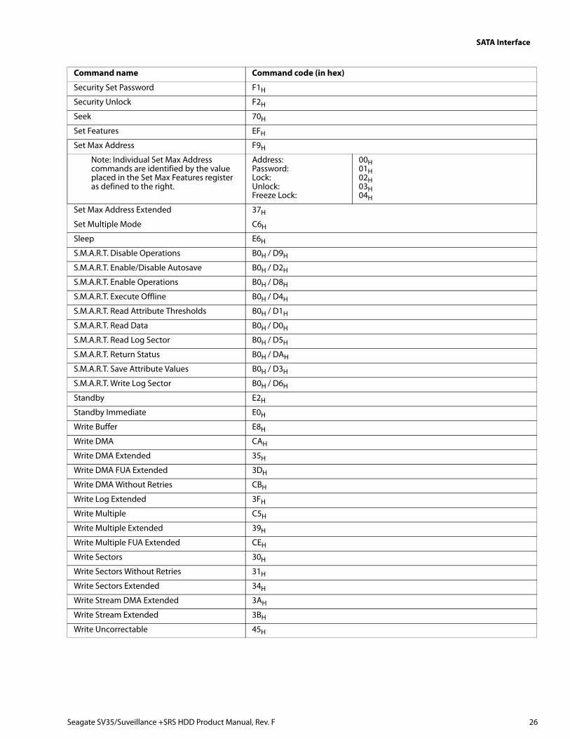
4.3 Supported ATA commandsThe following table lists SATA standard commands that the drive supports.For a detailed description of the ATA commands, refer to the Serial ATA International Organization:Serial ATA Revision 3.0 (http://www.sata-io.org).
See “S.M.A.R.T. commands” on page 32 for details and subcommands used in the S.M.A.R.T. implementation.
Command name Command code (in hex)
Check Power Mode E5H
Configure Stream 51H
Device Configuration Freeze Lock B1H / C1H
Device Configuration Identify B1H / C2H
Device Configuration Restore B1H / C0H
Device Configuration Set B1H / C3H
Device Reset 08H
Download Microcode 92H
Execute Device Diagnostics 90H
Flush Cache E7H
Flush Cache Extended EAH
Format Track 50H
Identify Device ECH
Idle E3H
Idle Immediate E1H
Initialize Device Parameters 91H
Read Buffer E4H
Read DMA C8H
Read DMA Extended 25H
Read DMA Without Retries C9H
Read Log Ext 2FH
Read Multiple C4H
Read Multiple Extended 29H
Read Native Max Address F8H
Read Native Max Address Extended 27H
Read Sectors 20H
Read Sectors Extended 24H
Read Sectors Without Retries 21H
Read Stream DMA Extended 2AH
Read Stream Extended 2BH
Read Verify Sectors 40H
Read Verify Sectors Extended 42H
Read Verify Sectors Without Retries 41H
Recalibrate 10H
Security Disable Password F6H
Security Erase Prepare F3H
Security Erase Unit F4H
Security Freeze F5H
Seagate SV35/Suveillance +SRS HDD Product Manual, Rev. F 25
SATA Interface
Security Set Password F1H
Security Unlock F2H
Seek 70H
Set Features EFH
Set Max Address F9H
Note: Individual Set Max Address commands are identified by the value placed in the Set Max Features register as defined to the right.
Address:Password:Lock:Unlock:Freeze Lock:
00H01H02H03H04H
Set Max Address Extended 37H
Set Multiple Mode C6H
Sleep E6H
S.M.A.R.T. Disable Operations B0H / D9H
S.M.A.R.T. Enable/Disable Autosave B0H / D2H
S.M.A.R.T. Enable Operations B0H / D8H
S.M.A.R.T. Execute Offline B0H / D4H
S.M.A.R.T. Read Attribute Thresholds B0H / D1H
S.M.A.R.T. Read Data B0H / D0H
S.M.A.R.T. Read Log Sector B0H / D5H
S.M.A.R.T. Return Status B0H / DAH
S.M.A.R.T. Save Attribute Values B0H / D3H
S.M.A.R.T. Write Log Sector B0H / D6H
Standby E2H
Standby Immediate E0H
Write Buffer E8H
Write DMA CAH
Write DMA Extended 35H
Write DMA FUA Extended 3DH
Write DMA Without Retries CBH
Write Log Extended 3FH
Write Multiple C5H
Write Multiple Extended 39H
Write Multiple FUA Extended CEH
Write Sectors 30H
Write Sectors Without Retries 31H
Write Sectors Extended 34H
Write Stream DMA Extended 3AH
Write Stream Extended 3BH
Write Uncorrectable 45H
Command name Command code (in hex)
Seagate SV35/Suveillance +SRS HDD Product Manual, Rev. F 26
SATA Interface
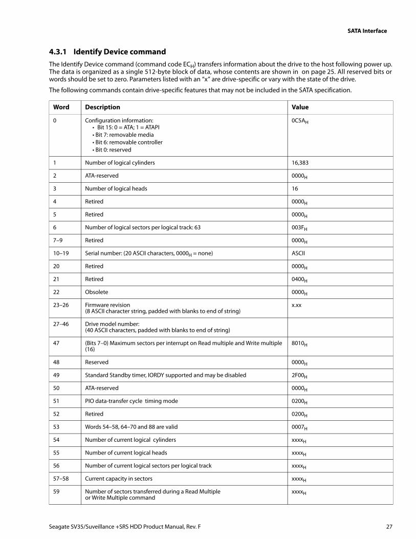
4.3.1 Identify Device commandThe Identify Device command (command code ECH) transfers information about the drive to the host following power up.The data is organized as a single 512-byte block of data, whose contents are shown in on page 25. All reserved bits orwords should be set to zero. Parameters listed with an “x” are drive-specific or vary with the state of the drive.
The following commands contain drive-specific features that may not be included in the SATA specification.
Word Description Value
0 Configuration information:• Bit 15: 0 = ATA; 1 = ATAPI• Bit 7: removable media• Bit 6: removable controller• Bit 0: reserved
0C5AH
1 Number of logical cylinders 16,383
2 ATA-reserved 0000H
3 Number of logical heads 16
4 Retired 0000H
5 Retired 0000H
6 Number of logical sectors per logical track: 63 003FH
7–9 Retired 0000H
10–19 Serial number: (20 ASCII characters, 0000H = none) ASCII
20 Retired 0000H
21 Retired 0400H
22 Obsolete 0000H
23–26 Firmware revision(8 ASCII character string, padded with blanks to end of string)
x.xx
27–46 Drive model number:(40 ASCII characters, padded with blanks to end of string)
47 (Bits 7–0) Maximum sectors per interrupt on Read multiple and Write multiple (16)
8010H
48 Reserved 0000H
49 Standard Standby timer, IORDY supported and may be disabled 2F00H
50 ATA-reserved 0000H
51 PIO data-transfer cycle timing mode 0200H
52 Retired 0200H
53 Words 54–58, 64–70 and 88 are valid 0007H
54 Number of current logical cylinders xxxxH
55 Number of current logical heads xxxxH
56 Number of current logical sectors per logical track xxxxH
57–58 Current capacity in sectors xxxxH
59 Number of sectors transferred during a Read Multiple or Write Multiple command
xxxxH
Seagate SV35/Suveillance +SRS HDD Product Manual, Rev. F 27
SATA Interface
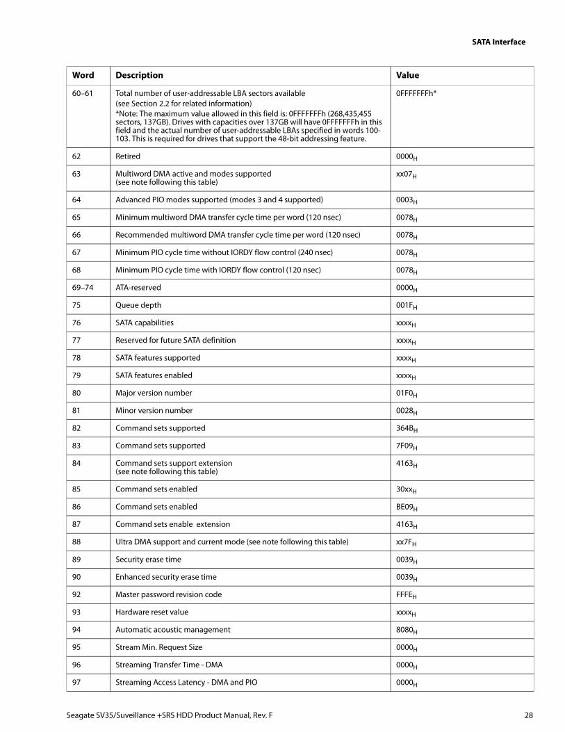
60–61 Total number of user-addressable LBA sectors available(see Section 2.2 for related information)*Note: The maximum value allowed in this field is: 0FFFFFFFh (268,435,455 sectors, 137GB). Drives with capacities over 137GB will have 0FFFFFFFh in this field and the actual number of user-addressable LBAs specified in words 100-103. This is required for drives that support the 48-bit addressing feature.
0FFFFFFFh*
62 Retired 0000H
63 Multiword DMA active and modes supported(see note following this table)
xx07H
64 Advanced PIO modes supported (modes 3 and 4 supported) 0003H
65 Minimum multiword DMA transfer cycle time per word (120 nsec) 0078H
66 Recommended multiword DMA transfer cycle time per word (120 nsec) 0078H
67 Minimum PIO cycle time without IORDY flow control (240 nsec) 0078H
68 Minimum PIO cycle time with IORDY flow control (120 nsec) 0078H
69–74 ATA-reserved 0000H
75 Queue depth 001FH
76 SATA capabilities xxxxH
77 Reserved for future SATA definition xxxxH
78 SATA features supported xxxxH
79 SATA features enabled xxxxH
80 Major version number 01F0H
81 Minor version number 0028H
82 Command sets supported 364BH
83 Command sets supported 7F09H
84 Command sets support extension(see note following this table)
4163H
85 Command sets enabled 30xxH
86 Command sets enabled BE09H
87 Command sets enable extension 4163H
88 Ultra DMA support and current mode (see note following this table) xx7FH
89 Security erase time 0039H
90 Enhanced security erase time 0039H
92 Master password revision code FFFEH
93 Hardware reset value xxxxH
94 Automatic acoustic management 8080H
95 Stream Min. Request Size 0000H
96 Streaming Transfer Time - DMA 0000H
97 Streaming Access Latency - DMA and PIO 0000H
Word Description Value
Seagate SV35/Suveillance +SRS HDD Product Manual, Rev. F 28
SATA Interface
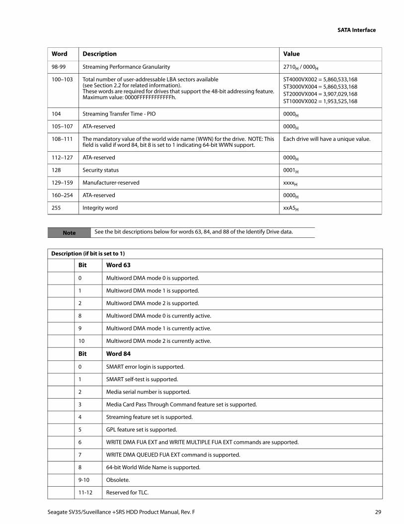
98-99 Streaming Performance Granularity 2710H / 0000H
100–103 Total number of user-addressable LBA sectors available(see Section 2.2 for related information).These words are required for drives that support the 48-bit addressing feature. Maximum value: 0000FFFFFFFFFFFFh.
ST4000VX002 = 5,860,533,168ST3000VX004 = 5,860,533,168ST2000VX004 = 3,907,029,168ST1000VX002 = 1,953,525,168
104 Streaming Transfer Time - PIO 0000H
105–107 ATA-reserved 0000H
108–111 The mandatory value of the world wide name (WWN) for the drive. NOTE: This field is valid if word 84, bit 8 is set to 1 indicating 64-bit WWN support.
Each drive will have a unique value.
112–127 ATA-reserved 0000H
128 Security status 0001H
129–159 Manufacturer-reserved xxxxH
160–254 ATA-reserved 0000H
255 Integrity word xxA5H
Note See the bit descriptions below for words 63, 84, and 88 of the Identify Drive data.
Description (if bit is set to 1)
Bit Word 63
0 Multiword DMA mode 0 is supported.
1 Multiword DMA mode 1 is supported.
2 Multiword DMA mode 2 is supported.
8 Multiword DMA mode 0 is currently active.
9 Multiword DMA mode 1 is currently active.
10 Multiword DMA mode 2 is currently active.
Bit Word 84
0 SMART error login is supported.
1 SMART self-test is supported.
2 Media serial number is supported.
3 Media Card Pass Through Command feature set is supported.
4 Streaming feature set is supported.
5 GPL feature set is supported.
6 WRITE DMA FUA EXT and WRITE MULTIPLE FUA EXT commands are supported.
7 WRITE DMA QUEUED FUA EXT command is supported.
8 64-bit World Wide Name is supported.
9-10 Obsolete.
11-12 Reserved for TLC.
Word Description Value
Seagate SV35/Suveillance +SRS HDD Product Manual, Rev. F 29
SATA Interface
13 IDLE IMMEDIATE command with IUNLOAD feature is supported.
14 Shall be set to 1.
15 Shall be cleared to 0.
Bit Word 88
0 Ultra DMA mode 0 is supported.
1 Ultra DMA mode 1 is supported.
2 Ultra DMA mode 2 is supported.
3 Ultra DMA mode 3 is supported.
4 Ultra DMA mode 4 is supported.
5 Ultra DMA mode 5 is supported.
6 Ultra DMA mode 6 is supported.
8 Ultra DMA mode 0 is currently active.
9 Ultra DMA mode 1 is currently active.
10 Ultra DMA mode 2 is currently active.
11 Ultra DMA mode 3 is currently active.
12 Ultra DMA mode 4 is currently active.
13 Ultra DMA mode 5 is currently active.
14 Ultra DMA mode 6 is currently active.
Seagate SV35/Suveillance +SRS HDD Product Manual, Rev. F 30
SATA Interface
4.3.2 Set Features commandThis command controls the implementation of various features that the drive supports. When the drive receives thiscommand, it sets BSY, checks the contents of the Features register, clears BSY and generates an interrupt. If the value in theregister does not represent a feature that the drive supports, the command is aborted. Power-on default has the read look-ahead and write caching features enabled. The acceptable values for the Features register are defined as follows:
02H Enable write cache (default).
03H Set transfer mode (based on value in Sector Count register).Sector Count register values:
00H Set PIO mode to default (PIO mode 2).
01H Set PIO mode to default and disable IORDY (PIO mode 2).
08H PIO mode 0
09H PIO mode 1
0AH PIO mode 2
0BH PIO mode 3
0CH PIO mode 4 (default)
20H Multiword DMA mode 0
21H Multiword DMA mode 1
22H Multiword DMA mode 2
40H Ultra DMA mode 0
41H Ultra DMA mode 1
42H Ultra DMA mode 2
43H Ultra DMA mode 3
44H Ultra DMA mode 4
45H Ultra DMA mode 5
46H Ultra DMA mode 6
10H Enable use of SATA features
55H Disable read look-ahead (read cache) feature.
82H Disable write cache
90H Disable use of SATA features
AAH Enable read look-ahead (read cache) feature (default).
F1H Report full capacity available
Note At power-on, or after a hardware or software reset, the default values of the features are as indicated above.
Seagate SV35/Suveillance +SRS HDD Product Manual, Rev. F 31
SATA Interface
4.3.3 S.M.A.R.T. commandsS.M.A.R.T. provides near-term failure prediction for disk drives. When S.M.A.R.T. is enabled, the drive monitorspredetermined drive attributes that are susceptible to degradation over time. If self-monitoring determines that a failure islikely, S.M.A.R.T. makes a status report available to the host. Not all failures are predictable. S.M.A.R.T. predictability islimited to the attributes the drive can monitor. For more information on S.M.A.R.T. commands and implementation, see theDraft ATA-5 Standard.
Diagnostic software activates a built-in drive self-test (DST S.M.A.R.T. command for D4H) that eliminates unnecessary drivereturns. The diagnostic software ships with all new drives.
This drive is shipped with S.M.A.R.T. features disabled. Users must have a recent BIOS or software package that supportsS.M.A.R.T. to enable this feature. The table below shows the S.M.A.R.T. command codes that the drive uses.
Code in features register S.M.A.R.T. command
D0H S.M.A.R.T. Read Data
D2H S.M.A.R.T. Enable/Disable Attribute Autosave
D3H S.M.A.R.T. Save Attribute Values
D4H S.M.A.R.T. Execute Off-line Immediate (runs DST)
D5H S.M.A.R.T. Read Log Sector
D6H S.M.A.R.T. Write Log Sector
D8H S.M.A.R.T. Enable Operations
D9H S.M.A.R.T. Disable Operations
DAH S.M.A.R.T. Return Status
NoteIf an appropriate code is not written to the Features Register, the command is aborted and 0x04 (abort) is written to the Error register.
Seagate SV35/Suveillance +SRS HDD Product Manual, Rev. F 32
Seagate Technology LLCAMERICAS Seagate Technology LLC 10200 South De Anza Boulevard, Cupertino, California 95014, United States, 408-658-1000ASIA/PACIFIC Seagate Singapore International Headquarters Pte. Ltd. 7000 Ang Mo Kio Avenue 5, Singapore 569877, 65-6485-3888EUROPE, MIDDLE EAST AND AFRICA Seagate Technology SAS 16-18 rue du Dôme, 92100 Boulogne-Billancourt, France, 33 1-4186 10 00
Publication Number: 100759604, Rev. F September 2015
Recommended