Embed Size (px)
Citation preview

Scheimpflug Imaging
ORBSCAN & PENTACAM
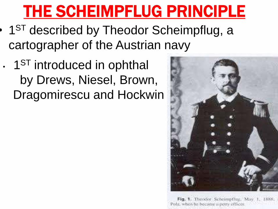
THE SCHEIMPFLUG PRINCIPLE• 1ST described by Theodor Scheimpflug, a
cartographer of the Austrian navy
• 1ST introduced in ophthal
by Drews, Niesel, Brown,
Dragomirescu and Hockwin
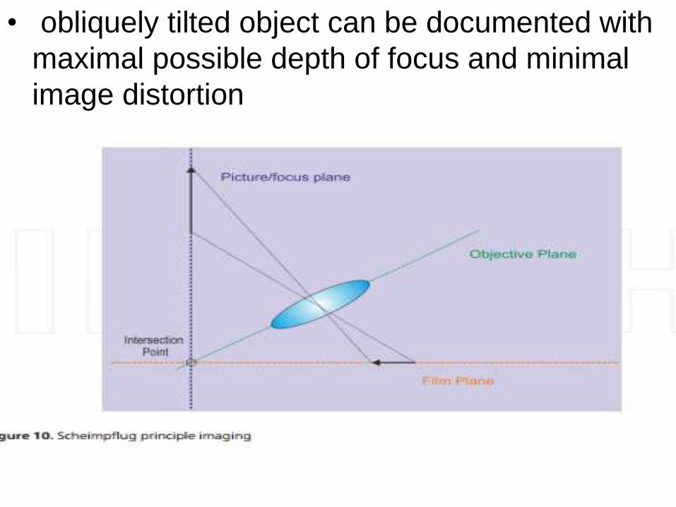
• obliquely tilted object can be documented with
maximal possible depth of focus and minimal
image distortion
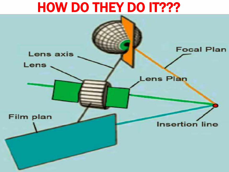
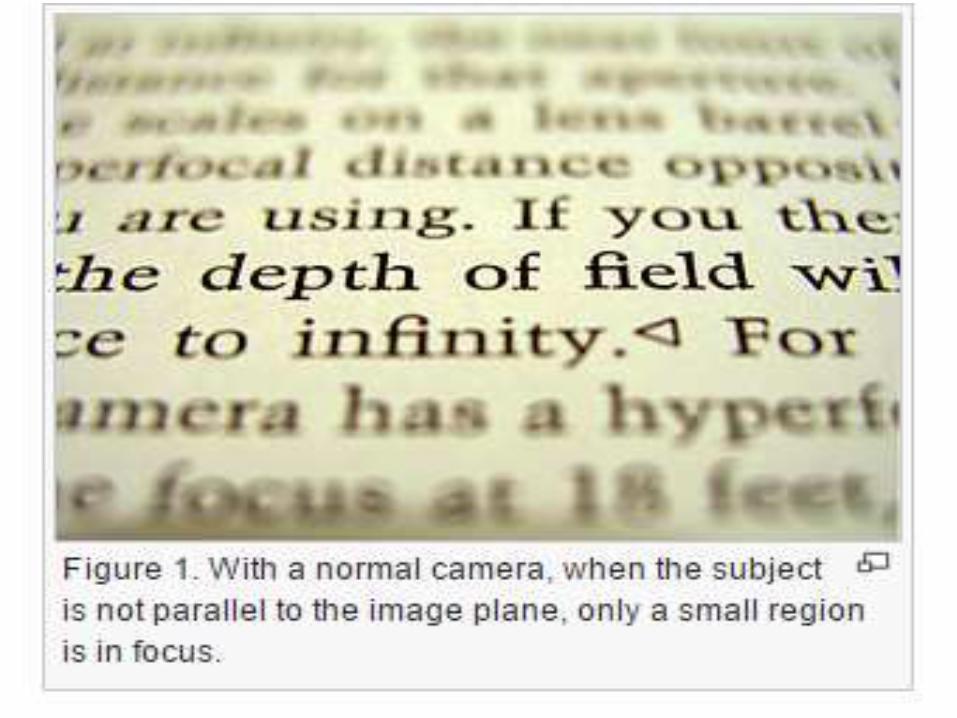
HOW DO THEY DO IT???• 3 imaginary planes -film, lens and focal
plane(non-parallel ).
• Tilt the lens plane of the lens intercept the
planes of the film and focus in a line of
intersection known as Scheimpflug linedepth
of focus,sharpness of image points located on
different planes are high.
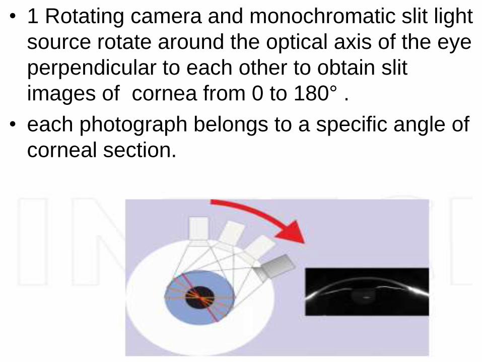
• 1 Rotating camera and monochromatic slit light
source rotate around the optical axis of the eye
perpendicular to each other to obtain slit
images of cornea from 0 to 180° .
• each photograph belongs to a specific angle of
corneal section.
• A 2nd center placed static camera captures and
corrects eye movements pupil diameter &
corrects,
• Software :construct 3D model of AS from
25,000 data points
• calculates data for corneal
topography,thickness,ACD,lens opacification
and thickness,corneal wavefront of the anterior
and posterior corneal surface using Zernike
polynomials .
THE SCHEIMPFLUG SYSTEM • Images the anterior eye with a camera at an angle to a
slit-beam creating an optic section of the cornea and
lens.
• USES• For the assessment of :
keratoconus
cataract
IOL tilt
IOL decentration
corneal clearance
posterior subcapsular opacification
shape changes with accommodation,corneal implants
corneal thickness and anterior chamber depth

• NONCONTACT IMAGING OF AS
a and p surface topography of the cornea .
anterior chamber biometry.
keratometry.
pachymetry mapping.
• PRE OP EVALUATION IN REFRACTIVE SX
Cases @ risk of ectasia.
planning & evaluation of results of sx .
• IN FEMTOSECOND LASER-ASSISTED
CATARACT Sx
• corneal thickness, elevation, curvature, anterior
chamber depth, or refractive power in color
map of the physician’s choice
SCHEIMPFLUG SYSTEMS• 4 devices using the Scheimpflug principle &
camera:
• TMS-5 (Tomey, Nagoya,Japan),
• Pentacam® HR (OCULUS, Wetzlar, Germany),
• Sirius® (CSO,Florence, Italy),
• Galilei® (Ziemer, Port, Switzerland)
ORBSCAN(ORBTEK, INC.) 1995
• slit-scanning corneal topographer
• true elevation maps of A & P corneal surfaces.
• pachymetry of the entire cornea.
• Anterior change depth.
• Pupil size and white to white measurement.
ORBSCAN II (BAUSCH & LOMB).
• placido system to give conventional
topographical maps + orbscan.
• IMAGING:slit scanning /cobble stone
methodology with 40 slits of h8 12.5 mm & 0.3
mm width ,schleimflug angle 45⁰.
Advantages of orbscan
• quantity of information superior.
Disadvantages of orbscan
• it is more expensive than placido systems.
• It has a slower image capture (2-3 s vs 0.5 s).
• orbscan II is not validated against a gold standard.
Indications
1. Detect KC ,ectatic corneal diseases.
2. Screen forme fruste KC,CL warpage b4 refractive sx.
3. Measure regular and irregular astigmatism.
4. Aid in planning refractive surgery.
5. Measure optical zone sizes, centration,changes
after keratorefractive sx & orthokeratology.
6. Aid suture removal after PK.
7. Guide CL fitting in advanced KC .
8. Pachymetry.
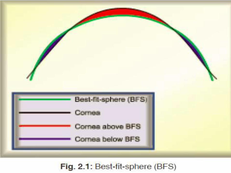
• Interpretation of Orbscan Maps
• printout :quad map ( 4 maps).
1. elevation maps
-anterior float & posterior float.
-the measured surface vs reference sphere .
-cornea tissue above reference sphere :warm colors
while those below :cooler colors.
-uses:RCL fitting, assess severity of KC ,screen FFKC.
-BFS

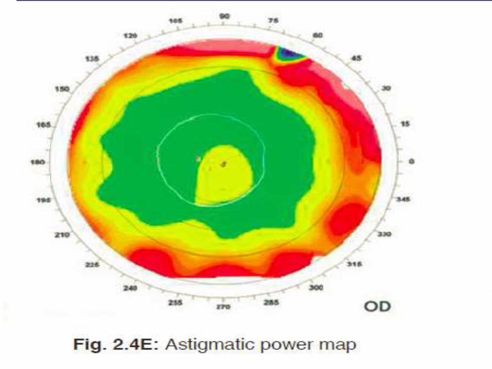
2.REFRACTIVE MAP:
• measures the local corneal D overlying the
pupil .
• useful for identifying central islands in
PRK/LASIK patients.
• The Orbscan II : Axial, Tangential,Optical, Mean
& Astigmatic power maps.
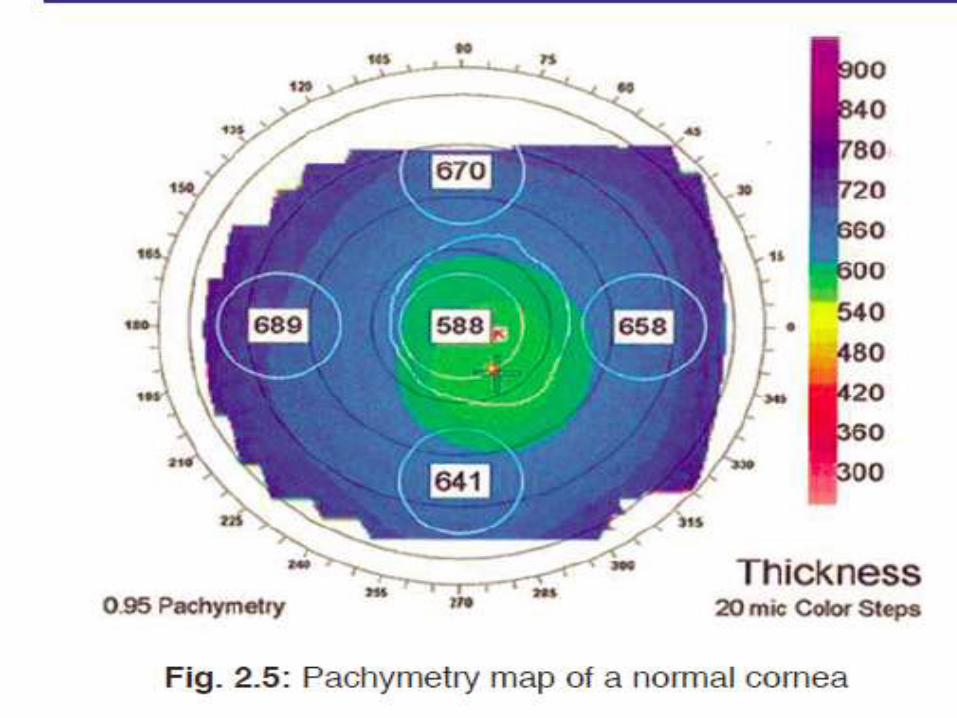
4.pachymetry map
• 30 um ≥ USG pachymetry as value from tear
film endothelium and indentation of tissue by
usg prob.
• Provides thickness across whole cornea .
• Orbscan and usg pachymetry measurements
are not comparable & should not be used
interchangeably
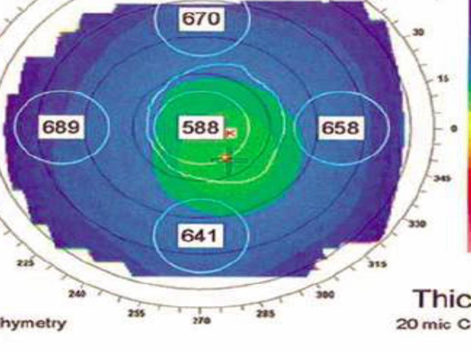
• overlays.
• The circular lines at 3 mm, 5 mm,7 mm,9 mm
areas.
• The pupil centre and outline as well as the k-
lines (steepest and flattest axis of astigmatism)
applied.


PENTACAM• Trade name of comprehensive AS analyser.
• combines a rotating Scheimpflug camera with a static
camera.
• Scheimpflug camera:corneal scan from o to 180°
each of the photographs is an image of the cornea at
a specific angle.
• The static camera :placed in the center to detect the
pupil’s contours and control fixation.
• The light source :UV-free blue LED (475 nm).
• Ultra fast digital signal Processor : utilizes a ray
tracing algorithm to construct and calculate the AS.
• 50 scans in 2 s with 500 true elevation points / scan
surface(25,000 measured ,analyzed true elevation
points.

• available in three models:
• Pentacam BASIC – the individual model
• Pentacam CLASSIC – the versatile model
• Pentacam HR – the professional model
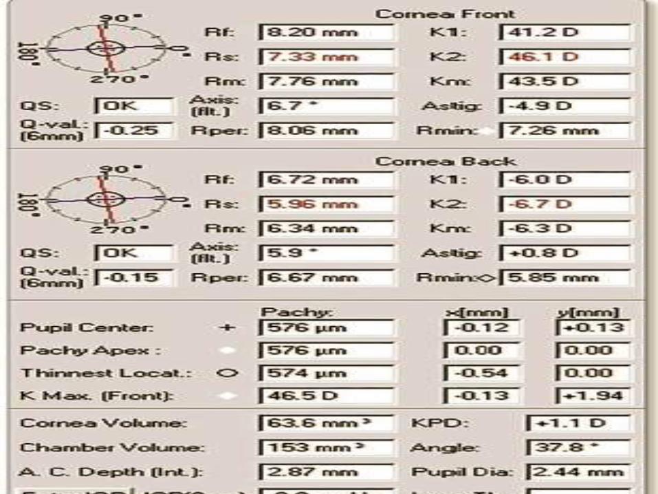
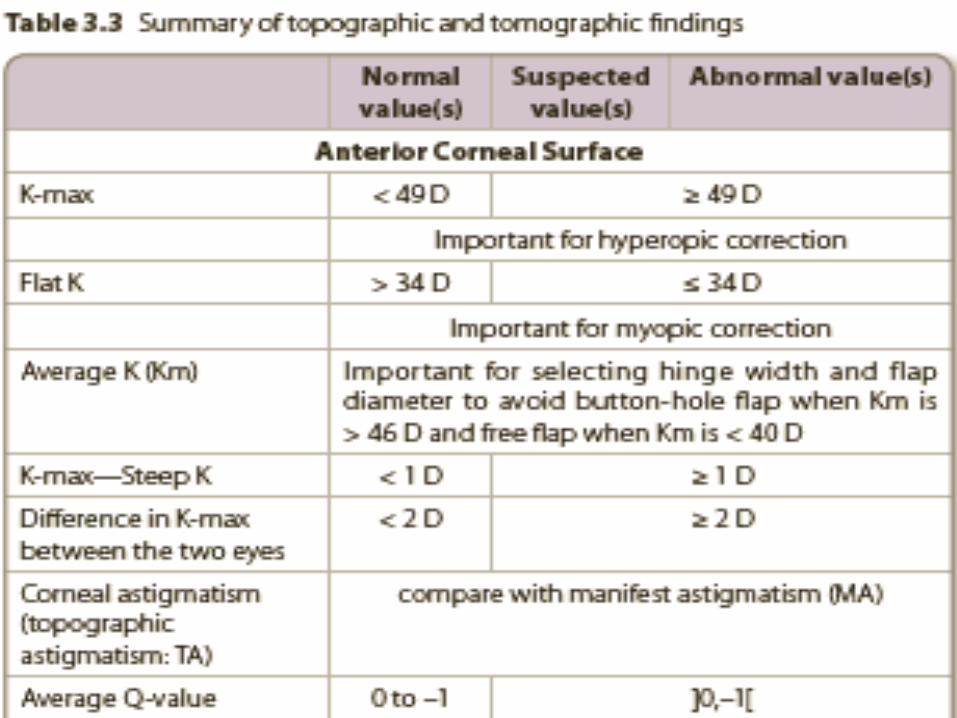
INTERPRETATION OF A PENTACAM MAP
• corneal tomography has two parts:
• corneal parameters on the left side
• 4-view refractive composite map on the right
side.

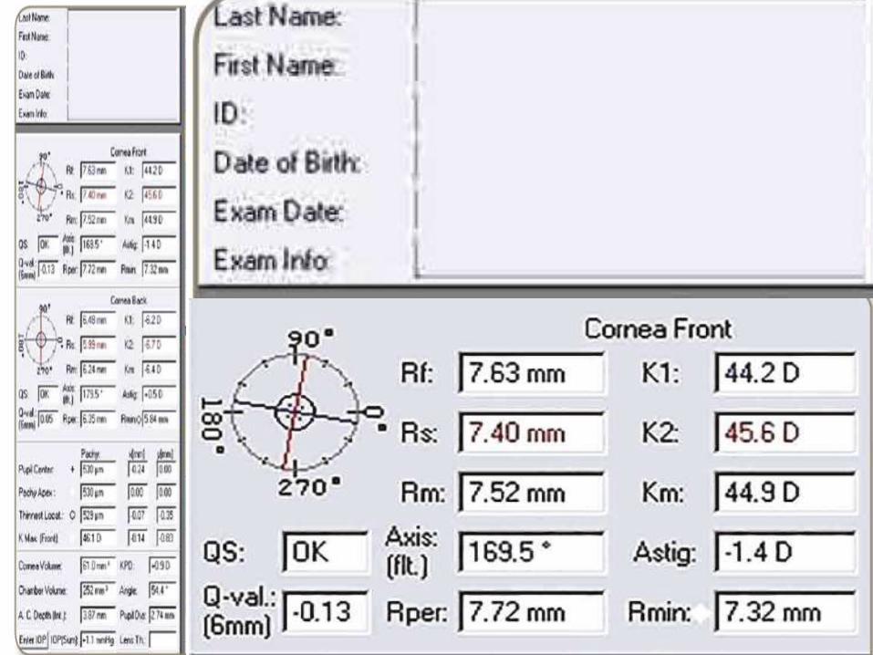
• Qs:
• Quality specification.
• specifies the quality of the tomography.
• “OK”,else computer extrapolates.
• Q-val:
• asphericity of anterior corneal surface.
• The ideal value:measured in 6-mm central zone. In ().
• N/l :–1 to 0.
• Q >0 :oblate corneas(>–3Dphotoablation & RK.
• Q <-1 :hyperprolate corneas(>+3Dphotoablation & KC).
• K1= (Kf)
• power of the flat meridian of the anterior surface of cornea measured within the 3-mm central zone (Sim-K) in diopters (D).
• N/l: > 34 D
• K2=(Ks):
• Curvature power of the steep meridian of the
anterior surface of the cornea measured within
the 3-mm central zone (Sim-K) in D.
• N/l : < 49 D.
• Km=(K-avg):
• Mean curvature power of the anterior surface
of cornea within the 3-mm central zone (Sim-K)
and expressed in D. It should be considered to
avoid flap complications.
• Km < 40 D, free-flap complications
• Km > 46 D ,button-hole complication

• K-max:
• Maximum curvature power of the whole anterior surface of cornea in D.
• N/l Kmax < 49 D,
• Kmax (od) - K-max(os) = < 2 D,
• Kmax (od) - K2(od) = < 1 D.
• If ≥ 1D, K-max instead of K2 used for hyperopic correction to avoid post PRK irregularities.
• Astig:
• Amount of corneal astigmatism on anterior surface
• (K2 – K1) within 3-mm central zone (Sim-K)
• Axis:
• The axis of anterior corneal astigmatism within the 3-mm central zone.

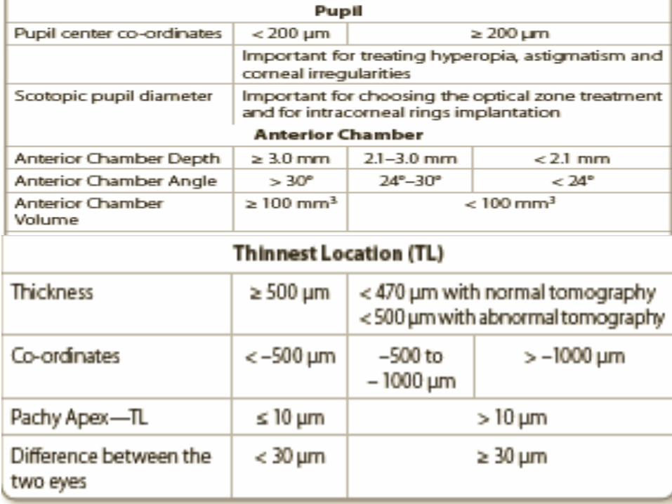
• Pupil center
• for the decentration technique for hyperopia, astigmatism or corneal irregularity treatment.
• to evaluate angle kappa
• Pachy Apex:
• thickness at the apex of the cornea.
• APEX:the origin of the coordinates,
• X and Y are horizontal and vertical meridians
• 0 : both pachy apex coordinates.
• X axis : p/t’s right left(p/t seated opp to physician).
• Y axis :bottom up.
• “+0.2,–0.4” :0.2 mm temporal and 0.4 mm inferior to corneal apex.
• Pupil diameter:
• diameter of pupil in photopic, mesopic or scotopic.
• for adjusting optical zone diameter & ICRS implantation
• Thinnest location (TL):
• thinnest point of the cornea.
• thin cornea <470 μm with n/l OR 500 μm with
Abn/l tomography.
• between both eyes n/l difference:< 30 μm.
• TL - pachy apex ≤ 10 μm.
• minus indicates inferior displacement of the TL.
Anterior Chamber Volume (ACV), Angle
(ACA)Depth (ACD):
• ACV < 100 mm3, ACA < 24° or ACD < 2ACG
• 4 phakic IOL:ACD≥ 3.0 mm,ACA>30°,ACV
≥100 mm3.
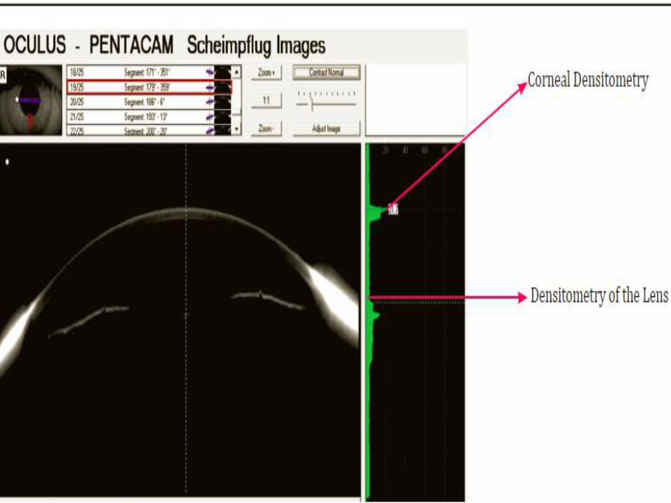
FUNCTION (OUTPUTS1.Scheimpflug image+Densitometry :
• entire anterior segment from cornea posterior
lens surface,
• Densitometry of the lens :
i. The evolution of a cataract can be made visible
even at an early stage
ii. It makes classification of the cataract easy
iii. Long-term controls of cataracts are possible
iv. The extension of the cataract can be measured
• Densitometry of cornea :
Useful 4 evaluation of corneal haze, progression/
regression(post viral keratitis, corneal scars,Post
C3R)
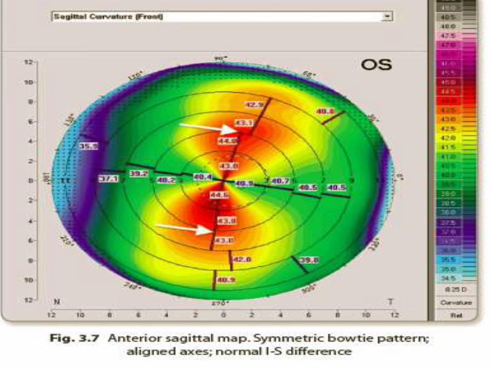
2.Corneal topography map :
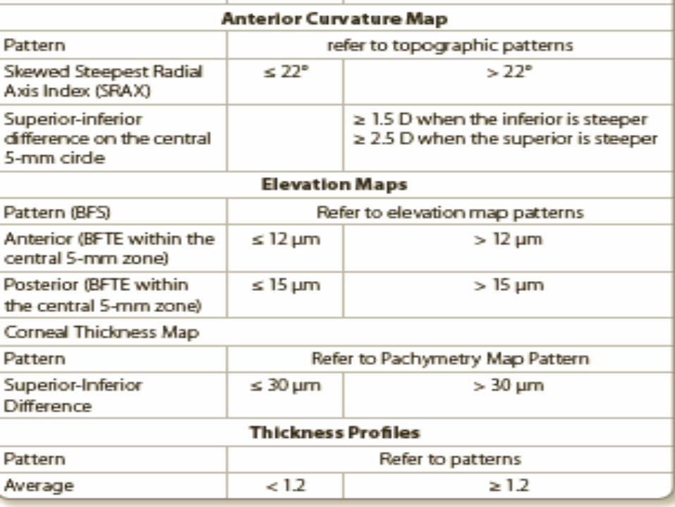
• The Anterior Sagital/tangential Map
• anterior surface dioptric power measured by
sagittal method.
• Steep areas :hot (red,orange),flat areas :cold
(green,blue).
• The cross point of this segmentation :apex
• parameters are studied on the steep axis at the
5-mm central circle.
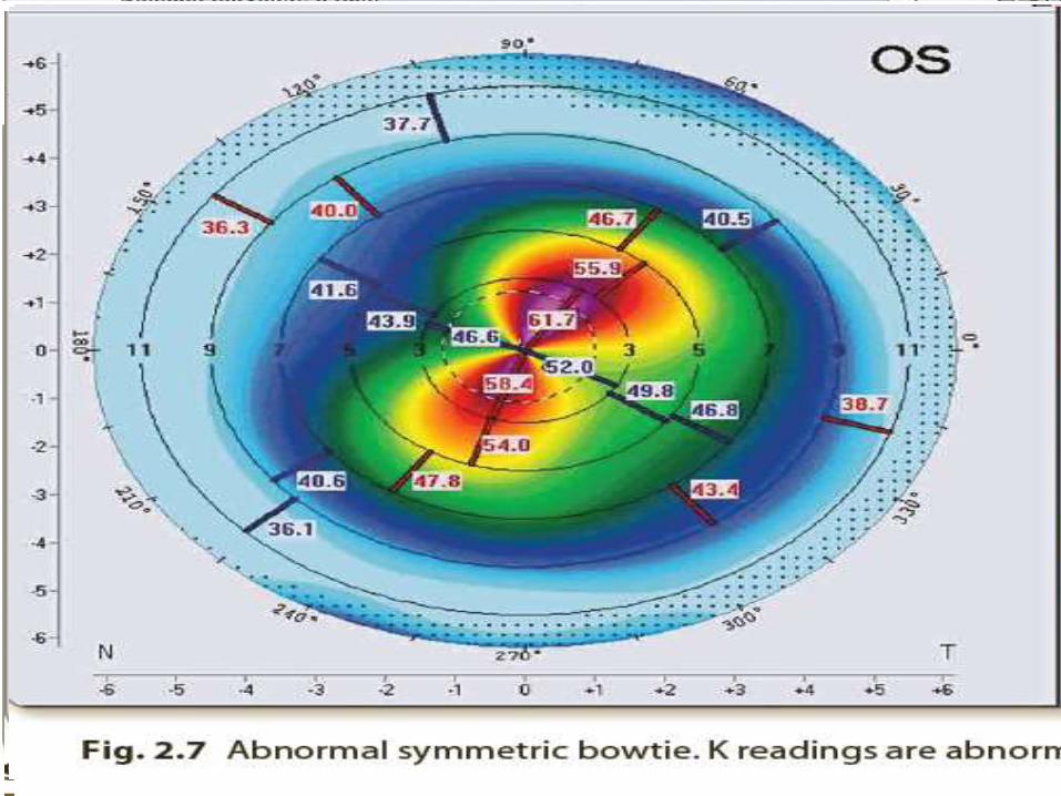
• The n/l pattern :symmetric bowtie (SB)
SB WTR ast. 2 SEGMENTS (A) AND (B) ARE
EQUAL IN SIZE
n/l : I>S, I -S < 1.5 D.
IF S >I ,S-I < 2.5 D
• ABNORMAL PATTERNS
• better seen on the tangential map.
1.Round (R);
2.Oval (O)
3. Superior Steep (SS)
4. Inferior Steep (IS)
5. Irregular (Irr);
6. Abnormal Symmetric Bowtie (SB).
7. Symmetric Bowtie with Skewed Radial Axis (SB/SRAX). The angle
between the axes of the two lobes is >22°
8. Asymmetric Bowtie/Inferior Steep (AB/IS); the I-S >1.5 D,
9. Asymmetric Bowtie/Superior Steep (AB/SS); the S-I >2.5 D;
10. Asymmetric Bowtie with Skewed Radial Axis (AB/SRAX). angle between the axes of the two lobes is >22°
11. Butterfly (B);
12. Claw pattern (C);
13. Junctional (Vertical D);
14. Smiling face (SF);
15. Vortex (V). The steep & flat segments are distributed in a vortex pattern
• The Anterior Tangential Map
• morphologic patterns of the cone in ectatic corneal disorders.(nipple, oval and globus).
• elevation maps
• a and p surfaces of the cornea,
• H8 of cornea vs BFS.
• 4 refractive sx screening, the ideal diameter of RS is 8 mm and mode is the float mode.
• Shape : n/l: symmetric hourglass
• Abnormal shapes :
a. Skewed hourglass :large angle Kappa and misalignment during taking the capture,abn/l distorted cornea.
b. Tongue-like extension and irregular hourglass :abn/l distorted corneas.
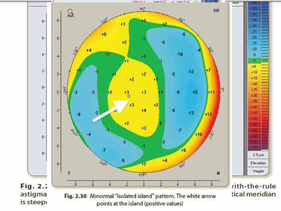
c. Isolated island :abnormal distorted corneas with central/ paracentral protrusion.
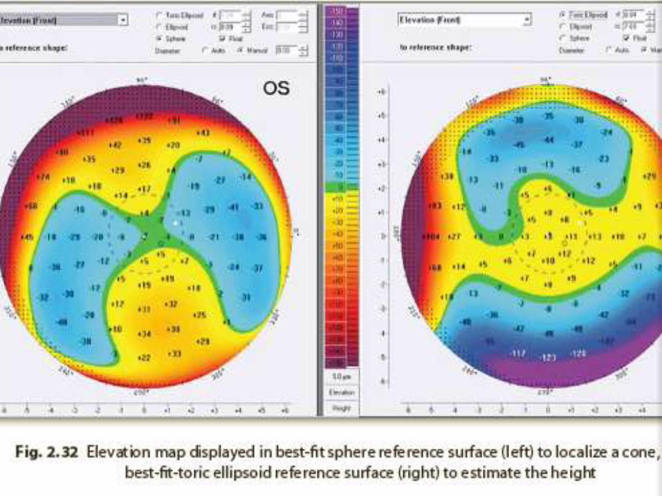
• Parameters (BFTE float mode): Look at the
highest plus values within central 5-mm zone
• Abnormal > 12 μm and > 15 μm on the a and p
elevation maps respectively.
• Cone can be quantified in ectatic corneal d/s
• Parameters (BFS float mode): Another
method of quantification done by pointing with
the cursor at the TL symbol on the elevation
maps and left click on the mouse to display the
values.
• cone can be localized In ectatic corneal d/s.
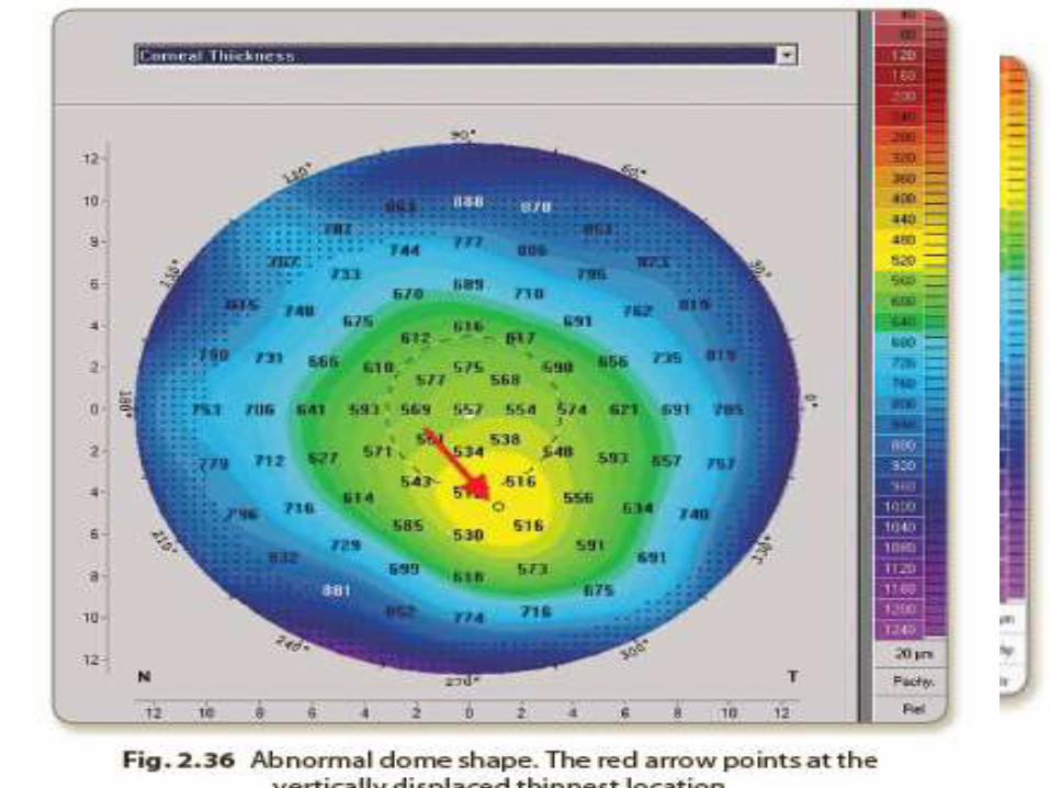
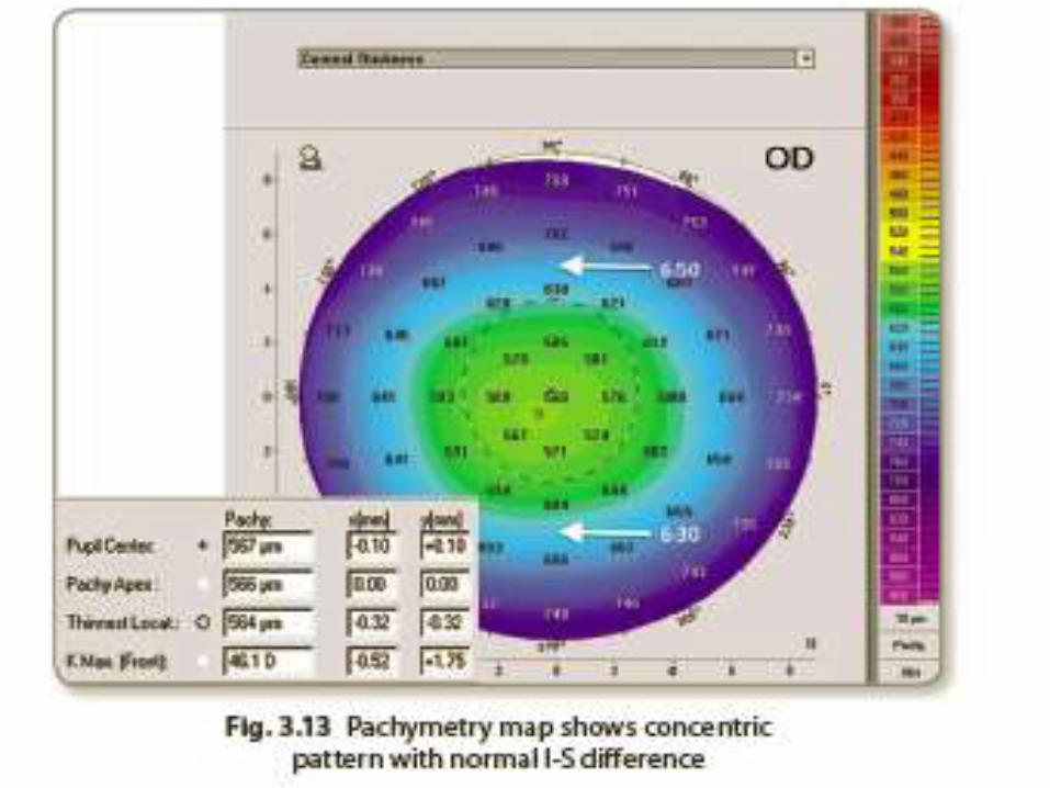
3.The Pachymetry Map
• The corneal thickness is displayed as a colour image over its entire area from limbus to limbus.
• 3 main landmarks
– cornea apex (orange arrow),
– TL (red arrow),
– 2 opposing points on the vertical meridian at the central 5-mm circle(white dotted arrows)
• S- I ≤ 30 μm n/l.
• Shape: normal:concentric shape
• Abnormal shapes include:
a. Horizontal displacement of the TL .
b. Dome shape. The TL is vertically displaced .
c. Bell shape. There is a thin band in the inferior part of the cornea(PMD).
d. Keratoglobus. A generalized thinning reaching the limbus
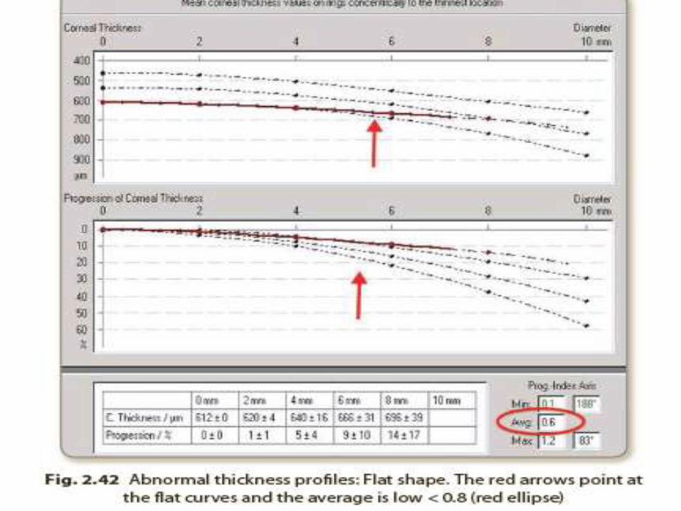
• 2 pachymetry profiles:
• corneal thickness spatial profile (CTSP)
average progression of thickness starting from the TL to corneal periphery in relation to zones concentric with the TL
• percentage thickness increase (PTI).
• the percentage of progression of the same
• The normal profile is a curved line plotted in red, parallel to the course of the normative black dotted curves,
• Abnormal profiles include:
a. Quick Slope . The red curve leaves its course before
the 6-mm zone. forme fruste keratoconus
b. S-shape :The red curve has a shape of an “S”. FFKC and ectatic disorders.
c. Flat shape :The red curve takes a straight course. oedematous corneas
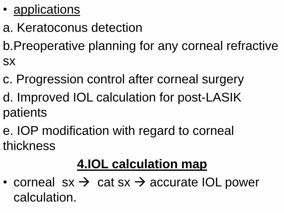
• applications
a. Keratoconus detection
b.Preoperative planning for any corneal refractive
sx
c. Progression control after corneal surgery
d. Improved IOL calculation for post-LASIK
patients
e. IOP modification with regard to corneal
thickness
4.IOL calculation map
• corneal sx cat sx accurate IOL power
calculation.
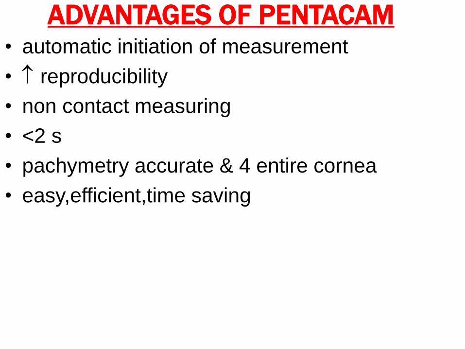
ADVANTAGES OF PENTACAM• automatic initiation of measurement
• reproducibility
• non contact measuring
• <2 s
• pachymetry accurate & 4 entire cornea
• easy,efficient,time saving
• STEPS OF READING CORNEAL
TOMOGRAPHY
1. Display the 4-view refractive composite map
and take an overview to scan for any irregular
shapes.
2. Study the corneal parameters and focus on the
parameters of anterior corneal surface, corneal
thickness and anterior chamber. Mention all the
parameters in your report
3. Study each map separately:
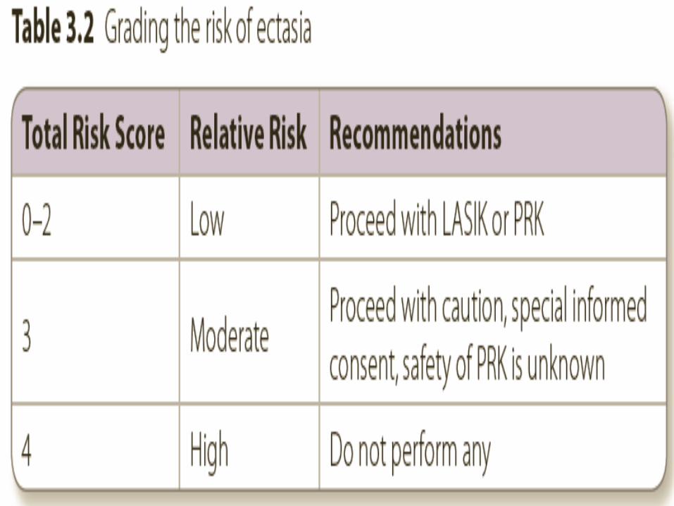
4. Scoring the Case
-accumulative score
-the risk of developing iatrogenic ectasia
after
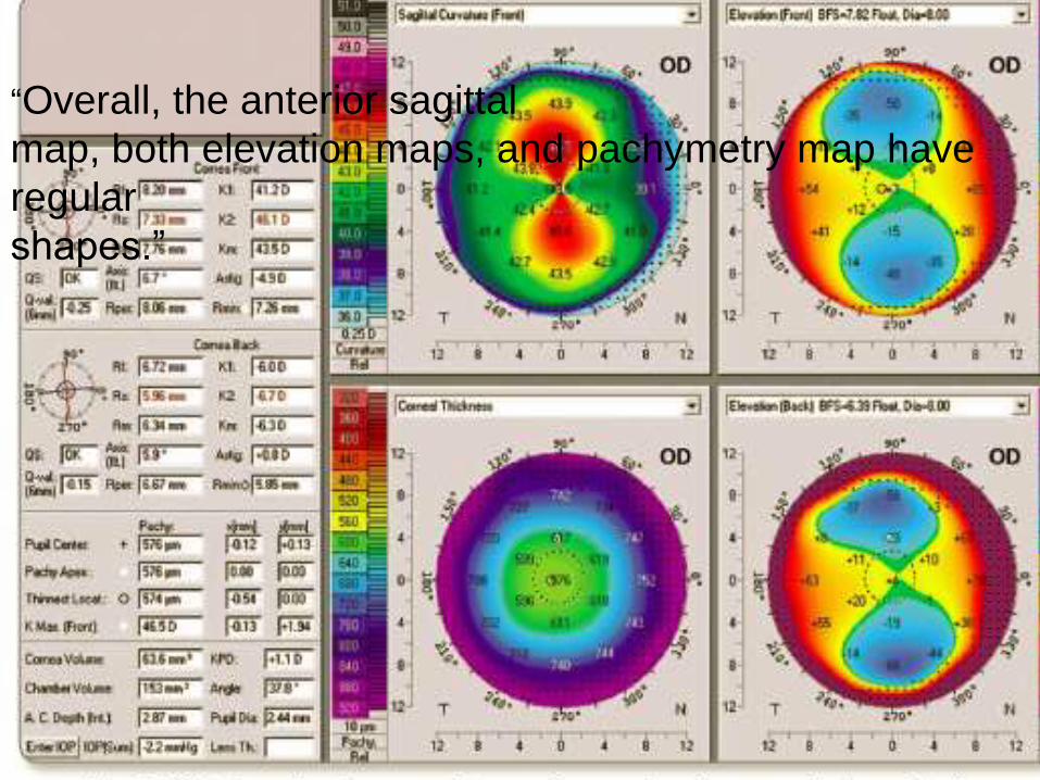
“Overall, the anterior sagittal
map, both elevation maps, and pachymetry map have
regular
shapes.”
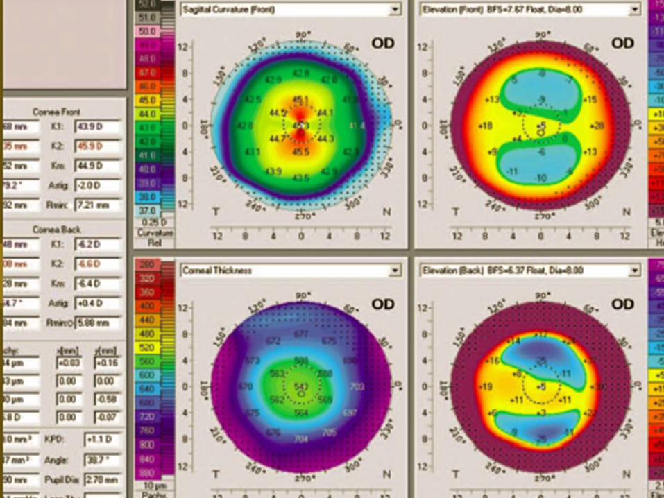
• Overall, the elevation maps show some
irregularities more obvious on the posterior
one.Other maps look regular.
• “Quality of the image (QS) is OK for both
surfaces. K-readings are within the normal
range; both K2 and K-max are < 49 D and (K-
max—K2) is < 1 D. The amount and axis of TA
should be compared with MA. Q-value of both
surfaces is within the normal range [–1 , 0]. TL
is > 500 μm. Difference in thickness between
the TL and pachy apex is < 10 μm. There is no
vertical displacement of the TL. Angle kappa is
not significant; x-coordinate is < 200 μm in
absolute value. ACV is > 100 mm3, ACA is
normal and > 30°, ACD is normal (> 2.1 mm)
but < 3.0 mm.
• “The anterior sagittal map:SB, no SRAX, I-S = 1
D, which is normal.”

“The posterior
elevation map shows tongue-like extension in BFS mode
and
abnormal values (> 15 μm) within the central 5-mm zone in
BFTE mode.”
• The pachymetry map:concentric pattern, I-S
is normal (< 30 μm), and there is no
horizontal or vertical displacement in the TL.”
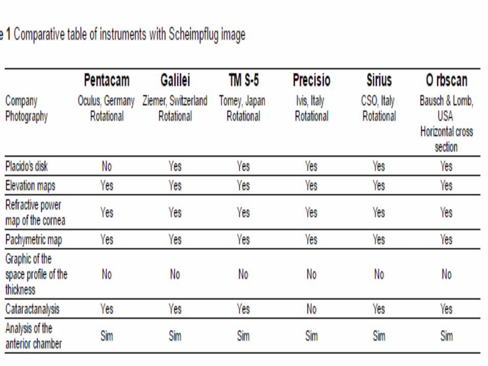
• GALILEI DUAL SCHEIMPFLUG ANALYZER
• integrates a Placido disc and a dual rotating Scheimpflug system for corneal topography 4 3D analysis of the AS.
• covers the cornea, anterior chamber and lens .
• Placido disc and Scheimpflug images are simultaneously acquired to obtain the information on the curvature and elevation of the cornea respectively.
• The Pentacam and Galilei are interchangeable contrary to Sirius
SIRIUS SCHEIMPFLUG ANALYZER • integrates a Placido disc and a mono rotating
Scheimpflug system for corneal topography 4 3D analysis of AS.
• elevation maps are displayed in Sirius in a special