Embed Size (px)
Citation preview

INTRODUCTION TO PIPELINING
Review of Last Class
MIPS Instruction Set Architecture Overview of IA32
What is Multiprocessing
Parallelism at the Instruction Level is limited because of data dependency => Speed up is limited!!
Abundant availability of program level parallelism, like Do I = 1000, Loop Level Parallelism. How about employing multiple processors to execute the loops => Parallel processing or Multiprocessing
With billion transistors on a chip, we can put a few CPUs in one chip => Chip multiprocessor
Memory Latency Problem
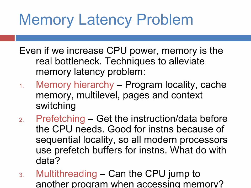
Even if we increase CPU power, memory is the real bottleneck. Techniques to alleviate memory latency problem:
1. Memory hierarchy – Program locality, cache memory, multilevel, pages and context switching
2. Prefetching – Get the instruction/data before the CPU needs. Good for instns because of sequential locality, so all modern processors use prefetch buffers for instns. What do with data?
3. Multithreading – Can the CPU jump to another program when accessing memory? It’s like multiprogramming!!
Hardware Multithreading
We need to develop a hardware multithreading technique because switching between threads in software is very time-consuming (Why?), so not suitable for main memory (instead of I/O) access, Ex: Multitasking
Develop multiple PCs and register sets on the CPU so that thread switching can occur without having to store the register contents in main memory (stack, like it is done for context switching).
Several threads reside in the CPU simultaneously, and execution switches between the threads on main memory access.
How about both multiprocessors and multithreading on a chip? => Network Processor
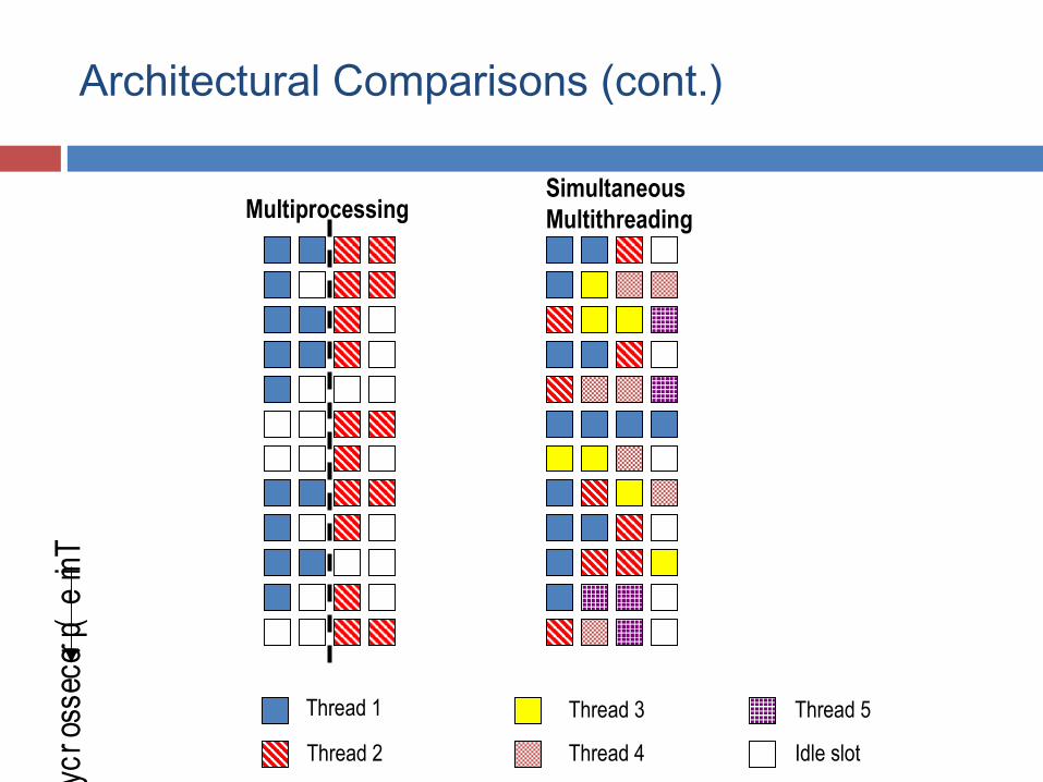
Architectural Comparisons (cont.)Tim
e (processor cycle)
Multiprocessing
Thread 1
Thread 2
Thread 3
Thread 4
Thread 5
Idle slot
SimultaneousMultithreading
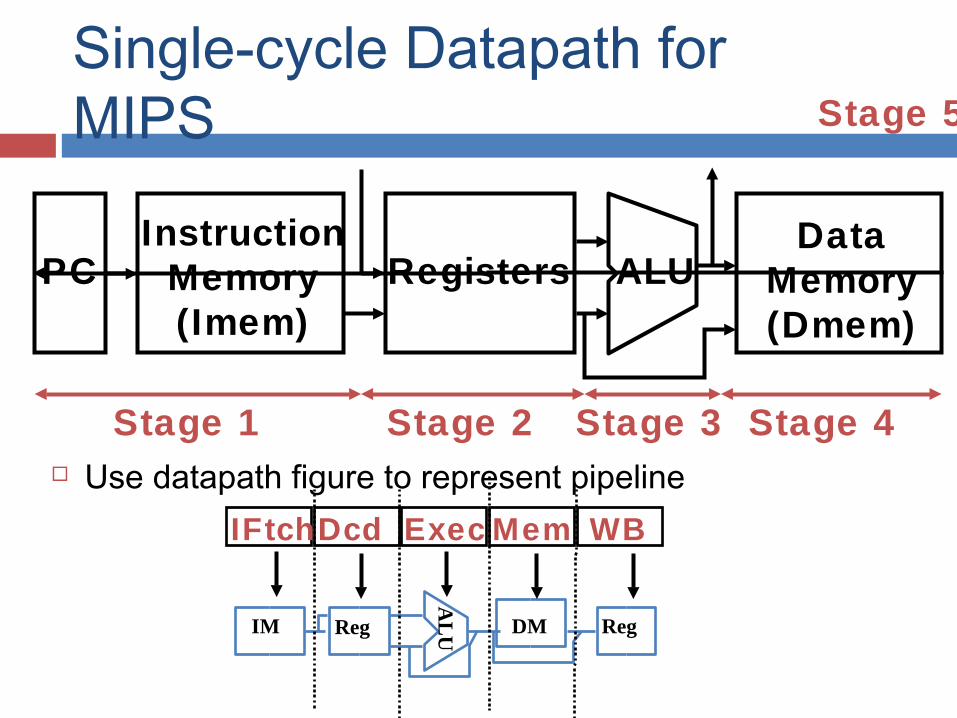
Single-cycle Datapath for MIPS
Use datapath figure to represent pipeline
DataMemory(Dmem)
PC Registers ALUInstruction
Memory(Imem)
Stage 1 Stage 2 Stage 3 Stage 4
Stage 5
IFtchDcd Exec Mem WBA
LU IM Reg DM Reg
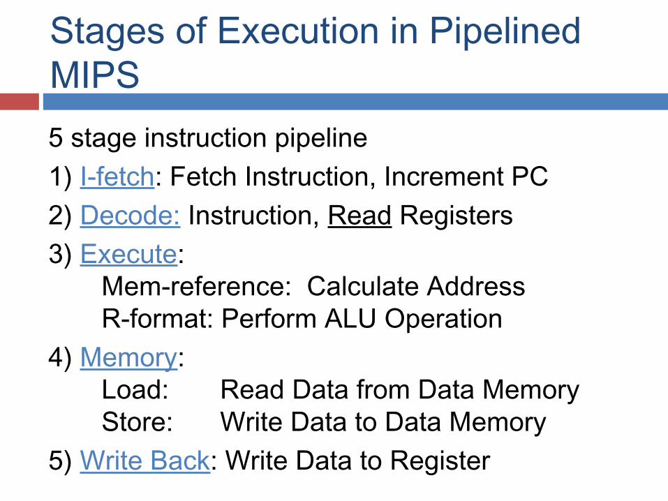
Stages of Execution in Pipelined MIPS5 stage instruction pipeline 1) I-fetch: Fetch Instruction, Increment PC2) Decode: Instruction, Read Registers3) Execute:
Mem-reference: Calculate Address R-format: Perform ALU Operation
4) Memory: Load: Read Data from Data Memory Store: Write Data to Data Memory
5) Write Back: Write Data to Register
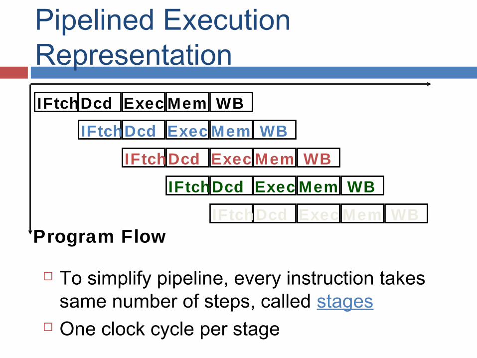
Pipelined Execution Representation
To simplify pipeline, every instruction takes same number of steps, called stages
One clock cycle per stage
IFtchDcd Exec Mem WB
IFtchDcd Exec Mem WB
IFtchDcd Exec Mem WB
IFtchDcd Exec Mem WB
IFtchDcd Exec Mem WBProgram Flow
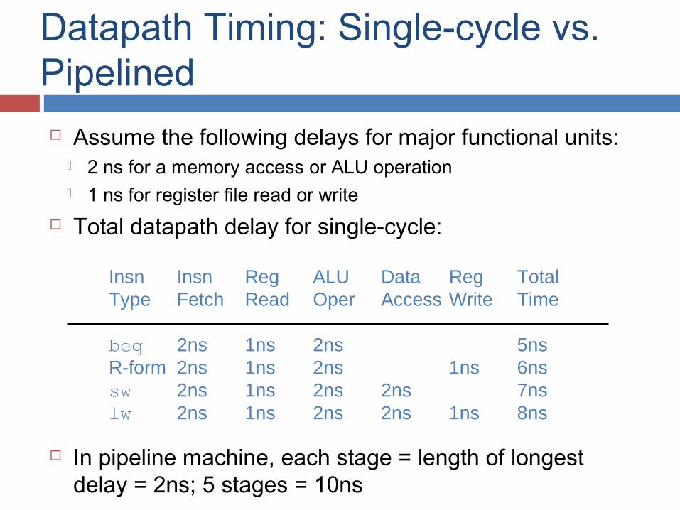
Datapath Timing: Single-cycle vs. Pipelined Assume the following delays for major functional units:
2 ns for a memory access or ALU operation 1 ns for register file read or write
Total datapath delay for single-cycle:
In pipeline machine, each stage = length of longest delay = 2ns; 5 stages = 10ns
Insn Insn Reg ALU Data Reg TotalType Fetch Read Oper Access Write Time
beq 2ns 1ns 2ns 5nsR-form 2ns 1ns 2ns 1ns 6nssw 2ns 1ns 2ns 2ns 7nslw 2ns 1ns 2ns 2ns 1ns 8ns
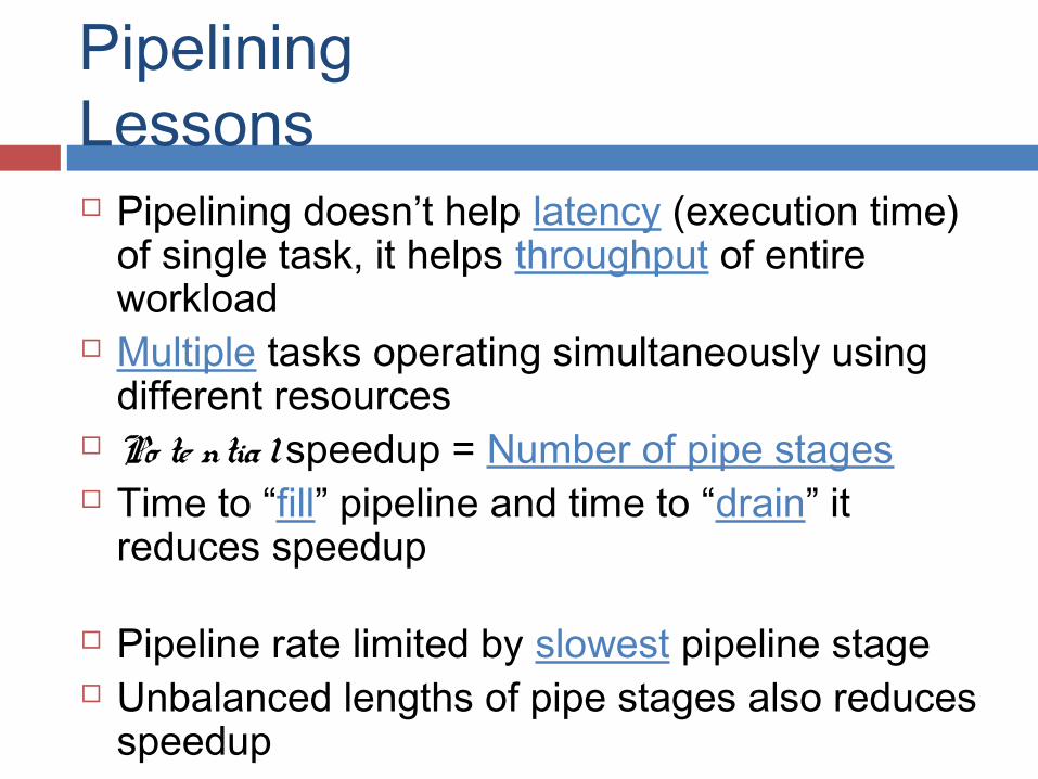
Pipelining Lessons Pipelining doesn’t help latency (execution time)
of single task, it helps throughput of entire workload
Multiple tasks operating simultaneously using different resources
Po te ntia l speedup = Number of pipe stages Time to “fill” pipeline and time to “drain” it
reduces speedup
Pipeline rate limited by slowest pipeline stage Unbalanced lengths of pipe stages also reduces
speedup
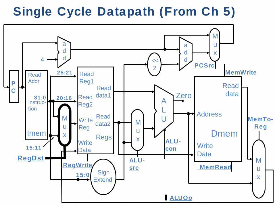
Single Cycle Datapath (From Ch 5)
Regs
ReadReg1
Readdata1
ALURead
data2
ReadReg2
WriteReg
WriteData
Zero
ALU-con
RegWrite
Address
Readdata
WriteData
SignExtend
Dmem
MemRead
MemWrite
Mux
MemTo-Reg
Mux
Read Addr
Instruc-tion
Imem
4
PC
add
add <<
2
Mux
PCSrc
ALUOp
ALU-src
Mux
25:21
20:16
15:11
RegDst
15:0
31:0
Required Changes to Datapath Introduce registers to separate 5 stages by
putting IF/ID, ID/EX, EX/MEM, and MEM/WB registers in the datapath.
Next PC value is computed in the 3rd step, but we need to bring in next instn in the next cycle – Move PCSrc Mux to 1st stage. The PC is incremented unless there is a new branch address.
Branch address is computed in 3rd stage. With pipeline, the PC value has changed! Must carry the PC value along with instn. Width of IF/ID register = (IR)+(PC) = 64 bits.
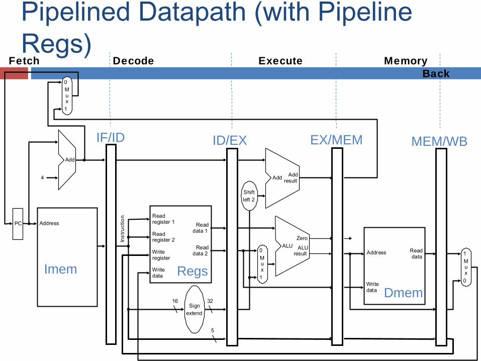
Pipelined Datapath (with Pipeline Regs)
Address
4
32
0
Add Addresult
Shiftleft 2
Ins
tru
ctio
n
Mux
0
1
Add
PC
0
Address
Writedata
Mux
1
Readdata 1
Readdata 2
Readregister 1
Readregister 2
16Sign
extend
Writeregister
Writedata
Readdata
1
ALUresult
Mux
ALU
Zero
Imem
Dmem
Regs
IF/ID ID/EX EX/MEM MEM/WB
5
Fetch Decode Execute Memory Write Back
Homework
Assignment: What are the lengths of IF/ID ID/EX EX/MEM and MEM/WB registers?
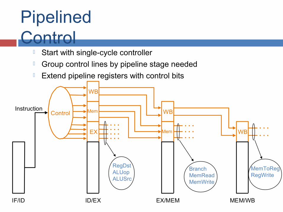
Pipelined Control
Start with single-cycle controller Group control lines by pipeline stage needed Extend pipeline registers with control bits
Control
EX
Mem
WB
WB
WB
IF/ID ID/EX EX/MEM MEM/WB
Instruction
Mem
RegDstALUopALUSrc
BranchMemReadMemWrite
MemToRegRegWrite
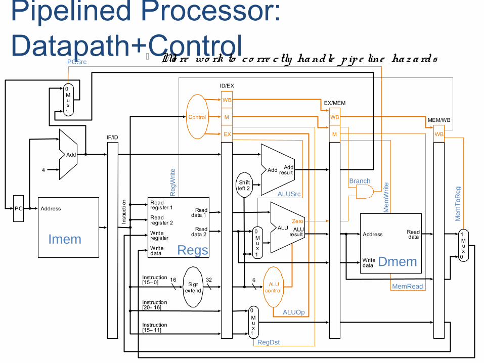
Pipelined Processor: Datapath+Control Mo re wo rk to c o rre c tly ha ndle p ip e line ha z a rds
PC
Inst
ruct
ion
Add
Instruction[20– 16]
4
16 32Instruction[15– 0]
0
0
Mux
0
1
Add Addresul t
Writeregis ter
Writedata
Readdata 1
Readdata 2
Readregis ter 1
Readregis ter 2
Signextend
Mux1
ALUresult
Zero
Writedata
Readdata
Mux
1
ALUcontrol
Sh iftleft 2
Control
ALU
Instruction[15– 11]
6
EX
M
WB
M
WB
WBIF/ID
ID/EX
EX/MEM
MEM/WB
Mux
0
1
Address
Address
Reg
Writ
e
ALUSrc
ALUOp
RegDst
MemRead
Mem
ToR
eg
Mem
Writ
eBranch
PCSrc
Imem
DmemRegs
In short
if can keep all pipeline stages busy, can retire (complete) up to one instruction per clock cycle (thereby achieving single-cycle thro ug hp ut)
The pipeline paradox (for MIPS): any instruction still takes 5 cycles to execute (even though can retire one instruction per cycle)
Problems for Pipelining Hazards prevent next instruction from
executing during its designated clock cycle, limiting speedup Structural hazards: HW cannot support this
combination of instructions (single memory for instruction and data)
Data hazards: Instruction depends on result of prior instruction still in the pipeline
Control hazards: conditional branches & other instructions may stall the pipeline delaying later instructions
M
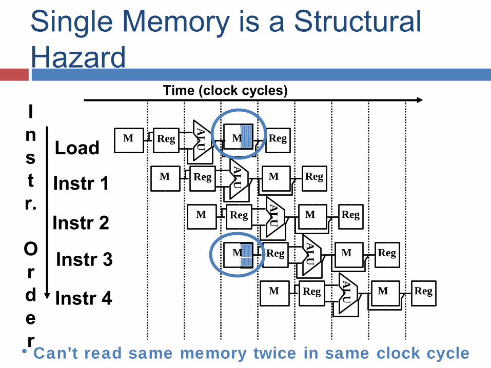
Single Memory is a Structural Hazard
Load
Instr 1
Instr 2
Instr 3
Instr 4A
LU M Reg M Reg
AL
U M Reg M Reg
AL
U M Reg M Reg
AL
UReg M Reg
AL
U M Reg M Reg
• Can’t read same memory twice in same clock cycle
Instr.
Order
Time (clock cycles)
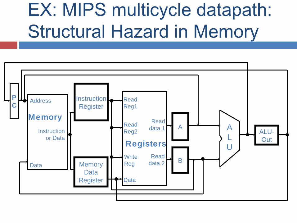
EX: MIPS multicycle datapath: Structural Hazard in Memory
Registers
ReadReg1
ALU
ReadReg2
WriteReg
Data
PC
Address
Instructionor Data
MemoryA
B
ALU-Out
InstructionRegister
Data MemoryData
Register
Readdata 1
Readdata 2
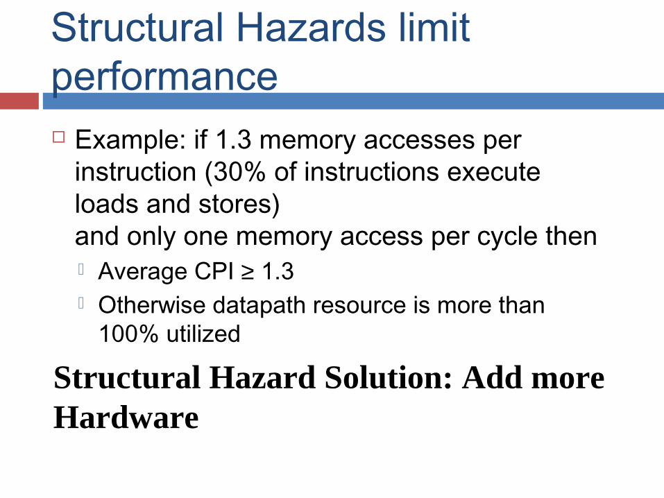
Structural Hazards limit performance Example: if 1.3 memory accesses per
instruction (30% of instructions execute loads and stores)and only one memory access per cycle then Average CPI ≥ 1.3 Otherwise datapath resource is more than
100% utilized
Structural Hazard Solution: Add more Hardware
Speed Up Equation for Pipelining
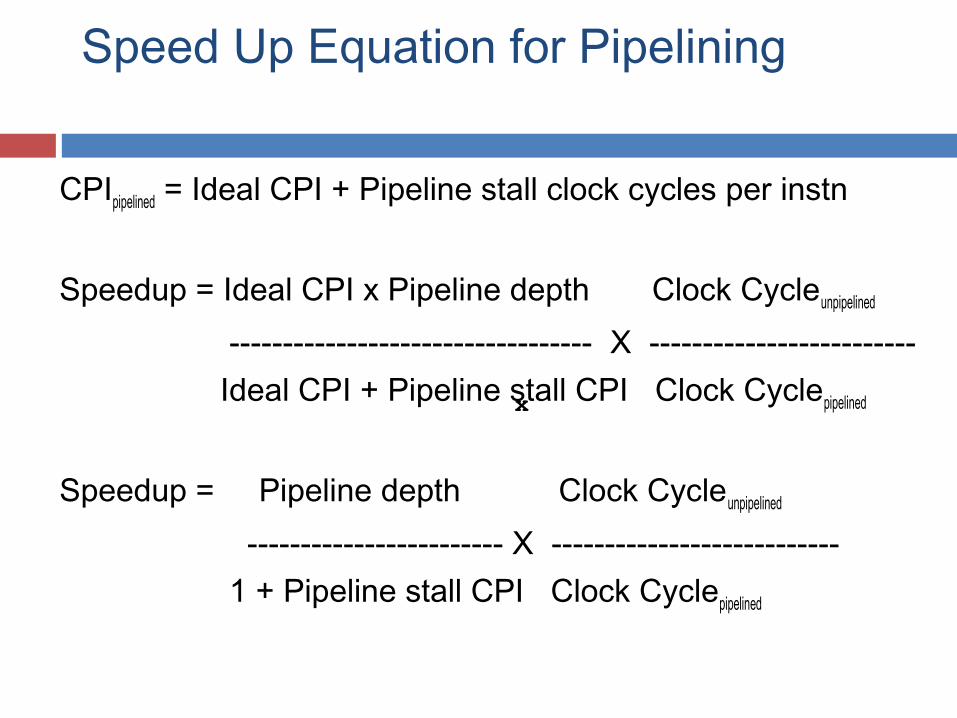
CPIpipelined = Ideal CPI + Pipeline stall clock cycles per instn
Speedup = Ideal CPI x Pipeline depth Clock Cycleunpipelined
---------------------------------- X ------------------------- Ideal CPI + Pipeline stall CPI Clock Cyclepipelined
Speedup = Pipeline depth Clock Cycleunpipelined
------------------------ X --------------------------- 1 + Pipeline stall CPI Clock Cyclepipelined
x
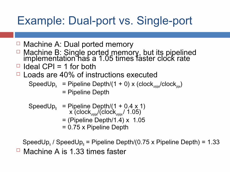
Example: Dual-port vs. Single-port
Machine A: Dual ported memory Machine B: Single ported memory, but its pipelined
implementation has a 1.05 times faster clock rate Ideal CPI = 1 for both Loads are 40% of instructions executed SpeedUpA = Pipeline Depth/(1 + 0) x (clockunpipe/clockpipe) = Pipeline Depth
SpeedUpB = Pipeline Depth/(1 + 0.4 x 1) x (clockunpipe/(clockunpipe / 1.05)
= (Pipeline Depth/1.4) x 1.05 = 0.75 x Pipeline Depth
SpeedUpA / SpeedUpB = Pipeline Depth/(0.75 x Pipeline Depth) = 1.33 Machine A is 1.33 times faster
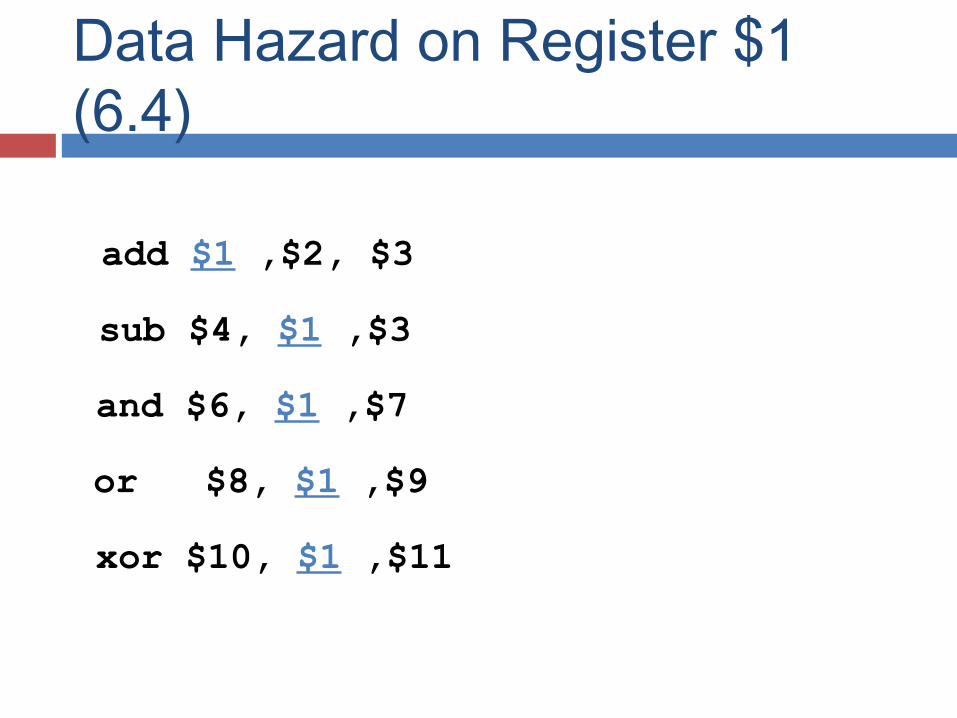
Data Hazard on Register $1 (6.4)
add $1 ,$2, $3
sub $4, $1 ,$3
and $6, $1 ,$7
or $8, $1 ,$9
xor $10, $1 ,$11
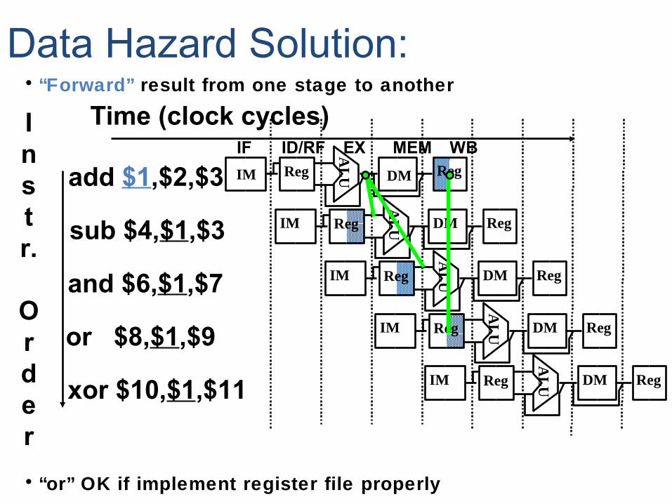
• “Forward” result from one stage to another
• “or” OK if implement register file properly
Data Hazard Solution:
add $1,$2,$3
sub $4,$1,$3
and $6,$1,$7
or $8,$1,$9
xor $10,$1,$11
IF ID/RF EX MEM WBAL
UIM Reg DM Reg
AL
UIM Reg DM RegA
LUIM Reg DM Reg
IM
AL
UReg DM Reg
AL
UIM Reg DM Reg
Instr.
Order
Time (clock cycles)
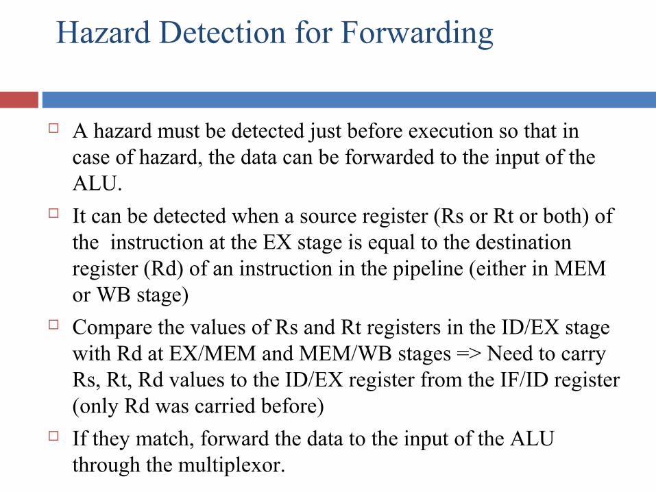
Hazard Detection for Forwarding
A hazard must be detected just before execution so that in case of hazard, the data can be forwarded to the input of the ALU.
It can be detected when a source register (Rs or Rt or both) of the instruction at the EX stage is equal to the destination register (Rd) of an instruction in the pipeline (either in MEM or WB stage)
Compare the values of Rs and Rt registers in the ID/EX stage with Rd at EX/MEM and MEM/WB stages => Need to carry Rs, Rt, Rd values to the ID/EX register from the IF/ID register (only Rd was carried before)
If they match, forward the data to the input of the ALU through the multiplexor.
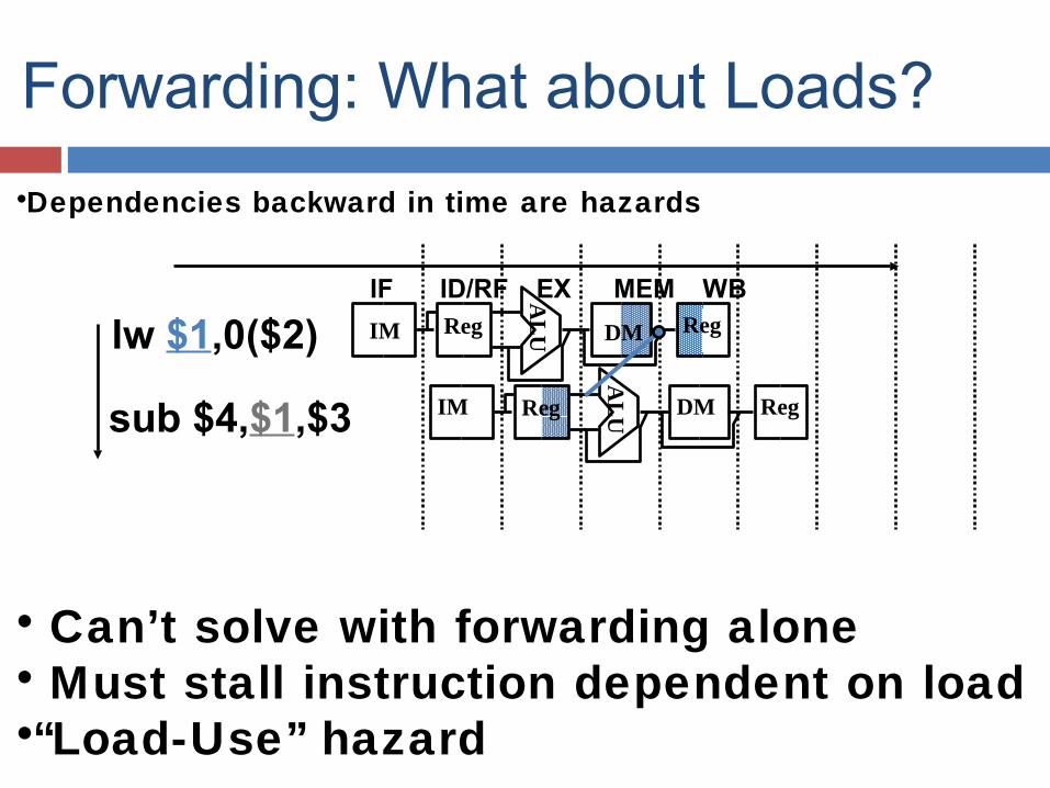
•Dependencies backward in time are hazards
• Can’t solve with forwarding alone• Must stall instruction dependent on load•“Load-Use” hazard
Forwarding: What about Loads?
lw $1,0($2)
sub $4,$1,$3
IF ID/RF EX MEM WBAL
UIM Reg DM Reg
AL
UIM Reg DM Reg
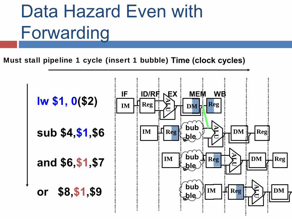
• Must stall pipeline 1 cycle (insert 1 bubble)
lw $1, 0($2)
sub $4,$1,$6
and $6,$1,$7
or $8,$1,$9
IF ID/RF EX MEM WBAL
UIM Reg DM Reg
AL
UIM Reg DM Reg
AL
UIM Reg DM Reg
IM
AL
UReg DM
Time (clock cycles)
bubble
bubble
bubble
Data Hazard Even with Forwarding
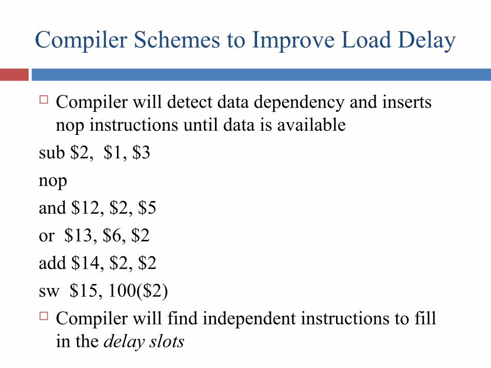
Compiler Schemes to Improve Load Delay
Compiler will detect data dependency and inserts nop instructions until data is available
sub $2, $1, $3
nop
and $12, $2, $5
or $13, $6, $2
add $14, $2, $2
sw $15, 100($2) Compiler will find independent instructions to fill
in the delay slots
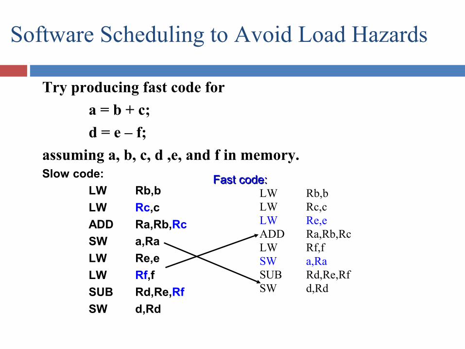
Try producing fast code for
a = b + c;
d = e – f;
assuming a, b, c, d ,e, and f in memory. Slow code:
LW Rb,b
LW Rc,c
ADD Ra,Rb,Rc
SW a,Ra
LW Re,e
LW Rf,f
SUB Rd,Re,Rf
SW d,Rd
Software Scheduling to Avoid Load Hazards
Fast code:Fast code:LW Rb,bLW Rc,cLW Re,e ADD Ra,Rb,RcLW Rf,fSW a,Ra SUB Rd,Re,RfSW d,Rd