Embed Size (px)
Citation preview
CPE 408441Computer Architecture
Fall2009
Appendix A: Pipelining: Basic and Intermediate Concepts
Sa’ed R. Abed[Computer Engineering Department,
Hashemite University]
2
Outline
Basic concept of Pipelining
The Basic Pipeline for MIPS
The Major Hurdles of Pipelining – Pipeline Hazards
CPE 0408441 @2009 S. Abed - HU, Jordan
3
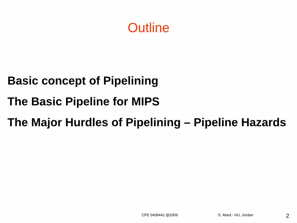
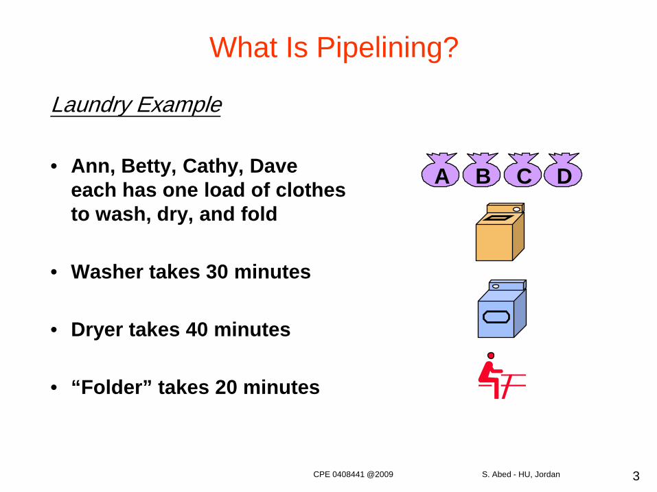
What Is Pipelining?
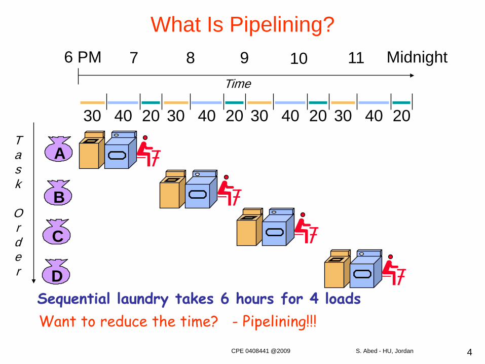
Laundry Example
• Ann, Betty, Cathy, Dave each has one load of clothes to wash, dry, and fold
• Washer takes 30 minutes
• Dryer takes 40 minutes
• “Folder” takes 20 minutes
A B C D
CPE 0408441 @2009 S. Abed - HU, Jordan
4
What Is Pipelining?
Sequential laundry takes 6 hours for 4 loads
A
B
C
D
30 40 20 30 40 20 30 40 20 30 40 20
6 PM 7 8 9 10 11 Midnight
Task
Order
Time
Want to reduce the time? - Pipelining!!!
CPE 0408441 @2009 S. Abed - HU, Jordan
5
What Is Pipelining?
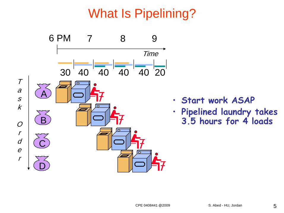
• Start work ASAP• Pipelined laundry takes
3.5 hours for 4 loads
A
B
C
D
Task
Order
6 PM 7 8 9Time
30 40 40 40 40 20
CPE 0408441 @2009 S. Abed - HU, Jordan
6
• Pipelining doesn’t help latency of single task; it helps throughput of entire workload
• Pipeline rate is limited by the slowest pipeline stage• Multiple tasks operating simultaneously• Potential speedup = Number of pipe stages
– Unbalanced lengths of pipe stages reduces speedup
What Is Pipelining?
Pipelining is an implementation technique whereby multiple instructions are overlapped in execution
It takes advantage of parallelism that exists among instructions => instruction-level parallelism
It is the key implementation technique used to make fast CPUs
CPE 0408441 @2009 S. Abed - HU, Jordan
7
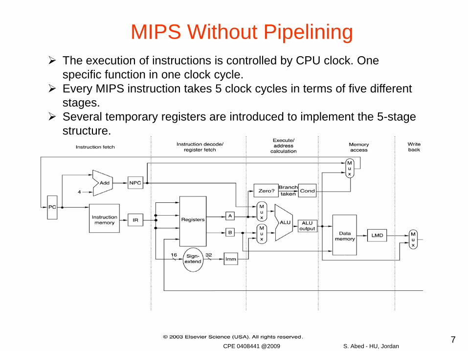
MIPS Without Pipelining The execution of instructions is controlled by CPU clock. One
specific function in one clock cycle. Every MIPS instruction takes 5 clock cycles in terms of five different
stages. Several temporary registers are introduced to implement the 5-stage
structure.
CPE 0408441 @2009 S. Abed - HU, Jordan
8
MIPS Functions
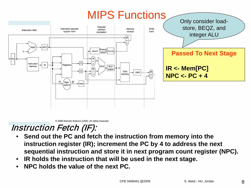
Instruction Fetch (IF):• Send out the PC and fetch the instruction from memory into the
instruction register (IR); increment the PC by 4 to address the next sequential instruction and store it in next program count register (NPC).
• IR holds the instruction that will be used in the next stage.• NPC holds the value of the next PC.
Passed To Next Stage
IR <- Mem[PC]NPC <- PC + 4
Only consider load-store, BEQZ, and
integer ALU
CPE 0408441 @2009 S. Abed - HU, Jordan
9
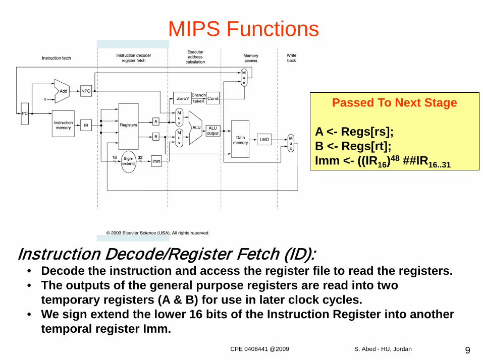
Instruction Decode/Register Fetch (ID):• Decode the instruction and access the register file to read the registers.• The outputs of the general purpose registers are read into two
temporary registers (A & B) for use in later clock cycles.• We sign extend the lower 16 bits of the Instruction Register into another
temporal register Imm.
Passed To Next Stage
A <- Regs[rs];B <- Regs[rt];Imm <- ((IR16)48 ##IR16..31
MIPS Functions
CPE 0408441 @2009 S. Abed - HU, Jordan
10
Passed To Next Stage
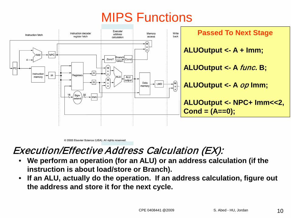
ALUOutput <- A + Imm;
ALUOutput <- A func. B;
ALUOutput <- A op Imm;
ALUOutput <- NPC+ Imm<<2,Cond = (A==0);
Execution/Effective Address Calculation (EX):• We perform an operation (for an ALU) or an address calculation (if the
instruction is about load/store or Branch).• If an ALU, actually do the operation. If an address calculation, figure out
the address and store it for the next cycle.
MIPS Functions
CPE 0408441 @2009 S. Abed - HU, Jordan
11
Passed To Next Stage
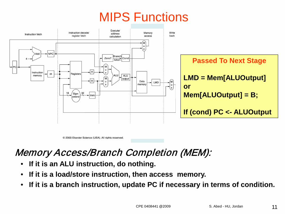
LMD = Mem[ALUOutput]orMem[ALUOutput] = B;
If (cond) PC <- ALUOutput
Memory Access/Branch Completion (MEM):• If it is an ALU instruction, do nothing.• If it is a load/store instruction, then access memory.• If it is a branch instruction, update PC if necessary in terms of condition.
MIPS Functions
CPE 0408441 @2009 S. Abed - HU, Jordan
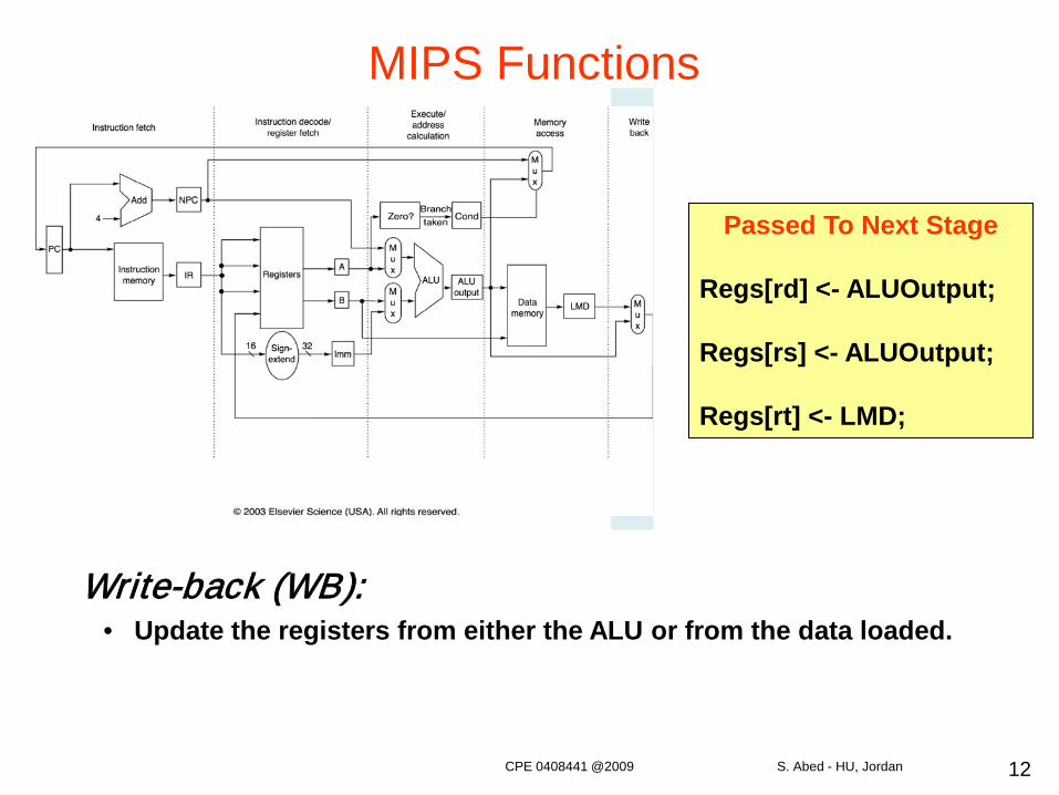
12
Passed To Next Stage
Regs[rd] <- ALUOutput;
Regs[rs] <- ALUOutput;
Regs[rt] <- LMD;
Write-back (WB):• Update the registers from either the ALU or from the data loaded.
MIPS Functions
CPE 0408441 @2009 S. Abed - HU, Jordan
13
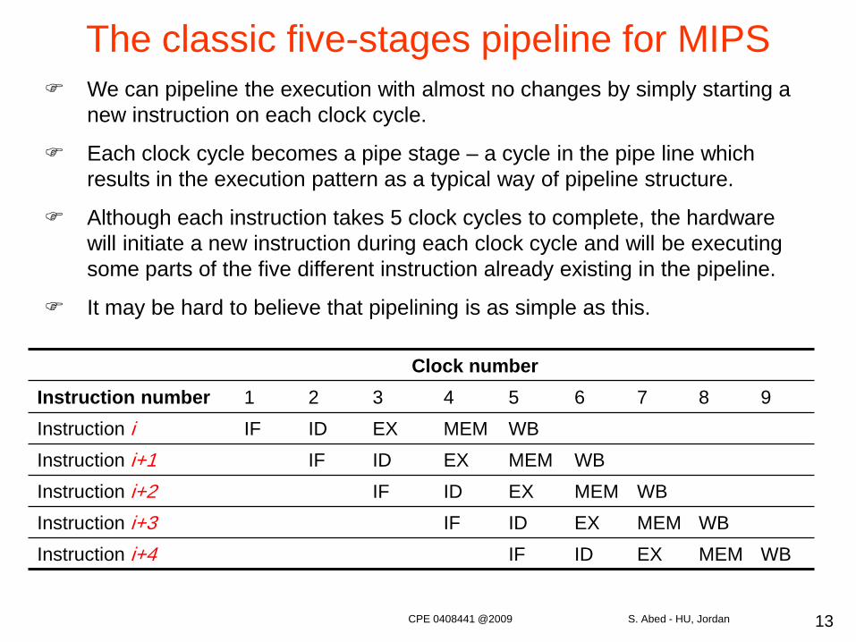
The classic five-stages pipeline for MIPS We can pipeline the execution with almost no changes by simply starting a
new instruction on each clock cycle.
Each clock cycle becomes a pipe stage – a cycle in the pipe line which results in the execution pattern as a typical way of pipeline structure.
Although each instruction takes 5 clock cycles to complete, the hardware will initiate a new instruction during each clock cycle and will be executing some parts of the five different instruction already existing in the pipeline.
It may be hard to believe that pipelining is as simple as this.
Clock numberInstruction number 1 2 3 4 5 6 7 8 9Instruction i IF ID EX MEM WBInstruction i+1 IF ID EX MEM WBInstruction i+2 IF ID EX MEM WBInstruction i+3 IF ID EX MEM WBInstruction i+4 IF ID EX MEM WB
CPE 0408441 @2009 S. Abed - HU, Jordan
14
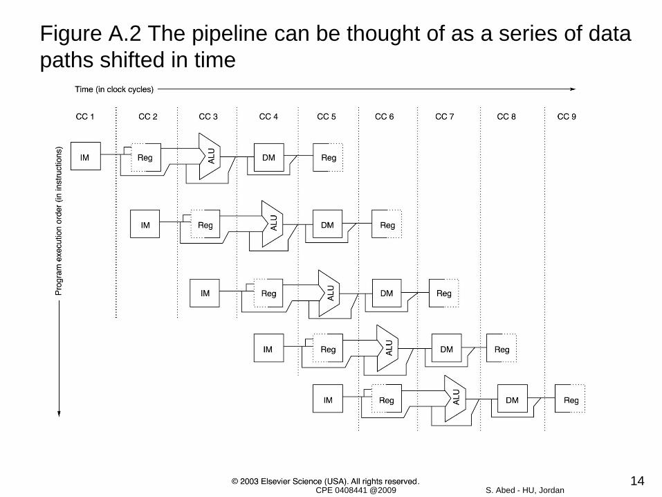
Figure A.2 The pipeline can be thought of as a series of data paths shifted in time
CPE 0408441 @2009 S. Abed - HU, Jordan
15
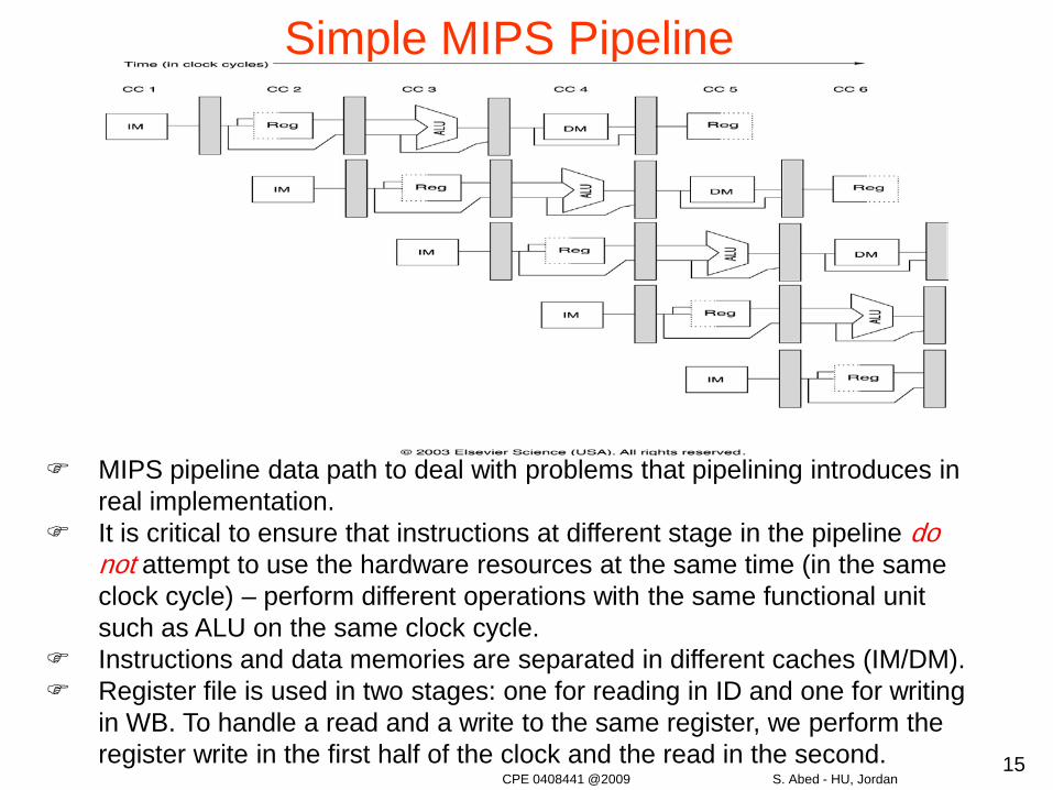
Simple MIPS Pipeline
MIPS pipeline data path to deal with problems that pipelining introduces in real implementation.
It is critical to ensure that instructions at different stage in the pipeline do not attempt to use the hardware resources at the same time (in the same clock cycle) – perform different operations with the same functional unit such as ALU on the same clock cycle.
Instructions and data memories are separated in different caches (IM/DM). Register file is used in two stages: one for reading in ID and one for writing
in WB. To handle a read and a write to the same register, we perform the register write in the first half of the clock and the read in the second.
CPE 0408441 @2009 S. Abed - HU, Jordan
16
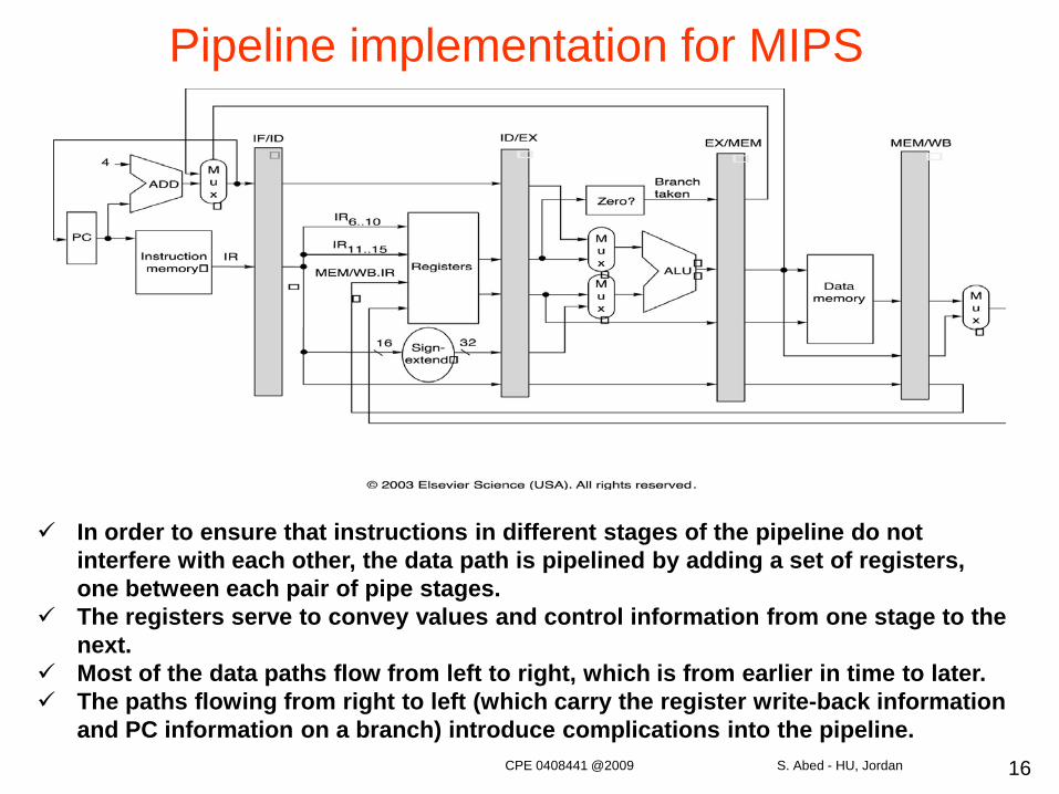
Pipeline implementation for MIPS
In order to ensure that instructions in different stages of the pipeline do not interfere with each other, the data path is pipelined by adding a set of registers, one between each pair of pipe stages.
The registers serve to convey values and control information from one stage to the next.
Most of the data paths flow from left to right, which is from earlier in time to later. The paths flowing from right to left (which carry the register write-back information
and PC information on a branch) introduce complications into the pipeline.CPE 0408441 @2009 S. Abed - HU, Jordan
17
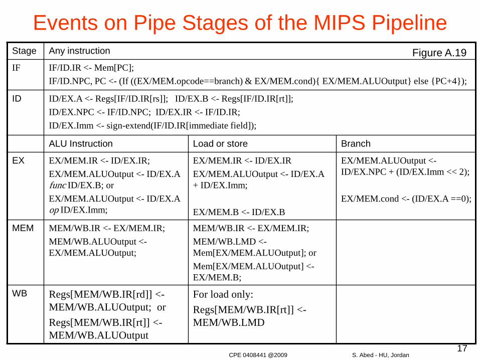
Events on Pipe Stages of the MIPS PipelineStage Any instruction
IF IF/ID.IR <- Mem[PC];IF/ID.NPC, PC <- (If ((EX/MEM.opcode==branch) & EX/MEM.cond){ EX/MEM.ALUOutput} else {PC+4});
ID ID/EX.A <- Regs[IF/ID.IR[rs]]; ID/EX.B <- Regs[IF/ID.IR[rt]];ID/EX.NPC <- IF/ID.NPC; ID/EX.IR <- IF/ID.IR;ID/EX.Imm <- sign-extend(IF/ID.IR[immediate field]);
ALU Instruction Load or store Branch
EX EX/MEM.IR <- ID/EX.IR;EX/MEM.ALUOutput <- ID/EX.A func ID/EX.B; orEX/MEM.ALUOutput <- ID/EX.A op ID/EX.Imm;
EX/MEM.IR <- ID/EX.IREX/MEM.ALUOutput <- ID/EX.A + ID/EX.Imm;
EX/MEM.B <- ID/EX.B
EX/MEM.ALUOutput <-ID/EX.NPC + (ID/EX.Imm << 2);
EX/MEM.cond <- (ID/EX.A ==0);
MEM MEM/WB.IR <- EX/MEM.IR;MEM/WB.ALUOutput <-EX/MEM.ALUOutput;
MEM/WB.IR <- EX/MEM.IR;MEM/WB.LMD <-Mem[EX/MEM.ALUOutput]; orMem[EX/MEM.ALUOutput] <-EX/MEM.B;
WB Regs[MEM/WB.IR[rd]] <-MEM/WB.ALUOutput; orRegs[MEM/WB.IR[rt]] <-MEM/WB.ALUOutput
For load only:Regs[MEM/WB.IR[rt]] <-MEM/WB.LMD
Figure A.19
CPE 0408441 @2009 S. Abed - HU, Jordan
18
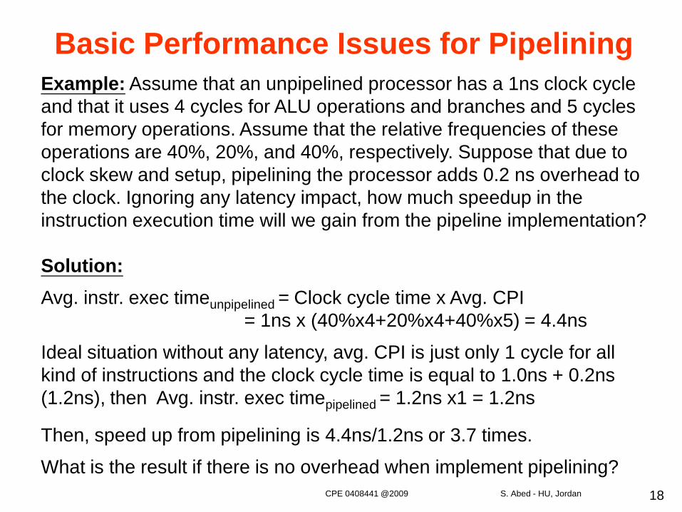
Basic Performance Issues for PipeliningExample: Assume that an unpipelined processor has a 1ns clock cycle and that it uses 4 cycles for ALU operations and branches and 5 cycles for memory operations. Assume that the relative frequencies of these operations are 40%, 20%, and 40%, respectively. Suppose that due to clock skew and setup, pipelining the processor adds 0.2 ns overhead to the clock. Ignoring any latency impact, how much speedup in the instruction execution time will we gain from the pipeline implementation?
Solution:Avg. instr. exec timeunpipelined = Clock cycle time x Avg. CPI
= 1ns x (40%x4+20%x4+40%x5) = 4.4ns
Ideal situation without any latency, avg. CPI is just only 1 cycle for all kind of instructions and the clock cycle time is equal to 1.0ns + 0.2ns (1.2ns), then Avg. instr. exec timepipelined = 1.2ns x1 = 1.2ns
Then, speed up from pipelining is 4.4ns/1.2ns or 3.7 times.
What is the result if there is no overhead when implement pipelining?CPE 0408441 @2009 S. Abed - HU, Jordan
19
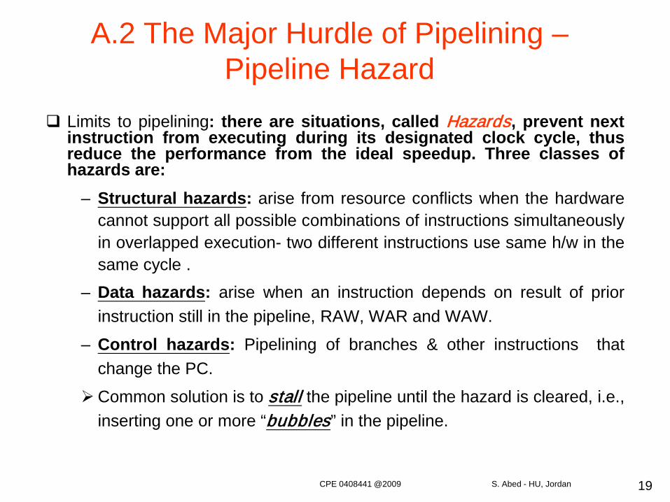
A.2 The Major Hurdle of Pipelining –Pipeline Hazard
Limits to pipelining: there are situations, called Hazards, prevent nextinstruction from executing during its designated clock cycle, thusreduce the performance from the ideal speedup. Three classes ofhazards are:
– Structural hazards: arise from resource conflicts when the hardwarecannot support all possible combinations of instructions simultaneouslyin overlapped execution- two different instructions use same h/w in thesame cycle .
– Data hazards: arise when an instruction depends on result of priorinstruction still in the pipeline, RAW, WAR and WAW.
– Control hazards: Pipelining of branches & other instructions thatchange the PC.
Common solution is to stall the pipeline until the hazard is cleared, i.e.,inserting one or more “bubbles” in the pipeline.
CPE 0408441 @2009 S. Abed - HU, Jordan
20
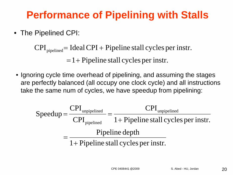
Performance of Pipelining with Stalls• The Pipelined CPI:
instr.per cycles stall Pipeline1depth Pipeline
instr.per cycles stall Pipeline1CPI
CPI CPI
Speedup dunpipeline
pipelined
dunpipeline
+=
+==
instr.per cycles stall Pipeline1
instr.per cycles stall Pipeline CPI IdealCPIpipelined
+=
+=
• Ignoring cycle time overhead of pipelining, and assuming the stages are perfectly balanced (all occupy one clock cycle) and all instructions take the same num of cycles, we have speedup from pipelining:
CPE 0408441 @2009 S. Abed - HU, Jordan
21
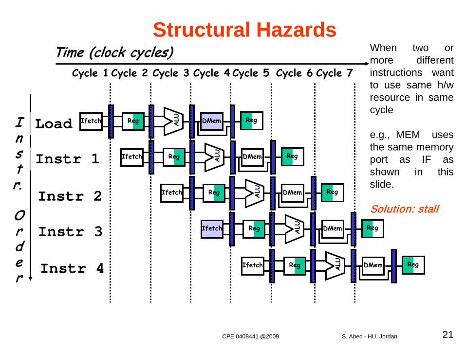
Structural HazardsWhen two ormore differentinstructions wantto use same h/wresource in samecycle
e.g., MEM usesthe same memoryport as IF asshown in thisslide.
Solution: stall
Instr.
Order
Time (clock cycles)
Load
Instr 1
Instr 2
Instr 3
Instr 4
Reg ALU DMemIfetch Reg
Reg ALU DMemIfetch Reg
Reg ALU DMemIfetch Reg
Reg ALU DMemIfetch Reg
Cycle 1 Cycle 2 Cycle 3 Cycle 4 Cycle 6 Cycle 7Cycle 5
Reg ALU DMemIfetch Reg
CPE 0408441 @2009 S. Abed - HU, Jordan
22
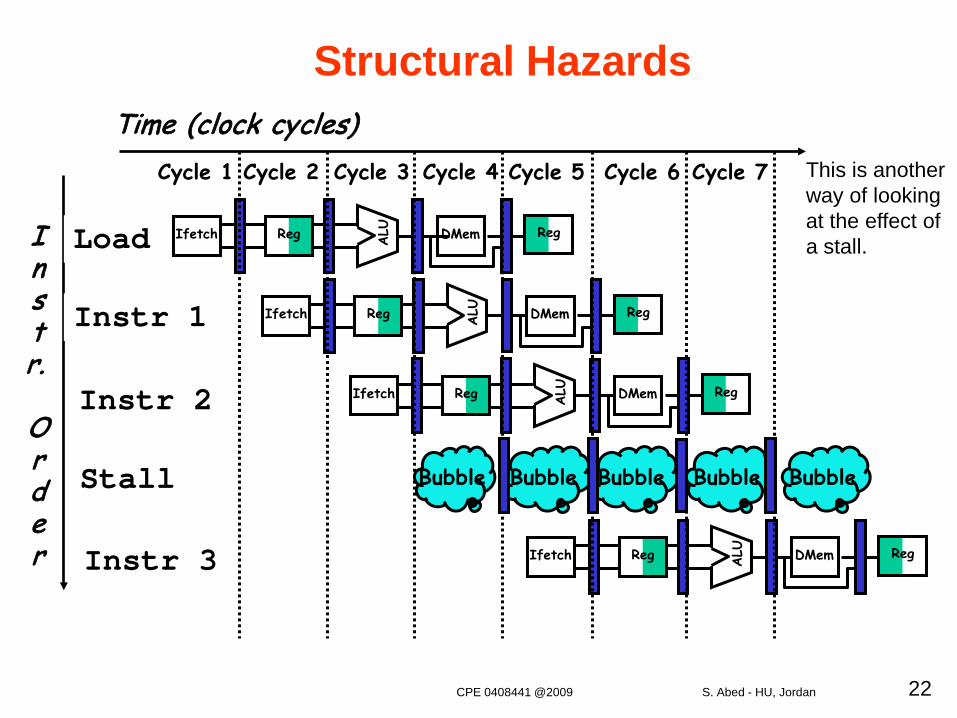
Structural Hazards
This is another way of looking at the effect of a stall.I
nstr.
Order
Time (clock cycles)
Load
Instr 1
Instr 2
Stall
Instr 3
Reg ALU DMemIfetch Reg
Reg ALU DMemIfetch Reg
Reg ALU DMemIfetch Reg
Cycle 1 Cycle 2 Cycle 3 Cycle 4 Cycle 6 Cycle 7Cycle 5
Reg ALU DMemIfetch Reg
Bubble Bubble Bubble BubbleBubble
CPE 0408441 @2009 S. Abed - HU, Jordan
23
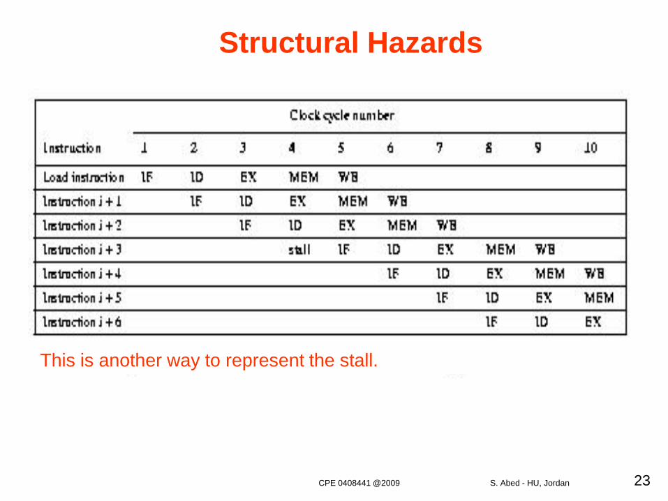
Structural Hazards
This is another way to represent the stall.
CPE 0408441 @2009 S. Abed - HU, Jordan
24
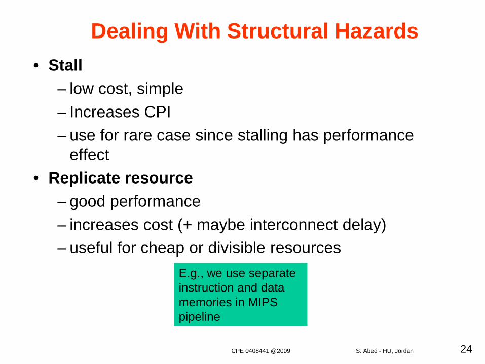
• Stall– low cost, simple – Increases CPI – use for rare case since stalling has performance
effect• Replicate resource
– good performance – increases cost (+ maybe interconnect delay) – useful for cheap or divisible resources
Dealing With Structural Hazards
E.g., we use separate instruction and data memories in MIPS pipeline
CPE 0408441 @2009 S. Abed - HU, Jordan
25
Data Hazards• Data hazards occur when the pipeline changes the order of
read/write accesses to operands (registers) so that the orderdiffers from the order seen by sequentially executinginstructions on an unpipelined processor.
• Where there’s real trouble is when we have:
instruction Ainstruction B,
and B manipulates (reads or writes) data before A does. Thisviolates the order of the instructions, since the architectureimplies that A completes entirely before B is executed.
CPE 0408441 @2009 S. Abed - HU, Jordan
26
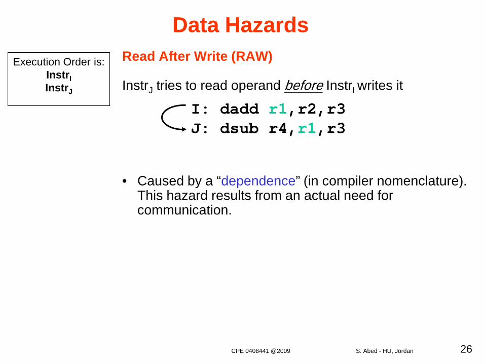
Read After Write (RAW)
InstrJ tries to read operand before InstrI writes it
• Caused by a “dependence” (in compiler nomenclature). This hazard results from an actual need for communication.
Execution Order is:InstrIInstrJ
I: dadd r1,r2,r3J: dsub r4,r1,r3
Data Hazards
CPE 0408441 @2009 S. Abed - HU, Jordan
27
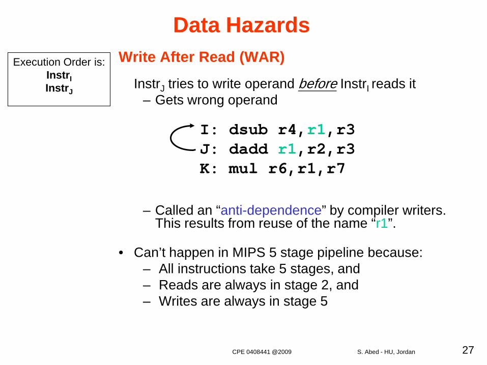
Write After Read (WAR)
InstrJ tries to write operand before InstrI reads it– Gets wrong operand
– Called an “anti-dependence” by compiler writers.This results from reuse of the name “r1”.
• Can’t happen in MIPS 5 stage pipeline because:– All instructions take 5 stages, and– Reads are always in stage 2, and – Writes are always in stage 5
Execution Order is:InstrIInstrJ
I: dsub r4,r1,r3 J: dadd r1,r2,r3K: mul r6,r1,r7
Data Hazards
CPE 0408441 @2009 S. Abed - HU, Jordan
28
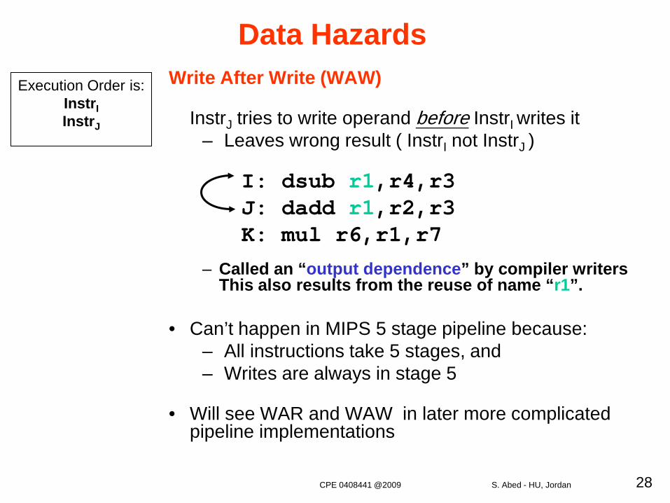
Write After Write (WAW)
InstrJ tries to write operand before InstrI writes it– Leaves wrong result ( InstrI not InstrJ )
– Called an “output dependence” by compiler writersThis also results from the reuse of name “r1”.
• Can’t happen in MIPS 5 stage pipeline because: – All instructions take 5 stages, and – Writes are always in stage 5
• Will see WAR and WAW in later more complicated pipeline implementations
Execution Order is:InstrIInstrJ
I: dsub r1,r4,r3 J: dadd r1,r2,r3K: mul r6,r1,r7
Data Hazards
CPE 0408441 @2009 S. Abed - HU, Jordan
29
• Simple Solution to RAW • Hardware detects RAW and stalls until the result is written into
the register + low cost to implement, simple -- reduces # instruction executed per cycle
• Minimizing RAW stalls: Forwarding (also called bypassing)• Key insight: the result is not really needed by the current
instruction until after the previous instruction actually produces it.• The ALU result from both the EX/MEM and MEM/WB pipeline
registers is always fed back to the ALU inputs.• If the forwarding hardware detects that the previous ALU
operation has written the register corresponding to a source for the current ALU operation, control logic selects the forwarded result as the ALU input rather than the value read from the register file.
Solutions to Data Hazards
CPE 0408441 @2009 S. Abed - HU, Jordan
30
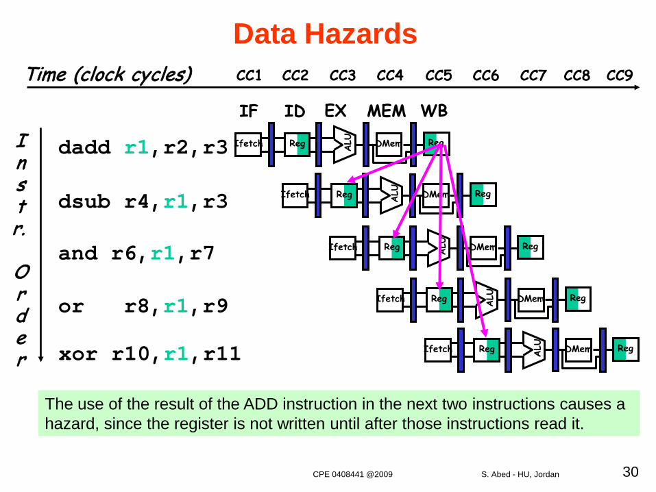
The use of the result of the ADD instruction in the next two instructions causes a hazard, since the register is not written until after those instructions read it.
Instr.
Order
dadd r1,r2,r3
dsub r4,r1,r3
and r6,r1,r7
or r8,r1,r9
xor r10,r1,r11
Reg ALU DMemIfetch Reg
Reg ALU DMemIfetch Reg
Reg ALU DMemIfetch Reg
Reg ALU DMemIfetch Reg
Reg ALU DMemIfetch Reg
IF ID EX MEM WB
Data HazardsTime (clock cycles) CC1 CC2 CC3 CC4 CC6 CC7CC5 CC8 CC9
CPE 0408441 @2009 S. Abed - HU, Jordan
31
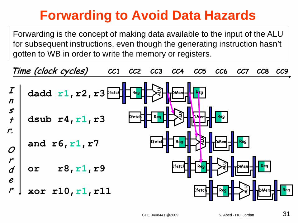
Forwarding is the concept of making data available to the input of the ALU for subsequent instructions, even though the generating instruction hasn’t gotten to WB in order to write the memory or registers.
Reg ALU DMemIfetch Reg
Reg ALU DMemIfetch Reg
Reg ALU DMemIfetch Reg
Reg ALU DMemIfetch Reg
Reg ALU DMemIfetch Reg
Forwarding to Avoid Data Hazards
Instr.
Order
dadd r1,r2,r3
dsub r4,r1,r3
and r6,r1,r7
or r8,r1,r9
xor r10,r1,r11
Time (clock cycles) CC1 CC2 CC3 CC4 CC6 CC7CC5 CC8 CC9
CPE 0408441 @2009 S. Abed - HU, Jordan
32
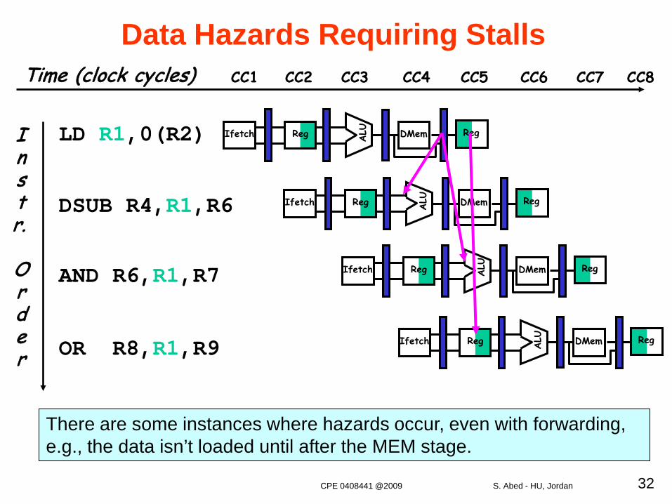
There are some instances where hazards occur, even with forwarding, e.g., the data isn’t loaded until after the MEM stage.
Instr.
Order
LD R1,0(R2)
DSUB R4,R1,R6
AND R6,R1,R7
OR R8,R1,R9
Reg ALU DMemIfetch Reg
Reg ALU DMemIfetch Reg
Reg ALU DMemIfetch Reg
Reg ALU DMemIfetch Reg
Data Hazards Requiring StallsTime (clock cycles) CC1 CC2 CC3 CC4 CC6 CC7CC5 CC8
CPE 0408441 @2009 S. Abed - HU, Jordan
33
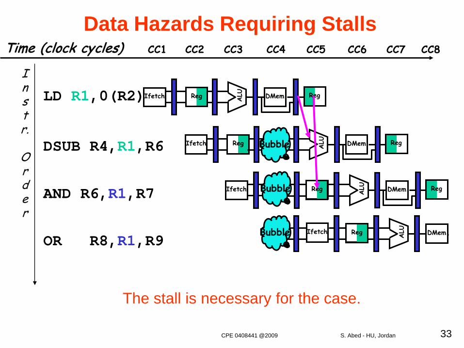
OR R8,R1,R9
Instr.
Order
LD R1,0(R2)
DSUB R4,R1,R6
AND R6,R1,R7
Reg ALU DMemIfetch Reg
RegIfetch ALU DMem RegBubble
Ifetch ALU DMem RegBubble Reg
Ifetch
ALU DMemBubble Reg
Data Hazards Requiring Stalls
The stall is necessary for the case.
Time (clock cycles) CC1 CC2 CC3 CC4 CC6 CC7CC5 CC8
CPE 0408441 @2009 S. Abed - HU, Jordan
34
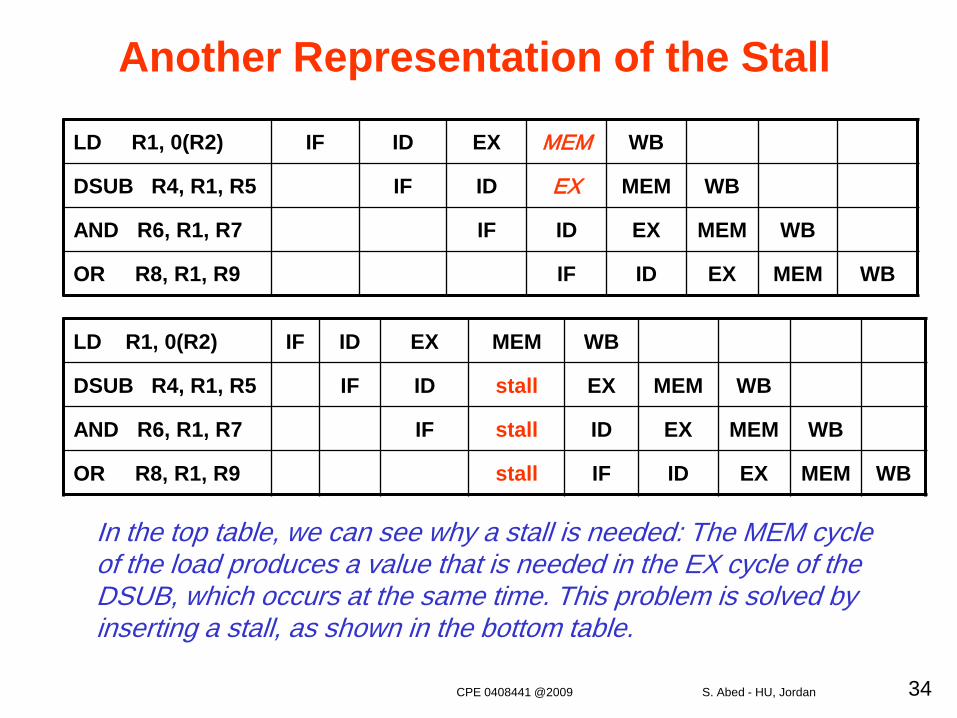
LD R1, 0(R2) IF ID EX MEM WB
DSUB R4, R1, R5 IF ID EX MEM WB
AND R6, R1, R7 IF ID EX MEM WB
OR R8, R1, R9 IF ID EX MEM WB
LD R1, 0(R2) IF ID EX MEM WB
DSUB R4, R1, R5 IF ID stall EX MEM WB
AND R6, R1, R7 IF stall ID EX MEM WB
OR R8, R1, R9 stall IF ID EX MEM WB
Another Representation of the Stall
In the top table, we can see why a stall is needed: The MEM cycleof the load produces a value that is needed in the EX cycle of the DSUB, which occurs at the same time. This problem is solved byinserting a stall, as shown in the bottom table.
CPE 0408441 @2009 S. Abed - HU, Jordan
35
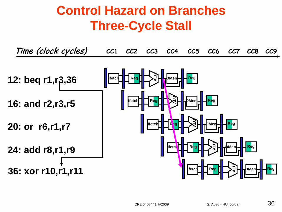
Control Hazards
• A control hazard happens when we need to find thedestination of a branch, and can’t fetch any newinstructions until we know that destination.
– If instruction i is a taken branch, then the PC is normally notchanged until the end of ID
• Control hazards can cause a greater performanceloss than do data hazards.
CPE 0408441 @2009 S. Abed - HU, Jordan
36
Control Hazard on Branches Three-Cycle Stall
12: beq r1,r3,36
16: and r2,r3,r5
20: or r6,r1,r7
24: add r8,r1,r9
36: xor r10,r1,r11
Reg ALU
DMemIfetch Reg
Reg ALU
DMemIfetch Reg
Reg ALU
DMemIfetch Reg
Reg ALU
DMemIfetch Reg
Reg ALU
DMemIfetch Reg
Time (clock cycles) CC1 CC2 CC3 CC4 CC6 CC7CC5 CC8 CC9
CPE 0408441 @2009 S. Abed - HU, Jordan
37
Branch Stall Impact• If CPI = 1, 30% branch, Stall 3 cycles => new CPI = 1.9!
• Two solutions to this dramatic increase:– Determine branch taken or not sooner, AND– Compute target address earlier
• MIPS branch tests if register = 0 or ^ 0
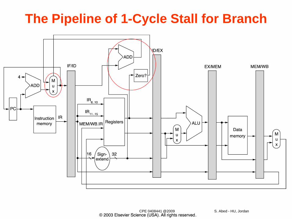
• MIPS Solution:– Move Zero test to ID stage– Adder to calculate target address in ID stage– 1 clock cycle penalty for branch versus 3
CPE 0408441 @2009 S. Abed - HU, Jordan
38
The Pipeline of 1-Cycle Stall for Branch
CPE 0408441 @2009 S. Abed - HU, Jordan
39
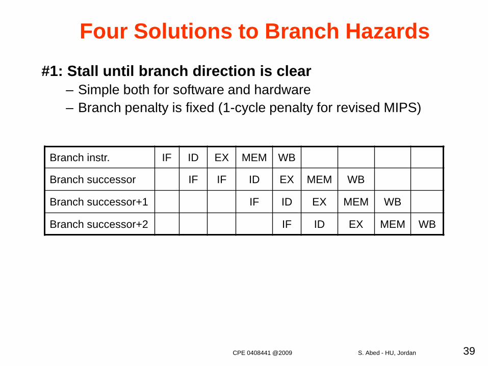
Four Solutions to Branch Hazards#1: Stall until branch direction is clear
– Simple both for software and hardware– Branch penalty is fixed (1-cycle penalty for revised MIPS)
Branch instr. IF ID EX MEM WB
Branch successor IF IF ID EX MEM WB
Branch successor+1 IF ID EX MEM WB
Branch successor+2 IF ID EX MEM WB
CPE 0408441 @2009 S. Abed - HU, Jordan
40
Four Solutions to Branch Hazards
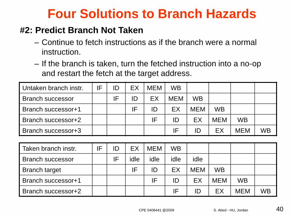
Untaken branch instr. IF ID EX MEM WBBranch successor IF ID EX MEM WBBranch successor+1 IF ID EX MEM WBBranch successor+2 IF ID EX MEM WBBranch successor+3 IF ID EX MEM WB
Taken branch instr. IF ID EX MEM WBBranch successor IF idle idle idle idleBranch target IF ID EX MEM WBBranch successor+1 IF ID EX MEM WBBranch successor+2 IF ID EX MEM WB
#2: Predict Branch Not Taken– Continue to fetch instructions as if the branch were a normal
instruction.– If the branch is taken, turn the fetched instruction into a no-op
and restart the fetch at the target address.
CPE 0408441 @2009 S. Abed - HU, Jordan
41
Four Solutions to Branch Hazards#3: Predict Branch Taken
– As soon as the branch is decoded and the target address is computed, we assume the branch to be taken and begin fetching and executing at the target.
– But haven’t calculated the target address before we know the branch outcome in MIPS
• MIPS still incurs 1-cycle branch penalty
• Useful for other machines on which the target address is known before the branch outcome
CPE 0408441 @2009 S. Abed - HU, Jordan
42
#4: Delayed Branch– The execution cycle with a branch delay of one is branch instructionsequential successor1branch target if taken
– The sequential successor is in the branch delay slot.– The instruction in the branch delay slot is executed whether
or not the branch is taken (for zero cycle penalty)
Four Solutions to Branch Hazards
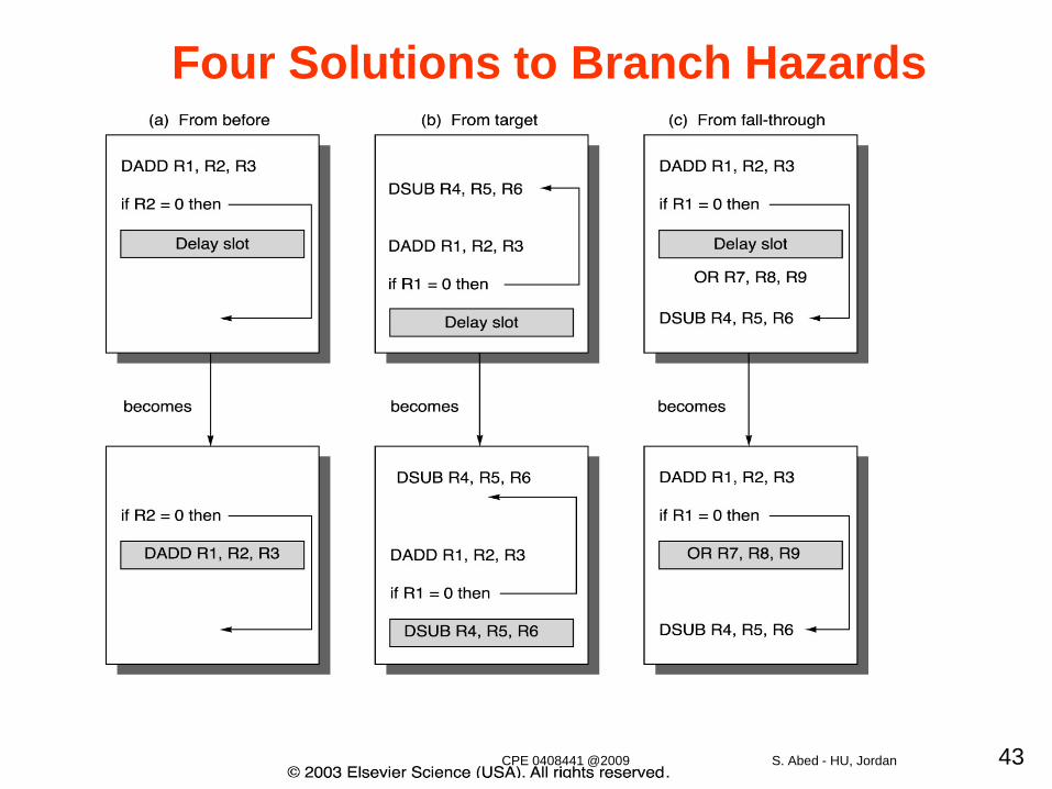
•Where to get instructions to fill branch delay slot?– From before branch instruction– From target address: only valuable when branch taken– From fall through: only valuable when branch not taken– Canceling or nullifying branches allow more slots to be filled (non-
zero cycle penalty, its value depends on the rate of correct predication)
– the delay-slot instruction is turned into a no-op if incorrectly predicted
CPE 0408441 @2009 S. Abed - HU, Jordan
43
Four Solutions to Branch Hazards
CPE 0408441 @2009 S. Abed - HU, Jordan
44
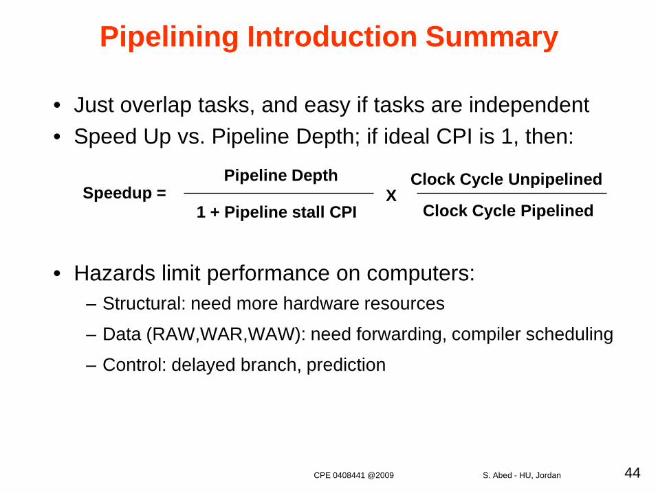
Pipelining Introduction Summary
• Just overlap tasks, and easy if tasks are independent• Speed Up vs. Pipeline Depth; if ideal CPI is 1, then:
• Hazards limit performance on computers:– Structural: need more hardware resources
– Data (RAW,WAR,WAW): need forwarding, compiler scheduling
– Control: delayed branch, prediction
Speedup =Pipeline Depth
1 + Pipeline stall CPIX
Clock Cycle Unpipelined
Clock Cycle Pipelined
CPE 0408441 @2009 S. Abed - HU, Jordan