Embed Size (px)
DESCRIPTION
Basic Communication theory
Citation preview


Most signals in electronic communications systems can be represented by sine or cosine waves, or a combination of sine/cosine
Mathematically, a single-frequency voltage or current waveform is
oror
)2sin()( ftVtv )2cos()( ftVtv
)2sin()( ftIti )2cos()( ftIti
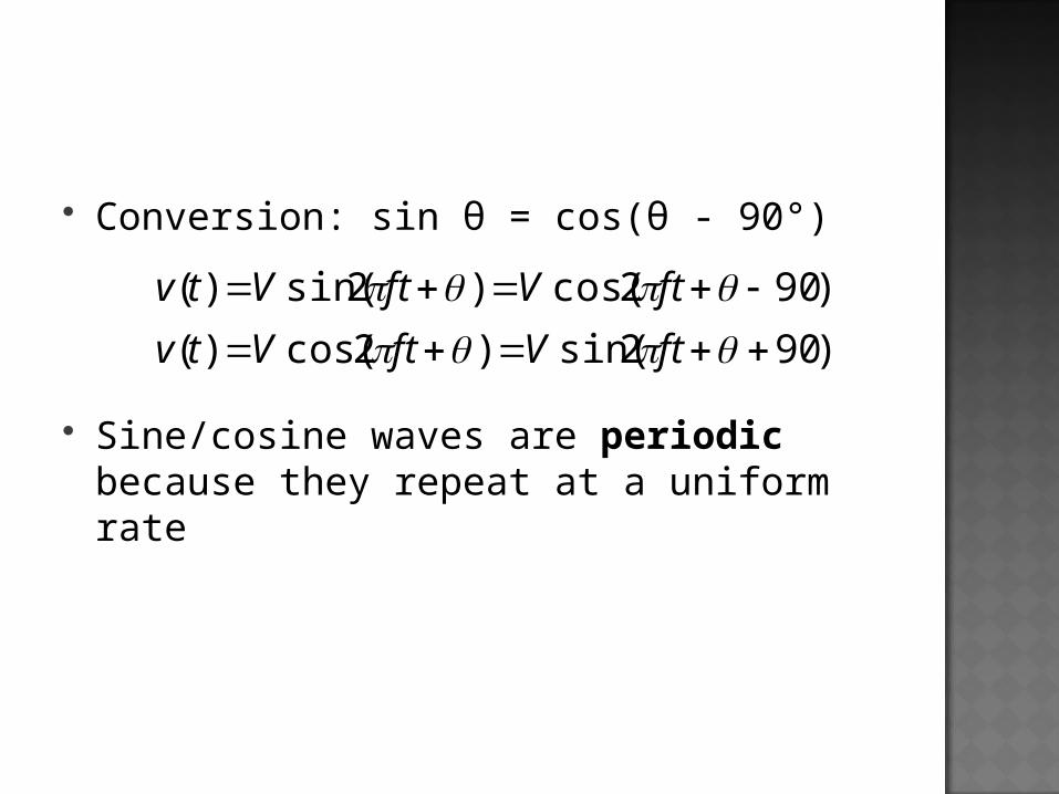
Conversion: sin θ = cos(θ - 90°)
Sine/cosine waves are periodic because they repeat at a uniform rate
)902cos()2sin()( ftVftVtv
)902sin()2cos()( ftVftVtv

Convert this signal from sine representation to cosine representation: v(t) = 2 sin (30t – 30)

Convert this signal from sine representation to cosine representation: v(t) = 2 cos (10t)

1)Time DomainDescription of signal with respect to timeAmplitude vs. TimeE.g. instrument: Oscilloscope
2) Frequency DomainDescription of signal with respect to
frequencyAmplitude vs. FrequencyE.g. instrument: Spectrum analyzer


Complex wavesany repetitive waveform that is comprised
of more than one harmonically related sine or cosine wave
E.g. square waves, rectangular waves, triangular waves
To analyze a complex periodic wave, we can use a mathematical series called Fourier series

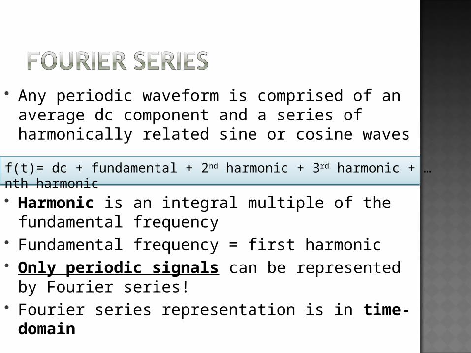
Any periodic waveform is comprised of an average dc component and a series of harmonically related sine or cosine waves
Harmonic is an integral multiple of the fundamental frequency
Fundamental frequency = first harmonic Only periodic signals can be represented
by Fourier series! Fourier series representation is in time-
domain
f(t)= dc + fundamental + 2nd harmonic + 3rd harmonic + …nth harmonic

For a continuous-time periodic signal x(t)
where ak is a coefficient defined by
k
k
tT
jk
k
k
k
tjkk eaeatx
2
0)(
T
tT
jk
T
tjkk dtetx
Tdtetx
Ta
2
)(1
)(1
0

Sine and cosine signals can be represented in exponential Fourier series
For sine and cosine, use Euler’s relation:
tjtj
tjtj
eej
t
eet
00
00
2
1)sin(
2
1)cos(
0
0
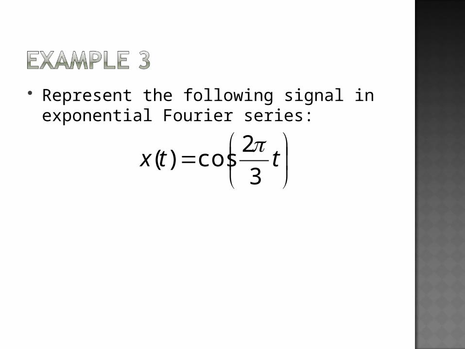
Represent the following signal in exponential Fourier series:
ttx3
2cos)(

Fourier Transform gives the signal representation in frequency domain
Fourier Transform can be used for all signals, whether periodic or not

Is used to transform a continuous-time signal described in time into a continuous-time signal described in frequency
Fourier Transform:
Inverse Fourier Transform:
dtetxjX tj )()(
dejXtx tj)(2
1)(

x(t) X(jω)
X(jω) x(t)
Fourier Transform table (Table 4.2) is available for reference. The table gives the X(jω) for common signals
Fourier Transform
InverseFourierTransform

Let x(t) = sin (πt)Find the Fourier series representation of x(t)Find the Fourier Transform of x(t)

Fourier Transform:
Inverse Fourier Transform:
Discrete-time Fourier Transform table (Table 5.2) is also available
n
njj enxeX ][)(
2
)(2
1][ deeXnx jj
x[n] X(ejω)
X(ejω) x[n]
Fourier Transform
Inverse Fourier Transform

Find Fourier Transform for
][2
1][ nunx
n

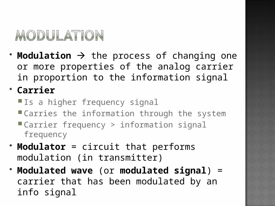
Modulation the process of changing one or more properties of the analog carrier in proportion to the information signal
Carrier Is a higher frequency signal Carries the information through the system Carrier frequency > information signal frequency
Modulator = circuit that performs modulation (in transmitter)
Modulated wave (or modulated signal) = carrier that has been modulated by an info signal

Demodulation = converts the modulated carrier back to its original info signal (removes information signal from the carrier)
Demodulation is the reverse of the modulation process
Demodulator = circuit which performs demodulation in the receiver

In analog communication systems, both info and carrier are analog signals
In digital communication systems, there are many other techniques such as digital transmission and digital radioDigital transmission
No analog carrier Digital pulses are transferred
Digital radio Modulated signal & demodulated signal are
digital pulses Transmit digitally modulated analog
carriers

Why modulation is important in electronic communications: It is extremely difficult to radiate low-
frequency signals from an antenna in the form of electromagnetic energy
Information signals often occupy the same frequency band, so they may interfere each other if they are transmitted at the same time
Example: Voice & music – 300 Hz to 15 kHz. Each FM
station will convert its information to a different frequency band/channel
Channel = a specific band of frequencies which are allocated for a particular service

Multiplexing = combining several signals for simultaneous transmission over the same channel
Demultiplexing = extracting individual signals from a combined signal
Example techniques:Frequency-division multiplexing (FDM)Time-division multiplexing (TDM)Code-division multiplexing (CDM)Wavelength-division multiplexing (WDM)

Analog communication:Advantage:
Simpler design than digital, because analog modulation requires relatively mild changes to the information signal waveform in order to transmit over a channel
Disadvantage: Difficult to build, because of the strict
requirements on linearity and system adjustments

Digital communication:Advantage:
More tolerant to physical effects such as temperature variations and mechanical vibrations
Disadvantage: More power is required for transmission
compared to analog


Nyquist sampling theorem states that for a sample to be reproduced accurately, the minimum sampling rate must be twice the highest input frequency
Sampling rate (fs) ≥ 2 × highest input frequency (fa)
If less than twice, aliasing may occur

Bandwidth of an information signal = difference between highest and lowest frequencies contained in the information
Bandwidth of a communications channel = difference between highest and lowest frequencies that the channel will allow to pass through it
Channel bandwidth > Signal bandwidth

Filter categories: Low pass filter
Allows frequencies lower than the cutoff frequency Blocks frequencies higher than the cutoff frequency
High pass filter Allows frequencies higher than the cutoff frequency Blocks frequencies lower than the cutoff frequency
Band pass filter Allows frequencies in between the lower cutoff
frequency and the upper cutoff frequencies Blocks other frequencies
Band stop filter Blocks frequencies in between the lower cutoff
frequency and the upper cutoff frequencies Allows other frequencies

(a) Low pass filter (c) Band pass filter(b) High pass filter (d) Band stop filter

Electrical noise = any unwanted electrical energy that falls within the passband of the signal
Noise categories:Correlated
No signal, no noise!Uncorrelated
Always present, regardless of signal Sources:
External – atmospheric, extraterrestial, solar, cosmic, man-made (industrial)
Internal – shot noise, transit time noise, thermal noise

External generated outside the circuit Atmospheric
Naturally occurring electrical disturbances in Earth’s atmosphere
Static electricity Extra-terrestrial
Electrical signals from outside Earth’s atmosphere (from our galaxy & other galaxies)
Solar Noise from sun’s heat
Cosmic Noise that are continuously distributed throughout the galaxies
Man-made From machines

Internal electrical interferences generated within the circuit
Shot Caused by the random arrival of carriers at the
output element of an electronic device Transit time
Modifications to a stream of carriers as they pass from the input to the output of the device
Thermal Associated with the rapid and random movement
of electrons within a conductor due to thermal agitation
Increases as the number of devices increases

Is produced by nonlinear amplification Types:
Harmonic distortion Intermodulation distortion

InterferenceWhen information signals from one source
produces frequencies that fall outside their allocated bandwidth and interfere with information signal from another source
Signal-to-noise ratioor
Ps = signal powerPn = noise power
n
s
P
P
N
S
n
s
P
PdB
N
S10log10)(
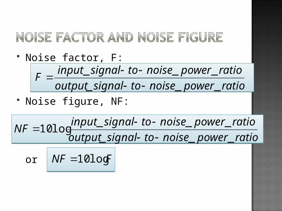
Noise factor, F:
Noise figure, NF:
or
ratiopowernoisetosignaloutput
ratiopowernoisetosignalinputF
___
___
ratiopowernoisetosignaloutput
ratiopowernoisetosignalinputNF
___
___log10
FNF log10
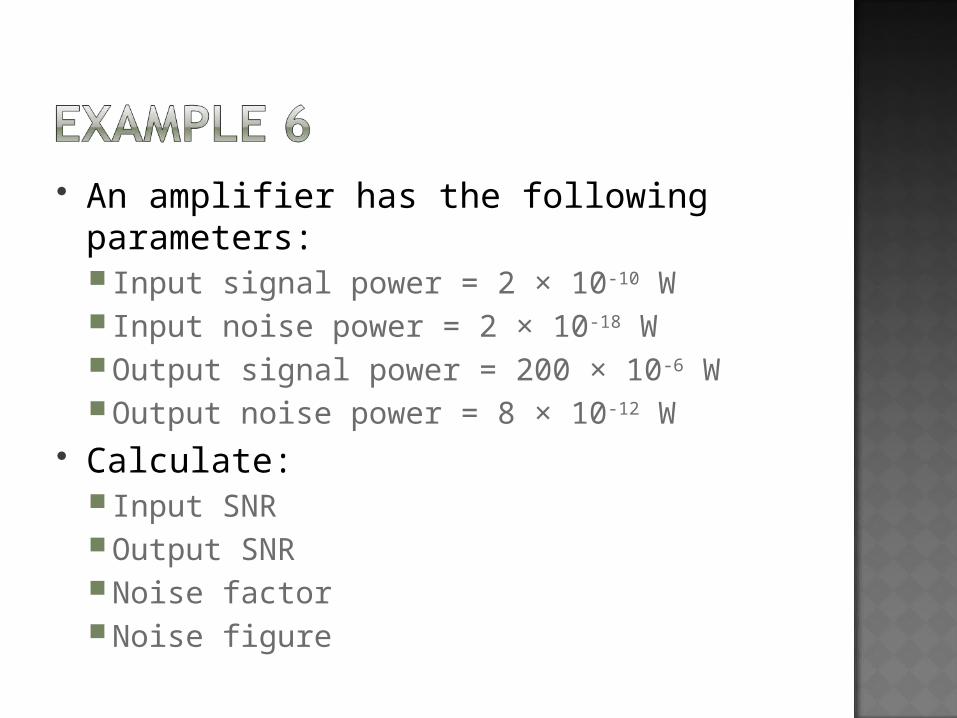
An amplifier has the following parameters: Input signal power = 2 × 10⁻¹⁰ W Input noise power = 2 × 10-18 WOutput signal power = 200 × 10-6 WOutput noise power = 8 × 10-12 W
Calculate: Input SNROutput SNRNoise factorNoise figure