Embed Size (px)
Citation preview

Project
Digital Tachometer

TEACHER NAME : SIR NAJAM US SAQIB
Group membersMuhammad Usman(SP14-BEE-019)Muhammad Bilal(SP14-BEE-034)Uzair ul Hassan (SP14-BEE-018)
Waseem Iqbal(SP14-BEE-04)Orangzaib Yousaf(SP14-BE-110)
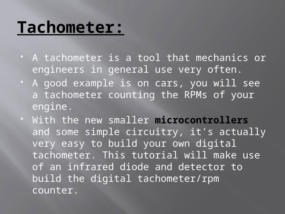
Tachometer: A tachometer is a tool that mechanics or
engineers in general use very often. A good example is on cars, you will see a
tachometer counting the RPMs of your engine.
With the new smaller microcontrollers and some simple circuitry, it's actually very easy to build your own digital tachometer. This tutorial will make use of an infrared diode and detector to build the digital tachometer/rpm counter.
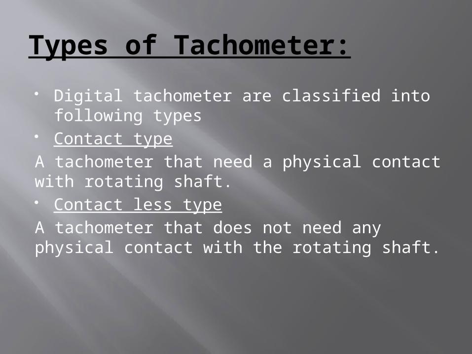
Types of Tachometer:
Digital tachometer are classified into following types
Contact typeA tachometer that need a physical contact with rotating shaft. Contact less typeA tachometer that does not need any physical contact with the rotating shaft.
Measurement types:
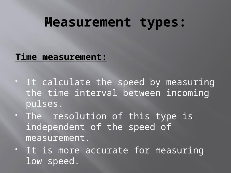
Time measurement:
It calculate the speed by measuring the time interval between incoming pulses.
The resolution of this type is independent of the speed of measurement.
It is more accurate for measuring low speed.
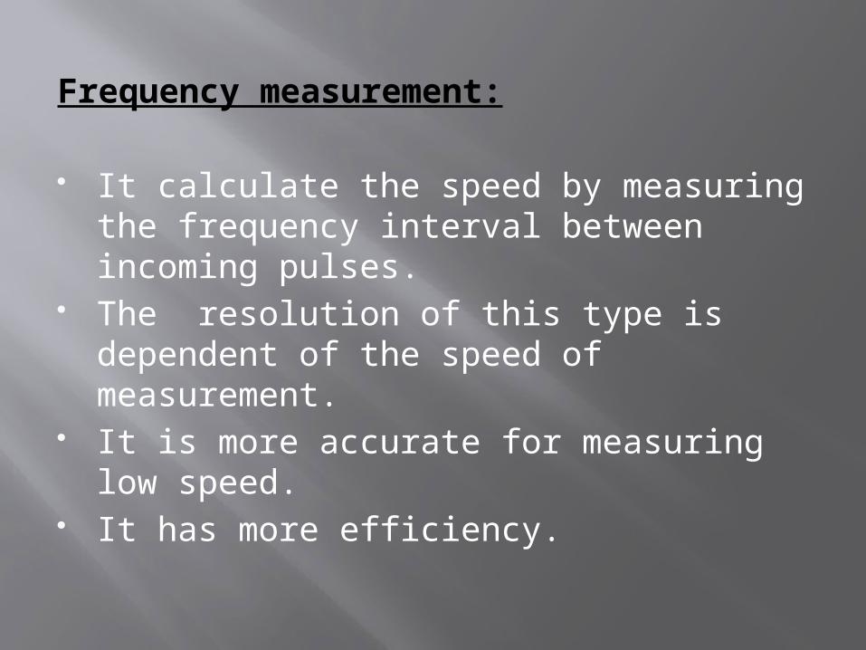
Frequency measurement:
It calculate the speed by measuring the frequency interval between incoming pulses.
The resolution of this type is dependent of the speed of measurement.
It is more accurate for measuring low speed.
It has more efficiency.
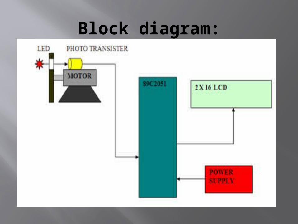
Block diagram:
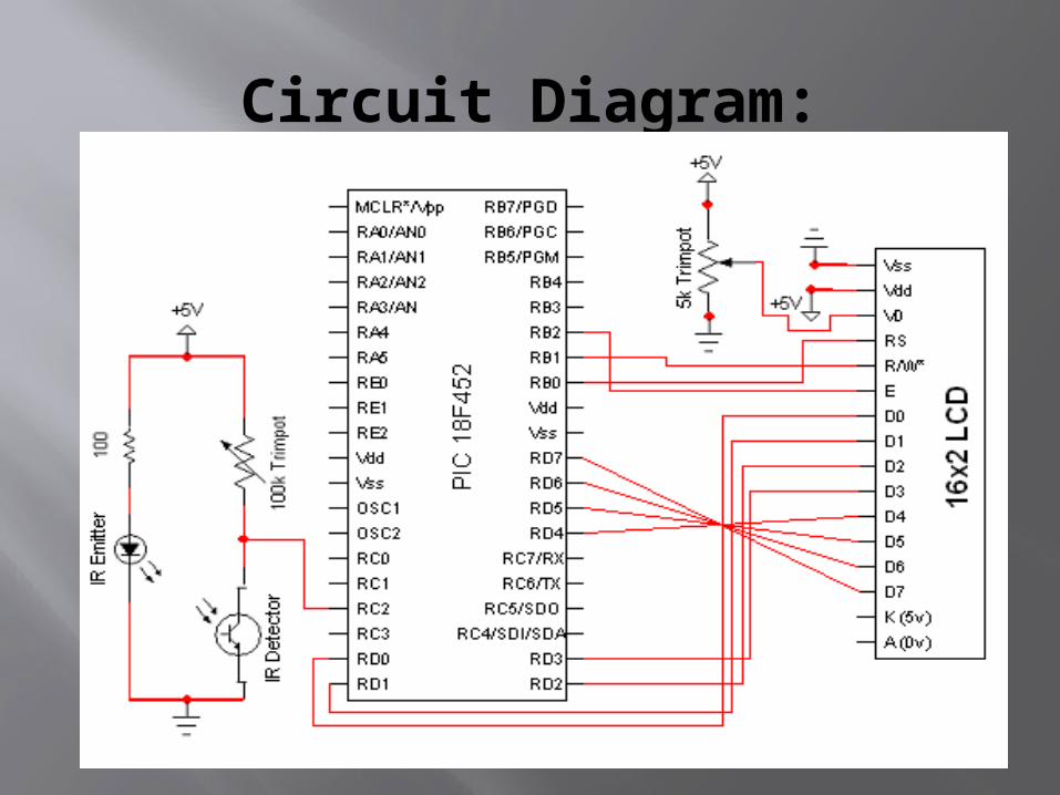
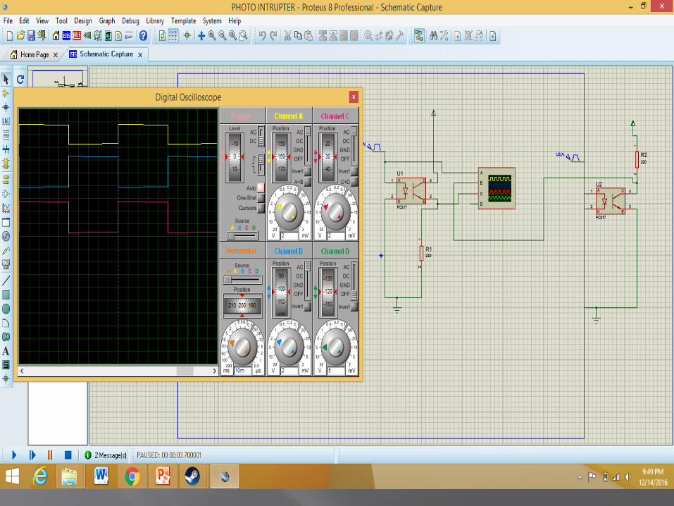
Circuit Diagram:
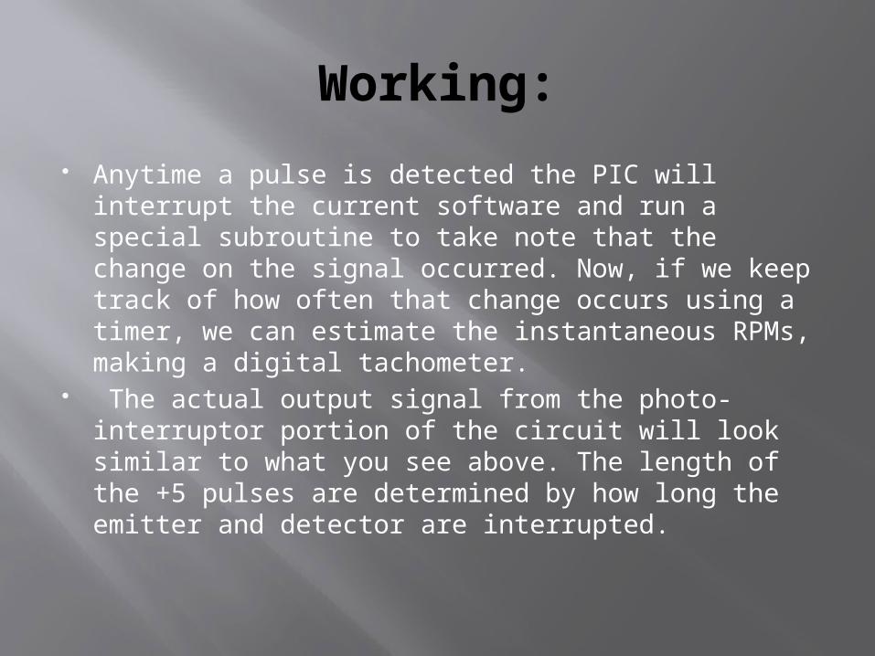
Working: Anytime a pulse is detected the PIC will interrupt
the current software and run a special subroutine to take note that the change on the signal occurred. Now, if we keep track of how often that change occurs using a timer, we can estimate the instantaneous RPMs, making a digital tachometer.
The actual output signal from the photo-interruptor portion of the circuit will look similar to what you see above. The length of the +5 pulses are determined by how long the emitter and detector are interrupted.
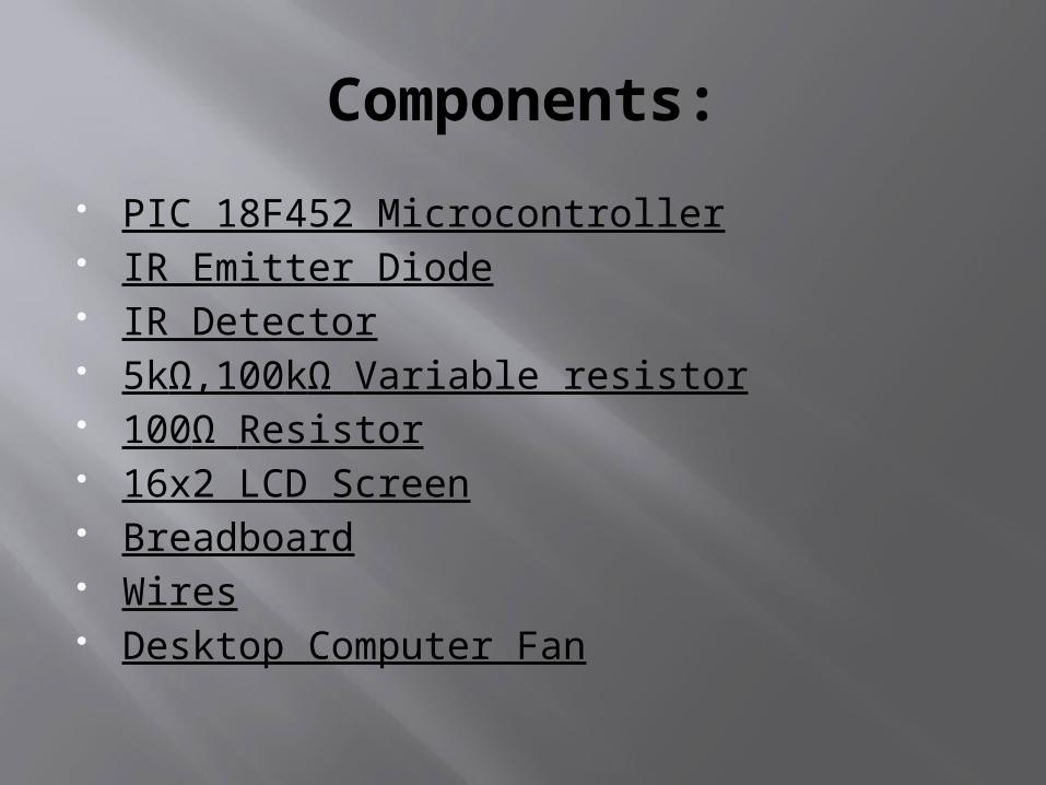
Components: PIC 18F452 Microcontroller IR Emitter Diode IR Detector 5kΩ,100kΩ Variable resistor 100Ω Resistor 16x2 LCD Screen Breadboard Wires Desktop Computer Fan
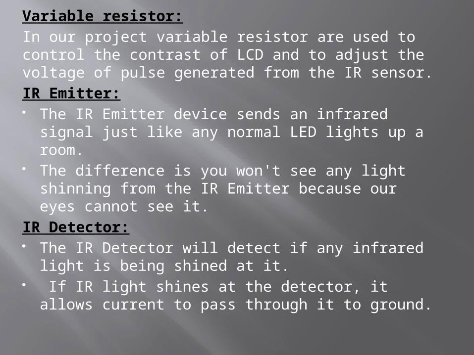
Variable resistor:In our project variable resistor are used to control the contrast of LCD and to adjust the voltage of pulse generated from the IR sensor.IR Emitter: The IR Emitter device sends an infrared signal
just like any normal LED lights up a room. The difference is you won't see any light
shinning from the IR Emitter because our eyes cannot see it.
IR Detector: The IR Detector will detect if any infrared light
is being shined at it. If IR light shines at the detector, it allows
current to pass through it to ground.
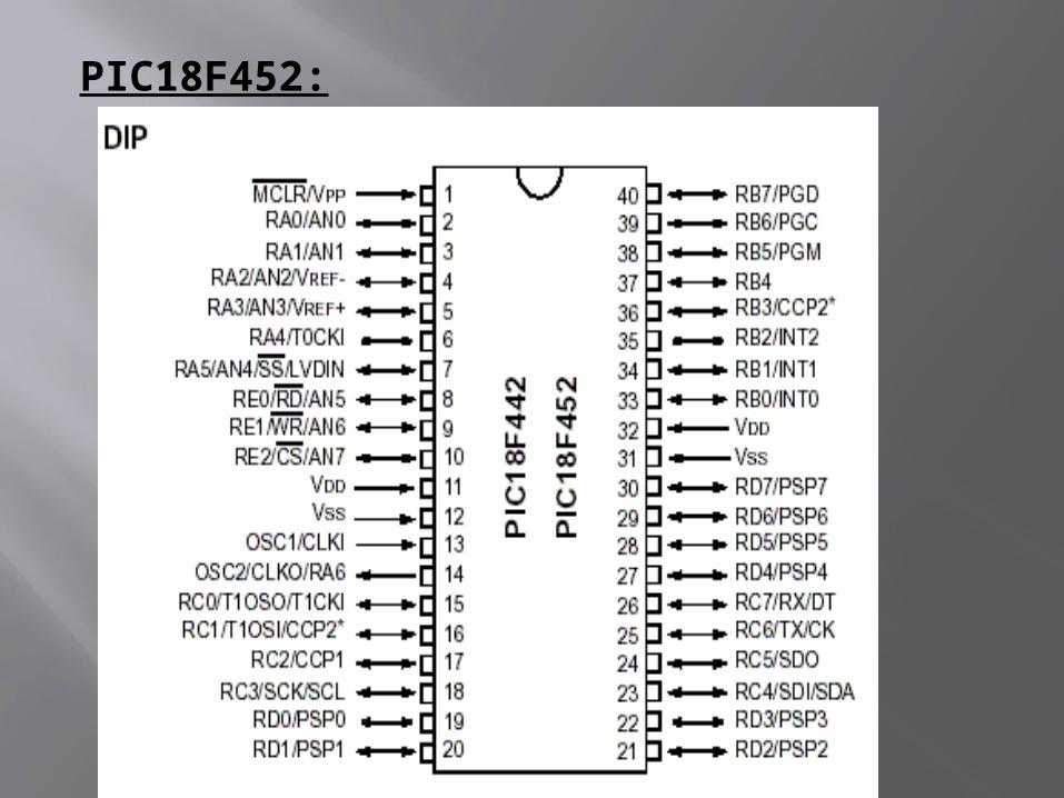
PIC18F452:

Why we don't used the IR sensor instead of LDR.The reason is that while using the LDR all visible lights are detected on the LDR and it will may effect our calculation.While the IR sensor will only detect Infrared light. 16x4 LCD:
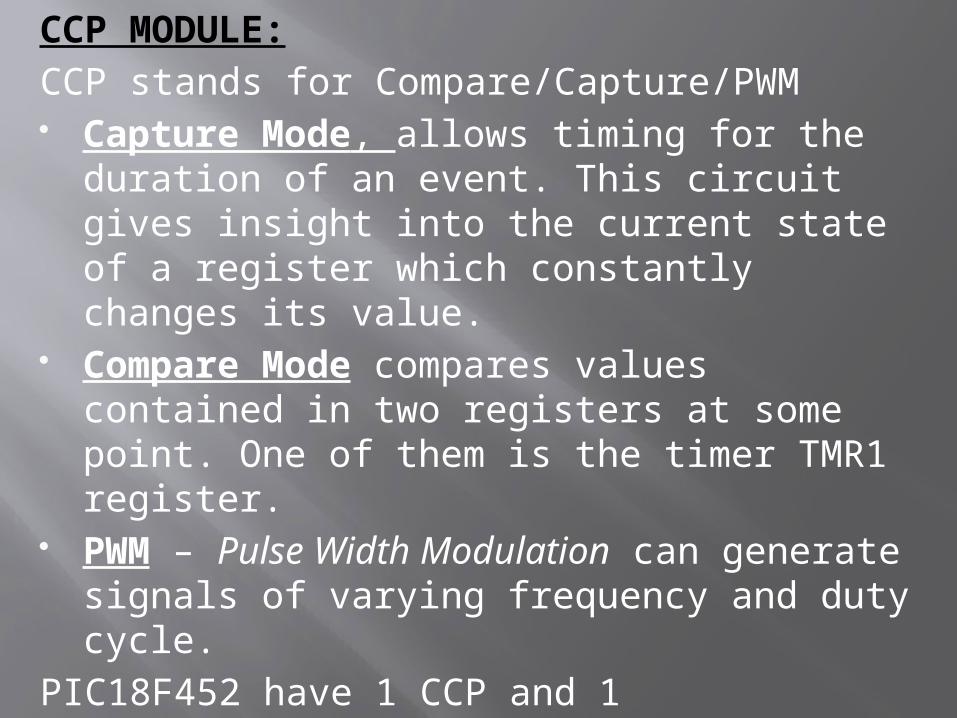
CCP MODULE:CCP stands for Compare/Capture/PWM Capture Mode, allows timing for the
duration of an event. This circuit gives insight into the current state of a register which constantly changes its value.
Compare Mode compares values contained in two registers at some point. One of them is the timer TMR1 register.
PWM – Pulse Width Modulation can generate signals of varying frequency and duty cycle.
PIC18F452 have 1 CCP and 1 ECCP(Enhanced CCP)
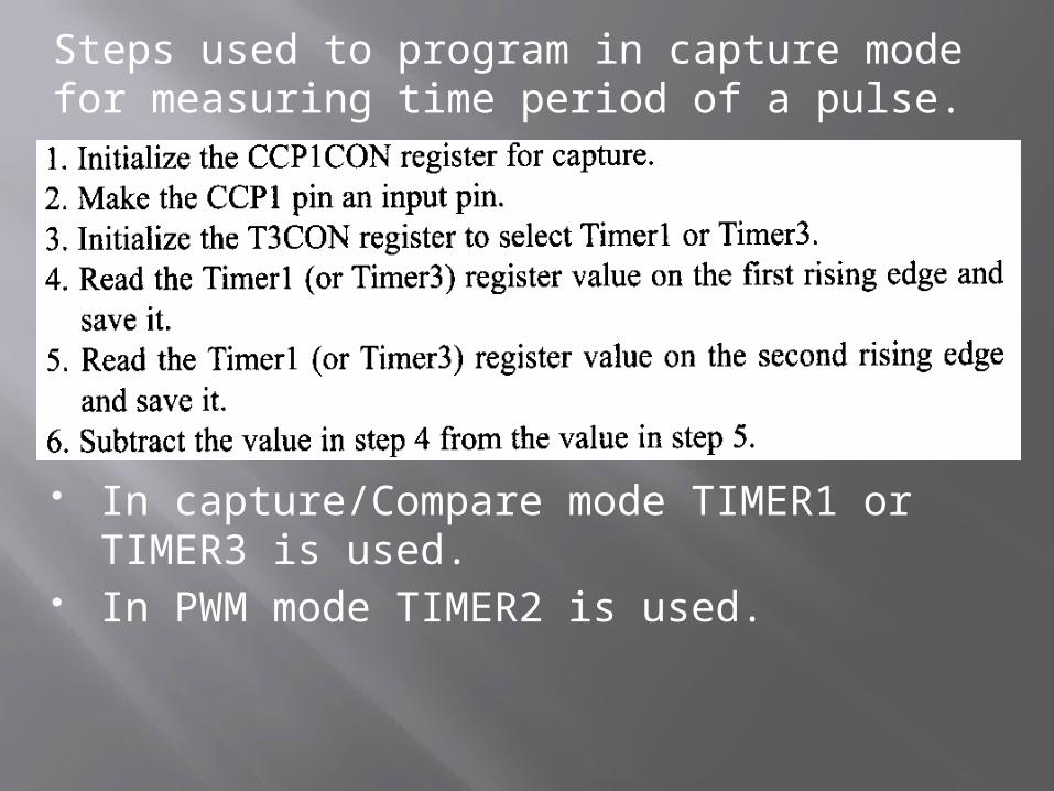
Steps used to program in capture mode for measuring time period of a pulse.
In capture/Compare mode TIMER1 or TIMER3 is used.
In PWM mode TIMER2 is used.
Let me explain the overall theory of how the circuit and microcontroller will work to achieve our goal of building an rpm counter. The IR circuit will output pulses whenever it is interrupted (this type of IR circuit is also known as a 'photo-interruptor' circuit).Electrically, the photo-interrupter is two independent parts - the IR LED, and the photo-transistor.
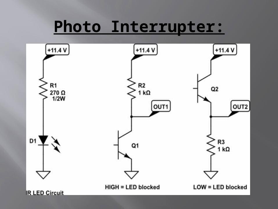
Photo Interrupter:
OUT1 will go LOW when the LED light is detected by IR sensor.
OUT2 will go HIGH when the LED light is detected by IR sensor.
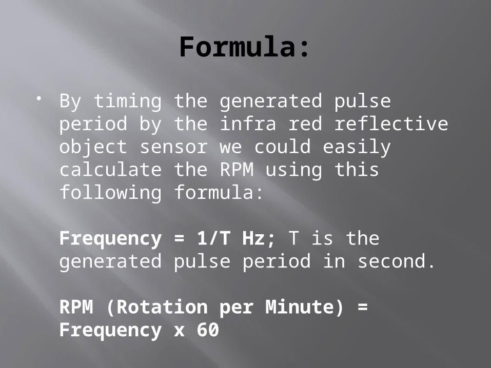
Formula: By timing the generated pulse period by
the infra red reflective object sensor we could easily calculate the RPM using this following formula:
Frequency = 1/T Hz; T is the generated pulse period in second.
RPM (Rotation per Minute) = Frequency x 60
Applications:
This circuit can be used to calculate speed of rotating wheels, discs and motor shafts.
This circuit can be used at places where direct contact with motor shafts or wheels is not possible to be made, as in case of vehicles and also in industrial machines.
This circuit can be used at homes to check speed of small battery operated fans and other motor based devices.
Limitations: The main limitation of this project is that
IR sensor for measuring the RPM need to be kept very close to the moving object.
Also the IR sensor used in this project have some limitations of maximum switching frequency. So we can measure RPMS with in that limitations.