Embed Size (px)
Citation preview
Lancer Parking Structure Conceptual Design
CLIENT: Mr. Steve Smith, CBU
TECHNICAL CONSULTANTS
Ms. Kristen Brown, Rick Engineering,
Mr. Don Marks, ipd-global,
Dr. Jong-Wha Bai, CBU-College of Engineering
-Alejandra Gastelum, -Danielle Lynch, -Manzi Dusabimana, -Suhail Farah
EGR 401
CAPSTONE DESIGN
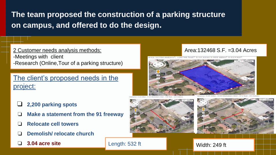
The team proposed the construction of a parking structure
on campus, and offered to do the design.
Width: 249 ft
Area:132468 S.F. =3.04 Acres 2 Customer needs analysis methods:
-Meetings with client
-Research (Online,Tour of a parking structure)
The client’s proposed needs in the
project:
❏ 2,200 parking spots
❏ Make a statement from the 91 freeway
❏ Relocate cell towers
❏ Demolish/ relocate church
❏ 3.04 acre site Length: 532 ft
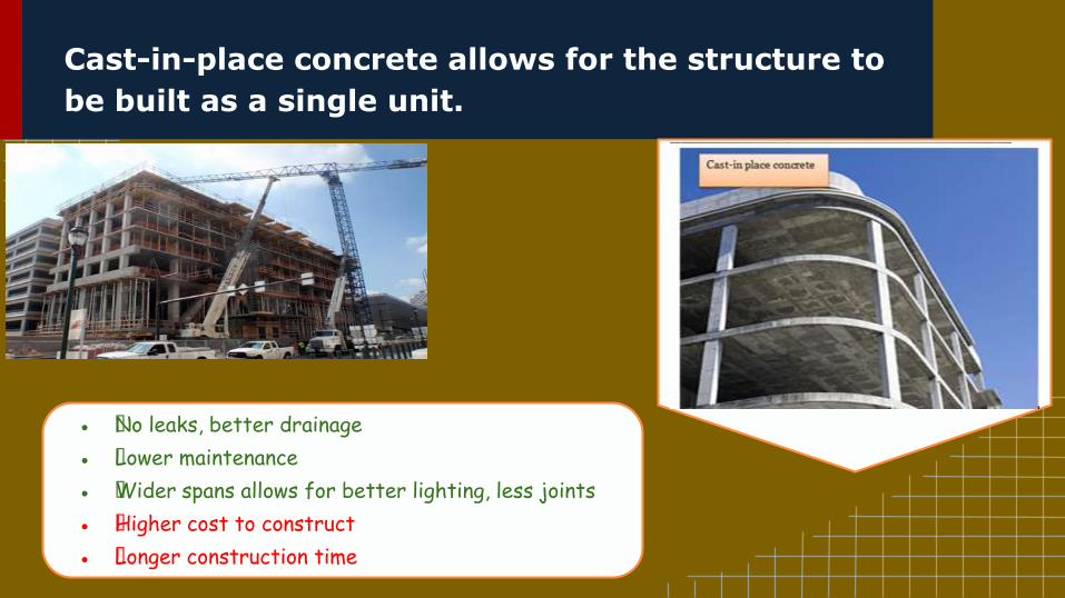
Cast-in-place concrete allows for the structure to
be built as a single unit.
● —No leaks, better drainage
● —Lower maintenance
● —Wider spans allows for better lighting, less joints
● —Higher cost to construct
● —Longer construction time
Comparison of Alternatives for construction
Materials.
Three selected alternatives for
the internal configuration...
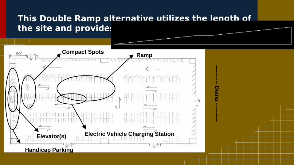
This Double Ramp alternative utilizes the length of the site and provides roughly 440 spots per level
Compact SpotsRamp
Elevator(s) Electric Vehicle Charging Station
Handicap Parking
----------D
ian
a ----------
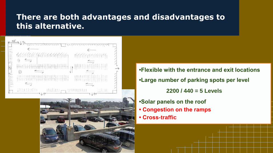
There are both advantages and disadvantages to this alternative.
•Flexible with the entrance and exit locations
•Large number of parking spots per level
2200 / 440 = 5 Levels
•Solar panels on the roof
• Congestion on the ramps
• Cross-traffic
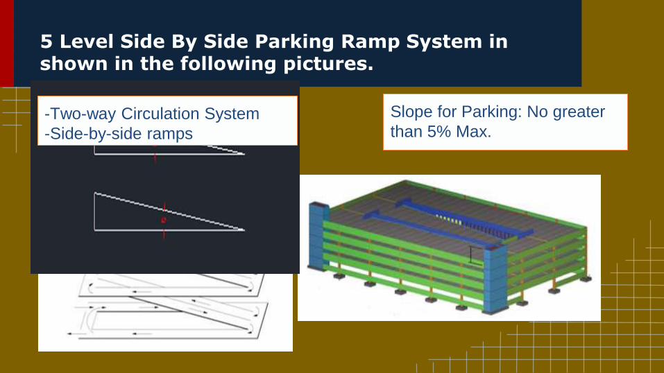
5 Level Side By Side Parking Ramp System in shown in the following pictures.
Slope for Parking: No greater
than 5% Max.-Two-way Circulation System
-Side-by-side ramps
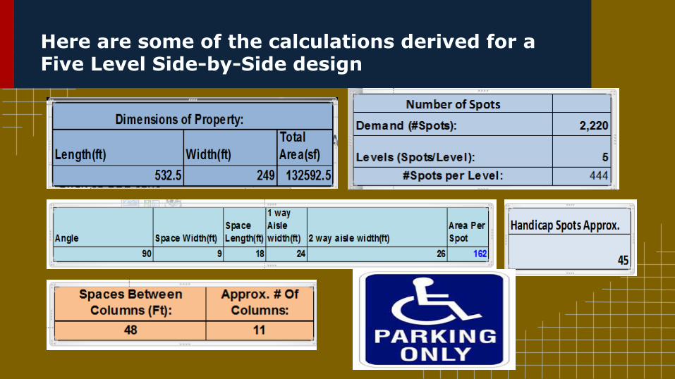
Here are some of the calculations derived for a Five Level Side-by-Side design
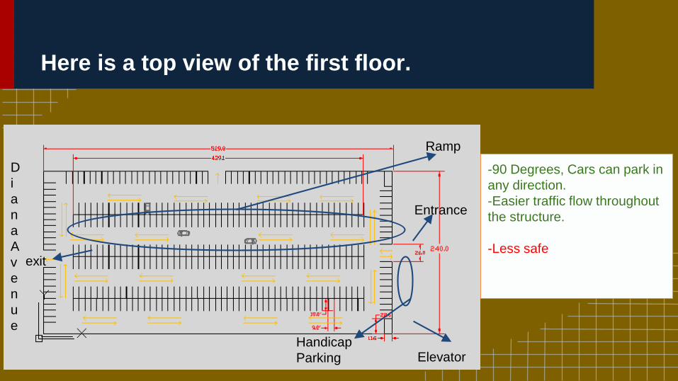
Here is a top view of the first floor.
Ramp
Elevator
exit
Entrance
-90 Degrees, Cars can park in
any direction.
-Easier traffic flow throughout
the structure.
-Less safe
Handicap
Parking
D
i
a
n
a
A
v
e
n
u
e
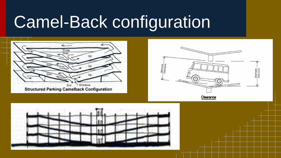
Camel-Back configuration
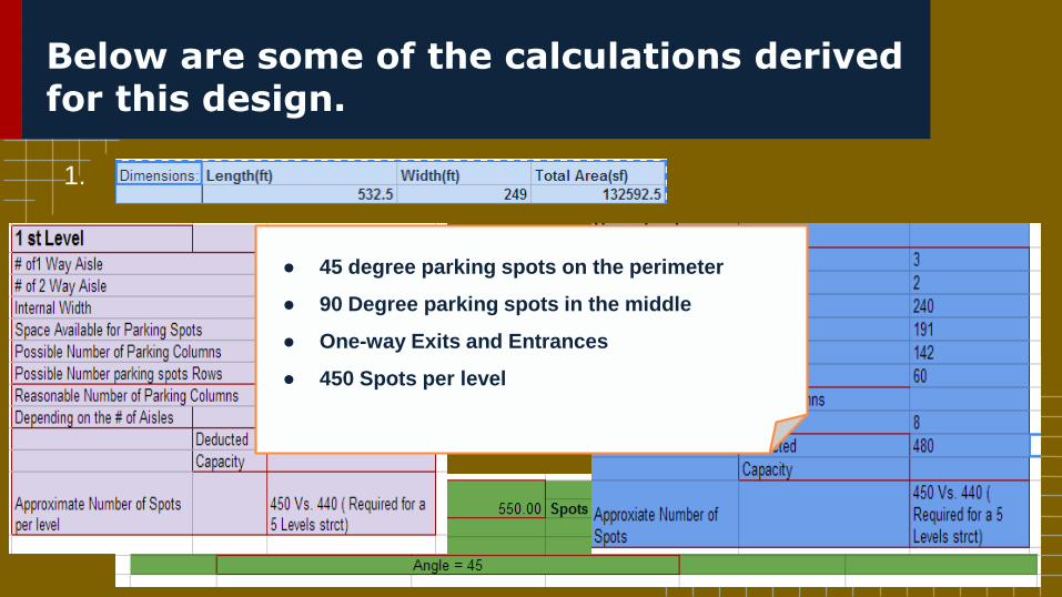
Below are some of the calculations derived for this design.
1.
2.
3.
4.
● 45 degree parking spots on the perimeter
● 90 Degree parking spots in the middle
● One-way Exits and Entrances
● 450 Spots per level
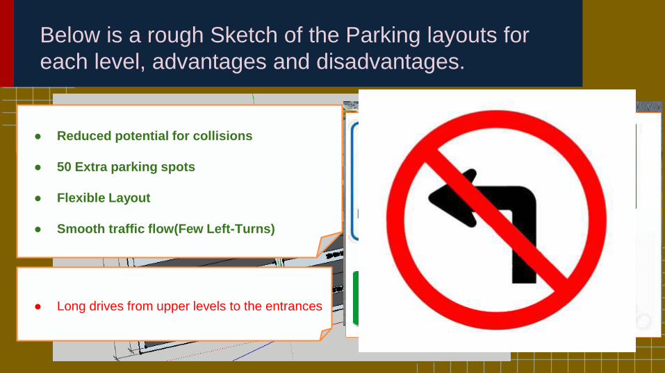
Below is a rough Sketch of the Parking layouts for
each level, advantages and disadvantages.
● Reduced potential for collisions
● 50 Extra parking spots
● Flexible Layout
● Smooth traffic flow(Few Left-Turns)
● Long drives from upper levels to the entrances
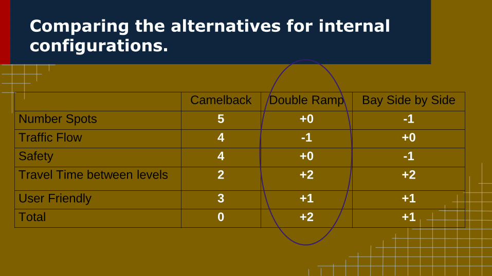
Comparing the alternatives for internal configurations.
Camelback Double Ramp Bay Side by Side
Number Spots 5 +0 -1
Traffic Flow 4 -1 +0
Safety 4 +0 -1
Travel Time between levels 2 +2 +2
User Friendly 3 +1 +1
Total 0 +2 +1
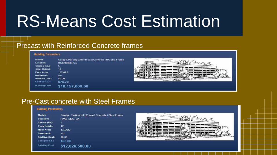
RS-Means Cost Estimation
Precast with Reinforced Concrete frames
Pre-Cast concrete with Steel Frames
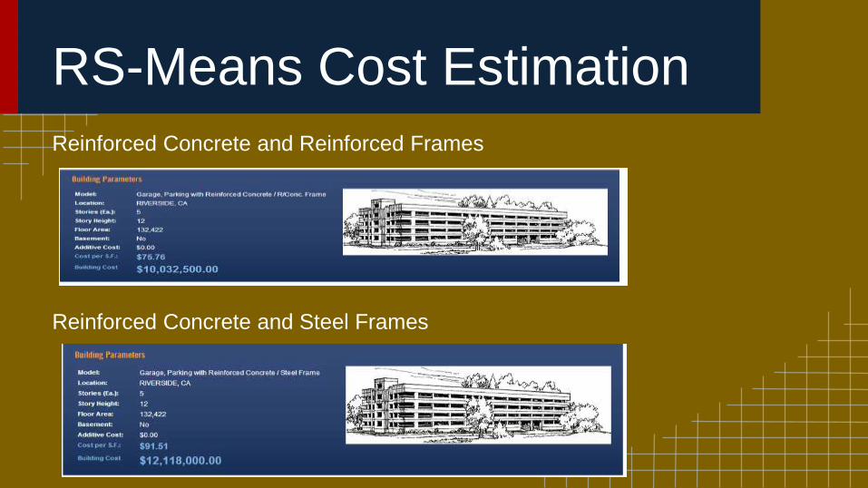
RS-Means Cost Estimation
Reinforced Concrete and Reinforced Frames
Reinforced Concrete and Steel Frames
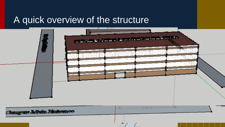
A quick overview of the structure

QUESTIONS?