Embed Size (px)
Citation preview
IJRET: International Journal of Research in Engineering and Technology eISSN: 2319-1163 | pISSN: 2321-7308
_______________________________________________________________________________________
Volume: 04 Issue: 08 | August-2015, Available @ http://www.ijret.org 213
INVESTIGATION AND OPTIMIZATION OF EDM PERFORMANCE MEASURES USING
EMPIRICAL DATA ANALYSIS
Kalyani S. Kanekar1, Diwesh B. Meshram
2
1Dept. of Mechanical Engg Dr. Babasaheb Ambedkar collage of Engg. And research Wanadongari (Nagpur),
Maharashtra, India.
[email protected] 2Dept. of Mechanical Engg Dr. Babasaheb Ambedkar collage of Engg. And research Wanadongari (Nagpur),
Maharashtra, India.
Abstract
In this paper research is aimed to investigate and optimization of EDM performance measures in order to find out best ideal EDM
electrode having higher material removal rate, improved surface finish and lower electrode wear rate. For this four EDM
electrodes of four different materials (viz. Gr, Cu, Br and Al) are developed by three different manufacturing methodologies.
Electrode design is very time consuming process and done interactively using CAD system. In this research work Vertical Milling
Machine, Net Shape Casting and Die Sinking EDM do EDM electrodes fabrication. After the electrode Fabrication testing of
electrodes is done on Die Sinking EDM. For optimization two different advanced methods of optimization SAW & TOPSIS are
used for analysis of EDM performance measures and to predict optimal choice of each EDM electrode. The analysis of both
optimization methods reveals Copper is best EDM electrode followed by Brass, Aluminium and Graphite. Experimental results
are provided to verify this approach.
Key Words: EDM, MRR, EWR, SR, OPTIMIZATION, SAW, TOPSIS
--------------------------------------------------------------------***----------------------------------------------------------------------
I. INTRODUCTION
EDM is one of the main non-conventional machining
process in which current is converted into heat. EDM is a
thermal process in which rapid and continuous spark is
discharged between electrically conductive workpiece and
electrode in dielectric medium such as kerosene [1]. Now a
day the advance materials viz. super alloys, ceramic &
composites have wide applications in industrial equipment’s
and aerospace industry due to their excellent properties like
high strength, high bending stiffness, low thermal
expansion, better fatigue characteristics. These advance
materials are used in aero engine components, automotive
ceramic gas turbine, nuclear reactors etc. Thus present
manufacturing industries facing challenges from these super
alloys as they are very hard and difficult to machining,
required high precision and surface quality which increase
machining cost. The solution to meet these requirements and
to survive in these challenges is use of EDM. EDM plays
excellent role in machining difficult to machine material and
complicated geometries with better surface finish and
dimensional accuracy which is impossible to achieve by
other conventional machining [2]. But EDM electrode
manufacturing is very time consuming and expensive
process. It have been observed that major cost and time for
manufacturing of electrode could occupy more than 50 % of
total machining cost [3]. Thus correct selection of
manufacturing condition is one of the most important
aspects to take into consideration during electrode
manufacturing. The aim is to produce and evaluate EDM
electrodes manufactured by various manufacturing
technologies. In this research electrodes are fabricated by
vertical milling machining (WMC), Net shape casting and
Die sinking EDM process. Vertical Milling Machine
(WMC) is a computer-controlled process and thus two main
electrodes (Cu & Gr) are manufactured by Vertical milling
machine operation. In WMC, system can be manually
programmed and accept files from CAD system. There for
first electrode is design in Unigraphics 9 software and this
CAD file is then used for making program for WMC
operation. Brass electrode is fabricated using Net Shape
Casting process. Net Shape Casting is a process in which
cast part is produced by forming mould from sand mixture
and then pouring molten metal into it. Copper electrode is
used for mould making in this process. Aluminium electrode
is directly manufactured by Die Sinking EDM process using
Graphite as a master tool manufactured by WMC process.
All electrodes are tested on Die sinking EDM machine using
same workpiece of 5mm thick MS sheet. To find out best
manufacturing technology comparison is takes place
between all three manufacturing methodologies on the basis
of Cost & time. Performance of EDM process is measured
with respect to the Material Removal Rate (MRR),
Electrode Wear Rate (EWR) and Surface Finish of
workpiece. Optimization is done under four criteria: MRR,
EWR, SR & Total Cost of electrode. The methods used for
Optimization are Simple Addictive Weighting (SAW) and
Technique for Order Preference by Similarities to an Ideal
Solution (TOPSIS) to find out best optimal solution of
electrode among all four electrodes.
IJRET: International Journal of Research in Engineering and Technology eISSN: 2319-1163 | pISSN: 2321-7308
_______________________________________________________________________________________
Volume: 04 Issue: 08 | August-2015, Available @ http://www.ijret.org 214
II. METHEDOLOGY
Fabrication of EDM electrode is very difficult and time-
consuming task. Considering the overall literature review
through research paper and market survey, it was observed
that most of problems are related to complex shape.
Methodology adopted for this research work is shown in
below figure.
Chart 1- Methodology
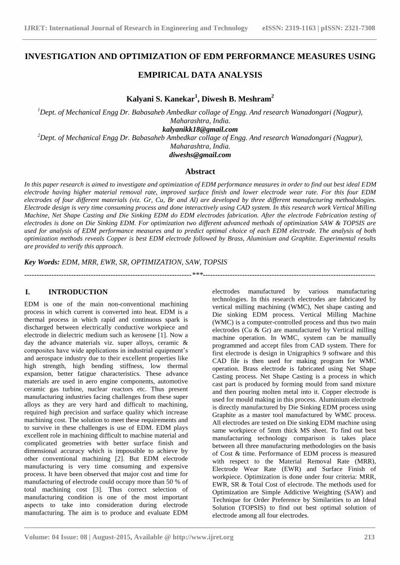
2.1. Modeling Of Electrode Design
Modeling of electrode is done in latest Unigraphics 9
software. But we have only jpg file of design, which is not
clear enough for solid modeling of the part. Thus first step is
to Re-design college logo into coral draw software. With the
Re-design model gives the clear & good appearance and
aesthetic to the design. Once the part is Re-Design into coral
draw software the coral draw file is directly imported to the
CAD-Model by using Auto-Cad software. This CAD-
Model is again imported into NX-Model by using latest
Unigraphics-9 software and complete solid modeling of part
is done in this software.
Figure 1 Solid Model of Electrode design in Unigraphics
software
2.2. Material Selection
Selection of material for EDM tool is one of the important
step in research. Owing to the increased development in
field of EDM, it is very important to select material having
higher material removal rate, lower electrode wear rate and
improved surface finish. For material selection number of
research papers are reviewed which shows Graphite,
Copper, Brass& Aluminium are best material for EDM
electrode [4], [5], [11]. On this basis following four material
are selected,
1. Graphite
2. Copper
3. Brass
4. Aluminium
III. EXPERIMENTAL PROCESS
This is the main step in research. The aim is to produce
EDM electrodes by different manufacturing methods and
compare the performance parameter of each electrode. After
fabrication of the EDM Electrode, finishing and testing is
done on Die-sinking EDM machine using constant
workpiece (5mm thick MS sheet). During testing of
electrode a hole is drilled on the topside of electrode for
fixing the electrode in holder.
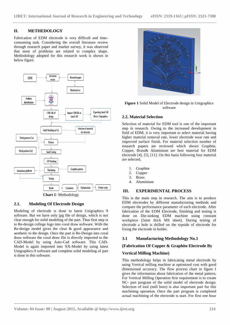
3.1 Manufacturing Methodology No.1
(Fabrication Of Copper & Graphite Electrode By
Vertical Milling Machine)
This methodology helps in fabricating metal electrode by
using Vertical milling machine at optimized cost with good
dimensional accuracy. The flow process chart in figure I
gives the information about fabrication of the metal pattern.
For Vertical Milling Operation first requirement is to create
NC- part program of the solid model of electrode design.
Selection of tool (mill bore) is also important part for this
machining operation. Once the part program is completed
actual machining of the electrode is start. For first one hour
IJRET: International Journal of Research in Engineering and Technology eISSN: 2319-1163 | pISSN: 2321-7308
_______________________________________________________________________________________
Volume: 04 Issue: 08 | August-2015, Available @ http://www.ijret.org 215
4 mm milling cutter is used to remove excessive material
from work part, then for next two hour 1.5 mm diameter
milling cutter is used and finally for critical portion of
electrode design 1 mm diameter milling cutter is used for
next three hours. So time required for machining of copper
and graphite electrode is 6 hours for each electrode. This
operation is done at Spindle speed = 3000 rpm, Feed rate
=1000 mm/min and Depth of cut = 0.2 mm. after electrode
fabrication testing is done at constant machining set up on
Die Sinking EDM. This testing is done on MS sheet of 5mm
thickness at I=15 A.
Figure 2. Finished Cu electrode
Figure 3. Tested MSBy Cu electrode
Figure 4 Finished Gr electrode
Figure 5 Tested MS Workpiece By Gr Electrode
3.2 Manufacturing Methodology No.2
(Net Shape Casting of Brass electrode)
Net shape casting is a process by which cast part produced
by forming a mould from a sand mixture and then pouring
molten liquid metal into the cavity in the mould. The
material used in this process was brass. For the net shape
casting first important requirement is pattern making. We
use copper electrode created by the WMC machining
process as a pattern for the net shape casting. Mould is
developed using copper tool as a pattern from a sand
mixture and then pouring molten liquid of brass material
into the cavity in the mould. The mould is then cooled until
the metal has solidified. At last, the casting is separated
from the mould. The next step was the finishing of the cast
electrode. This operation was performed on the Lathe. The
finishing process help in getting the surface flatness and
having removing burr from the electrode. The finish
Electrode has to be tested on the Die- Sinking EDM
machine. The workpiece and all the other parameters was
constant and same in the VMC machining operation
Figure 6 Finished Br Electrode
IJRET: International Journal of Research in Engineering and Technology eISSN: 2319-1163 | pISSN: 2321-7308
_______________________________________________________________________________________
Volume: 04 Issue: 08 | August-2015, Available @ http://www.ijret.org 216
Figure 7. Tested MS Workpiece By Br Electrode
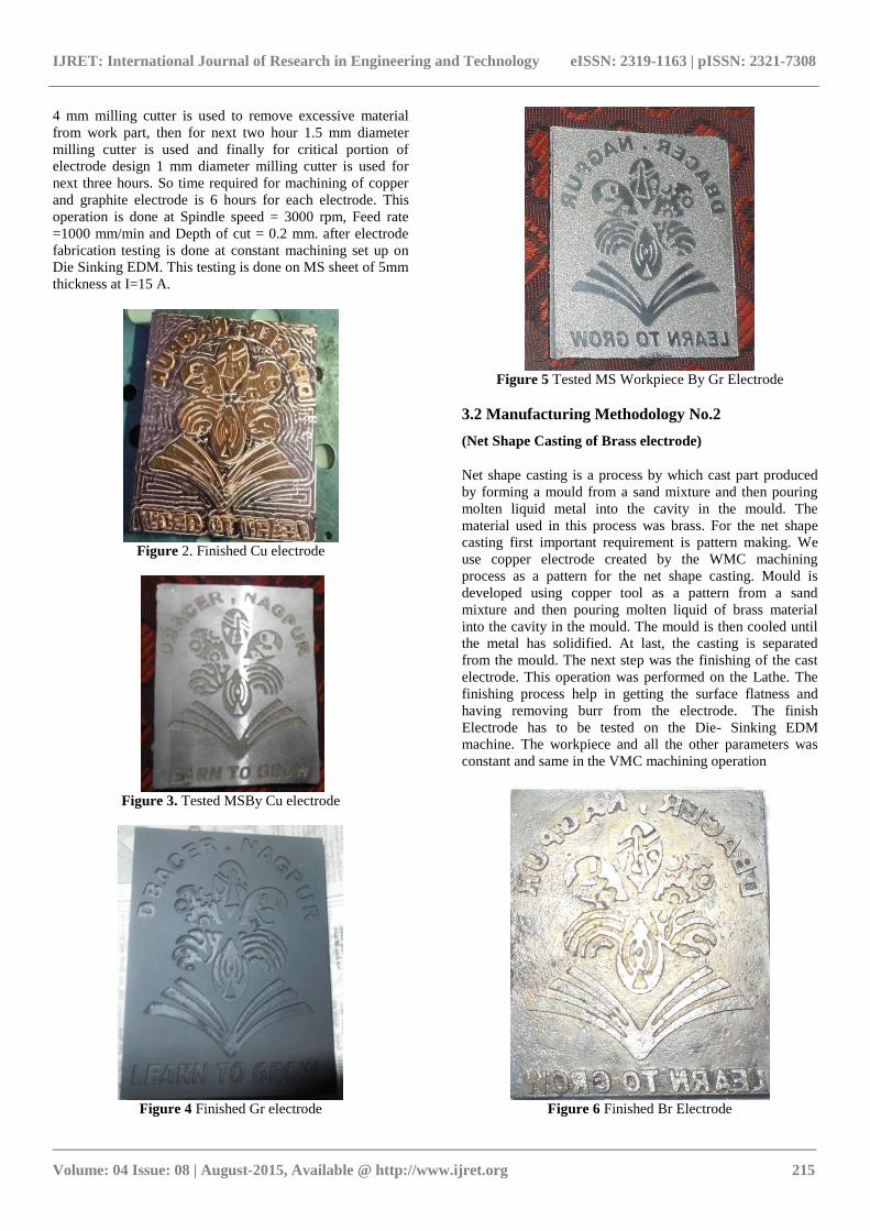
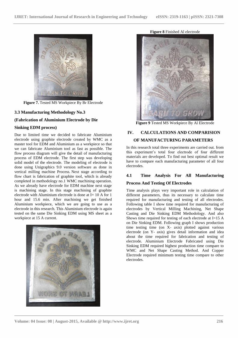
3.3 Manufacturing Methodology No.3
(Fabrication of Aluminium Electrode by Die
Sinking EDM process)
Due to limited time we decided to fabricate Aluminium
electrode using graphite electrode created by WMC as a
master tool for EDM and Aluminium as a workpiece so that
we can fabricate Aluminium tool as fast as possible. The
flow process diagram will give the detail of manufacturing
process of EDM electrode. The first step was developing
solid model of the electrode. The modeling of electrode is
done using Unigraphics 9.0 version software as done in
vertical milling machine Process. Next stage according to
flow chart is fabrication of graphite tool, which is already
completed in methodology no.1 WMC machining operation.
As we already have electrode for EDM machine next stage
is machining stage. In this stage machining of graphite
electrode with Aluminium electrode is done at I= 10 A for 1
hour and 15.6 min. After machining we get finished
Aluminium workpiece, which we are going to use as a
electrode in this research. This Aluminium electrode is again
tested on the same Die Sinking EDM using MS sheet as a
workpiece at 15 A current.
Figure 8 Finished Al electrode
Figure 9 Tested MS Workpiece By Al Electrode
IV. CALCULATIONS AND COMPARISION
OF MANUFACTURING PARAMETERS
In this research total three experiments are carried out. from
this experiment’s total four electrode of four different
materials are developed. To find out best optimal result we
have to compare each manufacturing parameter of all four
electrodes.
4.1 Time Analysis For All Manufacturing
Process And Testing Of Electrodes
Time analysis plays very important role in calculation of
different parameters, thus its necessary to calculate time
required for manufacturing and testing of all electrodes.
Following table I show time required for manufacturing of
electrodes by Vertical Milling Machining, Net Shape
Casting and Die Sinking EDM Methodology. And also
Shows time required for testing of each electrode at I=15 A
on Die Sinking EDM. Following graph I shows production
time testing time (on X- axis) plotted against various
electrode (on Y- axis) gives detail information and idea
about the time required for fabrication and testing of
electrode. Aluminium Electrode Fabricated using Die
Sinking EDM required highest production time compare to
WMC and Net Shape Casting Method. And Copper
Electrode required minimum testing time compare to other
electrodes.

IJRET: International Journal of Research in Engineering and Technology eISSN: 2319-1163 | pISSN: 2321-7308
_______________________________________________________________________________________
Volume: 04 Issue: 08 | August-2015, Available @ http://www.ijret.org 217
Table -1 Production Time And Testing Time For All
Electrodes.
Manufacturing
methodology
Electrode
Material
Total
Manufacturing
time
(Min)
Testing
time for
Electrode
WMC (Vertical
milling machine)
Graphite
390 60
WMC(Vertical
milling machine) Copper 390
30
Net shape casting Brass 130
40.8
Die sinking EDM Aluminium 76 42
0
50
100
150
200
250
300
350
400
Manufacturing
Time (min)
Testing Time(min)
Figure 10 Manufacturing Time & Testing Time Vs. All
Electrodes
4.2 Material Removal Rate (Mrr)
MRR is an important performance measure of EDM and
many researchers research on improving mechanism of
Materiel Removal in EDM. Mechanism of Material
Removal means conversion of electrical energy into heat
energy. It is also well known by many EDM researchers that
Material Removal Mechanism is the process of
transformation of material elements between tool and
workpiece. There for MRR of the work piece will be
measure by dividing the weight of workpiece before and
after machining against the machining time that was
achieved [6], [7].
The following table II contains detail information about
weight of electrode, time required for testing and
corresponding MRR of electrode. Graph II shows Copper
having highest MRR followed by Brass, Aluminium and
Graphite. MRR is plotted against all four electrodes.
Table 2. MRR of Electrodes
Electrode
Material
Weight of
Electrode
(gms)
Total
machining
Time
(min)
MRR=
(gms/min)
Graphite
Copper
229
662
60
30
3.8167
22.067
Brass
586 40.8 14.3627
Aluminium 329 42 7.833
0
5
10
15
20
25
MRR
MRR
Figure 11 MRR Vs All Electrodes
4.3 Electrode Wear Rate (Ewr)
Proper knowledge of electrode wear is essential for
determining the electrode size and number of electrodes.
Electrode wear is a function of factor such as polarity,
thermal conductivity, and melting point of electrode,
duration and intensity of spark discharge [11]. Table III
show EWR of all electrodes and Graph III shows EWR
plotted against corresponding Electrodes. Copper electrode
shows lowest EWR compare to other electrodes.
The EWR is measured by
EWR=
IJRET: International Journal of Research in Engineering and Technology eISSN: 2319-1163 | pISSN: 2321-7308
_______________________________________________________________________________________
Volume: 04 Issue: 08 | August-2015, Available @ http://www.ijret.org 218
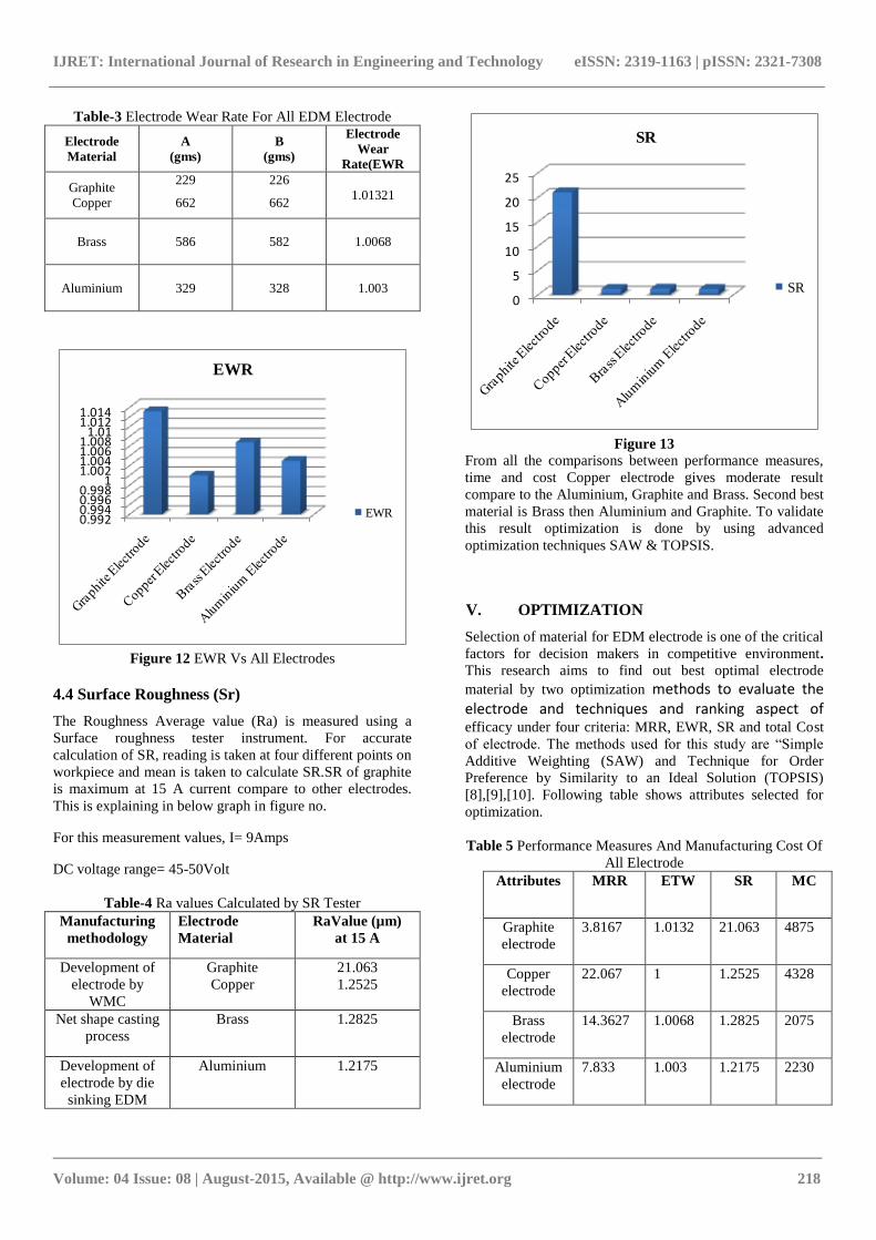
Table-3 Electrode Wear Rate For All EDM Electrode
Electrode
Material
A
(gms)
B
(gms)
Electrode
Wear
Rate(EWR
Graphite
Copper
229
662
226
662 1.01321
Brass
586 582 1.0068
Aluminium 329 328
1.003
0.9920.9940.9960.998
11.0021.0041.0061.008
1.011.0121.014
EWR
EWR
Figure 12 EWR Vs All Electrodes
4.4 Surface Roughness (Sr)
The Roughness Average value (Ra) is measured using a
Surface roughness tester instrument. For accurate
calculation of SR, reading is taken at four different points on
workpiece and mean is taken to calculate SR.SR of graphite
is maximum at 15 A current compare to other electrodes.
This is explaining in below graph in figure no.
For this measurement values, I= 9Amps
DC voltage range= 45-50Volt
Table-4 Ra values Calculated by SR Tester
Manufacturing
methodology
Electrode
Material
RaValue (µm)
at 15 A
Development of
electrode by
WMC
Graphite
Copper
21.063
1.2525
Net shape casting
process
Brass 1.2825
Development of
electrode by die
sinking EDM
Aluminium 1.2175
0
5
10
15
20
25
SR
SR
Figure 13
From all the comparisons between performance measures,
time and cost Copper electrode gives moderate result
compare to the Aluminium, Graphite and Brass. Second best
material is Brass then Aluminium and Graphite. To validate
this result optimization is done by using advanced
optimization techniques SAW & TOPSIS.
V. OPTIMIZATION
Selection of material for EDM electrode is one of the critical
factors for decision makers in competitive environment.
This research aims to find out best optimal electrode
material by two optimization methods to evaluate the electrode and techniques and ranking aspect of efficacy under four criteria: MRR, EWR, SR and total Cost
of electrode. The methods used for this study are “Simple
Additive Weighting (SAW) and Technique for Order
Preference by Similarity to an Ideal Solution (TOPSIS)
[8],[9],[10]. Following table shows attributes selected for
optimization.
Table 5 Performance Measures And Manufacturing Cost Of
All Electrode
Attributes MRR ETW SR MC
Graphite
electrode
3.8167 1.0132 21.063 4875
Copper
electrode
22.067 1 1.2525 4328
Brass
electrode
14.3627 1.0068 1.2825 2075
Aluminium
electrode
7.833 1.003 1.2175 2230
IJRET: International Journal of Research in Engineering and Technology eISSN: 2319-1163 | pISSN: 2321-7308
_______________________________________________________________________________________
Volume: 04 Issue: 08 | August-2015, Available @ http://www.ijret.org 219
Here, MRR- material removal rate
EWR- electrode wear rate
SR- surface roughness
MC- manufacturing cost for electrode
5.1 Topsis Method:-
Step 1:-Construction of normalized Matrix
This step transforms various attribute dimensions into non-
dimensional attributes, by using the eq. (1). To calculate the
normalizing decision matrix, squaring each element of the
matrix of alternatives. Then, sum the squaring elements in
each column. After that, calculate the root for the sum in
each column. Divide the elements in alternatives matrix of
each column by the root in each column and the resulted
normalized matrix stated in table7.2.
rij= ……………… (1)
let’s calculate Σ (Xij)2first for ease of calculation.
MRR =
=27.7337
EWR=
= 2.0115
SR=
= 21.1741
MC =
= 7195.5356
Now, normalized matrix can be calculated as,
rij =
Table 6 Normalized Matrix
Attributes MRR EWR SR MC
Graphite
electrode
0.1376 0.5037 0.9947 0.6775
Copper
electrode 0.7956 0.4971 0.0591 0.6014
Brass
electrode
0.5178 0.5005 0.0605 0.2883
Aluminium
electrode
0.2824 0.4986 0.0574 0.3099
Step 2:- calculation of weight Relative importance matrix
MRR EWR SR MC
MRR 1 2 3 1
EWR 0.5 1 4 2
SR 0.33 0.25 1 0.5
MC 1 0.5 2 1
Now,
MRR =(1x2 x3x1)1/4
=1.5650
EWR = (0.5x1 x4x2)1/4
=1.3195
SR = (0.33 x 0.25 x 1 x 0.5)1/4
= 0.5285
MC = (1 x 0.5 x 2 x 1)1/4
= 1
MRR + EWR + SR + MC = 1.5650+1.3195+0.5285+1
= 4.413
Weight( Wj): -
MRR = = 0.3546
SR = = 0.2990
EWR = = 0.1197
MC = = 0.2266
Σ MRR + EWR + SR + MC = 0.9999
≈ 1
Now, we have to check consistency of weights
[A1] = Relative importance matrix
0.3546
Wj= 0.2990
0.1197
0.2266
IJRET: International Journal of Research in Engineering and Technology eISSN: 2319-1163 | pISSN: 2321-7308
_______________________________________________________________________________________
Volume: 04 Issue: 08 | August-2015, Available @ http://www.ijret.org 220
[A3] = [A1][A2]
1 2 3 1 0.3546
= 0.5 1 4 2 0.2990
0.33 0.25 1 0.5 0.1197
1 0.5 2 1 0.2266
A4] =
4.3381
4.7100
[A4] = 3.5480
4.2811
Now,
λmax =
=4.2193
C.I.= ………………………..(2)
C.I.= = =0.0731
CR= = = 0.0821 < 0.1
Since CR = 0.1 or < 0.1 is considered as acceptable, our weights
are consistence.
Here,
CR= Consistency ratio
RI= Random index value
CI= Consistency ratio
Step 3:-Construct the weighted normalized decision matrix by
using below eq. In this step Multiply each column of the normalized
decision matrix by its associated weight.
Vij = Wj x Tij
MRR EWR SR MC
MRR 0.0487 0.1506 0.119 0.1531
EWR 0.2821 0.1138 0.007 0.1359
SR 0.1836 0.1496 0.0072 0.0651
MC 0.1001 0.149 0.0068 0.0700
Step 4:-Determine the ideal and negative ideal solutions.
Ideal solution is calculated by using the eq. (3). It is
the maximum of performance and safety and
minimum in cost. Negative ideal solution is calculated by
using the eq. (4) and it is reverse to the Ideal solution.
The ideal and negative ideal solution are presented in
table no. 7.
A* = {Vj*, _ _ _ _,Vn*} …………………………….(3)
Where,
Vj = { max (Vij) if j j; min i (Vij) if j j`}
A` = {Vj*, _ _ _ _, Vn*} ……………………………. (4)
Where,
Vj = {min (Vij) if j j; max (Vij) if j j`}
From above equations, calculated positive and negative ideal
solution are given in following table 7
Table 7 Calculated Positive And Negative Ideal Solutions
Positive ideal solution Negative ideal solution
MRR 0.282 0.0487
EWR 0.1138 0.1506
SR 0.119 0.0068
MC 0.0651 0.1531
Calculations of separation measures using Euclidian formula
Si += …………………………..(5)
IJRET: International Journal of Research in Engineering and Technology eISSN: 2319-1163 | pISSN: 2321-7308
_______________________________________________________________________________________
Volume: 04 Issue: 08 | August-2015, Available @ http://www.ijret.org 221
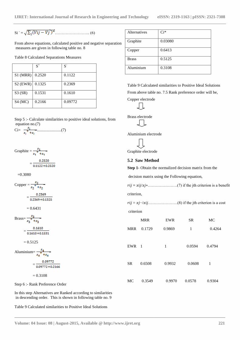
Si - = …………………….. (6)
From above equations, calculated positive and negative separation
measures are given in following table no. 8
Table 8 Calculated Separations Measures
S+ S
-
S1 (MRR) 0.2520 0.1122
S2 (EWR) 0.1325 0.2369
S3 (SR) 0.1531 0.1610
S4 (MC) 0.2166 0.09772
Step 5 :- Calculate similarities to positive ideal solutions, from
equation no.(7)
Ci= ........................(7)
Graphite =
=
=0.3080
Copper =
=
= 0.6431
Brass=
=
= 0.5125
Aluminium=
=
= 0.3108
Step 6 :- Rank Preference Order
In this step Alternatives are Ranked according to similarities
in descending order. This is shown in following table no. 9
Table 9 Calculated similarities to Positive Ideal Solutions
Alternatives Ci*
Graphite 0.03080
Copper 0.6413
Brass 0.5125
Aluminium 0.3108
Table 9 Calculated similarities to Positive Ideal Solutions
From above table no. 7.5 Rank preference order will be,
Copper electrode
Brass electrode
Aluminium electrode
Graphite electrode
5.2 Saw Method
Step 1- Obtain the normalized decision matrix from the
decision matrix using the Following equation,
𝑟𝑖𝑗 = 𝑥𝑖𝑗/𝑥𝑗∗………………….(7) if the jth criterion is a benefit
criterion,
𝑟𝑖𝑗 = 𝑥𝑗−/𝑥𝑖𝑗………………….(8) if the jth criterion is a cost
criterion
MRR EWR SR MC
MRR 0.1729 0.9869 1 0.4264
EWR 1 1 0.0594 0.4794
SR 0.6508 0.9932 0.0608 1
MC 0.3549 0.9970 0.0578 0.9304
IJRET: International Journal of Research in Engineering and Technology eISSN: 2319-1163 | pISSN: 2321-7308
_______________________________________________________________________________________
Volume: 04 Issue: 08 | August-2015, Available @ http://www.ijret.org 222
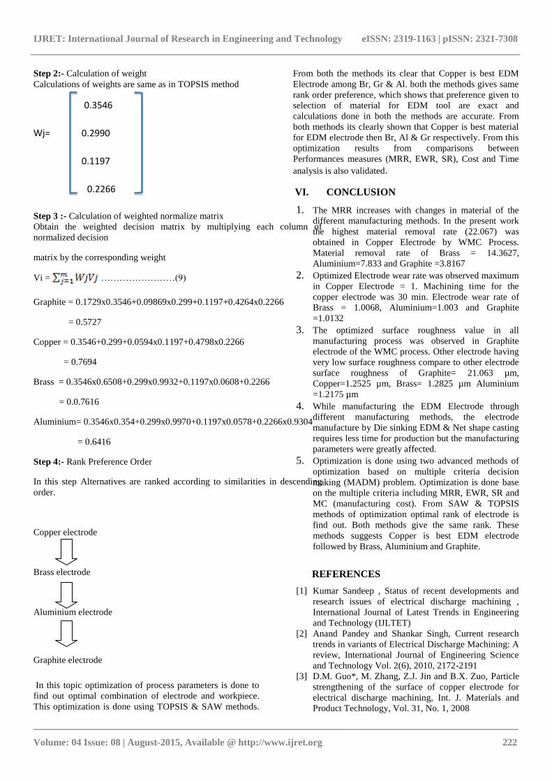
Step 2:- Calculation of weight
Calculations of weights are same as in TOPSIS method
0.3546
Wj= 0.2990
0.1197
0.2266
Step 3 :- Calculation of weighted normalize matrix
Obtain the weighted decision matrix by multiplying each column of
normalized decision
matrix by the corresponding weight
Vi = ……………………(9)
Graphite = 0.1729x0.3546+0.09869x0.299+0.1197+0.4264x0.2266
= 0.5727
Copper = 0.3546+0.299+0.0594x0.1197+0.4798x0.2266
= 0.7694
Brass = 0.3546x0.6508+0.299x0.9932+0.1197x0.0608+0.2266
= 0.0.7616
Aluminium= 0.3546x0.354+0.299x0.9970+0.1197x0.0578+0.2266x0.9304
= 0.6416
Step 4:- Rank Preference Order
In this step Alternatives are ranked according to similarities in descending
order.
Copper electrode
Brass electrode
Aluminium electrode
Graphite electrode
In this topic optimization of process parameters is done to
find out optimal combination of electrode and workpiece.
This optimization is done using TOPSIS & SAW methods.
From both the methods its clear that Copper is best EDM
Electrode among Br, Gr & Al. both the methods gives same
rank order preference, which shows that preference given to
selection of material for EDM tool are exact and
calculations done in both the methods are accurate. From
both methods its clearly shown that Copper is best material
for EDM electrode then Br, Al & Gr respectively. From this
optimization results from comparisons between
Performances measures (MRR, EWR, SR), Cost and Time
analysis is also validated.
VI. CONCLUSION
1. The MRR increases with changes in material of the
different manufacturing methods. In the present work
the highest material removal rate (22.067) was
obtained in Copper Electrode by WMC Process.
Material removal rate of Brass = 14.3627,
Aluminium=7.833 and Graphite =3.8167
2. Optimized Electrode wear rate was observed maximum
in Copper Electrode = 1. Machining time for the
copper electrode was 30 min. Electrode wear rate of
Brass = 1.0068, Aluminium=1.003 and Graphite
=1.0132
3. The optimized surface roughness value in all
manufacturing process was observed in Graphite
electrode of the WMC process. Other electrode having
very low surface roughness compare to other electrode
surface roughness of Graphite= 21.063 µm,
Copper=1.2525 µm, Brass= 1.2825 µm Aluminium
=1.2175 µm
4. While manufacturing the EDM Electrode through
different manufacturing methods, the electrode
manufacture by Die sinking EDM & Net shape casting
requires less time for production but the manufacturing
parameters were greatly affected.
5. Optimization is done using two advanced methods of
optimization based on multiple criteria decision
making (MADM) problem. Optimization is done base
on the multiple criteria including MRR, EWR, SR and
MC (manufacturing cost). From SAW & TOPSIS
methods of optimization optimal rank of electrode is
find out. Both methods give the same rank. These
methods suggests Copper is best EDM electrode
followed by Brass, Aluminium and Graphite.
REFERENCES
[1] Kumar Sandeep , Status of recent developments and
research issues of electrical discharge machining ,
International Journal of Latest Trends in Engineering
and Technology (IJLTET)
[2] Anand Pandey and Shankar Singh, Current research
trends in variants of Electrical Discharge Machining: A
review, International Journal of Engineering Science
and Technology Vol. 2(6), 2010, 2172-2191
[3] D.M. Guo*, M. Zhang, Z.J. Jin and B.X. Zuo, Particle
strengthening of the surface of copper electrode for
electrical discharge machining, Int. J. Materials and
Product Technology, Vol. 31, No. 1, 2008
IJRET: International Journal of Research in Engineering and Technology eISSN: 2319-1163 | pISSN: 2321-7308
_______________________________________________________________________________________
Volume: 04 Issue: 08 | August-2015, Available @ http://www.ijret.org 223
[4] K.S.BankeR, A.D. Oza and R.B. Dave, Performance
Capabilities of EDM machining using Aluminum,
Brass and Copper for AISI 304L Material,
International Journal of Application or Innovation in
Engineering & Management (IJAIEM), Volume 2,
Issue 8, August 2013
[5] Roger Kern, Sinker electrode material selection, EDM
Today, July/ August 2008 issue
[6] Kumar Sandeep , Review Paper Current Research
Trends in Electrical Discharge Machining: A Review ,
Research Journal of Engineering Sciences , 2278 –
9472 Vol. 2(2), 56-60, February (2013)
[7] Kuldeep Ojha, R. K. Garg, K. K. Sing, MRR
Improvement in Sinking Electrical Discharge
Machining: A Review, Journal of Minerals &
Materials Characterization & Engineering, Vol. 9,
No.8, pp.709-739, 2010
[8] Ruta simanaviciene and LionasUstinovichius,
Sensitivity Analysis for Quantitnive Dicisio Making
Methods : SAW & TOPSIS
[9] Seyed Mohammad HosseinHojjati and AlirezaAnvary,
An Integrated SAW, TOPSIS Method for Ranking the
Major Lean Practices Based on Four Attributes , World
Applied Sciences Journal 28 (11): 1862-1871, 2013
ISSN 1818-4952
[10] Mohammed F. Aly, Hazem A. Attia and Ayman M.
Mohammed, Integrated Fuzzy (GMM) -TOPSIS
Model for Best Design Concept and Material Selection
Process, International Journal of Innovative Research
in Science, Engineering and Technology, Vol. 2, Issue
11, November 2013