Embed Size (px)
Citation preview

DRILLING PRODUCTS & SERVICES

CONTENTS
INTRODUCTION
About Grant Prideco Drilling Products & Services ........................................................iv
Vision and Values, Ethics ...........................................................................................v
Quality, Health, Safety and Environment (QHS&E) .......................................................vi
API Certifications
ISO Certifications
Inspection Procedures and Traceability .....................................................................vii
Locations .............................................................................................................. viii
Disclaimer and Trademarks ........................................................................................x
DRILL PIPE
Drill Pipe Design and Manufacturing ....................................................................... 1-2
Grant Prideco Proprietary Drill Pipe Grades ..............................................................1-9
Grant Prideco High-Strength Grades
Grant Prideco Sour Service Grades
Grant Prideco eXtreme® Reach (XR™) Drill Pipe ....................................................... 1-12
ROTARY-SHOULDERED CONNECTIONS
Rotary-Shouldered Connection Selection Guide ........................................................ 2-2
TurboTorque™ (TT™) and TurboTorque-M™ (TT-M™) Connections .................................2-5
eXtreme® Torque (XT®) and eXtreme® Torque-M™ (XT-M™) Connections ..................... 2-14
Grant Prideco Double Shoulder™ (GPDS™) Connections ............................................ 2-19
HI-TORQUE® (HT™) Connections .............................................................................. 2-21
Drill Collar (DC™) Connections ............................................................................... 2-24
SST® and SRT® Connections ................................................................................... 2-27
API and Public Domain Connections ....................................................................... 2-28
Grant Prideco Benchmark ..................................................................................... 2-36
Xmark™ Benchmark ............................................................................................. 2-37
Care and Handling of Grant Prideco Drill Pipe ......................................................... 2-38
HARDBANDING
Platinum® HB Hardbanding ..................................................................................... 3-2
SmoothX™ Hardbanding .........................................................................................3-4
SmoothEdge® Tool Joints ........................................................................................3-5
About NOV Grant Prideco ..........................................................................V

www.GrantPrideco.com
CUSTOM-ENGINEERED PRODUCTS (CEP)
CEP Capabilities ..................................................................................................... 4-1
Slip-Proof® Drill Pipe ..............................................................................................4-3
Landing Strings .................................................................................................... 4-4
Completion Drill Pipe .............................................................................................4-5
Intervention Risers ............................................................................................... 4-6
HEAV YWEIGHT DRILL PIPE (HWDP)
Standard HWDP .....................................................................................................5-2
Tri-Spiral™ HWDP ...................................................................................................5-4
Spiral-Wate® HWDP ............................................................................................... 5-6
HWDP Features and Options ....................................................................................5-8
HWDP Grades .........................................................................................................5-9
DRILL COLLARS & DRILL STEM ACCESSORIES
Slick Drill Collars .................................................................................................... 6-1
Spiral Drill Collars .................................................................................................. 6-1
Pony Collars ..........................................................................................................6-2
Slip and Elevator Recesses ......................................................................................6-3
Material Grades .................................................................................................... 6-4
Pup Joints .............................................................................................................6-9
Subs ................................................................................................................... 6-10
Rotary Kellys ....................................................................................................... 6-12
Thread Protectors ................................................................................................ 6-13
Lift Subs and Lift Plugs ......................................................................................... 6-13
Features and Options ........................................................................................... 6-14
Care and Maintenance .......................................................................................... 6-16
THE INTELLISERV® NETWORK
The IntelliServ Network Components ....................................................................... 7-2
Features and Benefits ............................................................................................7-4
SERVICE & SUPPORT
Technical Support ..................................................................................................8-2
Field Support ........................................................................................................8-3
Internal Plastic Coating ......................................................................................... 8-4
Tool Joint Break-In Services (Make and Break) ......................................................... 8-4
Licensed Repair and Accessory Network ...................................................................8-5
Training and Seminars .......................................................................................... 8-6
CONTENTS
THTHE E INTELLLLISERV® NETWORK
The e InntetelliServv Network Components ................................... ........................... .................... 7-2
Featturu eses aandn Benenefits ..................................................... ......... ...............................................7-4

ABOUT GRANT PRIDECO DRILLING PRODUCTS & SERVICES
Grant Prideco Drilling Products & Services is the world’s
largest supplier of drill pipe and drill stem accessories. The
division manufactures, sells and services a full range of
proprietary and American Petroleum Institute (API) drill pipe, drill
collars, heavyweight drill pipe, kellys, subs, pup joints and other
drill stem accessories. Product quality and performance are
optimized by Grant Prideco’s unique vertical integration from mill
to market, which helps to mitigate the potentially adverse effects
of tight steel mill supplies and the associated rising costs of
production and raw materials.
Grant Prideco’s IntelliServ® Network, the industry’s first high-
speed, real-time drill string telemetry system is a breakthrough
technology that transforms the drill string into an advanced
information tool to enable instantaneous bi-directional
communication from the rig floor to the drill bit. With The
IntelliServ Network, engineers and geologists have access to critical
information at speeds up to one million bits per second. Commands
from the surface or between downhole devices can be sent,
received and acted upon in real time to radically improve monitor-
ing and measurement of all vital data during downhole operations.
From the top-drive to the bit sub, whether manufacturing products
to efficiently drill the simplest well, products for drilling in the
harshest environments or that enable the drilling of world record
wells, Grant Prideco Drilling Products & Services is the single source
for all drill stem needs. Through innovative products, worldwide
operations, expert engineering and design resources, sophisticated
laboratories and a global repair network, Grant Prideco meets the
demands of any tough drilling challenge.
iiv
ABOUT NOV GRANT PRIDECO
OV Grant Prideco is the world’s N

0
2
4
6
8
20072001 2002 2003 2004 2005 2006
TRIR LTIR
8.4
4.1
4.7
3.1
4.2
2.5
1.5
0.6
2.0
1.0
2.7
1.2
3.0
1.4
2008
1.4
0.5
0
2
4
6
20072001 2002 2003 2004 2005 2006
TRIR LTIR
6.4
4.2
5.0
2.2
3.5
1.5 1.4
0.5
2008
1.3
0.4
1.9
0.8
2.1
0.8
2.3
0.7
Quality, Health, Safety and Environment (QHS&E) Policy The long-term business success of Grant Prideco depends on the
Company’s ability to continuously improve products and services,
while protecting its people and the environments in which they
work and live. This commitment is in the best interest of our
employees and stockholders.
QHS&E is the responsibility of all
employees, with the active commit- ment and support of
management. Grant Prideco will facilitate this policy through the
QHS&E Management System with the following objectives:
services that consistently meet the needs and expectations
of our customers
contractors
live by pollution prevention, waste minimization, wise use of
natural resources and continual improvement
public on the safe and environmentally responsible use of our
products and services
Grant Prideco is committed to the proactive integration of QHS&E
objectives into management systems at all levels. The commit-
ments in this policy are in addition to a basic obligation to comply
with Grant Prideco standards, as well as all applicable laws and
regulations where the Company operates. Compliance with this
pledge is critical in order to reduce risks and add value to Grant
Prideco’s products and services.
ABOUT GRANT PRIDECO DRILLING PRODUCTS & SERVICES
GRANT PRIDECO GLOBAL INCIDENT TRENDYTD – February 2008
DRILLING PRODUCTS & SERVICESINCIDENT TREND
YTD – February 2008
T R I R R e d u c t i o n - 8 0 %
LT I R R e d u c t i o n - 9 0 %
T R I R R e d u c t i o n - 8 3 %
LT I R R e d u c t i o n - 8 8 %
vi
Grant Prideco is committed to safety from the board room to the shop floor. While increasing production over 11% in 2007, Grant Prideco Drilling Products and Services reduced total recordable incidents by 83% and lost time recordable incidents by 85%.
ABOUT NOV GRANT PRIDECO

www.GrantPrideco.com
API and ISO CertificationsWhere applicable, all Grant Prideco products meet or exceed the
requirements and are manufactured in compliance with the latest
edition of the following API standards:
In addition, where applicable, all Grant Prideco Drilling Products &
Services manufacturing locations comply with the current
requirements of the following:
Quality, Inspection Procedures and TraceabilityQuality is the primary objective in every phase of Grant Prideco’s
operations. The Quality Program is a dynamic one in which
personnel at all levels strive toward customer satisfaction,
continuous improvement and elimination of
non-conformance.
Along with the day-to-day task of ensuring that
standards are met, the Company continually
refines its own internal standards. Manufactur-
ing engineers are devoted to improving Grant
Prideco’s process capabilities through:
The resulting efficiency and economy mean optimum product
performance and cost savings to customers.
Additionally, Grant Prideco licenses repair facilities located
throughout the world. To ensure that the highest possible perfor-
mance and quality are maintained, a full-time audit department
continuously communicates with licensees and provides support
and manufacturing technology.
Rigid Inspection Procedures
of its products at each critical phase of the procurement and
manufacturing process. Internal specifications that meet or exceed
applicable API standards assure compliance of all products. All
inspection results are recorded, maintained and made available
for customer review.
Traceability
All product material and process traceability are maintained from
receipt of mill-certified raw material to
completion of manufacturing. Products
are assigned serial numbers, and
inspection and traceability records are
made available for customer review.
7-02475D-00515CT-0403
omply with the curre
vii
ABOUT GRANT PRIDECO DRILLING PRODUCTS & SERVICESABOUT NOV GRANT PRIDECO

LOCATIONS
Grant Prideco, Inc
U.S.A.P H O N E : 2 8 1- 8 7 8 - 8 0 0 0T O L L F R E E : 8 6 6 - 47 2 - 6 8 61
Sales Offices
U . S . A .Grant PridecoDrilling Products & Services, and The IntelliServ® Network
C A N A D AGrant Prideco Canada
C H I N A Grant Prideco (Jiangsu) Drilling
Golden TowerChaoyang District
E-mail: [email protected]
E U R O P E A N D A F R I C A Grant PridecoSuite C
Aberdeen, Scotland
Email: [email protected]
F A R E A S T, A S I A - PA C I F I C , I N D I A
E-mail: [email protected]
M E X I C OGrant Prideco de Mexico, SA de CV
Col. Anzures
GrantPrideco.com
M I D D L E E A S TGrant PridecoDubai Airport Free Zone
DubaiUnited Arab Emirates
R U S S I A , F S UGrant Prideco
Email: [email protected]
Manufacturing Facilities
U . S . A .
The IntelliServ Network
www.IntelliServ.netEmail: [email protected]
viii
A S T, A S I A - PA C I F I C ,
Orideco de Mexico, SA de CV
zures
ideco.com
L E E A S Tridecoirport Free Zone
Arab Emirates
Manufacturing Facilities
U . S . A .
4
4
4
NOV Grant Prideco
NOV Grant PridecoDrilling Products & Services400 N. Sam Houston Parkway E.Suite 900Houston, TX 77060U.S.A.Phone: 281-878-8000Fax: 281-878-5736Toll Free: 866-472-6861

www.GrantPrideco.com
M A N U F A C T U R I N G L O C AT I O N S
S A L E S A N D S E R V I C E L O C AT I O N S
A U S T R I AVoest Alpine Tubulars GmbH. & Co KGAlpinestrasse
Kindberg-Aumuhl Austria
C H I N A Grant Prideco (Jiangsu) Drilling
Zhangmu Town, Jiangyan CityJiangsu Province
Email: [email protected]; [email protected]
Grant Prideco Tianjin
District TianjinTianjin
I N D O N E S I A
Kabil Industrial Estate
I TA LY
ix
M E X I C OGrant Prideco De Mexico, S.A. de C.V.
Mexico-Veracruz Cd.
Pagliai Veracruz
Mexico
LOCATIONS
M A N U F A C T U R I N G L O C AT I O N S
S A L E S A N D S E R V I C E L O C AT I O N S
A U S T R I AVoest Alpine Tubulars GmbH. & Co KGAlpinestrasse
C H I N A Grant Prideco (Jiangsu) Drilling
Zhangmu Town, Jiangyan City
I N D O N E S I A
Kabil Industrial Estate
M E X I C OGrant Prideco De Mexico, S.A. de C.V.
Mexico-Veracruz Cd.

†While every effort has been made to insure the accuracy of the tables herein, this material is presented as a reference guide only. The technical information contained herein should not be construed as a recommendation. Grant Prideco cannot assume responsibility for the results obtained through the use of this material. No expressed or implied warranty is intended.
Grant Prideco is the world leader in drill stem and drill pipe technology, manufacturing, sales and service; a global leader in drill bit
technology and manufacturing, specialized downhole tools and related applications and services; and a leading provider of large-bore,
engineered connectors. The Company provides a variety of product and service solutions to onshore and offshore markets worldwide.
Find out more about Grant Prideco’s global activities at www.GrantPrideco.com.
Grant Prideco Drilling Products & Services Trademarks
x
Grant Prideco (full logo) ®
Grant Prideco®
Grant Prideco Double
®
HT®
IntelliPipe®
IntelliServ®
Platinum®
Slip-Proof®
SmoothEdge®
Spiral-Wate®
SST®
Tuff-Weld®
TuffWeld®
Other Trademarks
API (logo) ® is a trademark of the American Petroleum Institute.
DNV (logo) ® is a trademark of Det Norske Veritas.
NanoSteel is a trademark of the NanoSteel Company.
Teflon® is a trademark of DuPont.
Truscope® is a trademark of Tuboscope.
Weco® is a trademark of FMC Technologies.
DISCLAIMER AND TRADEMARKS

DR
ILL PIP
E
DRILL PIPE

DR
ILL
PIP
E DRILL PIPE

1-1www.GrantPrideco.com
Grant Prideco provides the industry with the three most
important considerations for drill pipe: quality, technology
and economy. Manufacturing processes are vertically
integrated from raw material to finished product. Pipe is supplied
by the Company’s own mill and tool joints are forged in its own
facilities.
Drilling Products & Services also offers all the features of a fully
integrated service company. Beyond full technical and field support
for its products, Grant Prideco provides an array of other services,
including training and seminars, tool joint break-in prior to delivery
and a worldwide repair and accessory manufacturing network.
DRILL PIPE

1-2
DRILL PIPE
Drill Pipe Design and Manufacturing
Design
Drill pipe life is extended by creating a design that is inherently
fatigue resistant. When drill pipe rotates in a bent condition,
alternating tensile and compressive stresses can cause fatigue
cracks that may ultimately result in drill pipe “washouts” and
failure. Stresses tend to concentrate in areas where geometries
change rapidly. The shorter or more irregular the transition, the
higher the stress concentration. Alternately, the longer and
smoother the transition, the lower the stress.
The thick weldneck, required for adequate weld strength and the short internal upset of a standard industry design concentrates stress in the adjacent pipe body.
The weldneck/upset design incorporates a counterbored weldneck, an extended internal upset length, a shallow internal taper angle and generous radii to produce the optimum stress-reducing geometry.
Grant Prideco Weldneck / Upset Design
PipeBody
Tool Joint
Weldneck
Upset
Internal Upset Taper
WeldLine
Tool Joint ID
WeldneckWall
Thickness
Internal Upset Taper Angle
Counter-bored
Weldneck
Tool Joint
Weldneck
Upset
Pipe Body
Pipe BodyWall
Thickness
Internal Upset Taper
WeldLine
Tool Joint ID & Weldneck/
Upset Are The Same
WeldneckWall
Thickness
Internal Upset Taper Angle
Generic Weldneck / Upset Design
Pipe BodyWall
Thickness

1-3www.GrantPrideco.com
Tool Joint OD Recut Tool Joint Torque Shoulder
Tool Joint IDRecut Tool Joint Pin Critical Section
New Tool Joint Pin Critical Section
DRILL PIPE
Geometry
The critical section of a joint of drill pipe is the transition from the
pipe body to the tool joint. This section consists of the weld that
joins the pipe and tool joint, and the transition from the thin
cross-section of the pipe to the thick cross-section of the tool joint.
The challenge to the drill pipe designer is to ensure that the weld is
stronger than the pipe body and the transition between the pipe
body and the tool joint is as seamless as possible.
Grant Prideco’s weldneck/upset design was engineered to
maximize fatigue resistance in this critical transition. A geometry
that minimizes stress concentrations is employed. The assembly is
configured to optimize the transition from the cross-section of the
pipe to the tool joint. The length of the internal upset is extended,
producing a shallow fade-away angle that blends into the pipe
body’s inside diameter with a liberal radius. To further improve
fatigue resistance, the surface finish of the assembly adjacent to
the weld line is improved by grinding on both the inside and
outside diameter.
The enhanced hardenability of Grant Prideco’s specially engineered tool joint steel produces more uniform microstructure and mechanical properties throughout the entire cross-section in comparison with standard 4137H steel.
The increased hardenability of Grant Prideco’s proprietary tool joint material provides more consistent mechanical properties through the tool joint sections, such as the critical section at the last engaged thread, especially on recut joints.
SAE/AISI4137H
Grant PridecoTool Joint Material
4 8 12 16 24 32
60
55
50
45
40
35
30
Distance From Quenched End (1/16 in)
Har
dnes
s (H
RC)
New Tool Joint Torque Shoulder
HARDENABILITY CURVE TOOL JOINT MATERIAL
Proprietary Steel
Grant Prideco incorporates specially designed proprietary steel for
both the drill pipe tube and the tool joint. Tube and billets are
produced by Grant Prideco mills in Austria and China or obtained
from qualified suppliers, and thoroughly inspected upon receipt to
verify that all material requirements are met. By closely matching
the chemistries of the tube and tool joint materials, Grant Prideco
ensures good weld compatibility and weld strength. Stringent
cleanliness requirements for both materials enhance fracture
toughness. The increased hardenability of the materials consis-
tently produces more uniform mechanical properties throughout
the entire cross-section, commanding adequate strength in the
weld zone and the critical sections of the connection. The result is
a more reliable product. For both API drill pipe and high-perfor-
mance, severe-environment products, Grant Prideco engineers
materials that increase product performance and integrity.

1-4
DRILL PIPE
Cut intoBillets
Preheat Forge Into ToolJoint Blank
Cut tolength
Bar orTubing
Tool JointBlank
QualityInspection
Finishing &Threading 5-step
PhosphateCoating
FinishedTool Joints
QualityInspection
QualityInspection
LaboratoryInspection
Inspection PointOptionalTool Joint
Break In
OptionalHardbanding
Legend
Round Cornered Square
Austenitizingwith Integrated
Oil Quench
Tempering
FurnaceBlanking & Boring
Grant Prideco Drill Pipe Manufacturing Process

1-5www.GrantPrideco.com
DRILL PIPE
Green Tube
Induction HeatingUpsetting
the PipeDeburringand Facing
AustenitizingFurnace
TemperingFurnaceH2O External Quench
QualityCheck
Straightening
Turn & BorePipe Tube Ready
to Weld
Tool Joint & Tube JoinedWith Inertia or Friction
Welder
Machining &Cleaning theWeld Zone
Austenitizingby Induction
Heating
W eld ZoneInspection
et Magnetic
Temperingby Induction
Heating
QuenchingInternal/External
Stress Relieve
Inspection includingEnd Area
Completed Drill Pipe
TUFF WELD® PROCESS
Full Length Pipe
1-6
DRILL PIPE
Tube Processing
Grant Prideco drill pipe is manufactured with state-of-the-art
production equipment. Tube ends are forged on modern Ajax
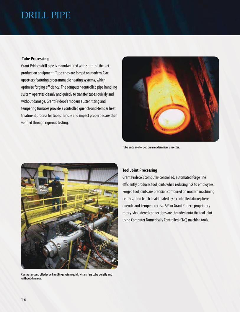
upsetters featuring programmable heating systems, which
optimize forging efficiency. The computer-controlled pipe handling
system operates cleanly and quietly to transfer tubes quickly and
without damage. Grant Prideco’s modern austenitizing and
tempering furnaces provide a controlled quench-and-temper heat
treatment process for tubes. Tensile and impact properties are then
verified through rigorous testing.
Tool Joint Processing
Grant Prideco’s computer-controlled, automated forge line
efficiently produces tool joints while reducing risk to employees.
Forged tool joints are precision contoured on modern machining
centers, then batch heat-treated by a controlled atmosphere
quench-and-temper process. API or Grant Prideco proprietary
rotary-shouldered connections are threaded onto the tool joint
using Computer Numerically Controlled (CNC) machine tools.
Tube ends are forged on a modern Ajax upsetter.
Computer controlled pipe handling system quickly transfers tube quietly and without damage.

1-7www.GrantPrideco.com
DRILL PIPE
Welding
A friction or inertia weld process joins tubes and tool joints. Both
processes are highly reliable and cost-effective, and produce
consistent and uniform weld zone properties. In terms of weld
quality, reliability, strength or metallurgical effects, both processes
produce a high-integrity, solid-state weld connection between the
tool joint and the drill pipe tube. The principles of both welding
processes are based on the rotation of one surface against another
at a relatively high speed and under heavy pressure. The friction
between the tool joint surface and the tube surface causes the
contact to heat up below the melting temperature at which they
are forged together, producing the weld.
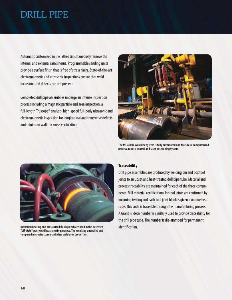
Grant Prideco’s latest MTI400VX weld line system is fully auto-
mated and features a computerized process and data system.
Robotic handling and laser control position systems provide
efficient operation and assure precise alignment between the tool
joint and tube. Subsequently, the weld’s heat-affected zone (HAZ)
receives the patented Tuff-Weld® process.
Tuff-Weld is a post-weld quenched and tempered heat treatment
of the heat-affected zone. The weld zone is heated by induction
to the specified austenitizing temperature, which is followed by
quenching from precisely positioned fluid nozzles. To ensure that
complete tempering is obtained, an area wider than the HAZ is
reheated to the proper tempering temperature by the induction
coil. A full 100% of welds that undergo the Tuff-Weld process are
subjected to hardness testing. The benefits of the Tuff-Weld
process are shown to the right by comparing the two weld zone
photomicrographs.
This photomicrograph depicts a typical normalized and tempered weld zone. The weld line is clearly evident by the contrasting microstructures of the tool joint and the tube upset. The microstructure of the higher carbon tool joint contains predominantly ferrite and pearlite, while the upset is often pearlite and has lower transitional constituents.
This photomicrograph depicts the typical microstructure of a Tuff-Weld® weld zone. The similar microstructures of the tool joint and the tube upset make the weld line difficult to detect. Both display tempered martensitic microstructures. The result is yield strengths and Charpy impact values superior to those of normalized microstructures. The Tuff-Weld process consistently produces stronger, tougher and more uniform weld zone properties. This combination of strength and toughness enhances fatigue resistance, making the Tuff-Weld process the most desired post-weld heat treatment in the industry. More than 50% of the drill pipe in the world is produced using the Tuff-Weld process.
1-8
DRILL PIPE
Automatic customized inline lathes simultaneously remove the
internal and external ram’s horns. Programmable sanding units
provide a surface finish that is free of stress risers. State-of-the-art
electromagnetic and ultrasonic inspections ensure that weld
inclusions and defects are not present.
Completed drill pipe assemblies undergo an intense inspection
process including a magnetic particle end area inspection, a
full-length Truscope® analysis, high-speed full-body ultrasonic and
electromagnetic inspection for longitudinal and transverse defects
and minimum wall thickness verification.
Induction heating and pressurized fluid quench are used in the patented Tuff-Weld® post-weld heat-treating process. The resulting quenched and tempered microstructure maximizes weld area properties.
Traceability
Drill pipe assemblies are produced by welding pin and box tool
joints to an upset and heat-treated drill pipe tube. Material and
process traceability are maintained for each of the three compo-
nents. Mill material certifications for tool joints are confirmed by
incoming testing and each tool joint blank is given a unique heat
code. This code is traceable through the manufacturing process.
A Grant Prideco number is similarly used to provide traceability for
the drill pipe tube. The number is die-stamped for permanent
identification.
The MTI400VX weld line system is fully automated and features a computerized process, robotic control and laser positioning system.

1-9www.GrantPrideco.com
DRILL PIPE
eXtreme® Drilling V-150™ Grade Drill Pipe
V-150 is a proprietary drill pipe grade offered by Grant Prideco for
applications that require ultra-high strength material. V-150
incorporates proprietary chemistry and a rigidly controlled
quench-and-temper heat treatment. The increased yield strength
provides superior torsional and tensile strength and enhanced
internal and collapse pressure integrity.
TSS™ Tough Sour Service 95 and 105 Grade Drill Pipe
TSS™-95 and TSS™-105 drill pipe are proprietary grades offered
by Grant Prideco for service in H2S environments. With a unique
chemistry and a specialized quenched and tempered heat treat-
ment, TSS-95 and TSS-105 have optimum fracture toughness,
controlled yield strength and restricted hardness. The tubes are
NACE Method A tested to a threshold stress of 85% and 70%
respectively of the Specified Minimum Yield Strength (SMYS).
TSS-95 and TSS-105 have API tool joints and are best suited for
environments having lower H2S concentrations. Because its
minimum fracture toughness is 100 ft-lbs, TSS-95 drill pipe is ideal
for more demanding drilling applications, such as those with high
bending loads and corrosive environments.
Grant Prideco Proprietary Drill Pipe Grades
In addition to all API grades, Grant Prideco produces drill pipe in
several proprietary grades including high-toughness, high-strength
and sour-service grades designed for the most challenging
applications in the most severe environments.
S-135T™ Enhanced Toughness 135 Grade Drill Pipe
S-135T™ drill pipe is a proprietary grade offered by Grant Prideco
for applications that require high strength and high toughness.
S-135T drill pipe incorporates a proprietary chemistry and a rigidly
controlled quenched and tempered heat treatment. The minimum
average specified Charpy impact energy is 59 ft-lbs for a 3/4 size
specimen at -4ºF, a 48% increase in impact energy over the
standard API S-135 grade. The performance behavior resulting from
this increase in toughness provides a margin of safety superior to
normal high-strength materials.
eXtreme® Drilling Z-140™ Grade Drill Pipe
Z-140™ is a proprietary drill pipe grade offered by Grant Prideco,
which is designed specifically for extreme drilling conditions
present in high temperature high pressure (HTHP) environments,
extended reach drilling (ERD), deepwater and ultra-deep wells.
Through proprietary steel chemistry and a rigidly controlled
quench-and-temper process, Z-140 drill pipe provides an excep-
tional balance between elevated strength and low-temperature
high-toughness requirements. Compared to standard API S-135
grade drill pipe, Grant Prideco’s Z-140 drill pipe grade provides a
higher minimum yield strength, a smaller window between
allowable minimum and maximum yield strength values and
increased toughness requirements to perform under the most
demanding cyclic loading operations.
The 5 inch 19.50 lb V-150™ drill pipe provides an 11% increase over S-135 in comparison to all standard API S-135 drill pipe in both tensile and torsional strength.
S-135 V -150™ %Improvement
Torsional Strength (ft-lbs) 74,100 82,300 11
Tensile Strength (lbs) 712,100 791,200 11
EXAMPLE: 5 IN 19.50 LB S-135 VS. V-150™

1-10
DRILL PIPE
eXtreme® Drilling CYX™ Grade Sour Service Drill Pipe
Grant Prideco’s three standard proprietary sour service grades are
suitable for most situations. However, customized sour service pipe
can be produced to meet specific customer requirements including
any combination of tube and tool joint yield strength and NACE
testing.
The following naming methodology is used for proper
identification of CYX.
CYX™ 000X-111Y where:
Examples of popular CYX combinations are included in the
accompanying grade table.
SS Grade Sour Service Drill Pipe
SS-95 and SS-105 are sour service drill pipe grades of high yield
strength, which meet the requirements of Canada’s IRP specifica-
tion for service in H2S environments. SS drill pipe features a unique
chemical composition and a controlled quench-and-temper heat
treatment that produces optimum fracture toughness, controlled
yield strength and restricted hardness for both tubes and tool
joints. SS tubes are NACE Method A tested to a threshold stress of
85% of the SMYS, and tool joints are NACE Method A tested to a
threshold stress of 65% of the SMYS .
eXtreme® Drilling XD® Grade Sour Service Drill Pipe
XD®-95 and XD®-105 are proprietary sour service drill pipe grades of
high yield strength offered by Grant Prideco for service in H2S
environments. XD drill pipe features a unique chemical composition
and a controlled quench-and-temper heat treatment that produces
optimum fracture toughness, controlled yield strength and
restricted hardness for both tubes and tool joints. XD tubes are
NACE Method A tested to a threshold stress of 70% of the SMYS.
XD drill pipe is resistant to sulfide stress cracking and offers
optimum resistance to fatigue-induced crack initiation and crack
propagation.
eXtreme® Drilling CXD™ Grade Sour Service Drill Pipe
CXD™-95 and CXD™-105 are identical to XD including material and
heat-treat process. For situations requiring quicker delivery, NACE
testing is omitted.
NACE Method A test apparatus
1-11www.GrantPrideco.com
DRILL PIPE
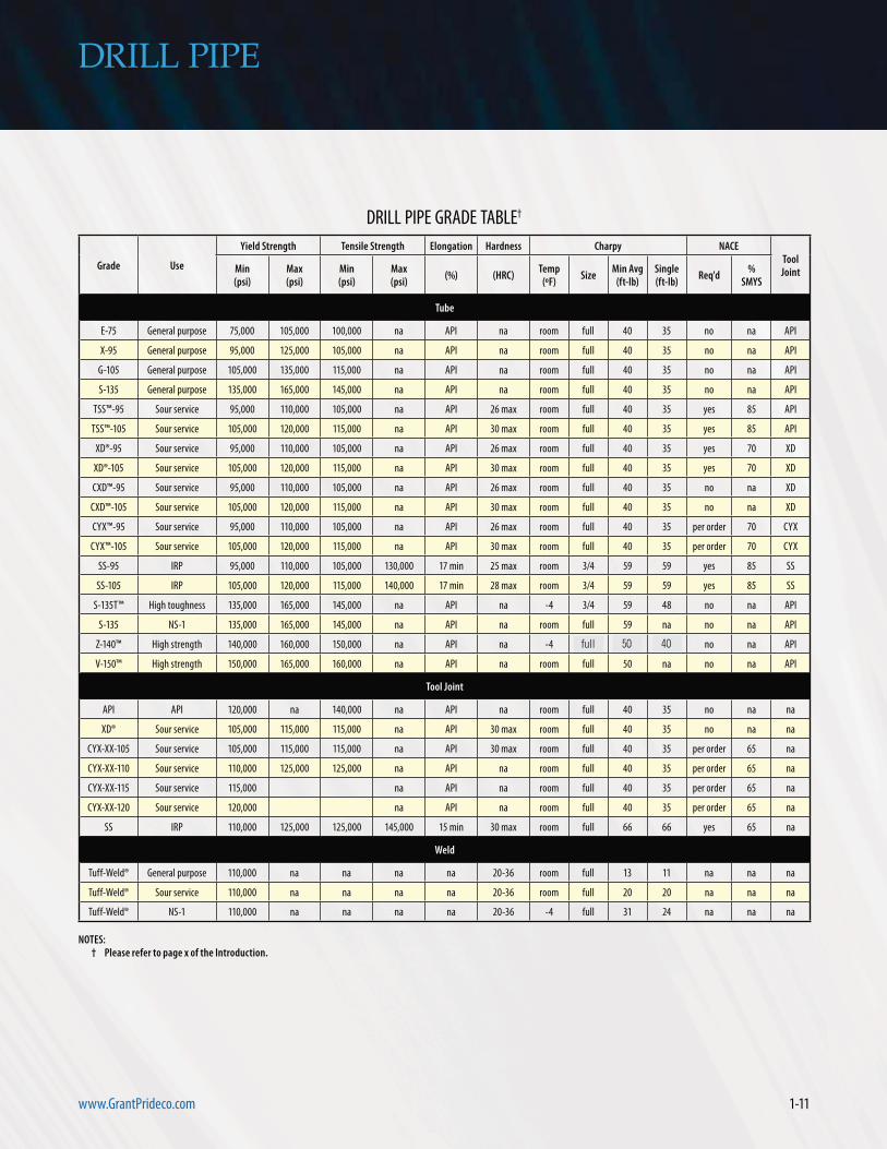
Grade Use
Yield Strength Tensile Strength Elongation Hardness Charpy NACETool JointMin
(psi)Max(psi)
Min(psi)
Max(psi)
(%) (HRC)Temp
(ºF)Size
Min Avg(ft-lb)
Single(ft-lb)
Req'd%
SMYS
Tube
E-75 General purpose 75,000 105,000 100,000 na API na room full 40 35 no na API
X-95 General purpose 95,000 125,000 105,000 na API na room full 40 35 no na API
G-105 General purpose 105,000 135,000 115,000 na API na room full 40 35 no na API
S-135 General purpose 135,000 165,000 145,000 na API na room full 40 35 no na API
TSS™-95 Sour service 95,000 110,000 105,000 na API 26 max room full 40 35 yes 85 API
TSS™-105 Sour service 105,000 120,000 115,000 na API 30 max room full 40 35 yes 85 API
XD®-95 Sour service 95,000 110,000 105,000 na API 26 max room full 40 35 yes 70 XD
XD®-105 Sour service 105,000 120,000 115,000 na API 30 max room full 40 35 yes 70 XD
CXD™-95 Sour service 95,000 110,000 105,000 na API 26 max room full 40 35 no na XD
CXD™-105 Sour service 105,000 120,000 115,000 na API 30 max room full 40 35 no na XD
CYX™-95 Sour service 95,000 110,000 105,000 na API 26 max room full 40 35 per order 70 CYX
CYX™-105 Sour service 105,000 120,000 115,000 na API 30 max room full 40 35 per order 70 CYX
SS-95 IRP 95,000 110,000 105,000 130,000 17 min 25 max room 3/4 59 59 yes 85 SS
SS-105 IRP 105,000 120,000 115,000 140,000 17 min 28 max room 3/4 59 59 yes 85 SS
S-135T™ High toughness 135,000 165,000 145,000 na API na -4 3/4 59 48 no na API
S-135 NS-1 135,000 165,000 145,000 na API na room full 59 na no na API
Z-140™ High strength 140,000 160,000 150,000 na API na -4 3/4 59 48 no na API
V-150™ High strength 150,000 165,000 160,000 na API na room full 50 na no na API
Tool Joint
API API 120,000 na 140,000 na API na room full 40 35 no na na
XD® Sour service 105,000 115,000 115,000 na API 30 max room full 40 35 no na na
CYX-XX-105 Sour service 105,000 115,000 115,000 na API 30 max room full 40 35 per order 65 na
CYX-XX-110 Sour service 110,000 125,000 125,000 na API na room full 40 35 per order 65 na
CYX-XX-115 Sour service 115,000 na API na room full 40 35 per order 65 na
CYX-XX-120 Sour service 120,000 na API na room full 40 35 per order 65 na
SS IRP 110,000 125,000 125,000 145,000 15 min 30 max room full 66 66 yes 65 na
Weld
Tuff-Weld® General purpose 110,000 na na na na 20-36 room full 13 11 na na na
Tuff-Weld® Sour service 110,000 na na na na 20-36 room full 20 20 na na na
Tuff-Weld® NS-1 110,000 na na na na 20-36 -4 full 31 24 na na na
DRILL PIPE GRADE TABLE†
NOTES: † Please refer to page x of the Introduction.
full 50 40

1-12
DRILL PIPE
5-7/8 inch eXtreme® Reach (XR™) Drill Pipe
XR™ drill pipe was developed with a 5-7/8 inch diameter for
extended reach drilling (ERD) and ultra-deep wells. This intermedi-
ate size is ideal for hydraulic performance, high strength and ease
of handling, and represents a logical intermediary drill pipe size
between standard 5-1/2 inch and 6-5/8 inch drill pipe. Grant
Prideco offers 5-7/8 inch XR drill pipe in all standard API material
grades and proprietary grades including high toughness, high
strength and sour service grades. Tool joints can be configured to
accompany any rotary-shouldered connection.
Operational Advantages of 5-7/8 inch XR™ Drill Pipe
5-7/8 inch drill pipe provides
enhanced hydraulic performance compared to 5-1/2 inch drill
pipe for ERD and ultra-deep well applications.
5-7/8 inch drill pipe utilizes
a 7 inch OD TurboTorque ™ or XT® tool joint, allowing it to be
used to drill inside 9-5/8 inch casing and 8-1/2 inch open-hole
sections. Overshot fishing capability in an 8-1/2 inch hole is
maintained.
XR eliminates the need for 6-5/8 inch drill pipe,
which is difficult to handle and can sacrifice rig space and
setback capacity because it cannot be used to drill 8-1/2 inch
hole sections.
5-7/8 inch drill pipe minimizes rig
modifications in comparison to 6-5/8 inch drill pipe.
PRESSURE LOSS COMPARISON12.25 INCH HOLE WITH 12.0 LB/GAL MUD DENSITY
250
200
150
100
50
0Pr
essu
re L
oss p
er 1
,000
ft (p
si)
Flow Rate (gal/min)
5-1/2 in 21.90 lb with 7.00 in x 4.00 in Tool Joints
5-7/8 in 23.40 lb with 7.00 in x 4.25 in Tool Joints
500 600 700 800 900 1,000 1,100 1,200
Pressure loss shown includes both pipe and annulus flow.

RO
TAR
Y-SHO
ULD
ERED
CON
NEC
TION
S
ROTARY-SHOULDEREDCONNECTIONS

RO
TAR
Y-SH
OU
LDER
EDCO
NN
ECTI
ON
S
ROTARY-SHOULDERED
CONNECTIONS

2-1www.GrantPrideco.com
ROTARY-SHOULDERED CONNECTIONS
For more than 25 years, Grant Prideco has been the leader in
the development of rotary-shouldered connections. A
long-standing workhorse of the industry, the HI-TORQUE®
(HT™) connection provides approximately 40% more torque than
comparable API connections.
With an improved thread form and a flatter taper, Grant Prideco’s
second generation eXtreme® Torque (XT®) connection meets the
needs of deep, extended reach and HTHP wells, providing even
more torque, a reduced profile and improved hydraulics. eXtreme
Torque (XT®) connections often allow the use of a larger pipe size
for a given hole size while maintaining fishability.
The eXtreme® Torque Metal Seal (XT-M™) connection is the
industry’s first pressure-rated, gas tight rotary-shouldered
connection. eXtreme® Torque XT-F™ and XT-MF™ offer XT and
XT-M performance with a special fatigue-resistant thread form
for the most severe drilling applications.
Released in 2002, the Grant Prideco Double Shoulder® (GPDS™)
connection provides nearly the torque of the HI-TORQUE connection
with the convenience of interchangeability with the comparable
API connection.
Grant Prideco’s third generation TurboTorque™ (TT™) connection
was introduced in 2006. TurboTorque features a double start thread
form, reduced connection profile and multiple design configura-
tions to meet specific drilling requirements. The results are
optimized torque capacity and hydraulics, improved clearance and
fishability, extended life and reduced risk of failure.
Grant Prideco’s latest development is the gas-tight, pressure-
rated TurboTorque-M™ (TT-M™), featuring all of the benefits of
TurboTorque connections, with the added advantage of an
advanced metal-to-metal seal.

2-2
How to Select Rotary-Shouldered Connections
ROTARY-SHOULDERED CONNECTIONS
Selection of a rotary-shouldered connection is determined by torque capacity and
profile requirements. There is a trade-off between these requirements. As you
progress from left to right and bottom to top, Grant Prideco connections provide
greater torque with a slimmer profile.
Slim
mer
Pro
file,
Impr
oved
Hyd
raul
ics,
Eas
ier F
ishin
g, L
arge
r ID
HT™ Connection
Increasing Cost
Increase in Torque Capacity
Connection
connections
2-2

2-3www.GrantPrideco.com
ROTARY-SHOULDERED CONNECTIONS
XT®Connection
XT-M™Connection
2-3http://www.GrantPrideco.com
TT™Connection
TT-M™ Connection
Increasing Performance
2-4
0.000
1.000
2.000
3.000
4.000
5.000
6.000
7.000
8.000
9.000
Connection
Tool
Join
t OD
and
ID
6-5/
8 FH
8.5
00 x
4.2
50
GPDS
™65
8.5
00 x
4.2
50
HT™
65 8
.500
x 4
.250
XT®6
9 8.
500
x 5.
250
TT™
690
8.5
00 x
4.2
50
0
20,000
40,000
60,000
80,000
100,000
Connection
Mak
e-up
Torq
ue (f
t-lb
)
NC4
6 - 6
.250
x 2
.750
GDPS
™46
- 6.
250
x 2.
750
HT™
46 -
6.25
0 x
2.75
0
XT®4
6 - 6
.250
x 2
.750
TT™
500
- 6.2
50 x
2.7
50
5-1/
2 FH
7.2
50 x
3.5
00
GPDS
™55
7.2
50 x
3.5
00
HT™
55 7
.250
x 3
.500
XT®5
7 7.
000
x 3.
500
TT™
585
7.00
0 x
3.50
0
NC3
8 - 4
.875
x 2
.563
GPDS
™38
4.8
75 x
2.5
63
HT™
38 4
.875
x 2
.563
XT®3
9 - 4
.875
x 2
.563
TT™
390
4.87
5 x
2.56
3
120,000
140,000
6-5/
8 FH
GPDS
™65
HT™
65
XT®6
9
TT™
690
NC4
6
GDPS
™46
HT™
46
XT®4
6
TT™
500
5-1/
2 FH
GPDS
™55
HT™
55
XT®5
7
TT™
58
NC3
8
GPDS
™38
HT™
38
XT®3
9
TT™
390
TOOL JOINT PROFILE COMPARISON†
ROTARY-SHOULDERED CONNECTIONS
HT™
XT®
TT™
TOOL JOINT TORQUE COMPARISON†
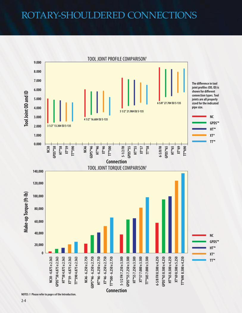
The difference in tool
HT™
XT®
TT™

2-5www.GrantPrideco.com
ROTARY-SHOULDERED CONNECTIONS
Rotary-Shouldered Connection
Leading the industry, Grant Prideco has further refined the
development and optimization of rotary-shouldered connection
design with the TurboTorque™ connection. TurboTorque is the
industry’s first rotary-shouldered connection that is composed of
four distinct configurations, optimized to best meet the specific
and differing needs of each individual pipe size (see chart on next
page).
The patented TurboTorque connection is the industry’s highest
performance connection available in sizes for 2-3/8 inch through
6-5/8 inch drill pipe and provides the following benefits:
Double-Start Thread
TurboTorque™ connections are the industry’s first rotary-
shouldered connections to offer a double-start thread form. Dual
threads, 180 degrees apart, reduce the number of turns from stab
to makeup by 50%, saving significant rig time. The resulting
increase in thread lead angle provides an increased torque capacity
of 12%.

2-6
ROTARY-SHOULDERED CONNECTIONS
Stronger Tool Joints
Standard drill pipe tool joints are made of steel with Specified
Minimum Yield Strength (SMYS) of 120,000 psi (120 ksi SMYS).
Historically, efforts to increase the
tool joint yield strength have resulted
in reduced fracture toughness and
increased susceptibility to fatigue
crack propagation. TurboTorque
connections are engineered specifi-
cally for use with 130 ksi SMYS tool
joints, meeting the increased fracture
toughness required by API and
proprietary manufacturing standards
such as NS-1™, DS-1™ and NORSOK. In
addition, the TurboTorque thread
form and tool joint geometry have
been engineered to provide industry-
leading fatigue performance. The result is a rotary-shouldered
connection with increased torque capacity, reduced connection
profile, greater fishability and increased hydraulic performance.
of steel with Specified
000 psi (120 ksi SMYS).
1 2 3 4
2 3/8 to 2 7/8 in Increased tensile capacity Increased torque capacity Optimized hydraulics Speed of makeup
3 1/2 to 4 1/2 in Increased torque capacity Speed of makeup Optimized hydraulics
5 to 5 7/8 in Speed of makeup Optimized hydraulics Increased torque capacity
6 5/8 in Speed of makeup Reduced make-up torque Optimized hydraulics

2-7www.GrantPrideco.com
Increased Torque Capacity
TurboTorque connections provide more torque capacity than any
other double-shouldered connection in the industry today, and the
“torque on demand” feature provides an additional 8% of torque
capacity for those unusual drilling situations.
Three make-up torque (MUT) values are provided for each
TurboTorque connection:
Minimum torque is the least amount of MUT acceptable to ensure
that the connection will function properly. Minimum MUT is
normally only considered in cases when the recommended MUT
may exceed capacity of the rig equipment, such as large diameter,
high-strength drill strings or landing strings.
Recommended MUT is used for normal drilling operations. In most
situations, it provides enough torque to prevent downhole makeup
while minimizing connection stress.
TurboTorque connections are the first in the industry to provide a
Turbo-MUT. Also known as “torque-on-demand”, Turbo-MUT
provides an additional 8% of torque capacity for those unusual
drilling situations when additional torque is required. Most of the
testing and design validation for the TurboTorque family were
conducted on connections made up to the Turbo-MUT value.
Extensive testing allows the Turbo-MUT to be used confidently
without having to consult Grant Prideco.
Thread start 1
Thread start 2
ROTARY-SHOULDERED CONNECTIONS
6-5/
8 FH
- 8.
500
x 4.
250
XT69
- 8.
500
x 5.
250
0
20,000
40,000
60,000
80,000
100,000
12,100
22,20025,500 26,900
42,100
50,500
43,500
56,60062,100
65,500
100,300
82,100
Connection
Mak
e-up
Torq
ue (f
t-lb
)
NC4
6 - 6
.250
x 2
.750
XT46
- 6.
250
x 3.
250
5-1/
2 FH
- 7.
250
x 3.
500
XT57
- 7.
000
x 4.
250
NC3
8 - 4
.875
x 2
.563
XT39
- 4.
875
x 2.
563
63,100
(min.)
TT69
0 - 8
.250
x 5
.500
TT58
5 - 7
.000
x 4
.500
TT50
0 - 6
.250
x 3
.500
TT39
0 4.
875
x 2.
688
120,000
MAKE-UP TORQUE COMPARISON†

2-8
ROTARY-SHOULDERED CONNECTIONS
Optimized Connection Taper
Taper is the controlling factor in the final configuration of a
rotary-shouldered connection. The TurboTorque taper is engineered
to ensure a balance between the pin and box, maximizing
connection stiffness and fatigue resistance. The taper is designed
to deliver maximum tradeoff between tensile strength, torque
capacity and connection profile. The result is a balanced pin and
box, reduced connection profile, connection stiffness and fatigue
resistance, greater fishability, increased hydraulic performance and
optimum balance between all performance parameters.
Optimized Hydraulic Performance
The refinement of the TurboTorque design and 130 ksi SMYS tool
joints mean the tool joint ID can be increased for diminished
pressure loss through the drill string. In comparison to Grant
Prideco’s XT® connection, tool joint ID can often be increased
1/8 of an inch or more. For a given hole size, TurboTorque’s slim
outside diameter often permits the use of a larger pipe size, which
significantly increases hydraulic performance. More hydraulic
horsepower at the bit saves operational cost and enables drilling
of deeper wells.

2-9www.GrantPrideco.com
High–Performance Thread Form
TurboTorque’s thread height is optimized for each of the four design
configurations. The thread form incorporates a unique dual-root
radius, larger than the root radii of API and even XT® connections,
significantly reducing the connection peak stress.
Save Time, Cut Costs
A TurboTorque connection requires the same running procedures
as the XT connection. However, TurboTorque’s double-start thread,
faster taper and deeper stabbing greatly reduces the turns to
makeup. The resulting time saved has a marked effect on rig
economics. Compared to competitive premium rotary-shouldered
connections, TurboTorque connections often pay for themselves on
the first well, then continue to provide operational savings.
THREAD FORM COMPARISONS
API NC V-0.038R
API FH V-0.050
XT®(0.042” root radius)
XT®
(0.052” x 0.060” dual root radius)
(0.065” x 0.065” dual-root radius)
ROTARY-SHOULDERED CONNECTIONS

2-10
ROTARY-SHOULDERED CONNECTIONS
Enabling Technology – Drill Deeper, Faster, Further
The TurboTorque connection’s torque capacity exceeds that of all
double-shouldered connections on the market. Its slim profile
decreases pressure loss through the tool joint and often allows the
use of a larger pipe size. The result: more mechanical and hydraulic
horsepower at the bit, enabling completion of world class wells.
Reduced Total Cost of Ownership
High-strength and high-toughness tool joints and a unique
dual-radius thread form have pushed the fatigue resistance of
TurboTorque connections far beyond previous industry limits. In
addition, TurboTorque connections combined with superior Grant
Prideco technology including engineered materials, quenched
and tempered weld zones, fatigue-resistance upset/weld-neck
geometry, quality processing and Platinum® hardbanding, are
proven to extend life, increase reliability and reduce total cost
of ownership.
100,000 1,000,000
Cycles to Failure, NIn
crea
sin
g B
endi
ng
Mom
ent
4-7/8” x 2-9/16” NC38 4-7/8” x 2-11/16” TurboTorque™ 390
200,000 300,000 400,000
100,000 1,000,000
Cycles to Failure, N
Incr
easi
ng
Ben
din
g M
omen
t
7-1/4” x 3-1/2” 5-1/2 FH 7” x 4-1/2” TurboTorque™ 585
200,000 300,000 400,000
FATIGUE PERFORMANCE†
TURBOTORQUE™ 390 AND API NC38
FATIGUE PERFORMANCE†
TURBOTORQUE™ 585 AND API 5-1/2 FH

2-11www.GrantPrideco.com
TURBOTORQUE™ CONNECTION MECHANICAL CHARACTERISTICS†
GradeTensile Connection
Tool Tool
in in in in
Standard 3.500 13.30 S-135 381,900 TurboTorque 380 4.750 2.688 14.42 16,800 20,200 21,900
Standard 3.500 15.50 S-135 451,100 TurboTorque 380 4.813 2.500 16.88 19,900 23,900 25,900
Streamline 4.000 14.00 S-135 403,500 TurboTorque 390 4.875 2.688 5.063 15.44 19,600 23,500 25,500
Standard 4.000 14.00 S-135 403,500 TurboTorque 420 5.250 2.938 15.79 23,700 28,400 30,800
Standard 4.000 15.70 S-135 456,900 TurboTorque 420 5.250 2.938 17.36 23,700 28,400 30,800
Streamline 4.500 16.60 S-135 468,300 TurboTorque 435 5.375 3.125 5.563 17.96 24,700 29,600 32,100
Standard 4.500 16.60 S-135 468,300 TurboTorque 485 6.000 3.563 18.50 31,500 37,800 40,900
Standard 4.500 20.00 S-135 581,200 TurboTorque 485 6.125 3.250 22.72 39,700 47,600 51,600
Streamline 5.000 19.50 S-135 560,800 TurboTorque 500 6.250 3.500 6.438 22.29 38,900 46,600 50,500
Standard 5.000 19.50 S-135 560,800 TurboTorque 525 6.500 3.875 22.11 38,200 45,800 49,600
Standard 5.000 25.60 S-135 746,400 TurboTorque 525 6.625 3.563 28.51 48,000 57,600 62,400
Streamline 5.500 21.90 S-135 620,600 TurboTorque 550 6.625 4.250 6.813 23.71 39,100 46,900 50,900
Standard 5.500 21.90 S-135 620,600 TurboTorque 585 7.000 4.500 24.08 47,800 57,300 62,100
Standard 5.500 24.70 S-135 704,300 TurboTorque 585 7.125 4.313 27.33 55,500 66,600 72,200
Streamline 5.875 23.40 S-135 666,500 TurboTorque 585 7.000 4.500 7.188 25.78 47,800 57,300 62,100
Streamline 5.875 26.30 S-135 757,100 TurboTorque 585 7.000 4.500 7.188 28.37 47,800 57,300 62,100
Standard 6.625 27.70 S-135 760,400 TurboTorque 690 8.250 5.500 30.15 63,100 75,800 82,100
ROTARY-SHOULDERED CONNECTIONS
2-12
Connection
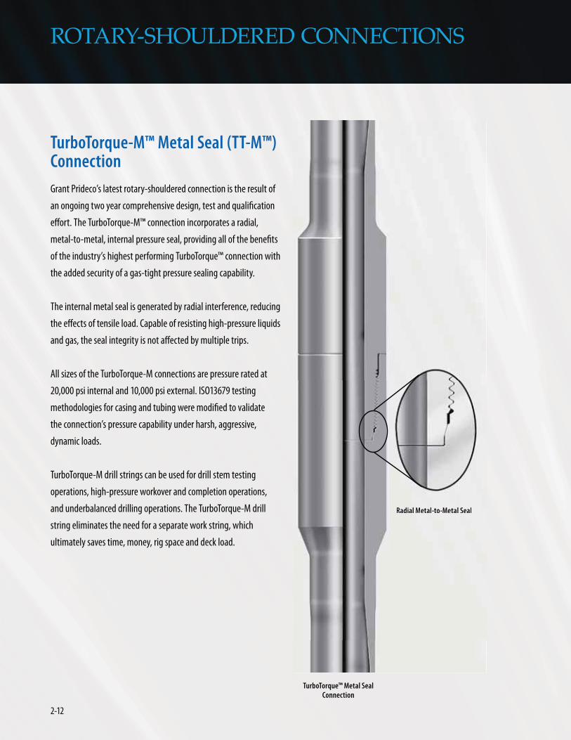
Grant Prideco’s latest rotary-shouldered connection is the result of
an ongoing two year comprehensive design, test and qualification
effort. The TurboTorque-M™ connection incorporates a radial,
metal-to-metal, internal pressure seal, providing all of the benefits
of the industry’s highest performing TurboTorque™ connection with
the added security of a gas-tight pressure sealing capability.
The internal metal seal is generated by radial interference, reducing
the effects of tensile load. Capable of resisting high-pressure liquids
and gas, the seal integrity is not affected by multiple trips.
All sizes of the TurboTorque-M connections are pressure rated at
20,000 psi internal and 10,000 psi external. ISO13679 testing
methodologies for casing and tubing were modified to validate
the connection’s pressure capability under harsh, aggressive,
dynamic loads.
TurboTorque-M drill strings can be used for drill stem testing
operations, high-pressure workover and completion operations,
and underbalanced drilling operations. The TurboTorque-M drill
string eliminates the need for a separate work string, which
ultimately saves time, money, rig space and deck load.
ROTARY-SHOULDERED CONNECTIONS
Radial Metal-to-Metal Seal
Connection
Radial Metal-to-Metal Seal

2-13www.GrantPrideco.com
ROTARY-SHOULDERED CONNECTIONS
In addition to providing a 20,000 psi internal and 10,000 psi
external pressure rating, TurboTorque-M™ connections provide
increased mechanical and hydraulic performance compared to
eXtreme® Torque-M™ (XT-M™) connections, while also providing
fatigue performance greater than standard API connections. In
comparison with XT-M, TurboTorque-M provides a 1/4 inch larger
ID for increased hydraulics, 8% additional working torque capacity
and 5,000 ft/lbs of additional rated internal working pressure
(see table).
TurboTorque-M connections are not interchangeable with any
other rotary-shouldered connection, including TurboTorque™
connections.
Connection
XT-M57 7.000 4.500 51,600
TurboTorque-M 585 7.000 4.250 55,903
MAKE-UP TORQUE COMPARISON†
4.250
4.500

2-14
Rotary-Shouldered Connection
The patented eXtreme® Torque (XT®) connection addresses the
requirements of many extreme drilling applications, including
extended reach drilling (ERD), horizontal drilling, deepwater, high
temperature high pressure (HTHP) and ultra-deep wells.
High-Performance Design
The eXtreme Torque connection is a patented, high-performance,
rotary-shouldered connection available in sizes from 2-3/8 inch
through 6-5/8 inch drill pipe. The eXtreme Torque connection
incorporates a second generation double-shouldered design. A
secondary internal torque shoulder on the nose of the pin offers an
additional friction surface and mechanical stop. The primary
external shoulder still serves as the connection’s sealing surface.
The eXtreme Torque connection design has an extended pin base,
pin nose and box counterbore. These sections are carefully
engineered to provide additional elastic deformation during
makeup, ensuring that the contact forces are properly proportioned
between the two shoulder surfaces.
Increased Torque Capacity
The XT connection offers significantly higher torsional capacity
than standard API connections, as well as Grant Prideco’s GPDS™
and HI-TORQUE™ connections. This additional capacity provides the
required torque for the most extreme drilling applications.
ROTARY-SHOULDERED CONNECTIONS

2-15www.GrantPrideco.com
ROTARY-SHOULDERED CONNECTIONS
Slim Profile
The XT® connection’s increased torsional strength allows for the
use of a streamlined tool joint that is sized for the pipe’s torsional
strength. XT connections can be configured with a smaller OD and
larger ID compared to standard API connections without sacrificing
torsional capacity. Often, XT connections permit the use of a larger
diameter drill pipe, providing improved hydraulic efficiency, better
hole cleaning and greater buckling strength for horizontal and
extended reach applications without sacrificing torsional strength
or fishability.
True Flush Inside Diameter
There is no gap or change in the inside diameter from the box to
the pin, creating a smoother flow with less turbulence. This feature
also eliminates the recess found in standard connections where
cement and solids can be trapped.
Rugged Durability
The robust XT connection design incorporates more steel in the
critical areas of the connection resulting in less refacing and fewer
recuts. In addition, because of the increased torsional capacity, the
XT connection greatly extends the life of the joint by tolerating
more OD wear.
Field Repairable
The XT connection can be refaced in an inspection yard or at the rig
site with a portable refacing tool. This flexibility can save time and
expenses by eliminating transportation and handling costs.
User Friendly
XT connections utilize the same running procedures as standard
API connections. The connection spins up freely until shouldered,
then is bucked up to the make-up torque. XT connections have a
more shallow taper, requiring a more shallow stab and slightly
more turns to makeup.

2-16
XT® CONNECTION MECHANICAL CHARACTERISTICS†
ROTARY-SHOULDERED CONNECTIONS
Grade Tensile Connection
Standard 3.500 13.30 S-135 381,900 XT38 4.750 2.563 14.59 11,500 18,800
Standard 3.500 15.50 S-135 451,100 XT38 4.750 2.438 14.76 12,300 20,500
Standard 4.000 14.00 S-135 403,500 XT39 4.875 2.688 5.250 15.54 12,400 21,200
Standard 4.000 15.70 S-135 456,900 XT39 5.000 2.563 5.313 17.54 14,700 24,500
Standard 4.500 16.60 S-135 468,300 XT46 6.250 3.250 19.74 26,000 42,100
Standard 4.500 20.00 S-135 581,200 XT46 6.250 3.250 23.03 26,000 42,100
Standard 5.000 19.50 S-135 560,800 XT50 6.500 3.750 22.39 28,000 46,200
Standard 5.000 25.60 S-135 746,400 XT50 6.625 3.500 28.64 32,600 54,400
Standard 5.500 21.90 S-135 620,600 XT54 6.625 4.000 24.30 29,000 49,900
Standard 5.500 24.70 S-135 704,300 XT54 6.625 4.000 6.813 26.73 29,000 49,900
Standard 5.875 23.40 S-135 666,500 XT57 7.000 4.250 26.41 33,800 56,600
Standard 5.875 26.40 S-135 757,100 XT57 7.000 4.250 29.00 33,800 56,600
Standard 6.625 25.20 S-135 697,400 XT69 8.500 5.250 29.98 59,400 100,300
Standard 6.625 27.70 S-135 760,400 XT69 8.500 5.250 31.98 59,400 100,300

2-17www.GrantPrideco.com
Rotary-Shouldered Connection
The patented XT-M™ connection is the industry’s first gas-tight,
pressure-rated rotary-shouldered connection. An eXtreme™ Torque
connection with a radial metal-to-metal internal pressure seal,
XT-M provides torsional strength comparable to XT® connections
combined with a gas-tight pressure sealing capability.
The gas-tight seal is generated by radial interference, reducing the
effects of tensile load. Capable of resisting high-pressure liquids
and gas, the seal integrity is not affected by multiple trips.
All sizes of the XT-M connections are pressure rated at 15,000 psi
internal and 10,000 psi external.
XT-M drill strings can be used for drill stem testing (DST) opera-
tions, high-pressure workover and completion operations, and
underbalanced drilling operations. An XT-M drill string eliminates
the need for a separate work string, which saves time, money and
rig space.
XT-M connections are not interchangeable with any other rotary-
shouldered connection, including XT connections.
ROTARY-SHOULDERED CONNECTIONS
Seal Connection
Radial Metal-to-Metal Seal

2-18
XT-M™ CONNECTION MECHANICAL CHARACTERISTICS†
ROTARY-SHOULDERED CONNECTIONS
Grade Tensile Connection
Standard 3.500 13.30 S-135 381,900 XT-M 38 4.750 2.563 14.59 13,900 16,700
Standard 3.500 15.50 S-135 451,100 XT-M 38 4.750 2.438 16.84 15,400 18,400
Standard 4.000 14.00 S-135 403,500 XT-M 39 4.875 2.688 5.250 15.54 15,700 18,900
Standard 4.000 15.70 S-135 456,900 XT-M 39 5.000 2.563 5.313 17.54 18,600 22,300
Standard 4.500 16.60 S-135 468,300 XT-M46 6.250 3.250 19.74 32,200 38,700
Standard 4.500 20.00 S-135 581,200 XT-M46 6.250 3.250 23.03 32,200 38,700
Standard 5.000 19.50 S-135 560,800 XT-M50 6.625 3.750 22.72 35,200 42,200
Standard 5.000 25.60 S-135 746,400 XT-M50 6.625 3.500 28.64 41,900 50,300
Standard 5.500 21.90 S-135 620,600 XT-M54 6.625 4.000 24.30 37,800 45,400
Standard 5.500 24.70 S-135 704,300 XT-M54 6.625 4.000 6.813 26.73 37,800 45,400
Standard 5.875 23.40 S-135 666,500 XT-M57 7.000 4.250 26.41 43,000 51,600
Standard 5.875 26.30 S-135 757,100 XT-M57 7.000 4.250 29.00 43,000 51,600
Standard 6.625 25.20 S-135 697,400 XT-M69 8.500 5.250 29.98 77,400 92,900
Standard 6.625 27.70 S-135 760,400 XT-M69 8.500 5.250 31.79 77,400 92,900
2-19www.GrantPrideco.com
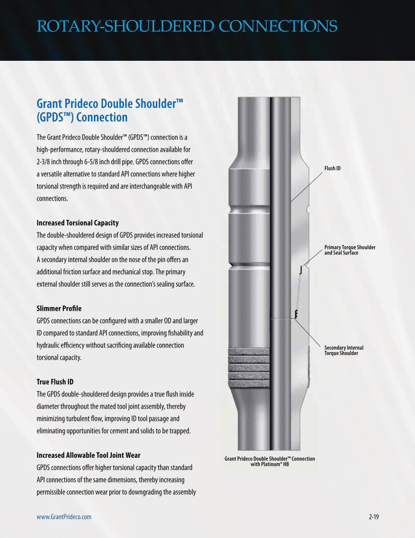
The Grant Prideco Double Shoulder™ (GPDS™) connection is a
high-performance, rotary-shouldered connection available for
2-3/8 inch through 6-5/8 inch drill pipe. GPDS connections offer
a versatile alternative to standard API connections where higher
torsional strength is required and are interchangeable with API
connections.
Increased Torsional Capacity
The double-shouldered design of GPDS provides increased torsional
capacity when compared with similar sizes of API connections.
A secondary internal shoulder on the nose of the pin offers an
additional friction surface and mechanical stop. The primary
external shoulder still serves as the connection’s sealing surface.
Slimmer Profile
GPDS connections can be configured with a smaller OD and larger
ID compared to standard API connections, improving fishability and
hydraulic efficiency without sacrificing available connection
torsional capacity.
True Flush ID
The GPDS double-shouldered design provides a true flush inside
diameter throughout the mated tool joint assembly, thereby
minimizing turbulent flow, improving ID tool passage and
eliminating opportunities for cement and solids to be trapped.
Increased Allowable Tool Joint Wear
GPDS connections offer higher torsional capacity than standard
API connections of the same dimensions, thereby increasing
permissible connection wear prior to downgrading the assembly
ROTARY-SHOULDERED CONNECTIONS

2-20
ROTARY-SHOULDERED CONNECTIONS
to Class 2. For example, an NC50 on 5 inch 19.50 lb S-135 drill pipe
is downgraded to Class 2 when the OD wears below 6-5/16 inches.
At this diameter, the tool joint is less than 80% as strong as
Premium Class pipe. The GPDS50 connection can tolerate wear
down to a diameter of 5-3/4 inch before its torsional strength falls
below 80% of the pipe strength.
Interchangeability
GPDS connections are fully interchangeable with corresponding
API FH or NC counterparts as shown below: 0.25
0.50
0.75
1.00
1.25
1.50
0.00
3/16"
5/16"
9/16"
7/8"
1-1/4"
3 1/2 in 13.30 lbs S-135
(5 in x 2 1/8 in)
5 1/2 in 21.90 lbs S-135
(7 1/2 in x 3 in)5 in 19.50 lbs S-135
(6 5/8 in x 2 3/4 in)
GPDS
38
(+16
7%)
GPDS
50
(+18
0%)
GPDS
55
(+12
2%)
NC 3
8
NC 5
0
5 1/
2 FH
Cum
ulat
ive
Wea
r (in
)
1/2"
Tool Joint Dimensions (in)
TOOL JOINT WEAR ALLOWANCE†
(NEW TO MINIMUM PREMIUM CLASS)
GPDS™ CONNECTION MECHANICAL CHARACTERISTICS†
Grade Tensile Connection
in in in
Standard 3.500 13.30 S-135 381,900 GPDS 38 4.875 2.563 14.82 12,100 15,400
Standard 3.500 15.50 S-135 451,100 GPDS 38 5.000 2.438 17.32 13,300 17,500
Standard 4.000 14.00 S-135 456,900 GPDS 40 5.250 2.688 16.18 15,400 19,600
Standard 4.000 15.70 S-135 456,900 GPDS 40 5.250 2.688 17.75 15,400 19,600
Standard 4.500 16.60 S-135 468,300 GPDS 46 6.000 3.000 19.58 23,500 31,800
Standard 4.500 20.00 S-135 581,200 GPDS 46 6.250 2.500 24.31 29,700 42,500
Standard 5.000 19.50 S-135 560,800 GPDS 50 6.500 3.250 23.42 30,800 43,100
Standard 5.000 25.60 S-135 746,400 GPDS 50 6.625 3.000 29.56 34,600 49,700
Standard 5.500 21.90 S-135 620,600 GPDS 55 7.000 4.000 25.32 33,500 43,800
Standard 5.500 24.70 S-135 704,300 GPDS 55 7.000 4.000 27.74 33,500 43,800
Standard 5.875 23.40 S-135 666,500 GPDS 55 7.000 4.000 27.02 33,500 43,800
Standard 5.875 26.30 S-135 704,300 GPDS 55 7.000 4.000 29.58 33,500 43,800
Standard 6.625 27.70 S-135 760,400 GPDS 65 8.000 4.875 31.21 47,800 63,600
GPDS26 NC26
GPDS31 NC31
GPDS38 NC38
GPDS40 NC40
GPDS46 NC46
GPDS50 NC50
GPDS55 5 1/2 FH
GPDS65 6 5/8 FH
INTERCHANGEABILITY TABLE

2-21www.GrantPrideco.com
ROTARY-SHOULDERED CONNECTIONS
®Rotary-Shouldered Connection
The HI-TORQUE® connection is a patented, high-performance,
rotary-shouldered connection available in sizes for 2-3/8 inch
through 6-5/8 inch drill pipe.
Increased Torsional Capacity
The HI-TORQUE connection’s double-shouldered design provides
increased torsional capacity as compared to similar sized API
connections. A secondary internal shoulder on the nose of the pin
offers an additional friction surface and mechanical stop. The
primary external shoulder still serves as the connection’s sealing
surface. HI-TORQUE connections are designed with an extended pin
base, pin nose and box counterbore. These sections are carefully
engineered to provide additional elastic deformation during
makeup. This process ensures that the contact forces are properly
proportioned between the two shoulder surfaces.
® Connection with ™

2-22
TORSIONAL YIELD STRENGTH†
HI-TORQUE® CONNECTION VS. CONVENTIONAL TOOL JOINT
0
20
40
60
80
100
Tors
iona
l Cap
acit
y (1
,000
ft-lb
s)
4 7/8 x 2 9/16 6 5/8 x 3 7 x 4
Tool Joint Dimensions (in)
29,500
20,200
57,800 55,900
82,600
77,800
HT3
8 +
46%
NC5
0
NC3
8
HT5
0 +
43%
HT5
5 +
39%
51 /2 in
FH
ROTARY-SHOULDERED CONNECTIONS
Slimmer Profile
HI-TORQUE® connections can be configured with a smaller OD and
larger ID compared to standard API connections, improving
fishability and hydraulic efficiency without sacrificing available
connection torsional capacity. The accompanying figure illustrates
the smaller OD and larger ID for HI-TORQUE connections compared
to standard API connections with identical torsional capacity.
NC38 AND HT™38 CONNECTIONSWITH 2-9/16 INCH ID
WEAR ALLOWANCE COMPARISON†
True Flush ID
The HI-TORQUE double-shoulder design provides a true flush inside
diameter throughout the mated tool joint assembly, thereby
minimizing turbulent flow, improving ID tool passage and
eliminating opportunities for cement and solids to be trapped.
Increased Allowable Tool Joint Wear
HI-TORQUE connections offer higher torsional capacity than
standard API connections of the same dimensions, thereby
increasing permissible connection wear prior to downgrading
the assembly to Class 2. The accompanying chart illustrates
the additional wear allowance provided by HT38 as compared
with NC38.
Interchangeability
HI-TORQUE connections are not interchangeable with API or
other types of rotary-shouldered connections.
10
15
20
25
30
4.8134.875 4.750 4.688 4.625 4.563 4.500
HT38
NC38
80% Torsional Strength 3 1/2 13.30 G-105 Premium Class Drill Pipe
80% Torsional Strength3 1/2 13.30 S-135 Premium Class Drill Pipe
Tors
iona
l Str
engt
h (1
,000
ft-lb
s)
Tool Joint OD (in)

2-23www.GrantPrideco.com
HI-TORQUE® CONNECTION MECHANICAL CHARACTERISTICS†
ROTARY-SHOULDERED CONNECTIONS
Grade Tensile Connection
in in in in
Standard 3.500 13.30 S-135 381,900 HT38 4.750 2.438 14.80 10700 17000
Standard 3.500 13.30 S-135 381,900 HT38 4.875 2.563 14.87 12200 17700
Standard 3.500 13.30 S-135 381,900 HT38 5.000 2.563 15.11 12300 17700
Standard 3.500 15.50 S-135 451,100 HT38 4.875 2.563 16.95 12200 17700
Standard 4.000 14.00 S-135 403,500 HT38 4.938 2.563 15.88 12300 17700
Standard 4.000 14.00 S-135 403,500 HT40 5.250 2.688 16.18 15500 21500
Standard 4.000 15.70 S-135 456,900 HT38 4.875 2.563 5.063 17.23 12200 17700
Standard 4.500 16.60 S-135 468,300 HT46 6.250 3.250 19.59 20500 28500
Standard 4.500 20.00 S-135 581,200 HT46 6.250 3.000 23.34 23900 34600
Standard 5.000 19.50 S-135 560,800 HT50 6.625 3.500 23.10 27200 39700
Standard 5.000 25.60 S-135 746,400 HT50 6.625 3.000 29.40 34900 53300
Standard 5.500 21.90 S-135 620,600 HT55 7.000 3.750 25.89 35900 52600
Standard 5.500 21.90 S-135 620,600 HT55 7.000 4.000 25.16 33600 46300
Standard 5.500 24.70 S-135 704,300 HT55 7.000 3.750 28.14 35900 52600
Standard 5.500 24.70 S-135 704,300 HT55 7.000 4.000 27.59 33600 46300

2-24
Cycles to Failure
Mic
ro S
trai
n (u
e)
100,000 1,000,000
1,288,717
10,000,000 100,000,000
700
600
500
400
300
200
100
0
On average. DC™58 is at least 9 times
more fatigue resistant than 6-5/8 Reg.
12,220,611
6-5/8 Reg Actual
6-5/8 Reg Average
DC™58 Connection Actual
DC™58 Connection Average
The Grant Prideco Drill Collar (DC™) connection provides a step
change in BHA connection performance. The enhanced connection
is ideally suited for drilling programs plagued with aggressive drill
string dynamics (axial, lateral and torsional vibrations), H2S
environments and wells equipped with The IntelliServ® Network.
A New Paradigm in Fatigue Resistance
The DC connection features a unique fatigue
resistant thread form that incorporates a generous
dual thread root radius of 0.060 inch and 0.065
inch. The larger dual-root radius significantly
reduces peak stresses in the thread root and
extends connection fatigue life. The DC connection
pins also include a stress relief feature. Laboratory
test results indicate that the DC58 connection
provides a near full order of magnitude increase in
fatigue performance, at least nine times improved,
compared to API 6-5/8 inch Regular connection.
ROTARY-SHOULDERED CONNECTIONS
CONNECTION S-N COMPARISON†
2-25www.GrantPrideco.com
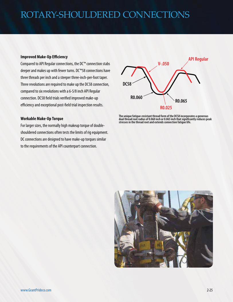
Improved Make-Up Efficiency
Compared to API Regular connections, the DC™ connection stabs
deeper and makes up with fewer turns. DC™58 connections have
three threads per inch and a steeper three-inch-per-foot taper.
Three revolutions are required to make up the DC58 connection,
compared to six revolutions with a 6-5/8 inch API Regular
connection. DC58 field trials verified improved make-up
efficiency and exceptional post-field trial inspection results.
Workable Make-Up Torque
For larger sizes, the normally high makeup torque of double-
shouldered connections often tests the limits of rig equipment.
DC connections are designed to have make-up torques similar
to the requirements of the API counterpart connection.
R0.065R0.060
DC58
R0.025
V-.050API Regular
ROTARY-SHOULDERED CONNECTIONS

2-26
IntelliServ® Network Compatible
In order to complete a telemetry network from the bit to the
surface, DC™ double-shouldered drill collars provide an ideal
location for the IntelliServ induction coil placement, with each coil
installed in a protective groove in the secondary torque shoulder.
Minimal Recut Loss
The steeper taper of the DC connection reduces loss from recutting
the connections. Compared to the API 6-5/8 inch Regular connec-
tion, the DC58 connection saves just over one inch of material after
each pin recut, and just over 1/2 inch after each box recut.
ROTARY-SHOULDERED CONNECTIONS
Connection inch
Thread Root Torsional Tensile Min
in in in
API 6 5/8 in Regular(1) 2 4 0.025 81,120 1,601,955 50,700 6.2 3.169 1.776
DC™58 Connection(2) 3 3 0.060 and 0.065 99,793 1,653,446 62,371 2.8 2.043 1.208
1 -1 -3.4 -1.126
DC CONNECTION MECHANICAL CHARACTERISTICS†

2-27www.GrantPrideco.com
ROTARY-SHOULDERED CONNECTIONS
Resistant Thread Connections
The SST® and SRT® connections are proprietary connections that
provide increased durability and fatigue resistance compared to
a standard API connection.
The SST connection involves a modification to the pin thread
only; the mating box thread remains standard. Completely
interchangeable with the standard API connections, the SST
connection requires no crossovers or special rig handling
procedures. The SST pin incorporates two primary features. First,
the thread form has an enlarged root radius grooved into the
slab flank. Second, the pin thread body is machined on a slightly
flatter taper than that of the box, effectively behaving like a
variable pitch thread.
The SRT connection involves a modification to the box thread
only; the mating pin thread remains standard. Completely
interchangeable with the standard API connections, the SRT
connection requires no crossovers or special rig handling
procedures. The thread form has an enlarged root radius
grooved into the slab flank.
thread root.
Root Radius
Loa
d Ca
rrie
d by
Pin
Thr
ead
(%)
0
5
10
15
20
25
30
1 10
DISTRIBUTION OF TENSILE LOAD CARRIED BY THREADS†
FROM MAKEUP ON NC46 & NC46 SST® THREADS

2-28
Rotary-Shouldered Connections
Grant Prideco provides drill pipe with API and public domain rotary-
shouldered connections. Typical connection configurations are
shown on the following tables. Additional configurations can be
provided upon request. Contact Grant Prideco for additional
information.
An interchange chart for API connection designations is followed by
API Drill Pipe Data Tables.
ROTARY-SHOULDERED CONNECTIONS
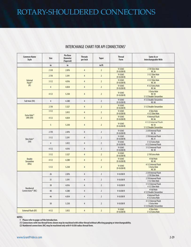
2-29www.GrantPrideco.com
StyleSize
Threads Thread
in in
InternalFlush(1)
(IF)
2 3/8 2.876 4 2V-0.065
(V-0.038 R)2 7/8 Slim Hole
NC 26
2 7/8 3.391 4 2V-0.065
(V-0.038 R)3 1/2 Slim Hole
NC 31
3 1/2 4.016 4 2V-0.065
(V-0.038 R)4 1/2 Slim Hole
NC 38
4 4.834 4 2V-0.065
(V-0.038 R)4 1/2 Extra Hole
NC 46
4 1/2 5.250 4 2V-0.065
(V-0.038 R)
5 Extra HoleNC 50
5 1/2 Double Streamline
Full Hole (FH) 4 4.280 4 2V-0.065
(V-0.038 R)4 1/2 Double Streamline
NC 40
Extra Hole(1)
(XH) (EH)
2 7/8 3.327 4 2V-0.065
(V-0.038 R)3 1/2 Double Streamline
3 1/2
3.812 4 2V-0.065
(V-0.038 R)4 Slim Hole
4 1/2 Slim Hole
4 1/2 4.834 4 2V-0.065
(V-0.038 R)4 Internal Flush
NC 46
5 5.250 4 2V-0.065
(V-0.038 R)
4 1/2 Slim HoleNC 50
5 1/2 Double Streamline
Slim Hole(1)
(SH)
2 7/8 2.876 4 2V-0.065
(V-0.038 R)2 3/8 Internal Flush
NC 26
3 1/2 3.391 4 2V-0.065
(V-0.038 R)2 7/8 Internal Flush
NC 31
4 3.812 4 2V-0.065
(V-0.038 R)3 1/2 Extra Hole
4 1/2 External Flush
4 1/2 4.016 4 2V-0.065
(V-0.038 R)3 1/2 Internal Flush
NC 38
Double Streamline
(DSL)
3 1/2 3.327 4 2V-0.065
(V-0.038 R)2 7/8 Extra Hole
4 1/2 4.280 4 2V-0.065
(V-0.038 R)4 Full Hole
NC 40
5 1/2 5.250 4 2V-0.065
(V-0.038 R)
4 1/2 Internal Flush5 Extra Hole
NC 50
Numbered Connections(2) (NC)
26 2.876 4 2 V-0.038 R2 3/8 Internal Flush
2 7/8 Slim Hole
31 3.391 4 2 V-0.038 R2 7/8 Internal Flush
3 1/2 Slim Hole
38 4.016 4 2 V-0.038 R3 1/2 Internal Flush
4 1/2 Slim Hole
40 4.280 4 2 V-0.038 R4 Full Hole
4 1/2 Double Streamline
46 4.834 4 2 V-0.038 R4 Internal Flush4 1/2 Extra Hole
50 5.250 4 2 V-0.038 R4 1/2 Internal Flush
5 Extra Hole5 1/2 Double Streamline
External Flush (EF) 4 1/2 3.812 4 2V-0.065
(V-0.038 R)4 Slim Hole
3 1/2 Extra Hole
INTERCHANGE CHART FOR API CONNECTIONS†
ROTARY-SHOULDERED CONNECTIONS
4 1/2 Internal Flush

2-30
Size Grade
Torsional Yield Tensile Yield Wall Section Section
Modulus Modulus
in in in cu in cu in
2 3/8 6.65
E-75 EU 6,300 138,200 0.280 1.815 1.843 0.867 1.733 15,474 15,599E-75 EU 6,300 138,200 0.280 1.815 1.843 0.867 1.733 15,474 15,599X-95 EU 7,900 175,100 0.280 1.815 1.843 0.867 1.733 19,600 19,759X-95 EU 7,900 175,100 0.280 1.815 1.843 0.867 1.733 19,600 19,759
G-105 EU 8,800 193,500 0.280 1.815 1.843 0.867 1.733 21,663 21,839G-105 EU 8,800 193,500 0.280 1.815 1.843 0.867 1.733 21,663 21,839S-135 EU 11,300 248,800 0.280 1.815 1.843 0.867 1.733 27,853 28,079S-135 EU 11,300 248,800 0.280 1.815 1.843 0.867 1.733 27,853 28,079
2 7/8 6.85
E-75 IU 8,100 135,900 0.217 2.441 1.812 1.121 2.241 9,907 10,467E-75 EU 8,100 135,900 0.217 2.441 1.812 1.121 2.241 9,907 10,467X-95 IU 10,200 172,100 0.217 2.441 1.812 1.121 2.241 12,548 12,940X-95 EU 10,200 172,100 0.217 2.441 1.812 1.121 2.241 12,548 12,940G-105 IU 11,300 190,300 0.217 2.441 1.812 1.121 2.241 13,869 14,020G-105 EU 11,300 190,300 0.217 2.441 1.812 1.121 2.241 13,869 14,020S-135 IU 14,500 244,600 0.217 2.441 1.812 1.121 2.241 17,832 17,034S-135 EU 14,500 244,600 0.217 2.441 1.812 1.121 2.241 17,832 17,034
2 7/8 10.40
E-75 EU 11,600 214,300 0.362 2.151 2.858 1.602 3.204 16,526 16,509E-75 EU 11,600 214,300 0.362 2.151 2.858 1.602 3.204 16,526 16,509E-75 EU 11,600 214,300 0.362 2.151 2.858 1.602 3.204 16,526 16,509X-95 EU 14,600 271,500 0.362 2.151 2.858 1.602 3.204 20,933 20,911X-95 IU 14,600 271,500 0.362 2.151 2.858 1.602 3.204 20,933 20,911X-95 EU 14,600 271,500 0.362 2.151 2.858 1.602 3.204 20,933 20,911
G-105 EU 16,200 300,100 0.362 2.151 2.858 1.602 3.204 23,137 23,112G-105 IU 16,200 300,100 0.362 2.151 2.858 1.602 3.204 23,137 23,112G-105 EU 16,200 300,100 0.362 2.151 2.858 1.602 3.204 23,137 23,112S-135 EU 20,800 385,800 0.362 2.151 2.858 1.602 3.204 29,747 29,716S-135 IU 20,800 385,800 0.362 2.151 2.858 1.602 3.204 29,747 29,716S-135 EU 20,800 385,800 0.362 2.151 2.858 1.602 3.204 29,747 29,716
3 1/2 9.50
E-75 EU 14,100 194,300 0.254 2.992 2.590 1.961 3.923 9,525 10,001E-75 IU 14,100 194,300 0.254 2.992 2.590 1.961 3.923 9,525 10,001E-75 EU 14,100 194,300 0.254 2.992 2.590 1.961 3.923 9,525 10,001X-95 EU 17,900 246,100 0.254 2.992 2.590 1.961 3.923 12,065 12,077X-95 IU 17,900 246,100 0.254 2.992 2.590 1.961 3.923 12,065 12,077X-95 EU 17,900 246,100 0.254 2.992 2.590 1.961 3.923 12,065 12,077
G-105 EU 19,800 272,000 0.254 2.992 2.590 1.961 3.923 13,335 13,055G-105 IU 19,800 272,000 0.254 2.992 2.590 1.961 3.923 13,335 13,055G-105 EU 19,800 272,000 0.254 2.992 2.590 1.961 3.923 13,335 13,055S-135 EU 25,500 349,700 0.254 2.992 2.590 1.961 3.923 17,145 15,748S-135 IU 25,500 349,700 0.254 2.992 2.590 1.961 3.923 17,145 15,748S-135 EU 25,500 349,700 0.254 2.992 2.590 1.961 3.923 17,145 15,748
3 1/2 13.30
E-75 EU 18,600 271,600 0.368 2.764 3.621 2.572 5.144 13,800 14,113E-75 IU 18,600 271,600 0.368 2.764 3.621 2.572 5.144 13,800 14,113E-75 EU 18,600 271,600 0.368 2.764 3.621 2.572 5.144 13,800 14,113X-95 EU 23,500 344,000 0.368 2.764 3.621 2.572 5.144 17,480 17,877X-95 IU 23,500 344,000 0.368 2.764 3.621 2.572 5.144 17,480 17,877X-95 EU 23,500 344,000 0.368 2.764 3.621 2.572 5.144 17,480 17,877
G-105 EU 26,000 380,200 0.368 2.764 3.621 2.572 5.144 19,320 19,758G-105 IU 26,000 380,200 0.368 2.764 3.621 2.572 5.144 19,320 19,758G-105 EU 26,000 380,200 0.368 2.764 3.621 2.572 5.144 19,320 19,758S-135 EU 33,400 488,800 0.368 2.764 3.621 2.572 5.144 24,840 25,404S-135 IU 33,400 488,800 0.368 2.764 3.621 2.572 5.144 24,840 25,404S-135 EU 33,400 488,800 0.368 2.764 3.621 2.572 5.144 24,840 25,404
3 1/2 15.50
E-75 EU 21,100 322,800 0.449 2.602 4.304 2.923 5.847 16,838 16,774X-95 EU 26,700 408,800 0.449 2.602 4.304 2.923 5.847 21,328 21,247
G-105 EU 29,500 451,900 0.449 2.602 4.304 2.923 5.847 23,573 23,484G-105 EU 29,500 451,900 0.449 2.602 4.304 2.923 5.847 23,573 23,484S-135 EU 38,000 581,000 0.449 2.602 4.304 2.923 5.847 30,308 30,194S-135 EU 38,000 581,000 0.449 2.602 4.304 2.923 5.847 30,308 30,194
ROTARY-SHOULDERED CONNECTIONS
DRILL PIPE TABLES†: 2 3/8 in – 3 1/2 in

2-31
ROTARY-SHOULDERED CONNECTIONS
Size Grade
Connection Torsional
Yield Tensile
Yield Torsional Ratio Tool
in in in in in
2 3/8 6.65
E-75 EU NC26 3 3/8 1 3/4 6,900 313,700 3,900 1.10 9 10E-75 EU 2 3/8 SLH90 3 1/4 1 13/16 6,900 270,200 3,700 1.10 9 10X-95 EU NC26 3 3/8 1 3/4 6,900 313,700 3,900 0.87 9 10X-95 EU 2 3/8 SLH90 3 1/4 1 13/16 6,900 270,200 3,700 0.87 9 10
G-105 EU NC26 3 3/8 1 3/4 6,900 313,700 3,900 0.78 9 10G-105 EU 2 3/8 SLH90 3 1/4 1 13/16 6,900 270,200 3,700 0.78 9 10S-135 EU NC26 3 5/8 1 1/2 9,000 390,300 4,900 0.80 9 10S-135 EU 2 3/8 SLH90 3 1/4 1 11/16 7,700 311,500 4,200 0.68 9 10
2 7/8 6.85
E-75 IU NC26 3 3/8 1 3/4 6,900 313,700 3,900 0.85 9 10E-75 EU NC31 4 1/8 2 5/32 11,500 434,500 6,200 1.42 9 11X-95 IU NC26 3 1/2 1 1/2 8,800 390,300 4,900 0.86 9 10X-95 EU NC31 4 1/8 2 5/32 11,500 434,500 6,200 1.13 9 11G-105 IU NC26 3 5/8 1 3/4 7,200 313,700 3,900 0.64 9 10G-105 EU NC31 4 1/8 2 5/32 11,500 434,500 6,200 1.02 9 11S-135 IU NC26 3 5/8 1 1/2 9,000 390,300 4,900 0.62 9 10S-135 EU NC31 4 1/8 2 1/8 11,900 447,100 6,400 0.82 9 11
2 7/8 10.40
E-75 EU NC31 4 1/8 2 1/8 11,900 447,100 6,400 1.03 9 11E-75 EU NC26 3 1/2 1 1/2 8,800 390,300 4,900 0.76 9 10E-75 EU 2 7/8 SLH90 3 7/8 2 13,100 444,000 6,900 1.13 9 11X-95 EU NC31 4 1/8 2 13,200 495,700 7,100 0.90 9 11X-95 IU NC26 3 1/2 1 1/2 8,800 390,300 4,900 0.60 9 10X-95 EU 2 7/8 SLH90 3 7/8 2 13,100 444,000 6,900 0.90 9 11
G-105 EU NC31 4 1/8 2 13,200 495,700 7,100 0.81 9 11G-105 IU NC26 3 1/2 1 1/2 8,800 390,300 4,900 0.54 9 10G-105 EU 2 7/8 SLH90 3 7/8 2 13,100 444,000 6,900 0.81 9 11S-135 EU NC31 4 1/8 2 13,200 495,700 7,100 0.63 9 11S-135 IU NC26 3 5/8 1 1/2 9,000 390,300 4,900 0.43 9 10S-135 EU 2 7/8 SLH90 3 7/8 2 13,100 444,000 6,900 0.63 9 11
3 1/2 9.50
E-75 EU NC38 4 3/4 2 11/16 18,100 587,300 9,700 1.28 10 12.5E-75 IU NC31 4 1/8 2 1/8 11,900 447,100 6,400 0.84 9 11E-75 EU 3 1/2 SLH90 4 3/4 2 11/16 18,688 534,200 11,100 1.33 10 12.5X-95 EU NC38 4 3/4 2 11/16 18,100 587,300 9,700 1.01 10 12.5X-95 IU NC31 4 1/8 2 13,200 495,700 7,100 0.74 9 11X-95 EU 3 1/2 SLH90 4 3/4 2 11/16 18,700 534,200 11,100 1.04 10 12.5
G-105 EU NC38 4 3/4 2 11/16 18,100 587,300 9,700 0.91 10 12.5G-105 IU NC31 4 1/8 2 13,200 495,700 7,100 0.67 9 11G-105 EU 3 1/2 SLH90 4 3/4 2 11/16 18,700 534,200 11,100 0.94 10 12.5S-135 EU NC38 4 7/8 2 9/16 20,200 649,200 10,700 0.79 10 12.5S-135 IU NC31 4 1/8 2 13,200 495,700 7,100 0.52 9 11S-135 EU 3 1/2 SLH90 4 3/4 2 9/16 20,900 596,100 12,400 0.82 10 12.5
3 1/2 13.30
E-75 EU NC38 4 3/4 2 11/16 18,100 587,300 9,700 0.97 10 12.5E-75 IU NC31 4 1/8 2 13,200 495,700 7,100 0.71 9 11E-75 EU 3 1/2 SLH90 4 3/4 2 11/16 18,700 534,200 11,100 1.01 10 12.5X-95 EU NC38 5 2 9/16 20,300 649,200 10,700 0.86 10 12.5X-95 IU NC31 4 1/8 2 13,200 495,700 7,100 0.56 9 11X-95 EU 3 1/2 SLH90 4 3/4 2 11/16 18,700 534,200 11,100 0.80 10 12.5
G-105 EU NC38 5 2 7/16 22,200 708,100 11,700 0.85 10 12.5G-105 IU NC31 4 1/8 2 13,200 495,700 7,100 0.51 9 11G-105 EU 3 1/2 SLH90 4 3/4 2 9/16 20,900 596,100 12,400 0.80 10 12.5S-135 EU NC38 5 2 1/8 26,500 842,400 14,000 0.79 10 12.5S-135 IU NC31 4 1/8 2 13,200 495,700 7,100 0.40 9 11S-135 EU 3 1/2 SLH90 4 3/4 2 9/16 20,900 596,100 12,400 0.63 10 12.5
3 1/2 15.50
E-75 EU NC38 5 2 9/16 20,300 649,200 10,700 0.96 10 12.5X-95 EU NC38 5 2 7/16 22,200 708,100 11,700 0.83 10 12.5
G-105 EU NC38 5 2 1/8 26,500 842,400 14,000 0.90 10 12.5G-105 EU NC40 5 1/4 2 9/16 27,800 838,300 14,600 0.94 9 12S-135 EU NC38 5 2 1/8 26,500 842,400 14,000 0.70 10 12.5S-135 EU NC40 5 1/2 2 1/4 32,900 980,000 17,100 0.87 10 12.5
in in
7.17 3 3/16 1 5/8 0.134 0.1107.00 3 1/32 1 11/16 0.134 0.1077.17 3 1/4 1 5/8 0.134 0.1107.00 3 3/32 1 11/16 0.134 0.1077.17 3 9/32 1 5/8 0.134 0.1107.00 3 1/8 1 11/16 0.134 0.1077.62 3 13/32 1 3/8 0.132 0.1177.10 3 7/32 1 9/16 0.133 0.1097.19 3 9/32 1 5/8 0.236 0.1107.88 3 11/16 2 1/32 0.239 0.1207.50 3 3/8 1 3/8 0.234 0.1157.88 3 3/4 2 1/32 0.239 0.1207.46 3 13/32 1 5/8 0.236 0.1147.88 3 13/16 2 1/32 0.239 0.1207.64 3 17/32 1 3/8 0.234 0.1177.91 3 29/32 2 0.239 0.121
11.14 3 13/16 2 0.188 0.17010.79 3 13/32 1 3/8 0.183 0.16510.95 3 19/32 1 7/8 0.187 0.16811.27 3 29/32 1 7/8 0.187 0.17210.76 NA 1 3/8 0.183 0.16510.95 3 11/16 1 7/8 0.187 0.16811.27 3 15/16 1 7/8 0.187 0.17210.76 NA 1 3/8 0.183 0.16510.95 3 23/32 1 7/8 0.187 0.16811.29 4 1/16 1 7/8 0.187 0.17310.90 NA 1 3/8 0.183 0.16710.95 3 27/32 1 7/8 0.187 0.16811.07 4 13/32 2 9/16 0.360 0.16910.49 3 7/8 2 0.354 0.16111.07 4 3/16 2 9/16 0.360 0.16911.07 4 15/32 2 9/16 0.360 0.16910.61 4 1 7/8 0.352 0.16211.07 4 9/32 2 9/16 0.360 0.16911.07 4 17/32 2 9/16 0.360 0.16910.61 4 1/16 1 7/8 0.352 0.16211.07 4 5/16 2 9/16 0.360 0.16911.45 4 21/32 2 7/16 0.358 0.17510.61 NA 1 7/8 0.352 0.16211.24 4 7/16 2 7/16 0.358 0.17214.24 4 1/2 2 9/16 0.310 0.21813.93 4 1/32 1 7/8 0.302 0.21314.24 4 9/32 2 9/16 0.310 0.21814.84 4 19/32 2 7/16 0.308 0.22713.93 NA 1 7/8 0.302 0.21314.24 4 3/8 2 9/16 0.310 0.21815.00 4 21/32 2 5/16 0.306 0.22913.93 NA 1 7/8 0.302 0.21314.41 4 7/16 2 7/16 0.308 0.22015.37 4 13/16 2 0.302 0.23513.93 NA 1 7/8 0.302 0.21314.41 4 19/32 2 7/16 0.308 0.22016.94 4 17/32 2 7/16 0.276 0.25917.11 4 21/32 2 5/16 0.274 0.26217.50 4 23/32 2 0.269 0.26817.24 4 15/16 2 7/16 0.276 0.26417.50 4 29/32 2 0.269 0.26818.31 5 3/32 2 1/8 0.271 0.280

2-32
ROTARY-SHOULDERED CONNECTIONS
Size Grade
Torsional Yield Tensile Yield Wall Section Section
Modulus Modulus
in in in cu in cu in
4 11.85
E-75 IU 19,500 230,800 0.262 3.476 3.077 2.700 5.400 8,597 8,381E-75 IU 19,500 230,800 0.262 3.476 3.077 2.700 5.400 8,597 8,381X-95 IU 24,700 292,300 0.262 3.476 3.077 2.700 5.400 10,889 9,978X-95 IU 24,700 292,300 0.262 3.476 3.077 2.700 5.400 10,889 9,978
G-105 IU 27,300 323,100 0.262 3.476 3.077 2.700 5.400 12,036 10,708G-105 IU 27,300 323,100 0.262 3.476 3.077 2.700 5.400 12,036 10,708S-135 IU 35,100 415,400 0.262 3.476 3.077 2.700 5.400 15,474 12,618S-135 IU 35,100 415,400 0.262 3.476 3.077 2.700 5.400 15,474 12,618
4 14.00
E-75 IU 23,300 285,400 0.330 3.340 3.805 3.229 6.458 10,828 11,354E-75 IU 23,300 285,400 0.330 3.340 3.805 3.229 6.458 10,828 11,354E-75 EU 23,300 285,400 0.330 3.340 3.805 3.229 6.458 10,828 11,354X-95 IU 29,500 361,500 0.330 3.340 3.805 3.229 6.458 13,716 14,382X-95 IU 29,500 361,500 0.330 3.340 3.805 3.229 6.458 13,716 14,382X-95 EU 29,500 361,500 0.330 3.340 3.805 3.229 6.458 13,716 14,382G-105 IU 32,600 399,500 0.330 3.340 3.805 3.229 6.458 15,159 15,896G-105 IU 32,600 399,500 0.330 3.340 3.805 3.229 6.458 15,159 15,896G-105 EU 32,600 399,500 0.330 3.340 3.805 3.229 6.458 15,159 15,896S-135 IU 41,900 513,600 0.330 3.340 3.805 3.229 6.458 19,491 20,141S-135 IU 41,900 513,600 0.330 3.340 3.805 3.229 6.458 19,491 20,141S-135 EU 41,900 513,600 0.330 3.340 3.805 3.229 6.458 19,491 20,141
4 15.70
E-75 IU 25,800 324,100 0.380 3.240 4.322 3.578 7.157 12,469 12,896E-75 IU 25,800 324,100 0.380 3.240 4.322 3.578 7.157 12,469 12,896E-75 EU 25,800 324,100 0.380 3.240 4.322 3.578 7.157 12,469 12,896X-95 IU 32,700 410,500 0.380 3.240 4.322 3.578 7.157 15,794 16,335X-95 IU 32,700 410,500 0.380 3.240 4.322 3.578 7.157 15,794 16,335X-95 EU 32,700 410,500 0.380 3.240 4.322 3.578 7.157 15,794 16,335G-105 IU 36,100 453,800 0.380 3.240 4.322 3.578 7.157 17,456 18,055G-105 IU 36,100 453,800 0.380 3.240 4.322 3.578 7.157 17,456 18,055G-105 EU 36,100 453,800 0.380 3.240 4.322 3.578 7.157 17,456 18,055S-135 IU 46,500 583,400 0.380 3.240 4.322 3.578 7.157 22,444 23,213S-135 IU 46,500 583,400 0.380 3.240 4.322 3.578 7.157 22,444 23,213S-135 EU 46,500 583,400 0.380 3.240 4.322 3.578 7.157 22,444 23,213
4 1/2 16.60
E-75 IEU 30,800 330,600 0.337 3.826 4.407 4.271 8.543 9,829 10,392E-75 EU 30,800 330,600 0.337 3.826 4.407 4.271 8.543 9,829 10,392E-75 IEU 30,800 330,600 0.337 3.826 4.407 4.271 8.543 9,829 10,392E-75 IEU 30,800 330,600 0.337 3.826 4.407 4.271 8.543 9,829 10,392E-75 EU 30,800 330,600 0.337 3.826 4.407 4.271 8.543 9,829 10,392X-95 IEU 39,000 418,700 0.337 3.826 4.407 4.271 8.543 12,450 12,765X-95 EU 39,000 418,700 0.337 3.826 4.407 4.271 8.543 12,450 12,765X-95 IEU 39,000 418,700 0.337 3.826 4.407 4.271 8.543 12,450 12,765X-95 IEU 39,000 418,700 0.337 3.826 4.407 4.271 8.543 12,450 12,765X-95 EU 39,000 418,700 0.337 3.826 4.407 4.271 8.543 12,450 12,765
G-105 IEU 43,100 462,800 0.337 3.826 4.407 4.271 8.543 13,761 13,825G-105 EU 43,100 462,800 0.337 3.826 4.407 4.271 8.543 13,761 13,825G-105 IEU 43,100 462,800 0.337 3.826 4.407 4.271 8.543 13,761 13,825G-105 IEU 43,100 462,800 0.337 3.826 4.407 4.271 8.543 13,761 13,825G-105 EU 43,100 462,800 0.337 3.826 4.407 4.271 8.543 13,761 13,825S-135 IEU 55,500 595,000 0.337 3.826 4.407 4.271 8.543 17,693 16,773S-135 EU 55,500 595,000 0.337 3.826 4.407 4.271 8.543 17,693 16,773S-135 IEU 55,500 595,000 0.337 3.826 4.407 4.271 8.543 17,693 16,773S-135 IEU 55,500 595,000 0.337 3.826 4.407 4.271 8.543 17,693 16,773S-135 EU 55,500 595,000 0.337 3.826 4.407 4.271 8.543 17,693 16,773
DRILL PIPE TABLES†: 4 in – 4 1/2 in

2-33www.GrantPrideco.com
ROTARY-SHOULDERED CONNECTIONS
Size Grade
Connection Torsional
Yield Tensile
Yield Torsional Ratio Tool
in in in in in
4 11.85
E-75 IU NC40 5 1/4 2 13/16 23,500 711,600 12,400 1.21 9 12E-75 IU 4 SH 4 3/4 2 9/16 15,300 512,000 8,100 0.78 9 12X-95 IU NC40 5 1/4 2 13/16 23,500 711,600 12,400 0.95 9 12X-95 IU 4 SH 4 3/4 2 9/16 15,300 512,000 8,100 0.62 9 12
G-105 IU NC40 5 1/4 2 13/16 23,500 711,600 12,400 0.86 9 12G-105 IU 4 SH 4 3/4 2 9/16 15,300 512,000 8,100 0.56 9 12S-135 IU NC40 5 1/2 2 9/16 28,100 838,300 14,600 0.80 9 12S-135 IU 4 SH 4 3/4 2 9/16 15,300 512,000 8,100 0.44 9 12
4 14.00
E-75 IU NC40 5 1/4 2 13/16 23,500 711,600 12,400 1.01 9 12E-75 IU 4 SH 4 3/4 2 7/16 17,100 570,900 9,100 0.73 9 12E-75 EU NC46 6 3 1/4 33,600 901,200 17,600 1.44 9 12X-95 IU NC40 5 1/4 2 11/16 25,700 776,400 13,500 0.87 9 12X-95 IU 4 SH 4 3/4 2 7/16 17,100 570,900 9,100 0.58 9 12X-95 EU NC46 6 3 1/4 33,600 901,200 17,600 1.14 9 12G-105 IU NC40 5 1/2 2 7/16 30,100 897,200 15,600 0.92 9 12G-105 IU 4 SH 4 3/4 2 7/16 17,100 570,900 9,100 0.52 9 12G-105 EU NC46 6 3 1/4 33,600 901,200 17,600 1.03 9 12S-135 IU NC40 5 1/2 2 36,400 1,080,100 18,900 0.87 9 12S-135 IU 4 SH 4 3/4 2 7/16 17,100 570,900 9,100 0.41 9 12S-135 EU NC46 6 3 39,200 1,048,400 20,500 0.94 9 12
4 15.70
E-75 IU NC40 5 1/4 2 13/16 23,500 711,600 12,400 0.91 9 12E-75 IU 4 H90 5 1/2 2 13/16 35,400 913,700 20,400 1.37 9 12E-75 EU NC46 6 3 39,200 1,048,400 20,500 1.52 9 12X-95 IU NC40 5 1/4 2 9/16 27,800 838,300 14,600 0.85 9 12X-95 IU 4 H90 5 1/2 2 13/16 35,400 913,700 20,400 1.08 9 12X-95 EU NC46 6 3 39,200 1,048,400 20,500 1.20 9 12G-105 IU NC40 5 1/2 2 7/16 30,100 897,200 15,600 0.83 9 12G-105 IU 4 H90 5 1/2 2 13/16 35,400 913,700 20,400 0.98 9 15G-105 EU NC46 6 3 39,200 1,048,400 20,500 1.09 9 12S-135 IU NC40 5 1/2 2 36,400 1,080,100 18,900 0.78 9 12S-135 IU 4 H90 5 3/4 2 11/16 38,400 978,500 21,800 0.83 9 15S-135 EU NC46 6 3 39,200 1,048,400 20,500 0.84 9 12
4 1/2 16.60
E-75 IEU NC46 6 1/4 3 1/4 34,000 901,200 17,600 1.10 9 12E-75 EU 4-1/2 OH 5 7/8 3 3/4 27,300 714,000 14,600 0.89 9 12E-75 IEU 4-1/2 FH 6 3 34,800 976,200 17,600 1.13 9 12E-75 IEU 4-1/2 H90 6 3 1/4 39,000 938,400 18,800 1.27 9 12E-75 EU NC50 6 5/8 3 3/4 38,100 939,100 19,800 1.24 9 12X-95 IEU NC46 6 1/4 3 1/4 34,000 901,200 17,600 0.87 9 12X-95 EU 4-1/2 OH 5 7/8 3 1/2 33,900 884,800 18,200 0.87 9 12X-95 IEU 4-1/2 FH 6 3 34,800 976,200 17,600 0.89 9 12X-95 IEU 4-1/2 H90 6 3 1/4 39,000 938,400 18,800 1.00 9 12X-95 EU NC50 6 5/8 3 3/4 38,100 939,100 19,800 0.98 9 12
G-105 IEU NC46 6 1/4 3 39,700 1,048,400 20,500 0.92 9 12G-105 EU 4-1/2 OH 6 3 1/4 40,300 1,043,800 21,500 0.94 9 12G-105 IEU 4-1/2 FH 6 1/4 2 3/4 40,200 1,111,600 20,100 0.93 9 12G-105 IEU 4-1/2 H90 6 3 1/4 39,000 938,400 18,800 0.90 9 12G-105 EU NC50 6 5/8 3 3/4 38,100 939,100 19,800 0.88 9 12S-135 IEU NC46 6 1/4 2 3/4 44,900 1,183,900 23,200 0.81 9 12S-135 EU 4-1/2 OH 6 3 43,400 1,191,100 24,600 0.78 9 12S-135 IEU 4-1/2 FH 6 1/4 2 3/4 40,200 1,111,600 20,100 0.72 9 12S-135 IEU 4-1/2 H90 6 1/4 2 3/4 51,500 1,221,100 24,600 0.93 9 12S-135 EU NC50 6 5/8 3 1/2 45,100 1,109,900 23,400 0.81 9 12
in in.
13.41 4 3/4 2 11/16 0.481 0.20512.91 4 3/8 2 7/16 0.477 0.19813.41 4 27/32 2 11/16 0.481 0.20512.91 4 1/2 2 7/16 0.477 0.19813.41 4 29/32 2 11/16 0.481 0.20512.91 4 9/16 2 7/16 0.477 0.19814.23 5 1/16 2 7/16 0.476 0.21812.91 4 23/32 2 7/16 0.477 0.19815.64 4 13/16 2 11/16 0.445 0.23915.31 4 7/16 2 5/16 0.440 0.23416.51 5 9/32 3 1/8 0.453 0.25315.82 4 15/16 2 9/16 0.443 0.24215.31 4 19/32 2 5/16 0.440 0.23416.51 5 3/8 3 1/8 0.453 0.25316.62 5 2 5/16 0.439 0.25415.31 4 21/32 2 5/16 0.440 0.23416.51 5 7/16 3 1/8 0.453 0.25317.15 5 3/16 1 7/8 0.433 0.26215.31 NA 2 5/16 0.440 0.23416.90 5 9/16 2 7/8 0.449 0.25917.22 4 7/8 2 11/16 0.421 0.26317.67 4 31/32 2 11/16 0.420 0.27018.34 5 5/16 2 7/8 0.424 0.28117.57 5 2 7/16 0.417 0.26917.67 5 3/32 2 11/16 0.420 0.27018.49 5 7/16 2 7/8 0.424 0.28318.20 5 1/16 2 5/16 0.414 0.27818.00 5 5/32 2 11/16 0.420 0.27518.49 5 15/32 2 7/8 0.424 0.28318.73 5 1/4 1 7/8 0.409 0.28618.74 5 5/16 2 9/16 0.417 0.28718.49 5 21/32 2 7/8 0.424 0.28319.14 5 13/32 3 1/8 0.585 0.29317.58 5 15/32 3 5/8 0.596 0.26919.03 5 3/8 2 7/8 0.580 0.29118.61 5 11/32 3 1/8 0.585 0.28519.19 5 23/32 3 5/8 0.595 0.29419.14 5 17/32 3 1/8 0.585 0.29318.02 5 19/32 3 3/8 0.590 0.27619.03 5 1/2 2 7/8 0.580 0.29118.61 5 15/32 3 1/8 0.585 0.28519.19 5 27/32 3 5/8 0.595 0.29419.57 5 19/32 2 7/8 0.580 0.29918.69 5 21/32 3 1/8 0.585 0.28619.96 5 9/16 2 5/8 0.575 0.30518.61 5 17/32 3 1/8 0.585 0.28519.19 5 29/32 3 5/8 0.595 0.29419.96 5 25/32 2 5/8 0.575 0.30519.07 5 13/16 2 7/8 0.581 0.29219.96 5 3/4 2 5/8 0.575 0.30519.96 5 11/16 2 5/8 0.575 0.30519.65 6 1/16 3 3/8 0.590 0.301

2-34
Size Grade
Torsional Yield Tensile Yield Wall Section Section
Modulus Modulus
in in in cu in cu in
4 1/2 20.00
E-75 IEU 36,900 412,400 0.430 3.640 5.498 5.116 10.232 12,542 12,964E-75 EU 36,900 412,400 0.430 3.640 5.498 5.116 10.232 12,542 12,964E-75 IEU 36,900 412,400 0.430 3.640 5.498 5.116 10.232 12,542 12,964E-75 EU 36,900 412,400 0.430 3.640 5.498 5.116 10.232 12,542 12,964X-95 IEU 46,700 522,300 0.430 3.640 5.498 5.116 10.232 15,886 16,421X-95 EU 46,700 522,300 0.430 3.640 5.498 5.116 10.232 15,886 16,421X-95 IEU 46,700 522,300 0.430 3.640 5.498 5.116 10.232 15,886 16,421X-95 EU 46,700 522,300 0.430 3.640 5.498 5.116 10.232 15,886 16,421
G-105 IEU 51,700 577,300 0.430 3.640 5.498 5.116 10.232 17,558 18,149G-105 EU 51,700 577,300 0.430 3.640 5.498 5.116 10.232 17,558 18,149G-105 IEU 51,700 577,300 0.430 3.640 5.498 5.116 10.232 17,558 18,149G-105 EU 51,700 577,300 0.430 3.640 5.498 5.116 10.232 17,558 18,149S-135 IEU 66,400 742,200 0.430 3.640 5.498 5.116 10.232 22,575 23,335S-135 EU 66,400 742,200 0.430 3.640 5.498 5.116 10.232 22,575 23,335S-135 IEU 66,400 742,200 0.430 3.640 5.498 5.116 10.232 22,575 23,335S-135 EU 66,400 742,200 0.430 3.640 5.498 5.116 10.232 22,575 23,335
5 19.50
E-75 IEU 41,200 395,600 0.362 4.276 5.275 5.708 11.415 9,503 9,962E-75 IEU 41,200 395,600 0.362 4.276 5.275 5.708 11.415 9,503 9,962E-75 IEU 41,200 395,600 0.362 4.276 5.275 5.708 11.415 9,503 9,962X-95 IEU 52,100 501,100 0.362 4.276 5.275 5.708 11.415 12,037 12,026X-95 IEU 52,100 501,100 0.362 4.276 5.275 5.708 11.415 12,037 12,026
G-105 IEU 57,600 553,800 0.362 4.276 5.275 5.708 11.415 13,304 12,999G-105 IEU 57,600 553,800 0.362 4.276 5.275 5.708 11.415 13,304 12,999S-135 IEU 74,100 712,100 0.362 4.276 5.275 5.708 11.415 17,105 15,672S-135 IEU 74,100 712,100 0.362 4.276 5.275 5.708 11.415 17,105 15,672
5 25.60
E-75 IEU 52,300 530,100 0.500 4.000 7.069 7.245 14.491 13,125 13,500E-75 IEU 52,300 530,100 0.500 4.000 7.069 7.245 14.491 13,125 13,500X-95 IEU 66,200 671,500 0.500 4.000 7.069 7.245 14.491 16,625 17,100X-95 IEU 66,200 671,500 0.500 4.000 7.069 7.245 14.491 16,625 17,100
G-105 IEU 73,200 742,200 0.500 4.000 7.069 7.245 14.491 18,375 18,900G-105 IEU 73,200 742,200 0.500 4.000 7.069 7.245 14.491 18,375 18,900S-135 IEU 94,100 954,300 0.500 4.000 7.069 7.245 14.491 23,625 24,300S-135 IEU 94,100 954,300 0.500 4.000 7.069 7.245 14.491 23,625 24,300
5 1/2 21.90
E-75 IEU 50,700 437,100 0.361 4.778 5.828 7.031 14.062 8,615 8,413X-95 IEU 64,200 553,700 0.361 4.778 5.828 7.031 14.062 10,912 10,019
G-105 IEU 71,000 612,000 0.361 4.778 5.828 7.031 14.062 12,061 10,753S-135 IEU 91,300 786,800 0.361 4.778 5.828 7.031 14.062 15,507 12,679
5 1/2 24.70
E-75 IEU 56,600 497,200 0.415 4.670 6.630 7.844 15.688 9,903 10,464X-95 IEU 71,700 629,800 0.415 4.670 6.630 7.844 15.688 12,544 12,933
G-105 IEU 79,200 696,100 0.415 4.670 6.630 7.844 15.688 13,865 14,013S-135 IEU 101,800 895,000 0.415 4.670 6.630 7.844 15.688 17,826 17,023
6 5/8 25.20
E-75 IEU 70,600 489,500 0.330 5.965 6.526 9.786 19.572 6,538 4,788X-95 IEU 89,400 620,000 0.330 5.965 6.526 9.786 19.572 8,281 5,321
G-105 IEU 98,800 685,200 0.330 5.965 6.526 9.786 19.572 9,153 5,500S-135 IEU 127,000 881,000 0.330 5.965 6.526 9.786 19.572 11,768 6,036
6 5/8 27.70
E-75 IEU 76,300 534,200 0.362 5.901 7.123 10.578 21.156 7,172 5,894X-95 IEU 96,600 676,700 0.362 5.901 7.123 10.578 21.156 9,084 6,755
G-105 IEU 106,800 747,900 0.362 5.901 7.123 10.578 21.156 10,040 7,103S-135 IEU 137,300 961,600 0.362 5.901 7.123 10.578 21.156 12,909 7,813
ROTARY-SHOULDERED CONNECTIONS
DRILL PIPE TABLES†: 4 1/2 IN – 6 5/8 IN

2-35www.GrantPrideco.com
Size Grade
Connection Torsional
Yield Tensile
Yield Torsional Ratio Tool
in in in in in
4 1/2 20.00
E-75 IEU NC46 6 1/4 3 39,700 1,048,400 20,500 1.08 9 12E-75 EU 4-1/2 OH 6 3 1/2 34,100 884,800 18,200 0.92 9 12E-75 IEU 4-1/2 H90 6 3 1/4 39,000 938,400 18,800 1.06 9 12E-75 EU NC50 6 5/8 3 5/8 41,700 1,026,000 21,600 1.13 9 12X-95 IEU NC46 6 1/4 3 39,700 1,048,400 20,500 0.85 9 12X-95 EU 4-1/2 OH 6 1/4 3 1/4 40,700 1,043,800 21,500 0.87 9 12X-95 IEU 4-1/2 H90 6 3 1/4 39,000 938,400 18,800 0.84 9 12X-95 EU NC50 6 5/8 3 1/2 45,100 1,109,900 23,400 0.97 9 12
G-105 IEU NC46 6 1/4 2 3/4 44,900 1,183,900 23,200 0.87 9 12G-105 EU 4-1/2 OH 6 1/4 3 46,600 1,191,100 24,600 0.90 9 12G-105 IEU 4-1/2 H90 6 1/4 3 45,700 1,085,700 21,800 0.88 9 12G-105 EU NC50 6 5/8 3 1/2 45,100 1,109,900 23,400 0.87 9 12S-135 IEU NC46 6 1/4 2 3/4 44,900 1,183,900 23,200 0.68 9 12S-135 EU 4-1/2 OH 6 3/8 2 3/4 52,200 1,326,600 27,400 0.79 9 12S-135 IEU 4-1/2 H90 6 3/8 2 3/4 51,700 1,221,100 24,600 0.78 9 12S-135 EU NC50 6 5/8 3 1/4 51,700 1,269,000 26,800 0.78 9 12
5 19.50
E-75 IEU NC50 6 5/8 3 3/4 38,100 939,100 19,800 0.92 9 12E-75 IEU HT50 6 5/8 3 3/4 53,300 939,100 32,000 1.29 9 15E-75 IEU 5-1/2 FH 7 3 3/4 62,900 1,448,400 33,400 1.53 10 12X-95 IEU NC50 6 5/8 3 1/2 45,100 1,109,900 23,400 0.87 9 12X-95 IEU 5-1/2 FH 7 3 3/4 62,900 1,448,400 33,400 1.21 10 12
G-105 IEU NC50 6 5/8 3 1/4 51,700 1,269,000 26,800 0.90 9 12G-105 IEU 5-1/2 FH 7 3 3/4 62,900 1,448,400 33,400 1.09 10 12S-135 IEU NC50 6 5/8 2 3/4 63,400 1,551,700 32,900 0.86 9 12S-135 IEU 5-1/2 FH 7 1/4 3 1/2 72,500 1,619,200 37,400 0.98 10 12
5 25.60
E-75 IEU NC50 6 5/8 3 1/2 45,100 1,109,900 23,400 0.86 9 12E-75 IEU 5-1/2 FH 7 3 1/2 62,900 1,619,200 37,400 1.20 10 12X-95 IEU NC50 6 5/8 3 57,800 1,416,200 30,000 0.87 9 12X-95 IEU 5-1/2 FH 7 3 1/2 62,900 1,619,200 37,400 0.95 10 12
G-105 IEU NC50 6 5/8 2 3/4 63,400 1,551,700 32,900 0.87 9 12G-105 IEU 5-1/2 FH 7 1/4 3 1/2 72,500 1,619,200 37,400 0.99 10 12S-135 IEU NC50 6 5/8 2 3/4 63,400 1,551,700 32,900 0.67 9 12S-135 IEU 5-1/2 FH 7 1/4 3 1/4 78,700 1,778,300 41,200 0.84 10 12
5 1/2 21.90
E-75 IEU 5-1/2 FH 7 4 57,900 1,265,800 31,200 1.14 10 12X-95 IEU 5-1/2 FH 7 3 3/4 65,100 1,448,400 35,700 1.01 10 12
G-105 IEU 5-1/2 FH 7 1/4 3 1/2 75,000 1,619,200 40,000 1.06 10 12S-135 IEU 5-1/2 FH 7 1/2 3 90,200 1,925,500 47,700 0.99 10 12
5 1/2 24.70
E-75 IEU 5-1/2 FH 7 4 57,900 1,265,800 31,200 1.02 10 12X-95 IEU 5-1/2 FH 7 1/4 3 1/2 75,000 1,619,200 40,000 1.05 10 12
G-105 IEU 5-1/2 FH 7 1/4 3 1/2 75,000 1,619,200 40,000 0.95 10 12S-135 IEU 5-1/2 FH 7 1/2 3 90,200 1,925,500 47,700 0.89 10 12
6 5/8 25.20
E-75 IEU 6-5/8 FH 8 5 73,700 1,448,400 38,400 1.04 10 13X-95 IEU 6-5/8 FH 8 5 73,700 1,448,400 38,400 0.82 10 13
G-105 IEU 6-5/8 FH 8 1/4 4 3/4 86,200 1,678,100 44,600 0.87 10 13S-135 IEU 6-5/8 FH 8 1/2 4 1/4 109,200 2,102,300 56,100 0.86 10 13
6 5/8 27.70
E-75 IEU 6-5/8 FH 8 5 73,700 1,448,400 38,400 0.97 10 13X-95 IEU 6-5/8 FH 8 1/4 4 3/4 86,200 1,678,100 44,600 0.89 10 13
G-105 IEU 6-5/8 FH 8 1/4 4 3/4 86,200 1,678,100 44,600 0.81 10 13S-135 IEU 6-5/8 FH 8 1/2 4 1/4 109,200 2,102,300 56,100 0.80 10 13
in in
22.89 5 1/2 2 7/8 0.527 0.35021.64 5 17/32 3 3/8 0.538 0.33121.94 5 7/16 3 1/8 0.532 0.33622.77 5 13/16 3 1/2 0.540 0.34822.89 5 21/32 2 7/8 0.527 0.35022.58 5 11/16 3 1/8 0.533 0.34521.94 5 9/16 3 1/8 0.532 0.33623.00 5 15/16 3 3/8 0.538 0.35223.28 5 23/32 2 5/8 0.523 0.35622.97 5 3/4 2 7/8 0.528 0.35122.89 5 5/8 2 7/8 0.527 0.35023.00 6 1/32 3 3/8 0.538 0.35223.28 5 15/16 2 5/8 0.523 0.35623.61 5 31/32 2 5/8 0.524 0.36123.57 5 27/32 2 5/8 0.523 0.36023.43 6 7/32 3 1/8 0.532 0.35822.12 5 7/8 3 5/8 0.733 0.33822.57 5 13/16 3 5/8 0.732 0.34523.20 6 3/8 3 5/8 0.732 0.35522.61 6 1/32 3 3/8 0.727 0.34623.20 6 1/2 3 5/8 0.732 0.35523.07 6 3/32 3 1/8 0.722 0.35323.20 6 9/16 3 5/8 0.732 0.35523.89 6 5/16 2 5/8 0.713 0.36524.38 6 3/4 3 3/8 0.726 0.37328.08 6 1/32 3 3/8 0.641 0.43029.16 6 1/2 3 3/8 0.641 0.44628.97 6 7/32 2 7/8 0.631 0.44329.16 6 21/32 3 3/8 0.641 0.44629.36 6 9/32 2 5/8 0.627 0.44929.82 6 23/32 3 3/8 0.640 0.45629.36 6 17/32 2 5/8 0.627 0.44930.30 6 15/16 3 1/8 0.635 0.46424.83 6 15/32 3 7/8 0.910 0.38025.45 6 5/8 3 5/8 0.904 0.38926.62 6 11/16 3 3/8 0.898 0.40728.24 6 29/32 2 7/8 0.886 0.43227.37 6 17/32 3 7/8 0.872 0.41929.07 6 11/16 3 3/8 0.859 0.44529.07 6 25/32 3 3/8 0.859 0.44530.69 7 2 7/8 0.848 0.46928.79 7 7/16 4 7/8 1.418 0.44028.79 7 5/8 4 7/8 1.418 0.44030.25 7 11/16 4 5/8 1.409 0.46332.36 7 29/32 4 1/8 1.394 0.49530.61 7 1/2 4 7/8 1.389 0.46832.07 7 11/16 4 5/8 1.381 0.49132.07 7 3/4 4 5/8 1.381 0.49134.18 8 4 1/8 1.365 0.523
ROTARY-SHOULDERED CONNECTIONS

2-36
The patented benchmark provides a reference for dressing the
tool joint’s make-up shoulders. As shown in the adjacent figures,
a 1/8 inch wide step is machined onto the pin base adjacent to the
torque shoulder. Similarly, a 1/8 inch wide step is machined onto
the box counterbore adjacent to the box make-up shoulder. Unlike
the API “tangent bar,” this step provides a reference that is visible
from any position around the connection’s circumference.
The amount of remaining material available for dressing can be
easily determined with a pocket scale. The benchmarks are
machined by the CNC machine tool during the threading process.
This feature results in an accurate placement of the reference
surface.
1
1
ROTARY-SHOULDERED CONNECTIONS

2-37www.GrantPrideco.com
ROTARY-SHOULDERED CONNECTIONS
By placing a refacing benchmark on the external bevel
of the connection, the Xmark™ benchmark allows a
simple determination to be made as to how much
space is remaining to reface the connection prior to
recutting. Available on many new connections
furnished by Grant Prideco, Xmark is the clear solution
to refacing limit uncertainty, and the only practical
method of applying benchmarks to connections
having stress relief grooves, such as drill collars and
heavyweight drill pipe.
Refacing benchmarks show the position of the original
shoulder so the inspector can estimate the amount of
refacing a connection has undergone and determine if
excessive refacing has occurred. An advantage of Grant
Prideco’s proprietary Xmark benchmark is that it
reveals not only the extent of refacing, but also how
perpendicular the refaced seal is to the pipe axis.
Xmark’s user-friendly design eliminates both the measurement and
the math. Because Xmark is visually detectable throughout the full
circumference of the connection, even without removal of the
thread protector, it serves as an excellent indicator for determining
the Xmark benchmark and reveals axial misalignment of the seal,
as well as original shoulder position.

2-38
ROTARY-SHOULDERED CONNECTIONS
Care and handling procedures for specific Grant Prideco connec-
tions are available on our website at www.GrantPrideco.com. The
following procedures outline recommended practices for all Grant
Prideco drill pipe.
1. Check to ensure the counter-balance on the top drive is
working properly and provides a minimum amount of weight
applied to the connection during make-up operations. If the
top drive counter-balance is not working or is adjusted
incorrectly, too much weight will be applied to the connec-
tion during make-up and may cause connection damage. To
make adjustments to the top drive counter-balance system,
contact the top drive manufacturer for proper counter-
balance adjustment procedures.
2. Because some sizes of the TurboTorque™, TurboTorque-M™,
XT® and XT-M™ connections have slower tapers than
HI-TORQUE®, GPDS™ or standard API connections, increased
effort regarding pin to box alignment during stabbing
operations is required.
3. Visually inspect pipe and tool joints for damage. If thread
protectors are damaged, remove and visually inspect
connections.
4. If pipe is picked up with handling plugs, check the plugs
for damage before making them up in the drill pipe box
connections. Keep protectors on the handling plugs when
they are lowered down the V door, and until they are screwed
into the box connections.
5. Leave the pin protectors on the pipe as it is pulled up the
V door and when the pipe is lowered into the mouse hole.
Only remove after it is pulled out of the mouse hole.

2-39www.GrantPrideco.com
ROTARY-SHOULDERED CONNECTIONS
6. Break in the top drive saver sub by making it up and breaking
it out to the recommended MUT three times in the rotary
table before it is made up in the top drive. Use a short saver
sub (5-1/2 inches shoulder to shoulder). This will position the
pipe handler torque wrench two inches below the box
shoulder, so it will not crush the counterbore of the box
connection.
7. Stab in the top joint near the rig floor so you can verify that
the pin is centered in the box.
8. Check the top drive torque and iron roughneck torque with
the rig tongs and a recently calibrated load cell to make sure
the correct torque is being applied to the connection. Check
break-out torque to make sure it is not more than make-up
torque.
9. Grant Prideco requires the use of a stabbing guide when
stabbing any TurboTorque-M™ or XT-M™ connection, and
recommends its use for other connections as well. Use of a
stabbing guide: (1) ensures proper pin to box alignment and
reduces stabbing damage to the box seal face, (2) increases
safety by reducing opportunities for finger pinch points when
handling the connection and (3) may actually increase trip
times by reducing time spent by the rig crew when aligning
pin to box connections during tripping operations. Stabbing
guides are available in many types (plastic and stainless
steel) and sizes as shown in the pictures below. The use of a
stabbing guide is NOT required, nor recommended by Grant
Prideco when breaking out connections.

2-40
ROTARY-SHOULDERED CONNECTIONS
10. Ensure the use of contaminant-free thread compound and
proper doping procedures. Standard thread compounds
generally used with rotary-shouldered connections such as
zinc-based, copper-based, Teflon®-based and other metal
and metal-free thread compounds are compatible with Grant
Prideco connections. Based on in-house testing and field
experience, Grant Prideco has seen more consistent friction
properties for copper-based thread compounds.
11. Proper alignment, along with slow initial makeup of the
starting threads, is critical. Caution is required in making
up the first five or six threads before spinning it up. If the
connection is made up with misalignment and fast spin
up, minor thread damage may occur within the starting
threads. Should this happen, it can be removed with a soft
grinding wheel or a file. This will not be detrimental to the
connection.
12. When pipe is laid down, ensure thread protectors are
installed.

HA
RD
BA
ND
ING
HARDBANDING
HA
RD
BA
ND
ING
HARDBANDING

3-1www.GrantPrideco.com
HARDBANDING
Hardbanding has been used in the oil and gas industry for
decades. Through years of research and testing, Grant
Prideco has developed some of the industry’s top solutions.
Several hardbanding options are available to meet your drilling
challenges.
Platinum® HB Hardband
Two years of continuous research, development and testing have
resulted in Platinum HB, the industry’s first engineered hardband
solution. Introduced to the market in 2006, Platinum HB delivers
best-in-class tool joint protection in casing, superior resistance to
spalling and cracking, industry-best casing protection and easy
reapplication over itself, with the convenience of a cost-effective
single-source supplier.
SmoothX™ Hardband
A patented hardband of submerged spherical tungsten carbide
granules in a mild steel matrix, SmoothX provides a smooth surface
with little or no exposed carbide.
Grant Prideco can provide other commercial hardbands upon
request.

3-2
HARDBANDING
Platinum® HB
Engineered specifically for drill string hardbanding applications,
Platinum® HB provides minimum casing wear while maintaining
excellent tool joint protection. Today’s severe wear environments of
extended reach, horizontal, deepwater and abrasive hard rock are
easily handled by Platinum HB, making it the ideal choice of both
oil companies and pipe owners for a complete range of drilling
applications. Platinum HB’s near-nanoscale microconstituents offer
a new paradigm of both high strength and high toughness.
Platinum HB provides unsurpassed wear characteristics while
maintaining the impact resistance and toughness necessary to
resist spalling and flaking downhole.
Superior Resistance to Cracking
Through a patent-pending application process, Platinum HB has
been meticulously engineered to contract and expand at the same
rate as the tool joint steel to virtually eliminate cracking during
application and in the field. Other hardbands have traditionally
reduced their strength and hardness to achieve a crack-free
application, consequently sacrificing tool joint protection. Matching
the Coefficient of Thermal Expansion (CTE) of the hardband
material and base tool joint steel enables higher strength and
hardness without detrimental cracking tendencies. Platinum HB’s
high strength and high toughness provide a
wear-resistant hardband with superior
resistance to cracking and spalling. Dye
penetrant testing of applied hardband
materials proves the superior crack resis-
tance of Platinum HB relative to competitive
hardbands (see photos at right).
Platinum® HBCompetitor
Best Casing Wear
The near-nanoscale microconstituents of Platinum HB deliver the
industry’s absolute best casing protection. Casing wear tests
conducted at Grant Prideco’s Technology Center show a 37%
reduction in casing wear over the nearest “casing-friendly”
competitor (see graph on next page). Grant Prideco is the only
hardband manufacturer to purchase, install and operate its own
casing wear test machine (see photo above). Throughout the
Platinum HB development program, hundreds of samples were
tested including most competitive casing-friendly hardbands.

3-3www.GrantPrideco.com
TungstenCarbide
Comp. B Comp. C Comp. E Comp. AComp. D Platinum® HB
0
5
10
15
20
25
30
% o
f Cas
ing
Wal
l Thi
ckne
ss L
ost
27.1
19.9
18.6
12.1
8.17.8
4.9
26.5
Steel TJ
TungstenCarbide
Comp. B Comp. C Comp. EComp. AComp. DPlatinum® HB
0.0000 in
0.0020 in
0.0040 in
0.0060 in
0.0080 in
0.0100 in
0.0120 in
Radi
al W
ear o
f TJ i
n Ca
sing
0.0000 in
0.0020 in
0.0045 in
0.0050 in
0.0080 in
0.0100 in
0.0125 in
Steel TJ
0.0020 in
0.0140 in
HARDBANDING
BEST CASING WEAR
37% improvement in casing wear performance compared to the nearest competitor
Best Tool Joint Wear
Platinum HB not only minimizes casing wear, it provides signifi-
cantly better tool joint protection than any other casing-friendly
hardband product on the market. This fact has been proven in
comparative tests against the leading hardband solutions currently
available in the industry. The results show a 55% improvement in
radial tool joint wear of casing compared to the second best
solution (see graph below left). With Platinum HB, you get
maximum tool joint protection with no compromise in casing wear
performance, a feat never before achieved by any other hardband.
Re-Application
When considering the long-term cost of drill pipe ownership,
re-application of the hardband is an important consideration. Many
of the unique properties that result in Platinum HB’s superior field
performance also contribute to its ease of re-application. The
“matched” CTE, strength, toughness and virtual elimination of
cracking of Platinum HB permit this hardband to be economically
applied over itself.
Single-Source Convenience and Accountability
Grant Prideco’s global operations, innovative products and
sophisticated testing laboratories meet the demands of the
toughest drilling challenges. Product quality and performance
are optimized by Grant Prideco’s vertical integration from mill to
market and by a complete offering of drill pipe, tool joints and
related drill stem products, all specifically engineered to comple-
ment each other. Platinum HB provides the convenience of
single-source ordering, logistics and accountability. Grant Prideco
provides quality control from raw material source through final
inspection.
BEST-IN-CLASS TOOL JOINT WEAR
55% improvement in radial wear in casing compared to the nearest competitor

3-4
HARDBANDING
SmoothX™ Hardbanding
SmoothX™ hardbanding was developed to minimize tool joint
wear. Five bands of the SmoothX hardbanding are applied around a
tool joint, covering approximately 3-1/2 to 4 inches of length. Three
“fingers” of SmoothX hardbanding are applied to the elevator
shoulders to prevent wear and undercutting adjacent to the last
band of hardbanding in open-hole environments. Without these
fingers, erosion of the elevator shoulder could occur, shortening the
life of the tool joint.
Spherical carbide granules in a mild steel matrix
SmoothX™ tool joint with fingers
SmoothX hardbanding is applied in a machined groove on the
tool joint by dropping a measured quantity of spherical, sintered,
30-14 mesh tungsten carbide granules into a molten puddle
formed by welding wire. The granules sink into the molten weld
metal and leave a smooth surface that has little or no exposed
tungsten carbide. The resulting matrix has an increasing density of
tungsten carbide from the surface to the bottom of the deposit.
Machined groove

3-5www.GrantPrideco.com
HARDBANDING
SmoothEdge® Tool Joints
Grant Prideco’s SmoothEdge® tool joints provide a sacrificial wear
pad for the installation of tool joint hardbanding. SmoothEdge is
available for both pin and box tool joint hardbanding applications,
and is width and height adjustable to allow for customer-specific
hardbanding applications. Use of SmoothEdge tool joints and
casing-friendly hardbanding extends the life of the tool joint,
reduces torque and drag operating loads and significantly reduces
casing wear.
Reduced Risk to Downhole Pressure-Sensitive Components
Often, the leading edge of proud hardbanding applications can be
sharp or jagged, increasing wear or damage to various downhole
components. Grant Prideco’s SmoothEdge tool joint provides a
base material with a radius as the leading edge to the hardbanding
material. The radius reduces wear and tear to items such as seals
within rotating heads and other items whose pressure integrity
are critical, especially within pressure-critical operations such as
underbalanced drilling (UBD) and managed pressure drilling (MPD).
Improved Hardbanding Integrity
Initial Application – Proud hardbanding applications ideally
maintain higher weld bead heights than other applications. The
significant amount of bead deposit required to achieve these levels
often makes the initial application of casing-friendly hardbanding
susceptible to flaking and spalling. Grant Prideco’s SmoothEdge
tool joint provides an expendable wear pad allowing a more
controlled weld bead deposit while maintaining proud application
heights desired to protect the tool joint from wear.
TurboTorque™ tool joints with SmoothEdge® feature are ready for hardband application.
Smooth 18° Taper
Platinum® HB
Radius leading edge
SmoothEdge® tool joint with Platinum® HB
TurbSmofor h

3-6
HARDBANDING
Re-application – Re-application of casing-friendly hardbands are
also susceptible to flaking and spalling, largely because they are
designed to weld to a crack-free, base steel metal. However, most
casing-friendly hardbanding re-applications are made over the
existing hardbanding, promoting the probability of hardband
cracking, spalling and loss of material integrity. Grant Prideco’s
SmoothEdge® tool joints provide an elevated sacrificial wear pad
such that the initial hardbanding material can wear down to the
tool joint material itself. This feature allows a re-application to be
made again on the tool joint’s crack-free, base steel material.
XT®57 SmoothEdge® tool joint with Platinum® HB hardband
The NanoSteel™ CompanyPlatinum® HB was developed in partnership with The
NanoSteel Company (TNC), an international leader in the
research, development and production of nanomaterials.
Headquartered in Providence, Rhode Island, TNC was founded
by Military Commercial Technologies in July 2002. The
technology to develop nanostructured steel and the original
intellectual property came out of research performed at the
Idaho National Engineering Laboratory which was partially
funded by the Defense Advanced Research Projects Agency.
TNC has won 3 coveted R&D 100 Awards for its nanotechnology
products. R&D Magazine has sponsored the international
awards program for more
than 40 years.

CUSTO
M-EN
GIN
EERED
PR
OD
UC
TS
CUSTOM-ENGINEEREDPRODUCTS

CUST
OM
-EN
GIN
EER
EDP
RO
DU
CTS
CUSTOM-ENGINEERED
PRODUCTS

4-1www.GrantPrideco.com
CUSTOM-ENGINEERED PRODUCTS
In addition to a complete line of drill stem products and
accessories, Drilling Products & Services has the resources to
design, engineer, test and produce custom drill stem products
to meet specialized or unusually demanding applications. Grant
Prideco’s extensive engineering resources include:
Grant Prideco maintains fully staffed engineering and metallurgical
tool joints or formulating special metallurgy.
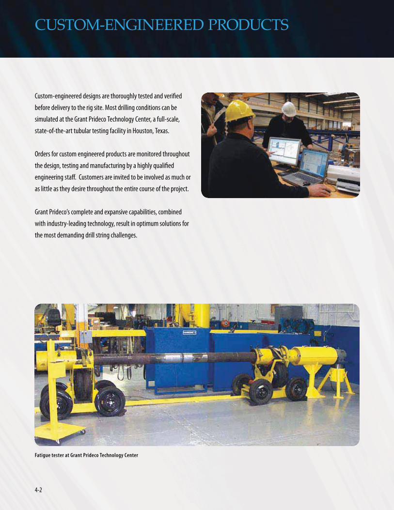
4-2
CUSTOM-ENGINEERED PRODUCTS
Orders for custom engineered products are monitored throughout
as little as they desire throughout the entire course of the project.
with industry-leading technology, result in optimum solutions for
the most demanding drill string challenges.
Fatigue tester at Grant Prideco Technology Center

4-3www.GrantPrideco.com
CUSTOM-ENGINEERED PRODUCTS
Slip-Proof® Drill Pipe
Slip-Proof® Drill Pipe is a Grant Prideco patented product designed
approximately 48 inches long and has minimum yield strength
of 120,000 psi.
Advantages of Slip-Proof® Drill Pipe
Thick-Wall Slip-Proof® pipe is a Grant Prideco patented design to reduce the effect of slip damage and provide improved resistance to slip crushing.
Pipe Body
Slip-Proof® Tube
Tool Joint
Upset

4-4
CUSTOM-ENGINEERED PRODUCTS
Landing Strings
exceed 34,000 feet and extended reach targets push out over
35,000 feet, operators are increasing the setting depths of larger
landing strings with hoisting capacity approaching two million
pounds.
driving the requirement for higher tensile capacity landing strings.
fracture gradient, are causing well designers to set more interme-
diate casing strings. In turn, large diameter, heavy casing strings
are pushed to deeper setting depths in order to maintain hole size
products, Grant Prideco produces superior landing strings to
customer requirements. Landing strings with hoisting capacity
state-of-the-art landing strings address application requirements
elevator capacity.
Reduced tool joint diameter for reduced make-up torque requirements
Extended length, thicker wall slip section for increased slip crushing capacity
Internal and external upset (IEU)
Tungsten carbide free hardbanding to protect riser/casing
SmoothEdge® double diameter box tool joint
Increased tool joint diameter for increased elevator hoisting capacity
High-strength grade tube to reduce wall thickness
Pin wall thickness to provide connection tensile capacity

4-5www.GrantPrideco.com
CUSTOM-ENGINEERED PRODUCTS
Completion Drill Pipe
New design challenges for deepwater, extended reach and other
critical completion operations have limited conventional use of
torsional strength, gas-tight seals and a streamlined connection
with the pressure integrity of a premium connection.
shouldered rotary connections.
15,000 psi internal and 10,000 psi external gas pressures
20,000 psi internal and 10,000 psi external gas pressures
displacing mud with completion fluid, conveying perforating guns
High-performance TurboTorque-M™ (TT-M™) and eXtreme® Torque-M™ (XT-M™) provide the robust configuration of a rotary-shouldered connection with gas-tight pressure integrity for critical completion operations.

4-6
CUSTOM-ENGINEERED PRODUCTS
Drill Pipe Intervention Risers
Offshore well intervention operators have recognized the effective-
ness of utilizing a drill pipe intervention riser in comparison to the
drill pipe intervention riser provides a rugged structure, gas-tight
seal, large internal diameter and corrosion-resistant exterior.
intervention requirements.
the exterior creates an oversized inside diameter throughout the
through the string.
Grant Prideco rotary-shouldered drill pipe connections are rugged
cycles without experiencing galling or other damage. With proper
handling procedures, these connections can complete well over
handling equipment for drill pipe accommodates relatively fast
-
etary sour service drill pipe grades of high yield strength offered
2

HEA
VY
WEIG
HT
DR
ILL PIP
E
HEAVYWEIGHTDRILL PIPE

HEA
VY
WEI
GH
T D
RIL
L P
IPE HEAVYWEIGHT
DRILL PIPE

5-1www.GrantPrideco.com
Grant Prideco offers three types of Heavyweight Drill Pipe
(HWDP). Designed to provide a gradual transition between
drill pipe and drill collars, HWDP improves the fatigue
resistance of the drill string.
Standard HWDP is suited for most applications including vertical,
extended reach and horizontal wells.
Grant Prideco’s Tri-Spiral™ HWDP is suited for applications requiring
additional hole-cleaning and buckling resistance.
Spiral-Wate® HWDP reduces differential sticking, minimizes wear
and improves circulation in especially tough drilling environments.
HEAVYWEIGHT DRILL PIPE

5-2
HEAVYWEIGHT DRILL PIPE
Standard HWDP
Standard Heavyweight Drill Pipe (HWDP), was developed to provide
a gradual transition from heavy drill collars to relatively lightweight
drill pipe. This intermediate weight pipe has a wall thickness of
approximately one inch, and helps prevent stress concentration at
the top of drill collars. HWDP also allows drilling at higher RPMs,
reducing torque and differential pressure sticking.
HWDP is well-suited for directional drilling. Because it bends easily,
it simplifies directional control and minimizes connection fatigue
problems common to high-angle or horizontal drilling.
For extended reach and horizontal wells, especially in wells where
the total vertical depth to total measured depth ratio is low, high
strength heavyweight drill pipe is often used high in the hole to
apply weight on the bit.
Various combinations of HWDP, drill collars and standard drill string
components can be created to meet the challenges of severe
drilling conditions.
24”
DTool Joint OD
BUpset Diameter
ANominal Size
CWear Section
Upset Diameter
BElevator Upset
Diameter
18°
18°
26”
24”
31'Nominal Length
Standard HWDP

5-3www.GrantPrideco.com
HEAVYWEIGHT DRILL PIPE
STANDARD HEAVYWEIGHT DRILL PIPE MECHANICAL PROPERTIES†
Tube Tool Joint Assembly
Nominal DimensionsMechanical Properties
Nominal DimensionsMechanical Properties
Adjusted Weight
NominalSize (A)
ID WallThickness
Area
(sq in)
SectionModules
(cu in)
SpiralUpsets
(C)(in)
EndUpsets
(B)(in)
TensileYield
(lb)
TorsionalYield
(ft-lb)
ConnectionSize and Type
OD(D)
(in)
ID
(in)
TensileYield
(lb)
TorsionalYield
(ft-lb)
PerFoot
Per31 ft Joint (lb)
Make-upTorque
(ft-lb)
2 7/8(1) 1 1/2 0.688 4.727 2.161 3 5/16 2 15/16 520,000 22,400 NC 26 (2 3/8 IF) 3 3/8 1 1/2 357,700 6,300 17.26 535 3,800
3 1/2 2 1/16 0.719 6.282 3.702 4 3 7/8 345,500 19,600 NC 38 (3 1/2 IF) 4 3/4 2 1/16 867,100 19,200 25.65 795 11,500
3 1/2 2 1/4 0.625 5.645 3.490 4 3 7/8 310,500 18,500 NC 38 (3 1/2 IF) 4 3/4 2 1/4 790,900 19,200 23.48 728 11,500
4 2 9/16 0.719 7.411 5.225 4 1/2 4 3/16 407,600 27,600 NC 40 (4 FH) 5 1/4 2 9/16 838,300 27,800 29.92 928 14,600
4 1/2 2 3/4 0.875 9.965 7.698 5 4 11/16 548,100 40,700 NC 46 (4 IF) 6 1/4 2 3/4 1,151,00 43,600 41.45 1,285 22,500
5 3 1.000 12.666 10.681 5 1/2 5 1/8 691,200 56,500 NC 50 (4 1/2 IF) 6 5/8 3 1416,200 57,800 50.38 1,562 30,000
5 1/2 3 1/4 1.125 15.463 14.342 6 5 11/16 850,400 75,900 5 1/2 FH 7 1/4 3 1/4 1,778,300 78,700 61.63 1,911 41,200
HT™55 115,100 69,000*
5 7/8 4 0.938 14.542 15.630 6 3/8 6 799,800 82,700 XT®57 7 4 1,403,100 106,200 57.42 1,780 63,700*
6 5/8 4 1/2 1.063 18.574 22.476 7 1/8 6 15/16 1,021,600 118,900 6 5/8 FH 8 4 1/2 1,896,100 87,900 71.43 2,214 50,500
NOTES: † Please refer to page x of the Introduction. (1) 2-7/8 inch HWDP is only manufactured as an integral (non-welded) design.
CenterUpset

5-4
HEAVYWEIGHT DRILL PIPE
DPin Tool
Joint
CSpiral Upset
C Center Spiral Upset
CSpiral Upset
DBox Tool
Joint
BElevator
Upset Diameter
BUpset
Diameter
ANominal
Size
31'Nominal Length
Tri-Spiral™ HWDP
Grant Prideco developed Tri-Spiral™ Heavyweight Drill Pipe for
extended reach and horizontal drilling applications requiring
greater buckling resistance and hole cleaning than is available with
standard HWDP. The severe bending stresses and hole/wall contact
are reduced by three spiral upsets that are equally spaced between
tool joints. The upset design helps reduce buckling and differential
sticking, as well as torque and drag. Spiraling the upsets also helps
move the cuttings off the low side of the hole for better hole
cleaning.
Tri-Spiral HWDP features more weight per joint and better hole
cleaning characteristics than standard heavyweight drill pipe,
providing optimum performance in severe drilling conditions.
24”
26”
26”
26”
24”
Tri-Spiral™ HWDP

5-5www.GrantPrideco.com
HEAVYWEIGHT DRILL PIPE
TRI-SPIRAL™ HEAVYWEIGHT DRILL PIPE MECHANICAL PROPERTIES†
Tube Tool Joint Assembly
Nominal DimensionsMechanical Properties
Nominal DimensionsMechanical Properties
Adjusted Weight
NominalSize(A)
ID WallThickness
Area
(sq in)
SectionModulus
(cu in)
SpiralUpsets
(C)(in)
EndUpsets
(B)(in)
TensileYield
(lb)
TorsionalYield
(ft-lb)
ConnectionSize and
Type
OD(D)
(in)
ID
(in)
TensileYield
(lb)
TorsionalYield
(ft-lb)
Perfoot
Per 31 ftJoint (lb)
Make-upTorque
(ft-lb)
2 7/8(1) 1 1/2 0.688 4.727 2.161 3 5/16 2 15/16 520,000 22,900 NC 26 (2 3/8 IF) 3 3/8 1 1/2 357,700 6,300 18.22 565 3,800
3 1/2 2 1/16 0.719 6.282 3.702 4 3 7/8 345,500 19,600 NC 38 (3 1/2 IF) 4 3/4 2 1/16 867,100 19,200 27.05 839 11,500
3 1/2 2 1/4 0.625 5.645 3.490 4 3 7/8 310,500 18,500 NC 38 (3 1/2 IF) 4 3/4 2 1/4 790,900 19,200 24.88 771 11,500
4 2 9/16 0.719 7.411 5.225 4 1/2 4 3/16 407,600 27,600 NC 40 (4 FH) 5 1/4 2 9/16 838,300 27,800 31.51 977 14,600
4 1/2 2 3/4 0.875 9.965 7.698 5 4 11/16 548,100 40,700 NC 46 (4 IF) 6 1/4 2 3/4 1,151,100 43,600 43.31 1,343 22,500
5 3 1.000 12.566 10.681 5 1/2 5 1/8 691,200 56,500 NC 50 (4 1/2 IF) 6 5/8 3 1,416,200 57,800 52.34 1,623 30,000
5 1/2 3 1/4 1.125 15.463 14.342 6 5 11/16 850,400 75,900 5 1/2 FH 7 1/4 3 1/4 1,778,300 78,700 63.78 1,977 41,200
5 7/8 4 0.938 14.542 15.630 6 3/8 6 799,800 82,700 XT®57 7 4 1,403,100 106,200 57.42 1,780 63,700*
6 5/8 4 1/2 1.063 18.574 22.476 7 1/8 6 15/16 1,021,600 118,850 6 5/8 FH 8 4 1/2 1,896,100 87,900 74.67 2,315 50,500
NOTES: † Please refer to page x of the Introduction. (1) 2-7/8 inch Tri-Spiral is only manufactured as an integral (non-welded) design.

5-6
HEAVYWEIGHT DRILL PIPE
Spiral-Wate® HWDP
Spiral-Wate® drill pipe, spiraled heavy-wall drill pipe, is designed to
handle maximum stress to save time and reduce drilling costs,
especially in tough drilling environments.
Intermediate drill string members are constantly subjected to some
of the most severe tasks in drilling today. The critical transition
zone between stiff, heavy drill collars (under compression) and
the light, more flexible drill pipe (in tension) is critical to the
performance of the drill string.
Spiral-Wate drill pipe’s unique patented spiral design reduces
differential sticking problems, minimizes wear and improves
circulation. Precision tool joint alignment cuts down on excessive
tool joint wear for longer service life and reduced fatigue.
31'Nominal Length
24”
DBox Tool
Joint
BElevator Upset
Diameter
CSpiral Upset
ANominal
Size
DPin Tool
Joint
42”
21'4”
9”
24”
Spiral-Wate® HWDP

5-7www.GrantPrideco.com
HEAVYWEIGHT DRILL PIPE
SPIRAL-WATE® DRILL PIPE MECHANICAL PROPERTIES†
Tube Tool Joint Assembly
Nominal DimensionsMechanical Properties
Nominal DimensionsMechanical Properties
Adjusted Weight
NominalSize
ID
(A)
WallThickness
Area
(sq in)
SectionModulus
(cu in)
SpiralUpsets
(C)(in)
Box EndUpset
(B)(in)
TensileYield
(lb)
TorsionalYield
(ft-lb)
ConnectionSize and
Type
OD(D)
(in)
ID
(in)
TensileYield
(lb)
TorsionalYield
(ft-lb)
Perfoot
Per 31 ftJoint (lb)
Make-upTorque
(ft-lb)
3 3/16(1) 2 0.594 4.840 2.687 5 5/16 Nominal 532,400 28,400 SLH90 3 7/8 2 407,000 12,000 19.48 604 6,300
3 1/2 2 1/4 0.625 5.645 3.490 4 3 5/8 310,500 18,500 NC 38 (3 1/2 IF) 4 7/8 2 1/4 790,000 22,900 30.39 942 13,100
4 2 9/16 0.719 7.411 5.225 4 1/2 4 1/8 407,600 27,600 NC 40 (4 FH) 5 2 9/16 838,300 20,900 28.90 896 12,600
XT39 729,700 40,800 24,500(2)
4 1/2 2 3/4 0.875 9.965 7.698 5 4 5/8 548,100 40,700 NC 46 (4 IF) 6 1/4 2 3/4 1,183,900 44,900 49.53 1,535 23,200
5 3 1.000 12.566 10.681 5 1/2 5 1/8 691,200 56,500 NC 50 (4 1/2 IF) 6 5/8 3 1,416,200 57,800 59.16 1,834 30,000
HT50 88,800 53,300 (2)
5 1/2 4 0.750 11.192 11.764 6 5 5/8 615,600 62,200 5 1/2 FH 7 4 1,265,800 56,000 54.57 29,200
HT55® 77,200 46,300 (2)
5 7/8 4 0.938 14.542 16.630 6 3/8 6 799,800 82,700 XT57® 7 4 1,403,100 106,200 65.38 2,027 63,700 (2)
6 5/8 4 1/2 1.063 18.574 22.476 7 1/8 6 3/4 1,021,600 118,900 6 5/8 FH 8 4 1/2 1,896,100 88,000 82.12 50,500
NOTES: † Please refer to page x of the Introduction. (1) 3-3/16 inch Spiral-Wate, previously referred to as 2-7/8 inch, is only manufactured as an integral (non-welded) design. (2) Reduced makeup for typically chamfered connection.

5-8
Features and Options
Extra-Long Tool Joints
Grant Prideco heavyweight drill pipe is manufactured by welding
extra-long tool joints to heavy-wall tubes. The extra-long tool joint
increases tong space, and allows for several connection recuts to
maximize your investment.
Cold Rolling
Heavyweight drill pipe undergoes repeated severe tensile and
compressive stresses during the drilling operation. As compared to
regular drill pipe, HWDP is much stiffer, focusing cyclic stresses on
the thread roots and potentially resulting in connection failure. To
help alleviate this problem, the thread roots on every piece of
heavyweight drill pipe are cold-rolled by Grant Prideco. Cold rolling
imparts an initial state of compressive stress that minimizes crack
initiation thereby increasing fatigue resistance.
HEAVYWEIGHT DRILL PIPE
Phosphate Coating
All heavyweight drill pipe connections are given a hot phosphate
coating to provide resistance to galling and corrosion.
Hardbanding
Grant Prideco has several hardbanding materials available to apply
to heavyweight drill pipe including Platinum® HB and SmoothX™,
as well as third-party materials. Hardbanding can be applied in
several configurations to meet specific needs.
Proprietary Rotary-Shouldered Connections
In addition to the API and public domain connections listed in the
previous tables, Grant Prideco can provide heavyweight drill pipe
with proprietary stress relief thread forms or double-shouldered
connections to enhance performance (see Rotary-Shouldered
Connections section).
The cold-rolling process consists of compressing metal fibers by means of a roller to increase fatigue resistance.

5-9www.GrantPrideco.com
HEAVYWEIGHT DRILL PIPE
HWDP Grades
Standard Heavyweight Drill Pipe
Grant Prideco standard heavyweight pipe is manufactured from
AISI 1340 material and heavyweight tool joints are manufactured
from AISI 4142H-4145H modified drill collar material.
eXtreme® Drilling XD®-90 Sour Service Grade
eXtreme® XD®-90 HWDP is a proprietary product offered by Grant
Prideco for service in H2S environments. Available in both standard
and spiral designs, XD-90 heavyweight drill pipe provides higher
strength and a tempered martensite microstructure for enhanced
resistance to crack initiation and crack propagation. XD-90 HWDP
incorporates a proprietary chemistry and a rigidly controlled
quench-and-temper heat treatment process. The eXtreme XD-90 is
resistant to sulfide stress cracking and its high fracture toughness
is ideal for the most demanding drilling conditions, including
applications with high bending loads and corrosive environments.

5-10
HEAVYWEIGHT DRILL PIPE
HEAVYWEIGHT DRILL PIPE MATERIAL GRADES†
MaterialsMechanical Properties
YieldStrength
MinimumTensile
StrengthHardness
(ksi) (ksi)
Standard HWDP
Tube 55 Min 95 285 HBN Max
Tool Joint 120 Min 140 285-341 HBN
Weld-Line – – 36 HRC Max
HW™-95
Tube 95 Min 105 26 HRC Max
Tool Joint 120 Min 140 285-341 HBN
Weld-Line – – 36 HRC Max
XD®-90
Tube 90-105 100 22 HRC Max
Tool Joint 100-115 120 28 HRC Max
Weld-Line – – 28 HRC Max
HW™-120
Tube 120 Min 130 285 HBN Max
Tool Joint 120 Min 140 285-341 HBN
Weld-Line – – 36 HRC Max
5 INCH HWDP TUBE MECHANICAL PROPERTIES†
Grade Standard XD®-90 HW-95
Torsional Strength (ft-lbs) 56,500 92,400 97,600
Tensile Strength (lbs) 691,200 1,131,000 1,193,000
eXtreme® HW™-95 and HW™-120 Heavyweight Drill Pipe
HWTM-95 and HWTM-120 high-strength heavyweight drill pipe are
proprietary grades offered by Grant Prideco for target applications
requiring the use of HWDP high in the hole where elevated tensile
and torsional loading is expected. Both HW-95 and HW-120 provide
high yield strength – 95 ksi and 120 ksi minimum, respectively,
a 73% and 218% increase in yield strength over standard
heavyweight products – resulting in superior tensile and torsional
strength properties. These pipe configurations provide tensile and
torsional capacities equal to or greater than nearly all types of
standard API drill pipes tubes. As a result of the increased strength,
HW-95 and HW-120 are a perfect fit for applications such as short
radius, horizontal and extended reach drilling projects where use of
HWDP above the kick-off point is required for applying bit weight
and additional buckling stability.
NOTES: † Please refer to page x of the Introduction.

DR
ILL COLLA
RS &
DR
ILL STEM
ACCESSO
RIES
DRILL COLLARS & DRILL STEM ACCESSORIES

DR
ILL
COLL
AR
S &
DR
ILL
STEM
ACC
ESSO
RIE
S
DRILL COLLARS & DRILL STEM ACCESSORIES
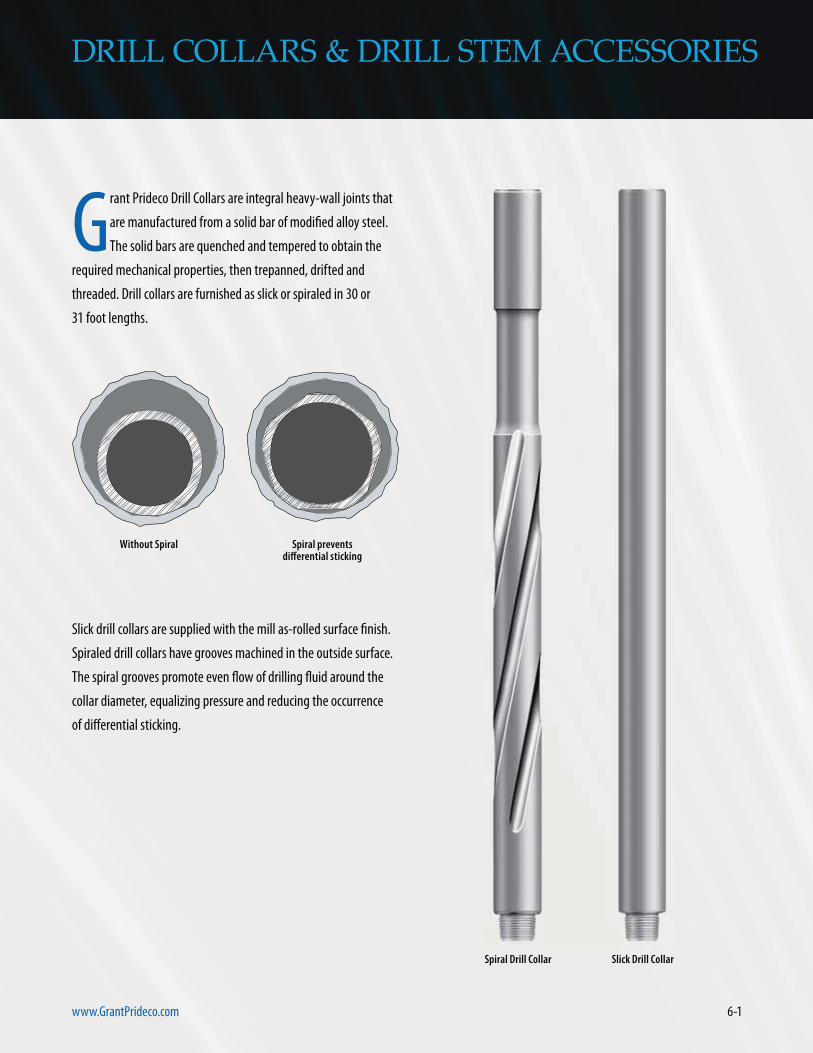
6-1www.GrantPrideco.com
DRILL COLLARS & DRILL STEM ACCESSORIES
Grant Prideco Drill Collars are integral heavy-wall joints that
are manufactured from a solid bar of modified alloy steel.
The solid bars are quenched and tempered to obtain the
required mechanical properties, then trepanned, drifted and
threaded. Drill collars are furnished as slick or spiraled in 30 or
31 foot lengths.
Slick drill collars are supplied with the mill as-rolled surface finish.
Spiraled drill collars have grooves machined in the outside surface.
The spiral grooves promote even flow of drilling fluid around the
collar diameter, equalizing pressure and reducing the occurrence
of differential sticking.
Without Spiral
Spiral Drill Collar
Spiral prevents differential sticking
Slick Drill Collar

6-2
DRILL COLLARS & DRILL STEM ACCESSORIES
Pony Collars
In order to adjust the length and control the placement of
components in bottom-hole assembly, Grant Prideco can provide
pony collars in 5, 10, 15 and 20 foot lengths. Pony collars can be
furnished in standard or non-magnetic material, and can be
customized to suit individual requirements with any of the
options offered for full-length collars.
Drill CollarNumber(1)
Drill CollarDiameter
Bore+ 1/16"-0"
Length ApproximateWeight
SectionModulus
Displacement(open ended)
Typical BendingStrength
Ratio
in in ft lb/ft in3 US gal/ft
NC 23-31 3 1/8 1 1/4 30 22.00 2.919 0.337 2.57:1
NC 26-35 (2 3/8 IF) 3 1/2 1 1/2 30 26.70 4.067 0.408 2.42:1
NC 31-41 (2 7/8 IF) 4 1/8 2 30 or 31 34.72 6.510 0.531 2.43:1
NC 35-47 4 3/4 2 30 or 31 44.51 10.191 0.757 2.58:1
NC 38-50 (3 1/2 IF) 5 2 1/4 30 or 31 53.18 11.769 0.815 2.38:1
NC 44-60 6 2 1/4 30 or 31 82.61 20.786 1.264 2.49:1
NC 44-60 6 2 13/16 30 or 31 74.90 20.182 1.146 2.84:1
NC 44-62 6 1/4 2 1/4 30 or 31 90.52 23.566 1.385 2.91:1
NC 46-62 (4 IF) 6 1/4 2 13/16 30 or 31 83.09 22.986 1.271 2.63:1
NC 46-65 (4 IF) 6 1/2 2 1/4 30 or 31 99.19 26.574 1.522 2.76:1
NC 46-65 (4 IF) 6 1/2 2 13/16 30 or 31 91.59 26.016 1.401 3.05:1
NC 46-67 (4 IF) 6 3/4 2 1/4 30 or 31 108.02 29.821 1.652 3.18:1
NC 50-70 (4 1/2 IF) 7 2 1/4 30 or 31 117.52 33.315 1.798 2.54:1
NC 50-70 (4 1/2 IF) 7 2 13/16 30 or 31 109.60 32.796 1.676 2.73:1
NC 50-72 (4 1/2 IF) 7 1/4 2 13/16 30 or 31 119.10 36.565 1.822 3.12:1
NC 56-77 7 3/4 2 13/16 30 or 31 139.10 44.906 2.140 2.70:1
NC 56-80 8 2 13/16 30 or 31 149.60 49.498 2.307 3.02:1
6 5/8 API Reg 8 1/4 2 13/16 30 or 31 160.44 54.382 2.472 2.93:1
NC 61-90 9 2 13/16 30 or 31 194.95 70.887 2.995 3.17:1
7 5/8 API Reg 9 1/2 3 30 or 31 217.00 83.336 3.319 2.81:1
NC 70-97 9 3/4 3 30 or 31 230.00 90.179 3.518 2.57:1
NC 70-100 10 3 30 or 31 242.97 97.380 3.717 2.81:1
8 5/8 API Reg 11 3 30 or 31 299.00 129.948 4.574 2.84:1
NOTES: † Please refer to page x of the Introduction. (1) The Number Connection (NC) is an API connection with the V- .065 thread form and a V- .038R thread root radius. The first two digits are the pitch diameter of the thread and the last two digits are the outside diameter of the drill collar.
DRILL COLLAR DATA†

6-3www.GrantPrideco.com
DRILL COLLARS & DRILL STEM ACCESSORIES
SLIP AND ELEVATOR RECESSES†
Drill CollarDiameter
Elevator Recess
Diameter
SlipRecess
Diameter
ElevatorRecessRadius
A B C R
in in in in
4 1/8(1) 3 11/16 3 3/4 1/8
4 3/4 4 1/4 4 3/8 1/8
5 4 1/2 4 5/8 1/8
6 5 3/8 5 1/2 1/8
6 1/4 5 5/8 5 3/4 1/8
6 1/2 5 7/8 6 1/8
6 3/4 6 6 1/4 3/16
7 6 1/4 6 1/2 3/16
7 1/4 6 1/2 6 3/4 3/16
7 3/4 7 7 1/4 3/16
8 7 1/4 7 1/2 3/16
8 1/4 7 1/2 7 3/4 3/16
9 8 1/8 8 1/2 1/4
9 1/2 8 5/8 9 1/4
9 3/4 8 7/8 9 1/4 1/4
10 9 1/8 9 1/2 1/4
11 10 1/8 10 1/2 1/4
3”
RCold WorkShoulder
Area
1” Radius
Shoulder Area
A
B
2” Radius
C
3”
3”
16”
18”
20”
C
B
A
Slip and Elevator Recesses
Grant Prideco offers optional slip and elevator recesses to improve
handling efficiency and safety. The upper radius of the elevator
recess is cold-rolled to increase product life. Slip and elevator
recesses can be used together or separately. Unless otherwise
specified, slip and elevator recesses are machined in compliance
with API RP7G Latest Edition guidelines.
2” Radius
NOTES: † Please refer to page x of the Introduction. (1) These features are not recommended for collars with an OD below 4-3/4 inches.

6-4
DRILL COLLAR MATERIAL GRADES†
OD(in)
MaterialSpecification
MinimumYield
Strength(psi)
MinimumTensile
Strength(psi)
Elongation(%)
MinimumCharpy(1)
(ft-lb)
MinimumHardness
(BHN)
3 1/8 to 6 7/8
AISI 4145 HModified
110,000 140,000 13 40 285
7 to 11AISI 4145 H
Modified110,000 135,000 13 40 285
3 1/8 to 6 7/8
Stainless 110,000 120,000 18 — —
7 to 11 Stainless 100,000 110,000 20 — —
NOTES: † Please refer to page x of the Introduction. (1) The Charpy impact strength of 40 ft-lbs minimum is for a full-size specimen from one inch below the surface at 70ºF.
Drill Collar Material
The following chart outlines various material grades used for
different drill collar sizes.
DRILL COLLARS & DRILL STEM ACCESSORIES

6-5www.GrantPrideco.com
Size and Type(3)
of Connection
Drill Collar Bore (in)
OD 1 1 1/4 1 1/2 1 3/4 2 2 1/4 2 1/2 2 13/16
in ft-lb(1,2) BSR ft-lb(1,2) BSR ft-lb(1,2) BSR ft-lb(1,2) BSR ft-lb(1,2) BSR ft-lb(1,2) BSR ft-lb(1,2) BSR ft-lb(1,2) BSR
API NC 23
3 2,500 2.03 2,500 2.17 2,500 2.49
3 1/8 3,300 2.40 3,300 2.57 2,600 2.94
3 1/4 4,000 2.81 3,400 3.00 2,600 3.43
2 3/8 Regular
3 2,200 2.36 2,200 2.70 1,700 3.53
3 1/8 3,000 2.75 2,600 3.14 1,700 4.10
3 1/4 3,300 3.17 2,600 3.62 1,700 4.72
2 7/8 PAC(6)
3 3,800 1.81 3,800 2.01 2,900 2.53
3 1/8 5,000 2.18 4,200 2.43 2,900 3.07
3 1/4 5,200 2.57 4,200 2.88 2,900 3.63
2 3/8 IFAPI NC 262 7/8 Slim Hole
– – – – – –
3 1/2 4,600 2.25 4,600 2.42 3,700 2.76
3 3/4 5,500 2.96 4,700 3.18 3,700 3.64
2 7/8 Regular
3 1/2 3,800 2.27 3,800 2.42 3,800 2.73
3 3/4 5,800 2.91 5,000 3.10 4,000 3.49
3 7/8 5,800 3.26 5,000 3.48 4,000 3.91
2 7/8 XH3 1/2 Dbl Streamline2 7/8 Mod. Open
3 3/4 4,100 1.53 4,100 1.60 4,100 1.70
3 7/8 5,400 1.76 5,400 1.82 5,400 1.93
4 1/8 8,100 2.26 8,100 2.34 7,400 2.53
2 7/8 IFNC 313 1/2 Slim Hole
3 7/8 4,600 1.54 4,600 1.59 4,600 1.69 4,600 1.85 – –
4 1/8 7,400 2.03 7,400 2.10 7,400 2.22 6,900 2.44 – –
4 1/4 8,900 2.29 8,900 2.37 8,200 2.51 6,900 2.75 5,400 3.21
4 1/2 10,300 2.86 9,300 2.95 8,200 3.13 6,900 3.43 5,400 4.01
3 1/2 Regular
4 1/8 6,500 2.09 6,500 2.16 6,500 2.27 6,500 2.48 5,700 2.85
4 1/4 7,900 2.34 7,900 2.41 7,900 2.54 7,100 2.77 5,700 3.18
4 1/2 10,500 2.86 9,500 2.95 8,400 3.11 7,100 3.39 5,700 3.90
NC 35
4 1/2 9,000 1.95 9,000 2.07 9,000 2.26 7,400 2.59
4 3/4 12,300 2.44 10,800 2.58 9,200 2.82 7,400 3.24
5 12,300 2.97 10,800 3.14 9,200 3.43 7,400 3.95
3 1/2 XH4 Slim Hole3 1/2 Mod. Open
4 1/4 5,200 1.31 5,200 1.37 5,200 1.48 5,200 1.68
4 1/2 8,500 1.71 8,500 1.80 8,500 1.95 8,300 2.20
4 3/4 12,100 2.16 11,800 2.27 10,100 2.46 8,300 2.83
5 13,300 2.65 11,800 2.79 10,100 3.06 8,300 3.47
5 1/4 13,300 3.23 11,800 3.40 10,100 3.69 8,300 4.18
3 1/2 IFNC 384 1/2 Slim Hole
4 3/4 10,000 1.73 10,000 1.80 10,000 1.92 10,000 2.10 8,300 2.54
5 13,900 2.15 13,900 2.24 12,900 2.38 11,000 2.61 8,300 3.15
5 1/4 16,200 2.61 14,600 2.71 12,900 2.88 11,000 3.17 8,300 3.82
5 1/2 16,200 3.10 14,600 3.23 12,900 3.43 11,000 3.77 8,300 4.54
RECOMMENDED MAKE-UP TORQUE AND BENDING STRENGTH RATIOS†
NOTES: † Please refer to page x of the Introduction. (1) Basis of calculations for recommended make-up torque assumed the use of a thread compound containing 40% to 60% by weight of finely powdered metallic zinc, or 60% by weight of finely powdered metallic lead, with no more than 0.3% total active sulfur (reference the caution regarding the use of hazardous materials in Appendix G API Spec. 7 Latest Edition), applied thoroughly to all threads and shoulders. Also, the modified screw jack formula was used, as shown in the IADC Drilling Manual and the API Spec. RP7G Latest Edition and a unit stress of 62,500 psi in the box or pin, whichever is weaker. Torque values are rounded to the nearest 100 ft-lb. (2) Normal torque range is calculated value plus 10%. Higher torque values may be used under extreme conditions.
DRILL COLLARS & DRILL STEM ACCESSORIES

6-6
DRILL COLLARS & DRILL STEM ACCESSORIES
Size and Type (3)
of Connection
Drill Collar Bore (in)
OD 1 3/4 2 2 1/4 2 1/2 2 13/16 3 3 1/4
in ft-lb(1,2) BSR ft-lb(1,2) BSR ft-lb(1,2) BSR ft-lb(1,2) BSR ft-lb(1,2) BSR ft-lb(1,2) BSR ft-lb(1,2) BSR
3 1/2 H-90(5)
4 3/4 8,800 1.46 8,800 1.51 8,800 1.59 8,800 1.71 8,800 1.99
5 12,800 1.83 12,800 1.89 12,800 1.99 12,800 2.15 10,400 2.49
5 1/4 17,100 2.23 16,900 2.31 15,100 2.43 13,200 2.62 10,400 3.04
5 1/2 18,500 2.67 16,900 2.76 15,100 2.91 13,200 3.14 10,400 3.64
4 Full HoleNC 404 Mod. Open4 1/2 Dbl. Streamline
5 10,900 1.61 10,900 1.66 10,900 1.74 10,900 1.86 10,900 2.11
5 1/4 15,300 1.98 15,300 2.04 15,300 2.14 15,000 2.29 12,100 2.60
5 1/2 20,000 2.38 18,900 2.46 17,000 2.57 15,000 2.75 12,100 3.12
5 3/4 20,500 2.82 18,900 2.91 17,000 3.04 15,000 3.25 12,100 3.70
6 20,500 3.29 18,900 3.39 17,000 3.55 15,000 3.79 12,100 4.31
4 H-90(5)
5 1/4 12,600 1.47 12,600 1.51 12,600 1.56 12,600 1.64 12,600 1.80
5 1/2 17,400 1.80 17,400 1.85 17,400 1.91 17,400 2.01 16,500 2.20
5 3/4 22,500 2.17 22,500 2.22 21,700 2.29 19,500 2.41 16,500 2.66
6 25,400 2.55 23,700 2.61 21,700 2.70 19,500 2.84 16,500 3.12
6 1/4 25,400 2.97 23,700 3.04 21,700 3.15 19,500 3.31 16,500 3.63
4 1/2 API Regular
5 1/2 15,600 1.89 15,600 1.94 15,600 2.00 15,600 2.10 15,600 2.30
5 3/4 20,600 2.24 20,600 2.29 20,600 2.37 19,600 2.49 16,600 2.72
6 25,400 2.62 23,700 2.65 21,700 2.77 19,600 2.91 16,600 3.18
6 1/4 25,400 3.02 23,700 3.09 21,700 3.20 19,600 3.35 16,600 3.67
NC 44
5 3/4 20,900 1.99 20,900 2.04 20,900 2.10 20,900 2.20 18,200 2.39
6 26,500 2.36 25,500 2.41 23,500 2.49 21,300 2.61 18,200 2.84
6 1/4 27,300 2.76 25,500 2.82 23,500 2.91 21,300 3.04 18,200 3.31
6 1/2 27,300 3.19 25,500 3.25 23,500 3.36 21,300 3.51 18,200 3.82
4 1/2 FH
5 1/2 13,000 1.60 13,000 1.65 13,000 1.71 13,000 1.85 13,000 1.93
5 3/4 18,100 1.92 18,100 1.97 18,100 2.06 18,100 2.22 17,900 2.36
6 23,600 2.28 23,600 2.33 23,000 2.42 19,900 2.61 17,900 2.76
6 1/4 27,300 2.64 25,300 2.71 23,000 2.82 19,900 3.04 17,900 3.24
6 1/2 27,300 3.03 25,300 3.12 23,000 3.25 19,900 3.50 17,900 3.73
4 1/2 XHNC 464 IF5 Dbl. Streamline4 1/2 Mod. Open
5 3/4 17,700 1.68 17,700 1.74 17,700 1.87 17,700 1.97
6 23,400 2.02 23,400 2.09 22,400 2.24 20,300 2.37
6 1/4 28,000 2.38 25,700 2.47 22,400 2.64 20,300 2.79
6 1/2 28,000 2.77 25,700 2.87 22,400 3.07 20,300 3.25
6 3/4 28,000 3.18 25,700 3.30 22,400 3.57 20,300 3.74
4 1/2 H-90(5)
5 3/4 18,000 1.64 18,000 1.69 18,000 1.80 18,000 1.90
6 23,700 1.95 23,700 2.02 23,200 2.16 21,100 2.28
6 1/4 28,700 2.30 26,400 2.38 23,200 2.54 21,100 2.69
6 1/2 28,700 2.69 26,400 2.77 23,200 2.96 21,100 3.12
6 3/4 28,700 3.08 26,400 3.19 23,200 3.40 21,100 3.59
5 H-90 (5)
6 1/4 25,400 1.80 25,400 1.85 25,400 1.95 25,400 2.03 24,000 2.18
6 1/2 31,900 2.12 31,900 2.17 29,400 2.29 27,200 2.38 24,000 2.56
6 3/4 35,300 2.45 32,800 2.52 29,400 2.65 27,200 2.76 24,000 2.97
7 35,300 2.82 32,800 2.90 29,400 3.05 27,200 3.18 24,000 3.41
NOTES (cont'd): (3) In each connection size and type group torque values apply to all connection types in the group, when used with the same drill collar OD and bore, i.e. 2-3/8 API IF, API NC26 and 2-7/8 Slim Hole connections, used with 3-1/2 x 1-1/4 drill collars, all have the same minimum make-up torque of 4600 ft-lbs and the box is the weaker member. (4) Stress-relief features are disregarded for make up torque calculation. (5) H-90 connection make-up torque is based on 56,200 psi stress and other factors, as listed in note 7. (6) 2-7/8 PAC make-up torque is based on 87,500 psi stress and other factors, as listed in note 7. (7) Torque figures in bold indicate that the weaker member for the corresponding outside diameter and bore is the box. For all other torque values, the weaker member is the pin.
RECOMMENDED MAKE-UP TORQUE AND BENDING STRENGTH RATIOS† (continued)

6-7www.GrantPrideco.com
DRILL COLLARS & DRILL STEM ACCESSORIES
RECOMMENDED MAKE-UP TORQUE AND BENDING STRENGTH RATIOS† (continued)
Size and Type (3)
of Connection
Drill Collar Bore (in)
OD 2 1/4 2 1/2 2 13/16 3 3 1/4 3 1/2 3 3/4
in ft-lb(1,2) BSR ft-lb(1,2) BSR ft-lb(1,2) BSR ft-lb(1,2) BSR ft-lb(1,2) BSR ft-lb(1,2) BSR lb/ft(1,2) BSR
4 1/2 IFAPI NC 505 XH5 Mod. Open5 1/2 Dbl. Streamline
6 1/4 23,000 1.59 23,000 1.63 23,000 1.71 23,000 1.77 23,000 1.89
6 1/2 29,700 1.89 29,700 1.93 29,700 2.03 29,700 2.10 26,700 2.24
6 3/4 36,700 2.21 35,800 2.26 32,300 2.37 30,000 2.46 26,700 2.62
7 38,400 2.54 35,800 2.61 32,300 2.73 30,000 2.83 26,700 3.02
7 1/4 38,400 2.91 35,800 2.98 32,300 3.12 30,000 3.24 26,700 3.45
7 1/2 38,400 3.29 35,800 3.38 32,300 3.53 30,000 3.67 26,700 3.91
5 1/2 H-90 (5)
6 3/4 34,500 1.94 34,500 1.98 34,500 2.06 34,100 2.13 30,800 2.25
7 42,000 2.25 40,100 2.30 36,500 2.39 34,100 2.46 30,800 2.60
7 1/4 42,700 2.57 40,100 2.63 36,500 2.73 34,100 2.82 30,800 2.98
7 1/2 42,700 2.92 40,100 2.98 36,500 3.10 34,100 3.20 30,800 3.38
5 1/2 API Regular
6 3/4 31,900 2.07 31,900 2.11 31,900 2.20 31,900 2.27 30,500 2.40
7 39,400 2.37 39,400 2.42 36,200 2.52 33,900 2.60 30,500 2.75
7 1/4 42,500 2.70 39,900 2.76 36,200 2.87 33,900 2.96 30,500 3.13
7 1/2 42,500 3.04 39,900 3.11 36,200 3.23 33,900 3.34 30,500 3.53
5 1/2 API FH
7 32,800 1.64 32,800 1.67 32,800 1.72 32,800 1.76 32,800 1.83
7 1/4 41,000 1.91 41,000 1.95 41,000 2.00 41,000 2.05 41,000 2.14
7 1/2 49,700 2.20 49,700 2.24 47,800 2.30 45,200 2.36 41,500 2.45
7 3/4 54,500 2.50 51,700 2.54 47,800 2.62 45,200 2.68 41,500 2.79
NC 56
7 1/4 40,500 2.05 40,500 2.11 40,500 2.16 40,500 2.24
7 1/2 49,100 2.33 48,200 2.39 45,600 2.45 42,100 2.55
7 3/4 52,100 2.62 48,200 2.70 45,600 2.76 42,100 2.87
8 52,100 2.94 48,200 3.02 45,600 3.09 42,100 3.21
6 5/8 API Regular
7 1/2 46,400 1.96 46,400 2.01 46,400 2.05 46,400 2.12
7 3/4 55,600 2.24 53,300 2.30 50,700 2.35 46,900 2.43
8 57,400 2.54 53,300 2.60 50,700 2.66 46,900 2.75
8 1/4 57,400 2.85 53,300 2.93 50,700 2.99 46,900 3.10
6 5/8 H-90(5)
7 1/2 46,500 1.84 46,500 1.89 46,500 1.92 46,500 1.99
7 3/4 55,700 2.11 55,700 2.16 53,600 2.20 49,900 2.27
8 60,300 2.39 56,300 2.45 53,600 2.49 49,900 2.58
8 1/4 60,300 2.69 56,300 2.75 53,600 2.80 49,900 2.90
NC 61
8 55,100 2.03 55,100 2.07 55,100 2.10 55,100 2.16
8 1/4 65,400 2.28 65,400 2.32 65,400 2.36 61,600 2.42
8 1/2 72,700 2.54 68,400 2.59 65,600 2.63 61,600 2.70
8 3/4 72,700 2.82 68,400 2.87 65,600 2.92 61,600 2.99
9 72,700 3.11 68,400 3.17 65,600 3.22 61,600 3.30
5 1/2 IF
8 56,600 1.82 56,600 1.85 56,600 1.88 56,600 1.93 56,600 1.99
8 1/4 67,100 2.07 67,100 2.11 67,100 2.14 63,400 2.19 59,000 2.26
8 1/2 74,600 2.33 70,300 2.37 67,400 2.41 63,400 2.47 59,000 2.55
8 3/4 74,600 2.60 70,300 2.65 67,400 2.69 63,400 2.76 59,000 2.85
9 74,600 2.89 70,300 2.95 67,400 2.99 63,400 3.06 59,000 3.16
9 1/4 74,600 3.20 70,300 3.26 67,400 3.30 63,400 3.39 59,000 3.50
6 5/8 FH
8 1/2 67,800 1.88 67,800 1.91 67,800 1.93 67,800 1.97 67,800 2.02 67,200 2.09
8 3/4 79,500 2.12 79,500 2.15 79,500 2.18 76,700 2.23 72,100 2.28 67,200 2.36
9 88,600 2.38 84,000 2.41 81,000 2.44 76,700 2.49 72,100 2.56 67,200 2.64
9 1/4 88,600 2.64 84,000 2.68 81,000 2.72 76,700 2.77 72,100 2.85 67,200 2.94
9 1/2 88,600 2.92 84,000 2.97 81,000 3.00 76,700 3.07 72,100 3.15 67,200 3.25
NOTES (cont'd): † Please refer to page x of the Introduction.

6-8
DRILL COLLARS & DRILL STEM ACCESSORIES
RECOMMENDED MAKE-UP TORQUE AND BENDING STRENGTH RATIOS† (continued)
Size and Type (3)
of Connection
Drill Collar Bore (in)
OD 2 1/2 2 13/16 3 3 1/4 3 1/2 3 3/4
in ft-lb(1,2) BSR ft-lb(1,2) BSR ft-lb(1,2) BSR ft-lb(1,2) BSR ft-lb(1,2) BSR ft-lb(1,2) BSR
NC 70
9 75,800 1.87 75,800 1.89 75,800 1.91 75,800 1.93 75,800 1.97 75,800 2.02
9 1/4 88,800 2.08 88,800 2.10 88,800 2.12 88,800 2.15 88,800 2.19 88,800 2.24
9 1/2 102,400 2.29 102,400 2.32 102,400 2.34 101,100 2.37 96,200 2.41 91,000 2.47
9 3/4 113,700 2.52 108,800 2.55 105,700 2.57 101,100 2.60 96,200 2.65 91,000 2.71
10 113,700 2.76 108,800 2.79 105,700 2.81 101,100 2.85 96,200 2.90 91,000 2.97
10 1/4 113,700 3.01 108,800 3.04 105,700 3.06 101,100 3.11 96,200 3.17 91,000 3.24
NC 77
10 108,200 1.94 108,200 1.95 108,200 1.96 108,200 1.98 108,200 2.01 108,200 2.04
10 1/4 124,100 2.13 124,100 2.14 124,100 2.16 124,100 2.10 124,100 2.20 124,100 2.24
10 1/2 140,500 2.33 140,500 2.34 140,500 2.36 140,500 2.38 135,100 2.41 129,400 2.44
10 3/4 154,300 2.53 149,000 2.55 145,500 2.56 140,500 2.59 135,100 2.62 129,400 2.66
11 154,300 2.75 149,000 2.77 145,500 2.78 140,500 2.81 135,100 2.84 129,400 2.89
Connections with Full Faces
7 H-90(5)
8 53,500 1.90 53,500 1.94 53,500 1.96 53,500 2.01 53,500 2.07 53,500 2.16
8 1/4 63,700 2.14 63,700 2.18 63,700 2.21 63,700 2.26 61,000 2.33 56,400 2.42
8 1/2 74,500 2.39 72,100 2.43 69,300 2.46 65,300 2.52 61,000 2.60 56,400 2.70
7 5/8 API Regular
8 1/2 60,400 1.80 60,400 1.83 60,400 1.84 60,400 1.88 60,400 1.92 60,400 1.98
8 3/4 72,200 2.02 72,200 2.05 72,200 2.07 72,200 2.11 72,200 2.16 72,200 2.22
9 84,400 2.25 84,400 2.28 84,400 2.31 84,200 2.35 79,500 2.40 74,500 2.47
9 1/4 96,300 2.49 91,600 2.53 88,600 2.55 84,200 2.60 79,500 2.66 74,500 2.74
9 1/2 96,300 2.75 91,600 2.78 88,600 2.81 84,200 2.87 79,500 2.93 74,500 3.02
7 5/8 H-90(5)
9 73,000 1.76 73,000 1.78 73,000 1.79 73,000 1.81 73,000 1.84 73,000 1.88
9 1/4 86,000 1.95 86,000 1.97 86,000 1.99 86,000 2.02 86,000 2.05 86,000 2.09
9 1/2 99,500 2.16 99,500 2.18 99,500 2.20 99,500 2.23 99,500 2.27 96,300 2.31
8 5/8 API Regular
10 109,300 1.96 109,300 1.97 109,300 1.98 109,300 2.00 109,300 2.03 109,300 2.06
10 1/4 125,300 2.15 125,300 2.17 125,300 2.18 125,300 2.21 125,300 2.24 125,000 2.27
10 1/2 141,800 2.36 141,800 2.38 141,100 2.39 136,100 2.42 130,800 2.45 125,000 2.49
8 5/8 H-90(5)10 1/4 113,500 1.83 113,500 1.84 113,500 1.85 113,500 1.87 113,500 1.89 113,500 1.91
10 1/2 130,100 2.01 130,100 2.02 130,100 2.03 130,100 2.05 130,100 2.07 130,100 1.09
Connections with Low Torque Faces
7 H-90(5)8 3/4 68,100 2.70 68,100 2.73 67,300 2.80 62,800 2.88 58,100 3.00
9 74,200 2.98 71,400 3.02 67,300 3.09 62,800 3.19 58,100 3.31
7 5/8 API Regular
9 1/4 73,100 2.56 73,100 2.61 73,100 2.67 73,100 2.75
9 1/2 86,500 2.82 86,500 2.87 82,500 2.94 77,300 3.03
9 3/4 91,800 3.10 87,300 3.15 82,500 3.23 77,300 3.32
10 91,800 3.38 87,300 3.44 82,500 3.52 77,300 3.63
7 5/8 H-90(5)
9 3/4 91,700 2.40 91,700 2.42 91,700 2.45 91,700 2.49 91,700 2.55
10 106,300 2.63 106,300 2.65 106,300 2.68 104,200 2.73 98,800 2.79
10 1/4 117,100 2.87 113,900 2.89 109,200 2.93 104,200 2.98 98,800 3.04
10 1/2 117,100 3.12 113,900 3.14 109,200 3.18 104,200 3.24 98,800 3.31
8 5/8 API Regular
10 3/4 112,900 2.61 112,900 2.64 112,900 2.67 112,900 2.72
11 130,700 2.84 130,700 2.87 130,700 2.91 130,700 2.96
11 1/4 147,600 3.33 142,430 3.36 136,800 3.41 130,700 3.46
8 5/8 H-90(5)
10 3/4 93,000 2.21 93,000 2.23 93,000 2.26 93,000 2.29
11 110,800 2.41 110,800 2.43 110,800 2.45 110,800 2.49
11 1/4 129,200 2.61 129,200 2.63 129,200 2.66 129,200 2.69
NOTES (cont'd): † Please refer to page x of the Introduction.

6-9www.GrantPrideco.com
DRILL COLLARS & DRILL STEM ACCESSORIES
Pup Joints
Grant Prideco pup joints are manufactured from the same material
as Grant Prideco drill collars. Pup joints are trepanned from solid
bar, and heat-treatment processes ensure a hardness range of
285-341 Brinell. Charpy “V” notch minimum impact strength of
40 ft-lb at 70ºF are guaranteed one inch below the surface. The
integral drill pipe pups are heat-treated to 120,000 psi minimum
yield strength. These integral pups have the same tensile and
torsional rating of S-135 drill pipe with the same pin ID.
Standard lengths are 5, 10, 15 and 20 feet. Additional sizes are
available upon request.
When ordered with same-size drill pipe, pup joints 15 feet and
longer can be produced as welded assemblies.
In addition to API and public domain connections, Grant Prideco
can provide pup joints with proprietary SST® and SRT® stress relief
thread forms or double-shouldered connections (See Rotary-
Shouldered Connections section) for increased performance.
All connections are phosphate-coated to improve resistance to
galling.
5, 10, 15 or20 feet

6-10
Rotary Subs
Grant Prideco rotary subs are manufactured from the same
material as Grant Prideco drill collars. Subs are trepanned from
solid bar and heat-treatment processes ensure a hardness range
of 285-341 Brinell Hardness Number (BHN). Charpy “V” notch
minimum impact strength of 40 ft-lb at 70ºF are guaranteed one
inch below the surface. Subs are heat-treated
to 120,000 psi minimum yield strength.
The following rotary subs can be furnished:
protector)
Standard lengths are 36 and 48 inches.
Additional sizes are available upon request.
Bit subs are furnished with a box/box configu-
ration and can be provided with or without a
float bore. Available float bore sizes are
shown in the table.
Kelly Saver Sub
Straight OD Subs
Reduced Section Subs
DRILL COLLARS & DRILL STEM ACCESSORIES
36” or
48”
36” or
48”

6-11www.GrantPrideco.com
Circulating Subs
Grant Prideco circulating subs (below) are made to order to meet
customer-specific requirements. Circulating subs can be provided
with inline or side ports and can be pressure tested if required.
Top Drive Saver Subs
Grant Prideco top drive saver subs undergo a more rigorous
application than other subs. They are subjected to the maximum
tension and torsion loads present in a drill string. In addition, top
drive saver subs are subjected to more make-and-breaks than any
other connection in the drill string.
Compared to other drill stem accessories, Grant Prideco requires a
more robust material for top drive saver sub applications. The subs
are manufactured from steel that meets ASTM specifications A370,
E23 and E30, and is pre-formed and drilled before heat-treating.
Subs are then batch heat-treated to obtain a minimum yield
strength of 120,000 psi, minimum tensile strength of 140,000 psi,
minimum Charpy impact strength of 40 ft-lbs at 70ºF and a
hardness of 293-341 BHN. The required mechanical properties
are at mid-wall of the pin. A thru-wall Brinell hardness is taken
at 1/4 inch below OD, mid wall and 1/4 inch from the ID. All
heat-treated blanks are sandblasted and wet-magnetic-particle
inspected prior to final machining and threading.
DRILL COLLARS & DRILL STEM ACCESSORIES
ConnectionBaker Float
ValveA
(+/- 1/16 in)C
(0; + 1/16 in)T(1)
(in max)
2 3/8 Reg 1R 9 1/8 1 11/16 1 5/16
2 7/8 Reg 1F-2R 10 1 15/16 1 1/2
3 1/2 Reg 2F-3R 10 1/2 2 7/8 1 29/32
4 1/2 Reg 4R 12 13/16 3 1/2 2 15/16
6 5/8 Reg 5F-6R 17 4 13/16 4 9/32
7 5/8 Reg 5F-6R 17 1/4 4 13/16 4 9/32
8 5/8 Reg 5F-6R 17 3/8 4 13/16 4 9/32
6F 20 1/4 5 23/32 5 3/16
BIT SUB FLOAT BORE SIZE†
A
T
C
Bit Sub Float
NOTES: † Please refer to page x of the Introduction. (1) The ID of the sub shall not exceed T.

6-12
Rotary Kellys
Grant Prideco offers square and
hexagonal kellys, available up to
46 feet long. The kellys are made
from 4145-modified alloy bars that
are quenched and tempered full
length. A hardness range of 285 to
341 BHN and a minimum impact
value of 40 ft-lbs are maintained
one inch below the surface at
room temperature. All ends
and center drive sections are
machined. Grant Prideco kellys are
precision-trepanned to provide
true bores. They are drifted to API
specifications and all connections
are machined. Grant Prideco kellys
are stamped with the API
monogram, when applicable.
DRILL COLLARS & DRILL STEM ACCESSORIES
Rotary Kellys
Top Drive Pump-In Sub
Top Drive Pump-In Subs
Specifically designed for use with top
drives, Grant Prideco’s pump-in sub
provides additional space (up to 3-1/2 feet)
between the bottom of the top drive
stabbing bell and the pump-in assembly.
The added space allows for easier
installation of your pump-in line assembly
and for safer operations when moving of
the drill string is required, such as landing
a casing liner. For an integral lift sub, the
top drive pump-in sub incorporates either
a 1502 or 2202 Weco thread as its upper
connection for the most common pump-in
connections.

6-13www.GrantPrideco.com
1”A
(A) Lift Plug Plate diameter approximately 2 inches larger than Drill Collar diameter.
Drill CollarOD
10”
Drill CollarConnection
Lift Plug
Drill Collar Connection
Lift Sub
Pipe OD
18”
36”
Drill Collar OD
DRILL COLLARS & DRILL STEM ACCESSORIES
Lift Subs and Lift Plugs
Lift subs and lift plugs are manufactured to the same specifications
used for drill collars.
Thread Protectors
Standard Grant Prideco drill stem components and accessories are
furnished with polyethylene thread protectors. The following types
of thread protectors can be furnished upon customer request:

6-14
Features and Options
Cold Rolling
A drill collar undergoes repeated severe tensile and compressive
stresses during the drilling operation. As compared with regular
drill pipe and heavyweight drill pipe, a drill collar is much stiffer,
focusing cyclic stresses on the thread roots and potentially resulting
in connection failure. To help alleviate this problem, Grant Prideco
cold-rolls the thread roots and the elevator recess upper radii on
every drill collar. Cold rolling imparts an initial state of compressive
stress that minimizes crack initiation, thereby increasing fatigue
resistance.
Phosphate Coating
All drill collar connections are given a hot phosphate coating to
provide resistance to galling and corrosion.
Proprietary Rotary-Shouldered Connections
In addition to the API and public domain connections listed in
the previous table, Grant Prideco can provide drill collars with
proprietary SST® and SRT® stress relief thread forms or double-
shouldered connections (see Rotary-Shouldered Connections
section) to increase performance. In addition to providing increased
connection fatigue life, SRT boxes reduce the length required for
recut by more than one inch compared to API stress relief features.
Stress Relief Feature
API pin stress relief groove and
boreback box provide increased
fatigue resistance and inhibit fatigue
failures. These features allow for
flexibility between the connection
and drill collar body reducing the
high-stress concentration that
normally occurs at the end of the
connection’s engaged threads. Both
stress relief features are machined in
compliance with the latest edition of
API Specification 7-1. NC23, NC26
(2-3/8 IF) and NC32 (2-7/8 IF)
connections are too small to accom-
modate stress relief features.
DRILL COLLARS & DRILL STEM ACCESSORIES
SUMMARY OF CONNECTION FEA RESULTS†
Stress Intensity at Last Engaged Box Thread Root (psi)
Model Description 10 deg/100 ft 20 deg/100 ft
Standard Box 171,734 240,087
API Stress Relief Groove Box 160,528 220,717
API Boreback Box 165,394 226,047
Modified Thread Form 142,441 196,487
API pin stress relief groove and API boreback box remove unengaged threads in highly stressed areas of the drill collar connection.
The cold-rolling process consists of compressing metal fibers by means of a roller.
NOTES: † Please refer to page x of the Introduction.
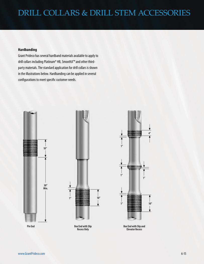
6-15www.GrantPrideco.com
DRILL COLLARS & DRILL STEM ACCESSORIES
Hardbanding
Grant Prideco has several hardband materials available to apply to
drill collars including Platinum® HB, SmoothX™ and other third-
party materials. The standard application for drill collars is shown
in the illustrations below. Hardbanding can be applied in several
configurations to meet specific customer needs.
Box End with Slip Recess Only
Box End with Slip and Elevator Recess
Pin End
10”
30” Min.
10”1”
4”
1”
1”
1”
1”
10”

6-16
DRILL COLLARS & DRILL STEM ACCESSORIES
Care and Maintenance
Initial Make-up
A generous and thorough application of high-quality thread dope
(minimum 40-60% by weight metallic zinc) will help minimize
galling.
New connections should be “walked in” with chain tongs. Always
use the recommended make-up torque for the connection type.
Verify that torque measuring equipment is properly calibrated.
After initial makeup, break out the connection, then clean and
inspect the threads, faces and shoulders. Repair any minor damage,
re-lubricate and re-make the connection.
Repeat breakout and makeup a third time before going into the
hole. Monitor break-out torque; it should be the same or less than
the make-up torque. High break-out torque is an indication of
damage, and the connection should be inspected.
Maintenance
Use thread protectors on both connection ends when handling drill
collars. Rotate connection breaks on each trip. Clean and inspect
the individual connections. Qualified personnel should periodically
conduct a magnetic particle/black light inspection. Collars that are
left idle or put in storage should be cleaned, inspected, repaired
and rust-proofed, as necessary, before installing thread protectors.
Bending Strength Ratios
Sizes less than six inches should have a Bending Strength Ratio
(BSR) of 2.25:1 to 2.75:1. Conditions that require high RPM and
small collars compared to the hole size, use 2.25:1 to 3.00:1. If the
RPM is kept low and the collars are closer to the hole size, use 2.25:1
to 3.20:1. In corrosive environments, use 2.50:1 to 3.00:1.
Although the current industry BSR calculation for single-shoulder
rotary-shouldered connection types may still be applicable for
double-shoulder connections (HT™, XT®, GPDS™), the appropriate
target ranges are yet to be defined due to limited industry
experience and testing of available types/sizes. Testing performed
to date indicates that current target BSR of 2.5 does not apply to
tested double-shouldered connections.
Just as target BSR for single shoulder rotary-shouldered connec-
tions has taken many years of industry experience to define, the
same may be true for these double-shoulder offerings. Additionally,
target BSRs for double-shouldered connections may likely vary
between connection types (i.e. GPDS vs. XT). Current industry
target BSR ranges should not be used as an indicator of double-
shoulder acceptance/rejection.

SERV
ICE & SU
PP
OR
T
SERVICE & SUPPORT

SER
VIC
E &
SU
PP
OR
T
SERVICE & SUPPORT

8-1www.GrantPrideco.com
SERVICE & SUPPORT
In addition to manufacturing quality drill stem products to meet
every drilling situation, including the world’s most challenging
wells, Grant Prideco provides a full complement of service and
support:
Whether technical assistance with a drill stem design, training for a
rig crew or repair threading at one of many licensed repair facilities,
Grant Prideco provides a team of professionals to assist you around

8-2
SERVICE & SUPPORT
Technical Support
Grant Prideco employs fully staffed engineering and metallurgical
specialists will create custom designs according to specific
engineering resources include:
means Grant Prideco offers optimum solutions to your most

8-3www.GrantPrideco.com
SERVICE & SUPPORT
Field Support
Grant Prideco field service representatives provide professional
field service representative offers the following services and
data
licensed repair facilities
engineering and technical staff

SERVICE & SUPPORT
Tool Joint Break-In Service
Grant Prideco’s drill pipe services are designed to deliver consis-
Internal Plastic Coating
stem products from Grant Prideco.
5,000 10,000 15,000 20,000 25,000
Well Depth
Savi
ngs (
$)
2,500,000
2,000,000
1,500,000
1,000,000
500,000
0
Semisub 4,000’ + WD
Drillship 4,000’ + WD
Jackup IC 300’ + WD
Jackup IC < 250’ WD
Inland barge
Spread rates based on 2 times day rate from Rigzone, 4-25-06.

8-5www.GrantPrideco.com
SERVICE & SUPPORT
Licensed Repair and Accessory Network
Grant Prideco’s worldwide manufacturing plants are complemented
support for Grant Prideco products. A full-time audit department
certifies individual facilities and ensures that proper manufacturing
and quality control procedures are followed. Grant Prideco’s
technical support to all manufacturing and repair locations,
8-6
SERVICE & SUPPORT
Training and Seminars
a hands-on approach to learning new rig procedures, and reduce
ensures that crews are always updated in the latest techniques,
on a variety of drill pipe topics, including: