Embed Size (px)
Citation preview
International Journal of Engineering Research & Science (IJOER) ISSN: [2395-6992] [Vol-2, Issue-8, August- 2016]
Page | 84
Reduction of Torque Ripple of Segmental Type Switched
Reluctance Motor Controlled with dsPIC Hakan Terzioğlu
1, Saadetdin Herdem
2, Güngör Bal
3
1Department of Electric and Energy, Vocational School of Technical Sciences Selçuk University, Konya/TURKEY
Email: hterzioglu @selcuk.edu.tr 2Department of Electrical and Electronics Engineering, Engineering Faculty, Selcuk University, Konya/TURKEY
Email:[email protected] 3Department of Electrical and Electronics Engineering, Faculty of Technology Gazi University, Ankara/TURKEY
Email: [email protected]
Abstract—In this study, in order to reduce torque ripple of 5 phase-10/8 segmental type switched reluctance motor (SRM) a
controller was designed and then performed. The SRM was controlled as a bipolar by H-bridge topology with flexible
controller circuit. To determine the effectiveness of the designed driver circuit, the motor was operated at various conditions
and the torque ripple of the motor was recorded. The SRM was driven by the H-bridge converter topology which can operate
at both constant frequency signal and signal obtained from the encoder. The obtained results showed that the torque ripple
of the SRM is reduced by using the encoder signals rather than the constant frequency signal. This control technique
demonstrated that the torque ripple of the SRM can be kept within acceptable limits.
Keywords— dsPIC33, H-Bridge Converter, Segmental Type Switched Reluctance Motor, Torque Ripple.
I. INTRODUCTION
Switched Reluctance Motor (SRM) was first introduced by Davidson in 1838 in Scotland to propel an electric locomotive.
Studies on this issue were not performed for many years because the control of switched reluctance motor (SRM) was
difficult. However, the improvements in the motor and the driver circuit techniques have increased the interest of researchers
again.
Today, easily controllable motors with low production cost and high performance have come into prominence. Due to SRM’s
features such as the simple and durable structure, low cost, low inertia, high speed and efficiency, SRMs are widely used
electrical machines nowadays [1]. Although SRMs have many advantages, they haven’t found many usage areas until quite
recently. The necessity to have rotor position information or a position sensor, torque ripple and acoustic noise are important
reasons [2]. From these disadvantages, one of the most significant is ripple occurring in their torques. In many studies,
researchers proposed solutions methods on the physical structure of the motor, drive circuit and control circuit [2]. In the
performed studies, a new SRM with 5 phase-U shape segmental rotor was designed and it was stated that this newly designed
SRM produces more torque than the classical SRM [3]. Besides, Bal G. et al carried out a study to determine the ratio
between the rotor and stator thread width for a high torque and proper output power [4]. A sudden torque control was
fulfilled by using linear magnetic model. Torque control was done by determining commutation angle. In experimental and
simulation results, it was seen that torque ripple was reduced [5]. Speed regulation was performed using model combination
controller (AFCMAC) configurable fuzzy cerebrals [6]. They used ANN model to determine rotor position of SRM. Three
methods that consisted of traditional ANN, developed ANN and developed and curve fitting were compared with each other
[7]. A new troubleshooting was offered for the drivers of SRM. In normal operating conditions, troubleshooting was
determined by comparing magnitudes of power source current and reference current. As a fault, open and short circuit
mistakes were specified. Asymmetric bridge was used as converter structure [8]. Phase inductances were described as vector
quantity and disintegration of orthogonal was used to determine rotor position [9]. The speed of SRM was checked by using
fuzzy control method [10]. By using torque sharing function method, torque waves were minimized and in this way reference
torque values were turned into reference analytical wave directly by means of analytical method [11]. Direct torque control
was advised for SRM by means of Lyapunov function-based stability and the nonlinear magnetization characteristics of SRM
(because of the complex structure of rotor position, torque and phase current). To minimize torque ripple a method was
suggested in [12]. A new stable technique was developed for the speed control applications of SRMs and in the mathematical
model of SRM that was used in this technique, second order sliding mod control and super twisting algorithm diagram were
used [12]. A system where coil current and rotor position could be measured automatically was created to determine
magnetization characteristics of SRM [13]. Using Adaptive ANN controller, the speed control of SRMs, which was
connected to the system driven by variable speed wind turbine, was performed [14]. A 5 phase-segmental type SRM was
designed to increase the torque of SRM. Also, bipolar application strategy was used to increase the torque even more. For
International Journal of Engineering Research & Science (IJOER) ISSN: [2395-6992] [Vol-2, Issue-8, August- 2016]
Page | 85
this, traditional full bridge converter was used. As a result of bipolar application method, a higher torque output was obtained
[15]. A new power converter circuit was created for SRMs [16]. A new SRM was designed by placing permanent magnet
and auxiliary winding in the stator yoke of SRMs. By means of asymmetrical half bridge, traditional SRM and newly
designed SRM were tested [17]. 50 kW SRM was designed for hybrid electrical vehicles (Toyota Prius 2003). In the study,
new SRM and synchronous motor were compared. It was seen that the efficiency of newly designed SRM was %95 and it
reached the targeted torque at the ratio of % 85 [18]. In the study, 5 phase-10/8 segmental type SRM was designed and it was
seen that the ripple of the motor driven by the H- bridge was %56 [19]. The vibration and the noise of the motor could be
reduced with the changes in the design and control system of the motor, and it was determined that trigger angles affect the
torque ripple of the motor [20]. With the control of 8/6 SRM, a new approach was brought to determine the initial and final
of trigger angles of power switches [21].
In this study, 5 phase-10/8 segmental type SRM was controlled by H-Bridge converter topology with help of a
dsPIC33EP512MU810. SRM and H-Bridge with a flexible working structure were driven as bipolar. By using a dsPIC
control card, SRM was controlled at a definite time determined by signals from both the Hall-Effect sensors and the encoder
passing between phases. While the SRM is running, 5 phase currents, torque and speed are measured and the results are
shown in the designed interface. As a result of the performed experiments, the effects of the trigger methods over motor
torque were also determined.
introduction of the paper should explain the nature of the problem, previous work, purpose, and the contribution of the paper.
The contents of each section may be provided to understand easily about the paper.
II. SEGMENTAL TYPE SWITCHED RELUCTANCE MOTOR
In this study 10/8 segmental type SRM with a different rotor structure from classical SRM was used. The rotor of the used
SRM consists of the packages which made of silicon steel sheet and aluminum blocks. Aluminum block, which is used in the
rotor structure, functions as flux barrier and this feature makes a different motor from classical SRM. The rotor structure of
segmental type SRM is U-shape, so it is also called U-Shaped Segmental Type Motor. The cutaway view of segmental type
SRM is shown in Fig. 1 [19]. Specifications of segmental type SRM are given in Table 1.
FIG. 1 THE VIEW OF 5-PHASE SEGMENTAL TYPE SRM
Equation (1) was used to determine the torque ripple of the SRM.
max min
ripple
avg
T -T%T = .100
T (1)
International Journal of Engineering Research & Science (IJOER) ISSN: [2395-6992] [Vol-2, Issue-8, August- 2016]
Page | 86
TABLE 1
SPECIFICATIONS OF SEGMENTAL TYPE SRM No Characteristics Value
1 Maximum torque in 5 A 2.34 Nm
2 Maximum inductance 13 mH
3 Resistance per phase 0.86 Ω
4 Magnetic field energy at 5 A 0.848 Joule
5 Torque/weight ratio 0.22 Nm/kg
6 Phase number 5
7 Stator/Rotor Configuration 10/8
8 Stator phase angle 0.314 rad
9 Rotor phase angle 0.331 rad
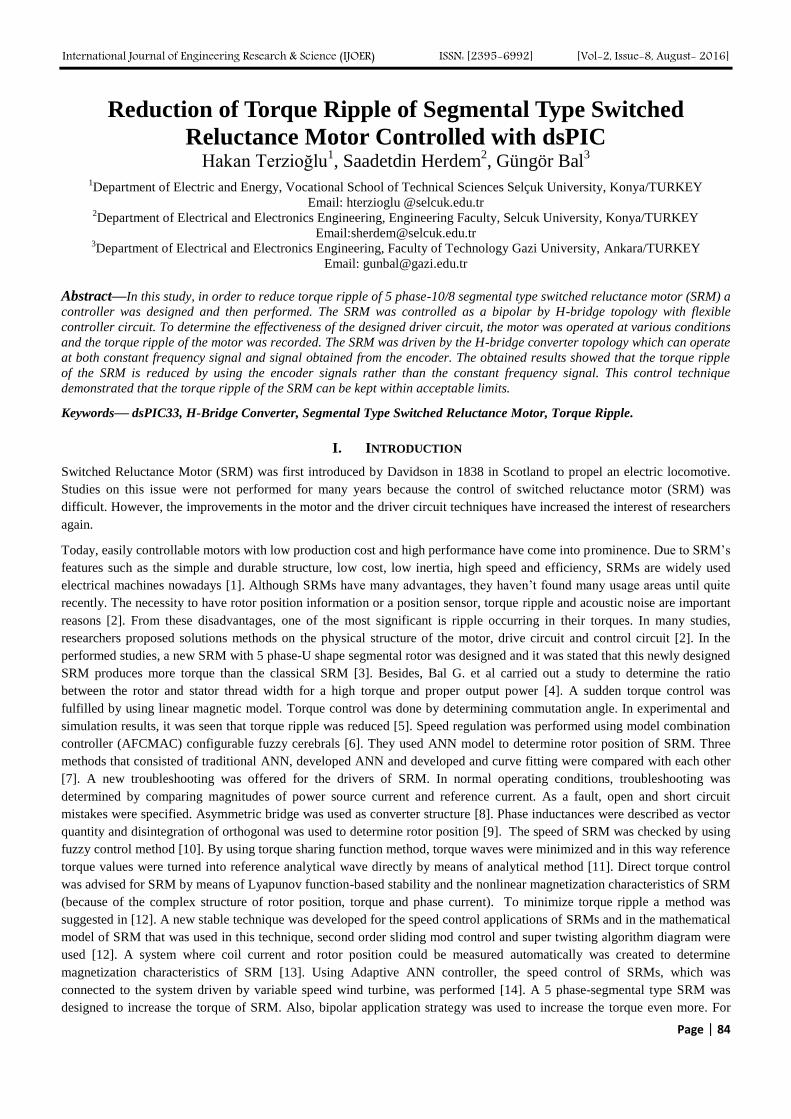
III. H-BRIDGE BIPOLAR CONVERTER TOPOLOGY
The H-Bridge converter topology provides maximum flexibility to observe and produce running modes of the converter [20].
The most important feature of H-Bridge converter topology is that it allows changing the direction of phase. H-bridge driver
is always in modular position and a fault that occurs in one of the phases is automatically isolated from the other phases. This
fault tolerance topology has a feature that can be easily used in automotive applications. The bipolar converter topology uses
more power switches than others.
FIG. 2 H-BRIDGE BIPOLAR CONVERTER TOPOLOGY
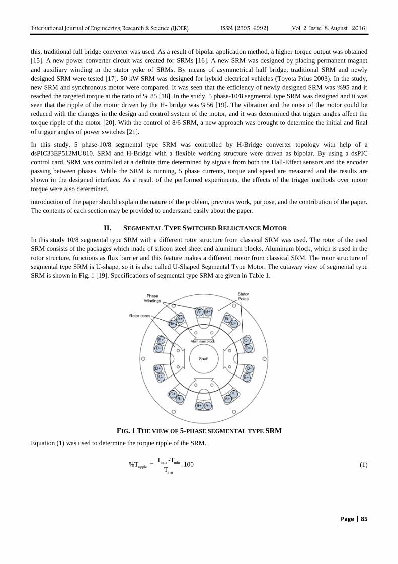
IV. DRIVER CIRCUIT CARD
In order to control the H-bridge converter circuit in SRM driver a dsPIC33EP512MU was used. High performance dsPICs
are preferred because they are highly efficient, more sensitive and long-lasting in sensitive motor control systems. In our
study to control the SRM, a dsPIC was preferred because dsPIC33EP512MU card has 16 bit features, high–speed PWM
feature and it has also USB 2.0 and 10 bit/ 24 channel analogue input. In this study, SnadPIC PIC Microchip development
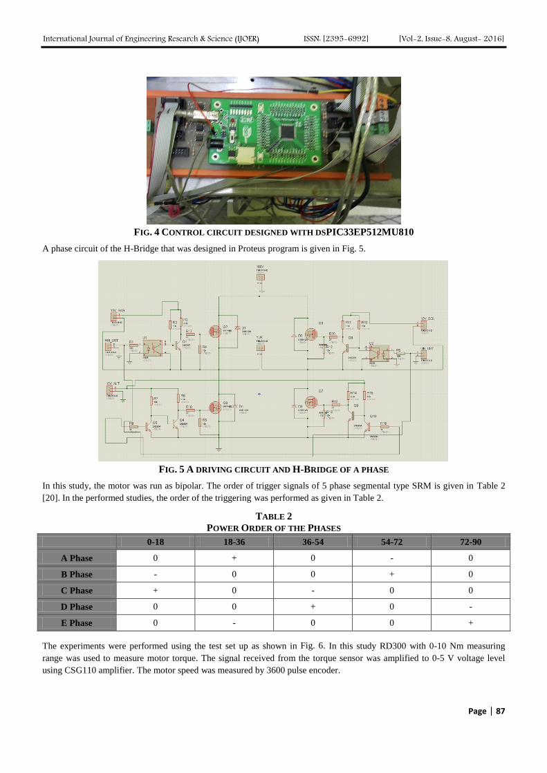
board SD card was used with dsPIC33EP512MU810. A card photo is shown in Fig. 3.
FIG. 3 SNADPIC PIC MICROCHIP DEVELOPMENT BOARD SD CARD
V. EXPERIMENTAL STUDY AND THE RESULTS
In this study, H-Bridge converter structure with the control of dsPIC33EP512MU810 was used for the segmental type SRM.
The picture of dsPIC33EP512MU810 control card is given in Fig. 4.
International Journal of Engineering Research & Science (IJOER) ISSN: [2395-6992] [Vol-2, Issue-8, August- 2016]
Page | 87
FIG. 4 CONTROL CIRCUIT DESIGNED WITH DSPIC33EP512MU810
A phase circuit of the H-Bridge that was designed in Proteus program is given in Fig. 5.
FIG. 5 A DRIVING CIRCUIT AND H-BRIDGE OF A PHASE
In this study, the motor was run as bipolar. The order of trigger signals of 5 phase segmental type SRM is given in Table 2
[20]. In the performed studies, the order of the triggering was performed as given in Table 2.
TABLE 2
POWER ORDER OF THE PHASES
0-18 18-36 36-54 54-72 72-90
A Phase 0 + 0 - 0
B Phase - 0 0 + 0
C Phase + 0 - 0 0
D Phase 0 0 + 0 -
E Phase 0 - 0 0 +
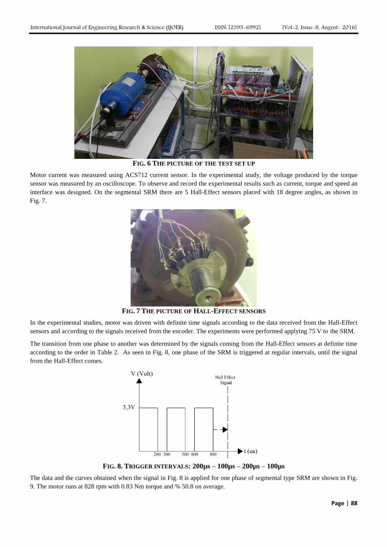
The experiments were performed using the test set up as shown in Fig. 6. In this study RD300 with 0-10 Nm measuring
range was used to measure motor torque. The signal received from the torque sensor was amplified to 0-5 V voltage level
using CSG110 amplifier. The motor speed was measured by 3600 pulse encoder.
International Journal of Engineering Research & Science (IJOER) ISSN: [2395-6992] [Vol-2, Issue-8, August- 2016]
Page | 88
FIG. 6 THE PICTURE OF THE TEST SET UP
Motor current was measured using ACS712 current sensor. In the experimental study, the voltage produced by the torque
sensor was measured by an oscilloscope. To observe and record the experimental results such as current, torque and speed an
interface was designed. On the segmental SRM there are 5 Hall-Effect sensors placed with 18 degree angles, as shown in
Fig. 7.
FIG. 7 THE PICTURE OF HALL-EFFECT SENSORS
In the experimental studies, motor was driven with definite time signals according to the data received from the Hall-Effect
sensors and according to the signals received from the encoder. The experiments were performed applying 75 V to the SRM.
The transition from one phase to another was determined by the signals coming from the Hall-Effect sensors at definite time
according to the order in Table 2. As seen in Fig. 8, one phase of the SRM is triggered at regular intervals, until the signal
from the Hall-Effect comes.
FIG. 8. TRIGGER INTERVALS: 200µs – 100µs – 200µs – 100µs
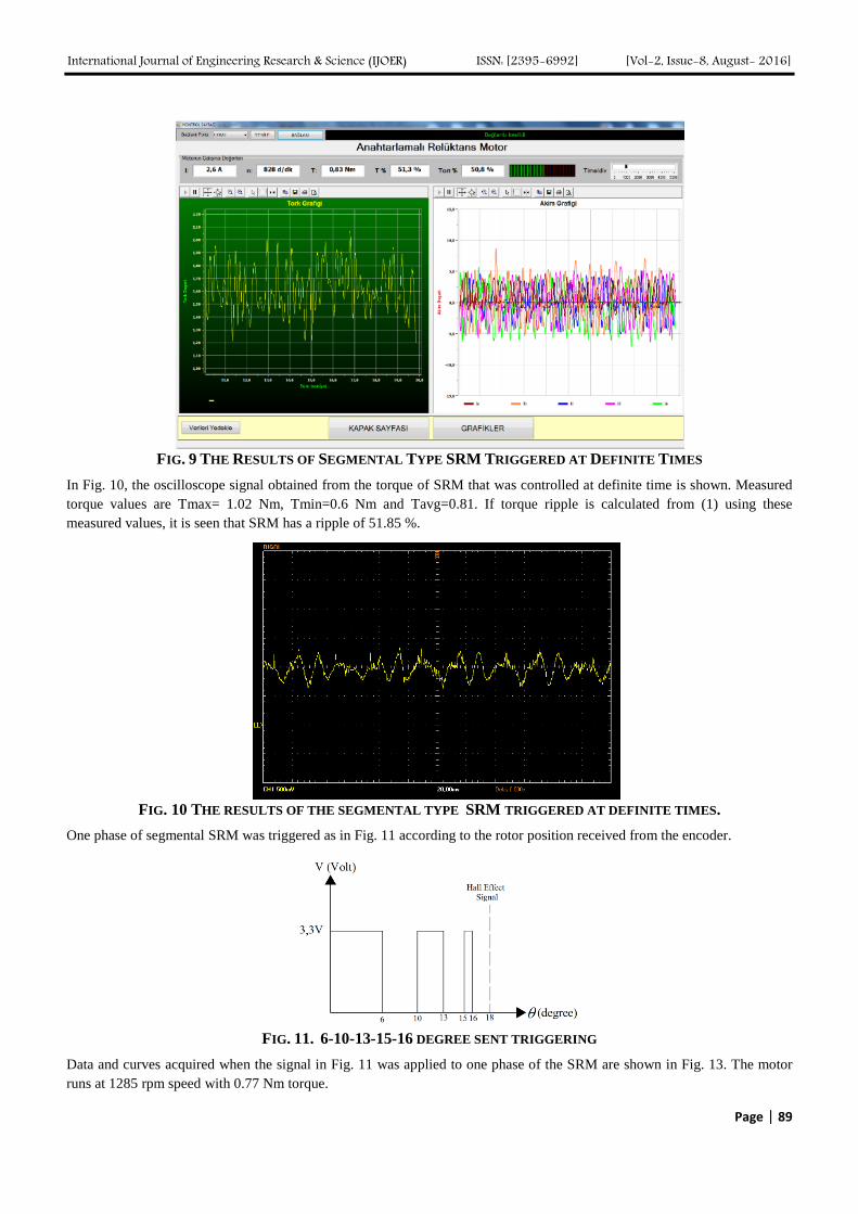
The data and the curves obtained when the signal in Fig. 8 is applied for one phase of segmental type SRM are shown in Fig.
9. The motor runs at 828 rpm with 0.83 Nm torque and % 50.8 on average.
International Journal of Engineering Research & Science (IJOER) ISSN: [2395-6992] [Vol-2, Issue-8, August- 2016]
Page | 89
FIG. 9 THE RESULTS OF SEGMENTAL TYPE SRM TRIGGERED AT DEFINITE TIMES
In Fig. 10, the oscilloscope signal obtained from the torque of SRM that was controlled at definite time is shown. Measured
torque values are Tmax= 1.02 Nm, Tmin=0.6 Nm and Tavg=0.81. If torque ripple is calculated from (1) using these
measured values, it is seen that SRM has a ripple of 51.85 %.
FIG. 10 THE RESULTS OF THE SEGMENTAL TYPE SRM TRIGGERED AT DEFINITE TIMES.
One phase of segmental SRM was triggered as in Fig. 11 according to the rotor position received from the encoder.
FIG. 11. 6-10-13-15-16 DEGREE SENT TRIGGERING
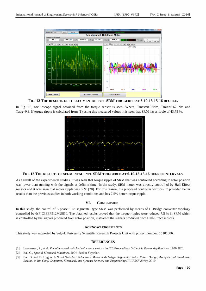
Data and curves acquired when the signal in Fig. 11 was applied to one phase of the SRM are shown in Fig. 13. The motor
runs at 1285 rpm speed with 0.77 Nm torque.
International Journal of Engineering Research & Science (IJOER) ISSN: [2395-6992] [Vol-2, Issue-8, August- 2016]
Page | 90
FIG. 12 THE RESULTS OF THE SEGMENTAL TYPE SRM TRIGGERED AT 6-10-13-15-16 DEGREE.
In Fig. 13, oscilloscope signal obtained from the torque sensor is seen. Where, Tmax=0.97Nm, Tmin=0.62 Nm and
Tavg=0.8. If torque ripple is calculated from (1) using this measured values, it is seen that SRM has a ripple of 43.75 %.
FIG. 13 THE RESULTS OF SEGMENTAL TYPE SRM TRIGGERED AT 6-10-13-15-16 DEGREE INTERVALS.
As a result of the experimental studies, it was seen that torque ripple of SRM that was controlled according to rotor position
was lower than running with the signals at definite time. In the study, SRM motor was directly controlled by Hall-Effect
sensors and it was seen that motor ripple was 56% [20]. For this reason, the proposed controller with dsPIC provided better
results than the previous studies in both working conditions and has 7.5% better torque ripple.
VI. CONCLUSION
In this study, the control of 5 phase 10/8 segmental type SRM was performed by means of H-Bridge converter topology
controlled by dsPIC33EP512MU810. The obtained results proved that the torque ripples were reduced 7.5 % in SRM which
is controlled by the signals produced from rotor position, instead of the signals produced from Hall-Effect sensors.
ACKNOWLEDGEMENTS
This study was supported by Selçuk University Scientific Research Projects Unit with project number: 15101006.
REFERENCES
[1] Lawrenson, P., et al. Variable-speed switched reluctance motors. in IEE Proceedings B-Electric Power Applications. 1980. IET.
[2] Bal, G., Special Electrical Machines. 2004: Seckin Yayınları.
[3] Bal, G. and D. Uygun. A Novel Switched Reluctance Motor with U-type Segmental Rotor Pairs: Design, Analysis and Simulation
Results. in Int. Conf. Computer, Electrical, and Systems Science, and Engineering (ICCESSE 2010). 2010.
International Journal of Engineering Research & Science (IJOER) ISSN: [2395-6992] [Vol-2, Issue-8, August- 2016]
Page | 91
[4] G., B., D. Uygun, An approach to obtain an advisable ratio between stator and rotor tooth widths in switched reluctance motors for
higher torque and smoother output power profile. Gazi University Journal of Science, 2010. 23(4): p. 457-463.
[5] Moron, C., et al., Torque control of switched reluctance motors. IEEE Transactions on Magnetics, 2012. 48(4): p. 1661-1664.
[6] Wang, S.-Y., C.-L. Tseng, and S.-C. Chien, Adaptive fuzzy cerebellar model articulation control for switched reluctance motor drive.
IET electric power applications, 2012. 6(3): p. 190-202.
[7] Zhong, R., Y. Wang, and Y. Xu, Position sensorless control of switched reluctance motors based on improved neural network. IET
Electric Power Applications, 2012. 6(2): p. 111-121.
[8] Gameiro, N.S. and A.J.M. Cardoso, A new method for power converter fault diagnosis in SRM drives. IEEE Transactions on Industry
Applications, 2012. 48(2): p. 653-662.
[9] Cai, J. and Z. Deng, Sensorless control of switched reluctance motor based on phase inductance vectors. IEEE Transactions on
Power Electronics, 2012. 27(7): p. 3410-3423.
[10] Tseng, C.-L., et al., Development of a self-tuning TSK-fuzzy speed control strategy for switched reluctance motor. IEEE Transactions
on Power Electronics, 2012. 27(4): p. 2141-2152.
[11] Vujičić, V.P., Minimization of torque ripple and copper losses in switched reluctance drive. IEEE transactions on power electronics,
2012. 27(1): p. 388-399.
[12] Rafiq, M., et al., A second order sliding mode control design of a switched reluctance motor using super twisting algorithm.
Simulation Modelling Practice and Theory, 2012. 25: p. 106-117.
[13] Wang, S.-C., An fully-automated measurement system for identifying magnetization characteristics of switched reluctance motors.
Measurement, 2012. 45(5): p. 1226-1238.
[14] Hasanien, H.M. and S. Muyeen, Speed control of grid-connected switched reluctance generator driven by variable speed wind
turbine using adaptive neural network controller. Electric Power Systems Research, 2012. 84(1): p. 206-213.
[15] Vandana, R., S. Nikam, and B. Fernandes, High torque polyphase segmented switched reluctance motor with novel excitation
strategy. IET electric power applications, 2012. 6(7): p. 375-384.
[16] Tomczewski, K. and K. Wrobel, Quasi-three-level converter for switched reluctance motor drives reducing current rising and falling
times. IET Power Electronics, 2012. 5(7): p. 1049-1057.
[17] Hasegawa, Y., K. Nakamura, and O. Ichinokura, A novel switched reluctance motor with the auxiliary windings and permanent
magnets. IEEE Transactions on Magnetics, 2012. 48(11): p. 3855-3858.
[18] Takeno, M., et al., Test results and torque improvement of the 50-kW switched reluctance motor designed for hybrid electric vehicles.
IEEE Transactions on Industry Applications, 2012. 48(4): p. 1327-1334.
[19] Uygun, D., Design and Application Of 5-Phase Bipolar Excited 10/8 Switched Reluctance Motor With U-Type Segmental Rotor
Pairs, in Electrical Education. 2012, Gazi University: Graduate School of Natural and Applied Sciences.
[20] M. Polat, E.O.a.H.K., Control of Switched Reluctance Motor and Examination of Effect on the Torque Ripple of the Trigger Points,
in 6th International Advanced Symposium (IATS’11). 2011: Elazıg, Turkey. p. 16-18.
[21] AbouHashesh, S., M. El-Nemr, and E. Rashad. Correlative angles switching technique for switched reluctance motor drive systems.
in GCC Conference and Exhibition (GCCCE), 2015 IEEE 8th. 2015. IEEE.