Embed Size (px)
Citation preview
7/28/2019 Reluctance Flux
http://slidepdf.com/reader/full/reluctance-flux 1/5
FLUX-LINKAGE CHARACTERISTICS OF SWITC ED RELUC''I'ANCEMOTOR
V. Ramanarayanan L.V&tah Debiprasad Pandaw m fEl-Ea-W
Indm Institute of scienoe Indmn Inshtute of Saence
Bangalore 560012 INDIA Eangdore 560012 INDIA Bangalore 560012 INDTA
Dep"ent of ElectricalEngheri@ DepartpentofElectrical EngineeringIndian Instituteof Science
Abstract: An important requirement in modelling ofSwitched reluctance motor (SRM) i s the knowledge of its
flux-linkage characteristics. Idealisation of the flux-linkagecharacteristics will result in a model which cannot predictthe performance of the machine with s afficient accuracy. Itis necessary therefore to determine fludinkagecharacteristicsas closely as &sible.In this paper, the method of finding the flux-linkagecharacteristics is explahed. The same i s demonstrated on acommercially available 4Kw, 8/6 pole OULTONSUM Thevalidity of the test result is cheeked by compnth g the Statictorque characteristics based on the measured flux-linkagech~nteteristiosand compmhg it WMhe experimentally
measured Static torque characteristics. The sources ofmeasurement error are discussed.
JNTRODUCTIONSRMs are drawing considerable attention for variable
speed drive application, owing to its high energy
conversion efficiency. It has sewed advantages over the
COW~X I ~ ~Q I U ~C andDC drives, namely,
.simpleand robust c o me t io n
.brushlessoperation
.low inertia and high torque o weight ratio
.simple power c o m e r tructure
.noshoot through faul tsbetweenDC uses.
The performanceof SRM is innuencedby its flux-linkage
characteristics, and the control strategy. It is to be stressed
that SRM has to be necessarily run from an electronic
power converter. A satisfactory control strategy can be
developed if accurate knowledge of flux-linkagecharacteristicsof the machine is available.
The flux-lhkage in SRM is a function of both rotor
position and the current. The m y f flux-linkage
c b a r i s t i c s (for different rotor positions) will have to be
determined as accurately aspossible. This paper gives, the
method of measurement, sources of experimental error,
andprecaution required in order to reduce the error.
BASIC PRINCIPLEOF OPERATION
Figure 1, shows the construction of an 8/ 6 poles SR motor.
It is doubly salient and has no rotor windings. The torque
in t h i s motor is due to the tendescyof rotor poles to align
wththe poles of the excited stator phase. The direction of
the torque is independent of the direction of the phasecurrent. The phases are cyclically fed by unipolar currents
to get unidirectional torque. A shaft position sensor is
used to facilitate the turn on and turn off of the phasewindings (position sensors can be eliminated with an
indirect position sensing scheme).
Fig1 Cmstrudicmof 816pole SRM
Differentmodes of control are explained in [1-21.
E"LUX-LINKAGE CHARACTERISTICSAN D ITSM E A S ~ M E N T
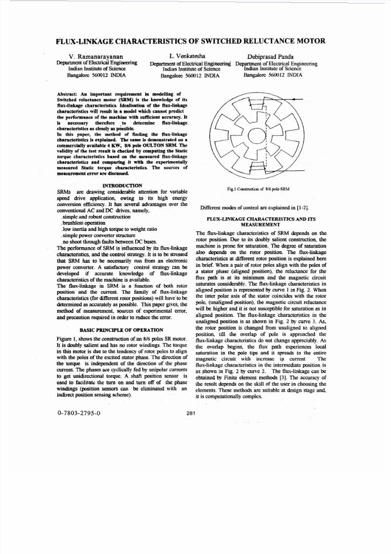
The flux-linkage characteristics of SRM depends on the
rotor position. Due to its doubly salient construction, he
machine is prone for saturation._Thedegree of saturation
ais0 depends on the rotor position. The flux-linkage
characteristics at different rotur position is explained here
in brief. When a pair of rotor poles align with the poles of
a stator phase (aligned position), the reluctance for theflux path is at its minimum and the magnetic circuit
saturates considerably. The flux-linkage characteristics in
aligned position is representedby m e in Fig. 2. When
the inter polar axis of the stator coincides with the rotor
pole, (unaligned psition), the magnetic circuit reluctance
will be higher and it is not susceptible for saturation as in
aiigned position. The flux-linkage 'characteristics in the
unaligned position is as shown in Fig. 2 by c w e 3. As,the rotor position is changed from unaligned to aligned
position, till the overlap of pole is approached the
flux-linkage characteristics do not change appreciably.As
the overlap begins, the flux path experiences local
saturation in the pole tips and it spreads to the entire
magnetic circuit with increase ip current The
flux-linkage characteristics n the intermediate position isas shown in Fig. 2 by curve 2. The flux-linkage can be
obtained by Finite element methods [3]. The accuracy ofthe result depends on the skill of the user in choosing the
elements. These methods are suitable at design stage and,
it is computationally complex
0-7803-2795-0 281
7/28/2019 Reluctance Flux
http://slidepdf.com/reader/full/reluctance-flux 2/5
currenrt
Fig. 2 Flux-linkage&arac te i iAcs ofSRM st cfifferpnl
rotorpitions.
rimntal method ,which makes use of voltage
discussed n detail.When a voltageof thephasesO f S R I q with all other
e quation isgivenby,
(1 )=Ri+d*l&
; R
is the ~~n~~~ voltage acfoss the phase
is its resistance and i the current. The
ted for di€fkrelltvalues of
mtent. One of the s of the motor is
current reach nearly 20 to 30% more than
ament encountered during the
J 11 I
I iJ---Jl I I 1-7 T I
J
0 0005 0 01 0015 002 0025 003 00% 004
io5 t/ov0 00% 001 0015 00 2 0025 003 0035 004
@)
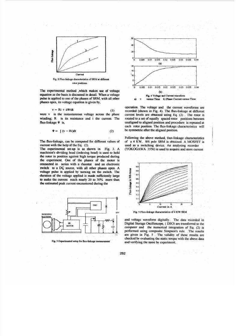
Fig 4 V o b ndCumntwaveform
a) v vasusTime ~ ~ ~ e
operation. The voltage
recorded (shown in Figcurrent feveIs are dbtai
rotated to a set ofequally rotor positionsb e e nunaligned toalignedpositionandprocedure is repeatedateach rotor position.The flux-linkagecharacteristics willbe symmetric after thealignedposition.
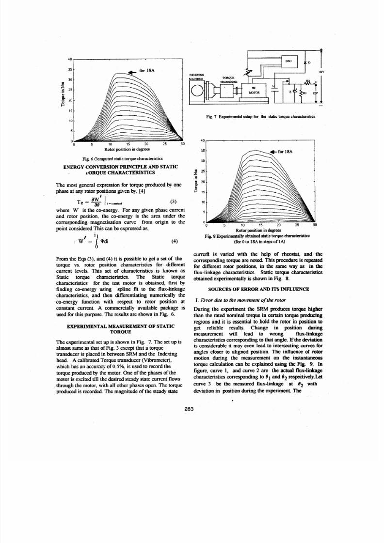
Following the above method,of a 4 KW, 816 pole SRM
used as a switching device.
(YOKOGAWA 3556) is used to acquireand store current
MOSFET i s 1
1, I
09
E oea
$ ;;f ::-
3 0 3
0 2
01
0
-
5 10 15 25
Current inA
computer and then
are given in Fig.
andvenfpng the m echeckedby evaluating
7/28/2019 Reluctance Flux
http://slidepdf.com/reader/full/reluctance-flux 3/5
30
i?.H 20
.G 25
fi15
10
5
0255 10 15 20
Rotor position in degrees
Fig. 6 Com putd static torque characteristics
ENERGY CONVERSIONPRINCIPLEAND STATICiORQUECHARACTERISTICS
The most general expression for torque producedby one
phase at any rotor positions given by, 4]
(3 )
where w' is the coenergy. For any given phase current
and rotor position, the co-energy is the area under the
corresponding magnetisation curve from origin to the
point consideredThis canbe expressed as,
1 i lI W = i q d i
ij(4)
From the Eqs (3). and (4) it is possible to get a set of the
torque vs. rotor position characteristics for Merentcurrent levels. This set of characteristics is known as
Static torque characteristics. The Static torque
characteristics for the test motor is obtained. first by
finding coenergy using spline fit to the flux-linkage
characteristics, and then Werentiating numerically the
coenergy function with respect to rotor position at
constant current. A commercially available package is
used for this purpose.The results are shown in Fig. 6.
EXPERIMENTAL MEA!SUREMENT OF STATICTORQUE
The experimental set up is shown in Fig. 7. Theset up is
almost same as that of Fig. 3 except that a torque
transduceris placed in between SRM and the Indexinghead. A calibrated Torque transducer (Vibrometer),
which has an accuracy of OS% , is used to record the
torque producedby the motor. One ofthe phases of the
motor is excited till the desired steady state current flows
tlirough the motor, with all other phases open. The torque
produced is recorded. The magnitudeof the steady state
Fig. 7 ExpwimenEelsetup for the static torque ch&erktks
350 t."
k m5
10
5
00 5 10 15 20 25 30
Rotor positionindegrees
F ig 8Ekpaimentallyobtained static torque ehcCtaiStics(for 0 to 18A in stepsof 1A)
curre& is varied with the help of rheostat, and the
corresponding torque arenoted This procedure s repeated
for different rotor positions, in the same way as in theflux-linkage characteristics. Static torque characteristics
obtainedexperimentally is shown in Fig. 8.
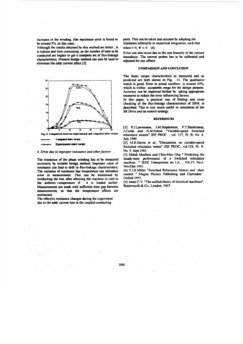
SOURCES OFERROR AND ITS INFLUENCE
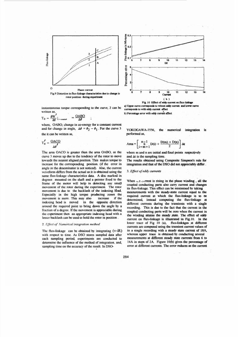
1. Error due to the movernenl of the rotor
During the experiment the SRM produces torque h i ethan the rated nominal torque in certain torque producing
regions and it is essential to hold the rotor in position toget reliable results. Change in position dwilrig
measurement will lead to wrong flux-linkage
characteristics corresponding o that angle. If thedeviation
is considerabie it ma y even lead to intersecting curves for
angles closer to aligned position. The influence of rotormotion during the measurement on the instantaaews
torque Caacdationcanbe eqlained using the Fig. 9. In
figure, m e , and curve 2 are the act4 flux-linkage
characteristics corresponding to 81and 82 respe&vely.Let
c u r v e 3 bethemeasuredfludinkage at 82 with
deviation in position during the experiment.The
.283
7/28/2019 Reluctance Flux
http://slidepdf.com/reader/full/reluctance-flux 4/5
7/28/2019 Reluctance Flux
http://slidepdf.com/reader/full/reluctance-flux 5/5
increases in the winding. (the maximum error is found tobe around 5% ,inthis case).
Although the results obaimxi by th is method are better , tis t d o u s and ime consuming ,as he number of ests tobe
COlKRLctedare higher to get a completeset of flux-linkagecharacteristics.Presscot bridge"dan also be used o
eliminate the eddy current effect [ 5 ] .
1
4. Error due to improper resistance and otherfactors
The resistance o f t he phasewinding has to be measuredaccurately by suitable bridge method. Improper value of
resistance can lead to driA in flux-linkage characteristics.
The variation of resistance due emperature can introduce
error in EN DL This can be minimised by
conducting the test, after allowing the machine to cool to
the ambient *temperature if it is loaded earlier.
Measwwnents are made with sui6cient time gap betweenmeasurements, $0 that the temperature ef fec ts are
minimisedTheeffective resistancechangesduring the experiment
due to the eddy ame nt loss in the coupled conducting
parts. l% s can be aken into account by adapting the
resistance arbiuarily in numerical integration, such that
when i = O , 9 =0 [4].
Error can also occur due o the non linearity in the current
transducer. The current probes has to be calibrated andadjusted or any offsets.
COMPAREON AND CONCLUSION
The Static torque characteristics as measured and as
predicted are both shown in Fig. 11. The qualitative
match is good Error in actual numbers is around loo/,
which is within accqtable range for the design purpose.
Accuracy can be improved further by taking appropriate
measures o reducethe error influencingfactors.
Ln this paper, a practical way of finding and cross
checking of the flux-linkslge characteristics of SRM. s
descri bed,This s very much useful in simulation of the
SR Drive and its control strategy.
REFERENCES
[11 P.J.Lawrenson, J.M.Stephenson, P.T.Blenkiwp,
J.Cor& and N.M.Fulton "Variable-speed Switched
reluctance motors" LEE PROC.,vol. 127. R. . No. ,
July 1980.
[2] M.R.Harris et al, "Discussions on yariable-speed
Switched reluctance motor" IEE PROC., ol.128, Pt.B.No. . Sept.1981.
131 Mehdi Moallem and Chee-Mun Ong " Predicting the
steady-state performance of a Switched reluctance
machine " EEE Transactions on LA. , Vo1.27, N0.6,Nov/Dec 199 1.
141 T.J.E.Miller "Switched keluctance Motors an d theircontrol " Magna Physics Publishing and Clarendon
Word 1993.
[ 5 ] JonesC.V. "The unified theory of electrical machines",
Butterworth&Co., London, 1967.
285