Embed Size (px)
Citation preview
Optimization Driven Design and Additive Manufacturing Applied for ESA Sentinel-1 Antenna Bracket Alejandro Cervantes Herrera [email protected] Warwickshire, June 16th 2015
Copyright © 2015 Altair Engineering, Inc. Proprietary and Confidential. All rights reserved.
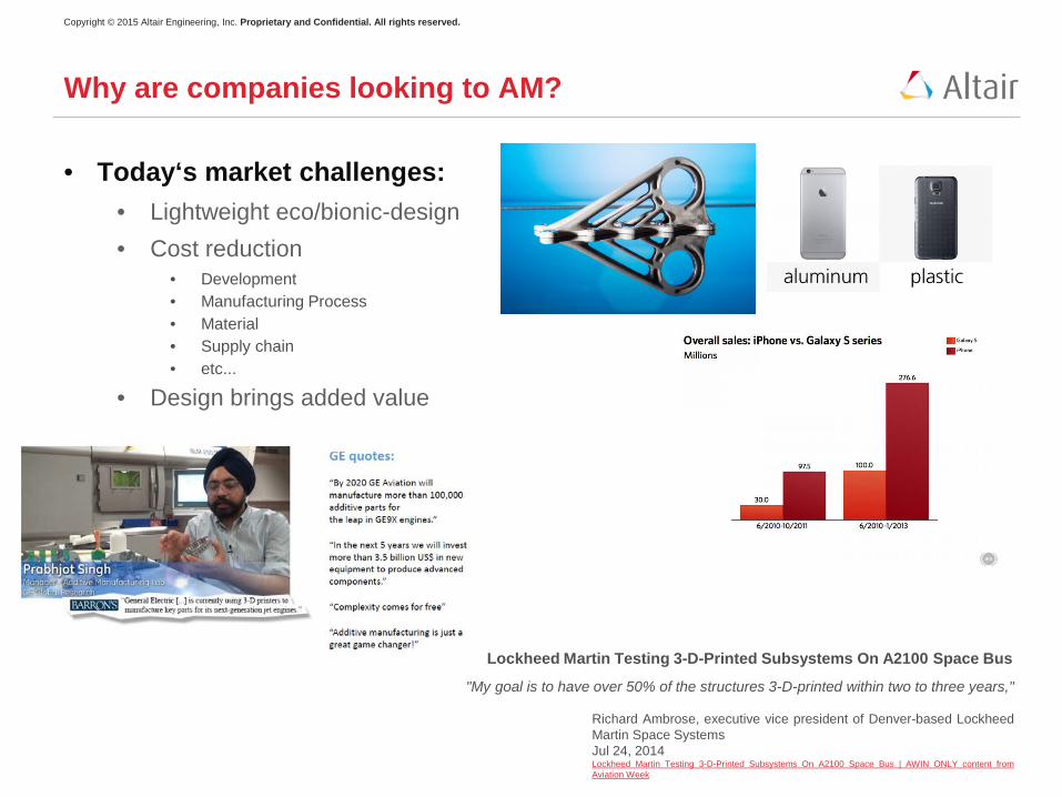
• Today‘s market challenges: • Lightweight eco/bionic-design • Cost reduction
• Development • Manufacturing Process • Material • Supply chain • etc...
• Design brings added value
Why are companies looking to AM?
"My goal is to have over 50% of the structures 3-D-printed within two to three years,"
Richard Ambrose, executive vice president of Denver-based Lockheed Martin Space Systems Jul 24, 2014 Lockheed Martin Testing 3-D-Printed Subsystems On A2100 Space Bus | AWIN ONLY content from Aviation Week
Lockheed Martin Testing 3-D-Printed Subsystems On A2100 Space Bus
Copyright © 2015 Altair Engineering, Inc. Proprietary and Confidential. All rights reserved.
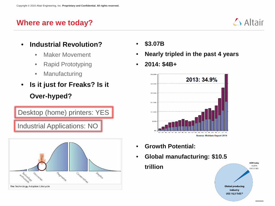
• $3.07B • Nearly tripled in the past 4 years • 2014: $4B+
• Growth Potential: • Global manufacturing: $10.5
trillion
Where are we today?
Desktop (home) printers: YES
Industrial Applications: NO
• Industrial Revolution? • Maker Movement • Rapid Prototyping • Manufacturing
• Is it just for Freaks? Is it Over-hyped?
Copyright © 2015 Altair Engineering, Inc. Proprietary and Confidential. All rights reserved.
How to get on this train?
How to embrace this technology?
Copyright © 2015 Altair Engineering, Inc. Proprietary and Confidential. All rights reserved.
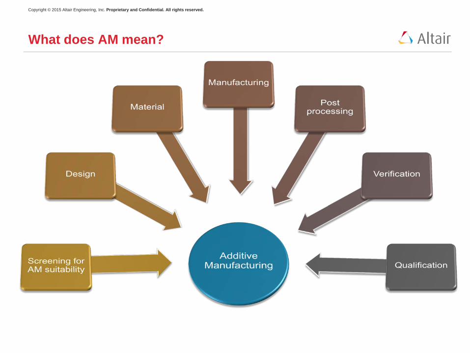
What does AM mean?
Copyright © 2015 Altair Engineering, Inc. Proprietary and Confidential. All rights reserved.
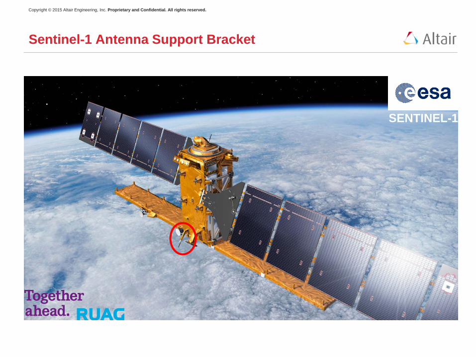
Sentinel-1 Antenna Support Bracket
SENTINEL-1
Copyright © 2015 Altair Engineering, Inc. Proprietary and Confidential. All rights reserved.
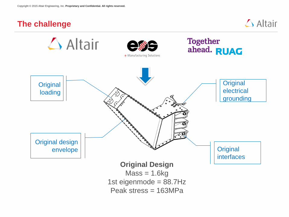
The challenge
Original design envelope Original
interfaces
Original loading
Original electrical grounding
Original Design Mass = 1.6kg
1st eigenmode = 88.7Hz Peak stress = 163MPa
Copyright © 2015 Altair Engineering, Inc. Proprietary and Confidential. All rights reserved.
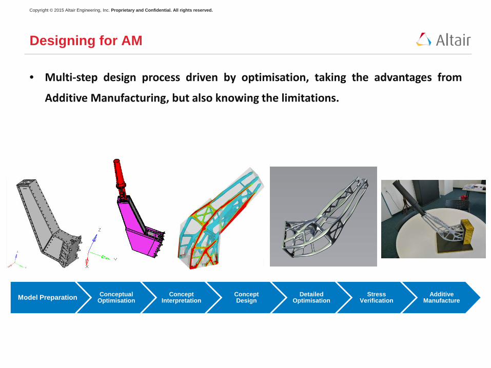
Designing for AM
• Multi-step design process driven by optimisation, taking the advantages from
Additive Manufacturing, but also knowing the limitations.
Model Preparation Conceptual Optimisation
Concept Interpretation
Concept Design
Detailed Optimisation
Stress Verification
Additive Manufacture
Copyright © 2015 Altair Engineering, Inc. Proprietary and Confidential. All rights reserved.
Model Preparation Conceptual Optimisation
Concept Interpretation
Concept Design
Detailed Optimisation
Stress Verification
Additive Manufacture
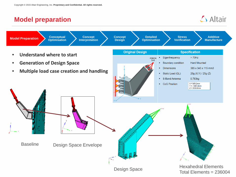
• Understand where to start • Generation of Design Space • Multiple load case creation and handling
Model preparation
Baseline Design Space Envelope
Design Space Hexahedral Elements Total Elements = 236004
Copyright © 2015 Altair Engineering, Inc. Proprietary and Confidential. All rights reserved.
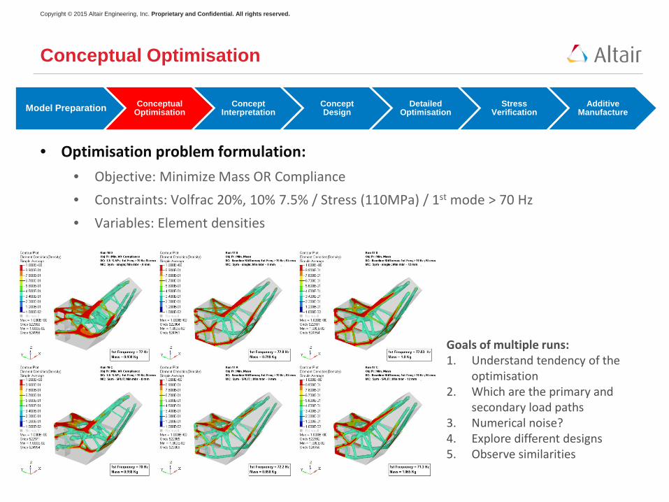
• Optimisation problem formulation: • Objective: Minimize Mass OR Compliance • Constraints: Volfrac 20%, 10% 7.5% / Stress (110MPa) / 1st mode > 70 Hz • Variables: Element densities
Conceptual Optimisation
Model Preparation Conceptual Optimisation
Concept Interpretation
Concept Design
Detailed Optimisation
Stress Verification
Additive Manufacture
Goals of multiple runs: 1. Understand tendency of the
optimisation 2. Which are the primary and
secondary load paths 3. Numerical noise? 4. Explore different designs 5. Observe similarities
Copyright © 2015 Altair Engineering, Inc. Proprietary and Confidential. All rights reserved.
Model Preparation Conceptual Optimisation
Concept Interpretation
Concept Design
Detailed Optimisation
Stress Verification
Additive Manufacture
Conceptual Design
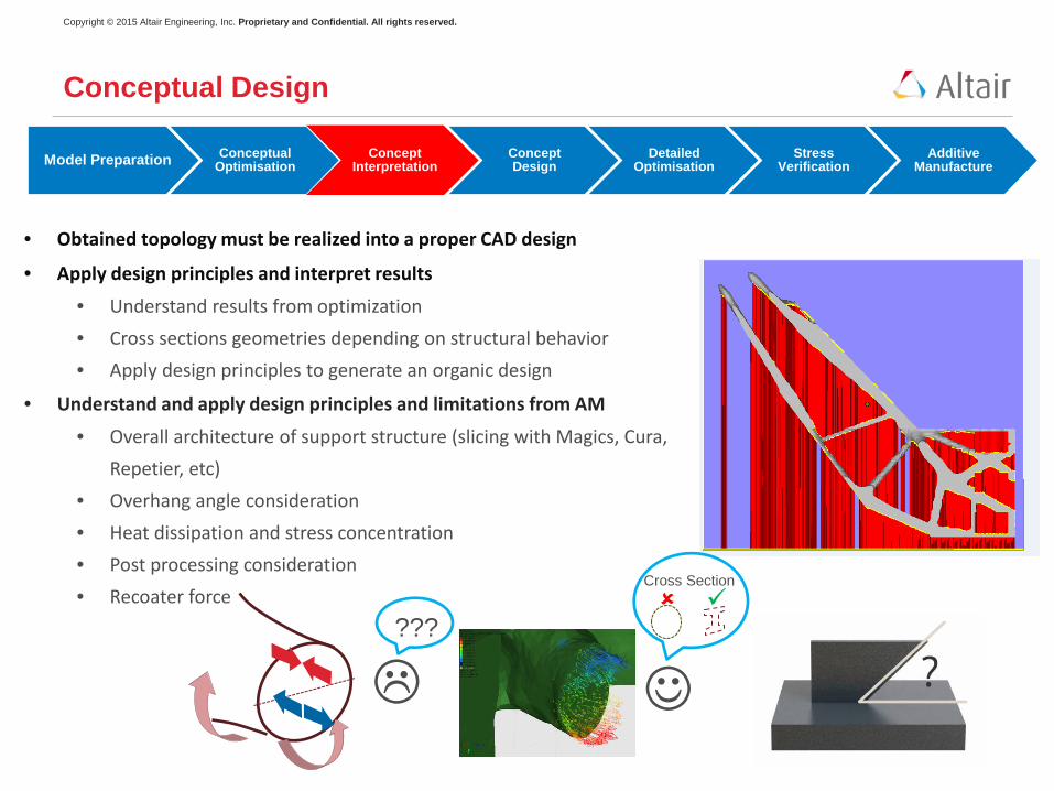
• Obtained topology must be realized into a proper CAD design
• Apply design principles and interpret results
• Understand results from optimization • Cross sections geometries depending on structural behavior • Apply design principles to generate an organic design
• Understand and apply design principles and limitations from AM
• Overall architecture of support structure (slicing with Magics, Cura, Repetier, etc)
• Overhang angle consideration • Heat dissipation and stress concentration • Post processing consideration • Recoater force
???
Cross Section
Copyright © 2015 Altair Engineering, Inc. Proprietary and Confidential. All rights reserved.
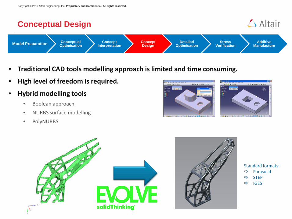
• Traditional CAD tools modelling approach is limited and time consuming.
• High level of freedom is required.
• Hybrid modelling tools • Boolean approach • NURBS surface modelling • PolyNURBS
Model Preparation Conceptual Optimisation
Concept Interpretation
Concept Design
Detailed Optimisation
Stress Verification
Additive Manufacture
Conceptual Design
Standard formats: Parasolid STEP IGES
Copyright © 2015 Altair Engineering, Inc. Proprietary and Confidential. All rights reserved.
Model Preparation Conceptual Optimisation
Concept Interpretation
Concept Design
Detailed Optimisation
Stress Verification
Additive Manufacture
Detailed Optimisation
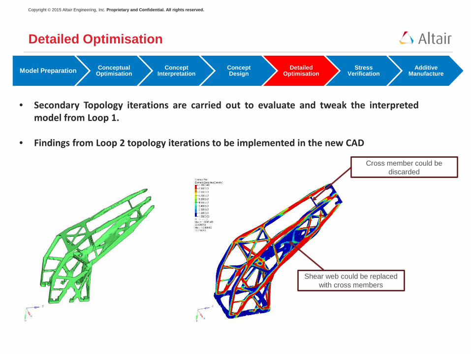
• Secondary Topology iterations are carried out to evaluate and tweak the interpreted model from Loop 1.
• Findings from Loop 2 topology iterations to be implemented in the new CAD
Shear web could be replaced with cross members
Cross member could be discarded
Copyright © 2015 Altair Engineering, Inc. Proprietary and Confidential. All rights reserved.
Model Preparation Conceptual Optimisation
Concept Interpretation
Concept Design
Detailed Optimisation
Stress Verification
Additive Manufacture
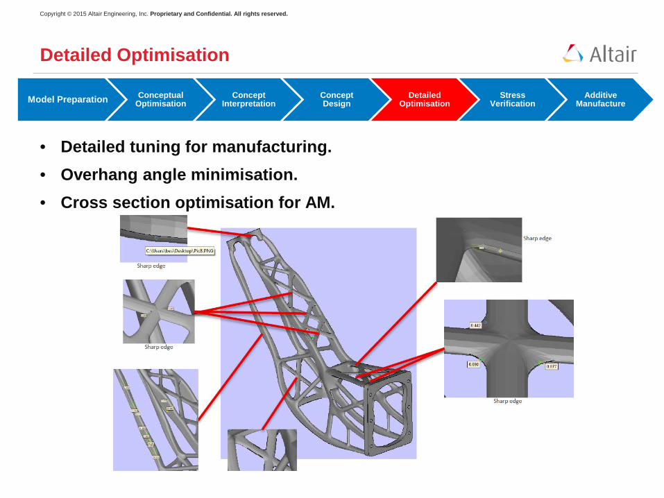
• Detailed tuning for manufacturing. • Overhang angle minimisation. • Cross section optimisation for AM.
Detailed Optimisation
Copyright © 2015 Altair Engineering, Inc. Proprietary and Confidential. All rights reserved.
Model Preparation Conceptual Optimisation
Concept Interpretation
Concept Design
Detailed Optimisation
Stress Verification
Additive Manufacture
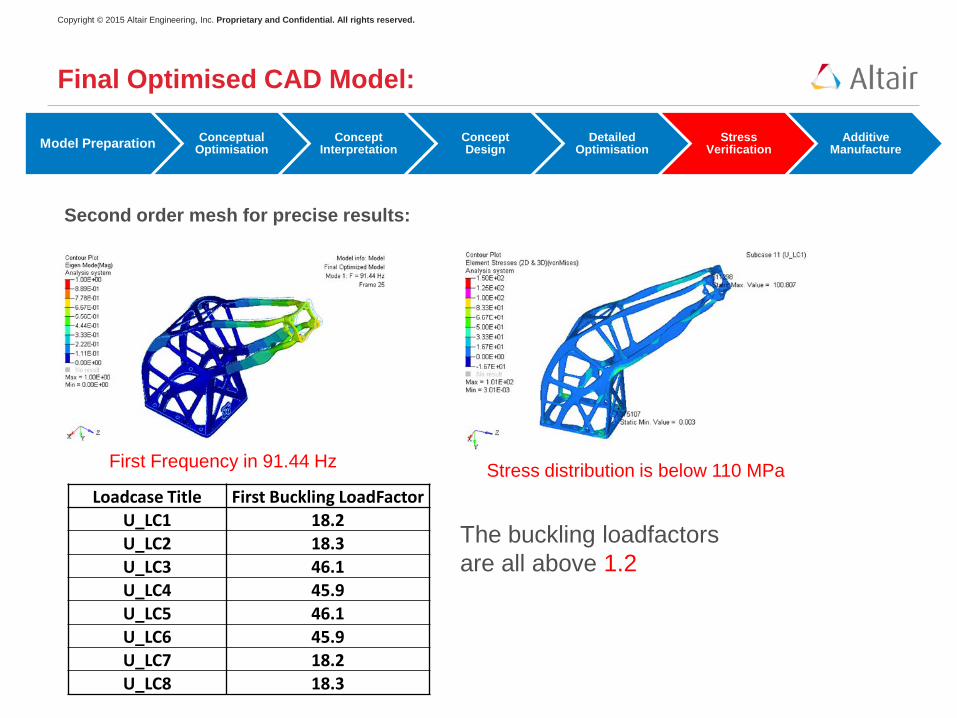
Final Optimised CAD Model:
Loadcase Title First Buckling LoadFactor U_LC1 18.2 U_LC2 18.3 U_LC3 46.1 U_LC4 45.9 U_LC5 46.1 U_LC6 45.9 U_LC7 18.2 U_LC8 18.3
The buckling loadfactors are all above 1.2
Stress distribution is below 110 MPa First Frequency in 91.44 Hz
Second order mesh for precise results:
Copyright © 2015 Altair Engineering, Inc. Proprietary and Confidential. All rights reserved.
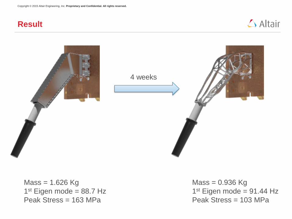
Result
Mass = 1.626 Kg 1st Eigen mode = 88.7 Hz Peak Stress = 163 MPa
Mass = 0.936 Kg 1st Eigen mode = 91.44 Hz Peak Stress = 103 MPa
4 weeks
Copyright © 2012 Altair Engineering, Inc. Proprietary and Confidential. All rights reserved.
Model Preparation Conceptual Optimisation
Concept Interpretation
Concept Design
Detailed Optimisation
Stress Verification
Additive Manufacture
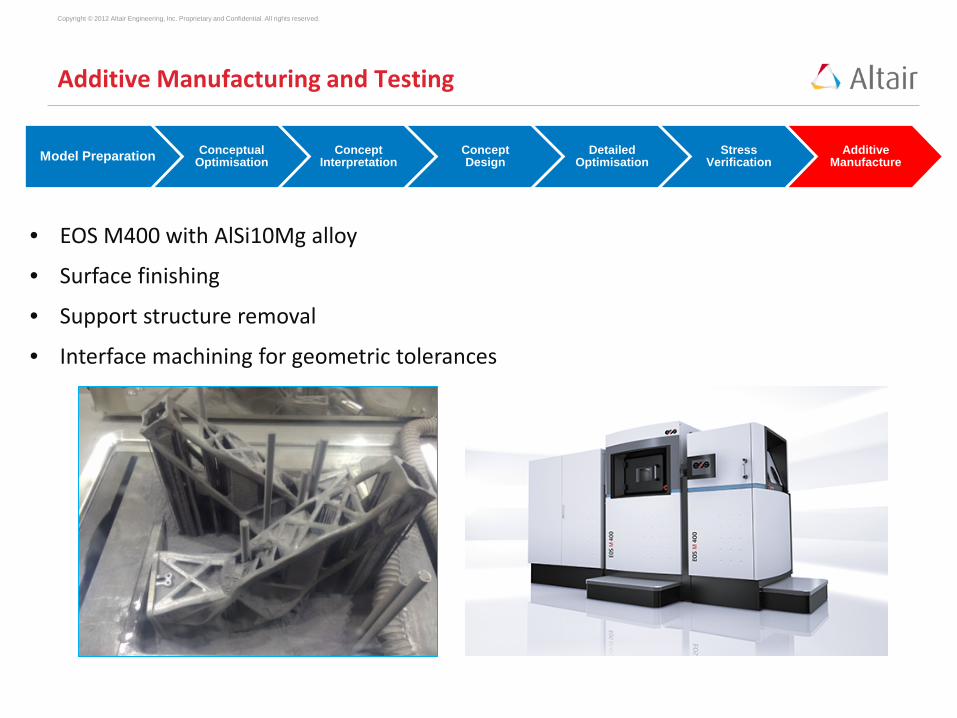
Additive Manufacturing and Testing
• EOS M400 with AlSi10Mg alloy
• Surface finishing
• Support structure removal
• Interface machining for geometric tolerances

Copyright © 2015 Altair Engineering, Inc. Proprietary and Confidential. All rights reserved.
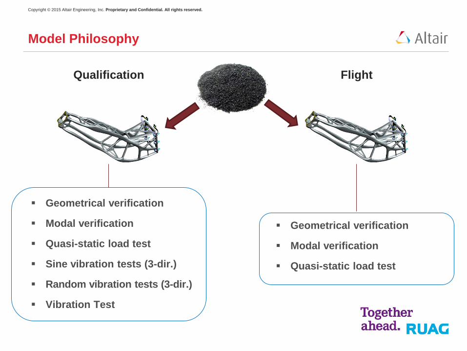
Model Philosophy
Qualification Flight
Geometrical verification
Modal verification
Quasi-static load test
Sine vibration tests (3-dir.)
Random vibration tests (3-dir.)
Vibration Test
Geometrical verification
Modal verification
Quasi-static load test
Copyright © 2015 Altair Engineering, Inc. Proprietary and Confidential. All rights reserved.
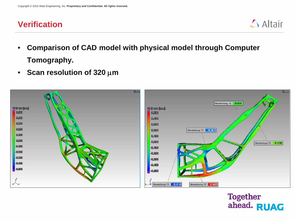
• Comparison of CAD model with physical model through Computer Tomography.
• Scan resolution of 320 µm
Verification
Copyright © 2015 Altair Engineering, Inc. Proprietary and Confidential. All rights reserved.
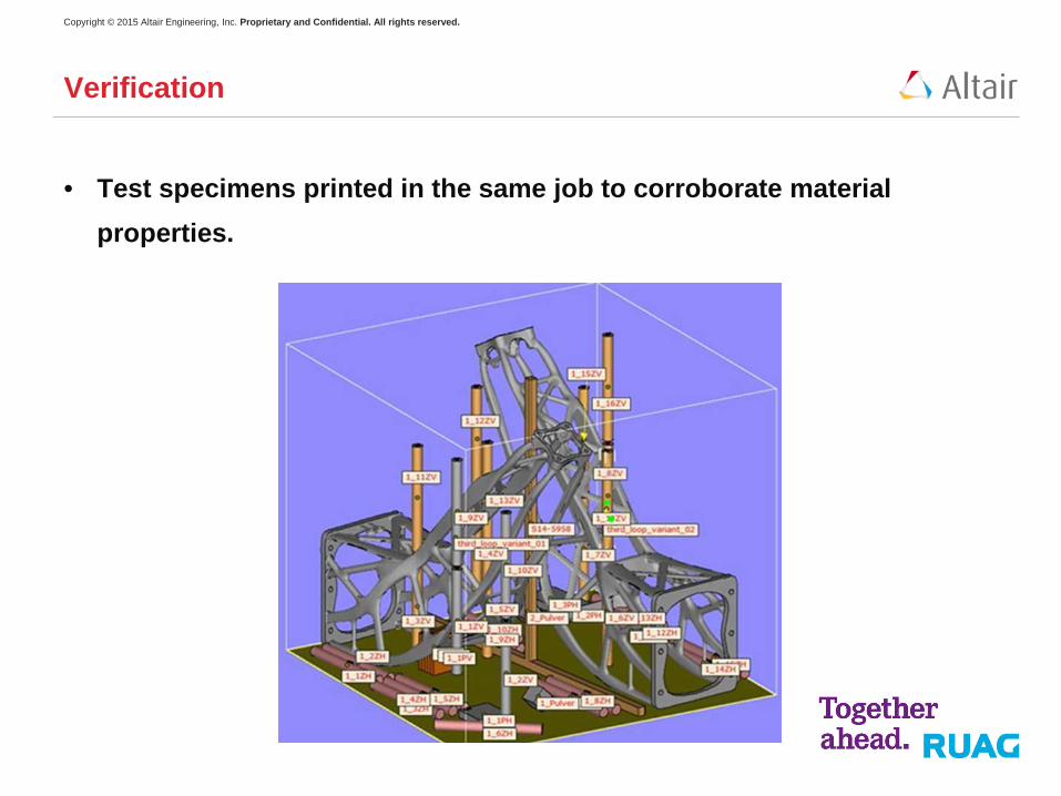
• Test specimens printed in the same job to corroborate material properties.
Verification
Copyright © 2015 Altair Engineering, Inc. Proprietary and Confidential. All rights reserved.
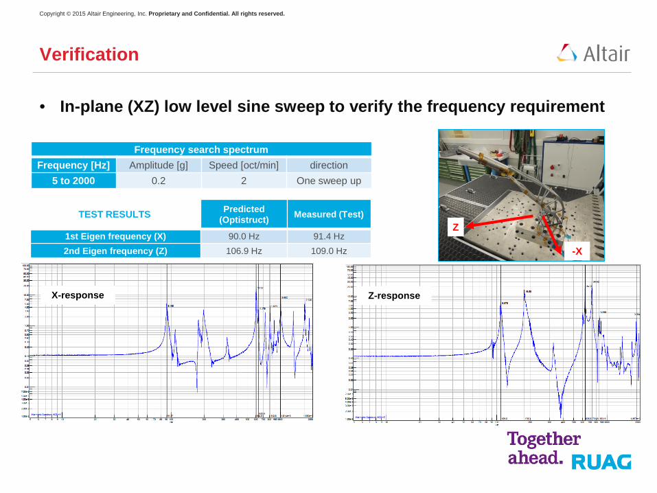
• In-plane (XZ) low level sine sweep to verify the frequency requirement
Verification
Frequency search spectrum Frequency [Hz] Amplitude [g] Speed [oct/min] direction
5 to 2000 0.2 2 One sweep up
TEST RESULTS Predicted (Optistruct) Measured (Test)
1st Eigen frequency (X) 90.0 Hz 91.4 Hz
2nd Eigen frequency (Z) 106.9 Hz 109.0 Hz -X
Z
X-response Z-response
Copyright © 2015 Altair Engineering, Inc. Proprietary and Confidential. All rights reserved.
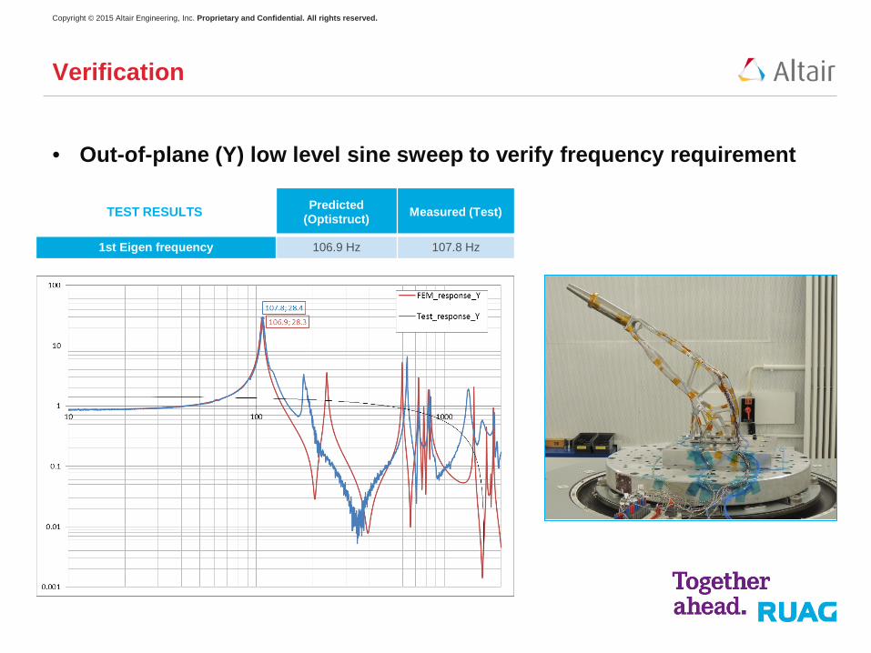
• Out-of-plane (Y) low level sine sweep to verify frequency requirement
Verification
TEST RESULTS Predicted (Optistruct) Measured (Test)
1st Eigen frequency 106.9 Hz 107.8 Hz
Copyright © 2015 Altair Engineering, Inc. Proprietary and Confidential. All rights reserved.
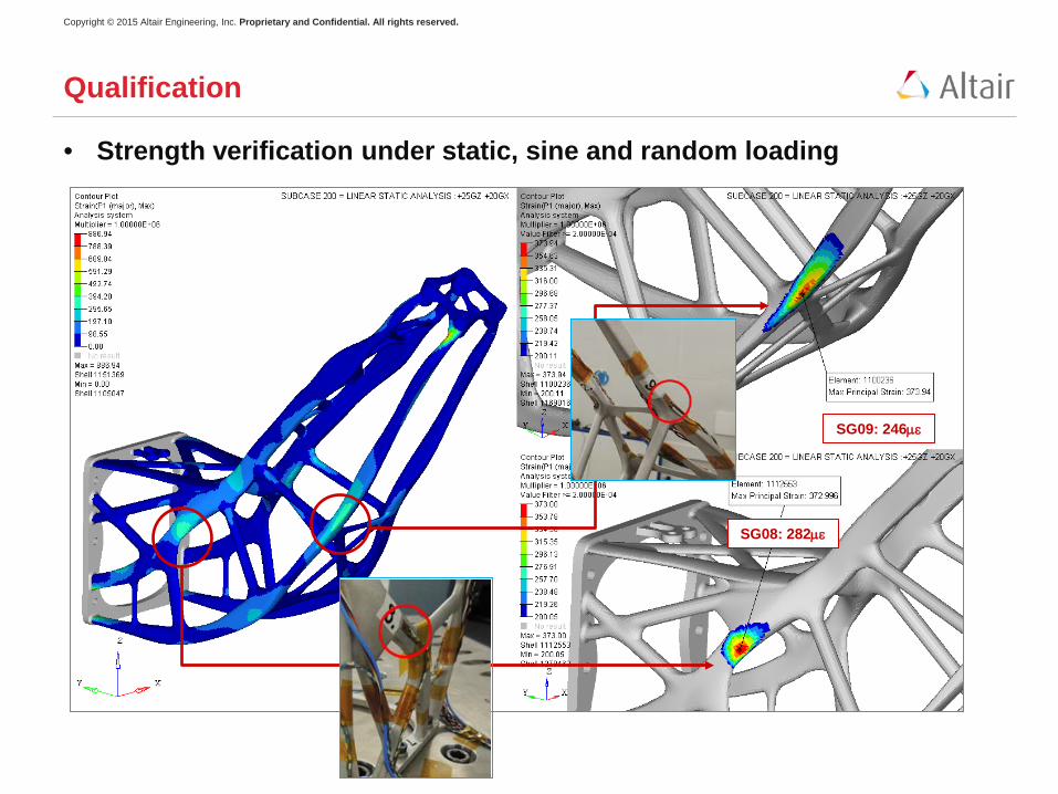
• Strength verification under static, sine and random loading
Qualification
SG08: 282µε
SG09: 246µε
Copyright © 2015 Altair Engineering, Inc. Proprietary and Confidential. All rights reserved.
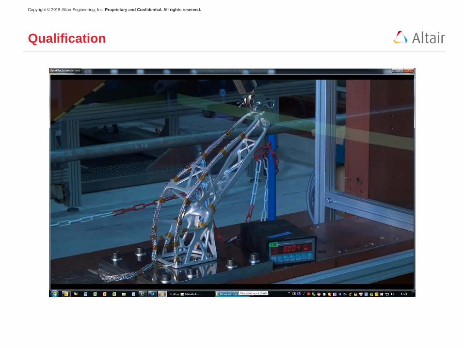
Qualification
Copyright © 2015 Altair Engineering, Inc. Proprietary and Confidential. All rights reserved.
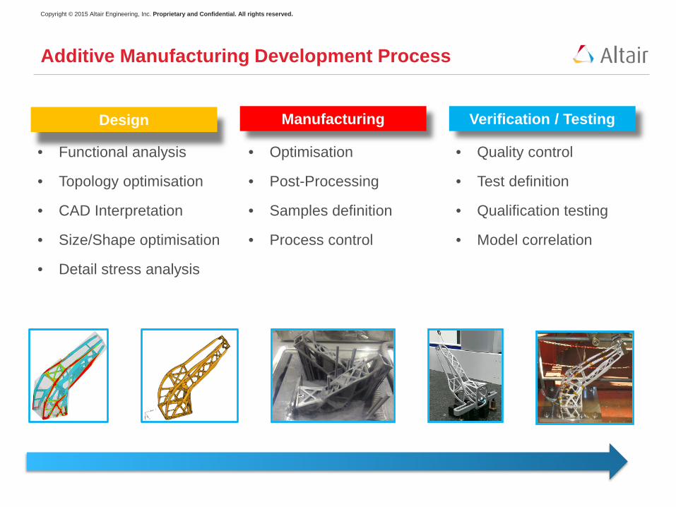
Additive Manufacturing Development Process
Design Manufacturing Verification / Testing
• Functional analysis
• Topology optimisation
• CAD Interpretation
• Size/Shape optimisation
• Detail stress analysis
• Optimisation
• Post-Processing
• Samples definition
• Process control
• Quality control
• Test definition
• Qualification testing
• Model correlation
Copyright © 2015 Altair Engineering, Inc. Proprietary and Confidential. All rights reserved.
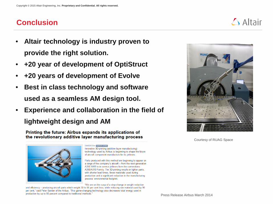
• Altair technology is industry proven to provide the right solution.
• +20 year of development of OptiStruct • +20 years of development of Evolve • Best in class technology and software
used as a seamless AM design tool. • Experience and collaboration in the field of
lightweight design and AM
Conclusion
Press Release Airbus March 2014
Courtesy of RUAG Space
Copyright © 2015 Altair Engineering, Inc. Proprietary and Confidential. All rights reserved.

Copyright © 2015 Altair Engineering, Inc. Proprietary and Confidential. All rights reserved.
Questions
Copyright © 2015 Altair Engineering, Inc. Proprietary and Confidential. All rights reserved.
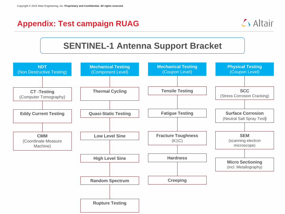
Appendix: Test campaign RUAG
NDT (Non Destructive Testing)
Mechanical Testing (Component Level)
Mechanical Testing (Coupon Level)
Physical Testing (Coupon Level)
CT -Testing (Computer Tomography)
Eddy Current Testing
CMM (Coordinate Measure
Machine)
Thermal Cycling
Quasi-Static Testing
Low Level Sine
Random Spectrum
Rupture Testing
High Level Sine
Tensile Testing
Fatigue Testing
Fracture Toughness (K1C)
Creeping
Hardness
SCC (Stress Corrosion Cracking)
Surface Corrosion (Neutral Salt Spray Test)
SEM (scanning electron
microscope)
Micro Sectioning (incl. Metallography)
SENTINEL-1 Antenna Support Bracket