Varec, Inc.5834 Peachtree Corners East, Norcross (Atlanta), GA 30092 USA
Tel: +1 (770) 447-9202 Fax: +1 (770) 662-8939
www.varec.com
6000 IOM007NVAE1103
6000 Servo Tank GaugeIntelligent tank gauge with high accuracy performance
Installation and Operations Manual

IOM007NVAE1103 2
6000
Servo Tank Gauge
3 Installation and Operations Manual
Table of Contents
General Notes . . . . . . . . . . . . . . . . . . . . . . . . . . . . . . . . . . . . . . . . . . . . . . . . . . . . . . . . . . .6
1 Safety Instructions . . . . . . . . . . . . . . . . . . . . . . . . . . . . . . . . . . . . . . . . . . . . . . . . . . . . .7
2 System Configuration . . . . . . . . . . . . . . . . . . . . . . . . . . . . . . . . . . . . . . . . . . . . . . . . . .9
3 Specifications and Dimensions . . . . . . . . . . . . . . . . . . . . . . . . . . . . . . . . . . . . . . . . .123.1 Typical Specifications . . . . . . . . . . . . . . . . . . . . . . . . . . . . . . . . . . . . . . . . . . . . . . . . . . . . . . . . . . . . . .123.2 Dimensions . . . . . . . . . . . . . . . . . . . . . . . . . . . . . . . . . . . . . . . . . . . . . . . . . . . . . . . . . . . . . . . . . . . . . .14
4 Necessary Tools for Installation . . . . . . . . . . . . . . . . . . . . . . . . . . . . . . . . . . . . . . . . .15
5 Mounting . . . . . . . . . . . . . . . . . . . . . . . . . . . . . . . . . . . . . . . . . . . . . . . . . . . . . . . . . . . .165.1 Application drawings for tanks . . . . . . . . . . . . . . . . . . . . . . . . . . . . . . . . . . . . . . . . . . . . . . . . . . . . . . .165.2 Mounting without Guide System. . . . . . . . . . . . . . . . . . . . . . . . . . . . . . . . . . . . . . . . . . . . . . . . . . . . . .175.3 Mounting with Stilling Well . . . . . . . . . . . . . . . . . . . . . . . . . . . . . . . . . . . . . . . . . . . . . . . . . . . . . . . . . .175.4 Mounting with Guide Wire. . . . . . . . . . . . . . . . . . . . . . . . . . . . . . . . . . . . . . . . . . . . . . . . . . . . . . . . . . .19
6 Mounting Preparations . . . . . . . . . . . . . . . . . . . . . . . . . . . . . . . . . . . . . . . . . . . . . . . .206.1 Flange. . . . . . . . . . . . . . . . . . . . . . . . . . . . . . . . . . . . . . . . . . . . . . . . . . . . . . . . . . . . . . . . . . . . . . . . . .206.2 Electrostatic Charge . . . . . . . . . . . . . . . . . . . . . . . . . . . . . . . . . . . . . . . . . . . . . . . . . . . . . . . . . . . . . . .21
7 Cable Connection . . . . . . . . . . . . . . . . . . . . . . . . . . . . . . . . . . . . . . . . . . . . . . . . . . . . .227.1 Cabling . . . . . . . . . . . . . . . . . . . . . . . . . . . . . . . . . . . . . . . . . . . . . . . . . . . . . . . . . . . . . . . . . . . . . . . . .237.2 Input and output . . . . . . . . . . . . . . . . . . . . . . . . . . . . . . . . . . . . . . . . . . . . . . . . . . . . . . . . . . . . . . . . . .297.3 Cable Gland . . . . . . . . . . . . . . . . . . . . . . . . . . . . . . . . . . . . . . . . . . . . . . . . . . . . . . . . . . . . . . . . . . . . .29
8 Displacer and Measuring Wire . . . . . . . . . . . . . . . . . . . . . . . . . . . . . . . . . . . . . . . . . .308.1 Shape, Diameter, and Material . . . . . . . . . . . . . . . . . . . . . . . . . . . . . . . . . . . . . . . . . . . . . . . . . . . . . . .30
9 Touch Control and Programming Matrix . . . . . . . . . . . . . . . . . . . . . . . . . . . . . . . . . .319.1 Display and Operating Elements . . . . . . . . . . . . . . . . . . . . . . . . . . . . . . . . . . . . . . . . . . . . . . . . . . . . .319.2 Functions of the Operating Elements . . . . . . . . . . . . . . . . . . . . . . . . . . . . . . . . . . . . . . . . . . . . . . . . . .319.3 HOME Position . . . . . . . . . . . . . . . . . . . . . . . . . . . . . . . . . . . . . . . . . . . . . . . . . . . . . . . . . . . . . . . . . . .339.4 Access Code. . . . . . . . . . . . . . . . . . . . . . . . . . . . . . . . . . . . . . . . . . . . . . . . . . . . . . . . . . . . . . . . . . . . .349.5 Description of the Programming Matrix . . . . . . . . . . . . . . . . . . . . . . . . . . . . . . . . . . . . . . . . . . . . . . . .359.6 Programming Matrix . . . . . . . . . . . . . . . . . . . . . . . . . . . . . . . . . . . . . . . . . . . . . . . . . . . . . . . . . . . . . . .359.7 Description of the Programming Matrix . . . . . . . . . . . . . . . . . . . . . . . . . . . . . . . . . . . . . . . . . . . . . . . .44
10 Setting/installation of the wire drum and displacer . . . . . . . . . . . . . . . . . . . . . . . . .6610.1 Installation of the Displacer. . . . . . . . . . . . . . . . . . . . . . . . . . . . . . . . . . . . . . . . . . . . . . . . . . . . . . . . .66
10.2 Wire drum setting . . . . . . . . . . . . . . . . . . . . . . . . . . . . . . . . . . . . . . . . . . . . . . . . . . . . . . . . . . . . . . . .68
11Initial Settings. . . . . . . . . . . . . . . . . . . . . . . . . . . . . . . . . . . . . . . . . . . . . . . . . . . . . . . .6911.1 Setting the System Date and Time . . . . . . . . . . . . . . . . . . . . . . . . . . . . . . . . . . . . . . . . . . . . . . . . . . .6911.2 Initial Settings of Density Measurement . . . . . . . . . . . . . . . . . . . . . . . . . . . . . . . . . . . . . . . . . . . . . . .7011.3 Setting the Tank Height. . . . . . . . . . . . . . . . . . . . . . . . . . . . . . . . . . . . . . . . . . . . . . . . . . . . . . . . . . . .70
12 Initial Weight Calibration. . . . . . . . . . . . . . . . . . . . . . . . . . . . . . . . . . . . . . . . . . . . . . .7112.1 Displacer Weight Calibration . . . . . . . . . . . . . . . . . . . . . . . . . . . . . . . . . . . . . . . . . . . . . . . . . . . . . . .7112.2 Weight Table . . . . . . . . . . . . . . . . . . . . . . . . . . . . . . . . . . . . . . . . . . . . . . . . . . . . . . . . . . . . . . . . . . . .72
13Operation of the Displacer. . . . . . . . . . . . . . . . . . . . . . . . . . . . . . . . . . . . . . . . . . . . . .73
14 Level Measurement . . . . . . . . . . . . . . . . . . . . . . . . . . . . . . . . . . . . . . . . . . . . . . . . . . .74
Servo Tank Gauge
4 Installation and Operations Manual
15 On-site Level Calibration . . . . . . . . . . . . . . . . . . . . . . . . . . . . . . . . . . . . . . . . . . . . . .7515.1 Before On-Site Level Calibration. . . . . . . . . . . . . . . . . . . . . . . . . . . . . . . . . . . . . . . . . . . . . . . . . . . . 7515.2 On-Site Level Calibration Procedure. . . . . . . . . . . . . . . . . . . . . . . . . . . . . . . . . . . . . . . . . . . . . . . . . 76
16 Density Measurement . . . . . . . . . . . . . . . . . . . . . . . . . . . . . . . . . . . . . . . . . . . . . . . . .7716.1 Preliminary settings. . . . . . . . . . . . . . . . . . . . . . . . . . . . . . . . . . . . . . . . . . . . . . . . . . . . . . . . . . . . . . 7716.2 Density Measurement . . . . . . . . . . . . . . . . . . . . . . . . . . . . . . . . . . . . . . . . . . . . . . . . . . . . . . . . . . . . 78
17 Interface Measurement . . . . . . . . . . . . . . . . . . . . . . . . . . . . . . . . . . . . . . . . . . . . . . . .7917.1 Upper Interface Measurement . . . . . . . . . . . . . . . . . . . . . . . . . . . . . . . . . . . . . . . . . . . . . . . . . . . . . 7917.2 Lower Interface Measurement . . . . . . . . . . . . . . . . . . . . . . . . . . . . . . . . . . . . . . . . . . . . . . . . . . . . . 79
18 Remote Communication . . . . . . . . . . . . . . . . . . . . . . . . . . . . . . . . . . . . . . . . . . . . . . .8018.1 Serial Pulse Output (V1/022 protocol). . . . . . . . . . . . . . . . . . . . . . . . . . . . . . . . . . . . . . . . . . . . . . . . 8118.2 Rackbus RS 485 . . . . . . . . . . . . . . . . . . . . . . . . . . . . . . . . . . . . . . . . . . . . . . . . . . . . . . . . . . . . . . . . 81
19 Setting for Alarm Outputs (4 contacts) . . . . . . . . . . . . . . . . . . . . . . . . . . . . . . . . . . .8219.1 Alarm Setting. . . . . . . . . . . . . . . . . . . . . . . . . . . . . . . . . . . . . . . . . . . . . . . . . . . . . . . . . . . . . . . . . . . 8219.2 Setting Level and Temperature Alarms. . . . . . . . . . . . . . . . . . . . . . . . . . . . . . . . . . . . . . . . . . . . . . . 8319.3 Alarm History Display . . . . . . . . . . . . . . . . . . . . . . . . . . . . . . . . . . . . . . . . . . . . . . . . . . . . . . . . . . . . 8419.4 List of Alarm Messages. . . . . . . . . . . . . . . . . . . . . . . . . . . . . . . . . . . . . . . . . . . . . . . . . . . . . . . . . . . 84
20 Setting for Analogue 4...20 mA Outputs (2 channels) . . . . . . . . . . . . . . . . . . . . . . . . . . . . . . . . . . . . . . . . . . . . . . . . . . . . . . . . . . . . . . . . . . . . . . . 8520.1 Setting for Output Type . . . . . . . . . . . . . . . . . . . . . . . . . . . . . . . . . . . . . . . . . . . . . . . . . . . . . . . . . . . 8520.2 Settings for Current Output When Error Occurs . . . . . . . . . . . . . . . . . . . . . . . . . . . . . . . . . . . . . . . . . . . . . . . . . . . . . . . . . . . . . . . . . . 86
21 Settings for Operation Inputs . . . . . . . . . . . . . . . . . . . . . . . . . . . . . . . . . . . . . . . . . . .87
22 Settings for 453x Temperature product Connections . . . . . . . . . . . . . . . . . . . . . . . . . . . . . . . . . . . . . . . . . . . . . . . . . . . . . . . . . . . . . . . . . . . . . . . 88
23 Settings for Servo Monitor 4560 Connections . . . . . . . . . . . . . . . . . . . . . . . . . . . . .89
24 Diagnosis and Troubleshooting . . . . . . . . . . . . . . . . . . . . . . . . . . . . . . . . . . . . . . . . .9024.1 Selection of Diagnostic Code and History. . . . . . . . . . . . . . . . . . . . . . . . . . . . . . . . . . . . . . . . . . . . . 9024.2 Error and Status Messages. . . . . . . . . . . . . . . . . . . . . . . . . . . . . . . . . . . . . . . . . . . . . . . . . . . . . . . . 91
Appendix A: Settings after Resetting . . . . . . . . . . . . . . . . . . . . . . . . . . . . . . . . . . . . . . .93
Appendix B: Intelligent Function . . . . . . . . . . . . . . . . . . . . . . . . . . . . . . . . . . . . . . . . . .95
Appendix C: Calculation of Levels and Densities . . . . . . . . . . . . . . . . . . . . . . . . . . . . . . . . . . . . . . . . . . . . . . . . . . . . . . . . . . . . . . . . . . . . . . . . . . 96
Appendix D: Sealing of the Servo Tank Gauge . . . . . . . . . . . . . . . . . . . . . . . . . . . . . . .98
Appendix E: Technical Criteria of the Gas Vapor Explosion-Proof Structure. . . . . . .99
Appendix F: Protection Class (IEC529) . . . . . . . . . . . . . . . . . . . . . . . . . . . . . . . . . . . .101
Appendix G: Operation Commands and New Operation Status . . . . . . . . . . . . . . . .102
Appendix H: Whessoe Matic 550 (WM550) Communication Board Setting . . . . . . .103
Appendix I: Mark / Space (M/S) Communication Board setting . . . . . . . . . . . . . . . . .104
IOM007NVAE1103 5
6000
Appendix J: ENRAF Bi Phase Mark Communication Board Setting . . . . . . . . . . . . . . . . . . . . . . . . . . . . . . . . . . . . . . . . . . . . . . . . . . . . . . . . . 105
Glossary . . . . . . . . . . . . . . . . . . . . . . . . . . . . . . . . . . . . . . . . . . . . . . . . . . . . . . . . . . . . . 106
Servo Tank Gauge
6 Installation and Operations Manual
General Notes Instruction Manual:
• This instruction manual applies to the 6000 Servo Tank Gauge (STG) with V.4.24 or later software installed.
• Please read this manual carefully and make sure you understand its contents before using the product.
• This manual is solely intended to describe product functions and should not be used for any other purpose.
• No part of this manual may be reproduced or reprinted without permission.
• This manual may be subject to change without prior notice.
• This manual was prepared with the highest degree of care. However, should you find any errors or have any questions, contact one of our service offices or your local sales agent.
On safety and improper use:
Follow the safety guidelines presented in this manual when using this product. This is important for ensuring the safe operation of the system to be controlled by the product. If the user does not follow these instructions properly, we cannot guarantee the safety of the system.
Safety Notes
To maintain a high level of safety and to ensure correct operation, the operator should at all time observe the safety notes given in this operating manual. They are indicated by the following pictograms:
Observe this note to prevent serious personal or material damage.
Observe this note to prevent serious material damage.
Observe this note to achieve the specified performance of the instrument.
Product Requirements
• Power sourceCheck the voltage of the power supply before connecting it to the product. It should be the exact voltage required for proper operation of the product.
• Use in hazardous areasWhen using the product in the first or second-class hazard location (Zone 1 or Zone 2) be sure to use an intrinsically safe or pressure and explosion-proof apparatus. Take the utmost care during the installation, wiring, and piping of such apparatus to ensure the safety of the system. For safety reasons, maintenance or repairs on the product while it is being used with such apparatus should only be performed by qualified per-sonnel.
• External connectionWhen an external connection is required, the product should be protectively grounded before it is connected to a measurement object or an external control circuit.
IOM007NVAE1103 7
6000
1. Safety InstructionsWarning! Observe the following notes to prevent serious physical or material damage.
Power supply • Check that voltage and frequency of the local power supply are in the range of the technical data of the instrument before turning on the power. Please refer to Sect.7.
Power supply cable • Use the power supply cable attached to the instrument when it is ordered from the manufacturer, or the cable specified in the instruction.
• The power source should have a ground terminal, and the power supply cable should have a ground line. Please refer to Sect.7.
Grounding • Do not remove the grounding of the instrument when the power supply is turned on. This may set the instrument in a dangerous condition. Please refer to Sect.7.
Wiring • Make sure the grounding of the instrument before connecting input and output to another system.
Use of the instrument The 6000 STG series is designed for level measurement of a liquid in a storage tank or similar facilities.
• It is possible to connect auxiliary instruments in the specification described in this manual. However, the performance of the connected instruments is not guaranteed. Please refer to the instructions attached to the individual instruments when they are connected.
• A hazardous situation may occur if the instrument is used for a purpose that is not designed for or any other improper ways. The instrument has the IEC class 1 (ground terminal).
Use in explosion hazardous areas
• Please use the explosion-proof type for measurement in explosion-hazardous areas.
• Instruments used in explosion hazardous areas should be mounted and wired accord-ing to the explosion-proof regulations.
• Instruments mounted in explosion hazardous areas must not be opened when the Tighten the cable gland firmly.
• The maintenance and repair of the instrument are limited to fulfill the explosionproof regulations.
Servo Tank Gauge
8 Installation and Operations Manual
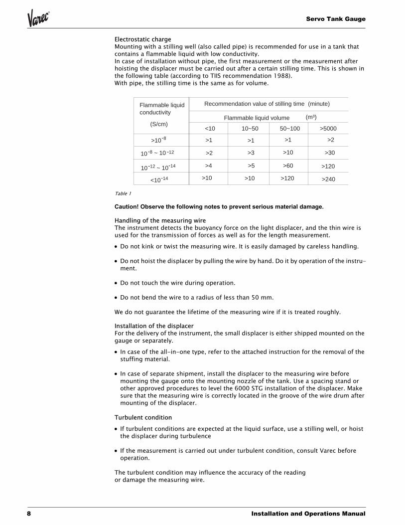
Electrostatic chargeMounting with a stilling well (also called pipe) is recommended for use in a tank that contains a flammable liquid with low conductivity.In case of installation without pipe, the first measurement or the measurement after hoisting the displacer must be carried out after a certain stilling time. This is shown in the following table (according to TIIS recommendation 1988).With pipe, the stilling time is the same as for volume.
Table 1
Caution! Observe the following notes to prevent serious material damage.
Handling of the measuring wireThe instrument detects the buoyancy force on the light displacer, and the thin wire is used for the transmission of forces as well as for the length measurement.
• Do not kink or twist the measuring wire. It is easily damaged by careless handling.
• Do not hoist the displacer by pulling the wire by hand. Do it by operation of the instru-ment.
• Do not touch the wire during operation.
• Do not bend the wire to a radius of less than 50 mm.
We do not guarantee the lifetime of the measuring wire if it is treated roughly.
Installation of the displacerFor the delivery of the instrument, the small displacer is either shipped mounted on the gauge or separately.
• In case of the all-in-one type, refer to the attached instruction for the removal of the stuffing material.
• In case of separate shipment, install the displacer to the measuring wire before mounting the gauge onto the mounting nozzle of the tank. Use a spacing stand or other approved procedures to level the 6000 STG installation of the displacer. Make sure that the measuring wire is correctly located in the groove of the wire drum after mounting of the displacer.
Turbulent condition
• If turbulent conditions are expected at the liquid surface, use a stilling well, or hoist the displacer during turbulence
• If the measurement is carried out under turbulent condition, consult Varec before operation.
The turbulent condition may influence the accuracy of the reading or damage the measuring wire.
Flammable liquidconductivity
Recommendation value of stilling time
Flammable liquid volume(S/cm)
(minute)
(m³)
<10 10~50 50~100 >5000
>10
-810 ~ 10 -12
-12 10 ~ 10-14
<10
-8
-14
>1 >1 >1 >2
>2 >3 >10 >30
>4
>10 >10 >120
>120>60>5
>240
IOM007NVAE1103 9
6000
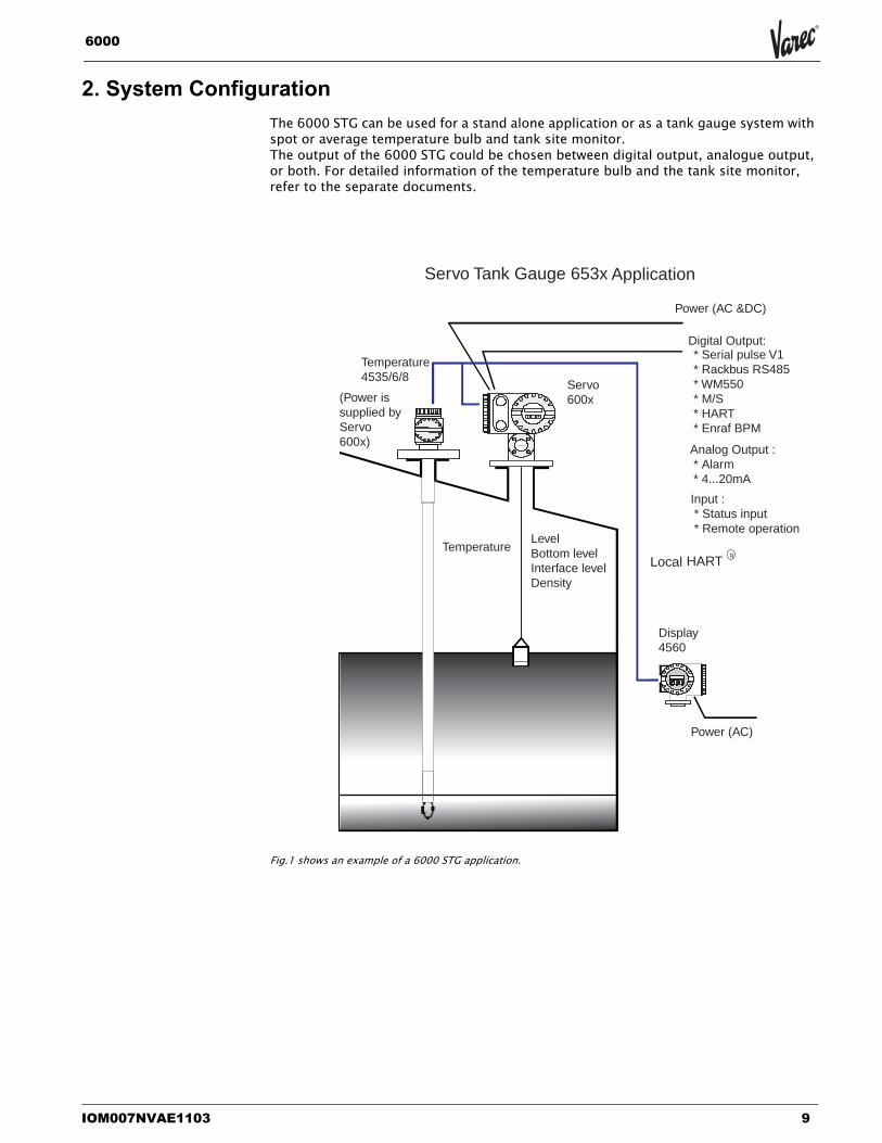
2. System ConfigurationThe 6000 STG can be used for a stand alone application or as a tank gauge system with spot or average temperature bulb and tank site monitor.The output of the 6000 STG could be chosen between digital output, analogue output, or both. For detailed information of the temperature bulb and the tank site monitor, refer to the separate documents.
Fig.1 shows an example of a 6000 STG application.
Local
Temperature4535/6/8
Servo600x
Power (AC &DC)
Power (AC)
TemperatureLevelBottom levelInterface levelDensity
Display4560
HART
Servo Tank Gauge 653x Application
(Power issupplied byServo600x)
Analog Output : * Alarm * 4...20mA
Digital Output:* Serial pulse V1* Rackbus RS485* WM550* M/S* HART* Enraf BPM
R
Input : * Status input * Remote operation
Servo Tank Gauge
10 Installation and Operations Manual
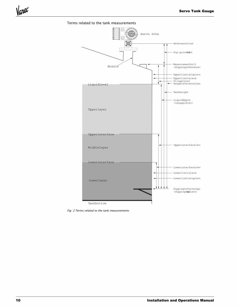
Terms related to the tank measurements
Fig. 2:Terms related to the tank measurements
Tankbottom
Lowerlayer
Middlelayer
Upperlayer
Upperinterface
Lowerinterface
Liquidlevel
Nozzle
Servo 600x
Referenceline
Dip-pointoffset
Upperlimitstopleve
UpperlimitalarmUllagelevelGaugereferenceleng
Tankheight
Upperinterfaceleve
Lowerinterfaceleve
Lowerlimitalarm
Lowerlimitstopleve
Dippingreferencepo(dippingdataplate)
Liquiddepth(innagelevel)
Measurementholt(dippingreference)
IOM007NVAE1103 11
6000
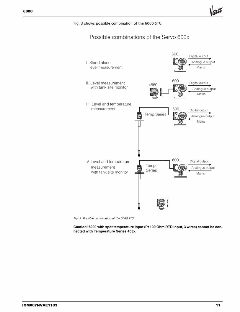
Fig. 3 shows possible combination of the 6000 STG
Fig. 3: Possible combination of the 6000 STG
Caution! 6000 with spot temperature input (Pt 100 Ohm RTD input, 3 wires) cannot be con-nected with Temperature Series 453x.
I. Stand alonelevel measurement
II. Level measurement with tank site monitor
III. Level and temperature measurement
IV. Level and temperature measurement with tank site monitor
TempSeries
Temp Series
4560
600...
600...
600...
600... Digital output
Digital output
Digital output
Digital output
Analogue output
Analogue output
Analogue output
Analogue output
Mains
Mains
Mains
Mains
Possible combinations of the Servo 600x
Servo Tank Gauge
12 Installation and Operations Manual
3. Specifications and Dimensions
3.1 Typical Specifications
Measuring range: 0 to 10/16/28 m
Density limits: 0.5 to 2.0 g/ml
Self-diagnostic function: measuring wire tension, level data input, and communications, status, computerdiagnostic, etc.
Liquid surface following speed: 0 to 2,500 mm/min. 0 to 99 sec.
Display: Backlight LCD, 2 lines; 16 characters/line(indicating level and temperature at the same time) (Japanese/English, selectable)
Operation: Via touch control (touch-sensitive keys) orexternal contact input
Calibration: Automated (changes in displacer weight andwire stretching automatically compensated)
Compensation: Compensation for tank distortion
Parts maintenance and management Information: Load ratio calculated from the quantity of
operation and operating ratio, then displayedand sent out as status information
Notepad function: Maintenance notepad
Accuracy: Liquid surface level: ±0.7 mm (densitydifference between two liquids 0.2g/ml;displacer diameter 50mm; measuring range10m)
Density: ±0.005 g/ml
Tank bottom: ±2.1 mm
Power requirements: high voltage type; 85 ... 264 V AC ,50/60 Hzlow voltage type; 20 ... 60 V DC / 20 ... 55 V
AC 50/60 Hz
Consumption: Max. 50 VA, 20W (cos j=0.5)
Lightning arrestor: Standard equipment
Temperature limits: -20 to +60 deg. C(environmental temperature)
Liquid-arrestor: -200 to +200 deg. C
Weight: 6531 STG/534: 12 kg6532 STG/536: 27 kg
IOM007NVAE1103 13
6000
Protection class: Ex d IIB T4, (TIIS)EEx d IIB T6, (PTB CENELEC)EEx d IIB T6 Zone0, (PTB CENELEC)XP Class1, Div.1, Gp.CD, (FM)Class1, Div.1, Gp.CD, (CSA)EEx d IIB T6, (ATEX)EEx d IIB T6 Zone0, (ATEX)EEx d[ia] IIB T6, (ATEX)EEx d[ia] IIB T6 Zone0, (ATEX)XP-AIS Class1, Div.1, Gp.CD, (FM)
Weights & Measuresrequirements approval: PTB (Germany), NMi (Netherlands)
Liquid leakage alarm requirements approval: TÜV Over Spill Protection (Germany)
Paint color: Body: light blue; Covers: lightgrey
Input/Output: External output: 4 to 20 mA, 4 contactoutputs, Bi-directional digital pulse two-wire transmission , RackbusRS485, Whessoe Matic 550, Mark/Space,HART, or Enraf Bi Phase Mark HARTExternal input/output: Local HART, 453x &4560, Status input Remote operation
Model name decoded Operating pressure1. Atmospheric pressure (0.2 g/cm2:Aluminium casting)2. Atmospheric pressure (0.2 g/cm2:Stainless steel)4. Middle pressure (6 kg/cm2: Aluminiumcasting)5. Middle pressure (6 kg/cm2: Stainless steel)6. High pressure (25 kg/cm2: Stainless steel)7. Sanitary version (Stainless steel)
Servo Tank Gauge
14 Installation and Operations Manual
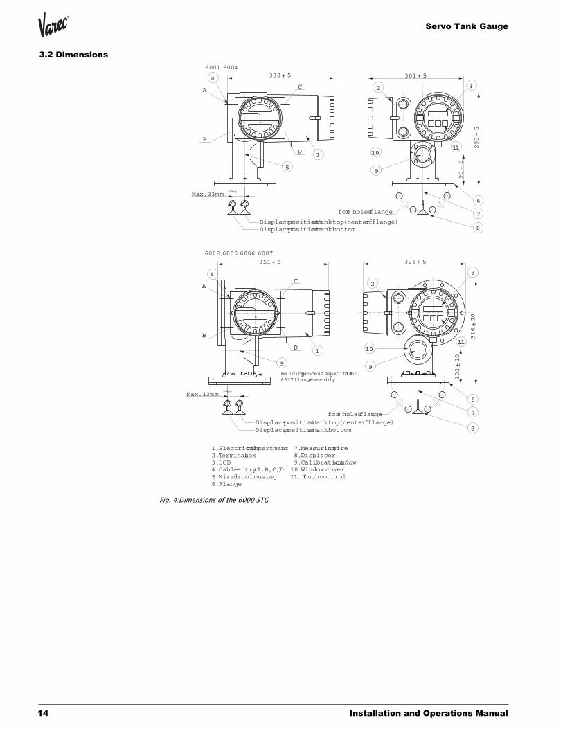
3.2 Dimensions
Fig. 4:Dimensions of the 6000 STG
1.Electricalcompartment2.Terminalbox3.LCD4.Cableentry(A,B,C,D)5.Wiredrumhousing6.Flange
7.Measuringwire8.Displacer9.Calibrationwindow10.Window cover11. Touchcontrol
Max.33mm
338± 5 301± 5
293±5
99±5
A
B
C
D
4
5
1
for8 holesflange
6
7
8
11111010
9
2 3
Displacerpositionattanktop(centerofflange)Displacerpositionattankbottom
6001 6004
6002,6005 6006 6007
8
Max.33mm6
7
1111
3
for8 holesflange
1010
9
2A
B
C
D
4
5
1
351± 5 321± 5
316±10
102±10
Displacerpositionattanktop(centerofflange)Displacerpositionattankbottom
We ldingprocessisspecified for6537flangeassembly
IOM007NVAE1103 15
6000
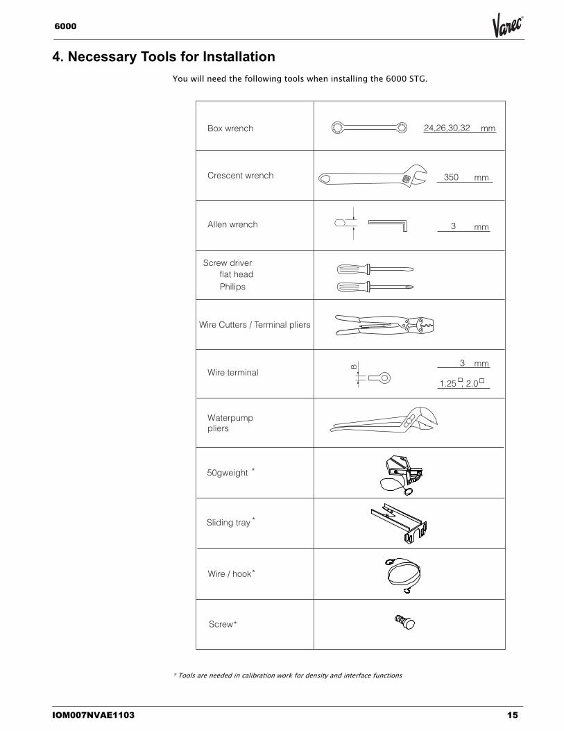
4. Necessary Tools for InstallationYou will need the following tools when installing the 6000 STG.
* Tools are needed in calibration work for density and interface functions
Box wrench
Crescent wrench
Allen wrench
Screw driver
Wire Cutters / Terminal pliers
Wire terminal
50gweight
Sliding tray
Wire / hook
Screw*
*
*
*
Waterpumppliers
mm
mm
mm
mmB
24,26,30,32
350
3
3
1.25 , 2.0
flat head Philips
Servo Tank Gauge
16 Installation and Operations Manual
5. MountingThe following installation procedures are available for the 6000 STG.
• Mounting without guide system.
• Mounting with stilling well (also called pipe)
• Mounting with guide wire
5.1 Application drawing for tanks
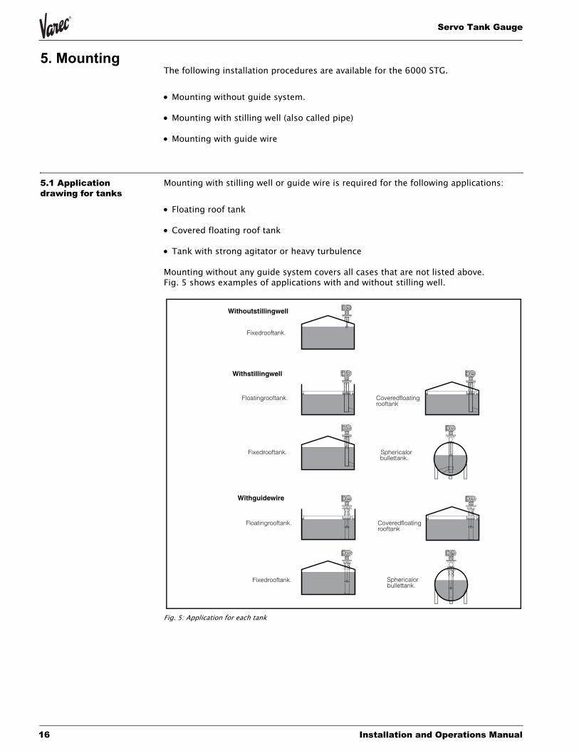
Mounting with stilling well or guide wire is required for the following applications:
• Floating roof tank
• Covered floating roof tank
• Tank with strong agitator or heavy turbulence
Mounting without any guide system covers all cases that are not listed above.Fig. 5 shows examples of applications with and without stilling well.
Fig. 5: Application for each tank
Floatingrooftank.
Fixedrooftank.
Withoutstillingwell
Fixedrooftank.
Withstillingwell
Coveredfloatingrooftank
Sphericalorbullettank.
Withguidewire
Floatingrooftank.
Fixedrooftank.
Coveredfloatingrooftank
Sphericalorbullettank.
IOM007NVAE1103 17
6000
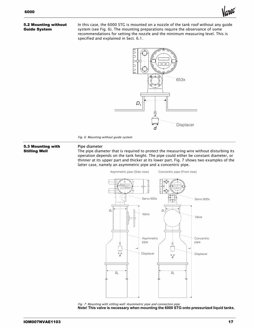
5.2 Mounting without Guide System
In this case, the 6000 STG is mounted on a nozzle of the tank roof without any guide system (see Fig. 6). The mounting preparations require the observance of some recommendations for setting the nozzle and the minimum measuring level. This is specified and explained in Sect. 6.1.
Fig. 6: Mounting without guide system
5.3 Mounting with Stilling Well
Pipe diameterThe pipe diameter that is required to protect the measuring wire without disturbing its operation depends on the tank height. The pipe could either be constant diameter, or thinner at its upper part and thicker at its lower part. Fig. 7 shows two examples of the latter case, namely an asymmetric pipe and a concentric pipe.
Fig. 7: Mounting with stilling well: Asymmetric pipe and connection pipeNote! This valve is necessary when mounting the 6000 STG onto pressurized liquid tanks.
Displacer
653x
ValveValve
Asymmetricpipe
Concentricpipe
Displacer Displacer
Servo 600xServo 600x
Asymmetric pipe (Side view) Concentric pipe (Front view)
Servo Tank Gauge
18 Installation and Operations Manual
Note! The 6000 STG must be mounted on the asymmetric pipe in the direction shown above.
To calculate the required pipe diameters, the formulae below should be used. The variables and constants have the following meanings:
D1 Inner diameter of the upper part of the pipe
D2 Inner diameter of the lower part of the pipe
L Length of the pipe (from the flange of the 6000 STG to bottom of the stilling well) ...meters
v Deviation of the pipe from the vertical per length
d Diameter of the displacer
e Lateral shift of the displacer per length due tothe groove of the wire drum (max.33 mm)
• Upper diameter
D1 > d + 10 mm
where D1 > 3" should be fulfilled. •Lower diameter
- Asymmetric pipe
D2 > d+ eL + 2vL+ 10mm
- concentric pipe
D2 > d + 2eL + 2vL + 10mm
Recommendations for mounting
Note! Observe the following recommendations for mounting with stilling well:
• Keep the pipe connection welds smooth.
• While drilling holes into the pipe, keep the interior surface of the holes clear of metal chips and burrs.
• Coat or paint the interior surface of the pipe to avoid rust.
• Keep the pipe as perfectly vertical as possible. Check this by a plumb.
• Install the asymmetric pipe under the valve and fit the centers of the Servo Tank Gauge and the valve.
• Set the center of the lower part of the asymmetric pipe to the direction of the displacer motion.
IOM007NVAE1103 19
6000
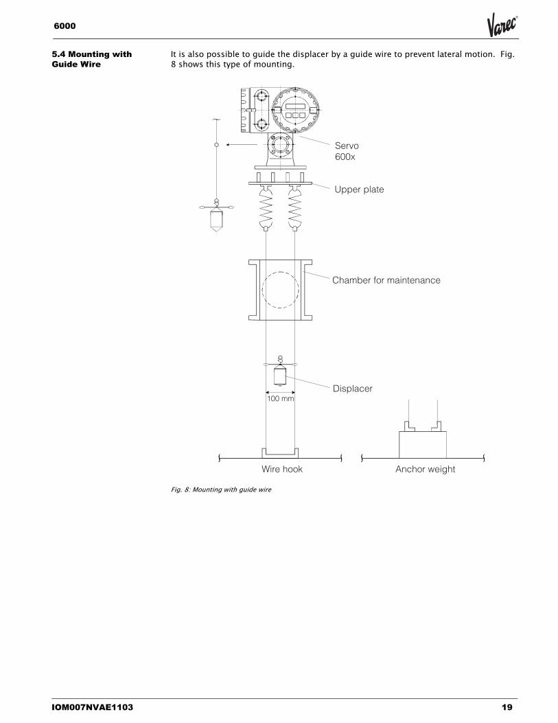
5.4 Mounting with Guide Wire
It is also possible to guide the displacer by a guide wire to prevent lateral motion. Fig. 8 shows this type of mounting.
Fig. 8: Mounting with guide wire
Upper plate
Servo600x
Chamber for maintenance
Displacer100 mm
Wire hook Anchor weight
Servo Tank Gauge
20 Installation and Operations Manual
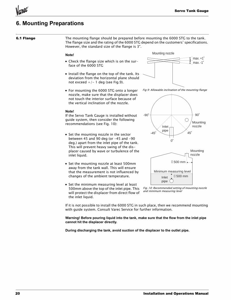
6. Mounting Preparations
6.1 Flange The mounting flange should be prepared before mounting the 6000 STG to the tank. The flange size and the rating of the 6000 STG depend on the customers’ specifications. However, the standard size of the flange is 3".
Note!
• Check the flange size which is on the sur-face of the 6000 STG
• Install the flange on the top of the tank. Its deviation from the horizontal plane should not exceed +/- 1 deg (see Fig.9).
• For mounting the 6000 STG onto a longer nozzle, make sure that the displacer does not touch the interior surface because of the vertical inclination of the nozzle.
Note! If the Servo Tank Gauge is installed without guide system, then consider the following recommendations (see Fig. 10):
• Set the mounting nozzle in the sector between 45 and 90 deg (or -45 and -90 deg.) apart from the inlet pipe of the tank. This will prevent heavy swing of the dis-placer caused by wave or turbulence of the inlet liquid.
• Set the mounting nozzle at least 500mm away from the tank wall. This will ensure that the measurement is not influenced by changes of the ambient temperature.
• Set the minimum measuring level at least 500mm above the top of the inlet pipe. This will protect the displacer from direct flow of the inlet liquid.
If it is not possible to install the 6000 STG in such place, then we recommend mounting with guide system. Consult Varec Service for further information.
Warning! Before pouring liquid into the tank, make sure that the flow from the inlet pipe cannot hit the displacer directly.
During discharging the tank, avoid suction of the displacer to the outlet pipe.
Mounting nozzlemax. +1˚max. -1˚
-90˚ 90˚
-45˚ 45˚
0˚
Inletpipe
Mountingnozzle
Mountingnozzle
≥ 500 mm
Minimum measuring level
≥ 500 mmInletpipe
Fig 9: Allowable inclination of the mounting flange
Fig. 10: Recommended setting of mounting nozzle and minimum measuring level
IOM007NVAE1103 21
6000
6.2 Electrostatic ChargeNote!
• If the liquid measured by the 6000 STG has a conductivity of less than 10-8 S/cm, it is quasi-nonconductive. In that case, we recommend to use a stilling well or guide wire made of conductive material. This will release the electrostatic charge on the liquid surface.
• Without stilling well and guide wire, a certain stilling time must be kept before the dis-placer touches the liquid surface (see Sect. 1).
Servo Tank Gauge
22 Installation and Operations Manual
7. Cable Connection The electrical connection of the 6000 STG is shown in Figs. 11 - 16.
Note! The power supply cable should have the following specifications:
• PVC, PE, or equivalently isolated
• 600 V insulation voltage or equivalent.
The size of the core will be defined by core resistance, voltage drop, and required power consumption. The maximum power consumption of the 6000 STG is 50 VA.
Caution! •Connect the ground line to the ground terminal inside or outside the terminal box.
IOM007NVAE1103 23
6000
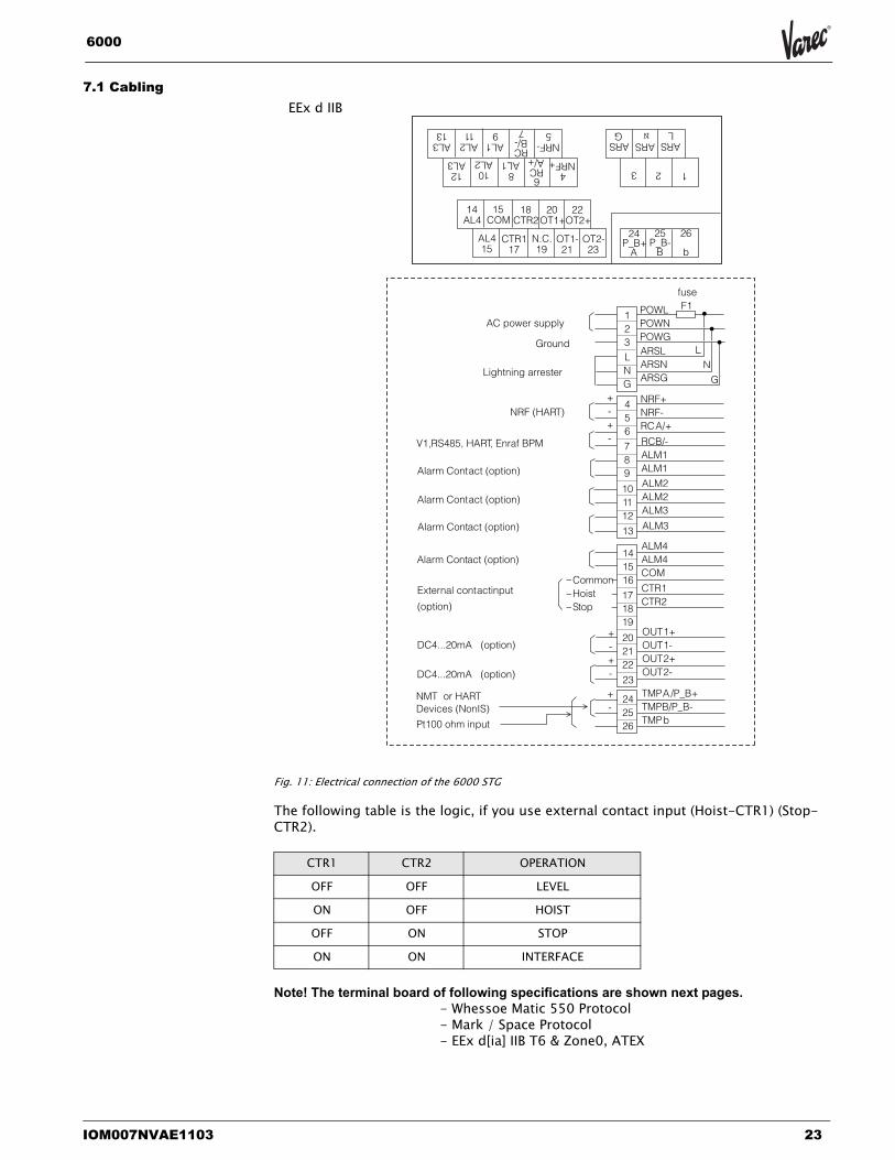
7.1 Cabling
Fig. 11: Electrical connection of the 6000 STG
The following table is the logic, if you use external contact input (Hoist-CTR1) (Stop-CTR2).
Note! The terminal board of following specifications are shown next pages.- Whessoe Matic 550 Protocol- Mark / Space Protocol- EEx d[ia] IIB T6 & Zone0, ATEX
CTR1 CTR2 OPERATION
OFF OFF LEVEL
ON OFF HOIST
OFF ON STOP
ON ON INTERFACE
14AL4
15COM
18CTR2
20OT1+
22OT2+
AL415
CTR117
N.C.19
OT1-21
OT2-23
4NRF+
8AL1
10AL2
12AL3
AL313
AL211
AL19
RCB/-7
NRF-5
6RCA/+
24P_B+
A
25P_B-
B
26
b
123
ARSL
ARSG
ARS
POWLPOWNPOWGARSLARSNARSG
NRF+NRF-RCA/+
RCB/-ALM1ALM1
ALM2ALM2ALM3
123LNG
AC power supply
242526
+-
+-+-
ALM3
141516
171819
202122
+-+-
23
456
789
101112
13ALM4ALM4COM
CTR1CTR2
OUT1+OUT1-OUT2+OUT2-
TMPA/P_B+TMPB/P_B-TMPb
fuseF1
LN
GLightning arrester
NRF (HART)
V1,RS485, HAR T, Enraf BPM
Alarm Contact (option)
Alarm Contact (option)
Alarm Contact (option)
External contactinput
(option)
Alarm Contact (option)
DC4...20mA (option)
DC4...20mA (option)
NMT or HARTDevices (NonIS)
CommonHoistStop
Ground
Pt100 ohm input
N
EEx d IIB

Servo Tank Gauge
24 Installation and Operations Manual
Fig. 12: Electrical connection of the 6000 STG with IS HART connection
14AL4
15COM
18CTR2
20OT1+
22OT2+
AL415
CTR117
N.C.19
OT1-21
OT2-23
4P_B+
8AL1
10AL2
12AL3
AL313
AL211
AL19
RCB/-7
P_B-5
6RCA/+
24P_A+
A
25P_A-
B
26
b
123
ARSL
ARSG
ARSN
POWL
POWN
POWG
ARSL
ARSN
ARSG
P_B+
P_B-
RC A/+
RCB/-
ALM1
ALM1
ALM2
ALM2
ALM3
1
2
3
L
N
G
AC power supply
24
25
26
+
-
+
-
+
-
ALM3
14
15
16
17
18
19
20
21
22
+
-
+
-23
4
5
6
7
8
9
10
11
12
13
ALM4
ALM4
COM
CTR1
CTR2
OUT 1+
OUT 1-
OUT 2+
OUT 2-
TMP A/P_A+
TMPB/P_A-
TMP b
fuse
F1
L
N
GLightning arrester
NRF or Non IS HAR T Devices
V1, RS485, HAR T, Enraf BPM
Alarm Contact (option)
Alarm Contact (option)
Alarm Contact (option)
External contact input(option)
Alarm Contact (option)
DC4...20mA (option)
DC4...20mA (option)
Common
Hoist
Stop
Ground
NMT or HARTDevices (IS)Pt100 ohm (IS) input
EEx d[ia] IIB
IOM007NVAE1103 25
6000
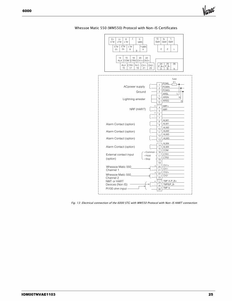
Fig. 13: Electrical connection of the 6000 STG with WM550 Protocol with Non-IS HART connection
14AL4
15COM
18CTR2
20Ch1+
22Oh2+
AL415
CTR117
N.C.19
Ch1-21
Oh2-23
4NRF+
8AL1
10AL2
12AL3
AL313
AL211
AL19 7
NRF-5
6
24P_B+
A
25P_B-
B
26
b
123
ARSL
ARSG
ARSN
POWL
POWN
POWG
ARSL
ARSN
ARSG
NRF+
NRF-
ALM1
ALM1
ALM2
ALM2
ALM3
1
2
3
L
N
G
ACpower supply
24
25
26
+
-
+
-
+
-
ALM3
14
15
16
17
18
19
20
21
22
+
-
+
-23
4
5
6
7
8
9
10
11
12
13
ALM4
ALM4
COM
CTR1
CTR2
Ch1+
Ch1-
Ch2+
Ch2-
TMP A /P_B+
TMPB/P_B-
TMP b
fuse
F1
L
N
GLightning arrester
NRF (HAR T)
Alarm Contact (option)
Alarm Contact (option)
Alarm Contact (option)
External contact input(option)
Alarm Contact (option)
Whessoe Matic 550Channel 1
Whessoe Matic 550Channel 2
Common
Hoist
Stop
Ground
Pt100 ohm input
NMT or HARTDevices (Non IS)
Whessoe Matic 550 (WM550) Protocol with Non-IS Certificates
Servo Tank Gauge
26 Installation and Operations Manual
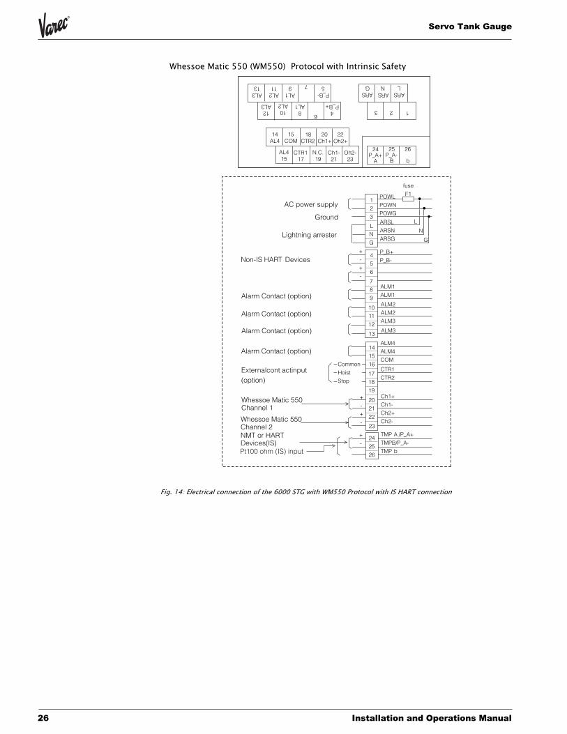
Fig. 14: Electrical connection of the 6000 STG with WM550 Protocol with IS HART connection
14AL4
15COM
18CTR2
20Ch1+
22Oh2+
AL415
CTR117
N.C.19
Ch1-21
Oh2-23
4P_B+
8AL1
10AL2
12AL3
AL313
AL211
AL19 7
P_B-5
6
24P_A+
A
25P_A-
B
26
b
123
ARSL
ARSG
ARSN
POWL
POWN
POWG
ARSL
ARSN
ARSG
P_B+
P_B-
ALM1
ALM1
ALM2
ALM2
ALM3
1
2
3
L
N
G
AC power supply
24
25
26
+
-
+
-
+
-
ALM3
14
15
16
17
18
19
20
21
22
+
-
+
-23
4
5
6
7
8
9
10
11
12
13
ALM4
ALM4
COM
CTR1
CTR2
Ch1+
Ch1-
Ch2+
Ch2-
TMP A /P_A+
TMPB/P_A-
TMP b
fuse
F1
L
N
GLightning arrester
Alarm Contact (option)
Alarm Contact (option)
Alarm Contact (option)
Externalcont actinput(option)
Alarm Contact (option)
Whessoe Matic 550Channel 1
Whessoe Matic 550Channel 2
Common
Hoist
Stop
Ground
NMT or HARTDevices(IS)
Non-IS HART Devices
Pt100 ohm (IS) input
Whessoe Matic 550 (WM550) Protocol with Intrinsic Safety
IOM007NVAE1103 27
6000
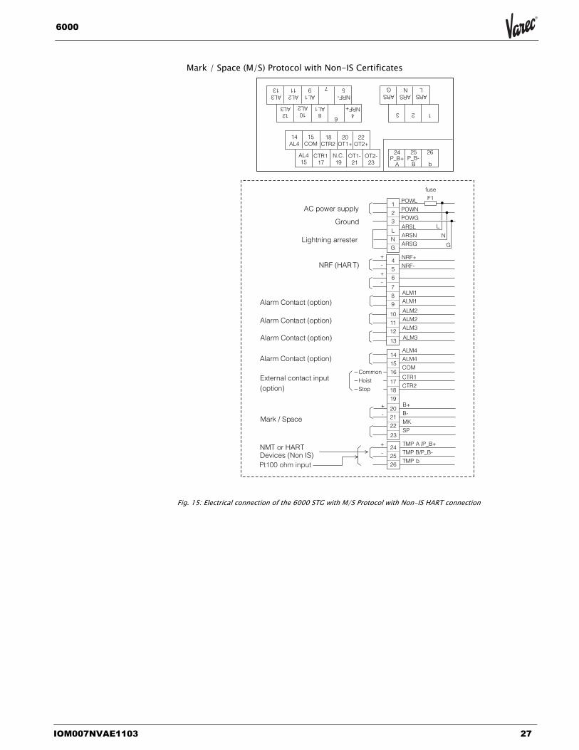
Fig. 15: Electrical connection of the 6000 STG with M/S Protocol with Non-IS HART connection
14AL4
15COM
18CTR2
20OT1+
22OT2+
AL415
CTR117
N.C.19
OT1-21
OT2-23
4NRF+
8AL1
10AL2
12AL3
AL313
AL211
AL19 7
NRF-5
6
24P_B+
A
25P_B-
B
26
b
123
ARSL
ARSG
ARSN
POWL
POWN
POWG
ARSL
ARSN
ARSG
NRF+
NRF-
ALM1
ALM1
ALM2
ALM2
ALM3
1
2
3
L
N
G
AC power supply
24
25
26
+
-
+
-
+
-
ALM3
14
15
16
17
18
19
20
21
22
+
-
23
4
5
6
7
8
9
10
11
12
13
ALM4
ALM4
COM
CTR1
CTR2
B+
B-
MK
SP
TMP A /P_B+
TMP B/P_B-
TMP b
fuse
F1
L
N
GLightning arrester
NRF (HAR T)
Alarm Contact (option)
Alarm Contact (option)
Alarm Contact (option)
External contact input(option)
Alarm Contact (option)
Common
Hoist
Stop
Ground
NMT or HARTDevices (Non IS)
Mark / Space
Pt100 ohm input
Mark / Space (M/S) Protocol with Non-IS Certificates
Servo Tank Gauge
28 Installation and Operations Manual
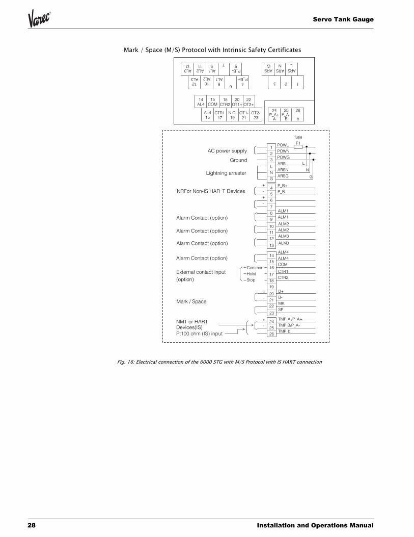
Fig. 16: Electrical connection of the 6000 STG with M/S Protocol with IS HART connection
14AL4
15COM
18CTR2
20OT1+
22OT2+
AL415
CTR117
N.C.19
OT1-21
OT2-23
4P_B+
8AL1
10AL2
12AL3
AL313
AL211
AL19 7
P_B-5
6
24P_A+
A
25P_A-
B
26
b
123
ARSL
ARSG
ARSN
POWL
POWN
POWG
ARSL
ARSN
ARSG
P_B+
P_B-
ALM1
ALM1
ALM2
ALM2
ALM3
1
2
3
L
N
G
AC power supply
24
25
26
+
-
+
-
+
-
ALM3
14
15
16
17
18
19
20
21
22
+
-
23
4
5
6
7
8
9
10
11
12
13
ALM4
ALM4
COM
CTR1
CTR2
B+
B-
MK
SP
TMP A /P_A+
TMP B/P_A-
TMP b
fuse
F1
L
N
GLightning arrester
NRFor Non-IS HAR T Devices
Alarm Contact (option)
Alarm Contact (option)
Alarm Contact (option)
External contact input(option)
Alarm Contact (option)
Common
Hoist
Stop
Ground
NMT or HARTDevices(IS)
Mark / Space
Pt100 ohm (IS) input
Mark / Space (M/S) Protocol with Intrinsic Safety Certificates

IOM007NVAE1103 29
6000
7.2 Input and output• V1 serial bus is used for the connection of the existing receiving system of Sakura
Endress or the tank farm where the distance from the tank site to the control room is max. 6 km.
• RS 485 with Rackbus protocol is used for normal applications together with other Varec products.
• Alarm contacts and external contact input analogue signal are available as optional output.
• A HART input is available where temperature sensor 453x Temperature product, tank site monitor Servo Monitor 4560, or other HART devices can be connected.
• A Pt100 ohm RTD input is available as optional input.
The cable used for input and/or output must be more than 24 AWG screened or steel armored. A twisted pair is required for the HART and/or RS 485 signal.
Two or three cores for mains, two cores for digital output, and two cores for HART input are normally used for the cabling of the 6000 STG. The instrument has max. four cable entries.
Before you place an order for the 6000 STG, please check the cable size and the number of cables.
7.3 Cable Gland If you do not use all the cable entries, then take out unnecessary glands and put the plug to the thread to prevent intrusion of water.

Servo Tank Gauge
30 Installation and Operations Manual
8. Displacer and Measuring Wire
8.1 Shape, Diameter, and Material
DisplacerThere are several types of displacer available for the 6000 STG:
• The standard type has cylindrical shape and a diameter of 50 mm. Diameters from 30 to 50 mm are optional (PTB Weights & Measures type is a diameter of 110 mm. NMi Weights & Weights type is a diameter of 70 mm)
• Cylindrical shape is used for sticky material. It is also effective if the stilling well has a burr on its interior surface.
Displacer weight and volume depend on the application. Thin displacers are suited for level measurement, thicker ones for bottom level, interface level, and density measurement.
A counterweight is optional for heavy turbulence. Displacers of three different materials are provided:
• The standard material is stainless steel SUS316.
• Hastelloy C and PTFE coated are optional for corrosive liquids.
• Solid PTFE, however, is not applied for flammable liquids.
Caution! The following size of displacer will be supplied, when you order the custody transfer approval.
NMi (Netherlands) Ø70 mmPTB (Germany) Ø 110 mm
Measuring wire
• The standard material of the measuring wire is stainless steel SUS 316 (Ø 0.15 mm).
• Hastelloy C (Ø 0.20 mm) and PTFE coated stainless steel SUS316 (Ø0.4 mm) are for corrosive liquids.
Caution! The following specification of measuring wire will be supplied, when you order the custody transfer approval.
SUS 316 (Ø 0.15 mm) for NMi and PTB.
IOM007NVAE1103 31
6000
9. Touch Control and Programming Matrix
9.1 Display and Operating Elements
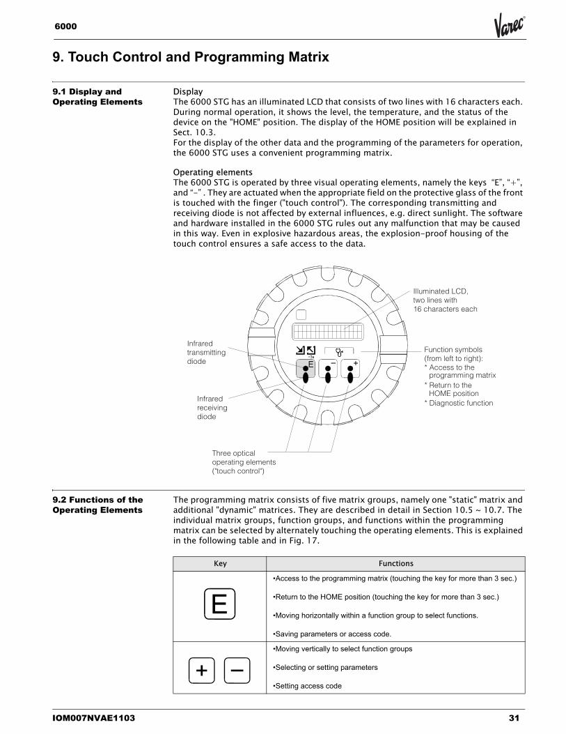
DisplayThe 6000 STG has an illuminated LCD that consists of two lines with 16 characters each. During normal operation, it shows the level, the temperature, and the status of the device on the "HOME" position. The display of the HOME position will be explained in Sect. 10.3.For the display of the other data and the programming of the parameters for operation, the 6000 STG uses a convenient programming matrix.
Operating elementsThe 6000 STG is operated by three visual operating elements, namely the keys “E”, “+”, and “-” . They are actuated when the appropriate field on the protective glass of the front is touched with the finger ("touch control"). The corresponding transmitting and receiving diode is not affected by external influences, e.g. direct sunlight. The software and hardware installed in the 6000 STG rules out any malfunction that may be caused in this way. Even in explosive hazardous areas, the explosion-proof housing of the touch control ensures a safe access to the data.
9.2 Functions of the Operating Elements
The programming matrix consists of five matrix groups, namely one "static" matrix and additional "dynamic" matrices. They are described in detail in Section 10.5 ~ 10.7. The individual matrix groups, function groups, and functions within the programming matrix can be selected by alternately touching the operating elements. This is explained in the following table and in Fig. 17.
Infraredtransmittingdiode
Infraredreceivingdiode
Three opticaloperating elements("touch control")
Illuminated LCD,two lines with16 characters each
Function symbols(from left to right):* Access to the
* Return to the
* Diagnostic function
programming matrix
HOME position
Key Functions
•Access to the programming matrix (touching the key for more than 3 sec.)
•Return to the HOME position (touching the key for more than 3 sec.)
•Moving horizontally within a function group to select functions.
•Saving parameters or access code.
•Moving vertically to select function groups
•Selecting or setting parameters
•Setting access code
Servo Tank Gauge
32 Installation and Operations Manual
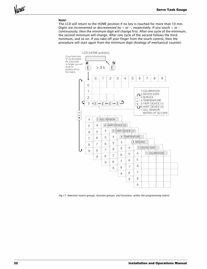
Note! The LCD will return to the HOME position if no key is touched for more than 10 min. Digits are incremented or decremented by + or -, respectively. If you touch + or - continuously, then the minimum digit will change first. After one cycle of the minimum, the second minimum will change. After one cycle of the second follows the third minimum, and so on. If you take off your finger from the touch control, then the procedure will start again from the minimum digit (Analogy of mechanical counter)
Fig.17: Selection matrix groups, function groups, and functions within the programming matrix
LCD (HOME position)
1 CALIBRATION2 DEVICE DATA3 SERVICE4 TEMPERATURE5 HART DEVICE (1)6 HART DEVICE (2)7 ADJ. SENSOR MATRIX OF G0 V3H0
If you touch any"E" on the matrixfor 3 secondsor longer, you willmove to position V0 on the matrix.
E E
E E E E +
_
> 3 s
0 1 2 3 987654
0
1
2
3
4
5
6
9
8
7
4
4
4
4
4
4
5
5
5
5
5
5
6
6
6
6
6
6
7
7
7
7
7
7
8
8
8
8
8
8
9
9
9
9
9
9
7 ADJ. SENSOR
6 HART DEVICE (2)
5 HART DEVICE (1)
4 TEMPERATURE
3 SERVICE
2 DEVICE DATA
1 CALIBRATION
IOM007NVAE1103 33
6000
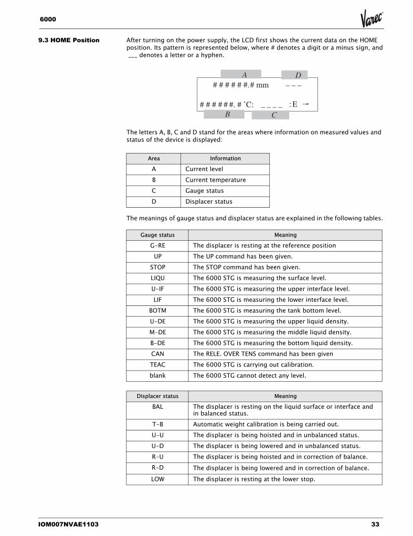
9.3 HOME Position After turning on the power supply, the LCD first shows the current data on the HOME position. Its pattern is represented below, where # denotes a digit or a minus sign, and ___ denotes a letter or a hyphen.
The letters A, B, C and D stand for the areas where information on measured values and status of the device is displayed:
The meanings of gauge status and displacer status are explained in the following tables.
Area Information
A Current levelB Current temperatureC Gauge statusD Displacer status
Gauge status Meaning
G-RE The displacer is resting at the reference positionUP The UP command has been given.
STOP The STOP command has been given.LIQU The 6000 STG is measuring the surface level.U-IF The 6000 STG is measuring the upper interface level.LIF The 6000 STG is measuring the lower interface level.
BOTM The 6000 STG is measuring the tank bottom level.U-DE The 6000 STG is measuring the upper liquid density.M-DE The 6000 STG is measuring the middle liquid density.B-DE The 6000 STG is measuring the bottom liquid density.CAN The RELE. OVER TENS command has been givenTEAC The 6000 STG is carrying out calibration.blank The 6000 STG cannot detect any level.
Displacer status Meaning
BAL The displacer is resting on the liquid surface or interface and in balanced status.
T-B Automatic weight calibration is being carried out.U-U The displacer is being hoisted and in unbalanced status.U-D The displacer is being lowered and in unbalanced status. R-U The displacer is being hoisted and in correction of balance.R-D The displacer is being lowered and in correction of balance.
LOW The displacer is resting at the lower stop.
Servo Tank Gauge
34 Installation and Operations Manual
Note! If no key is touched for more than 10 min., then the 6000 STG will turn off the back-lighting of the LCD to save energy, touching a key again after this time will turn on the backlighting.
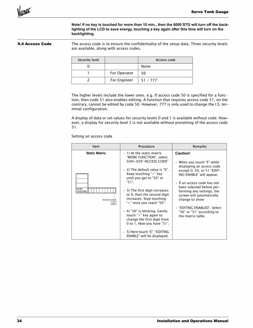
9.4 Access Code The access code is to ensure the confidentiality of the setup data. Three security levels are available, along with access codes.
The higher levels include the lower ones. e.g. If access code 50 is specified for a func-tion, then code 51 also enables editing. A function that requires access code 51, on the contrary, cannot be edited by code 50. However, 777 is only used to change the I.S. ter-minal configuration.
A display of data or set values for security levels 0 and 1 is available without code. How-ever, a display for security level 2 is not available without presetting of the access code 51.
Setting an access code
Security level Access code
0 None1 For Operator 50
2 For Engineer 51 / 777
Item Procedure Remarks
Static Matrix • 1) At the static matrix “MORE FUNCTION”, select GVH=039 “ACCESS CODE”
• 2) The default value is “0”. Keep touching “+” key until you get to “50” or “51”.
• 3) The first digit increases to 9, then the second digit increases. Stop touching “+” once you reach “50”.
• 4) “50” is blinking. Gently touch “+” key again to change the first digit from 0 to 1. Now you have “51”.
• 5) Here touch “E”; “EDITING ENABLE” will be displayed.
Caution!
• When you touch “E” while displaying an access code except 0, 50, or 51 “EDIT-ING ENABLE” will appear.
• If an access code has not been selected before per-forming any settings, the screen will automatically change to show
• “EDITING ENABLED”. Select “50” or “51” according to the matrix table.

IOM007NVAE1103 35
6000
9.5 Description of the Programming Matrix
The rows 0...3 of the programming matrix are called the static matrix. Its functions dis-play or allow programming of mainly measured values (primary variables) and basic operation of the 6000 STG.
The rows 4...9 exist on six different “pages” called the dynamic matrix. These matrix groups are labelled as follows;
STATIC MATRIX•STATIC (V0-V3) or DYNAMIC MATRIX (V0-V3)•CALIBRATION (G1V4-G1V9)•DEVICE DATA (G2V4-G2V9)•SERVICE (G3V4-G3V9)•TEMPERATURE (4V4-G4V9)•HART DEVICE (1) (G5V4-G5V9)•HART DEVICE (2) (G6V4-G6V9)•ADJ. SENSOR (G7V4-G7V9)* G = Group* V = Vertical* H = Horizontal
Their functions display or allow programming of parameters that are required for operation and commissioning of the 6000 STG, and/or the temperature 453x products. As already indicated in Fig. 17, the dynamic matrix is selected at position V3H0 (MATRIX OF) of the static matrix.
The individual functions of the matrix groups are described on the following pages.
The index number in the last column denotes matrix group (0 for the static matrix, 1...7 for the dynamic matrix), vertical position (or “FUNCTION GROUP”), and horizontal position (or “Item”) of the function.
9.6 Programming Matrix This section shows the complete programming matrix of the 6000 STG. Each matrix group appears on a separate page. The functions are described in the following way:
The access code is additionally indicated by the tint of the table cell:
Tint Access Code
none
50
51/777

Servo Tank Gauge
36 Installation and Operations Manual
NM
S53
xP
rog
ram
min
gM
atri
x(S
tati
cM
atri
x)
GR
OU
PM
ES
SA
GE
01
23
45
67
89
1600
0.00
mm
0.0
mm
0.0
mm
0.0
mm
0.0
mm
1.00
0g/
ml
1.00
0g/
ml
1.00
0g/
ml
0.0
mm
OF
F
ME
AS
UR
ED
VA
LUE
10
ME
AS
UR
ED
LEV
EL
ULL
AG
ELE
VE
LU
PP
ER
INT
ER
F.L
EVM
IDD
.IN
TE
RF
.LE
VB
OT
TO
MLE
VE
LU
PP
ER
DE
NS
ITY
MID
DLE
DE
NS
ITY
DE
NS
ITY
BO
TT
OM
LEV
EL
DA
TA
ST
AT
US
1
Dis
play
Dis
play
Dis
play
Dis
play
Dis
play
0.00
0-
3.00
0
Dis
play
/Set
(50)
0.00
0-
3.00
0
Dis
play
/Set
(50)
0.00
0-
3.00
0
Dis
play
/Set
(50)
Dis
play
ON
Dis
play
0.0o c
0.0o c
0m
m16
000.
0m
mm
m
ME
AS
UR
ED
VA
LUE
21
LIQ
UID
TE
MP
.D
EV
(1)
DE
V(2
)G
AS
TE
MP
ER
AT
UR
EZ
ER
OP
OIN
TS
PA
NLE
NG
TH
UN
IT
Dis
play
Dis
play
Dis
play
Dis
play
Dis
play
Dis
play
Dis
play
ST
OP
ST
OP
UN
BA
LAN
CE
DLE
VE
LLE
VE
L41
184
24
OP
ER
AT
ION
2O
PE
RA
TIO
N16
000
OP
ER
AT
ING
ST
AT
US
BA
LAN
CIN
GS
TA
TU
SO
PE
RA
T.B
YN
RF
OP
ER
AT
.BY
HO
ST
DE
VIC
EID
SO
FT
WA
RE
VE
RS
ION
See
belo
wop
erat
ion
com
man
ds
Sel
ect(
50)
See
belo
wst
atus
tabl
e
Dis
play
Dis
play
Dis
play
Dis
play
CA
LIB
RA
TIO
N98
627
8:21
:00
NO
ALA
RM
NO
ALA
RM
NO
ER
RO
RM
PU
:ST
AR
TA
CT
0
MO
RE
FU
NC
TIO
N3
MA
TR
IXO
FC
ALE
ND
ER
ALA
RM
CO
NT
AC
T0
LA0
00
0D
IAG
NO
ST
ICC
O0
9862
775
20
0A
CC
ES
SC
OD
E
Sel
ect
Cur
rect
data
Dis
play
Cur
rect
data
Dis
play
Cur
rect
data
Dis
play
Cur
rect
data
Dis
play
Cur
rect
data
Dis
play
0,5
0,51
,777
Set
VH
Def
ault
Dat
a
Dis
play
Tex
tPa
ram
eter
s,un
its, e
tc.
Mod
e (C
ode)

IOM007NVAE1103 37
6000
NM
S53x
Prog
ram
min
gM
atrix
(Dyn
amic
Mat
rix,C
alib
ratio
n:G
1)
GRO
UP
MES
SAG
E0
12
34
56
78
9
1600
0.0
mm
0.0
mm
10.0
mm
150
mm
150
mm
LEVE
LD
ATA
4TA
NK
HEI
GH
TD
IPPO
INT
OFF
SET
DIS
PLA
C.D
RAU
GH
TD
ISPL
.RAI
SED
ENS
DIS
PL.S
UBM
DIN
S.
0-9
9999
.9m
m
Set(
50)
0-
9999
9.9
mm
Set(
50)
0-9
99.9
mm
Set(
50)
0-3
00m
m
Set(
51)
0-1
500
mm
Set(
51)
1600
0.0
mm
0.0
mm
0.00
0m
m/m
CAL
IBRA
TIO
N5
SET
LEVE
LTA
NK
CO
RRE
CT
LEV
TAN
KC
ORR
E.C
OEF
0-9
9999
.9m
m
Set(
50)
0-9
9999
.9m
m
Set(
51)
0-5
9.99
9m
m/m
Set(
51)
1600
0m
m0
mm
350
g50
g60
mm
10m
m10
s10
s
ADJU
STM
ENT
6U
PPER
STO
PLO
WER
STO
PO
VER
TEN
S.SE
TU
ND
ERTE
NS.
SET
SLO
WH
OIS
TD
ISPL
.RAI
S.RE
P.D
ISPL
.WAI
TR
EP.
DIS
PL.W
AIT
DIP
0-9
9999
.9m
m
Set(
50)
0-9
9999
.9m
m
Set(
50)
0-9
99g
Set(
51)
0-9
99g
Set(
51)
60-1
800
mm
Set(
51)
10-9
9-+
mm
Set(
51)
10-9
99se
c.
Set(
51)
10-9
99se
c.
Set(
51)
NO
NE
9912
3123
Oho
urO
FF0.
0m
m0.
0m
m
AUTO
WIR
EC
ALIB
.7
CAL
IBR
.AU
TO/M
AN
STAR
TTI
ME
INTE
RVA
LTI
ME
AU
TOC
OM
PEN
SAT.
ZER
OC
ORR
ECTI
ON
CO
MPE
NS.
LIM
IT
MAN
UAL
AU
TOM
ATI
C
Set(
51)
0-9
9999
9
Set(
51)
0-9
999
hour
Set(
51)
ON
Set(
51)
0-9
9999
.9
Dis
play
(51)
0-9
9999
.9
Set(
51)
NO
NE
9912
3123
Oho
urO
FF0.
0g
0.0
g
AUTO
CAL
IB.D
ISPL
8C
ALIB
R.A
UTO
/MA
NST
ART
TIM
EIN
TER
VAL
TIM
EA
UTO
CO
MPE
NSA
T.D
EVIA
TIO
NC
OM
PEN
S.LI
MIT
MAN
UAL
AU
TOM
ATI
C
Set(
51)
0-9
9999
9
Set(
51)
0-9
999
hour
Set(
51)
ON
Set(
51)
0-9
99.9
Dis
play
(51)
0-9
9.9
Set(
51)
MEA
SURE
DLE
VEL
ENG
LISH
12
1513
59[.]
OFF
DIS
PLAY
9SE
LEC
TD
ISP.
MO
DE
LAN
GU
AG
ELC
DC
ON
TRA
STYE
ARSE
TTIN
GM
ON
THSE
TTIN
GD
AYSE
TTIN
GH
OU
RSE
TTIN
GM
INU
TESE
TTIN
GSE
LEC
TD
ECIM
ALLC
DC
HEC
K
ULL
AGE
LEVE
LM
EASU
RED
LEVE
L
Sele
ct(5
1)
JAPA
NES
E
Sele
ct(5
1)
0-1
5
Sele
ct(5
1)
0-9
9
Cur
rent
year
Set(
51)
0-1
2
Cur
rent
mon
thse
t(51
)
0-3
1
Cur
renn
tday
Set(
51)
0-2
3
Cur
rent
hour
Set(
51)
0-5
9
Cur
rent
min
ute
Set(
51)
, Sele
ct(5
1)
ON
Sele
ct(5
1)
VH

Servo Tank Gauge
38 Installation and Operations Manual
6000
ProgrammingMatrix(DynamicMatrix,DeviceData:G2)
GROUPMESSAGE
01
23
45
67
89
1N
ONE
HIGH
0mm
0mm
NORMAL
OPENED
0s
0s
CONTACTOUTPUT
4SELECT.RELAY
ASSIGNRELA
YRELAYFUNCTION
SWITCHING
POINT
HYSTERISIS
RELAYONALARM
ONDELAYTIME
OFFDELA
YTIME
Max4
Select(50)
LELVEL,
LIQUID
TEMP,
CAUTION,WARNING
EMEARGENCYERROR
BALA
NCESIGNAL
Select(50)
LOW
Select(50)
Max.99999
mm
Set
(50)
Max.9999mm
Set(50)
NORMAL
CLOSED
Set(50)
Max.999s
Set
(50)
Max.999s
Set
(50)
NONE
0mm
0mm
NONE
0mm
0mm
OFF
ANALOG
OUT.ADJUST
5ASSIGNOUTPUT1
ADJUST4mA
ADJUST20mA
ASSIGN
OUTPUT2
ADJUST4mA
ADJUST20mA
DEVICE
ATALARM
LEVEL
LIQUIDTEMP.
Select(50)
FORLIQUIDTEMP.
0.0
0C
Set
(50)
FORLIQUIDTEMP.
0.0
0C
Set
(50)
FORLIQUID
TEMP.
0.0
0 C
Set(50)
FORLIQUID
TEMP.
0.0
0 C
Set(50)
HOLD
CURNT.OUT
MAX
MINSelect(50)
1N
ONE
OPERATION
HOUR
1hour
0hour
NONE
NONE
POWERUNIT
PARTSDATA
6PARTSNUMBER
PARTSTYPE
MAINTEN.FACTOR
MAINTEN.VALUE
OPERATIONTIME
PH000
REPLACEDPARTS
MH
00
0
Max10
Select(51)
POWERUNIT,
DISPLA
Y,MOTOR
,WIRE,BEARINGS,
SHAFT,Select(51)
DRUM
REVOLT.
Select(51)
999999hour
Set
(51)
999999hour
Display(51)
POWERUNIT,
DISPLAY,MOTOR,
WIRE,BEARINGS,
SHAFT,Select(51)
POWERUNIT,
DISPLAY,MOTOR,
WIRE,BEARINGS,
SHAFT,Select(51)
NONE
OFF
DISABLED
84.24
4.00
1.00g/mL
0
INPUTSIGNAL
7OP
E.CONTACT
CUSTODYTRANSFER
NEWNMSSTATUS
SOFTWAREVERSION
HARDWAREVERSION
OPE.DENSITY
OPE.CONT.STATUS
ACTIVATED
Select(51)
Display
ENABLED
Select(51)
Display
Display
0-3.000
Set
(51)
2-256
Display(51)
HIGH
0.0mm
HIGH
0.0mm
0.0mm
0WM550,M/S
F0
COMMUNICATION
8LEVELALARM
1SETLEVELALARM1
LEVELALAR
M2
SETLEVELALARM2
HYSTERISYS
ADDRESS
PROT
OCOL
COMMU.LINEADJ.
COMMUNIC.STATUS
LOW
NONE
Select(51)
Max.99999.9mm
Select(51)
LOW
NONE
Select(51)
Max.99999.9mm
Set
(51)
Max.99999.9mm
Set(51)
0-FF
forMIC->FFfixed
Set(51)
BBB,MDP,V1,ENRA
F,
RACKBUS,HART
Select(51)
0-F
Set
(51)
Display(51)
0s
NONE
0s
STATUS
9STATUS1DELAY
SELECTCONTACT
BALA
NCEDELAY
~99s
Set
(51)
NORMALOPENED
NORMALCLOSED
Se lect(51)
~99s
Se t(51)
VH

IOM007NVAE1103 39
6000
NM
S53x
Prog
ram
min
gM
atrix
(Dyn
amic
Mat
rix,S
ervi
ce:G
3)
GR
OU
PM
ESSA
GE
01
23
45
67
89
300.
00m
m1.
4g
/10m
255.
0g
145.
0m
L60
mL
1.0
mL
20X
100
mS
0.00
mm
/m0
coun
t
MEA
S.W
IRE
&D
RU
M4
WIR
ED
RUM
CIR
C.
WIR
EW
EIG
HT
DIS
PLAC
ERW
EIG
HT
DIS
PLAC
ERVO
LUM
EBA
LAN
CE
VOLU
ME
VOLU
ME
TOLE
RAN
CE
DEL
AYD
RUM
CO
RREC
TIO
ND
ISPL
.HU
NT.
CO
UN
T
0-9
99.9
Set(
51)
0-9
99.9
Set(
51)
0-9
99.9
Set(
51)
0-9
99.9
Set(
51)
0-9
99.9
Set(
51)
0-9
9.9
Set(
51)
0-9
9
Set(
51)
0-9
9.00
Set(
51)
0-9
9
Set(
51)
OFF
OFF
0s
50m
mC
urre
ntD
ata
GA
UG
ED
ATA
5N
ON
HYS
TER
.MO
DE
HI.
AC
CU
RAC
YM
OD
EH
I.AC
CR.
OPE
.TIM
EH
I.AC
C.D
ISP.
UP
GAU
GE
TEM
P.
ON
Sele
ct(5
1)
ON
Sele
ct(5
1)
0-6
00
Set(
51)
0-3
00
Set(
51)
Dis
play
(51)
LOC
AL:M
AST
ERO
FFO
FFO
FF
SYST
EMD
ATA
6SE
NSO
RD
ATA
CO
NN
ECTI
ON
NRF
CO
NN
ECTI
ON
NM
TSO
FTRE
SET
REM
OTE
DC
OM
.ON
SOFT
WA
RE=
04.2
0H
ARD
WA
RE=T
CB
04G
EAR
1:36
NO
TO
VER
SPIL
L
CO
NTA
CT
1C
ON
TAC
T2
Sele
ct(5
1)
SPO
TTE
MP.
AVER
AGE
TEM
P.
Sele
ct(5
1)
ON
Sele
ct(5
1)
0.0
gO
FFO
FFO
FF70
mm
0.0
g
SERV
ICE
7M
EASU
RED
WEI
GH
TRE
LE.O
VER
TEN
SD
RUM
SETT
ING
WEI
GH
TC
ALIB
R.D
ISPL
.REF
EREN
CE
ZERO
ADJ.
WEI
GH
T
Dis
play
ON
Sele
ct(5
1)
ON
Sele
ct(5
1)
ON
Sele
ct(5
1)Se
t(51
)Se
t(51
)
Sa=2
1000
:A=2
1000
SEN
SOR
VALU
E8
Sb=1
1000
:B=1
1000
Dis
play
(51)
00
0.0g
00
0..0
g
SEN
SOR
DAT
A9
WT.
CO
UN
TC
ALA
WT.
CO
UN
TC
AL
B
Dis
play
(51)
Dis
play
(51)
VH

Servo Tank Gauge
40 Installation and Operations Manual
Sakura Endress
NM
S53
xP
rog
ram
min
gM
atri
x(D
ynam
icM
atri
x,T
emp
erat
ure
:G
4)
GR
OU
PM
ES
SA
GE
01
23
45
67
89
xxo C
zzo C
aaaa
.am
mV
H00
0.0
o C15
0.0
o C
TE
MP
ER
AT
UR
ED
AT
A4
LIQ
UD
TE
MP
.G
AS
TE
MP
ER
AT
UR
EM
EA
SU
RE
DLE
VE
LLE
V.D
AT
AS
ELE
CT
RE
FE
RE
NC
EZ
ER
OR
EF
ER
EN
CE
150
Cur
rent
data
Dis
play
(51)
Cur
rent
data
Dis
play
(51)
Cur
rent
data
Dis
play
(51)
VH
08
Sel
ect(
51)
Cur
rent
data
Dis
play
(51)
Cur
rent
data
Dis
play
(51)
aa.a
o Cbb
.bo C
cc.c
o Cdd
.do C
ee.e
o Cff.
fo Cgg
.go C
hh.h
o Chh
.ho C
jj.jo C
ELE
ME
NT
TE
MP
.5
TE
MP
.NO
.1T
EM
P.N
O.2
TE
MP
.NO
.3T
EM
P.N
O.4
TE
MP
.NO
.5T
EM
P.N
O.6
TE
MP
.NO
.7T
EM
P.N
O.8
TE
MP
.NO
.9T
EM
P.N
O.1
0
Cur
rent
data
Dis
play
(51)
Cur
rent
data
Dis
play
(51)
Cur
rent
data
Dis
play
(51)
Cur
rent
data
Dis
play
(51)
Cur
rent
data
Dis
play
(51)
Cur
rent
data
Dis
play
(51)
Cur
rent
data
Dis
play
(51)
Cur
rent
data
Dis
play
(51)
Cur
rent
data
Dis
play
(51)
Cur
rent
data
Dis
play
(51)
xxx.
xm
mxx
x.x
mm
xxx.
xm
mxx
x.x
mm
xxx.
xm
mxx
x.x
mm
xxx.
xm
mxx
x.x
mm
xxx.
xm
mxx
x.x
mm
ELE
ME
NT
PO
SIT
ION
6E
LEM
.1P
OS
ITIO
NE
LEM
.2P
OS
ITIO
NE
LEM
.3P
OS
ITIO
NE
LEM
.4P
OS
ITIO
NE
LEM
.5P
OS
ITIO
NE
LEM
.6P
OS
ITIO
NE
LEM
.7P
OS
ITIO
NE
LEM
.8P
OS
ITIO
NE
LEM
.9P
OS
ITIO
NE
LEM
.10
PO
SIT
ION
Cur
rent
data
Dis
play
(51)
Cur
rent
data
Dis
play
(51)
Cur
rent
data
Dis
play
(51)
Cur
rent
data
Dis
play
(51)
Cur
rent
data
Dis
play
(51)
Cur
rent
data
Dis
play
(51)
Cur
rent
data
Dis
play
(51)
Cur
rent
data
Dis
play
(51)
Cur
rent
data
Dis
play
(51)
Cur
rent
data
Dis
play
(51)
0x.
xo C
xx.x
o Cxx
x.x
mm
2
NM
TA
DJU
ST
ME
NT
7S
ELE
CT
PO
INT
ZE
RO
AD
JUS
TE
LEM
EN
TT
EM
PE
LEM
EN
TP
OS
ITIO
NA
VE
RA
GE
TIM
E
0-
15S
elec
tabl
eS
ELE
CT
PO
INT
+1
=E
LEM
EN
TN
o.S
et(5
1)S
et(5
1)
Cur
rent
data
Dis
play
(51)
Cur
rent
data
Dis
play
(51)
Set
(51)
016
5E
QU
AL
500.
0m
m20
00.0
mm
-49.
5o C
359.
0o C
SE
TD
AT
AN
MT
8D
IAG
NO
ST
ICT
OT
AL
NO
.ELE
ME
NTP
RE
AM
BLE
NU
MB
ER
KIN
DO
FIN
TE
RV
AL
BO
TT
OM
PO
INT
ELE
ME
NT
INT
ER
VA
LT
EM
P.E
LEM
.SH
OR
TT
EM
P.E
LEM
.OP
EN
Dis
play
(51)
2-
16
Set
(51)
1-
16
Set
(51)
UN
EQ
UA
L
Sel
ect(
51)
0.0
mm
to50
0.0
mm
valu
able
Set
(51)
Set
(51)
Dis
play
(51)
Dis
play
(51)
xxxx
xxO
FF
217
62
183
DE
VIC
ED
AT
AN
MT
9IN
ST
RU
ME
NT
CO
DE
LAS
TD
IAG
NO
ST
ICO
UT
PU
TA
TE
RR
OR
CU
ST
OD
YT
RA
NS
FE
RP
OLL
ING
AD
DR
ES
SM
AN
UF
AC
TU
RE
IDS
OF
TW
AR
EV
ER
SIO
NH
AR
DW
AR
EV
ER
SIO
ND
EV
ICE
TY
PE
CO
DE
Dis
play
(51)
Dis
play
(51)
Sel
ect(
51)
ON
Dis
play
(51)
Dis
play
(51)
Dis
play
(51)
Dis
play
(51)
Dis
play
(51)
181
Dis
play
(51)
VH

IOM007NVAE1103 41
6000
Sakura Endress
NM
S53x
Prog
ram
min
gM
atrix
(Dyn
amic
Mat
rix,H
AR
TD
EVIC
E(1
):G
5)
GR
OU
PM
ESSA
GE
01
23
45
67
89
OFF
MEA
SUR
EDVA
LUE
4PV
DAT
ASV
DAT
AH
ART
DEV
ICE
(1)
Dis
play
Dis
play
ON
LIQ
UID
TEM
P.G
ASTE
MPE
RAT
UR
ESe
lect
(51)
P.V.
SETT
ING
5P.
V.RA
NG
EU
NIT
P.V.
UPP
ERRA
NG
EP.
V.LO
WER
RAN
GE
DAM
PVA
LUE
Dis
play
(51)
Set(
51)
Set(
51)
Set(
51)
SEN
SOR
SPEC
IFIC
6SE
NSO
RSE
RIAL
NO
UPP
ERSE
NSO
RLM
TLO
WER
SEN
SOR
LMT
Dis
play
Dis
play
Dis
play
ALA
RM
7
SELF
DIA
GN
ISTI
C8
ERR
OR
CO
DE(
1)ER
ROR
CO
DE(
2)ER
ROR
CO
DE(
3)ER
ROR
CO
DE(
4)ER
ROR
CO
DE(
5)
Dis
play
Dis
play
Dis
play
Dis
play
Dis
play
4
DEV
ICE
DAT
A9
POLL
ING
ADD
RES
SM
AN
UFA
CTU
REID
DEV
ICE
TYPE
CO
DE
PREA
MBL
ESSO
FTW
ARE
VERS
ION
HAR
DW
ARE
VERS
IION
DEV
ICE
ID
FIXE
DAD
DRE
SS
Dis
play
Dis
play
Dis
play
Set
Dis
play
Dis
play
Dis
play
V
H

Servo Tank Gauge
42 Installation and Operations Manual
NM
S53x
Prog
ram
min
gM
atrix
(Dyn
amic
Mat
rix,H
ART
DEV
ICE
(2):
G6)
GR
OU
PM
ESSA
GE
01
23
45
67
89
OFF
MEA
SUR
EDVA
LUE
4PV
DAT
ASV
DA
TAH
ART
DEV
ICE
(2)
Dis
play
Dis
play
ON
GA
STE
MPE
RA
TUR
E
Sele
ct(5
1)
P.V.
SETT
ING
5P.
V.R
ANG
EU
NIT
P.V.
UPP
ERR
AN
GE
P.V.
LOW
ERR
AN
GE
DA
MP
VALU
E
Dis
play
(51)
Set(
51)
Set(
51)
Set(
51)
SEN
SOR
SPEC
IFIC
6SE
NSO
RSE
RIA
LN
OU
PPER
SEN
SOR
LMT
LOW
ERSE
NSO
RLM
T
Dis
play
Dis
play
Dis
play
ALAR
M7
SELF
DIA
GN
ISTI
C8
ERR
OR
CO
DE(
1)ER
RO
RC
OD
E(2)
ERR
OR
CO
DE(
3)ER
RO
RC
OD
E(4)
ERR
OR
CO
DE(
5)
Dis
play
Dis
play
Dis
play
Dis
play
Dis
play
5
DEV
ICE
DA
TA9
POLL
ING
AD
DR
ESS
MA
NU
FAC
TUR
EID
DEV
ICE
TYPE
CO
DE
PREA
MB
LES
SOFT
WA
RE
VER
SIO
NH
AR
DW
ARE
VER
SIIO
ND
EVIC
EID
FIXE
DA
DD
RES
S
Dis
play
Dis
play
Dis
play
Set
Dis
play
Dis
play
Dis
play
VH

IOM007NVAE1103 43
6000
Sakura Endress
NM
S53
xP
rog
ram
min
gM
atri
x(D
ynam
icM
atri
x,A
DJ.
SE
NS
OR
:G
7)
GR
OU
PM
ES
SA
GE
01
23
45
67
89
AD
J.S
EN
SO
R4
HA
RT
ER
RO
RR
AT
E5
UN
IT6
TE
RM
INA
LP
OR
TB
TE
RM
INA
LP
OR
TB
TE
RM
INA
LP
OR
TB
HA
RT
LIN
E7
NM
TH
AR
TD
EV
ICE
(1)
HA
RT
DE
VIC
E(2
)
TE
RM
INA
LP
OR
TA
Sel
ect(
777)
TE
RM
INA
LP
OR
TA
Sel
ect(
777)
TE
RM
INA
LP
OR
TA
Sel
ect(
777)
0.3
mL
150
150.
0m
m0.
0m
m
INT
ER
FA
CE
AD
JUS
T8
VO
L.T
OL.
FO
RI/F
BR
AK
ER
AT
EB
ALA
NC
EC
OU
NT
IF1
OF
FS
ET
IF2
OF
FS
ET
0-
99.9
mL
Set
(51)
0-
255
Set
(51)
0-
255
Set
(51)
0-
9999
.9m
m
Set
(51)
0-
9999
.9m
m
Set
(51)
NO
NE
9
VH

Servo Tank Gauge
44 Installation and Operations Manual
9.7 Description of the Programming Matrix
Mat
rixgr
oup
Func
tion
grou
pIte
mA
cces
sco
deSh
ortd
escr
iptio
nD
efau
ltva
ule
Set
Sele
ctD
ispl
ay
Poss
ible
setti
ngs,
sele
ctio
ns,o
rdis
play
sIn
dex
No,
GVH
STA
TIC
MAT
RIX
(Thi
sw
ord
isno
tsh
own)
MEA
SURE
DVA
LUE
1
MEA
SUR
EDLE
VEL
0
Mea
sure
din
nage
leve
l=Ta
nkH
eigh
t-ULL
AG
ELE
VEL
The
inna
gele
veli
sca
libra
ted
toth
em
anua
ldip
ping
leve
lat
posi
tion
GVH
=150
(SET
LEVE
L).T
heLC
Dsh
ows
the
disp
lace
rpos
ition
durin
gH
OIS
T,de
nsity
and
inte
rface
mea
sure
men
t,an
dca
libra
tion
1600
0.0
mm
Dis
play
0.0
...99
999.
9m
m00
0
ULL
AG
ELE
VEL
0
Mea
sure
dul
lage
leve
l=di
stan
cefro
mth
ePr
oser
voto
the
liqui
dsu
rface
-DIP
POIN
TO
FFSE
T.Th
eLC
Dsh
ows
the
disp
lace
rpos
ition
durin
gH
OIS
T,de
nsity
and
inte
rface
mea
sure
men
t,an
dca
libra
tion.
0.0
mm
Dis
play
0.0
...99
999.
9m
m00
1
UPP
ERIN
TER
F.LE
V0
Mea
sure
din
terfa
cele
velb
etw
een
two
liqui
ds.I
fliq
uid
laye
rsex
ists
,the
nth
ispo
sitio
nsh
ows
the
uppe
rint
erfa
cele
vel.
0.0
mm
Dis
play
0.0
...99
999.
9m
m00
2
MID
D.I
NTE
RF.L
EV0
Ifth
ree
liqui
dsex
ist,
then
this
posi
tion
show
sth
em
iddl
e(=
low
er)i
nter
face
leve
l.0.
0m
mD
ispl
ay0.
0...
9999
9.9
mm
003
BO
TTO
MLE
VEL
0M
easu
red
tank
botto
mor
botto
msl
udge
leve
l.0.
0m
mD
ispl
ay0.
0...
9999
9.9
mm
004
UPP
ERD
ENSI
TY50
Mea
sure
dor
setd
ensi
tyfo
rupp
erliq
uid
laye
r.M
anua
lset
ting
ispo
ssib
le,b
utth
ese
tval
uew
illbe
over
writ
ten
afte
rden
sity
mea
sure
men
t.1.
000
g/m
lD
ispl
ay/
Set
0.00
0...
3.00
0g/
ml
005
MID
DLE
DEN
SITY
50M
easu
red
orse
tden
sity
form
iddl
eliq
uid
laye
r.M
anua
lset
ting
ispo
ssib
le,b
utth
ese
tval
uew
illbe
over
writ
ten
afte
rden
sity
mea
sure
men
t.1.
000
g/m
lD
ispl
ay/
Set
0.00
0...
3.00
0g/
ml
006
DEN
SITY
BO
TTO
M50
Mea
sure
dor
setd
ensi
tyfo
rbot
tom
liqui
dla
yer.
Man
uals
ettin
gis
poss
ible
,but
the
setv
alue
will
beov
erw
ritte
naf
terd
ensi
tym
easu
rem
ent.
1.00
0g/
ml
Dis
play
/Se
t0.
000
...3.
000
g/m
l00
7
LEVE
LD
ATA
0Sa
me
asM
EASU
RED
LEVE
Lho
wev
er,t
hela
stm
easu
red
valu
eis
held
durin
gH
OIS
T,de
nsity
and
inte
rface
mea
sure
men
t,an
dca
libra
tion.
1600
0.0
mm
Dis
play
0.00
0...
3.00
0g/
ml
008
STAT
US1
0If
ade
vice
with
stat
usou
tput
isco
nnec
ted
like
oild
etec
tor
unit,
STA
TUS1
ON
orO
FFas
alar
msi
gnal
.For
conf
igur
atio
n,pl
ease
refe
rdyn
amic
mat
rixG
VH=2
90,2
91.
OFF
Dis
play
OFF
/ON
009

IOM007NVAE1103 45
6000
Mat
rixgr
oup
Func
tion
grou
pIte
mA
cces
sco
deSh
ortd
escr
iptio
nD
efau
ltva
ule
Set
Sele
ctD
ispl
ay
Poss
ible
setti
ngs,
sele
ctio
ns,o
rdis
play
sIn
dex
No,
GVH
STA
TIC
MAT
RIX
(Thi
sw
ord
isno
tsh
own)
MEA
SURE
DVA
LUE
2LI
QU
IDTE
MP.
0If
ate
mpe
ratu
rebu
lbis
conn
ecte
d,th
enth
ispo
sitio
nsh
ows
the
mea
sure
dliq
uid
tem
pera
ture
.Oth
erw
ise
the
LCD
will
bebl
ank.
0.0
°CD
ispl
ay-4
9.9
...24
9.9
°C01
0
(Prim
ary
Varia
ble
Dat
a)0
Dis
play
ofth
em
osti
mpo
rtant
varia
ble
disp
laye
don
orm
easu
red
byth
eco
nnec
ted
HA
RT
devi
ce.
Dis
play
0.0
...99
999.
9m
m01
1
(Sec
onda
ryVa
riabl
eD
ata
Dis
play
ofth
ese
cond
ary
impo
rtant
varia
ble
disp
laye
don
orm
easu
red
byth
eco
nnec
ted
HA
RT
devi
ce.
Dis
play
0.0
...99
999.
9m
m01
2
GA
STE
MPE
RAT
UR
E0
Ifa
tem
pera
ture
bulb
isco
nnec
ted,
then
this
posi
tion
show
sth
em
easu
red
gas
tem
pera
ture
.0.
o°C
Dis
play
-49.
9...
249.
9°C
013
ZER
OPO
INT
0Ze
ropo
intf
orC
OM
MU
WIN
IIba
rgra
ph.
0.0
mm
Dis
play
0.0
...99
999.
9m
m01
7
SPA
N0
Span
forC
OM
MU
WIN
IIba
rgra
ph.
1600
0.0
mm
Dis
play
0.0
...99
999.
9m
m01
8
LEN
GTH
UN
IT0
Span
forC
OM
MU
WIN
IIba
rgra
ph.
Dis
play
mm
l01
9
OPE
RATI
ON
OPE
RA
TIO
N(fr
omop
tical
key)
50O
pera
tion
ofth
edi
spla
cer.
Sele
ctio
nof
mea
surin
gfu
nctio
ns.
The
posi
tion
ofth
edi
spla
ceri
ssh
own
onth
eLC
D.
STO
PD
ispl
ayLE
VEL
UP
STO
P02
0

Servo Tank Gauge
46 Installation and Operations Manual
Sakura Endress
Ma
trix
gro
up
Fun
ctio
ng
rou
pIte
mA
cc
ess
co
de
Sho
rtd
esc
riptio
nD
efa
ult
vau
leSe
tSe
lec
tD
isp
lay
Poss
ible
setti
ng
s,se
lec
tions
,or
dis
pla
ysIn
de
xN
o,
GV
H
STA
TIC
MAT
RIX
(Thi
sw
ord
isno
tsh
own)
OPE
RATI
ON
OPE
RA
TIN
GST
ATU
S0
Dis
plac
erop
erat
ion
mod
eor
posi
tion
stat
usof
the
Pros
ervo
.Fo
rnew
oper
atio
nst
atus
plea
sere
ferm
atrix
posi
tion
GVH
=272
and
Appe
ndix
.ST
OP
Dis
play
REF
EREN
CE
UP
DO
WN
STO
PLE
VEL
BO
TTO
MLE
VEL
UPP
ERIN
TER
F.LE
V*M
IDD
INTE
RF.
LEV*
UPP
ERD
ENSI
TY*
MID
DLE
DEN
SITY
*D
ENSI
TYB
OTT
OM
*R
ELE.
OVE
RTE
NS
WEI
GH
TC
ALI
BR.
021
BAL
AN
CE
STA
TUS
0B
alan
cing
stat
usof
the
disp
lace
r.W
hen
the
disp
lace
rca
tche
sa
prod
uctl
evel
orin
terfa
cele
vel,
the
LCD
will
show
BA
LAN
CED
.U
NB
ALA
NC
EDD
ispl
ayB
ALAN
CED
UN
BA
LAN
CED
022
OPE
RA
T.B
YN
RF
0D
ispl
acer
oper
atio
nfro
mth
ePr
omon
itorN
RF5
60.
LEVE
LD
ispl
ay
LEVE
LU
PST
OP
BO
TTO
MLE
VEL
UPP
ERIN
TER
F.LE
VM
IDD
.INTE
RF.
LEV
UPP
ERD
ENSI
TYM
IDD
LED
ENSI
TYD
ENSI
TYB
OTT
OM
REP
EATA
BIL
ITY
WAT
ERD
IP
024

IOM007NVAE1103 47
6000
Sakura Endress
Ma
trix
gro
up
Fun
ctio
ng
rou
pIte
mA
cc
ess
co
de
Sho
rtd
esc
riptio
nD
efa
ult
vau
leSe
tSe
lec
tD
isp
lay
Poss
ible
setti
ng
s,se
lec
tions
,or
dis
pla
ysIn
de
xN
o,
GV
H
STA
TIC
MAT
RIX
(Thi
sw
ord
isno
tsh
own)
OPE
RATI
ON
OPE
RA
T.B
YH
OST
0D
ispl
acer
oper
atio
nfro
ma
host
syst
emi.e
.NXS
310,
NR
30(M
DP-
II),N
RS,
NRM
,CO
MM
UW
INII,
Fuel
sMan
ager
,et
c.LE
VEL
Dis
play
LEVE
LU
PST
OP
BO
TTO
MLE
VEL
UPP
ERIN
TER
F.LE
VM
IDD
.INTE
RF.
LEV
UPP
ERD
ENSI
TYM
IDD
LED
ENSI
TYD
ENSI
TYB
OTT
OM
REP
EATA
BIL
ITY
WAT
ERD
IP
025
DEV
ICE
ID0
Dis
play
sa
devi
ceID
411
Dis
play
028
SOFT
WA
RE
ID0
Dis
play
sa
softw
are
ID84
24D
ispl
ay02
9
MO
REFU
NC
TIO
N
MA
TRIX
OF
0Se
lect
ion
ofth
edy
nam
icm
atrix
ofth
epr
ogra
mm
ing
mat
rixC
ALIB
RAT
ION
Sele
ct
CAL
IBR
ATI
ON
DEV
ICE
DA
TASE
RVI
CE
TEM
PER
ATU
RE
HAR
TD
EVIC
E(1
)H
ART
DEV
ICE
(2)
AD
J.SE
NSO
R
030
(Cal
enda
r)0
Cal
enda
rand
cloc
kw
ithou
tday
light
savi
ngsy
stem
.N
OT
TRA
NSF
ERRE
DBY
RA
CKB
US.
Japa
nese
loca
ltim
eD
ispl
aye.
g.1
410
19:1
0:41
Year
Mon
thD
ayH
H:M
M:S
S03
3
ALA
RM
CO
NTA
CT
0A
larm
mes
sage
disp
lay,
depe
ndin
gon
curre
ntco
nditi
ons.
Dis
play
Ala
mm
essa
ge03
4
(Ala
rmM
essa
ge)
0Pr
evio
usal
arm
with
mes
sage
.O
nly
the
last
alar
mco
deis
trans
mitt
edby
Rack
bus.
Dis
play
Ala
rmm
essa
ge(re
fert
oat
tach
edta
ble)
035
DIA
GN
OST
ICC
O0
Self
diag
nosi
sat
the
mom
ent
Dis
play
Erro
rmes
sage
(refe
rto
atta
ched
tabl
e)03
6

Servo Tank Gauge
48 Installation and Operations Manual
Sakura Endress
Ma
trix
gro
up
Fun
ctio
ng
rou
pIte
mA
cc
ess
co
de
Sho
rtd
esc
riptio
nD
efa
ult
vau
leSe
tSe
lec
tD
isp
lay
Poss
ible
setti
ng
s,se
lec
tions
,or
dis
pla
ysIn
de
xN
o,
GV
H
STA
TIC
MAT
RIX
(Thi
sw
ord
isno
tsh
own)
MO
REFU
NC
TIO
N(E
rrone
ous
Mes
sage
)0
Prev
ious
alar
mw
ithm
essa
ge.
Onl
yth
ela
stal
arm
code
istra
nsm
itted
byRa
ckbu
s.(E
rrone
ous
Dat
e)D
ispl
ayEr
rorm
essa
ge(re
fert
oat
tach
edta
ble)
037
AC
CES
SC
OD
E0
Acc
ess
code
forp
rogr
amm
ing
(see
Sec.
10.4
)0
Set
0...
9999
039
CA
LIB
RA
TIO
NLE
VEL
DA
TATA
NK
HEI
GH
T50
Elev
atio
nle
velo
fthe
man
uald
ippi
ngre
fere
nce.
This
leve
lis
norm
ally
cons
ider
edas
tank
heig
htor
dip
poin
tre
fere
nce.
1600
0.0
mm
Set
0...
9999
9.9
mm
140
DIP
POIN
TO
FFSE
T50
Def
eren
cebe
twee
nel
evat
ion
ofth
ere
fere
nce
line
ofth
ePr
oser
voN
MS5
/7an
ddi
ppin
gre
fere
nce
(TA
NK
HEI
GH
T).
0.0
mm
Set
-999
99.9
...99
999.
9m
m14
1
DIS
PLA
CER
DR
AUG
HT
50D
raug
htof
the
disp
lace
r.Th
isva
lue
isus
edfo
rcal
ibra
tion
ofth
ePr
oser
voN
MS5
/7,w
hen
the
tank
isem
pty.
10.0
mm
Set
0.0
...99
9.9
mm
142
DIS
PL.R
AIS
DEN
S51
Valu
eof
the
disp
lace
rhoi
sted
from
surfa
ceor
inte
rface
whe
nde
nsity
mea
sure
men
tis
activ
ated
.15
0m
m..
Set
0...
300
mm
143
DIS
PL.S
UB
MD
ENS.
Valu
efo
rthe
disp
lace
rlow
ered
from
surfa
ceor
inte
rface
whe
nde
nsity
mea
sure
men
tis
activ
ated
.15
0m
m..
Set
0...
1500
mm
144
CA
LIBR
ATI
ON
SET
LEVE
L50
Cal
ibra
tion
orse
tting
ofle
veld
ata.
Leve
lind
icat
ion
can
bese
tto
man
uald
ippi
ngor
othe
rdat
ain
this
mod
e.Th
edi
ppo
int
offs
etw
illbe
chan
ged
acco
rdin
gto
the
seth
ere.
1600
0.0
mm
Set
0.0
...99
999.
9m
m15
0
TAN
KC
OR
REC
TLE
V51
Star
tlev
elfo
rtan
kro
ofco
mpe
nsat
ion
byle
vel.
This
com
pens
atio
nis
requ
ired
inca
seof
tank
roof
dist
ortio
ndu
eto
hydr
osta
ticpr
essu
reon
the
tank
wal
l.0.
0m
mSe
t0.
0...
9999
9.9
mm
152
TAN
KC
OR
RE.C
OEF
51Li
near
coef
ficie
ntfo
rtan
kro
ofco
mpe
nsat
ion
byle
vel.
0.00
0m
m7m
Set
0.00
0...
59.9
99m
m/m
153
AD
JUST
MEN
TU
PPER
STO
P50
Upp
erlim
itof
disp
lace
rmot
ion.
1600
0m
mSe
t0
...99
999
mm
160
LOW
ERST
OP
50Lo
wer
limit
ofdi
spla
cerm
otio
n.0
mm
Set
0...
9999
9m
m16
1
SET
OVE
RTE
NS.
51O
vert
ensi
onva
lue
ofth
em
easu
ring
wire
.Ift
hete
nsio
nex
ceed
sth
isva
lue,
then
the
Pros
ervo
stop
sop
erat
ion,
and
aner
rorm
essa
gew
illbe
disp
laye
d.35
0g
Set
0...
999
g16
2

IOM007NVAE1103 49
6000
Mat
rixgr
oup
Func
tion
grou
pIte
mA
cces
sco
deSh
ortd
escr
iptio
nD
efau
ltva
ule
Set
Sele
ctD
ispl
ay
Poss
ible
setti
ngs,
sele
ctio
ns,o
rdis
play
sIn
dex
No,
GVH
CA
LIB
RA
TIO
NA
DJU
STM
ENT
SET
UN
DER
TEN
S.51
Und
erte
nsio
nva
lue
ofth
em
easu
ring
wire
.Ift
hete
nsio
nfa
llsbe
low
this
valu
e,th
enth
ePr
oser
vost
ops
oper
atio
n,an
dan
erro
rmes
sage
will
bedi
spla
yed.
50g
Set
0...
999
g16
3
SLO
WH
OIS
T51
Slow
spee
dho
istin
gof
the
disp
lace
rto
avoi
dth
edi
spla
cer
hitti
ngth
eop
enin
gof
the
mou
ntin
gno
zzle
.Ift
hesi
zeof
the
nozz
leis
less
than
oreq
ualt
o3"
then
sett
heva
lue
grat
erth
anth
ele
ngth
ofth
eno
zzle
+60
mm
.
60m
mSe
t60
...18
00m
m16
4
DIS
PL.R
AIS
.REP
.51
Seta
hois
tdis
tanc
efo
rdis
plac
erun
derr
epea
tabi
lity
test
ing.
10m
mSe
t10
...99
mm
165
DIS
PL.W
AIT
REP
.51
Seta
wai
ting
time
ford
ispl
acer
mov
emen
tafte
rhoi
stup
unde
rrep
eata
bilit
yte
stin
g.10
sSe
t10
...99
9s
166
DIS
PL.W
AIT
DIP
.51
Seta
wai
ting
time
ford
ispl
acer
mov
emen
tbac
kto
leve
lm
easu
rem
entu
nder
wat
erdi
ppin
gfu
nctio
n.10
sSe
t10
...99
9s
167
AU
TOW
IRE
CAL
IB.
CAL
IBR
.AU
TO/M
AN
.51
Wire
leng
thca
libra
tion.
Whe
nM
AN
UA
Lis
sele
cted
,the
Pros
ervo
hois
tsth
ew
irein
the
drum
hous
ing,
and
then
mea
sure
sth
eliq
uid
surfa
ceag
ain.
By
AUTO
,the
Pros
ervo
hois
tsth
ew
irein
acco
rdan
cew
ithse
tSTA
RTTI
ME
and
INTE
RVA
LTI
ME.
NO
NE
Set
NO
NE
MA
NU
AL
AU
TOM
ATI
C17
0
STAR
TTI
ME
51St
artt
ime
ofw
ireca
libra
tion
whe
nAU
TOm
ode
isse
lect
ed.
Set
e.g.
1231
23m
onth
date
time
(hou
r)17
1
INTE
RVA
LTI
ME
51In
terv
alof
wire
calib
ratio
nw
hen
AU
TOm
ode
asse
lect
ed.
0ho
urSe
lect
0...
9999
hour
172
AU
TOC
OM
PEN
SAT.
51A
utom
atic
com
pens
atio
nof
leng
thda
ta.
OFF
Dis
play
OFF
ON
173
ZER
OC
OR
REC
TIO
N51
Zero
corre
ctio
nof
leng
thw
hen
the
wire
isho
istin
gfro
mth
eliq
uid.
0.0
mm
Dis
play
0...
9999
9.9
mm
174
CO
MPE
NS.
LIM
IT51
Allo
wab
lede
viat
ion
ofle
vela
fterl
evel
calib
ratio
n.If
the
devi
atio
nex
ceed
sth
ese
tval
ue,t
hen
anal
arm
will
beem
itted
.0.
0m
mSe
t0.
0...
9999
9.9
mm
175

Servo Tank Gauge
50 Installation and Operations Manual
Sakura Endress
Ma
trix
gro
up
Fun
ctio
ng
rou
pIte
mA
cc
ess
co
de
Sho
rtd
esc
riptio
nD
efa
ult
vau
leSe
tSe
lec
tD
isp
lay
Poss
ible
setti
ng
s,se
lec
tions
,or
dis
pla
ysIn
de
xN
o,
GV
H
CA
LIB
RA
TIO
NA
UTO
CA
LIB
.DIS
PL.
CAL
IBR
.AU
TO/M
AN
.51
Dis
plac
erw
eigh
tcal
ibra
tion.
Whe
nM
AN
UA
Lis
sele
cted
,the
Pros
ervo
hois
tsth
edi
spla
ceri
nth
ega
sph
ase,
once
chec
ksits
wei
ght,
and
then
mea
sure
sth
eliq
uid
surfa
ceag
ain.
By
AU
TO,t
hePr
oser
voho
ists
the
disp
lace
rin
acco
rdan
cew
ithse
tSTA
RT
TIM
Ean
dIN
TER
VAL
TIM
E.
NO
NE
Set
NO
NE
MA
NU
AL
AU
TOM
ATI
C18
0
STAR
TTI
ME
51St
artt
ime
ofw
eigh
tcal
ibra
tion
whe
nA
UTO
mod
eis
sele
cted
.Se
te.
g.12
3123
mon
thda
tetim
e(h
our)
181
INTE
RVA
LTI
ME
51In
terv
alof
wei
ghtc
alib
ratio
nw
hen
AU
TOm
ode
asse
lect
ed.
0ho
urSe
lect
0...
9999
hour
182
AU
TOC
OM
PEN
SAT.
51A
utom
atic
com
pens
atio
nof
wei
ghtd
ata.
OFF
Dis
play
OFF
ON
183
DEV
IATI
ON
51D
evia
tion
ofw
eigh
twhe
nth
edi
spla
ceri
sho
istin
gfro
mth
eliq
uid.
0.0
gD
ispl
ay0.
0...
99.9
g18
4
CO
MPE
NS.
LIM
IT51
Allo
wab
lede
viat
ion
ofw
eigh
tafte
rwei
ghtc
alib
ratio
n.If
"CA
UTI
ON
"has
been
sele
cted
onG
VH=2
41,a
ndth
ede
viat
ion
exce
eds
the
setv
alue
and
alar
mw
illbe
emitt
ed.
0.0
gSe
t0.
099
.9g
185
DIS
PLA
YSE
LEC
TD
ISP.
MO
DE
51Se
lect
ion
ofle
veld
ispl
ayat
HO
ME
posi
tion:
inna
geor
ulla
ge.
MEA
SUR
EDLE
VEL
Sele
ctM
EASU
RED
LEVE
LU
LLA
GE
LEVE
L19
0
LAN
GU
AG
E51
Lang
uage
that
allt
exti
sto
bedi
spla
yed
in.
ENG
LISH
Sele
ctEN
GLI
SHJA
PAN
ESE
(with
orig
inal
char
acte
rs)
191
LCD
CO
NTR
AST
51Th
edi
spla
yco
ntra
stin
16ph
ases
.12
thPh
ase
Set
Adj
ustb
right
enes
swith
the
"+"o
r"-"
keys
192
YEAR
SETT
ING
51C
alen
dary
ear.
Cur
rent
year
Set
0...
9919
3
MO
NTH
SETT
ING
51C
alen
darm
onth
.C
urre
ntm
onth
Set
1...
1219
4
DAY
SETT
ING
51ca
lend
arda
y.C
urre
ntda
ySe
t0
...31
195
HO
UR
SETT
ING
51H
our
Cur
rent
hour
Set
0...
2319
6
MIN
UTE
SETT
ING
51M
inut
e.C
lock
star
tsfro
m0
sw
hen
min
ute
isse
t.C
urre
ntm
inut
eSe
t0
...59
197
No
te!
-Th
ed
efa
ult
valu
es
of
ca
len
da
ran
dc
loc
kre
fert
oJa
pa
ne
selo
ca
ltim
e.
-A
da
ylig
ht
savi
ng
fun
ctio
nis
no
ta
vaila
ble

IOM007NVAE1103 51
6000
Ma
trix
gro
up
Fun
ctio
ng
rou
pIte
mA
cc
ess
co
de
Sho
rtd
esc
riptio
nD
efa
ult
vau
leSe
tSe
lec
tD
isp
lay
Poss
ible
setti
ng
s,se
lec
tions
,or
dis
pla
ysIn
de
xN
o,
GV
H
CA
LIB
RA
TIO
ND
ISPL
AY
SELE
CT
DEC
IMA
L51
Sele
ctio
nof
deci
mal
poin
tind
icat
ion
bydo
torc
omm
a.[.]
Sele
ct[.] [,]
198
LCD
CH
ECK
51
The
cond
ition
ofth
eLC
D's
disp
lay
sect
ion
isch
ecke
d.If
the
disp
lay
isin
good
cond
ition
,the
who
lesc
reen
will
dark
enfo
r3
seco
ndw
hen
"ON
"is
sele
cted
;and
itw
illlig
hten
fort
hesa
me
perio
dof
time
whe
n"O
FF"i
sse
lect
ed.
OFF
Sele
ctO
FFO
N19
9
DEV
ICE
DAT
AC
ON
TAC
TO
UTP
UT
SELE
CT.
RELA
Y50
Sele
ctio
nof
outp
utre
lay.
1Se
lect
1...
4(s
tand
ard)
240
ASS
IGN
RELA
Y50
Sele
ctio
nof
rela
yco
ntac
tdef
ine
bySE
LEC
T.R
ELAY
.The
cont
acts
will
beac
tivat
edco
rresp
ondi
ngto
the
sele
cted
mod
e.N
ON
ESe
lect
NO
NE
LEVE
LLI
QU
IDTE
MP.
CAU
TIO
NW
AR
NIN
GEM
ERG
ENC
YER
RO
RB
ALAN
CE
SIG
NAL
241
REL
AY
FUN
CTI
ON
50Se
lect
ion
ofan
alar
mm
essa
geco
ncer
ning
the
spec
ified
alar
m/e
rroro
utpu
trel
ay.S
elec
ted
only
whe
n"L
EVEL
"or
"LIQ
UID
TEM
P."i
sse
lect
edon
mat
rixG
VH02
41.
HIG
HSe
lect
HIG
HLO
W24
2
SWIT
CH
ING
POIN
T50
Sele
ctio
nof
the
alar
mac
tivat
ion
leve
loft
hesp
ecifi
edal
arm
/erro
rout
putr
elay
.Sel
ecta
ble
only
whe
n"L
EVEL
"or
"LIQ
UID
TEM
P."i
sse
lect
edon
mat
rixG
VH=2
41.
0m
mSe
t0
...99
999
mm
-999
...99
9°C
243
HYS
TER
ESIS
50Se
tthe
hyst
eres
isva
lue
atw
hich
the
alar
mof
the
sele
cted
alar
m/e
rroro
utpu
trel
ayis
deac
tivat
ed.C
anbe
seto
nly
whe
n"L
EVEL
"or"
LIQ
UID
TEM
P."i
sse
lect
edon
mat
rixG
VH=2
41.
0m
mSe
t0
...99
999
mm
-999
...99
9°C
244
REL
AY
ON
ALA
RM50
Sele
ctio
nof
the
outp
utac
tion
ofth
esp
ecifi
edal
arm
/erro
rou
tput
rela
y.Se
lect
able
only
whe
n"L
EVEL
"or"
LIQ
UID
TEM
P."
isse
lect
edon
mat
rixG
VH=2
41.
NO
TE:T
urni
ngof
fthe
pow
erdo
esno
taffe
ctth
eal
arm
/erro
rou
tput
cont
actp
oint
.
NO
RM
ALO
PEN
EDSe
lect
NO
RM
AL
OPE
NED
NO
RM
AL
CLO
SED
245
No
te!
-Th
ew
ho
lem
atr
ixis
ava
ilab
lew
he
nre
lay
ou
tpu
tis
inst
alle
d.

Servo Tank Gauge
52 Installation and Operations Manual
Sakura Endress
Ma
trix
gro
up
Fun
ctio
ng
rou
pIte
mA
cc
ess
co
de
Sho
rtd
esc
riptio
nD
efa
ult
vau
leSe
tSe
lec
tD
isp
lay
Poss
ible
setti
ng
s,se
lec
tions
,or
dis
pla
ysIn
de
xN
o,
GV
H
DEV
ICE
DAT
AC
ON
TAC
TO
UTP
UT
ON
DEL
AY
TIM
E50
Sett
heal
arm
outp
utst
artd
elay
fort
hese
lect
edal
arm
/erro
rou
tput
rela
yis
deac
tivat
ed.C
anbe
seto
nly
whe
n"L
EVEL
"or
"LIQ
UID
TEM
P."i
sse
lect
edon
mat
rixG
VH=2
41.
0s
Set
0...
999s
246
OFF
DEL
AY
TIM
E50
Sett
heal
arm
outp
utst
opde
lay
fort
hese
lect
edal
arm
/erro
rou
tput
rela
yis
deac
tivat
ed.C
anbe
seto
nly
whe
n"L
EVEL
"or
"LIQ
UID
TEM
P."i
sse
lect
edon
mat
rixG
VH=2
41.
0s
Set
0...
999s
247
AN
ALO
GO
UT.
AD
JUS
ASS
IGN
OU
TPU
T1
50A
ssig
nmen
tofa
nalo
gue
outp
utch
anne
l1.
NO
NE
Sele
ctN
ON
EM
AN
UA
LA
UTO
MA
TIC
250
AD
JUST
4m
A50
Sets
outp
utch
anne
l1(D
C4
-20m
A)t
otra
nsm
ita
DC
4m
Acu
rrent
.Ban
bese
tonl
yw
hen
"LEV
EL"o
r"LI
QU
IDTE
MP.
"is
sele
cted
atm
atrix
posi
tion
GVH
=250
0m
mSe
t0
...99
999
mm
-999
...99
9°C
251
AD
JUST
20m
A50
Sets
outp
utch
anne
l1(D
C4
-20m
A)t
otra
nsm
ita
DC
20m
Acu
rrent
.Ban
bese
tonl
yw
hen
"LEV
EL"o
r"LI
QU
IDTE
MP.
"is
sele
cted
atm
atrix
posi
tion
GVH
=250
0m
mSe
t0
...99
999
mm
-999
...99
9°C
252
ASS
IGN
OU
TPU
T2
50A
ssig
nmen
tofa
nalo
gue
outp
utch
anne
l2.
NO
NE
Sele
ctN
ON
EM
AN
UA
LA
UTO
MA
TIC
253
AD
JUST
4m
A50
Sets
outp
utch
anne
l2(D
C4
-20m
A)t
otra
nsm
ita
DC
4m
Acu
rrent
.Ban
bese
tonl
yw
hen
"LEV
EL"o
r"LI
QU
IDTE
MP.
"is
sele
cted
atm
atrix
posi
tion
GVH
=250
0m
mSe
t0
...99
999
mm
-999
...99
9°C
254
AD
JUST
20m
A50
Sets
outp
utch
anne
l2(D
C4
-20m
A)t
otra
nsm
ita
DC
20m
Acu
rrent
.Ban
bese
tonl
yw
hen
"LEV
EL"o
r"LI
QU
IDTE
MP.
"is
sele
cted
atm
atrix
posi
tion
GVH
=250
0m
mSe
t0
...99
999
mm
-999
...99
9°C
255
DEV
ICE
AT
ALA
RM
50
An
erro
rcau
ses
outp
utch
anne
ls1
and
2(D
C4-
20m
A)t
otra
nsm
itth
epr
eset
curre
nt(s
).H
OLD
:the
outp
utch
anne
lsco
ntin
uetra
nsm
ittin
gth
ecu
rrent
the
wer
etra
nsm
ittin
gbe
fore
the
erro
r.M
AX:
The
outp
utch
anne
lssw
itch
totra
nsm
ita
20m
Acu
rrent
.M
IN:T
heou
tput
chan
nels
switc
hto
trans
mit
4mA
curre
nt.
OFF
Sele
ct
OFF
HO
LDC
UR
REN
TPU
TM
AX
MIN
256
PAR
TSD
ATA
PAR
TSN
UM
BER
51Se
tsth
enu
mbe
roft
heco
ntro
l-tar
getp
arts
.1
Sele
ct1
...10
260
No
te!
-Th
ew
ho
lem
atr
ixis
ava
ilab
lew
he
na
na
log
ue
ou
tpu
tis
inst
alle
d.

IOM007NVAE1103 53
6000
Sakura Endress
Ma
trix
gro
up
Fun
ctio
ng
rou
pIte
mA
cc
ess
co
de
Sho
rtd
esc
riptio
nD
efa
ult
vau
leSe
tSe
lec
tD
isp
lay
Poss
ible
setti
ng
s,se
lec
tions
,or
dis
pla
ysIn
de
xN
o,
GV
H
DEV
ICE
DAT
APA
RTS
DA
TA
TYPE
OF
PAR
TS51
Parts
unit
corre
spon
ding
toth
ese
lect
edpa
rtsnu
mbe
r.N
ON
ESe
lect
NO
NE
POW
ERU
NIT
DIS
PLAY
UN
ITM
OTE
RU
NIT
WIR
EU
NIT
BEA
RIN
GS
UN
ITSH
AFT
UN
IT
261
MA
INTE
N.F
AC
TOR
51D
eter
min
esw
heth
erth
eco
ntro
ltar
getp
arts
are
base
don
time
oron
the
num
bero
frev
olut
ion
ofth
ew
iredr
um.
OPE
RA
TIN
HO
UR
Set
OPE
RA
TIO
NH
OU
RR
EVO
LUTI
ON
DR
UM
262
MA
INTE
N.V
ALU
E51
Seta
cont
rolr
efer
ence
oper
atio
ntim
e,or
num
bero
fwire
drum
revo
lutio
ns,d
epen
ding
onyo
urse
lect
ion
atm
atrix
posi
tion
GVH
=262
.
oho
uror
oro
und
Set
0...
9999
9ho
ur0
...99
999
roun
d26
3
OPE
RA
TIO
NTI
ME
51
Dis
play
sth
eac
cum
ulat
edop
erat
ion
time
ofth
epa
rtsse
lect
edas
cont
rolt
arge
tsof
the
accu
mul
ated
num
bero
fw
iredr
umre
volu
tions
.N
OTE
:Whe
nco
ntro
ltar
getp
arts
are
repl
aced
,be
sure
tore
sett
heho
urs
orre
volu
tions
disp
lay
to0.
oho
uror
oro
und
Dis
play
0...
9999
9ho
ur0
...99
999
roun
d26
4
(Par
tsO
veru
sed
Dat
e)51
Show
sw
hen
the
cont
rolr
efer
ence
hour
sor
revo
lutio
nsyo
uha
vese
ton
mat
rixG
VH=2
63w
ere
reac
hed.
The
disp
lay
isin
year
s,m
onth
s,da
ys,h
ours
,and
min
utes
.D
ispl
ayPa
rtsun
itYY
MM
DD
TTM
M26
5
REP
LAC
EDPA
RTS
51Pa
rtsre
plac
emen
t.Se
lect
the
repl
aced
parts
unit
and
touc
h"E
"key
.N
ON
ESe
lect
/Se
t
NO
NE
POW
ERU
NIT
DIS
PLAY
UN
ITM
OTE
RU
NIT
WIR
EU
NIT
BEA
RIN
GS
UN
ITSH
AFT
UN
IT
266
(Par
tsR
epla
ced
Dat
e)51
Mai
nten
ance
hist
ory.
Dis
play
the
date
and
time
whe
nth
ese
lect
edpa
rtsun
itw
asre
gist
ered
byR
EPLA
CED
PART
S.Th
epa
rtsun
itca
nbe
scro
lled
byth
e"+
"and
"-"ke
ys.
NO
NE
Dis
play
Parts
unit
YYM
MD
DTT
MM
267

Servo Tank Gauge
54 Installation and Operations Manual
Ma
trix
gro
up
Fun
ctio
ng
rou
pIte
mA
cc
ess
co
de
Sho
rtd
esc
riptio
nD
efa
ult
vau
leSe
tSe
lec
tD
isp
lay
Poss
ible
setti
ng
s,se
lec
tions
,or
dis
pla
ysIn
de
xN
o,
GV
H
DEV
ICE
DAT
AIN
PUT
SIG
NA
L
OPE
.CO
NTA
CT
This
isan
optio
nal
func
tion,
and
isno
tav
aila
ble
unle
ssth
eco
ntac
tinp
utun
itis
conn
ecte
d.
51
Dis
plac
erop
erat
ion
byco
ntac
tinp
ut.I
fON
isse
lect
ed,t
hen
the
oper
atio
nw
illbe
asfo
llow
s:
Con
tact
Ope
ratio
n1
off,
2of
fLE
VEL
1on
,2of
fU
P1
off,
2on
STO
P1
on,2
onIN
TER
FAC
E
OFF
Sele
ctO
NN
ON
(2co
ntac
ts)
270
CU
STO
DY
TRAN
SFER
0
Show
sw
heth
erth
ecu
stod
ytra
nsfe
rmod
e,w
hich
does
not
allo
wan
yin
tern
alda
tato
chan
geon
eth
eap
para
tus
isse
lect
edaf
terc
usto
ms
dutie
sha
vebe
enpa
id,i
sac
tive
(rega
rdin
gcu
stod
ytra
nsfe
r,re
fert
oA
ppen
dix
D).
Use
this
func
tion
whe
nth
eap
para
tus
ism
ount
edto
ata
nkw
ithcu
stod
ytra
nsfe
rfea
ture
.In
addi
tion,
"ON
"will
bedi
spla
yed
ifa
switc
hin
ina
seal
edm
ode.
OFF
Dis
play
OFF
(Non
cust
ody
trans
ferm
ode)
ON
(Cus
tody
trans
fer
mod
e)
271
SOFT
WA
RE
VERS
ION
0So
ftwar
eve
rsio
nof
the
Pros
ervo
NM
S5/7
4.24
Dis
play
275
HAR
DW
AR
EVE
RSI
ON
0H
ardw
are
vers
ion
ofth
ePr
oser
voN
MS5
/74.
11D
ispl
ay27
6
OPE
.DEN
SITY
51
This
isa
func
tion
conf
orm
ing
toPT
Ban
dN
Mis
peci
ficat
ions
that
isus
edto
sett
heliq
uid
dens
ityse
tting
forc
ompu
ting
buoy
ancy
from
agi
ven
bala
nce
volu
me
incu
stod
ytra
nsfe
rm
ode.
(See
App
endi
xC
.)U
lterio
rlev
elm
easu
rem
ents
dono
taf
tert
heva
lue
you
spec
ifyhe
re.
1.0
g/m
lSe
t0.
0...
3.0
g/m
l27
8
OPE
.CO
NT.
STA
TUS
51
Dis
play
sth
ete
rmin
alnu
mbe
rsin
use
(bin
ary
data
conv
erse
dto
thei
rdec
imal
equi
vale
nts)
.N
OTE
:Thi
sis
anop
tiona
lfun
ctio
n,an
dis
nota
vaila
ble
unle
ssth
eco
ntac
tinp
utun
itis
conn
ecte
d.
0Se
t0
...25
527
9
CO
MM
UN
ICAT
ION
LEVE
LAL
ARM
151
Sele
ctan
uppe
r/low
erlim
iton
inna
gele
velr
elat
ive
toth
ese
tting
ofA
LAR
M1
forb
i-dire
ctio
nalt
wo-
wire
com
mun
icat
ions
.H
IGH
Sele
ctN
ON
EH
IGH
LOW
280

IOM007NVAE1103 55
6000
Sakura Endress
Ma
trix
gro
up
Fun
ctio
ng
rou
pIte
mA
cc
ess
co
de
Sho
rtd
esc
riptio
nD
efa
ult
vau
leSe
tSe
lec
tD
isp
lay
Poss
ible
setti
ng
s,se
lec
tions
,or
dis
pla
ysIn
de
xN
o,
GV
H
DEV
ICE
DAT
AC
OM
MU
NIC
ATIO
NSE
TLE
VEL
ALAR
M1
51Se
tsei
ther
the
uppe
rort
helo
wer
alar
mac
tivat
ion
leve
l,as
spec
ified
onm
atrix
GVH
=280
.0.
0m
mSe
t0.
0...
9999
9.9
mm
281
LEVE
LAL
ARM
251
Sele
ctan
uppe
r/low
erlim
iton
inna
gele
velr
elat
ive
toth
ese
tting
ofA
LAR
M2
forb
i-dire
ctio
nalt
wo-
wire
com
mun
icat
ions
.H
IGH
Sele
ctN
ON
EH
IGH
LOW
282
SET
LEVE
LAL
ARM
251
Sets
eith
erth
eup
pero
rthe
low
eral
arm
activ
atio
nle
vel,
assp
ecifi
edon
mat
rixG
VH=2
80.
0.0
mm
Set
0.0
...99
999.
9m
m28
3
HYS
TER
ESIS
51
Sets
ahy
ster
esis
fort
heal
arm
setti
ngfo
rbi-d
irect
iona
ltw
o-w
ireco
mm
unic
atio
ns.H
yste
resi
she
rere
fers
toth
edi
ffere
nce
betw
een
the
leve
latw
hich
the
alar
mis
deac
tivat
edan
dth
esp
ecifi
edup
per/l
ower
limit.
The
alar
mis
deac
tivat
edw
hen
the
liqui
dsu
rface
near
sits
norm
alhe
ight
,the
risin
gor
low
erin
gvo
lum
eex
ceed
ing
that
diffe
renc
e.
0.0
mm
Set
0.0
...99
999.
9m
m28
4
AD
DRE
SS51
Sets
anad
dres
sfo
rrem
ote
com
mun
icat
ion.
Anu
mbe
rfor
bi-
dire
ctio
nalt
wo-
wire
com
mun
icat
ions
isal
sosp
ecifi
edhe
re.
0Se
t
0-9
A-F
(forM
IC:F
Ffix
ed)
Tota
l16
addr
esse
dca
nbe
set.
285
PRO
TOC
OL
51Se
lect
ion
ofco
mm
unic
atio
npr
otoc
ols.
WM
550
/MS
Sele
ct
WM
550
/MS
BBB
(MIC
)M
DP
V1/B
PMR
ACK
BU
S(R
S485
)H
ART
286
CO
MM
U.L
INE
AD
J.51
Line
resi
stan
cefo
rser
ialp
ulse
outp
ut(S
akur
apr
otoc
ol).
FSe
t
0-9
A-F
(forM
IC:F
Ffix
ed)
Tota
l16
addr
esse
dca
nbe
set.
287
CO
MM
UN
IC.S
TATU
S51
Dis
play
ofth
eco
mm
unic
atio
nst
atus
ofth
edi
gita
lout
put.
0D
ispl
ay28
8
STAT
US
STAT
US1
DEL
AY
51Se
tade
tay
time
fors
tatu
s1
inpu
t.0
SSe
t0
...99
s29
0

Servo Tank Gauge
56 Installation and Operations Manual
Sakura Endress
Ma
trix
gro
up
Fun
ctio
ng
rou
pIte
mA
cc
ess
co
de
Sho
rtd
esc
riptio
nD
efa
ult
vau
leSe
tSe
lec
tD
isp
lay
Poss
ible
setti
ng
s,se
lec
tions
,or
dis
pla
ysIn
de
xN
o,
GV
H
DEV
ICE
DAT
AST
ATU
S
SELE
CT
CO
NTA
CT
51
Sele
cta
cont
actt
ape
asfo
llow
s:-N
ON
E-N
OR
MA
LO
PEN
ED-N
OR
MA
LC
LOSE
D
NO
NE
Sele
ctN
ON
EN
OR
MA
LO
PEN
EDN
OR
MA
LC
LOSE
D29
1
BAL
AN
CE
DEL
AY51
Seta
dela
ytim
efo
rbal
ance
stat
usac
cord
ing
toth
em
atrix
posi
tion
GVH
=241
.0
SSe
t0
...99
s29
9
SERV
ICE
MEA
S.W
IRE
&D
RU
MW
IRE
DR
UM
CIR
C.
51C
ircum
fere
nce
ofth
ew
iredr
um.S
etth
eda
tam
arke
don
the
wire
drum
.30
0.00
mm
Set
0.00
...59
9.99
mm
340
WIR
EW
EIG
HT
51
Mea
surin
gw
irew
eigh
tper
10m
wire
.-S
tain
less
stee
lSU
S316
:1.4
g/1
0m
-PTF
Eco
ated
wire
:4.5
5g
/10
m-H
aste
loy
Cw
ire:2
.48
g/1
0m
1.4
g/1
0m
Set
0.00
...99
.99
g/1
0m
341
DIS
PLA
CER
WEI
GH
T51
Dis
plac
erw
eigh
t.Se
tthe
valu
em
arke
don
the
disp
lace
r.25
5.0
gSe
t0.
0...
999.
9g
342
DIS
PLA
CER
VOLU
ME
51D
ispl
acer
volu
me.
Sett
heva
lue
mar
ked
onth
edi
spla
cer.
145.
0m
lSe
t0.
0...
999.
9m
l34
3
BAL
AN
CE
VOLU
ME
51Vo
lum
esu
bmer
ged
inth
eliq
uid.
Fori
nter
face
mea
sure
men
t,th
isis
the
volu
me
subm
erge
din
the
low
erliq
uid.
Sett
heva
lue
mar
ked
onth
edi
spla
cer.
60m
lSe
t0.
0...
999.
9m
l34
4
VOLU
ME
TOLE
RA
NC
E51
Sett
heva
lidto
lera
nce
volu
me
whe
nth
edi
spla
ceri
sin
aba
lanc
edst
ate.
This
setti
ngsp
ecifi
esth
eim
mun
ityof
the
disp
lace
rto
leve
lvar
iatio
n,be
yond
whi
chth
edi
spla
cerw
illst
artm
ovin
gan
dab
ando
nis
tbal
anci
ngpo
sitio
n.-D
ispl
acer
less
the
70m
lin
diam
eter
:1.0
ml
-Dis
plac
erle
ssth
e11
0m
lin
diam
eter
:5.0
ml
1.0
ml
Set
0.0
...99
.9m
l34
5
DEL
AY
51
Sett
hein
terv
albe
fore
the
disp
lace
rres
pond
sto
aliq
uid
leve
lva
riatio
nth
atex
ceed
sth
epr
eset
VOLU
ME
TOLE
RAN
CE.
Topr
even
tthe
disp
lace
rfro
mre
spon
ding
toa
mom
enta
rydi
stur
banc
ein
the
liqui
d's
surfa
ce,t
hePr
oser
voun
ders
tand
sth
atth
edi
spla
cerr
etur
nsto
tem
pora
ryba
lanc
ing
cond
ition
only
afte
race
rtain
time
has
pass
ed.
5x
100
ms
Set
0...
99x
100
ms
347

IOM007NVAE1103 57
6000
Ma
trix
gro
up
Fun
ctio
ng
rou
pIte
mA
cc
ess
co
de
Sho
rtd
esc
riptio
nD
efa
ult
vau
leSe
tSe
lec
tD
isp
lay
Poss
ible
setti
ng
s,se
lec
tion
s,o
rd
isp
lays
Ind
ex
No
,G
VH
SERV
ICE
MEA
S.W
IRE
&D
RU
M
DR
UM
CO
RRE
CTI
ON
51
Sett
heco
rrect
ion
valu
eto
com
pens
ate
forp
ossi
ble
erro
rsdu
ring
one
revo
lutio
nof
the
wire
drum
.W
hen
drum
circ
umfe
renc
eva
lue
has
been
inpu
t,dr
umco
rrect
ion
isno
treq
uire
d.
0.00
mm
/mSe
t0.
00...
99.9
9m
m/m
348
HU
NTI
NG
CO
UN
T51
Def
ines
the
num
bero
fhun
tings
whe
nth
edi
spla
cert
ouch
esth
eso
lidsu
rface
s.If
the
setv
alue
isgr
eate
rtha
nor
equa
lto
1,th
enth
edi
spla
cerm
ovin
gsp
eed
slow
sdo
wn
whe
nth
ehu
ntin
gsex
ceed
sth
ese
tcou
nt.
0co
unt
Set
9...
999
coun
t34
9
GA
UG
ED
ATA
NO
N-H
YSTE
R.M
OD
E51
Non
-hys
tere
sis
mea
surin
gm
ode.
IfO
nis
sele
cted
,the
nth
ePr
oser
vow
illra
ise
the
disp
lace
rapp
rox.
2m
mfro
mth
eliq
uid
surfa
ceaf
terb
alan
cing
and
mea
sure
slow
lydo
wnw
ard.
This
mod
eal
low
sm
easu
rem
entw
ithou
thys
tere
sis.
OFF
Sele
ctO
FFO
N35
2
HI.
AC
CU
RAC
YM
OD
E51
Hia
ccur
acy
mea
sure
men
t.Th
isis
carri
edou
tin
two
phas
es,
nam
ely
tem
pora
ryan
dpr
ecis
eba
lanc
eon
the
liqui
dsu
rface
.Th
ePr
oser
voho
ists
the
disp
lace
rwhe
nit
regi
ster
sth
ete
mpo
rary
bala
nce
and
wei
ghs
it.Th
edi
spla
cerc
omes
dow
nsl
owly
afte
rwar
dsan
dre
gist
ers
the
prec
ise
bala
nce.
OFF
Sele
ctO
FFO
N35
3
HI.
AC
CR
-OPE
.TIM
E51
Ifth
ehi
ghac
cura
cym
easu
rem
entm
ode
isac
tivat
ed,a
ndth
eliq
uid
surfa
cerip
ples
,the
disp
lace
rgoe
sin
toa
tem
pora
ryba
lanc
edst
ate.
Ther
eafte
r,th
edi
spla
ceri
sho
iste
don
ceto
mea
sure
istw
eigh
taga
in.Y
ouca
nhe
resp
ecify
the
dela
ybe
twee
nw
hen
the
disp
lace
rgoe
sin
toits
tem
pora
ryba
lanc
edst
ate
and
whe
nit
isw
eigh
ed.
0s
Set
0...
600
s35
4
HI.A
CC
.DIS
P.U
P51
Sets
the
heig
htto
whi
chth
edi
spla
ceri
sho
iste
dto
mea
sure
istw
eigh
tafte
rthe
inte
rval
spec
ified
onm
atrix
GVH
=354
has
pass
ed.
0m
mSe
t0
...30
0m
m35
5
GAU
GE
TEM
P.51
Tem
pera
ture
inth
ePr
oser
voC
urre
ntda
taD
ispl
ay-9
99...
999
°C35
6

Servo Tank Gauge
58 Installation and Operations Manual
Sakura Endress
Ma
trix
gro
up
Fun
ctio
ng
rou
pIte
mA
cc
ess
co
de
Sho
rtd
esc
riptio
nD
efa
ult
vau
leSe
tSe
lec
tD
isp
lay
Poss
ible
setti
ng
s,se
lec
tions
,or
dis
pla
ysIn
de
xN
o,
GV
H
SERV
ICE
SYST
EMD
ATA
SEN
SOR
DAT
A51
The
Pros
ervo
spec
ifica
tion.
Dis
play
SOFT
WA
REVE
RSI
ON
HAR
DW
ARE
VER
SIO
NR
EMO
TEC
OM
.ON
REM
OTE
CO
M.O
FFG
EAR
1:36
NO
TO
VERS
PILL
360
CO
NN
ECTI
ON
NR
F51
Con
nect
ion
ofth
ePr
omon
itorN
RF5
60.
OFF
Sele
ct
OFF
CO
NTA
CT
1(c
onne
cted
tool
dty
pe)
CO
NTA
CT
2(c
onne
cted
tone
wty
pe)
361
CO
NN
ECTI
ON
NM
T51
Con
nect
ion
ofth
ePr
othe
rmo
NM
T53x
serie
s.O
FFSe
lect
OFF
SPO
T(th
ree
wire
RTD
inpu
t)A
vera
ge(N
MT5
35/6
/7)
362
SOFT
RES
ET51
Res
tart
the
Pros
ervo
softw
are.
IfO
Nis
sele
cted
then
the
softw
are
will
star
tfro
mth
ebe
ginn
ing
asso
onas
pow
ersu
pply
issw
itche
don
.O
FFSe
lect
OFF
ON
369
SER
VIC
E
MEA
SUR
EDW
EIG
HT
51M
easu
red
disp
lace
rwei
ghtb
yth
ePr
oser
vo.
NO
TE:B
efor
ew
eigh
tcal
ibra
tion
mea
sure
dw
eigh
tsho
ws
0.0
g.D
ispl
ay0.
0...
999
g37
0
REL
E.O
VER
TEN
S.51
Rel
ease
ofov
erte
nsio
ner
rorf
rom
the
disp
lace
r.If
ON
isse
lect
ed,t
hen
the
disp
lace
rwill
slow
lytil
love
rtens
ion
erro
ris
canc
elle
d.*S
etO
PER
ATIO
N=
STO
Pfir
st.
OFF
Sele
ctO
FFO
N37
1
DRU
MSE
TTIN
G51
Adj
ustm
ento
fthe
inte
rnal
unit
ofth
ePr
oser
voan
dth
ew
iredr
um.
OFF
Sele
ctO
FFO
N37
2
WEI
GH
TC
ALIB
R.
51C
alib
ratio
nof
wei
ghtd
ata
fort
hein
itial
izat
ion
ofth
ePr
oser
vo.
IfO
Nis
sele
cted
,the
nfo
llow
the
inst
ruct
ions
onth
eLC
Ddi
spla
y.O
FFse
lect
OFF
ON
373
DIS
PL.R
EFER
ENC
E51
Leng
thfo
rthe
star
ting
posi
tion
ofw
eigh
tcal
ibra
tion.
The
disp
lace
rwill
stop
atth
ispo
sitio
nw
ithou
treg
ard
toth
ehi
ghst
ople
velw
hen
itis
hois
ted,
ifth
ehi
ghst
ople
veli
sse
thig
her
than
this
poin
t.
70m
mSe
t10
...99
9m
m37
8

IOM007NVAE1103 59
6000
Ma
trix
gro
up
Fun
ctio
ng
rou
pIte
mA
cc
ess
co
de
Sho
rtd
esc
riptio
nD
efa
ult
vau
leSe
tSe
lec
tD
isp
lay
Poss
ible
setti
ng
s,se
lec
tions
,or
dis
pla
ysIn
de
xN
o,
GV
H
SERV
ICE
SER
VIC
EZE
RO
ADJ.
WEI
GH
T51
Low
wei
ghtf
orw
eigh
tcal
ibra
tion.
0.0
gse
t0.
0...
999.
9g
379
SEN
SOR
VALU
ESa
=:A
=Sb
=:B
=51
Dis
play
sth
ew
eigh
tund
erm
easu
rem
enti
n"c
ount
"uni
ts.S
aan
dSb
corre
spon
dto
the
two
curre
ntH
alls
enso
rs.T
heav
erag
e"c
ount
"val
ueov
era
certa
inpe
riod
oftim
eis
disp
laye
dto
the
right
ofA
and
B.
A=2
1000
B=1
1000
Dis
play
0...
3276
7co
unt
380
SEN
SOR
DAT
AW
T.C
OU
NT
CA
L.A
51H
alle
lem
entA
/Dco
unta
ndw
eigh
tfor
corre
ctio
nof
wire
drum
revo
lutio
nby
Hal
lele
men
ta.T
hew
eigh
ttab
lepo
sitio
nca
nbe
scro
lled
byth
e"+
"and
"-"ke
ys.
0.0
gD
ispl
ay0
...32
767
coun
t39
4
WT.
CO
UN
TC
AL.
B51
Hal
lele
men
tA/D
coun
tand
wei
ghtf
orco
rrect
ion
ofw
iredr
umre
volu
tion
byH
alle
lem
entb
.The
wei
ghtt
able
posi
tion
can
besc
rolle
dby
the
"+"a
nd"-"
keys
.0.
0g
Dis
play
0...
3276
7co
unt
395
TEM
PER
ATU
RE
TEM
PERA
TUR
ED
ATA
LIQ
UID
TEM
P.51
Cur
rent
aver
age
liqui
dte
mpe
ratu
re.
Dis
play
-49.
9...
249.
9°C
440
GA
STE
MPE
RAT
UR
E51
Cur
rent
aver
age
gas
tem
pera
ture
.D
ispl
ay-4
9.9
...24
9.9
°C44
1
MEA
SUR
EDLE
VEL
51Le
velf
rom
the
Pros
ervo
.The
leve
ldat
aar
eus
edfo
rthe
aver
agin
gof
liqui
dan
dga
ste
mpe
ratu
res.
Dis
play
0.0
...99
999
mm
442
LEV.
DA
TASE
LEC
T51
Poss
ible
tose
lect
am
easu
red
leve
ldat
afro
mm
atrix
pos.
GVH
=000
(dis
plac
erpo
sitio
n),o
rGVH
=008
(leve
ldat
aaf
ter
bala
nced
).VH
00Se
lect
VH00
VH08
443
REF
EREN
CE
ZER
O51
Dis
play
ofre
fere
nce
resi
stan
ceon
prin
ted
circ
uitb
oard
that
corre
spon
dsto
0°C
.0.
0°C
Dis
play
447
REF
EREN
CE
150
51D
ispl
ayof
refe
renc
ere
sist
ance
onpr
inte
dci
rcui
tboa
rdth
atco
rresp
onds
to15
0°C
.15
0.0
°CD
ispl
ay44
9
ELEM
ENT
TEM
P.TE
MP
NO
.151
Tem
pera
ture
ofel
emen
tNo.
1(d
eepe
stpo
int)
Dis
play
-49.
9...
249.
9°C
450
TEM
PN
O.2
51Te
mpe
ratu
reof
elem
entN
o.2
Dis
play
-49.
9...
249.
9°C
451
TEM
PN
O.3
51Te
mpe
ratu
reof
elem
entN
o.3
Dis
play
-49.
9...
249.
9°C
452
No
te!
The
wh
ole
ma
trix
isa
vaila
ble
wh
en
NM
Tis
co
nn
ec
ted
an
dSP
OT
or
AV
ERA
GE
tem
pe
ratu
ree
lem
en
tis
sele
cte
d.
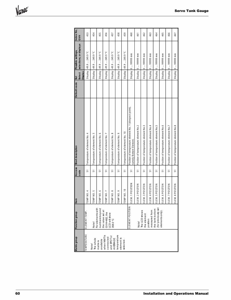
Servo Tank Gauge
60 Installation and Operations Manual
Ma
trix
gro
up
Fun
ctio
ng
rou
pIte
mA
cc
ess
co
de
Sho
rtd
esc
riptio
nD
efa
ult
vau
leSe
tSe
lec
tD
isp
lay
Poss
ible
setti
ng
s,se
lec
tions
,or
dis
pla
ysIn
de
xN
o,
GV
H
TEM
PER
ATU
RE
ELEM
ENT
TEM
P.TE
MP
NO
.451
Tem
pera
ture
ofel
emen
tNo.
4D
ispl
ay-4
9.9
...24
9.9
°C45
3
TEM
PN
O.5
51Te
mpe
ratu
reof
elem
entN
o.5
Dis
play
-49.
9...
249.
9°C
454
TEM
PN
O.6
51Te
mpe
ratu
reof
elem
entN
o.6
Dis
play
-49.
9...
249.
9°C
455
TEM
PN
O.7
51Te
mpe
ratu
reof
elem
entN
o.7
Dis
play
-49.
9...
249.
9°C
456
TEM
PN
O.8
51Te
mpe
ratu
reof
elem
entN
o.8
Dis
play
-49.
9...
249.
9°C
457
TEM
PN
O.9
51Te
mpe
ratu
reof
elem
entN
o.9
Dis
play
-49.
9...
249.
9°C
458
TEM
PN
O.1
051
Tem
pera
ture
ofel
emen
tNo.
10D
ispl
ay-4
9.9
...24
9.9
°C45
9
ELEM
ENT
POSI
TIO
NEL
EM.1
POSI
TIO
N51
Posi
tion
ofte
mpe
ratu
reel
emen
tNo.
1(d
eepe
stpo
int),
nam
ely
Bot
tom
Elem
ent.
Dis
play
0...
9999
9m
m46
0
ELEM
.2PO
SITO
N51
Posi
tion
ofte
mpe
ratu
reel
emen
tNo.
2D
ispl
ay0
...99
999
mm
461
ELEM
.3PO
SITO
N51
Posi
tion
ofte
mpe
ratu
reel
emen
tNo.
3D
ispl
ay0
...99
999
mm
462
ELEM
.4PO
SITO
N51
Posi
tion
ofte
mpe
ratu
reel
emen
tNo.
4D
ispl
ay0
...99
999
mm
463
ELEM
.5PO
SITO
N51
Posi
tion
ofte
mpe
ratu
reel
emen
tNo.
5D
ispl
ay0
...99
999
mm
464
ELEM
.6PO
SITO
N51
Posi
tion
ofte
mpe
ratu
reel
emen
tNo.
6D
ispl
ay0
...99
999
mm
465
ELEM
.7PO
SITO
N51
Posi
tion
ofte
mpe
ratu
reel
emen
tNo.
7D
ispl
ay0
...99
999
mm
466
ELEM
.8PO
SITO
N51
Posi
tion
ofte
mpe
ratu
reel
emen
tNo.
8D
ispl
ay0
...99
999
mm
467
No
te!
Fore
lem
en
tsw
ithn
um
be
rsb
eyo
nd
the
valu
ese
ta
tG
VH
=48
2,th
eLC
Dw
illsh
ow
358.
0°C
No
te!
The
LCD
sho
ws
the
ele
me
nt
po
sitio
nm
ea
sure
dfr
om
the
tan
kb
ott
om
(fo
rpre
vio
usly
set
ele
me
nts
on
ly).
No
te!
The
wh
ole
ma
trix
isa
vaila
ble
wh
en
NM
Tis
co
nn
ec
ted
an
dSP
OT
or
AV
ERA
GE
tem
pe
ratu
ree
lem
en
tis
sele
cte
d.
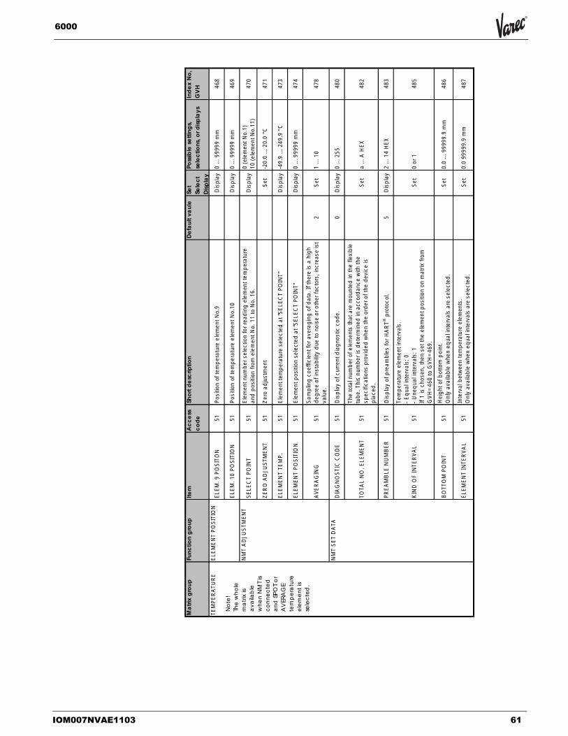
IOM007NVAE1103 61
6000
Sakura Endress
Ma
trix
gro
up
Fun
ctio
ng
rou
pIte
mA
cc
ess
co
de
Sho
rtd
esc
riptio
nD
efa
ult
vau
leSe
tSe
lec
tD
isp
lay
Poss
ible
setti
ng
s,se
lec
tions
,or
dis
pla
ysIn
de
xN
o,
GV
H
TEM
PER
ATU
RE
ELEM
ENT
POSI
TIO
NEL
EM.9
POSI
TON
51Po
sitio
nof
tem
pera
ture
elem
entN
o.9
Dis
play
0...
9999
9m
m46
8
ELEM
.10
POSI
TIO
N51
Posi
tion
ofte
mpe
ratu
reel
emen
tNo.
10D
ispl
ay0
...99
999
mm
469
NM
TA
DJU
STM
ENT
SELE
CT
POIN
T51
Elem
entn
umbe
rsel
ectio
nfo
rrea
ding
elem
entt
empe
ratu
rean
dpo
sitio
nfro
mel
emen
tNo.
11to
No.
16.
Dis
play
0(e
lem
entN
o.1)
10(e
lem
entN
o.11
)47
0
ZER
OAD
JUST
MEN
T51
Zero
adju
stm
ent
Set
-20.
0...
20.0
°C47
1
ELEM
ENT
TEM
P.51
Elem
entt
empe
ratu
rese
lect
edat
"SEL
ECT
POIN
T"D
ispl
ay-4
9.9
...24
9.9
°C47
3
ELEM
ENT
POSI
TIO
N51
Elem
entp
ositi
onse
lect
edat
"SEL
ECT
POIN
T"D
ispl
ay0
...99
999
mm
474
AVE
RA
GIN
G51
Sam
plin
gco
effic
ient
fora
vera
ging
ofda
ta.I
fthe
reis
ahi
ghde
gree
ofin
stab
ility
due
tono
ise
orot
herf
acto
rs,i
ncre
ase
ist
valu
e.2
Set
1...
1047
8
NM
TSE
TD
ATA
DIA
GN
OST
ICC
OD
E51
Dis
play
ofcu
rrent
diag
nost
icco
de.
0D
ispl
ay0
...25
548
0
TOTA
LN
O.E
LEM
ENT
51
The
tota
lnum
bero
fele
men
tsth
atar
em
ount
edin
the
flexi
ble
tube
.Thi
snu
mbe
ris
dete
rmin
edin
acco
rdan
cew
ithth
esp
ecifi
catio
nspr
ovid
edw
hen
the
orde
roft
hede
vice
ispl
aced
.
Set
a...
AH
EX48
2
PREA
MB
LEN
UM
BER
51D
ispl
ayof
prea
mbl
esfo
rHA
RT®
prot
ocol
.5
Dis
play
2...
14H
EX48
3
KIN
DO
FIN
TER
VAL
51
Tem
pera
ture
elem
enti
nter
vals
.-E
qual
inte
rval
s:0
-Une
qual
inte
rval
s:1
If1
isch
osen
,the
nse
tthe
elem
entp
ositi
onon
mat
rixfro
mG
VH=4
60to
GVH
=469
.
Set
0or
148
5
BO
TTO
MPO
INT
51H
eigh
tofb
otto
mpo
int.
Onl
yav
aila
ble
whe
neq
uali
nter
vals
are
sele
cted
.Se
t0.
0...
9999
9.9
mm
486
ELEM
ENT
INTE
RVA
L51
Inte
rval
betw
een
tem
pera
ture
elem
ents
.O
nly
avai
labl
ew
hen
equa
lint
erva
lsar
ese
lect
ed.
Set
0.0
9999
9.9
mm
487
No
te!
The
wh
ole
ma
trix
isa
vaila
ble
wh
en
NM
Tis
co
nn
ec
ted
an
dSP
OT
or
AV
ERA
GE
tem
pe
ratu
ree
lem
en
tis
sele
cte
d.

Servo Tank Gauge
62 Installation and Operations Manual
Sakura Endress
Ma
trix
gro
up
Fun
ctio
ng
rou
pIte
mA
cc
ess
co
de
Sho
rtd
esc
riptio
nD
efa
ult
vau
leSe
tSe
lec
tD
isp
lay
Poss
ible
sett
ing
s,se
lec
tion
s,o
rd
isp
lays
Ind
ex
No
,G
VH
TEM
PER
ATU
RE
NM
TSE
TD
ATA
TEM
.AT
SHO
RT
ELE.
51
Tem
pera
ture
indi
catio
nw
hen
elem
enti
ssh
orte
d.Th
isva
lue
isse
ntto
the
Pros
ervo
only
whe
nth
eer
roro
utpu
tis
"ON
"at
GVH
=492
.Whe
nth
eer
roro
utpu
tis
"OFF
",th
eav
erag
ete
mpe
ratu
reis
sent
toth
ePr
oser
vo.
-49.
5°C
Set
488
TEM
.AT
OPE
NEL
E.51
Tem
pera
ture
indi
catio
nw
hen
elem
enti
sop
ened
.Thi
sva
lue
isse
ntto
the
Pros
ervo
only
whe
nth
eer
roro
utpu
tis
"ON
"at
GVH
=492
.Whe
nth
eer
roro
utpu
tis
"OFF
",th
eav
erag
ete
mpe
ratu
reis
sent
toth
ePr
oser
vo.
359.
0°C
Set
489
NM
TD
EVIC
ED
ATA
INST
RU
MEN
TC
OD
E51
Dis
play
ofth
eha
rdw
are
unit
num
ber
Dis
play
490
LAST
DIA
GN
OST
IC51
Dis
play
ofth
ela
ster
rorm
essa
ge.I
fthe
rew
asno
erro
r,th
enth
eLC
Dw
illbe
blan
k.D
ispl
ay49
1
OU
TPU
TAT
ERR
OR
51Se
lect
ion
ofou
tput
and
indi
catio
nin
case
ofsh
ortc
ircui
tor
open
circ
uite
lem
ents
atG
VH=4
88or
498
1Sd
elec
t0:
OFF
1:O
N49
2
CU
SOD
YTR
AN
SFER
51C
usto
dytra
nsfe
rmod
e.If
this
mod
eis
switc
hed
on,t
hen
the
LCD
will
show
on.
OFF
Sdel
ect
OFF
ON
493
POLL
ING
AD
DR
ESS
51
Ass
ignm
ento
fan
addr
ess
toPr
othe
rmo
NM
T535
/6/8
whe
nth
isan
dot
herH
AR
T®de
vice
sar
em
ulti-
drop
ped
onth
eH
AR
T®co
mm
unic
atio
nlin
e.Po
lling
addr
ess
2is
fixed
byPr
oser
vofir
mw
are.
2Se
t1
...F
(Tot
al16
addr
ess
can
bese
t.)49
4
MA
NU
FAC
TUR
ERID
51Id
entif
icat
ion
num
bero
fthe
man
ufac
ture
r(17
for
Endr
ess+
Hau
ser).
17D
ispl
ay49
5
SOFT
WA
RE
VERS
ION
51So
ftwar
eve
rsio
nof
the
Prot
herm
oN
MT5
35/6
/8.
5.0
Dis
play
4.0
orhi
gher
496
HAR
DW
ARE
VER
SIO
N51
Har
dwar
eve
rsio
nof
the
Prot
herm
oN
MT5
35/6
/8.
1.4
Dis
play
1.4
orhi
gher
497
DEV
ICE
TYPE
CO
DE
51D
ispl
ayof
the
devi
cety
peco
de(1
81fo
rthe
Prot
herm
oN
MT5
35/6
/8).
181
Dis
play
499
No
te!
The
wh
ole
ma
trix
isa
vaila
ble
wh
en
NM
Tis
co
nn
ec
ted
an
dSP
OT
or
AV
ERA
GE
tem
pe
ratu
ree
lem
en
tis
sele
cte
d.

IOM007NVAE1103 63
6000
Ma
trix
gro
up
Fun
ctio
ng
rou
pIte
mA
cc
ess
co
de
Sho
rtd
esc
riptio
nD
efa
ult
vau
leSe
tSe
lec
tD
isp
lay
Poss
ible
setti
ng
s,se
lec
tions
,or
dis
pla
ysIn
de
xN
o,
GV
H
HA
RT
DEV
ICE
(1)(
2)M
EASU
RED
VALU
E(P
rimar
yVa
riabl
eD
ata)
0D
ispl
ayof
prim
ary
varia
ble
ofth
eH
AR
Tde
vice
(e.g
.pre
ssur
ese
nsor
)con
nect
edto
the
Pros
ervo
with
mea
surin
gun
it.D
ispl
ay54
0/6
40
(Sec
onda
ryVa
riabl
eD
ata)
0D
ispl
ayof
seco
ndH
ART
devi
ceco
nnec
tion.
IfO
Nis
sele
cted
,the
HAR
Tde
vice
mat
rixw
illbe
avai
labl
e.54
1/6
41
HAR
TD
EVIC
E(1
)(2)
51
Sele
ctio
nof
HA
RT
devi
ceco
nnec
tion.
-ON
-LIQ
UID
TEM
P.-G
ASTE
MPE
RA
TURE
(forH
ART
devi
ce(1
)onl
y-O
FFW
hen
LIQ
UID
TEM
P.Is
sele
cted
,mea
sure
dte
mpe
ratu
reda
tais
refle
ctin
gto
mat
rixpo
sitio
nG
VH=0
10.
Whe
nG
AS
TEM
PER
ATU
RE
isse
lect
ed,m
easu
red
data
isre
flect
ing
tom
atrix
posi
tion
GVH
=013
OFF
Sele
ct
OFF
LIQ
UID
TEM
P.G
ASTE
MPE
RA
TURE
ON
549
/649
P.V.
SETT
ING
P.V.
RAN
GE
UN
IT51
Setti
ngof
rang
eun
itfo
rprim
ary
varia
ble
inH
ART
com
man
dco
de.
Set
550
/650
P.V.
UPP
ERR
ANG
E51
Setti
ngof
uppe
rran
geof
prim
ary
varia
ble.
Set
551
/651
P.V.
LOW
ERR
ANG
E51
Setti
ngof
low
erra
nge
ofpr
imar
yva
riabl
e.Se
t55
2/6
52
DAM
PVA
LUE
51Se
tting
ofda
mpi
ngva
lue
forp
rimar
yva
riabl
e.Se
t55
3/6
53
SEN
SOR
SPEC
IFIC
SEN
SOR
SER
IAL
NO
.D
ispl
ayof
seria
lnum
bero
fthe
HA
RT
devi
ce.
Dis
play
560
/660
UPP
ERSE
NSO
RLI
MIT
0D
ispl
ayof
uppe
rlim
itof
the
HA
RT
devi
ce.
Dis
play
561
/661
LOW
ERSE
NSO
RLI
MIT
0D
ispl
ayof
low
erlim
itof
the
HA
RT
devi
ce.
Dis
play
562
/662
SELF
DIA
GN
OSI
SER
RO
RC
OD
E(1
)D
ispl
ayof
the
erro
rcod
e(1
)oft
heH
AR
Tde
vice
.D
ispl
ay58
0/6
80
ERR
OR
CO
DE
(2)
Dis
play
ofth
eer
rorc
ode
(2)o
fthe
HA
RT
devi
ce.
Dis
play
581
/681
No
te!
This
ma
trix
ca
nb
eu
sed
for
rea
din
go
fH
AR
TD
EVIC
E(1
)(2
)d
ata
co
nn
ec
ted
toth
eP
rose
rvo
.

Servo Tank Gauge
64 Installation and Operations Manual
Ma
trix
gro
up
Func
tion
gro
up
Item
Ac
ce
ssc
od
eSh
ort
de
scrip
tion
De
fau
ltva
ule
Set
Sele
ct
Dis
pla
y
Poss
ible
sett
ing
s,se
lec
tion
s,o
rd
isp
lays
Ind
ex
No
,G
VH
HA
RT
DEV
ICE
(1)(
2)SE
LFD
IAG
NO
SIS
ERR
OR
CO
DE
(3)
Dis
play
ofth
eer
rorc
ode
(3)o
fthe
HA
RT
devi
ce.
Dis
play
582
/682
ERR
OR
CO
DE
(4)
Dis
play
ofth
eer
rorc
ode
(4)o
fthe
HA
RT
devi
ce.
Dis
play
583
/683
ERR
OR
CO
DE
(5)
Dis
play
ofth
eer
rorc
ode
(5)o
fthe
HA
RT
devi
ce.
Dis
play
584
/684
DEV
ICE
DAT
A
POLL
ING
AD
DR
ESS
Dis
play
ofth
epo
lling
addr
ess
ofth
eH
AR
Tde
vice
tobe
conn
ecte
dto
the
Pros
ervo
.By
the
Pros
ervo
firm
war
esi
de,
polli
ngad
dres
sis
fixed
asfo
llow
s.Po
lling
addr
ess
4:H
ART
DEV
ICE
(1)
Polli
ngad
dres
s5:
HA
RTD
EVIC
E(2
)
Dis
play
591
/691
MA
NU
FAC
TUR
ERID
Dis
play
ofth
em
anuf
actu
rer's
IDof
the
HA
RT
devi
ce.
Dis
play
592
/692
DEV
ICE
TYPE
CO
DE
Dis
play
ofth
ede
vice
type
code
ofth
eH
ART
devi
ce.
Dis
play
593
/693
PREA
MBL
ESSe
tting
ofth
epr
eam
ble
num
ber
Dis
play
594
/694
SOFT
WA
REVE
RSI
ON
Dis
play
ofth
eso
ftwar
eve
rsio
nof
the
HA
RT
devi
ce.
Dis
play
595
/695
HA
RDW
ARE
VER
SIO
ND
ispl
ayof
the
hard
war
eve
rsio
nof
the
HA
RTde
vice
.D
ispl
ay59
6/6
96
DEV
ICE
IDD
ispl
ayof
the
HA
RT
devi
ceIC
conn
ecte
dto
the
Pros
ervo
.D
ispl
ay59
7/6
97
No
te!
This
ma
trix
ca
nb
eu
sed
for
rea
din
go
fH
AR
TD
EVIC
E(1
)(2
)d
ata
co
nn
ec
ted
toth
eP
rose
rvo
.

IOM007NVAE1103 65
6000
Sakura Endress
Mat
rixgr
oup
Func
tion
grou
pIte
mA
cces
sco
deSh
ortd
escr
iptio
nD
efau
ltva
ule
Set
Sele
ctD
ispl
ay
Poss
ible
setti
ngs,
sele
ctio
ns,o
rdis
play
sIn
dex
No,
GVH
ADJ.
SEN
SOR
HA
RTLI
NE
NM
T77
7
Ass
ignm
ento
fPro
ther
mo
NM
T535
/6/7
with
ISH
ART
orN
on-IS
HA
RTco
nnec
tion.
-TER
MIN
ALPO
RT
B:N
on-IS
HA
RT
conn
ectio
n-T
ERM
INAL
POR
TA
:IS
HAR
Tco
nnec
tion
TER
MIN
ALPO
RT
BSe
tTE
RM
INA
LPO
RT
BTE
RM
INA
LPO
RT
A77
0
HAR
TD
EVIC
E(1
)77
7
Ass
ignm
ento
fthe
HAR
TD
EVIC
E(1
)with
ISH
AR
T®or
Non
-ISH
ART
®co
nnec
tion.
-TER
MIN
ALPO
RT
B:N
on-IS
HA
RT®
conn
ectio
n-T
ERM
INAL
POR
TA
:IS
HAR
T®co
nnec
tion
TER
MIN
ALPO
RT
BSe
tTE
RM
INA
LPO
RT
BTE
RM
INA
LPO
RT
A77
1
HAR
TD
EVIC
E(2
)77
7
Ass
ignm
ento
fthe
HAR
TD
EVIC
E(2
)with
ISH
AR
T®or
Non
-ISH
ART
®co
nnec
tion.
-TER
MIN
ALPO
RT
B:N
on-IS
HA
RT®
conn
ectio
n-T
ERM
INAL
POR
TA
:IS
HAR
T®co
nnec
tion
TER
MIN
ALPO
RT
BSe
tTE
RM
INA
LPO
RT
BTE
RM
INA
LPO
RT
A77
2
INTE
RFA
CE
AD
JUST
.VO
L.TO
L.FO
RI/F
51Se
tthe
volu
me
tole
ranc
efo
rint
erfa
cem
easu
rem
ent.
0.3
ml
Set
0...
89.0
ml
780
BRE
AK
RATE
51Se
tthe
brea
kra
tefo
rdis
plac
erm
ovem
entu
nder
inte
rface
mea
sure
men
t.15
0Se
t0
...25
578
1
BAL
AN
CE
CO
UN
T51
Sett
heba
lanc
eco
untu
nder
inte
rface
mea
sure
men
t.15
Set
0...
255
782
I/F1
OFF
SET
51Se
tthe
offs
etva
lue
foru
pper
inte
rface
leve
l.0.
0m
mSe
t0
...99
99.9
mm
783
I/F2
OFF
SET
51Se
tthe
offs
etva
lue
form
iddl
ein
terfa
cele
vel.
0.0
mm
Set
0...
9999
.9m
m78
4
No
te!
The
po
rts
sele
ctio
ns
ha
veto
be
do
ne
,w
he
nth
eP
rose
rvo
ha
sEE
xd
[ia]
ce
rtifi
ed
.

Servo Tank Gauge
66 Installation and Operations Manual
10. Setting/installation of the wire drum and displacer10.1 Installation of the Displacer
If the displacer and the gauge of the 6000 STG is delivered separately, the displacer should be installed before mounting of the 6000 STG on the nozzle of the tank takes place. Standard type displacers can easily be installed through the calibration window.
Ø50mm displacers can easily be installed through the calibration window. The weight and the volume of the displacer are marked on it. Please note the data before installing the displacer to the 6000 STG.
Item Procedure Remarks
• Place the 6000 STG on a spacing stand or on two blocks.
• Keep enough free space to lower the measuring wire and to install the dis-placer.
Note!
• Make sure that the 6000 STG is steadily supported.
• Remove the cover of the wire drum housing.
• Take out the stuffing material.
• Remove the support from the housing.
• Take out the wire drum.
• Remove the sticking tape that is fixing the wire drum and the measuring wire.
Caution!
• Handle the wire drum with care. It must neither be damaged nor crimped.
• Turn the wire drum gently by hand clockwise till the ring attached to the mea-suring wire comes out from the opening of the Servo Tank Gauge flange.
• Hook the displacer to the ring.
• Tighten the hook by the wire attached to the dis-placer.
Caution! • Handle the measuring wire
with care. It should never be kinked, twisted, nor bent hard.
• The wire drum turns in intervals of 1/5 revolu-tion.One revolution draws 300 mm displacer mov-ing.The wire drum turns in intervals of 1/5 revolution.
• One revolution draws 300 mm displacer moving.
Holeφ 70 mm
130 mm 130 mm
200
mm
200
mm
Support Wire drum
Allen hexsocket bolt M6
Tighten the hook
Turn the wire drum clockwise
Hook the displacerto the ring

IOM007NVAE1103 67
6000
Item Procedure Remarks
• Mount the 6000 STG on the mounting nozzle of the tank.
• Make sure that the dis-placer does not touch the interior surface of the mounting nozzle.
• Turn the wire drum gently by hand till the ring attached to the measuring wire comes up to the ref-erence line of the calibra-tion window.
• Close the cover of the wire drum housing.
Caution!
• Check that the measuring wire is correctly located in the groove of the wire drum before you turn on the power supply. If the wire runs out of the groove, then replace it carefully..

Servo Tank Gauge
68 Installation and Operations Manual
10.2 Wire drum setting Drum setting is required in following cases:•The wire drum is shipped separately from the housing.•The measuring wire has been cut or replaced.
Item Procedure Remarks
• 1)Remove the measuring wire, and attach the dis-placer to the end of the wire.
• 2)Attach the measuring wire with the pendent dis-placer to the bearing sec-tion. Inside the bearing section is a magnet; mak-ing attachment easy.
• 3)Select “MATRIX OF” GVH=030 in the MORE FUNCTION row of Static Matrix, and then select “SERVICE”.
• 4)Select GVH=372 “DRUM SETTING”
• 5)The default setting, “OFF” will show
• 6)Press the touch control or “+” or “-” key to change “OFF” to “ON”.
• 7) Now that ON is blinking, press the E key.
• 8)Z PHASE CHECK” will appear on the LCD screen.
• 9)The NMS’s motor will run for a while before ON changes back to OFF.
• 10)Set the wire drum attached to the 6000 STG gently by hand so that its arrow points upward.
Note!
• This function requires pre-vious setting of access code 51 on matrix
• G0V3H9 (please refer access code setting in Sect. 10.4)Caution!
• Handle with care not to damage either the measur-ing wire or the wire drum.
Note! • Check carefully that the dis-
placer moves. If the error message Z PHASE NO INPUT appears, then consult Varec Service.
Caution! • Handle with care not to
damage either the measur-ing wire or the wire drum.
Matrix Group SERVICE
SERVICEDRUMSETTING
372
Touch Control
E_ +

IOM007NVAE1103 69
6000
11. Initial SettingsThe following must be set or specified before you attempt to use the 6000 STG:
• Built-in calendar and clock
• Density measurement factors
• Tank height
11.1 Setting the System Date and Time
The Servo Tank Gauge has a built-in calendar and clock that are backed up by an internal power supply source and it is good for 100 hours if power to the Servo Tank Gauge is turned off. The system date and time are set to Japan local date and time before shipment. After installation, adjust them to your local date and time.
Procedure Remarks
• 1)Select GVH=030 ("MATRIX OF") in the "MORE FUNC-TION" (GVH=030) row of Static Matrix, then select "CALI-BRATION".
• 2)"EDITING ENABLED" will appear on the LCD screen.3)Select GVH=193 ("YEAR SETTING").
• 4)The current system year will appear on the LCD screen ("01" for example,, stands for 2001).
• 5)Press the touch control key "+" or "-" until the correct year appears
• 6)The year display should now be blinking. Press the E key to store the year you have set. "EDITING ENABLED" will appear on the LCD screen.
• 7)Select GVH=194 ("MONTH SETTING"), and enter the cor-rect month just as you entered the year above.
• 8)As above, select GVH=195 ("DAY SETTING"), and enter the correct day.
• 9)As above, select G1V9H6 ("HOUR SETTING"), and enter the correct hour.
• 10)As above, select GVH=197 ("MINUTE SETTING"), and enter the correct minute.
• Access code 51 must be selected.

Servo Tank Gauge
70 Installation and Operations Manual
11.2 Initial Settings of Density Measurement
11.3 Setting the Tank Height
Note! Servo Tank Gauge automatically adjusts DIP POINT OFFSET. It is not necessary to adjust DIP POINT OFFSET manually.
Procedure Remarks
• 1)Select function GVH=005 of the Static Matrix to display the "UPPER DENSITY".
• 2)Using the "+" and "-" keys, enter the value expressing the correct density,, then press the "E" key to confirm the entry.
• 3)"EDITING ENABLED" will appear on the LCD screen.
• Access code 51 must be selected.
• If the liquid is layered,, the following steps must also be performed.
• 1) Select GVH=006 of Static Matrix to display the "MIDDLE DENSITY".
• 2) Using the "+" and "-" keys, enter the value expressing the correct density of the middle liquid layer. Press the "E" key to confirm the entry.
• 3) As above, select GVH=007 "LOWER DENSITY" and enter the density value of the lower liquid layer.
• The interfacial measure-ment requires that the cor-rect density of the middle and lower layers be entered. The density value is updated when the Servo Tank Gauge measures the density.
Procedure Remarks
• 1) Select GVH=030 "MATRIX OF" in the row of the "MORE FUNCTION" of Static Matrix, then select "CALIBRATION".
• 2) Select GVH=140 to display the "TANK HEIGHT."
• 3) Using the "+" and "-" keys, enter the value correspond-ing to the tank height, then press the "E" key to confirm the entry.
• 4) "EDITING ENABLED" will appear on the LCD screen..
• Access code 51 must be selected.
• Enter the correct tank height, especially if you cannot conduct an on-site calibration (discussed later).
• If the correct access code is already selected, pressing the "+" or "-" key at this stage will not bring you to the Access Code display; there is no need for you to select the code again.

IOM007NVAE1103 71
6000
12. Initial Weight Calibration
12.1 Displacer Weight Calibration
Weight table calibration must be done after Hall sensor adjustment. Use this procedure for 6000 STG with level measurement function only.
Note! Wind and vibration affect weight table calibration. Not necessary to make Initial Cal-ibration for Startup “All-in-one” (displacer attached) shipments.
Procedure Remarks
1) Enter Access Code 51 or higher, confirm the following data.G3V4H0 Wire Drum Circum.(engraved on wire drum) G3V4H1 Wire Weight Standard SUS =1.40 PTFE=4.55 Hastelloy=2.48 G3V4H2 Displacer Weight (engraved on displacer)
2) Displacer is in calibration window or maintenance chamberSet Operation=STOP Set G3V7H3 Weight Calib. =ONAt ”Low weight set?” enter Yes (+) At ”Displacer Down?” for calibration window, enter NO (-) for mainte-nance chamber, enter Yes (+)
1)Lift displacer until Sa and Sb are stable. Press “E” and (-) keys together.
1)At “Displacer set ok?” enter “E”. At “Displacer on: E & +”, and (+) keys together. Automatic calibration begins ( about 10 minutes).
1)At “2 Table make?” enter No (-). At “Weight Calibration OFF” enter “E”.
Check: Dose G3V7H0=G3V4H2+/-2.0 grams?If yes, calibration is done.If no...-make sure there is no vibration during calibration-repeat Hall sensor adjustment and calibration.
1) Enter Access Code 51 or higher, confirm the following data.G3V4H0 Wire Drum Circum.(engraved on wire drum)G3V4H1 Wire Weight Standard SUS =1.40 PTFE=4.55 Hastelloy=2.48 G3V4H2 Displacer Weight (engraved on displacer) G3V7H9 Zero Adjust Weight=50 x g
1) Displacer is in calibration window or maintenance chamber
Set Operation=STOP Set G3V7H3 Weight Calib.= ON
At”Low weight set?” enter Yes (+)
At “Displacer Down?”...
for calibration window, enter No (-)
for maintenance chamber, enter Yes (+)

Servo Tank Gauge
72 Installation and Operations Manual
12.2 Weight Table The weight table is the weight compensation table for one revolution of the wire drum.
The output from the Hall elements normally shows a sine curve, and the weight table gives the correction of the measured value. Weight table making is carried out in connection with weight calibration.
To make the weight table, the displacer descends 300 mm in intervals of 6 mm. Thus 50 points of the weight correction curve are measured.
The table is checked while the displacer ascends back to the reference position. Fig. 18 shows the principle of the procedure.
After weight table making, the LCD shows "SECOND TABLE SET? Y=+, N=-.", set "N". Then, the weight table is finished.
Note!
• Do not touch wire drum, measuring wire, nor displacer while the displacer descends.
• Do not vibrate the 6000 STG
• Watch the motion of the measuring wire carefully. It must move smoothly at the vertical center of the calibration window.
• Do not turn off the power once the 6000 STG starts to making weight table.\
3) Replace displacer with 50.x g weight, stabilize weight. Press “E” and (-) keys together
1) Replace displacer on wire.
At “Displacer set ok?” enter “E”. AT “Displacer on: E & +”, press “E” and (+) keys together. Automatic calibration begins (about 10 minutes).
1) At “2 Table Make? enter No (-). At “Weight Calibration OFF” enter “E”.
Check: Dose G3V7H2 +/- 2.0 grams? If yes, calibration is done. If no... -make sure there is no vibration during calibration-repeat Hall sensor adjustment and calibration

IOM007NVAE1103 73
6000
13. Operation of the DisplacerThe operation of the displacer for level, bottom level, interface level, and density measurement is possible by touch control.
Procedure Remarks
1)Select function group GVH=020 OPERATION.
2)Select item OPERATION. The LCD shows the command given to the 6000 STG and the displacer position.
• Set access code to 50.
• If editing has pre-viously been enabled by a valid access code, then the request for the code will not appear.
The following commands are available at this position:
LEVELUPSTOPBOTTOM LEVELUPPER INTERF.LEV*MIDD.INTERF.LEV*MIDDLE DENSITY*DENSITY BOTTOM*WATER DIP*REPEATABILITY TEST
*Interface and density measurements are not available unless specifically requested.
•The optional oper-ation commands are available when such options are set.
•Density measure-ment is described in Appendix C.

Servo Tank Gauge
74 Installation and Operations Manual
14. Level Measurement
Procedure Remarks
1) Select GVH=020 "OPERATION" of Static Matrix, and select "MEA-SURED LEVEL" with the "+" and "-" keys.
2) "MEASURED LEVEL" should now be blinking in the LCD screen. Press the "E" key.
3) The displacer will descend down to the surface level and the mea-surement will begin.
4) Press and hold the "E" key for more than 3 seconds to bring up the Home position.
5) In the upper right corner of the screen shows "R-U" or "R-D." As the measurement goes on, this display will change to "T-B," and, when the measurement is over,, the "T-B" will change to "BAL."
6) The number (in mm) to the left of "BAL" is the level height.
• Set access code to 50.
• If editing has previ-ously been enabled by a valid access code, then the request for the code will not appear. ’

IOM007NVAE1103 75
6000
15. On-site Level Calibration
15.1 Before On-Site Level Calibration
The data listed below are important for the operation of the 6000 STG. Please check them before performing on-site calibration.
Note! Make sure that the measuring range of the 6000 STG covers the tank height. Other-wise the measurement cannot be done to the tank bottom.
Basic gauge related data Matrix position
Circumference of the wire drum. Set the value marked on the drum.
340
Measuring wire weight per 10m wire. the value is 1.40 g / 10 m for stainless steel wire 4.55 g/10 m for PTFE coated, and 2.48 g/10 m for Hasteloy C. Consult Varec Service for other wires.
341
Displacer weight. Set the value marked on the displacer. 342Displacer volume. Set the value marked on the displacer. 343Balance volume. Set approximately half the displacer volume. 344Tolerance on the balance volume. Set 1.0 ml for normal applications.
345
Delay time for judging the displacer from balancing position to motion. Set 5 x 100 ms for normal applications.
347
Liquid data Matrix position
Density of upper layer. 005Density of middle layer. 006Density of lower layer. 007
Adjustment data Matrix position
Upper limit of displacer movement, if required. 160Lower limit of displacer movement, if required. 161Overtension value of the measuring wire. Set 350 g for normal applications.
162
Undertension value of the measuring wire. Set 50 g for normal applications.
163
Tank data Matrix position
Elevation level of the manual dipping reference (tank height). 140

Servo Tank Gauge
76 Installation and Operations Manual
15.2 On-Site Level Calibration Procedure
The 6000 STG can measure the absolute distance between tank top and liquid surface by measuring wire and wire drum. A high accuracy of level measurement requires an on-site calibration that sets the gauge to the manual dipping level.
Procedure Remarks
1)Select CALIBRATION in GVH=030 matrix of "MORE FUNCTION."
2)Select function group "CALIBRATION."
3)Select item G1V5H0 "SET LEVEL."
4)Touch once "+" or "-". The Servo Tank Gauge NMS5/7 asks the access code.
5)Set access code 50.
6)Touch "E". The LCD shows "INPUT STORED."
7)Touch "+" or "-" to set or correct the level data,, which are equal to the innage level by manual dipping.
8)Touch "E". The LCD changes to the set value.
• Set access code to 50. The "SET LEVEL" procedure is required after the installation of the Servo Tank Gauge on a tank is com-pleted.
• If editing has pre-viously been enabled by a valid access code, then the request for the code will not appear.
• The "SET LEVEL" procedure will automatically reflect the "DIP POINT OFFSET" procedure. The dip point offset will then be fitted to the input data.
Note!
The data shown in the matrix are updated once when you open the matrix. They will not change automatically with regard to the level change.

IOM007NVAE1103 77
6000
16. Density Measurement(available only when requested)The displacer weight is first measured in relation to the upper and lower layers, then from the data thus obtained, the density is computed.
16.1 Preliminary settings Procedure Remarks
1)Select GVH=030 "MATRIX OF" in the row of "MORE FUNCTION" of Static Matrix, then select "CALIBRATION."
2)Select GVH=143 "DISP. RAISE DENS." of Dynamic Matrix.
3)Set the distance A the displacer will cover in ascending.
4)Select GVH=144 "DISP. SUBM DENS." of Dynamic Matrix.
5)Set the distance the displacer will cover in descending.
• Set access code to 50.
• When the wire drum completes one revolu-tion, the wire is extended for 300 mm. If you set values A and B so that their differ-ence is a multiple of 300, the maximum accuracy of measure-ment is ensured.
• Recommended dis-tance: 150 mm (default)
• Recommended dis-tance: 150 mm (i.e. 150 mm below the liquid surface)
• See Appendix C for the necessary formula.
1)The displacer will stop temporarily at the liquid surface or inter-face.
2)The Servo Tank Gauge NMS5/7 hoists the displacer up to the A level, and measures the displacer weight.
3)The displacer descends down to the B level, and its weight is mea-sured again.
4)Using the weight data thus obtained,, the density is computed.
•The upper layer is either gas or liquid,, depending on whether the tank contains one sort of liquid or two liquids different in nature, which should not be of concern at this stage.
•For the necessary formula, see Appendix C

Servo Tank Gauge
78 Installation and Operations Manual
16.2 Density Measure-ment Procedure Remarks
1)Select GVH=020 "OPERATION", then select "MIDDLE DENSITY" or "DENSITY BOTTOM"
2)The display you selected in step 1 should now be blinking. Press the "E" key.3)The displacer will begin to descend,, stopping once at the liquid sur-face or interface.4)The displacer will ascend up to the recommended 150 mm point (or the point you have set at matrix position GVH=143 "DISP. RAISE DENS.", pausing there for a few seconds.
5)The displacer willdescend down to the point you have set at matrix position GVH=144 "DISP. SUBM. DENS." and stop there.
6)To display the density measured,, select GVH=005 "UPPER DENSITY", GVH=006 "MIDDLE DENSITY", or GVH=007 "DENSITY BOTTOM".

IOM007NVAE1103 79
6000
17. Interface MeasurementUp to 2 interfacial levels can be measured (the upper interface, and the lower interface). Before proceeding the interface measurement, the density of both the upper and the lower layers need to be set correctly (the default is 1 for all layers). The user is responsible for obtaining the necessary data on density.
17.1 Upper Interface Measurement
17.2 Lower Interface Measurement
Measure the lower Interface level as you measured the upper interface level.
Procedure Remarks
1)Select GVH=006 "MIDDLE DENSITY", and enter the density of the liquid above the interface. (Skip this step if the unit you are using has the interface and density measurement functions, and you have already measured the density.)
2)Select GVH=002 "OPERATION",, then select "UPPER INTERF. LEV" with the "+" and "-" keys.
3)"UPPER INTERF. LEV" should now be blinking. Press the "E" key.
4)The displacer will descend down to the upper interface and the measurement will start.
5)Press and hold the "E" key for more than 3 seconds to return to the Home position.
6)"R-U" or "R-D" will appear in the upper right corner of the screen. As the measurement continues, it will change to "T-B" and, once the measurement is over, the "T-B" will change to "BAL."
7)The number (in mm) to the left of "BAL" represents the upper inter-face level.

Servo Tank Gauge
80 Installation and Operations Manual
18. Remote Communication18.1 Serial Pulse Output (V1/022 protocol)
Note!
• The serial pulse communication requires:
• Two-wire twisted pair, screened or non-screened
• max. 120 Ohm
• max. 0.3 mF between cores
• max. 6 km.
Procedure Remarks
1)Select "DEVICE DATA" in GVH=030 matrix of "MORE FUNCTION."
2)Select function group "COMMUNICATION."
3)Select item GVH=285 "ADDRESS."
4)Touch "+" or "-" to set or correct the address of the Servo Tank Gauge on the remote communication line. For Sakura serial pulse communica-tion (V1 or other), enter a value from 0 to 9.
5)Select item GVH=286 "PROTOCOL". 6)Select the type of the Sakura receiver or communication.
The following types are available at this position:
WM550, M/SBBB (also for MIC)MDPV1, ENRAF BPMRACKBUS (RS 485)HART
7)Select item G2V8H7 "COMMU.LINE ADJ.
8)Set "F" for Sakura receivers of the types BBB, MDP, and V1.
Note! •These items require previous setting of access code 51. The" COMMUNICATION" matrix is available when the digital output is ordered.
•"ADDRESS" defines the address of the Servo Tank Gauge NMS5/7 on a serial pulse loop.
•"PROTOCOL" defines the type of the Sakura receiver connected to the Servo Tank Gauge.
Note! •RACKBUS defines the Rackbus RS 485 output.
•"COMMU.LINE ADJ." is needed for tuning in connection with Sakura receivers of the type DX.
•Consult Varec Service for the adjustment of type DX setting.

IOM007NVAE1103 81
6000
18.2 Rackbus RS 485Procedure Remarks
1)Select "DEVICE DATA" in GVH=030 matrix of "MORE FUNCTION."
2)Select function group "COMMUNICATION."
3)Select item GVH=285 "ADDRESS."
4)Touch "+" or "-" to set or correct the address of the Servo Tank Gauge on the remote communication line. For Rackbus RS 485 com-munication, enter a value from 0 to 63. When touch "E",, LCD shows next.
5)Select item GVH=286 "PROTOCOL."
6)Select the type of the Sakura receiver or communication.
The following types are available at this position:
RACKBUS (RS 485)
The termination resistors are on the RS 485 card.
The termination resistor switch is on the RS 485 communication card.
Note! These items require previous setting of access code 51. The "COMMUNICATION" matrix is available when the digital output is ordered.
•"ADDRESS" defines the address of the Servo Tank Gauge NMS5/7 on a Rackbus RS 485.
•For example while NRS or NRM's address is set to 1, this GVH=285 "ADDRESS" must be set to 1.
The other protocol defines the Sakura serial pulse output.
7)Set the resistor switch of the 6000 STG that is farthest from the host to "ON".
Note! The resistor switch is set to OFF on delivery.

Servo Tank Gauge
82 Installation and Operations Manual
19. Settings for Alarm Outputs (4 contacts)An optional function for providing outputs for up to four contacts when the level or the temperature exceeds a specified value can be selected for Servo Tank Gauge. All the parameters are included in screen GVH=240.
19.1 Alarm SettingProcedure Remarks
1) In Static Matrix "MORE FUNCTION," invoke GVH=030 "MATRIX OF" and select "DEVICE DATA."
2) Bring up the Dynamic Matrix GVH=240 "SELECT. RELAY" screen.
3) Since there are four contacts, select "1" and press "E" to display the next Matrix GVH=241 "ASSIGN RELAY."
4) Select an error type to be set from "LEVEL," "LIQUID TEMP.", "CAUTION", "WARNING", and "EMERGENCY ERROR".
• Set the access code at 50.
• For the set error type, see the table below.
• Select "LEVEL" and "LIQUID TEMP." and press "E" to pass to the next screen GVH=242. "EDIT-ING ENABLED" is displayed, and if any error occurs, an alarm is output.
Error Type Contents
LEVEL Set the upper and lower limits of the level using the screens GVH=242 to GVH=247. An alarm is output if either of these values is exceeded.
LIQUID TEMP. Set the upper and lower limits of the temperature using the screens GVH=242 to GVH=247. An alarm is output if either of these values is exceeded.
CAUTION Alarm-level errors are indicated by error message numbers 1 to 10, 14, 16, 17, 19, and 20.
WARNING Warning-level errors are indicated by error message numbers 11, 12, 21, and 22.
EMERGENCY ERROR Critical-level errors are indicated by error message numbers 13, 15, 18, and 23.

IOM007NVAE1103 83
6000
19.2 Setting Level and Temperature Alarms Procedure Remarks
1) When, in screen GVH=241, "LEVEL" or "LIQUID TEMP." is selected, provide the following settings.
2)In GVH=242" RELAY FUNCTION," set either the upper or the lower limit of the alarm. Press "E" to pass to the next screen GVH=243.
3)In GVH=243 "SWITCHING POINT," set an operation value at which an alarm is output. Press "E" to pass to the next screen GVH=244.
4)In GVH=244 "HYSTERESIS," set a hysteresis value (a value used from the start of the relay operation until it returns to the original state) at which the alarm for contact outputs is cancelled. Press "E" to pass to the next screen GVH=245.
5)In GVH=245 "RELAY ON ALARM," select an alarm output method between "NORM. OPENED" and "NORM. CLOSED." Press "E" to pass to the next screen GVH=246.
6)In GVH=246 "ON DELAY TIME," specify, in seconds, a delay until the output of the selected contact alarm begins. Press "E" to pass to the next screen GVH=247.
7)In GVH=247 "OFF DELAY TIME," set a delay until the output of the selected contact alarm is completed.
• The hysteresis value is approximately 100 mmand 2..
• The delay varies according to the appli-cation.

Servo Tank Gauge
84 Installation and Operations Manual
19.3 Alarm History Display
19.4 List of Alarm Messages
Item Procedure Remarks
Matrix Group: Device Data 1) Bring up Static Matrix GVH=034 "ALARM CON-TACT."
Static Matrix 1) Previous static matrix records are sequentially dis-played in "GVH=035", start-ing with the latest record. Up to 100 alarm records can be saved. If the number of records exceeds 100, it is sequentially overwritten starting with the oldest record. The display includes the year, month, day, hour, minute, instrument tempera-ture, and an error sequential number, in this order. For example, 97 3192238 2402 means that an error occurred at 22:38 on March 19, 1997, when the instru-ment temperature was 24 °C and that this is the sec-ond error since Servo Tank Gauge was installed.
• For the details of alarm messages, see 19.4 "List of Alarm Messages."
ALARM CONTACT
MOREFUNCTION
0 3 4
+-E>3s
0 3 5
(Alarm Message)
MOREFUNCTION
Message Cause of Alarm
UPPER LIMIT LEVEL The level has risen above the set alarm operation value.
LOWER LIMIT LEVEL The level has fallen below the set alarm operation value.
UPPER LIMIT TEMP. The temperature has risen above the set alarm operation value.
LOWER LIMIT TEMP. The temperature has fallen below the set alarm operation value.

IOM007NVAE1103 85
6000
20. Settings for Analog 4...20 mA Outputs (2 channels)Servo Tank Gauge has a function for outputting to the receiver a current of 4...20 mA that is proportional to the value of the level or the temperature when it reaches a set value.
20.1 Setting for Output Type Item Procedure Remarks
Matrix Group: Device Data 1)In Static Matrix "MORE FUNCTION," invoke G0V3H0 "MATRIX OF" and select "DEVICE DATA."
Set the access code at 50.
2) Bring up the Dynamic Matrix GVH=250 "ASSIGN OUTPUT 1" screen.
3) Set a type for which 4...20 mA is output (the level or the temperature value). Select either "LEVEL" or "LIQUID TEMP."
4) Press "E" to make a selec-tion and press "E" again to bring up the GVH=251 "ADJUST 4mA" screen. Set a value at which DC4mA is output.
(Example)To set the value at 10.08 m, use the + key to set 10,080 mm.
5) To set a value at which DC20mA is output, specify the setting in step 4 and then press "E" to invoke the GVH=252 "ADJUST 20mA" screen. The remaining part ofthe operation is the same as in step 4.
•To provide set-tings for a sec-ond channel, also use steps 4 and 5.
ANALOGOUT.ADJUS
ASSIGNOUTPUT 1
ADJUST 4mA
‚Q‚T‚O
‚Q‚T‚P
ADJUST 20mA ‚Q‚T‚Q
MOREFUNCTION
‚O‚R‚OMATRIX OF

Servo Tank Gauge
86 Installation and Operations Manual
20.2 Settings for Current Output When Error Occurs
Matrix Group: Device Data 6) Next, set the current out-put when an error occurs. Press "E" to bring up the Matrix GVH=256 "DEVICE AT ALARM screen.
7) On the screen, select a current type from "HOLD," "MAX," and "MIN."
•HOLD: When an error occurs, the current value of the output current is fixed and will not respond to changes in level or temperature.MAX: When an error occurs, a 20 mA current is output instead of the current out-put current.MIN: When an error occurs, a 4 mA current is output instead of the current output current.OFF: No special current is output when an error occurs.
DEVICE AT ALARM
MOREFUNCTION
ANALOGOUT.ADJUS
2 5 6
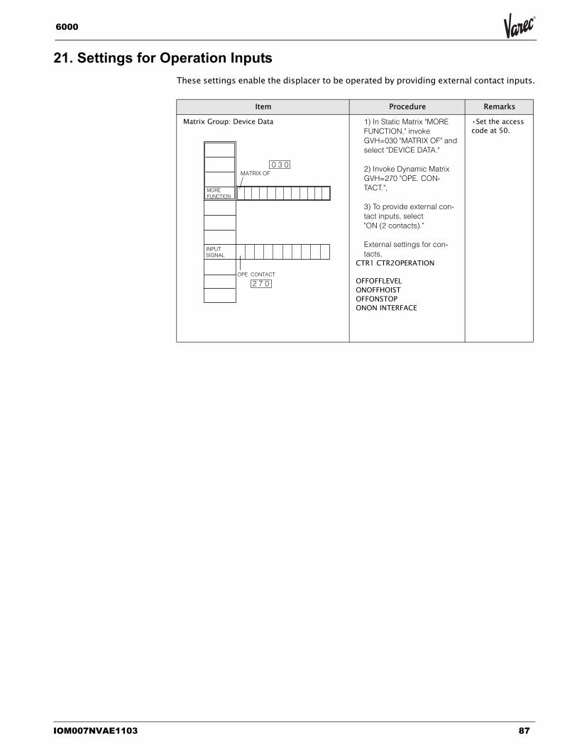
IOM007NVAE1103 87
6000
21. Settings for Operation InputsThese settings enable the displacer to be operated by providing external contact inputs.
Item Procedure Remarks
Matrix Group: Device Data 1) In Static Matrix "MORE FUNCTION," invoke GVH=030 "MATRIX OF" and select "DEVICE DATA."
2) Invoke Dynamic Matrix GVH=270 "OPE. CON-TACT.",
3) To provide external con-tact inputs, select "ON (2 contacts)."
External settings for con-tacts,
CTR1 CTR2OPERATION
OFFOFFLEVELONOFFHOISTOFFONSTOPONON INTERFACE
•Set the access code at 50.
OPE. CONTACT
MOREFUNCTION
INPUTSIGNAL
MATRIX OF
2 7 0
0 3 0
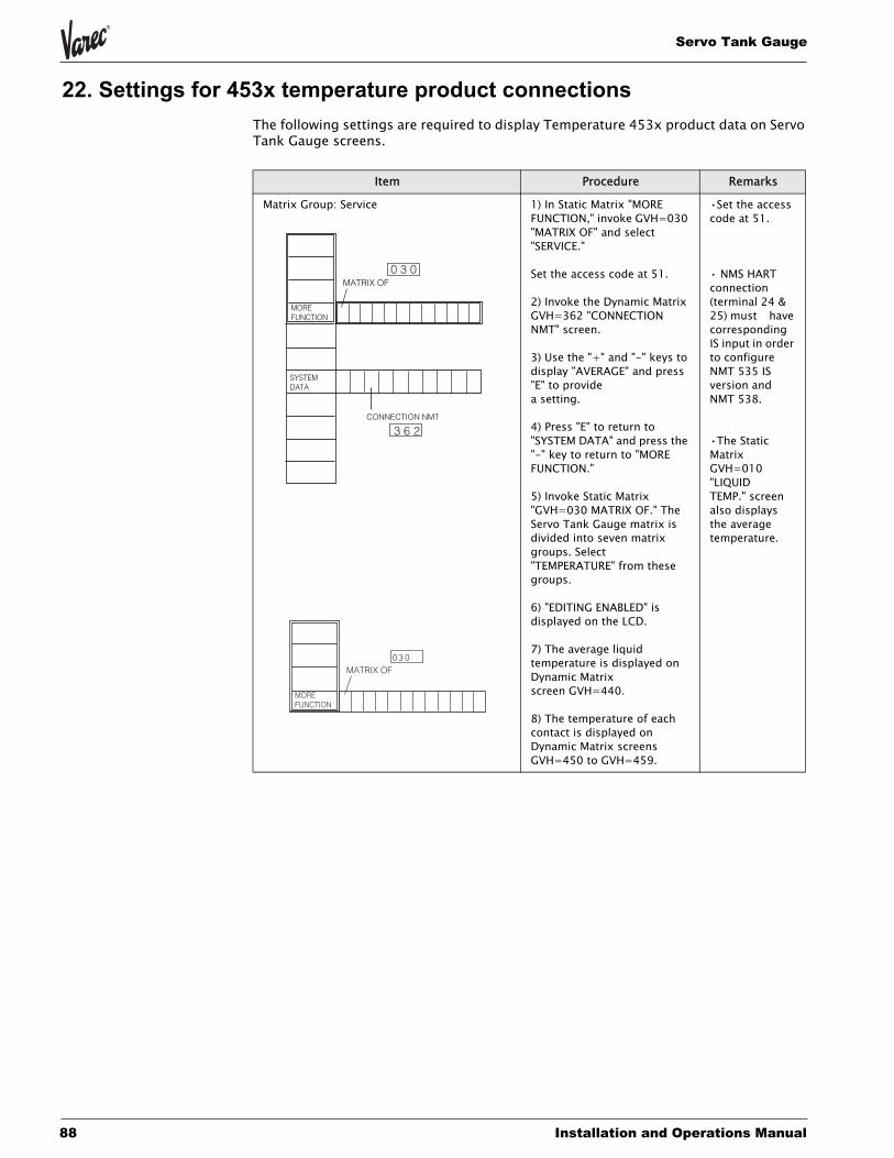
Servo Tank Gauge
88 Installation and Operations Manual
22. Settings for 453x temperature product connectionsThe following settings are required to display Temperature 453x product data on Servo Tank Gauge screens.
Item Procedure Remarks
Matrix Group: Service 1) In Static Matrix "MORE FUNCTION," invoke GVH=030 "MATRIX OF" and select "SERVICE."
Set the access code at 51.
2) Invoke the Dynamic Matrix GVH=362 "CONNECTION NMT" screen.
3) Use the "+" and "-" keys to display "AVERAGE" and press "E" to provide a setting.
4) Press "E" to return to "SYSTEM DATA" and press the "-" key to return to "MORE FUNCTION."
5) Invoke Static Matrix "GVH=030 MATRIX OF." The Servo Tank Gauge matrix is divided into seven matrix groups. Select "TEMPERATURE" from these groups.
6) "EDITING ENABLED" is displayed on the LCD.
7) The average liquid temperature is displayed on Dynamic Matrix screen GVH=440.
8) The temperature of each contact is displayed on Dynamic Matrix screens GVH=450 to GVH=459.
•Set the access code at 51.
• NMS HART connection (terminal 24 & 25) must have corresponding IS input in order to configure NMT 535 IS version and NMT 538.
•The Static Matrix GVH=010 "LIQUID TEMP." screen also displays the average temperature.
CONNECTION NMT
MOREFUNCTION
SYSTEMDATA
MATRIX OF0 3 0
3 6 2
MOREFUNCTION
030MATRIX OF
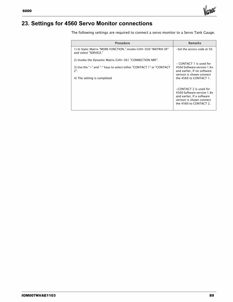
IOM007NVAE1103 89
6000
23. Settings for 4560 Servo Monitor connectionsThe following settings are required to connect a servo monitor to a Servo Tank Gauge.
Procedure Remarks
1) In Static Matrix "MORE FUNCTION," invoke GVH=030 "MATRIX OF" and select "SERVICE."
2) Invoke the Dynamic Matrix GVH=361 "CONNECTION NRF".
3) Use the "+" and "-" keys to select either "CONTACT 1" or "CONTACT 2".
4) The setting is completed
•Set the access code at 50.
• CONTACT 1 is used for 4560 Software version 1.6x and earlier, If no software veriosn is shown connect the 4560 to CONTACT 1.
•CONTACT 2 is used for 4560 Software version 1.8x and earlier, If a software veriosn is shown connect the 4560 to CONTACT 2.
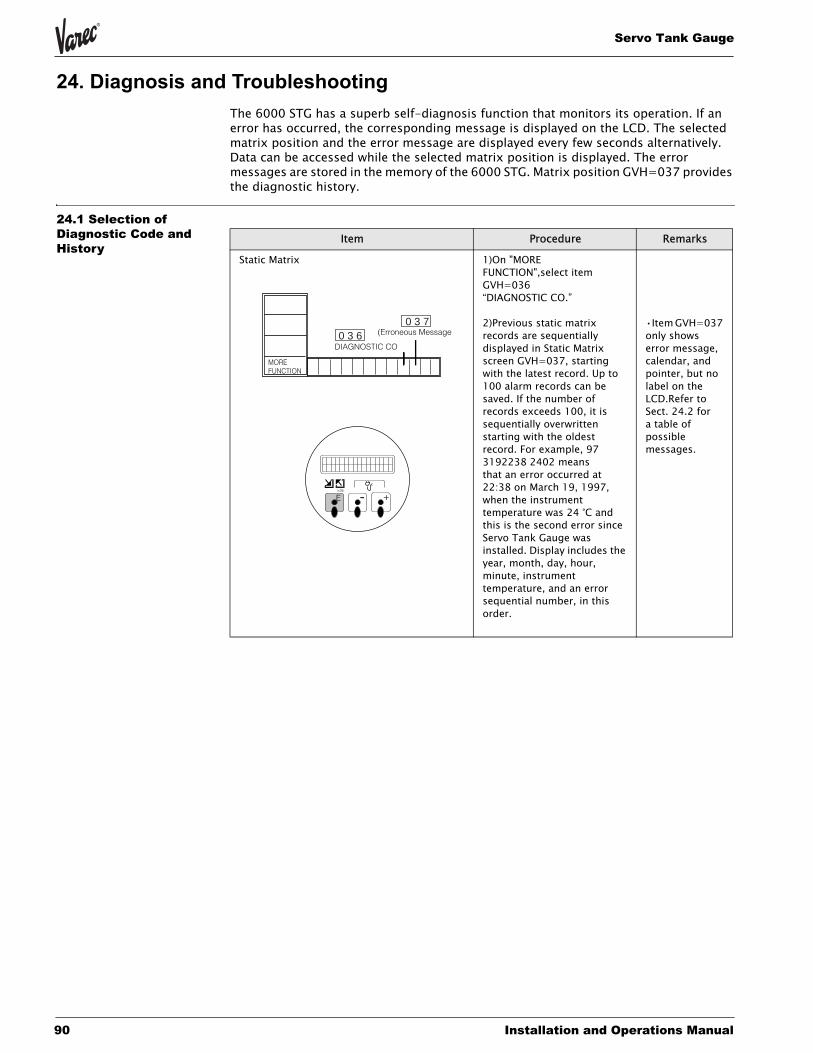
Servo Tank Gauge
90 Installation and Operations Manual
24. Diagnosis and TroubleshootingThe 6000 STG has a superb self-diagnosis function that monitors its operation. If an error has occurred, the corresponding message is displayed on the LCD. The selected matrix position and the error message are displayed every few seconds alternatively. Data can be accessed while the selected matrix position is displayed. The error messages are stored in the memory of the 6000 STG. Matrix position GVH=037 provides the diagnostic history.
24.1 Selection of Diagnostic Code and History
Item Procedure Remarks
Static Matrix 1)On "MORE FUNCTION",select item GVH=036 “DIAGNOSTIC CO.”
2)Previous static matrix records are sequentially displayed in Static Matrix screen GVH=037, starting with the latest record. Up to 100 alarm records can be saved. If the number of records exceeds 100, it is sequentially overwritten starting with the oldest record. For example, 97 3192238 2402 means that an error occurred at 22:38 on March 19, 1997, when the instrument temperature was 24 °C and this is the second error since Servo Tank Gauge was installed. Display includes the year, month, day, hour, minute, instrument temperature, and an error sequential number, in this order.
•Item GVH=037 only shows error message, calendar, and pointer, but no label on the LCD.Refer to Sect. 24.2 for a table of possible messages.
MOREFUNCTION
DIAGNOSTIC CO
(Erroneous Message0 3 7
0 3 6
+-E>3s
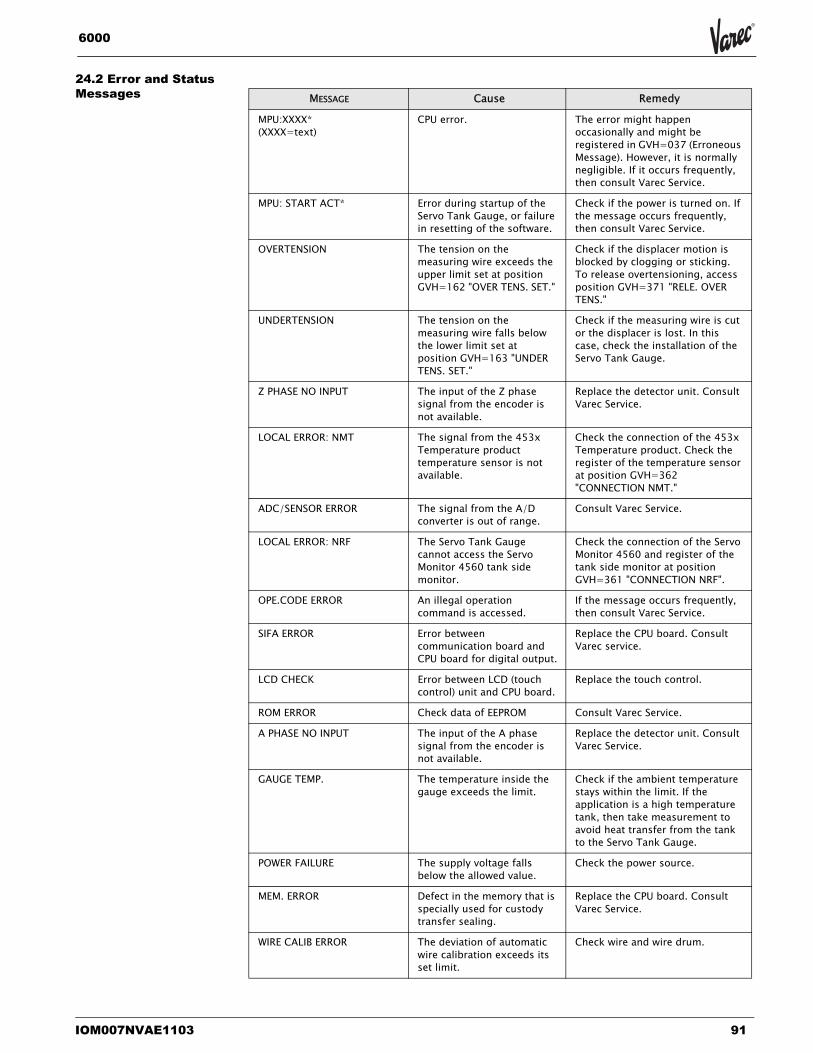
IOM007NVAE1103 91
6000
24.2 Error and Status Messages MESSAGE Cause Remedy
MPU:XXXX* (XXXX=text)
CPU error. The error might happen occasionally and might be registered in GVH=037 (Erroneous Message). However, it is normally negligible. If it occurs frequently, then consult Varec Service.
MPU: START ACT* Error during startup of the Servo Tank Gauge, or failure in resetting of the software.
Check if the power is turned on. If the message occurs frequently, then consult Varec Service.
OVERTENSION The tension on the measuring wire exceeds the upper limit set at position GVH=162 "OVER TENS. SET."
Check if the displacer motion is blocked by clogging or sticking. To release overtensioning, access position GVH=371 "RELE. OVER TENS."
UNDERTENSION The tension on the measuring wire falls below the lower limit set at position GVH=163 "UNDER TENS. SET."
Check if the measuring wire is cut or the displacer is lost. In this case, check the installation of the Servo Tank Gauge.
Z PHASE NO INPUT The input of the Z phase signal from the encoder is not available.
Replace the detector unit. Consult Varec Service.
LOCAL ERROR: NMT The signal from the 453x Temperature product temperature sensor is not available.
Check the connection of the 453x Temperature product. Check the register of the temperature sensor at position GVH=362 "CONNECTION NMT."
ADC/SENSOR ERROR The signal from the A/D converter is out of range.
Consult Varec Service.
LOCAL ERROR: NRF The Servo Tank Gauge cannot access the Servo Monitor 4560 tank side monitor.
Check the connection of the Servo Monitor 4560 and register of the tank side monitor at position GVH=361 "CONNECTION NRF".
OPE.CODE ERROR An illegal operation command is accessed.
If the message occurs frequently, then consult Varec Service.
SIFA ERROR Error between communication board and CPU board for digital output.
Replace the CPU board. Consult Varec service.
LCD CHECK Error between LCD (touch control) unit and CPU board.
Replace the touch control.
ROM ERROR Check data of EEPROM Consult Varec Service.
A PHASE NO INPUT The input of the A phase signal from the encoder is not available.
Replace the detector unit. Consult Varec Service.
GAUGE TEMP. The temperature inside the gauge exceeds the limit.
Check if the ambient temperature stays within the limit. If the application is a high temperature tank, then take measurement to avoid heat transfer from the tank to the Servo Tank Gauge.
POWER FAILURE The supply voltage falls below the allowed value.
Check the power source.
MEM. ERROR Defect in the memory that is specially used for custody transfer sealing.
Replace the CPU board. Consult Varec Service.
WIRE CALIB ERROR The deviation of automatic wire calibration exceeds its set limit.
Check wire and wire drum.
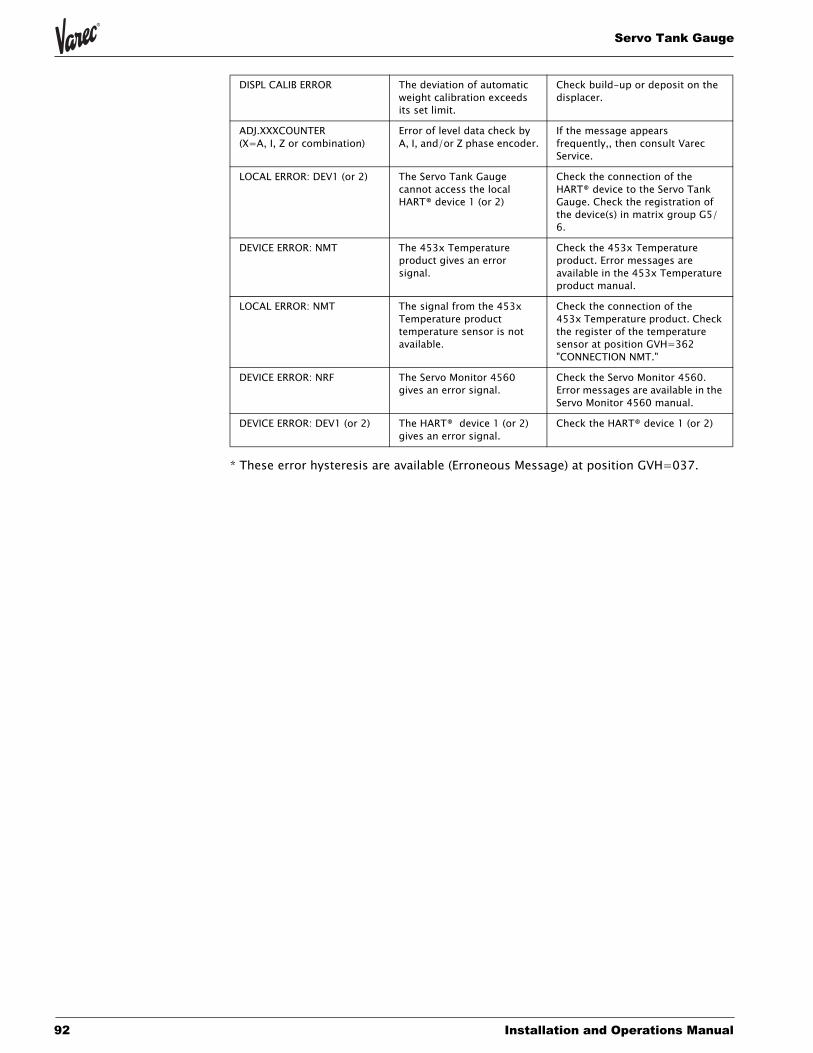
Servo Tank Gauge
92 Installation and Operations Manual
* These error hysteresis are available (Erroneous Message) at position GVH=037.
DISPL CALIB ERROR The deviation of automatic weight calibration exceeds its set limit.
Check build-up or deposit on the displacer.
ADJ.XXXCOUNTER(X=A, I, Z or combination)
Error of level data check by A, I, and/or Z phase encoder.
If the message appears frequently,, then consult Varec Service.
LOCAL ERROR: DEV1 (or 2) The Servo Tank Gauge cannot access the local HART® device 1 (or 2)
Check the connection of the HART® device to the Servo Tank Gauge. Check the registration of the device(s) in matrix group G5/6.
DEVICE ERROR: NMT The 453x Temperature product gives an error signal.
Check the 453x Temperature product. Error messages are available in the 453x Temperature product manual.
LOCAL ERROR: NMT The signal from the 453x Temperature product temperature sensor is not available.
Check the connection of the 453x Temperature product. Check the register of the temperature sensor at position GVH=362 "CONNECTION NMT."
DEVICE ERROR: NRF The Servo Monitor 4560 gives an error signal.
Check the Servo Monitor 4560. Error messages are available in the Servo Monitor 4560 manual.
DEVICE ERROR: DEV1 (or 2) The HART® device 1 (or 2) gives an error signal.
Check the HART® device 1 (or 2)
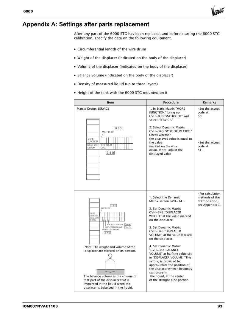
IOM007NVAE1103 93
6000
Appendix A: Settings after parts replacementAfter any part of the 6000 STG has been replaced, and before starting the 6000 STG calibration, specify the data on the following equipment.
• Circumferential length of the wire drum
• Weight of the displacer (indicated on the body of the displacer)
• Volume of the displacer (indicated on the body of the displacer)
• Balance volume (indicated on the body of the displacer)
• Density of measured liquid (up to three layers)
• Height of the tank with the 6000 STG mounted on it
Item Procedure Remarks
Matrix Group: SERVICE 1. In Static Matrix "MORE FUNCTION," bring up GVH=030 "MATIRX OF" and select "SERVICE."
2. Select Dynamic Matrix GVH=340 "WIRE DRUM CIRC." Check whether the displayed value is equal to the value marked on the wire drum. If not, adjust the displayed value
•Set the access code at 50.
•Set the access code at 51..
1. Select the Dynamic Matrix screen GVH=341.
2. Set Dynamic Matrix GVH=342 "DISPLACER WEIGHT" at the value marked on the displacer.
3. Set Dynamic Matrix GVH=343 "DISPLACER VOLUME" at the value marked on the displacer.
4. Set Dynamic Matrix "GVH=344 BALANCE VOLUME" at half the value set in "DISPLACER VOLUME. "This setting is provided to approximate the position of the displacer when it becomes stationary in the liquid, at the center of the straight pipe portion.
•For calculation methods of the draft position, see Appendix C.
WIRE DRUMCIRC.
MEAS. WIRE& DRUM
0 3 0MATRIX OF
MOREFUNCTION
3 4 0
BALANCE VOLUME
DISPLACER VOLUMEDISPLACER WEIGHT
MEAS. WIRE& DRUM
0 3 0MATRIX OF
MOREFUNCTION
3 4 2
3 4 33 4 4
Note: The weight and volume of the displacer are marked on its bottom.
The balance volume is the volume of that part of the displacer that is immersed in the liquid when the displacer is balanced in the liquid.
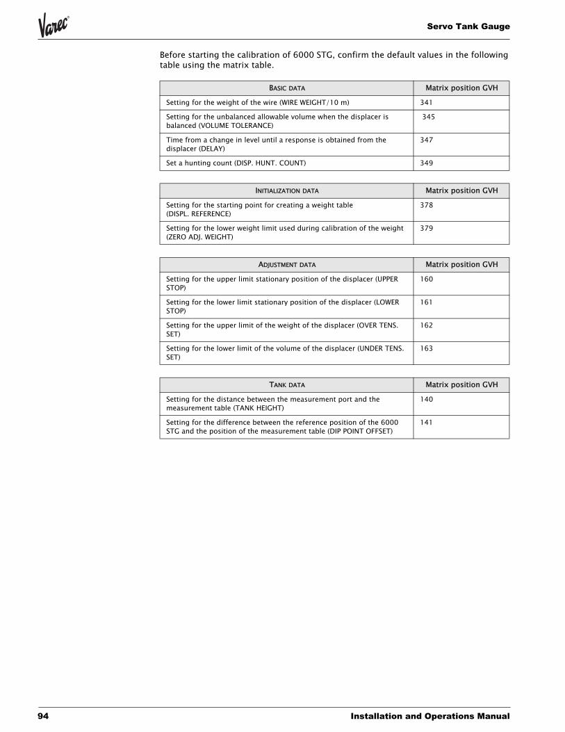
Servo Tank Gauge
94 Installation and Operations Manual
Before starting the calibration of 6000 STG, confirm the default values in the following table using the matrix table.
BASIC DATA Matrix position GVH
Setting for the weight of the wire (WIRE WEIGHT/10 m) 341
Setting for the unbalanced allowable volume when the displacer is balanced (VOLUME TOLERANCE)
345
Time from a change in level until a response is obtained from the displacer (DELAY)
347
Set a hunting count (DISP. HUNT. COUNT) 349
INITIALIZATION DATA Matrix position GVH
Setting for the starting point for creating a weight table (DISPL. REFERENCE)
378
Setting for the lower weight limit used during calibration of the weight (ZERO ADJ. WEIGHT)
379
ADJUSTMENT DATA Matrix position GVH
Setting for the upper limit stationary position of the displacer (UPPER STOP)
160
Setting for the lower limit stationary position of the displacer (LOWER STOP)
161
Setting for the upper limit of the weight of the displacer (OVER TENS. SET)
162
Setting for the lower limit of the volume of the displacer (UNDER TENS. SET)
163
TANK DATA Matrix position GVH
Setting for the distance between the measurement port and the measurement table (TANK HEIGHT)
140
Setting for the difference between the reference position of the 6000 STG and the position of the measurement table (DIP POINT OFFSET)
141
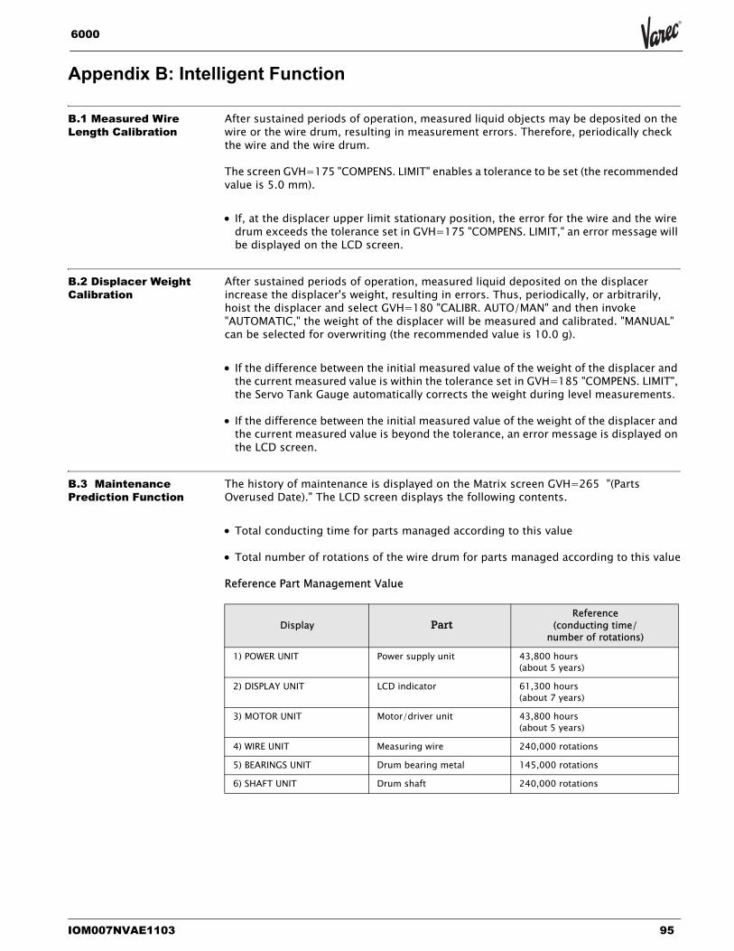
IOM007NVAE1103 95
6000
Appendix B: Intelligent Function
B.1 Measured Wire Length Calibration
After sustained periods of operation, measured liquid objects may be deposited on the wire or the wire drum, resulting in measurement errors. Therefore, periodically check the wire and the wire drum.
The screen GVH=175 "COMPENS. LIMIT" enables a tolerance to be set (the recommended value is 5.0 mm).
• If, at the displacer upper limit stationary position, the error for the wire and the wire drum exceeds the tolerance set in GVH=175 "COMPENS. LIMIT," an error message will be displayed on the LCD screen.
B.2 Displacer Weight Calibration
After sustained periods of operation, measured liquid deposited on the displacer increase the displacer's weight, resulting in errors. Thus, periodically, or arbitrarily, hoist the displacer and select GVH=180 "CALIBR. AUTO/MAN" and then invoke "AUTOMATIC," the weight of the displacer will be measured and calibrated. "MANUAL" can be selected for overwriting (the recommended value is 10.0 g).
• If the difference between the initial measured value of the weight of the displacer and the current measured value is within the tolerance set in GVH=185 "COMPENS. LIMIT", the Servo Tank Gauge automatically corrects the weight during level measurements.
• If the difference between the initial measured value of the weight of the displacer and the current measured value is beyond the tolerance, an error message is displayed on the LCD screen.
B.3 Maintenance Prediction Function
The history of maintenance is displayed on the Matrix screen GVH=265 "(Parts Overused Date)." The LCD screen displays the following contents.
• Total conducting time for parts managed according to this value
• Total number of rotations of the wire drum for parts managed according to this value
Reference Part Management Value
Display PartReference
(conducting time/ number of rotations)
1) POWER UNIT Power supply unit 43,800 hours (about 5 years)
2) DISPLAY UNIT LCD indicator 61,300 hours (about 7 years)
3) MOTOR UNIT Motor/driver unit 43,800 hours(about 5 years)
4) WIRE UNIT Measuring wire 240,000 rotations
5) BEARINGS UNIT Drum bearing metal 145,000 rotations
6) SHAFT UNIT Drum shaft 240,000 rotations
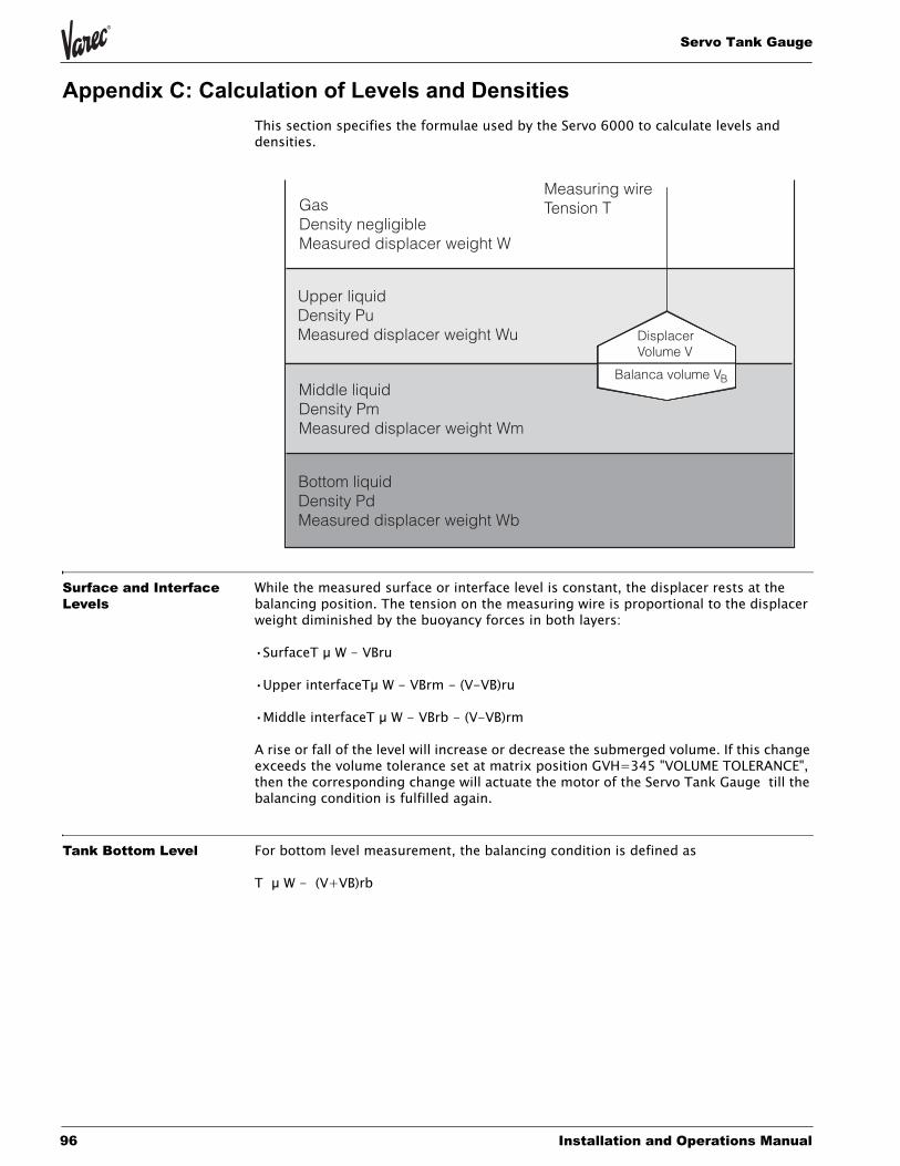
Servo Tank Gauge
96 Installation and Operations Manual
Appendix C: Calculation of Levels and DensitiesThis section specifies the formulae used by the Servo 6000 to calculate levels and densities.
Surface and Interface Levels
While the measured surface or interface level is constant, the displacer rests at the balancing position. The tension on the measuring wire is proportional to the displacer weight diminished by the buoyancy forces in both layers:
•SurfaceT µ W - VBru
•Upper interfaceTµ W - VBrm - (V-VB)ru
•Middle interfaceT µ W - VBrb - (V-VB)rm
A rise or fall of the level will increase or decrease the submerged volume. If this change exceeds the volume tolerance set at matrix position GVH=345 "VOLUME TOLERANCE", then the corresponding change will actuate the motor of the Servo Tank Gauge till the balancing condition is fulfilled again.
Tank Bottom Level For bottom level measurement, the balancing condition is defined as
T µ W - (V+VB)rb
DisplacerVolume V
Balanca volume VB
Measuring wireTension TGas
Density negligibleMeasured displacer weight W
Upper liquidDensity PuMeasured displacer weight Wu
Middle liquidDensity PmMeasured displacer weight Wm
Bottom liquidDensity PdMeasured displacer weight Wb
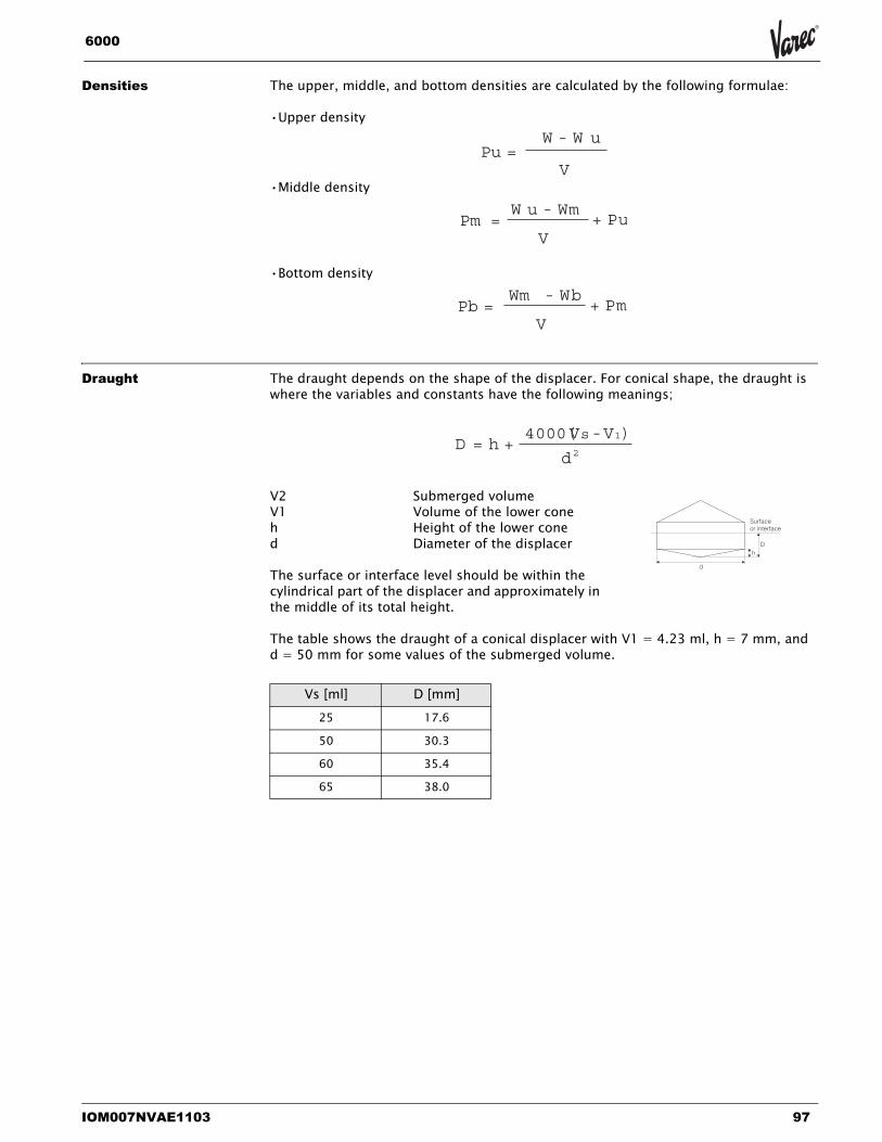
IOM007NVAE1103 97
6000
Densities The upper, middle, and bottom densities are calculated by the following formulae:
•Upper density
•Middle density
•Bottom density
Draught The draught depends on the shape of the displacer. For conical shape, the draught iswhere the variables and constants have the following meanings;
V2 Submerged volumeV1 Volume of the lower coneh Height of the lower coned Diameter of the displacer
The surface or interface level should be within the cylindrical part of the displacer and approximately in the middle of its total height.
The table shows the draught of a conical displacer with V1 = 4.23 ml, h = 7 mm, and d = 50 mm for some values of the submerged volume.
Pu =W - W u
V
Pm =W u - Wm
+ PuV
Pb =Wm - Wb
+ PmV
Vs [ml] D [mm]25 17.6
50 30.3
60 35.4
65 38.0
D =4000( )V -Vs 1
h + d2
Surfaceor interface
D
d
h
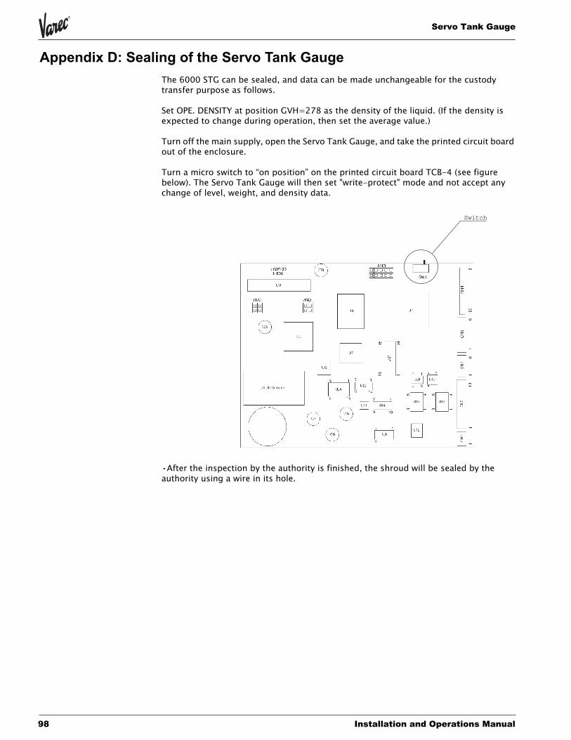
Servo Tank Gauge
98 Installation and Operations Manual
Appendix D: Sealing of the Servo Tank GaugeThe 6000 STG can be sealed, and data can be made unchangeable for the custody transfer purpose as follows.
Set OPE. DENSITY at position GVH=278 as the density of the liquid. (If the density is expected to change during operation, then set the average value.)
Turn off the main supply, open the Servo Tank Gauge, and take the printed circuit board out of the enclosure.
Turn a micro switch to “on position” on the printed circuit board TCB-4 (see figure below). The Servo Tank Gauge will then set "write-protect" mode and not accept any change of level, weight, and density data.
•After the inspection by the authority is finished, the shroud will be sealed by the authority using a wire in its hole.
Switch
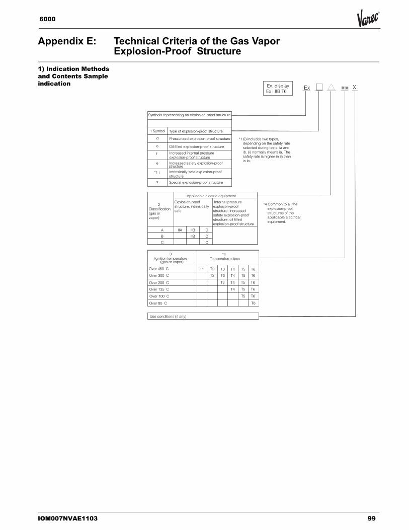
IOM007NVAE1103 99
6000
Appendix E: Technical Criteria of the Gas VaporExplosion-Proof Structure
1) Indication Methods and Contents Sample indication
Ex X....X ....X
Symbols representing an explosion-proof structure
1 Symbol Type of explosion-proof structure
d Pressurized explosion-proof structure
o Oil filled explosion-proof structure
f eIncreased internal pressurexplosion-proof structure
estructurIncreased safety explosion-proof
e
*1 i Intrinsically safe explosion-proofstructure
s Special explosion-proof structure
2Classification(gas orvapor)
Applicable electric equipment
Explosion-proofstructure, intrinsicallysafe
Internal pressureexplosion-proofstructure, increasedsafety explosion-proofstructure, oil filledexplosion-proof structure
A IIA IIB IIC
B IIB IIC
C IIC
3Ignition temperature
(gas or vapor)
*4Temperature class
Over 450 C T1 T2
T2
T3
T3
T3
T4
T4
T4
T4
T5
T5
T5
T5
T5
T6
T6
T6
T6
T6
T6
Over 300 C
Over 200 C
Over 135 C
Over 100 C
Over 85 C
Use conditions (if any)
Ex. displayEx i IIB T6
*1 (i) includes two types,depending on the safety rateselected during tests: ia andib. (i) normally means ia. Thesafety rate is higher in ia thanin ib.
*4 Common to all theexplosion-proofstructures of theapplicable electricalequipment.
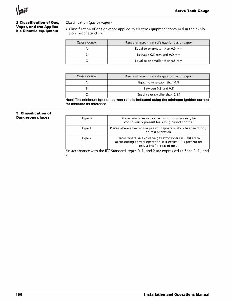
Servo Tank Gauge
100 Installation and Operations Manual
2.Classification of Gas, Vapor, and the Applica-ble Electric equipment
Classification (gas or vapor)
• Classification of gas or vapor applied to electric equipment contained in the explo-sion-proof structure
Note! The minimum ignition current ratio is indicated using the minimum ignition current for methane as reference.
3. Classification of Dangerous places
*In accordance with the IEC Standard, types 0, 1, and 2 are expressed as Zone 0, 1, and 2.
CLASSIFICATION Range of maximum safe gap for gas or vapor
A Equal to or greater than 0.9 mm
B Between 0.5 mm and 0.9 mm
C Equal to or smaller than 0.5 mm
CLASSIFICATION Range of maximum safe gap for gas or vapor
A Equal to or greater than 0.8
B Between 0.5 and 0.8
C Equal to or smaller than 0.45
Type 0 Places where an explosive gas atmosphere may be continuously present for a long period of time.
Type 1 Places where an explosive gas atmosphere is likely to arise during normal operation.
Type 2 Places where an explosive gas atmosphere is unlikely to occur during normal operation. If it occurs, it is present for
only a brief period of time.
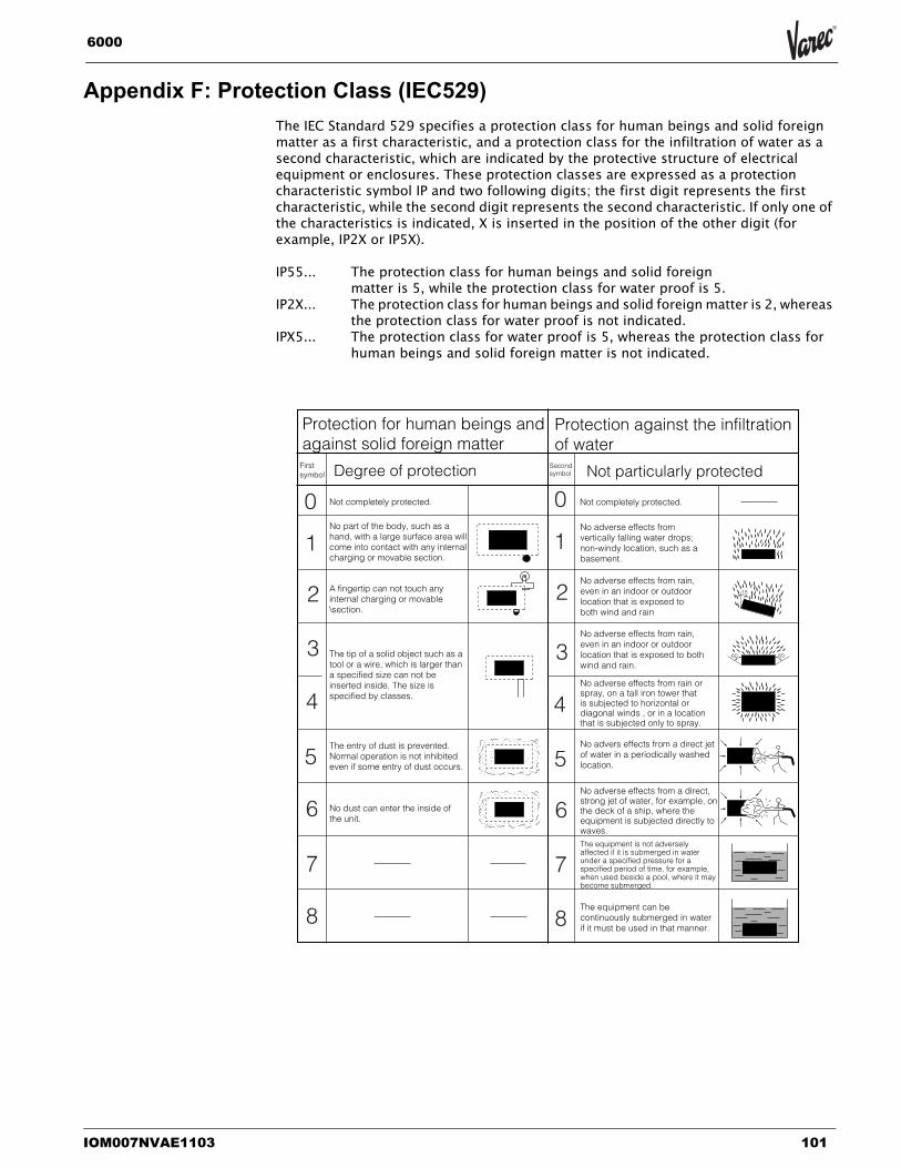
IOM007NVAE1103 101
6000
Appendix F: Protection Class (IEC529)The IEC Standard 529 specifies a protection class for human beings and solid foreign matter as a first characteristic, and a protection class for the infiltration of water as a second characteristic, which are indicated by the protective structure of electrical equipment or enclosures. These protection classes are expressed as a protection characteristic symbol IP and two following digits; the first digit represents the first characteristic, while the second digit represents the second characteristic. If only one of the characteristics is indicated, X is inserted in the position of the other digit (for example, IP2X or IP5X).
IP55... The protection class for human beings and solid foreignmatter is 5, while the protection class for water proof is 5.
IP2X... The protection class for human beings and solid foreign matter is 2, whereas the protection class for water proof is not indicated.
IPX5... The protection class for water proof is 5, whereas the protection class for human beings and solid foreign matter is not indicated.
Protection for human beings and against solid foreign matter
First symbol Degree of protection
Not completely protected.
No part of the body, such as a hand, with a large surface area will come into contact with any internal charging or movable section.
A fingertip can not touch any internal charging or movable \section.
The tip of a solid object such as a tool or a wire, which is larger than a specified size can not beinserted inside. The size is specified by classes.
The entry of dust is prevented. Normal operation is not inhibited even if some entry of dust occurs.
No dust can enter the inside of the unit.
Secondsymbol Not particularly protected
Protection against the infiltration of water
Not completely protected.
No adverse effects from vertically falling water drops; non-windy location, such as a basement.
No adverse effects from rain, even in an indoor or outdoor location that is exposed to both wind and rain
No adverse effects from rain, even in an indoor or outdoor location that is exposed to both wind and rain.
No adverse effects from rain or spray, on a tall iron tower that is subjected to horizontal or diagonal winds , or in a location that is subjected only to spray.
No advers effects from a direct jet of water in a periodically washed location.
No adverse effects from a direct, strong jet of water, for example, onthe deck of a ship, where the equipment is subjected directly to waves.The equipment is not adversely affected if it is submerged in water under a specified pressure for a specified period of time, for example, when used beside a pool, where it may become submerged.
The equipment can be continuously submerged in water if it must be used in that manner.
0
1
2
3
4
5
6
7
8
0
1
2
3
4
5
6
7
8
15
60 60
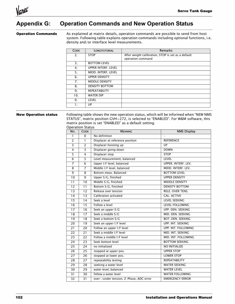
Servo Tank Gauge
102 Installation and Operations Manual
Appendix G: Operation Commands and New Operation StatusOperation Commands As explained at matrix details, operation commands are possible to send from host
system. Following table explains operation commands including optional functions, i.e. density and/or interface level measurements.
New Operation status Following table shows the new operation status, which will be informed when “NEW NMS STATUS”, matrix position GVH=272, is selected to “ENABLED”. For W&M software, this matrix position is set “ENABLED” as a default setting.Operation Status
CODE LONGITUTORIAL Remarks2. STOP After weight calibration, STOP is set as a default
operation command3. BOTTOM LEVEL4. UPPER INTERF. LEVEL5. MIDD. INTERF. LEVEL6. UPPER DENSITY7. MIDDLE DENSITY8. DENSITY BOTTOM9. REPEATABILITY10. WATER DIP0. LEVEL1. UP
NO. CODE MEANING NMS Display1 0 No definition -2 1 Displacer at reference position REFERENCE3 2 Displacer hoisting up UP4 3 Displacer going down DOWN5 4 Displacer stop STOP6 5 Level measurement, balanced LEVEL7 6 Upper I/F level, balanced UPPER. INTERF. LEV.8 7 Middle I/F level, balanced MIDD. INTERF. LEV.9 8 Bottom meas. Balanced BOTTOM LEVEL10 9 Upper S/G, finished UPPER DENSITY11 10 Middle S/G, finished MIDDLE DENSITY12 11 Bottom S/G, finished DENSITY BOTTOM13 12 Release over tension RELE. OVER TENS.14 13 Calibration activated CAL. ACTIVE15 14 Seek a level LEVEL SEEKING16 15 Follow a level LEVEL FOLLOWING17 16 Seek an upper S/G UPP. DEN. SEEKING18 17 Seek a middle S/G MID. DEN. SEEKING19 18 Seek a bottom S/G BOT. DEN. SEEKING20 19 Seek an upper I/F level UPP. INT. SEEKING21 20 Follow an upper I/F level UPP. INT. FOLLOWING22 21 Seek a middle I/F level MID. INT. SEEKING23 22 Follow a middle I/F level MID. INT. FOLLOWING24 23 Seek bottom level BOTTOM SEEKING25 24 no initialized NO INITIALIZE26 25 stopped at upper pos. UPPER STOP27 26 stopped at lower pos. LOWER STOP28 27 repeatability testing REPEATABILITY29 28 seeking a water level WATER SEEKING30 29 water level, balanced WATER LEVEL31 30 follow a water level WATER FOLLOWING32 31 over-/under tension, Z-Phase, ADC error EMERGENCY ERROR
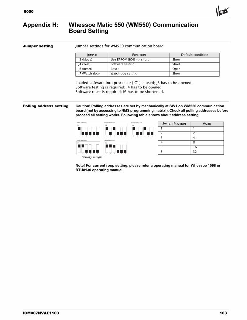
IOM007NVAE1103 103
6000
Appendix H: Whessoe Matic 550 (WM550) Communication Board Setting
Jumper setting Jumper settings for WM550 communication board
Loaded software into processor [IC1] is used; J3 has to be opened.Software testing is required; J4 has to be openedSoftware reset is required; J6 has to be shortened.
Polling address setting Caution! Polling addresses are set by mechanically at SW1 on WM550 communication board (not by accessing to NMS programming matrix!). Check all polling addresses before proceed all setting works. Following table shows about address setting.
Note! For current roop setting, please refer a operating manual for Whessoe 1098 or RTU8130 operating manual.
JUMPER FUNCTION Default conditionJ3 (Mode) Use EPROM [IC4] -> short ShortJ4 (Test) Software testing ShortJ6 (Reset) Reset OpenJ7 (Watch dog) Watch dog setting Short
SWITCH POSITION VALUE
1 12 23 44 85 166 32
ON
1 2 3 4 5 6
Polling address = 1
ON
1 2 3 4 5 6
Polling address = 5
ON
1 2 3 4 5 6
Polling address = 9
ON
1 2 3 4 5 6
Polling address = 3
ON
1 2 3 4 5 6
Polling address = 7
Setting Sample
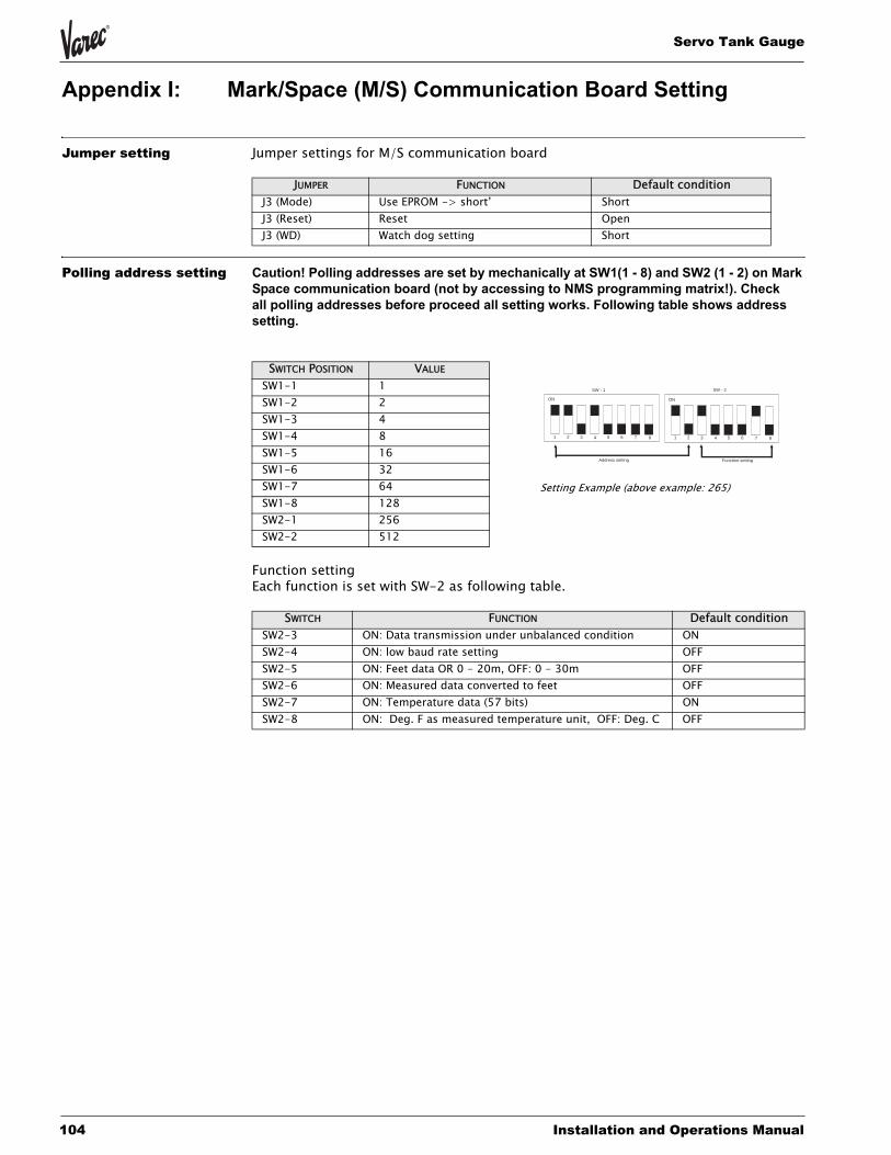
Servo Tank Gauge
104 Installation and Operations Manual
Appendix I: Mark/Space (M/S) Communication Board Setting
Jumper setting Jumper settings for M/S communication board
Polling address setting Caution! Polling addresses are set by mechanically at SW1(1 - 8) and SW2 (1 - 2) on Mark Space communication board (not by accessing to NMS programming matrix!). Check all polling addresses before proceed all setting works. Following table shows address setting.
Function settingEach function is set with SW-2 as following table.
JUMPER FUNCTION Default conditionJ3 (Mode) Use EPROM -> short’ ShortJ3 (Reset) Reset OpenJ3 (WD) Watch dog setting Short
SWITCH POSITION VALUE
SW1-1 1SW1-2 2SW1-3 4SW1-4 8SW1-5 16SW1-6 32SW1-7 64SW1-8 128SW2-1 256SW2-2 512
SWITCH FUNCTION Default conditionSW2-3 ON: Data transmission under unbalanced condition ONSW2-4 ON: low baud rate setting OFFSW2-5 ON: Feet data OR 0 - 20m, OFF: 0 - 30m OFFSW2-6 ON: Measured data converted to feet OFFSW2-7 ON: Temperature data (57 bits) ONSW2-8 ON: Deg. F as measured temperature unit, OFF: Deg. C OFF
ON
1 2 3 4 5 6 7 8
ON
1 2 3 4 5 6 7 8
SW - 1 SW - 2
Address setting Function setting
Setting Example (above example: 265)
IOM007NVAE1103 105
6000
Appendix J: ENRAF Bi Phase Mark Communication Board (COM-3) Setting
Jumper setting COM-3 communication board jumper setting
Communication setting At the matrix position GVH=286, select “V1/ENRAF BPM”.
Polling address setting Polling address setting is possible by accessing to the Servo Tank Gauge matrix, GVH= 285 “ADDRESS”. As polling address, 00 - 99 is possible to use.
Caution! As polling address, A - F is not possible to use!
Others -´Switch S1: Reset switch- Connector J3 : Communication port for debugging
JUMPER FUNCTION Default condition
JP1ROM type setting
1-2 short: 27C40962-3 short: 27C1024
2-3 short
JP2 CPU mode setting1-2 open3-4 short5-6 short
J3 Baud rate setting
1-2 short: 1200 bps1-2 open: 2400 bps
1-2 short
Servo Tank Gauge
106 Installation and Operations Manual
Glossary
AA/D converter A circuit for converting an analogue signal into a digital signal.
Access Code An identification number required to switch the matrix or to change set data
AD Count A number that is a count value represents the digital signal into which the analogue output of the Hall sensor is converted.
Alarm Contact A contact output if it reaches a certain value or meets a certain condition.
Alarm Relay A relay that outputs a contact if it reaches a certain value or meets a certain condition.
Analogue Signal A signal with a temporally continuous value
Anchor WeightA weight used in the guide wire method when the wire hook cannot be welded to the bottom of the tank.
Asymmetric PipeA short pipe that is used for the steel pipe method and that is mounted between the pipe in the tank and the 6000 STG flange to connect them by eccentrically varying its diameter if there is a difference between the pipe and the 6000 STG flange in diameter.
Automatic CompensationAfter a long operation time, deposits are collected on the Weight Data displacer, resulting in a change in the weight of the displacer. This function automatically corrects such change.
BBalance The displacer is balanced and can detect the level or the interface.
Balance Volume The volume (ml) of that part of the displacer, which is submerged in the liquid when it is balanced.
Bearing Unit A section that holds the shaft of the wire drum.
Burr Protrusions that occur when steel pipes are welded, connected, or cut.
CCable A collection of various conductors, which are provided with a cover.
Cable Gland A fixture installed to draw the cable into the terminal box.
Calibration Adjustment or calibration conducted after suspending the operation.Calibration WindowA window for checking the position of the displacer after calibration.
Calibration Window Reference Line
A position or line used as a reference during calibration.
Chamber for Maintenance A T-shaped, short pipe normally mounted for maintenance when the guide wire method and a pressurized tank are used.
Circumference of the Wire Drum
The length of the wire rolled around the wire drum per its rotation.
Common A wire common to plural signals of the same type (potential)
IOM007NVAE1103 107
6000
Communication I C (SIFA) A sensor interface ASIC (a customer IC) developed by Endress+Houser Inc. and having various functions. In 6000 STG, it is used as an integrated circuit to process HART signals.
Concentric Pipe A short pipe that is used for the steel pipe method and that is mounted between the pipe in the tank and the 6000 STG flange to connect them by concentrically varying its diameter if there is a difference between the pipe and the 6000 STG flange in diameter.
Conductivity S/m or an inverse of the resistance rate (j/m). According to the Ohm’s law, I = eE is established wherein (I) is the density of a current, “E” is an electrolytic strength, and e is a conducting rate.
Conical Displacer A displacer shape.
Contact Output A close signal that can be obtained when the relay is activated.
Correction of Balance A condition in which the apparatus is operating very slowly to find a balance point.
Correction value for tank roof distortion
Distortion rate mm/m
Covered Floating Roof Tank A tank with a double roof.
IInsulation Voltage Cables, the covers of which are not damaged if a disturbance of a relatively high voltage
level occurs.
Intelligent Thermometer A thermometer with a microcomputer (Prothermo NMT535/6/7 series thermometers)
Interface Measurement Measuring the depth of the interface between multiple liquids if they are completely separated from each other.
Interface measurement To measure the depth of the interface between multiple liquids that are completely separated from one another.
IP67 (water proof) One of the protection class symbols specified in the JIS Standard.
JJumper Pin A pin used to connect multiple portions in order to create a certain condition.
KKink A condition in which the measuring wire is bent.
LLCD Liquid crystal display
Level The level at which, during level measurements, the displacer is first balanced after being lowered from the reference position.
Level Measurement A condition in which 6000 STG detects the level.
Line Resistance A value input to adjust the resistance of a transmission path used for communication with the exclusive receiver.
Low Weight A set value required during adjustments in order to accurately measure the weight (0.0 g).
Servo Tank Gauge
108 Installation and Operations Manual
Lower Stop The position at which the motor automatically stops when, during measurements, the value of the level, interface, or tank bottom falls below the set value.
MManaged part A part that is periodically changed.
Matrix Position LCD display screens for the static and the dynamic matrixes.
Maximum Correction Value The maximum value of the corrections (the weight of the displacer minus the measured weight) stored after the creation of a weight table.
Measurement Port A port through which the operator inserts a measurement tape to measure the height of the liquid in the tank from its bottom.
Measurement Port Reference Position
A roof-side reference position for measurements.
Measuring Wire A wire used to hoist the displacer.
Measuring Wire Tension Applied tension when the measuring wire is pulled in the direction of the displacer.
Middle Density The density of the intermediate layer of liquid when three types of liquids are separated from one another.
Middle Interface Level The boundary between the intermediate layer of liquid and the lower layer of liquid when three types of liquids are separated from one another.
Minimum Weight Correction Value
The minimum value of the corrections (the weight of the displacer minus the measured weight) stored after the creation of a weight table.
Mounting Nozzle A short pipe disposed at the top of the tank to mount 6000 STG on it.
NNormal Close A contact is closed during normal operation and opened when a set value is reached.
Normal Open A contact is open during normal operation and closed when a set value is reached.
Number of Cable Cores The number of conductor cores accommodated in the covered cable.
OOperation Parameter Set values and data required for operations.
Optical Operating Element A part (a product) that provides an optical signal when touched by a hand.
Output Outputting information or data in 6000 STG.
Over Tension An error in which the weight detected by the detector exceeds the upper limit (set value).
Over Tension A set value used to automatically stop level measurements if a weight larger than a specified value is applied to the measuring wire, in order to prevent the wire from snapping.
PPE Polyethylene (a synthetic resin)
Power Supply Cable An electric wire that supplies power to the power supply section.
Power Unit An electric circuit for generating power required to operate the apparatus.
Programming Matrix A collective name for the static and the dynamic matrixes.
IOM007NVAE1103 109
6000
Pt100 ohm RTD Input Platinum resistance 100 ohm input (spot thermometer input)
PTEE Poly Tetra Fluore Ethylene; commonly referred to as “Teflon”.PVCStands for Poly Vinyl Chloride (a synthetic resin).
RRACK BUS A digital signal used in a rack system commercially available from Varec.
RACK BUS RS485 A digital communication method in which a rack bus is used for field communications.
Receiver Protocol A unique address assigned to 6000 STG in order to communicate with a receiver.
Relay Output A contact signal output when the contact reaches a certain value or meets a certain condition.
Resistance The longer a cable is or the smaller its cross section is, the more difficulty a current has in flowing through the cable. The resistance value represents the degree of such a difficulty.
Resistor input An input to a spot thermometer.
Rod A stick-like object used to adjust the weight of the displacer by somewhat raising the displacer.
SSerial bus (pulse) A signal that enables a large amount of information to be exchanged between multiple
devices through two cables.
Serial Pulse Output A form of signal communication in which data can be updated in both directions, that is, during both transmission and reception. 6000 STG uses an exclusive pulse signal for this form of communication.
Spherical tank A spherical tank that is often used as a high pressure tank.
Stilling Well A steel pipe generally made of iron that is often used for a floating roof tank.
Support A supporting plate for fixing the wire drum to the drum chamber.
SUS316 One of the metallic materials and their grades specified in the JIS Standard (SUS means stainless).
Static Matrix A group of matrixes that display and set basic data for 6000 STG.
TTank Bottom The bottom surface of the tank (bottom plate, zero point)
Tank Roof Distortion The degree of the expansion of the side and the bottom walls of the tank varies depending on whether the tank is empty or filled.
Tank Side Monitor Displays at the starting portion of a companionway the same data on the level and temperature as in the 6000 STG disposed on the tank (Servo Monitor 4560).
Tape-armored Measuring Cable
One type of measuring cable that is used to providemechanical protection against external force.
Terminal Block A relay point used when equipment is connected to the cables and operated.
Terminating Resistance An impedance that is used to terminate the transmission path and that is approximately equal to the characteristic impedance of the line.
Servo Tank Gauge
110 Installation and Operations Manual
Tolerance A tolerance used in measurements. In the 6000 STG matrix, it is considered to be a maximum value that can be output in the presence of an error.Touch ControlThe operator can touch the touch control to change the display and to carry out calibrations and operations.Twisted PairOne or more pairs of twisted cables wrapped by a metallic tape or net, which is further covered with an insulating material.
UUllage Level The distance between the measurement port and the interface.
Unbalanced Status A condition in which the displacer can not detect the level accurately.
Under Tension A set value used to indicated when the weight detected by the detector is abnormally small compared to the weight of the displacer.
Upper Density Density of the top layer of liquid, when three types of liquids are separated from one another.
Upper Interface Level The boundary between the highest layer of liquid and the second highest layer of liquid, when three types of liquids are separated from one another.
Upper Plate A metallic plate mounted immediately below the Servo Tank Gauge flange in the guide-wire method in order to fix the guide wires.
VValve A valve for a pressurized tank, which releases the pressure from the tank during
maintenance.Very Accurate Measurement
A mode used to guarantee higher accuracy in levelMode measurements.
Voltage Drop A phenomenon in which a current flowing through a resistor or an inductor causes the voltage to decrease.
Volume tolerance Changes in weight, from balanced status to the beginning of the movement of the displacer, are based on this volume.
WWeight Calibration Adjustments provided to accurately measure the weight
Weight Correction Curve A curve generated when the correction values (the weight of the displacer minus the measured weight) stored after the creation of a weight table are expressed in a graph.
Weight Table Correction values used to automatically save the (drum correction values)imbalance on the diagonal line on the wire drum.
Wire drum A part that the measuring wire is rolled around to convert the distance over which the displacer has moved into a rotational movement in order to transmit it to the detector.
Wire Hook A fixture that is used for the guide wire method and around which the terminal of the guide wire is wound.
Without Guide System A 6000 STG mounting method that does not use the guide wires or the steel pipes.
ZZ Phase Signal One pulse output from the level encoder every 300mm.

IOM007NVAE1103 111
6000
Servo Tank Gauge
Varec, Inc.5834 Peachtree Corners East, Norcross (Atlanta), GA 30092 USA
Tel: +1 (770) 447-9202 Fax: +1 (770) 662-8939
Your offical representative
www.varec.com
Recommended


