IEEE TRANSACTIONS ON BIOMEDICAL ENGINEERING, VOL. 43, NO. I, JULY 1996 669
A Volume-Conduction Analysis of Magnetic Stimulation of Peripheral Nerves
Jarmo Ruohonen, Paolo Ravazzani, Jan Nilsson, Senior Member, ZEEE, Marcela IPanizza, Ferdinand0 Grandori, *
Abstruct- Magnetic stimulation is a method to study several nervous disorders as well as the intact nervous system in humans. Interest in magnetic stimulation of peripheral nerves has grown rapidly, but difficulties in locating the site of excitation have prevented it from becoming a routine clinical tool. It has been reasoned that the activating function of long and straight nerves is the first spatial derivative of the electric field component parallel to the nerves. Therefore, to predict the site of activation, one has to compute this field feature. We describe here an analytical mathematical model and investigate the influence of volume- conductor shape on the induced field. Predictions of the site of activation are given for typical stimulation coil arrangements and these results are compared with experimental and literature data. Comparisons suggest that the activating function is not simply the spatial gradient of the induced electric field, but that other mechanisms are also involved. The model can be easily utilized in the search for more efficient coil constructions and improved placements with respect to the target nerves.
I. INTRODUCTION
N magnetic stimulation (MS) of the human nervous system, I an induced electric field E' depolarizes locally cell mem- branes and activates corresponding neurons. The activating electric field is generated by a strong time-dependent magnetic field produced by a current circulating in an excitation coil [2]. Here, we concentrate on MS of peripheral nerves, which is used to determine distal conduction velocities of motor and sensory nerves. An abnormal conduction velocity is attributed to many nervous disorders [SI, [14]. In a typical experiment, the median nerve is stimulated at the elbow or wrist and muscle responses are measured with surface electrodes from the thumb. In determination of the conduction velocity it is essential to know the exact locus where the nerves are depolar- ized, so that possible differences between normal subjects and
Manuscript received July 5 , 1994; revised March 12, 1996. This work was supported by the Italian National Research Council (CNR). The work of J. Ruohonen was supported by the Finnish Cultural Foundation, Helsinki, Finland. Asterisk indicates corresponding author.
J. Ruohonen is with Helsinki University Central Hospital, Medical Engi- neering Center, Helsinki FIN-00290 Finland. He is also with the Polytechnic of Milan, System Theory Centre (CNR), Department of Biomedical Engineering, Milan 1-20133 Italy.
P. Ravazzani and G. Tognola are with the Polytechnic of Milan, System Theory Centre (CNR), Department of Biomedical Engineering, Milan 1-20133 Italy.
J. Nilsson and M. Panizza are with the "Salvatore Maugeri" Foundation, IRCCS, Laboratory of Clinical Neurophysiology, Caste1 Goffredo (MN) I- 46042 Italy.
*F. Grandori is with the Polytechnic of Milan, System Theory Centre (CNR), Department of Biomedical Engineering, via Ponzio 34/5 Milan I- 20133 Italy (e-mail: [email protected]).
Publisher Item Identifier S 0018-9294(96)04828-8.
and Gabriella Tognola
patients can be distinguished. Currently, the error in locating the site of excitation is often too large [5] , [131, [141, [20], [261, [30]. This and difficulties in obtaining supramaximal responses have prevented the technique from becoming a routine clinical tool.
Adapting the terminology of Rattay [27], we define the activating function as the depolarizing feature(s) of external electromagnetic fields. With the help of the c1,assical cable theory, in both MS and in electrical stimulation (ES), the activating function of long and straight nerves has been argued to be the negative gradient of the induced electric field along the nerve [3], [24], [27], [:Ill, [32]. In this study, a mathematical method is developed to compute both the induced electric field E' and V . E' and is used to simulate experimental arrangements. A comparison of experimental and simulated data calls into question the adequacy of the cable theory as such to describe magnetic stimulation d peripheral nerves.
Attempts to calculate the induced i? and its gradient have beenmade [4], [ l l ] , [12], [16], [24], [33], butthesie works have been highly simplified, at least for what comes to the shape of the approximating volume conductor. Generally. the volume conductor has been either an unbounded or a semi-infinite medium. In two of these works [12], [33], a homogeneous cylinder was used, but to our knowledge these ,authors have not published any detailed results. We previously described in detail a model based on the use of a stretched homogeneous prolate spheroid to approximate cylincler-li+ke structures [35]. The model is here used to compute both E and its gradient.
We compare an unbounded, a semi-infinite, and a prolate spheroidal volume-conductor shape. It is demonstrated that often the effects from the boundaries are notable, while sometimes the semi-infinite and even the unbounded volume- conductor model give results similar to the spheroid model.
11. MATHEMATICAL MODELING
We apply the so-called reciprocity lheorem (see, e.g., [SI) and connect together two concepts: 1) ,magnetobiology, which is the study of biological effects of rnagnetic fields, and 2) biomagnetism, which is the study of magnetic fiellds from bio- logical activity. These concepts can be sh+own to be reciprocal [ 181: the computation of the induced E in magnetobiology (magnetic Gimulation) is equivalent to that of the magnetic induction B due to known current sources in biomagnetism (magnetoencephalography), and vice versa. Since the biomag-
0018-9294/96$05.00 0 1996 IEEE
670 IEEE TRANSACTIONS ON BIOMEDICAL ENGINEERING, VOL. 43, NO. I, JULY 1996
netic problem has been extensively analyzed [19], [36], it is sensible to apply these results in magnet$ stimulation.
In biomagnetism one often computes B due to an infinitesi- mal current dipole Q , which is a current source-sink pair with an infinitesimal source-sink distance. G i n g the reciprocity theorem, it is straightforward to relate B to the electric field E’ induced by an external loop of wire C carrying a time- dependent quasistatic current I ( t ) [ 181, [28]
+
where E(?”) is a vector normal to a surface bounded by the coil. In (I) , the integration is over an arbitrary surface bounded by the coil. There are no limitations for the coil shape. It is useful to evaluate the integral in two parts
where the subindex “DO” refers to an infinite medium and the subindex “vol” to the modifying effects of conductor boundaries. For a dipole in a homogeneouk volume conductor V, bounded by a surface S, [15]
PO - a’ 471 a3
&(?) = -Q(?’) x - (3)
B. Semi-In$nite Medium
(y < 0) is given by [36] An expression of B’ due to d inside a semi-infinite medium
B’(F‘) = A ( ( d x a’. 5)V’K + K d x y) (7)
where K = a ( a + a y ) and V’K = (2 + a,a-l)a’+ ay. The electric field is then
47rK2
where a’ = F - r” and a = IZI. In (4), a(.”) is the electric potential on the surface S and o is the conductivity of V. A vector normal to S is da. We discuss only simplified geometries where analytical solutions to (4) are available. In more realistic geometries, the expression of Bvol can be evaluated using element methods [19].
Below, we derive analytical expressions of ,!? and EL = a(f . @)/ax for the unbounded, semi-infinite, and prolate spheroidal volume conductors.
-
A. Unbounded Medium
From ( 2 ) and (3) the induced electric field in an unbounded medium is
with
x [KdS(r”) - a’(V’K ’ d s ( F ’ ) ) ] . (8)
Differentiation of 2 . E’ with respect to z gives
2a,a,V’K a,a,a, - ) --a] .dS . (9) K
a,? + a,i -
When the excitation coil is tangential to the surface, i.e., dS = dSjj, expressions in ( 8 ) and (9) reduce to those in (5) and (6) for the unbounded medium.
-
C. Prolate Spheroid
The volume effects B?,,l due to a dipole in the prolate spheroid have been derived by Cuffin and Cohen [lo]. In + a previous paper [35] we give the rectangular components of E in prolate spheroidal coordinates (<, q, c p ) . In [35], it is further shown that when the field point ?is in the central part of the spheroid (x is small when compared to the spheroid’s length), E’, is approximately
E: = E:,,(r3
where c is the semifocal distance. This approximation is accurate in cases of practical interest in magnetic stimulation. Inserting Bvol from [lo], we have
+
Differentiation of i . ,!?,(f) from (5) with respect to z gives the classical activating function in unbounded medium
where u , , ~ , ~ are the components of a’ in the Cartesian coordi- nate system (?,$, 2 ) . From (6), a coil whose axis points to z direction, i.e., dS = d S f , does not induce any E: and should therefore be inadequate for stimulation of nerves in z direction.
The primed variables apply to the elements of the coil; the unprimed to points inside the spheroid. The parameter qa denotes the surface of the spheroid; P,,, and Q,,, are
RUOHONEN et al.: A VOLUME-CONDUCTION ANALYSIS OF MAGNETIC STIMULATlON OF PERIPHERAL NERVES 67 1
- max: 6.84 kV/m2 max: 6.80 kV/m2 4 cm
max: 3.0 kV/m2
-. .- . . - _.
---1
max: 5.6 kV/m max: 3.04 kV/m2
(a) (b) (c)
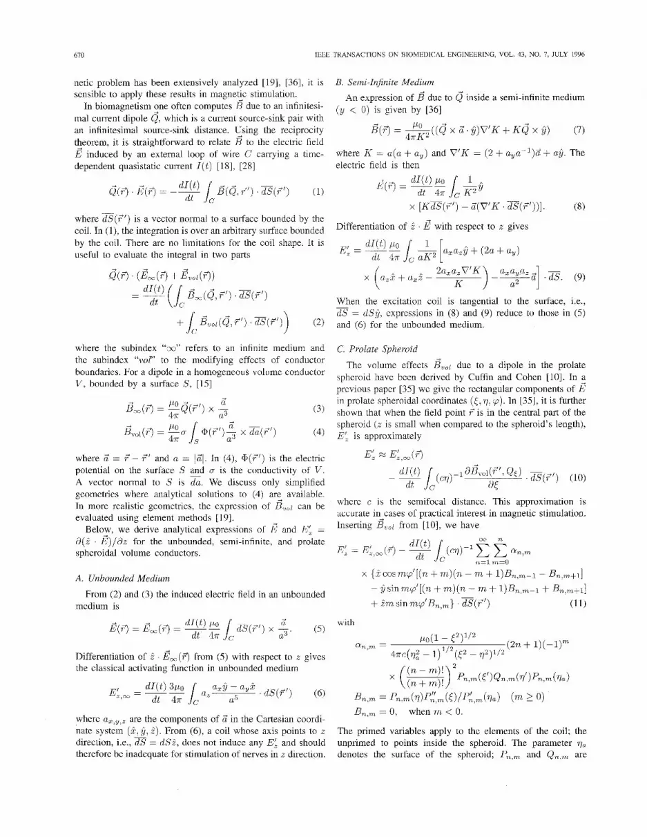
Fig. 1. The induced E: due to, (a) 8-shaped, (b) edge-tangential, (c) and erect coil over an unbounded (top row), a semi-infnite (middle), and a spheroidal (bottom row) medium. The maps are 12-cm-wide planes 10 mm below the coil, which touches the surface. Projections of the coils are isutlined with solid lines. In (a) and (b), contour step is 1 kV/m2; in (c) 0.5 kV/m2. The zero contour is dotted and the negative contours are dashed. The site of maxima are shown shaded. The single coil has a radius of 5 cm and is made of 10 turns; each wing of the 8-shaped coil has a radius of 5 cm and is made of five turns. The current in the coil is assumed to increase at a rate of 100 A / p . The inserts show the geometry as seen from the direction of the positive z-axis and from top. The spheroid’s radius is 4 cm and length 50 cm.
associated Legendre functions of the first and the second kind; and PA,, and Pl,m are the first and second derivative of P,,, with respect to its argument. The relations between the Cartesian and prolate spheroidal coordinates are found, e.g., from [lo].
For the geometries that are analyzed in this work, the difference between the values obtained truncating the infinite series in (11) for n, > 25 and n > 30 is less than 2%. In all computations here the infinite series is truncated for n > 25. The integrals over the surface of the coil are computed by dividing the surface into 121 subareas.
111. COMPUTER SIMULATIONS
In the following examples we simulate the induced E and the classical activating function E: in the unbounded, semi-infinite, and spheroidal volume conductors. To further understand magnetic stimulation, we investigate the influence of various parameters on the final results.
A. Coil Arrangements
The induced EL is shown in Fig. 1 as contour maps for three basic coil arrangements (see inserts): a round 5-cm-radius coil consisting of 10 turns and positioned longitudinal-orthogonal (erect) or edge-tangential to the target nerve, and a tangential 8-shaped coil, each wing consisting of five turns having a radius of 5 cm. The rate of change of current is assumed to be 100 Alps. The coils are in direct contact with the conductor surface, when present. Depth of the computation planes is 10
mm, which is about the depth of the median nerve at elbow. The spheroid radius is 4 cm and length 50 cni.
A similar E: is induced in all three volume conductors. In particular, with the 8-shaped coil [Fig. l(a)], the pattern of E: are almost identical in all models. Only the magnitude of EL is slightly smaller in the spheroidal approximation. With the edge-tangential orientation [Fig. l(b)], the zones of high E: in the unbounded and semi-infinite models are large and about below the inner edge of the coil; in the spheroid model the zone of high E; is smaller and more central to the coil. Results from the unbounded and semi-infinite models are equal for the edge-tangential and 8-shaped coils.
The behavior of the erect coil dliffers frorn the other ar- rangements [Fig. l(c)]; the pattern and magnitudes of E: vary notably between the models. However, if the interest is to deduce the sites of activation only, one can rely upon the unbounded model: in all models tlhe extrema of E’, are at about equal locations.
B. Spheroid Size
The influence of the spheroid size is illustrated in Fig. 2. The induced E and EL are shown iin two field points for a 2- cm-radius coil consisting of 10 circular tums. ‘The field points are 10 mm below the surface just below the coil edge closest to the spheroid and 20 mm distal to it. The coil plane is tangential to and in touch with the surface, at the surface point nearest to point 1. When the spheroid radius is varied between 2.5 and 4.5 cm [Fig. 2(a) and (b)], E increases monotolnically with the spheroid radius, from 109 to 142 V/m in point 1 and from 72

612 IEEE TRANSACTIONS ON BIOMEDICAL ENGINEERING, VOL. 43, NO. I, JULY 1996
6.0 150
100 > 4.0
- "E .
\ 25 > 2; 50 $ 2.0
0.0 8
0 25 30 35 40 45 25 30 35 40 45
Spheroid radius [mm] Spheroid radius [mm]
(a) (b)
-6.0
4.0 "E 1
5
5 2 . 0 +point 1 --t point 2 w
-b
20 40 60 80 100 20 40 60 80 100 0.0
Spheroid length [cm] Spheroid length [cm]
(c) (d)
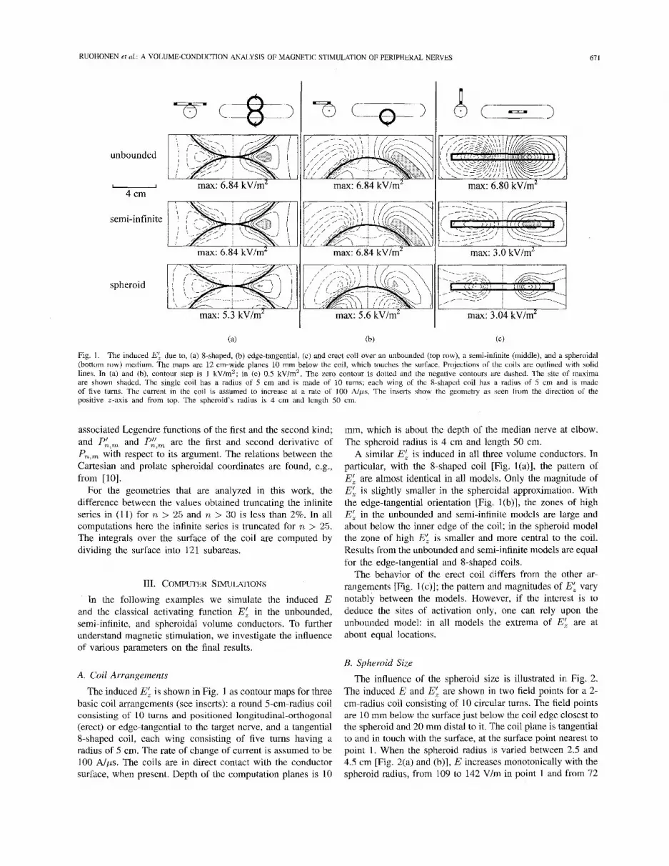
Fig. 2. Effect of the spheroid size. The induced (a) E and (b) EL are shown in two field points as a function of the spheroid radius (focal length 50 cm). The field points are just below and 20 mm distal to the edge. Likewise, the induced (c) E and (d) EL are shown as a function of the focal length (radius 4 cm). The coil is a 2-cm-radius edge-tangential coil. The rate of change of current is 100 A / p s and the coil is made of 10 turns. The field points are 1) just below the edge and 2) 10 and 3) 20 mm distal to it.
200 200 6.0
% 4.0 150 150 - c_
E >
Y 50 h 3 100 25
$100 E
43 2.0 U Y
Y 50
0 0 kl 0.0 0 IQ 20
Coil shift d [mm] 30 0 10 20 30
Coil shift d [mm] 0 10 20 30
Coil shift d [mm]
(a) (b) (c)
Fig. 3 . Effect of the coil shifting. The induced (a) E in point 1, (b) E in point 2, and (c) EL in point 2 for a 2-cm-radius coil. Results are given for the unbounded and spheroid (radius 4 cm, length 50 cm) models. When d = 0 cm, the coil is symmetrically over the limb, and is then shifted in the direction perpendicular to the limb when d grows. Point 1 is below the coil center (when d = 0 cm) and point 2 is 20 mm distal to it. Other details as in Fig. 2. Note that point 2 corresponds to point 3 in Fig. 2.
to 101 Vlm in point 3. Likewise, EL increases from 3.7 to 4.5 kV/m2 in point 3. In point 1 EL vanishes.
The effect of the spheroid length on the induced E and EL is studied in Fig. 2(c) and (d). The focal length is varied between 30 and 100 cm and E and EL are computed in three points: 1) below the edge, 2) 10 mm distal to the edge, and 3) 20 mm distal. Otherwise the geometry is the same as in Fig. 2(a) and (b). Both E and EL increase with the spheroid length. The variation in E is small: for instance, in point 2, E increases from 129 to 144 Vlm when the spheroid length increases from 30 to 100 cm. On the other hand, the variation in EL is notable: in point 2, EL increases from 3.4 to 4.4 kVlm2.
C. Coil Placement and Orientation
The distribution and amount of charge accumulated on the tissue-air surface depends on the coil placement and
orientation. The electric field shown in Fig. 3 is obtained when a 2-cm-radius coil is first placed symmetrically (d = 0 mm) over the limb, with the coil plane tangential to the nearest surface, and then moved in 5-mm steps in the direction perpendicular to the length of the limb. Results are shown for the spheroid and the unbounded medium. Results for the semi-infinite model are not shown since, in the special case of a tangential coil, the unbounded and semi-infinite models are equivalent.
In the spheroid, in point 1 [Fig. 3(a)] the peak E of 138 Vlm is obtained with the coil edge-tangential (d = 20 mm); in point 2 [Fig. 3(b)] the peak E of 139 Vlm is obtained with the coil symmetric-tangential (d = 0 mm). In point 2 the peak EL of 4.8 kVlm2 is obtained with the coil nearly edge- tangential (d = 15-20 mm) [Fig. 3(c)]. In point 1, E: = 0. The unbounded approximation is seen to overestimate the field

RUOHONEN et al. : A VOLUME-CONDUCTION ANALYSIS OF MAGNETIC STIMULATION OF PERIPHERAL NERVES 613
150 7-p
6 semi-infinite 50
-A- spheroid o ! I I I
0 30 60 90 Tilt angle [des]
(4
150 7-
0'- 0 30 60 90
Tilt angle [deg]
(h)
Fig. 4. Effect of the coil angle with respect to the volume surface. The induced E in the unbounded, semi-infinite, and spheroidal medium. E is plotted as a function of the angle between the coil plane and the direction perpendicular to the local surface, in two points: (a) just below the coil edge and (b) 20 mm distal to it (points one and three in Fig. 2). The coil radius is 2 cm and its edge is 5 mm above the surface. Other details as in Fig. 2.
-1 cm 6.0
j7 0 2 4 6 0 2 4 6
distal direction [cm] distal direction [cm]
(a) (b)
Fig. 5. values are plotted along a 10-mm-deep nerve parallel to the length of the spheroid. Other details as in Fig. 2.
Effect of the coil size. The induced (a) E and (b) EL due to edge-tangential coils of different radius (1-5 cm) touching the spheroid surface. The
values as compared to the spheroid: for instance, when the shift is 20 mm, E in point 1 in the unbounded volume is 176 V/m and in the spheroid 138 V/m.
The effect of the coil angle with respect to the surface has been investigated in the unbounded and semi-infinite medium, e.g., in [33]. In Fig. 4 we do this for the spheroid. The coil is first placed perpendicular to the surface so that its nearest edge is S mm above the surface. The angle between the coil and the direction perpendicular to the tissue is then varied from 0" to 90". The induced E is computed at two points 10 mm below the surface in the unbounded and semi-infinite media and in a 4-cm-radius spheroid (focal distance 50 cm). In point 1, E in the unbounded medium [Fig. 4(a)] remains unchanged, being 148 V/m; in the semi-infinite medium E = 81 V/m when the coil is erect (angle O"), increasing to 148 V/m when the coil becomes edge-tangential (angle 90"). In the spheroid, E is always significantly smaller than in other media, varying between 60 and 106 Vlm: in both points E is some 60-70% of the values in the semi-infinite medium and only some 40-65% of the values in the unbounded medium.
D. Coil Size
The coil size has an important effect on the induced E and EL. Fig. 5 plots E and E; along a fictitious nerve 10 mm below the surface for a circular edge-tangential coil whose radius varies from 1 to 5 cm. The coil has 10 turns and the rate of change of the current is 100 Nps. The spheroid radius is 4 cm and focal length SO cm. The erect coil orientation was
It is seen from Fig. 5(a) that E de:pends greatly on the coil radius and from Fig. 5(b) that for thie edge-tangential coil an ideal coil radius is some 2 cm: a larger radius coil does not produce a greater E:. Radius of commercially available coils is typically between 4 and 7 cm.
IV. EXPERIMENTAL RESULTS
Two healthy volunteers (a male iind a female) gave their informed consent for the study. Sitimulation of their me- dian nerve was obtained by electrical stimulation (ES) using constant-current square-wave pulses with a dur,ation of 0.2 ms (Dantec Counterpoint Mk2, Dantec Electronics, Skovlunde, Denmark) and by magnetic stimulation (Cadwell MES- 10, Cadwell Laboratories Inc., Kennewick, WA) a1" the elbow.
The evoked muscle responses were recorded by surface electrodes with the recording electrode placed over the abduc- tor pollicis brevis muscle and the reference electrode proximal to the phalanx of the thumb. A ground electrode was placed proximal to the recording electrode. A bandwidth from 50 Hz to 2 kHz was used.
Two Cadwell stimulator coils were applied: a prototype 8- shaped coil (each wing, 4 cm in diameter) and a standard 5-cm focalpoint coil (outer diameter 5 cm). X-ray films of the coils were used to locate the copper windings. The 8-shaped coil was approximated by 2 x 14 and the focalpoint coil by 20 circular loops of appropriate radius. The stimulator produces a biphasic current pulse, which accoirding to the manufacturer increases in the initial phase at a rate of about 150 Alps.
studied in 1291. The stimulus intensity was set betwe.en 80% and 100% of the

614 IEEE TRANSACTIONS ON BIOMEDICAL ENGINEERING, VOL. 43, NO. I , JULY 1996
Latency: 8.1 ms Amplitude 14.2 m V A
Electrical cathode
Amplitude: 14.0 mV
Fig. 6. to an anode-cathode separation of 36 mm. Results are from Subject #1.
Determnation of the anode-cathode separation of the Cadwell prototype 8-shaped coil. The measured latency shift is 0.6 ms, which corresponds
maximum. The stimulation threshold was measured only in subject #1, being 30% with the 8-shaped coil.
In all experiments we first determined the course of the median nerve and measured its conduction velocity using ES. Next, we checked that moving the stimulation electrodes in ES or the coil in MS along the nerve resulted in a smooth latency shift. This was done to exclude the possibility of the excitation taking place at so-called hot spots. Finally, the site of activation with MS was estimated by comparing the latencies of the muscle responses evoked by ES and MS. The response amplitudes were defined from peak to peak.
Experiment I Anode-Cathode Separation: To determine the activation site of the Cadwell 8-shaped coil, we follow Nilsson et al. (251 and adapt two concepts from ES: 1) virtual cathode, the zone of high -EL; and 2) virtual anode, the zone of high +EL. The virtual cathode is attributed to depolarization and anode to hyperpolarization of axon membranes. A number of authors have made experimental efforts to determine the site of excitation and anode-cathode separation in MS by comparison with ES Ill, [SI, [71, 191, [131, [201, [231, L2.51, [26], [30]. Determination of the sites of virtual cathode and anode is important to judge the performance of different coils and to locate the site of activation. We here compare experimental results with the theory.
With stimulators applying a monophasic current waveform, the cathode and anode are located experimentally by reversing the current direction or by flipping the coil with respect to its center. The spatial distance between the virtual cathode and anode can be determined since their locations are interchanged, changing the muscle response latency.
With stimulators applying an oscillating current waveform, the anode-cathode separation can be found by flipping the coil with respect to the midpoint between its virtual anode and cathode. However, the coils are usually asymmetric and the midpoint unknown. It is therefore necessary to rotate the handle of the 8-shaped coil by 180" with respect to the virtual cathode (see, Fig. 6). We used this procedure on Subject #1 and measured a conduction velocity of 60 d s , and a latency shift of 0.6 ms after rotation, giving an anode- cathode separation of 36 mm. Using (1 1) and assuming that the stimulation was performed at the threshold intensity, a theoretical value of 40 mm is obtained. This agrees well with
measurements by Maccabee et al. [23] and by Nilsson et al. [25]. They use equivalent 8-shaped coils and monophasic waveform and give experimental values of 26-43 mm and 41 & 5 mm, respectively.
Experiment 2 Activating Function: An experiment was designed to study the activating function. We discuss similar experiments elsewhere [34], but applying the unbounded model. Here, the spheroid model is used.
The Cadwell focalpoint or 8-shaped coil was placed with the coil plane tangential to the surface of the elbow at the point above the median nerve. The coil was then moved in this plane in the direction perpendicular to the nerve in steps of 5 mm and the latencies and amplitudes of the muscle responses were determined. The focalpoint coil was initially positioned with a straight segment of its housing parallel to the nerve and the right-angle tip of the coil above electrical cathode. The orientation of the 8-shaped coil was transverse: i.e., the coil handle was perpendicular to the nerve. The %shaped coil was initially positioned so that the electrical cathode was below the center of the mutual segment of the two wings.
The site of activation was estimated and converted into distance from the coil center. Next, the maximum value of -E: was computed in a window about the activation site. The window size was f 0.5 cm along the length of the arm, representing error in determining the latency and coil position. The spheroid model was used; the spheroid length was SO cm and radius equal to the radius of the elbow of individual subjects (about 4 cm for both).
Fig. 7(a) and (c) shows the measured activation sites for the %shaped (subject #1) and focalpoint (subject #2) coils, respectively. In Fig. 7(b) and (d) the response amplitudes are shown normalized to 100% as a function of the coil displacement. To study the activating function, in Fig. 7(b) and (d) the normalized values of -EL (solid lines) are drawn. For -EL to be the activating function, the solid curves should interpolate the experimental data. This is clearly not the case. In particular, with a shift of d = 0 cm, which corresponds to a symmetrically placed coil, no EL is induced in theory, yet, we observe a supramaximal response. It is possible that EL alone is not responsible for nervous activation in magnetic stimulation of peripheral nerves, but that some additional mechanism is involved.

RUOHONEN et al.: A VOLUME-CONDUCTION ANALYSIS OF MAGNETIC STIMULATION OF PERIPHERAL NERVES
g 2 - - - 1 - -
2 +- ;:: - -2 .- 6 -3 --
-4 -I
~
675
0 0 e
e e
e
0 0
-- I 1 1 I 1 I I i I 01
\ \ nerve spheroid
100
80
-60 s “40
20
0
-0.5 0 0.5 1 1.5 -3 -2 -1 0 1 2 3
(a) (h)
Distal direction [cm] Coil shift d [cm]
-3 -2 -1 0 1 2 3 -4 -3 -2 -1 0 1 2 3
(c) (d)
Distal direction [cm] Coil shift d [cm]
Fig. 7. Determination of the activating function. Results with the 8-shaped coil (subject #1) are shown in (a) and (b); results with the focalpoint coil (subject #2) in (c) and (d). The recorded sites of excitation are given in (a) and (c) when the coil is moved in the direction perpendicular to the limb (see inserts). In (b) and (d) the experimental results (dots) are compared with the theory, assuming that the activating function is -43; (solid line); E l (dotted line); or (YE: - E l (thick line). In (h) and (d) all values have been normalized to 100% of the absolute values. The maxima of -E: and E l in (b) are 9.4 kV/m2 and 360 V/m and in (d) 7.5 kV/m2 and 280 V/m. The maxima of the motor responses are 10.1 and 11.7 mV, respectively. The maxima of cyEL - E, are 363 and 335 V/m. In (b) cy = 0.0074; in (d) 01 = 0.016. The rate of change of current is 150 A / p s and the coils x e 5 mm above the conductor surface. The conductor model is a 50-cm-long and 4-cm-radius spheroid.
In a previous paper [34], we used the unbounded volume- conductor mode1 and discussed the possibility that the ad- ditional activating feature be the electric field component transverse to the nerve, E l . To further address this hypothesis, and to eliminate possible effects from the unbounded volume- conductor approximation, we computed El in the spheroid using the same procedure as when computing E:. The results are shown as dotted lines in Fig. 7(b) and (d). In the case of the 8-shaped coil [Fig. 7(b)], E l matches well with the experimental data; in the case of the focalpoint coil [Fig. 7(d)], the fit is poor.
In a further assumption let the activating function be of the form NE: - E l . Then the experimental results of focalpoint stimulation are explained very well [thick curve in Fig. 7(d)]. The factor a has a value of 0.016 m and is determined by fitting the experimental data in the least-squares sense. Using the unbounded model and the same experimental data, we found an optimal value of a = 0.024 m [34]. For the 8- shaped coil, a = 0.0074 is obtained. Neglecting the spheroid boundaries introduces an error source, but does not modify significantly the final conclusion that an additional activation mechanism is needed to describe magnetic stimulation of peripheral nerves.
On experimental grounds, it has been stated that the ex- citation takes place near the coil diameter [22], [23], [30]. Our results agree with these findings. The conventional coil orientations (like the edge-tangential focalpoint coil) cause action potentials to initiate at sites of high -E:.
In ES the stimulation threshold w (th the electrode orien- tation transverse to the length of the fiber is about 10 times higher than with the longitudinal orieni ation [3 11. For a typical ES arrangement of two electrodes 25 mm apart and a driving current of 20 mA, the model of Rattay 1271 predicts that 10 mm below the electrodes the peak electric field durkng longitudinal stimulation is some 30 V/m. A sufficient E in transverse electrical stimulation would therefore be of the order of 300 V/m. Similar magnitudes of E’ are observed during magnetic stimulation. A transverse electric field over the axon membrane hyperpolarizes the nearer side of the nerve and depolarizes the far side [31], [33]. Letting a fiber of radiucs R to be an infinitely long cylinder in a uniform transverse electric field, an approximation of the fiber’s transmenibrane potential change is AV, M 2REl [34]. For a 10-pm-radius fiber in an electric field of E l = 500 V/m, one obtains AV, = 10 mV.
v. DISCUSSION AND CCINCLUSION
We have developed an analytical model that can be used to calculate the excitation sites in magnetic stimulation of pe- ripheral nerves. The model can be extended for amy coil shape and placement. The presented results apply for arrangements that are geometrically identical except for size. Both E and E; scale linearly with the rate of change of the current. The model gives a highly simplified description of a limb and to examine the effects of the bones, a numerical model is most probably required. The great advantage of an arialytical model is in that parameters can be easily modified to study their influence on
616 IEEE TRANSACTIONS ON BIOMEDICAL ENGINEERING, VOL. 43, NO. I, JULY 1996
the final results. This is particularly true when analyzing the effects produced by different geometries and relative locations of medium and coil.
In this paper, we first discussed the modifying effects attributed to the volume-conductor shape that approximates the tissue enclosing the target nerves. The comparison included an unbounded, a semi-infinite, and a prolate spheroidal volume- conductor shape. When the interest is to predict the site of activation only, the unbounded model gives results similar to the spheroid model. However, the use of an oversimplified model can give erroneous estimates of magnitudes of the induced fields.
The influence of several parameters was investigated. It was found that both E and EL grow with the spheroid radius and length. Especially changes in the spheroid radius modified greatly the induced electric field. The spheroid length was found to be a less important factor.
Perhaps the most crucial factors in predicting the outcome of magnetic stimulation were identified to be the relative position and orientation of the coil with respect to the nerve and the volume conductor. Moving a tangential coil in the direction perpendicular to the length of the nerve caused dramatic changes in E and E:. We emphasize that it is utterly important to define the coil orientation with respect to the local tissue surface and to use an appropriate volume-conductor approximation.
We conclude that the influence of the boundaries is smaller for coils tangential to the surface at the point nearest to the computation point. In particular, the volume effects disap- peared in the semi-infinite medium. For coils that are oriented perpendicular to the surface, the induced electric field was found to be very sensitive to the conductor shape.
The effects of coil size were analyzed in Fig. 5. As expected, the induced E is very sensitive to the coil radius. On the other hand, it was shown that the maximum magnitude of EL is almost equal for 2-cm-radius and 4-cm-radius coils. This is an important result since small coils have a small inductance and are usually preferable over large coils.
In the experimental part of this work, we computed the spatial separation between the virtual anode and cathode. It is a useful measure to compare different coils. The theory agrees with experiments, although detailed comparison is difficult, since determination of the exact coil placement is troublesome. The anode-cathode separation, and hence also the excitation site, depend on the stimulus intensity and nerve depth [29]. In addition, fiber size has been stated to have influence on the site of excitation [9]. In many experiments the lacking anode-cathode separation can be explained by an oscillating current waveform, inhomogeneities in the tissue [22], and discontinuous latency jumps [25]. Especially in stimylation of nerves at the wrist, the bones may cause focusing of E and thus so-called hot spots where excitation takes place regardless of variations in coil placement. This has been observed in nerve root stimulation, where excitation takes place near the nuclear foramen independently of the coil placement [6].
Our results agree only partially with the predictions of the classical cable theory studies that the activating function of long and straight nerves is -EL. We observed supramaximal
muscle responses with such placements of the excitation coils that theoretically induce no -E: at the location of the nerve. This is not a new finding [9], [17], 1211, [26]. The finding is in contrast with classical cable theory studies [27], [31], [32].
We proposed that the activating function in magnetic stim- ulation may be a combination of E; and of the component of electric field E’ perpendicular to the nerve. The volume conductor modeling assumed that the nerve is uniform along its length and lies in a straight line parallel to the major axis of the prolate spheroid. Although we located the course of the median nerve, it is possible that the nerve is not completely straight and a small, but significant, EL is induced also when it is absent in theory. In addition, an analysis of fiber bundles would be required for full understanding of the situation as well as an active membrane model. We applied a stimulator with an oscillating current waveform, which complicates the analysis of the activating function. Finally, inhomogeneities are a possible explanation for the observations. They may cause local focusing of both El and -E:. Therefore, in vitro studies are required to fully address this point, to eliminate possible effects from inhomogeneities and changes in nerve depth.
It is difficult to extend this model to apply for brain stimulation since the cortical cells are short and curved. However, we feel that understanding of peripheral nerve stimulation is a necessary step toward understanding of brain stimulation.
REFERENCES
V. E. Amassian, P. J. Maccabee, and R. Q. Cracco, “Focal stimulation of human peripheral nerve with the magnetic coil: A comparison with electrical stimulation,” Exp. Neurol., vol. 103, pp. 282-289, 1989. A. T. Barker, I. L. Freeston, R. Jalinous, and J. A. Jarratt, “Magnetic stimulation of the human brain and peripheral nervous system: An introduction and the results of an initial clinical evaluation,” Neurosurg., vol. 20, pp. 10G109, 1987. P. J. Basser, R. Wijesinghe, and B. J. Roth, “The activating function for magnetic stimulation derived from a three-dimensional volume conductor model,” IEEE Trans. Biomed. Eng., vol. 39, pp. 1207-1210, 1992. N. M. Branston and P. S. Tofts, “Analysis of the distribution of currents induced by a changing magnetic field in a volume conductor,” Phys. Med. B i d , vol. 36, pp. 161-168, 1991. T. C. Britton, B.-U. Meyer, J. Herdmann, and R. Benecke, “Clinical use of the magnetic stimulation in the investigation of peripheral conduction time,” Muscle and Nerve, vol. 13, pp. 39-06, 1990. S. Chokroverty, D. Flynn, M. Picone, H. Chokroverty, and J. Belsh, “Magnetic coil stimulation of the human lumbosacral vertebral column: Site of stimulation and clinical applications,” Electroenceph. Clin. Neurophysiol., vol. 89, pp. 54-60, 1993. D. Claus, N. M. F. Murray, A. Spitner, and D. Flugel, “The influence of stimulus type on the magnetic excitation of nerve structures,” Electroenceph. Clin. Neurophysiol., vol. 75, pp. 342-349, 1990. D. Corson and P. Lorrain, Introduction to Electromagnetic Fields and Waves. D. Cros, T. Day, and B. Shahani, “Spatial dispersion of magnetic stimulation in peripheral nerves,” Muscle and Nerve, vol. 13, pp. 1076-1082, 1990. B. N. Cuffin and D. Cohen, “Magnetic fields of a dipole in special volume conductor shapes,” IEEE Trans. Biomed. Eng., vol. BME-24, pp. 372-381, 1977. D. Durand, S. Ferguson, and T. Dalbasti, “Effect of surface boundary charge on neuronal magnetic stimulation,” IEEE Trans. Biomed. Eng., vol. 39, pp. 58-64, 1992. K. P. Esselle and M. A. Stuchly, “Quasistatic electric field in a cylindrical volume conductor induced by external coils,” IEEE Trans. Biomed. Eng., vol. 41, pp. 151-158, 1994.
San Francisco, CA: Freeman, 1962.

611 RUOHONEN et ul.: A VOLUME-CONDUCTION ANALYSIS OF MAGNETIC STIMULATION OF PERIPHERAL NERVES
31 B. A. Evans, W. J. Litchy, and J. R. Dauhe, “The utility of magnetic stimulation for routine peripheral nerve conduction studies” Muscle and Nerve, vol. 11, pp. 1074-1078, 1988.
1141 B. A. Evans, “Magnetic stimulation of the peripheral nervous system,” J. Clin. Neurophysiol., vol. 8, pp. 77-84, 1991.
11.51 D. Geselowitz, “On the magnetic field generated outside an inhomoge- neous volume conductor by internal sources,” IEEE Trans. Mugn., vol.
1161 F. Graudori and P. Ravazzani, “Magnetic stimulation of the motor cortex-Theoretical considerations,” IEEE Truns. Biomed. Em. , vol. 38,
[36] J. Sarvas, “Basic mathematical and electromagnetic concepts of the hiomagnetic inverse problem,” Phys. Med. Biol., vol. 32, pp. 11-22, 1987.
MAG-6, pp. 346-347, 1970.
pp. 180-191, 1991. [17] M. Hallett, L. G. Cohen, J. Nilsson, and M. Panizza, “Differences
between electrical and magnetic stimulation of human peripheral nerve and motor cortex,” in Magnetic Stimulation in Clinical Neurophysiology, S. Chokroverty, Ed. Stoneham, MA: Butterworth, 1990, pp. 275-287.
1181 L. Heller and D. B. van Hulsteyn, “Brain stimulation using electromag- netic sources: Theoretical aspects,” Biophys. J. , vol. 63, pp. 129-138, 1992.
[19] M. Hamalainen, R. Hari, R. J. Ilmoniemi, J. Knuutila, and 0. V. Lounasmaa, “Magnetoencephalography-Theory, instrumentation, and applications to noninvasive studies of the working human brain,” Rev. Modern Phys., vol. 65, pp. 413-497, 1993.
1201 B. Lotz, J. Dunne, and J. Daube, “Preferential activation of muscle fibers with peripheral magnetic stimulation of the limb,” Muscle and Nerve, vol. 12, pp. 636-639, 1989.
[21] P. J. Maccabee, V. E. Amassian, R. Q. Cracco, L. P. Eberle, and A. P. Rudell, “Mechanisms of peripheral nervous system stimulation using the magnetic coil,” Electroenceph. Clin. Neurophysiol, Suppl. 43, pp. 344-361, 1991.
[221 P. J. Maccabee, V. E. Amassian, L. Eberle, A. Rudell, R. Q. Cracco, K. Lai, and M. Somasundrum, “Measurement of the electric field induced into inhomogeneous conductors by magnetic coils: Application to human spinal neurogeometry,” Electroenceph. Clin. Neurophysiol., vol. 8 1, pp. 224-237, 1991.
[23] P. J. Maccabee, V. E. Amassian, L. Eberle, and R. Q. Cracco, “Mag- netic coil stimulation of straight and bent amphibian and mammalian peripheral nerves in vitro: Locus of excitation,” J. Physiol., vol. 460, pp. 201-219, 1993.
1241 S. Nagarajan, D. Durand, and E. Warman, “Effects of induced electric fields on finite neuronal structures: A simulation study,” IEEE Trans. Biomed. Eng., vol. 40, pp. 1175-1188, 1993.
[2S] J. Nilsson, M. Panizza, B. J. Roth, P. J. Basser, L. G. Cohen, G. Caruso, and M. Hallett, “Determining the site of stimulation during magnetic stimulation of a peripheral nerve,” Electroenceph. Clin. Neurophysiol.,
1261 R. Olney, Y. So, D. Goodin, and M. Aminoff, “A comparison of magnetic and electrical stimulation of peripheral nerves,” Muscle and Nerve, vol. 13, pp. 957-963, 1990.
[27] F. Rattay, “Modeling the excitation of fibers under surface electrodes,” IEEE Trans. Biomed. Eng., vol. 35, pp. 199-202, 1988.
[28] P. Ravazzani, F. Grandori, A. Piavani, and M. G. Vardanega, “Intracra- nial electric fields produced by magnetic stimulation in a spherical model.” in Proc. 14th Ann. Int. Conf IEEE EMBS. Paris. France, Oct.
vol. 8.5, pp. 253-264, 1992.
Jarmo Ruohonen (S’93) was horn in Tuupovaara, Finland, on October 8, 1968. He received the M Sc degree In engineering from the Helsinki University of Technology, F i l m d , in 1993. He is currently a postgraduate student at the same university.
Since 1992, he h.as worked for part of the year in the Department of Biomedical Engineering of the Polytechnic of Milan, Italy In 1994, he joined the BioMag Laboratory of the Helsinki University Central Hospital, Finland, as a Biomedical Engineer His interests include noninvasive stimulation of the
human brain and magnetic source imaging Currently, his main project is focused on computerised stimulus targeting in magnetic brain stimulation.
Mr Ruohonen is a student member of the IEEE Engineering in Medicine and Biology Society and of the Europedn Society for Engineering and Medicine
Paolo Ravazzani was horn in Milan in 1961. He re- ceived the doctoral degree in electronic engineering from the Polytechnic of Milan m 1988 and joined the Department of Electronics (now Department of Biomedical Engineering) of the Polytechnic of Milan in 1988.
His researches concern analysis and modeling of the techniques of magnetic stimulation of the nervous system, otoacoustic ermssions, and tech- niques of signal processing for EEG and evoked potentials and multiparametric investigation of the
speech motor system
29-Nov 1 , 1992, pp 1411-1414 1291 P. Ravazzani, J Ruohonen, and F Grandori, “Magnetic stimulation
of peripheral nerves. Computation of the induced electric field in a cylinder-like structure,” Advances zn Eng Software, vol 22, pp. 29-35, 1995.
[30] M. Ravnborg, M. Bhckenberg, and K. Dahl, “Significance of magnetic coil position in peripheral motor nerve stimulation,” Muscle and Nerve, vol. 13, pp. 681-686, 1990.
[3 11 J . P. Reilly, “Peripheral nerve stlmulatlon by induced electric currents: Exposure to time-varying magnetic fields,” Med., Biol. Eng., Comput., vol. 27, pp. 101-110, 1989.
1321 B. J. Roth and P. J. Basser, “A model of the stimulation of a nerve fiber by electromagnetic induction,” IEEE Trans. Biomed. Eng., vol. 37, pp. 588-597, 1990.
“A theoretical calculation of the electric field induced by magnetic stimulation of a peripheral nerve,” Muscle and Nerve, vol 13, pp 734-741, 1990
1341 J . Ruohonen, M. Panizza, J. Nilsson, P. Ravazzani, and F. Grandori, “Transverse-field activation mechanlsm in magnetlc stlmulatlon of pe- ripherdl nerves,” Electroenceph. Clin. Neurophysiol., in press.
[35] J Ruohonen, P Ravazzani, and F Grandori, “An analytical model to predict electric field and excltation zones due to magnetic stimulation of peripheral nerves inside limbs,” IEEE Truns. Biomed. Eng., vol. 42, pp. 158-161, 199.5.
Jan Nilsson (M’83, CtM9.5) was born in Stege, Den mark in 1950. He received the B.S.E.E degree from the Technical Univerldy of Copenhagen (Teknikum) in 1977
From 1977-1982, he was a Research Assistant in the Neuromuscular Research Laboratory at the University Hospital (Rigshospitallet), Copenhagen, Denmark. From 1982-1983, he was a Visiting Guest Worker in the Laboratory of Electromyography, NINCDS, National Institutes of Health, Bethesda, MD. From 1983-1988, he was a Visiting Asso-
ciate in the H”n Motor Control Section, NINDS, NIH, Bethesda, MD From 1988-1991, he was in the Biomedical ering S-rvice, “Salvatore
[33] B J Roth, L G. Cohen, M. Hallett, W. Friauf, and P. J Basser, Maugeri” Foundation, Neuromuscular Rehab Center of Campoli Italy, and since 1991 he has been the Hedd of the Laboratory of Biomedical Engineering, “Salvatore Maugen” Foundation, Neuromuscular Rehabilitation Center of Caste1 Goffredo (MN), Italy. His research inlterests are signal processing especially applied to EMG signals, magnetic stimulation, and different ways to actlvate peripheral nerves
Mr. Nilsson was awarded grauts under the Denmark-America Foundation to participate in the Visiting Guest Worker program at the NIH, Bethesda, MD Recently he has been awarded grants from the Gangstedfonden, Copenhagen, Denmark, to continue research on EMG data alcquisition/analysis and studies on peripheral nerve time constants

678 IEEE TRANSACTIONS ON BIOMEDICAL ENGINEERING, VOL. 43, NO. 7, JULY 1996
Marcela Panizza was born in Cordoba, Argentina, in 1954 She received the M D degree from the School of Medicine, University of Buenos Aires in
1977, and completed in 1983 the residency program in neurology, from J M Rdmos Mejia Hospital, University of Buenos Ares In 1990 she convahdated the M D degree at the University of Naples, Italy
From 1985-1986, she was granted a WHO Scholarship to perform neu- romuscular research in the Clinical Electrophysiology Section of the J M Ramos Mejia Hospital, Buenos Aires From 1986-1988, she was a Visiting Fellow in the Human Motor Control Section, NINDS at the National Institutes of Health, Bethesda, MD From 1988-1991, she was a research Fellow in the Laboratory of Clinical Neurophysiology, “Salvatore Maugeri” Foundation, Neuromuscular Rehabilitation Center of Campoh (BN), Italy She is currently the Head of the Laboratory of Clinical Neurophysiology, “Salvatore Maugen” Foundation, Neuromuscular Rehahilitation Center of Caste1 Goffredo (MN), Italy. Her research interests are human motor control, electromyography, and magnetic stimulation.
Dr. Panizza is a Board Certified Neurologist in Argentina, member of the Argentine Neurological Society, and a Corresponding Associate of the American Academy of Neurology
Ferdinand0 Grandori was born in Milan, Italy, in 1946. He received the doctoral degree in electronic engineenng from the Polytechnic of Milan, Italy, in 1970, and joined the Department of Electronics of the Polytechnic of Milan in 1970
Since 1976 he is a researcher of the Italian National Research Council (C N R ) at the Centre of System Theory, Milan, Italy His research in- terests include techniques of signal processing for evoked potentials, methods of source localization for bioelectrical signals, models of auditory func-
tions, otoacoustic emssions, and magnetic stimulation of the nervous system
Gabriella Tognola was born in 1969. She received the doctoral degree in electronic engineering from the Polytechnic of Milan, Italy, in 1993.
Since 1993, she joined the Department of Biomedical Engineering of the Polytechnic of Milan. Her primary research interests are in digital signal processing of biomedical signals, analysis and modeling of EEG and otoacoustic emissions, and magnetic stimulation of the nervous system.
Recommended