
AIAA 2002-1426
STRUCTURE AND PROPERTIES OF CARBON NAN-OTUBE REINFORCED NANOCOMPOSITES
Frank K. Ko, Sakina Khan, Ashraf Ali, Yury Gogotsi, Nevin Naguib Guoliang Yang and Christopher Li
Drexel University, Philadelphia, PA, 19104 Hideo Shimoda and Otto Zhou,
University of North Carolina, Chapel Hill, NC 27599Michael J. Bronikowski
Jet Propulsion Laboratory, California Institute of Technology, Pasadena, CA 91109Richard E. Smalley
Rice University, Houston, TX 77005; andPeter A. Willis
Univ. of Calif., Los Angeles, CA 90095
Copyright©2002 The American Institute of Aeronautics and Astronautics Inc. All rights reserved.
AbstractCarbon nanotubes (CNT) possess many unique characteristics that promise to revolutionize the world of structural ma-terials resulting in significant impact on our capability to build lighter, smaller and higher performance structures for aerospace and many other industrial ap-plications. When the CNT are aligned, micromechanical studies showed the po-tential of an order of magnitude increase in mechanical properties comparing to the state of the art carbon fiber rein-forced composites. The co-electrospin-ning process is introduced as a pathway to realize this potential by aligning and carrying the CNT in the form of nanocomposite fibrils; thus forming the precursor for linear, planar and 3D fiber assemblies for macrocomposites. In this study, SWNT were purified and dis-persed in polyacrylonitrile
solution for co-electrospinning into nanocomposite fibrils. The structure, composition and physical properties of these composite fibrils were character-ized by Raman spectroscopy, TEM, AFM, and TGA.
Key words Carbon nanotube, co-electrospinning, Raman spectroscopy, AFM, TEM, TGA
1. Introduction Since the discovery of carbon nanotubes (CNT) by Iijima in 1991 [1], increasing attention has been attracted to this newly emerging material due to its remarkable mechanical and electrical properties [2, 3]. Based on its unique properties, many applications of CNT have been proposed including quantum wires, tiny electronic devices [4, 5], heterojunction devices, electron emitters [6], nanotube tips for scanning probe microscope [7], etc. One
of the most intriguing applications of CNT is the polymer/CNT nanocompos-ites [8-13]. The superb mechanic prop-erty of CNT makes them ideal candidate as fillers in high strength, lightweight polymer composite. Polymers such as epoxy [10], thermoplastics [11], gels [12], as well as Poly (methyl methacry-late) (PMMA) [13] have been used as the matrix. However, the developments in polymer/CNT nanocomposite has been limited by the problems with the dispersion of the fillers as well as the load transfer across the CNT polymer in-terface due to the atomically smooth CNT surface. Well-aligned CNTs are also preferred since they are highly an-isotropic. A number of methods have been used to achieve highly oriented CNT. [14-16]. All these methods are limited to microscale and are not suitable for commercial composite manufactur-ing process.Based on a recent NASA study by Harris et al. [17] using micromechanics compu-tation, it was concluded that an order of magnitude increase in specific modulus can be achieved with SWNT composites. Despite their promise, most current stud-ies are limited to the physics and chem-istry of individual SWNTs. There is lim-ited knowledge on the properties of macroscopic materials comprising SWNTs as the basic building blocks for macroscopic structures. It is still not clear whether the superb properties ob-served at the individual molecular level can be scaled up to the macroscopic structures. In order to realize the exciting potential of SWNTs, there is a need for processing methodologies and robust manufacturing technologies to convert SWNTs to macroscopic structures. In a recent paper [ 18 ] by Ko et al, the con-cept of formation of super carbon nan-otube fibril (SCF) by the electrospinning
2American Institute of Aeronautics and Astronautics

process was introduced. In this paper the HiPco single wall carbon nanotubes (SWNT) dispersed in a polyacrylonitrile matrix are used to demonstrate the valid-ity of the SCF concept.
2. Co-electrospinning of SWNT/PAN
HiPco single wall nanotubes (SWNTs) obtained from Rice University, were pu-rified, dispersed and mixed with Poly-acrylonytrite (PAN) and co-electrospin-ning was done to produce the SWNT fibrils. The purification process for the
HiPco SWNT is necessary because of the iron catalysts entrapped in carbon shells of the nanotubes must be re-moved. The purification process calls for multiple steps of oxidation, cleaning, rinsing and filtering according to the flow diagram shown in Fig. 1. In the same figure TEM images of the SWNT/PAN fibril are shown revealing a diamond pattern of the SWNT s. Some ligaments of the SWNT/PAN 5 nm in diameter were also observed.
Figure 1. Processing Flow of SWNT/PAN Composite Fibrils and their TEM images.
3American Institute of Aeronautics and Astronautics

The electrospinning process is a non-me-chanical method capable of the forma-tion of nanoscale fibers electrostatically from polymer solutions or melts. Elec-trostatic generation of ultrafine fibers (“electrospinning”) has been known since the 1930’s [18,19] This technique has been recently rediscovered for appli-cations such as high performance filters [21] and for scaffolds in tissue engineer-ing [22] that utilize the unique character-istics of the high surface area (~ 103 m2/gm) provided by the fibers. In this tech-nique, a high electric field is generated between a polymer fluid contained in a glass syringe with a capillary tip and a metallic collection screen. When the voltage reaches a critical value, the charge overcomes the surface tension of the deformed drop of the suspended polymer solution formed on the tip of the syringe and a jet of ultrafine fibers is produced. The electrically charged jet
undergoes a series of electrically in-duced bending instabilities during its passage to the collection screen that re-sults in the hyper-stretching of the jet. This stretching process is accompanied by the rapid evaporation of the solvent molecules that reduces the diameter of the jet in a cone shape radius. The dry fibers are accumulated on the surface of the collection screen or a collecting drum, resulting in a non-woven mat or linear assembly of nano to micron diam-eter fibers. The process can be adjusted to control the fiber diameter by varying the charge density (~1.5KV/cm was em-ployed) and polymer solution concentra-tion, while the duration of electrospin-ning controls the thickness of fiber depo-sition. A schematic drawing of the elec-trospinning process of SWNT and PAN is shown in Figure 2. .
V
CNTs in Polymer Solution
10-100nm
1-10 nmCNT
Nanocompositefibrils
Polymer jet
Figure 2. Co-electrospinning of SWNT/PAN Fibril and Fibrous Structures.
3. Characterization of CNT Fibril
3.1 Raman Spectroscopy
Raman spectroscopy analysis has been conducted on fiber spun with and with-out single wall nanotubes (SWNT) as shown in Figure 3. These spectra were recorded using a Renishaw Ramanmi-crospectrometer Ramascope 1000 by us-
ing a diode laser (780nm excitation wavelength, 12 W/cm2), which corre-sponds to the equivalent photon energy of 1.58eV. Typical peaks of SWNT’s can be seen in the fiber spun with nan-otubes, which serves as a direct confir-mation of the successful filling of poly-mers with the nanotubes.
4American Institute of Aeronautics and Astronautics

The most intense bands in the Raman spectra of single wall carbon nanotubes are the radial breathing mode (RBM) near 180 cm-1 and the modes between 1500-1600 cm-1 associated with the tan-gential displacement of C-C bond
stretching motions of the nanotubes. RBM belongs to the identity representa-tion (A1g or A1 radial band), while 1500-1600 cm-1 range belongs to E1g or E2g
symmetry (tangential band) [23]
Figure 3. Raman Spectra of PAN and SWNT/PAN at 780 nm Excitation
According to the theoretical predictions RBM frequency is inversely proportional to the tube diameter, without any depen-dence on the chiral angle. On the other hand, it has been also shown that the fre-quencies and the number of the Raman active modes between 1500-1600cm-1
depend on the diameter and the chirality of the nanotube. However, within each type of nanotube, the modes in the 1580-1590 cm-1 range are expected to be very weakly dependent on the nanotube diam-eter, by perhaps an order of magnitude less than for the case of the diameter de-pendence of the RBM.From the results shown here, the most intense band in the Raman Spectra of SWNT-filled fiber is the radial breath-ing mode (RBM) near 270 cm-1. The presence of at least 6 RBM peaks is ob-
served in the range from130-275 cm-1. This corresponds to a very large diame-ter distribution shown by the low-fre-quency bands and confirmed by the broader splitting of the E2g2 graphite mode, which simply means that the sam-ple has different tube diameters.
3.2 Thermal Stability by Ther - mal Gravimetric Analysis
The CNT contents in the PAN nanofibers can be detected by the ther-mogravimetry method. Both pure PAN r and PAN-CNT nanofibers were heated in the air atmosphere at a rate of 20C/min. Decomposition of PAN takes place at 308C for the pure PAN nanofiber and 325C for the PAN-CNT nanofiber, indi-cating that CNT in the PAN nanofibers
5American Institute of Aeronautics and Astronautics

increases PAN’s thermal stability. The difference of the remaining weight be-tween these two samples (56.8% for pure PAN and 61.2% for PAN-CNT) at the plateau region (around 330C) is due to the CNT contents in the PAN-CNT nanofibers. Assuming that the same de-composition mechanism for these two samples, (thermal pyrolysis of PAN is relatively complicated; since our main
goal is to determine the CNT contents in the nanofibers, the detailed mechanism will not be discussed here)[24,25] the CNT content in the PAN-CNT can there-fore be calculated to be 10 wt %. The results suggest that 10% of CNT in the PAN-CNT nanofibers increases the de-composition temperature of PAN nanofibers by 17C.
Figure 4. TGA analysis of PAN (dotted line) and PAN-CNT (solid line) nanofibers in air.
3.3 Atomic Force Microscopy
The atomic force microscope (AFM) of-fers the opportunity not only to charac-terize the surface topography of the fibers but also to investigate their me-chanical, electrical and thermal proper-ties, with the utilization of appropriate probes. Since the structural, mechanical, electrical and thermal properties of the SWNT/PAN fibrils are expected to be highly anisotropic and heterogeneous, the high spatial resolution of AFM makes it an ideal tool to measure these properties locally. These local proper-ties will reveal certain microscopic
mechanisms for the observed behaviors of these fibers on the macroscopic scale.
Surface structure characteriza-tion – Both tapping-mode and contact-mode AFM imaging will be used to characterize the surface structures of the SWNT/PAN fibers. AFM imaging re-quires a flat substrate and a sparse distri-bution of fibers firmly attached to the substrate. We have found that depositing the fibers directly on a fresh mica sur-face during the electrospinning produces satisfactory specimens for AFM imag-ing. Theattachment of the fibers to the mica sub-strate is strong enough to withstand
6American Institute of Aeronautics and Astronautics
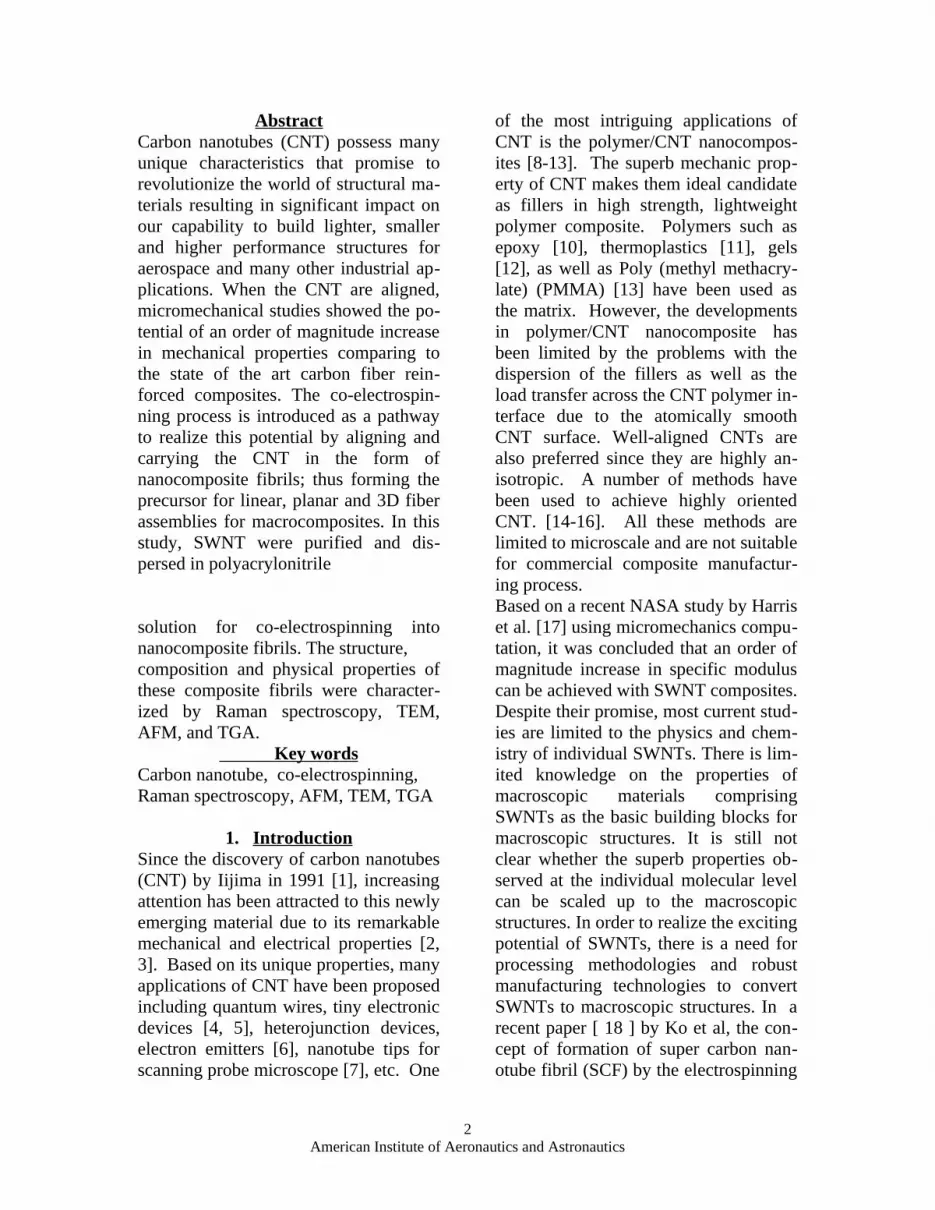
imaging. Preliminary results show that PAN fibers and the SWNT/PAN fila-ments have distinctly different surface
structures, as shown in figures 5a and 5b.
Figure 5. AFM images of (a) PAN fiber; (b) SWNT/PAN Fibril
The questions that can be addressed us-ing AFM imaging include how the inclu-sion of SWNTs changes the surface mor-phology of the fiber, how the SWNTs are oriented in the fibers, and how the fibers interact with each other at the crossover points. Since AFM can image samples submerged in liquids, the effects of different solvents on the fiber properties can be monitored and measured.
Mechanical properties mea-surements - The AFM has been used to investigate the mechanical properties of carbon nanotubes [26-29]. We have used this approach to measure the me-chanical properties of the SWNT/PAN fibers. In such an experiment, the fibers are first imaged, and the AFM tip is then positioned on top of the fiber at the point of interest, and the sample surface is then raised as shown in figure 6(a).
The force is obtained from the deflection of the cantilever d, the amount of fiber indentation/deformation z can be ob-tained from the difference of the sample height increase h and d: z=h - d. The elastic modulus of the fiber can be evaluated based on these measured pa-rameters using the approach of Kracke and Damaschke [27]. The method uti-lizes the relationship dF/d(z) = (21/2)E*A1/2, where A is the contact area, E* is the effective Young’s modu-lus of the contact as defined by: 1/E*=(1-
2)/E1+(1- 22)/E2. Here, E1, E2
and 1 and 2 are the elastic moduli and the Poisson’s ratios of the sample and the tip. Figures 6(b) and 6(c) show the results of mechanical property measure-ments on SWNT/PAN and PAN fibers. Mica was used as a standard since its elastic modulus has been determined the same method [27].
7American Institute of Aeronautics and Astronautics

Figure 6. (a) Schematic for elasticity measurement. (b) Cantilever deflection vs. sample height in a cycle of compression and relaxation. (c) Load vs. indentation curves
The fibrils show a non-linear behavior in the load versus indentation plot, as shown in figure 6(c). The cause of this non-linear behavior of the load-deforma-tion curves is still under investigation. Using the first linear region in the plot (125 nN –300 nN), the Young’s modulus of the SWNT/PAN fibril has been esti-mated to be ~2.0GPa, while that of the PAN fibrils has an approximate value of ~1.0 GPa. Although there is still a long way from realizing the theoretical SWNT/PAN composite modulus of 100GPa, considering the tensile modulus of the unfilled PAN nanofibers of ~ 1GPa, the reinforcement effect is quite remarkable with only less than 10% weight of SWNT was added showing a ductile mode of failure. For data show-ing in figure 6, a silicon nitride can-tilever with a spring constant of 0.58 N/m was used. Each curve in figure 6(c) is the average of several curves mea-sured on the same material. The values of tip parameters used in the estimation of the elastic modulus are: 2=0.27,
E2=130 GPa for the radius of contact area=5.0 nm.
4. Summary and Conclusions Co-electrospinning process is a viable means to produce continuous polymeric filaments filled with SWNT. Purified HiPco SWNT were dispersed in PAN solution and co-electrospun achieving a weight fraction approaching 10%. Ra-man spectroscopy and TEM images showed convincingly the presence of SWNT in the electrospun PAN fibrils. AFM images showed a rough surface of the SWNT/PAN fibril as compared to the smooth surface appearance of the PAN fibrils. TEM images further con-firm the presence of SWNT along the length of the fibrils revealing a diamond pattern of the SWNTsThe thermal stabil-ity of the SWNT/PAN was demonstrated by TGA showing greater than 15ºC in-crease in decomposition temperature comparing to PAN. Load-deformation relationship of single SWNT/PAN fibril was characterized showing a ductile
8American Institute of Aeronautics and Astronautics

mode of failure and a strong reinforce-ment effect by doubling the tensile mod-ulus with less than 10% reinforcement by weight.
5. AcknowledgementsThis work was partially supported through NASA grant NAG-101061 (Ko and Zhou). Funding from NASA , ONR and the Texas Advanced Technology program to the Smalley group is greatly appreciated.
6. References
1. D. A. Walters, L. M. Ericson, M. J. Casavant, J. Liu, D. T. Colbert, K. A. Smith, and R. E. Smalley, Elastic strain of freely suspended single-wall carbon nanotube ropes, Appl. Phys. Lett., 74, 3803-3805(1999),
2. H. Ishikawa, S. Fudetani and M. Hi-rohashi, Mechanical properties of thin films measured by nanoinden-ters, Appl. Surf. Sci. 178, 56-42(2001).
3. B. Kracke and B. Damaschke, Mea-surement of nanohardness and na-noelasticity of thin gold films with scanning force microscope, Appl. Phys. Lett. 77, 361-363(2000).
4. T. Hertel, R. Martel and P. Avouris, Manipulation of Individual Carbon Nanotubes and Their Interaction with Surfaces, J. Phys. Chem. B 102, 910-915(1998).
5. H. Dai, E.W. Wong and C. M. Lieber, Probing Electrical Transport in Nanomaterials: Conductivity of Individual Carbon Nanotubes, Sci-ence, 272, 523-526(1996).
6. T. Tombler, C. Zhou, L. Alexseyev, J. Kong, H. Dai, L. Liu, C. S. Jayan-thi, M. Tang and S. Wu, Reversible electromechanical characterization of carbon nanotubes under local-probe
manipulation. Nature, 405, 769-772(2000).
7. P.J. de Pablo, M.T. Martınez, J. Colchero, J. Gomez-Herrero, W.K. Maser, A.M. de Benito, E. Munoz and A.M. Baro, Electrical character-ization of single-walled carbon nan-otubes with Scanning Force Mi-croscopy, Mater.Sci. Eng. C15, 149–151(2001).
8. L. Cai, H. Tabata and T. Kawai, Self-assembled DNA networks and their electrical conductivity, Appl. Phys. Lett. 77, 3105-3106(2000).
9. M.C. Hersam, A.C. F. Hoole, S.J. O’Shea, and M.E. Welland, Poten-tiometry and repair of electrically stressed nanowires using atomic force microscopy, Appl. Phys. Lett. 72, 915-917(1998).
10. Facundo Ruiz, W. D. Sun, and Fred H. Pollak and Chandra Venkatraman, Determination of the thermal con-ductivity of diamond-like nanocom-posite films using a scanning thermal microscope, Appl. Phys. Lett. 73, 1802-1804(1998).
11. G.B.M. Fiege, A. Altes, R. Heider-hoff and L.J. Balk, Quantitative ther-mal conductivity measurements with nanometre resolution, J. Phys. D 32, L13–L17(1999).
12. S. Gomes, N. Trannoy and P. Grossel, DC thermal microscopy: study of the thermal exchange be-tween a probe and a sample, Meas. Sci. Technol. 10, 805–811(1999).
13. O. Laurie, D.E. Cox, and H.D. Wag-ner. Bucking and collapse of embed-ded carbon nanotubes. Appl Phys. Lett., 81(8):1638-1641,. 1998.
14. C. Bower, R. Rosen, L. Jin, J. Han, and 0. Zhou. Deformation of carbon nanotubes in nanotubular polymer composites. Phys. Lett., 74(22):3317-3319, 1999.
9American Institute of Aeronautics and Astronautics

15. L.S. Schadler, S.C. Giannaris, and P.M. Ajayan. Appl Phys. Lett., 73:3842-3844, 1999.
16. L. Jin, C. Bower, and O. Zhou, Alignment of carbon nanotubes in a polymer matrix by mechanical stretching. Appl. Phys. Lett., 73(9):1197-1199, 1998.
17. C.E. Harris, J.H. Starnes, Jr., and M.J. Shuart, An Assessment of the State of the Art in the Design and Manufacturing of Large Composite Structures for Aerospace vehicles, NASA/TM-2001-210844, April 2001
18. F.K. Ko W. B. Han , A. Rahman, H. Shimoda and O. Zhou , Carbon Nan-otube Reinforced Nanocomposites by the Electrospinning Process, Pro-ceedings, Am. Soc. for Comp., Vir-ginia Poly. Tech. Inst. September 2001.
19. A. Formhals, US Patent 1,975,504, 1934
20. J. Doshi and D.H. Reneker, Journal of Electrostatics, 35 (1995) 151.
21. P.W. Gibson, H.L. Schreuder-Gibson and D. Riven, AIChE Journal, 45 (1999) 190.
22. F.K. Ko, C.T. Laurencin, M.D. Bor-den and D.H. Reneker, “The Dynam-ics of Cell-Fiber Architecture Inter-action”, Proceedings, Annual Meet-ing, Biomaterials Research Society, San Diego, April, 1998.
23. W.H. Weber, R. Merlin. Raman Scattering in Materials Science. Springer-Verlag Berlin Heildberg 2000.
24. W. J. Burlant and J. L. Parsons Py-rolysis of Polyacrylonitrile, J. Polym. Sci. XXII, 249-256(1956).
25. J. E. Bailey and A. J. Clarke Carbon Fibre Formation—the Oxidation Treatment, Nature, 234, 529-531(1971).
26. D. A. Walters, L. M. Ericson, M. J. Casavant, J. Liu, D. T. Colbert, K. A. Smith, and R. E. Smalley, Elastic strain of freely suspended single-wall carbon nanotube ropes, Appl. Phys. Lett., 74, 3803-3805(1999),
27. H. Ishikawa, S. Fudetani and M. Hi-rohashi, Mechanical properties of thin films measured by nanoinden-ters, Appl. Surf. Sci. 178, 56-42(2001).
28. B. Kracke and B. Damaschke, Mea-surement of nanohardness and na-noelasticity of thin gold films with scanning force microscope, Appl. Phys. Lett. 77, 361-363(2000).
29. T. Hertel, R. Martel and P. Avouris, Manipulation of Individual Carbon Nanotubes and Their Interaction with Surfaces, J. Phys. Chem. B 102, 910-915(1998).
10American Institute of Aeronautics and Astronautics
Recommended


