
1
Damping Power System Oscillations by VSC-Based
HVDC Networks: A North Sea Grid Case Study
Mario Ndreko1,
Arjen A. van der Meer1, Barry. G. Rawn
2, Madeleine Gibescu
1,
Mart A. M. M. van der Meijden1&3
1. Intelligent Electrical Power Grids, Faculty of EEMCS Delft University of Technology
2. Research Division Electa , Department of Electrical Engineering (ESAT)
KU Leuven 3. TenneT TSO B.V.
Abstract— This paper introduces a control strategy for damping
of onshore power system oscillations through a voltage source
converter based HVDC offshore grid. Time domain simulations
are performed for a North Sea grid case study where the DC
grid connects two asynchronous power systems as well as
offshore wind power plants. Dynamic equivalents of the Nordic
and the UK power systems are used. Simulation results
demonstrate the capability of the VSC-based multi-terminal DC
grid to improve onshore power system small signal stability.
However, the results reveal undesired interactions between
different converters in the DC grid when some are implementing
power oscillation damping. This paper proposes a coordinated
control scheme between onshore voltage source converters and
the offshore power plant modules (PPM), to compensate for
these unwanted disturbances by making use of the available
energy from offshore wind PPMs.
Index Terms—VSC-HVDC transmission, multi-terminal DC
grid, power oscillations damping, offshore wind integration,
small-signal stability
I. INTRODUCTION
igh voltage DC transmission based on voltage source
converter technology (VSC-HVDC) is becoming a
mainstream alternative for the grid connection of
large-scale offshore wind power plant modules (PPM)
located far from shore. The controllability of VSC-HVDC
allows additional control features such as power oscillation
damping (POD) of AC-system inter-area oscillations as well
as multi-terminal VSC-HVDC (VSC-MTDC) operation
within envisaged transnational offshore grids.
This paper explores the POD functionality provided by
VSC-based HVDC systems interconnecting transnational
grids and demonstrates it on a future North Sea grid case
study. Such a situation, in which multiple synchronous areas
are involved, complicates the application of POD controllers
to VSC-HVDC units for improvement of onshore power
system small signal stability. The contribution of this paper is
to both quantify and also compensate for the perturbed DC
voltage due to adding POD controllers to the VSC-MTDC
grid. As such, the results shown in this paper could be useful
for future grid code designs that encompass transnational
offshore grids.
This study has been performed on a realistic test system,
which consists of dynamic equivalent models of the UK and
Nordic power systems [1], [2] and a five-terminal VSC-
MTDC network. This network interconnects a total amount of
800MW offshore wind power to the two synchronous areas.
The landing points are assumed to be the North Scotland
coastline and the Norwegian Southwest coastline. Both AC
systems are implemented in PSS®E using standard models
while the VSC-MTDC grid is added via a user-written
dynamic model. For the case of offshore wind power plant
modules, standard improved full converter wind turbine
models from PSS®E have been used.
The paper is organised as follows: Section II introduces the
modelling approach for VSC-MTDC networks and discusses
its main controllers. The simulation results as well as the
main discussion and analysis are presented in section III. The
conclusions are drawn in section IV.
II. MODELLING FRAMEWORK
A. Model of VSC-Based HVDC Systems for Bulk Power
System Stability Studies
A VSC terminal consists mainly of the power electronic
interface, the modulator system, the inner controller which
gives the voltage reference set points, outer controllers and
appropriate fault ride-through equipment. For this study the
DC chopper method is used for FRT of the VSC-MTDC grid.
Fig. 1 illustrates the block diagram of such a VSC terminal.
The outer controllers are responsible for setting the VSC
active and reactive current set-points. These current set-points
are the outputs of the DC voltage and active/reactive power
controllers. The phase reactor is needed to provide an angle
displacement for the vector control next to operating as a
low-pass filter for the high frequency current harmonics in
the AC terminal of the VSC. iabc, is the instantaneous current
H
This research is financially supported by both the FLOW project and
the AgentschapNL, an agency of the Dutch ministry of Economic Afairs, under the project North Sea Transnational Grid (NSTG). NSTG is a joint
project of Delft University of Technology and the Energy Research Center
of the Netherlands.
2
flowing through the phase reactor while Udc is the
instantaneous DC voltage amplitude across the DC terminal
capacitor.
The time-averaged modelling approach is commonly used
to represent VSC-based HVDC transmission systems in
power system stability studies. Note that only AC side
disturbances will be simulated. A VSC is modelled as a
controllable three-phase AC voltage source at the AC side,
while at the DC side it is modelled as a DC current injection
in parallel to the equivalent model of the HVDC cables.
=
~
PWM pulses
VSC
abci
,c abcu
DC Chopper
chR
,s abcu
LR
3
ωL
ωL
𝐾𝑝 +𝐾𝑖
𝑠
𝐾𝑝 +𝐾𝑖
𝑠 Σ
Σ
+
+
+
+
-
-
-
-
Inner Controller
qi
di
ref
di
ref
qi
,
d
c refu
,
q
c refu
abcdq
modulator
,c abcu
abcdq
di
qi
PLL
s
dcU
+
-
dcC
Fig. 1 Block diagram showing the relevant control modules of the VSC-
based HVDC system
Due to the transient and small-signal stability scope of this
research, all currents and voltages at the AC side are assumed
to contain only fundamental-frequency components and are
assumed balanced. This allows the neglect of detailed IGBT
commutation and switching modelling, and allows voltages
and currents to be represented by quasi-stationary phasors.
At the DC side, the current injection is calculated from the
active power balance between the AC and DC side. The
HVDC cables for the MTDC connection are modelled by
lumped π-equivalent models which are combined in a state-
space representation.
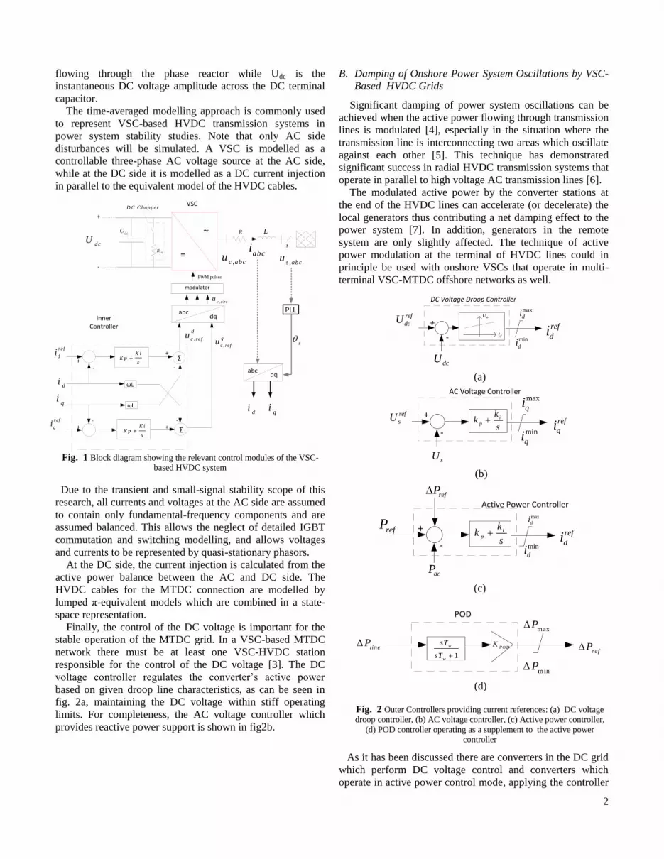
Finally, the control of the DC voltage is important for the
stable operation of the MTDC grid. In a VSC-based MTDC
network there must be at least one VSC-HVDC station
responsible for the control of the DC voltage [3]. The DC
voltage controller regulates the converter’s active power
based on given droop line characteristics, as can be seen in
fig. 2a, maintaining the DC voltage within stiff operating
limits. For completeness, the AC voltage controller which
provides reactive power support is shown in fig2b.
B. Damping of Onshore Power System Oscillations by VSC-
Based HVDC Grids
Significant damping of power system oscillations can be
achieved when the active power flowing through transmission
lines is modulated [4], especially in the situation where the
transmission line is interconnecting two areas which oscillate
against each other [5]. This technique has demonstrated
significant success in radial HVDC transmission systems that
operate in parallel to high voltage AC transmission lines [6].
The modulated active power by the converter stations at
the end of the HVDC lines can accelerate (or decelerate) the
local generators thus contributing a net damping effect to the
power system [7]. In addition, generators in the remote
system are only slightly affected. The technique of active
power modulation at the terminal of HVDC lines could in
principle be used with onshore VSCs that operate in multi-
terminal VSC-MTDC offshore networks as well.
+ref
dcU
-
dcU
max
di
DC Voltage Droop Controller
ref
di
dcU
dimin
di
(a)
+ref
sU
-
sU
ip
kk
s
max
qiAC Voltage Controller
ref
qimin
qi
(b)
+refP
-ref
di
acP
ip
kk
s
max
di
Active Power ControllerrefP
min
di
(c)
minP
POD
1
w
w
sT
sT
PODK
lineP
maxP
refP
(d)
Fig. 2 Outer Controllers providing current references: (a) DC voltage droop controller, (b) AC voltage controller, (c) Active power controller,
(d) POD controller operating as a supplement to the active power controller
As it has been discussed there are converters in the DC grid
which perform DC voltage control and converters which
operate in active power control mode, applying the controller

3
in fig. 2c. The latter converters, next to their ability to
transport constant active power, could also integrate a POD
controller, as given in fig. 2d. It modulates the active power
at the AC terminal of the VSC under post-fault conditions. In
this way, the onshore VSC contributes a net damping effect
for low frequency power system oscillations.
The classical power system stabilizer (PSS)-type POD that
has been introduced in [6] [8] has been successful in terms of
damping power system oscillations and has been applied in a
number of radial HVDC applications. However, the
application of such PSS-type POD needs careful design and
parameter selection, especially when used in (multi-terminal)
HVDC applications. A badly-tuned POD may amplify instead
of damp power system oscillations introducing thus a
negative damping effect to the onshore power system.
Another POD solution, originally adopted for the design of
power system stabilizers implemented in full converter direct
drives wind turbines [7] [8] is proposed in this paper, as
shown in fig. 2d. The controller employs a washout filter with
time constant Tw, so that the power set point is not affected in
steady-state. The input could be the speed deviation of the
closest generator or active power flow of a transmission line.
The output is used as an input to the active power controller
of the onshore VSC.
The operation of this simple POD controller is based on
basic physical considerations [7] and does not require the
design of special lead/lag compensators as in the PSS-type
POD. A typical washout time constant of 10-20s can be
applied and the only degree of freedom is the gain KPOD,
which determines the damping effect and the power system
poles displacement. Therefore, the POD can be designed for
every application without sophisticated tuning, simplifying
both the design and its application. The only necessary
constraint is the determination of the specific mode in the
system which is both observable and controllable by the
given onshore VSC. This method is further extended in
section III.D from individual onshore VSC terminal to
coordinated operation of onshore VSC and offshore wind
Power Plant Modules (PPM).
III. SIMULATION RESULTS
A. North Sea Grid Case Study
In this paper we introduce the coupling of the UK
equivalent benchmark power system model as given in [1]
with a Nordic equivalent system [2]. The generated power
from the two offshore wind PPMs (2x400 MW in this case
study) is transported onshore via the VSC-MTDC network to
both asynchronous power systems. The control of the direct
voltage in the VSC-MTDC offshore network is performed by
the two onshore VSCs of the Nordic system which both
implement the droop control shown in fig. 2a.
All generators (mainly equivalent generators that represent
areas in the UK system) are modelled by the 6th
order
standard IEEE dynamic model using dedicated parameters,
taken from [1]. This study uses standard IEEE excitation and
governing (TGOV1 & SEXS) model.
The proposed UK equivalent model exhibits various local
modes and one inter-area mode of electromechanical
oscillations. The inter-area mode is 0.5 Hz for this particular
case study, and occurs between the North part of UK system
(which represents North and South Scotland) and the South
part which represents the main and South England).
5600
6000
6100
6001
5601
acdc
ac
dc
NORDICPower
systemBenchmark
acdc
dcac
1
2
3
45
400MW Offshore Wind
Power Plant
400MW Offshore Wind
Power Plant
1001 10081002
1003 1004
1007
1005
1006
acdc
0.5Hz
6
L36, L46, L56=100kmL16, L26=20km
HVDC cable
Fig. 3 A North Sea grid case study. UK and Nordic system benchmark
models, coupled via a VSC-MTDC grid for offshore wind power and trade.
The detailed Nordic system consists of 3000 buses, 4000
branches and 1100 generators. It was reduced to an
equivalent benchmark model of 36 buses including 20 large
generators, which represent each area in the Nordic system.
Standard IEEE 6th
order models of the synchronous
generators have been used, with IEEET2 excitation system
and IEEEG0 governor models. Power system stabilizers
STAB2A are in operation at certain generators in the Nordic
system. This model is capable of reproducing the well known
inter-area modes of the Nordic system [2].
B. Analysis for a Three-Phase Fault in the UK System
Fig.4 introduces the rotor speed (SPD) response of the
generators in the UK system for a self-cleared 140 ms
symmetrical three-phase fault at bus 1007. It can be seen that
apart from the local modes (which are clearly fast damped)
there is also an inter-area mode of 0.5 Hz frequency with
poor damping.
From the time domain simulations shown in fig. 5, it can
be observed that the AC-side voltage drop at the AC terminal
of the onshore VSC at bus 1002 creates an active power drop
at the onshore VSC 1002, fig. 6b. Following the disturbance,
the power balance at the DC capacitor is lost and the direct
voltage at the DC side will rise, as shown in fig. 6a. However,
for this disturbance the DC overvoltage is below the DC
chopper threshold (1.1 p.u.), and the chopper is not activated.
After the fault is cleared, both direct voltage and active power
return back to their pre-fault operating point in a short time.
The active power response of the converters clearly
demonstrate the well known argument that VSC-based
HVDC systems are not participating in the electromechanical
modes of the onshore power system if no control actions are
taken.

4
Fig. 4 UK system generators response for 140ms symmetrical fault.
Fig. 5 Voltage response of the UK benchmark system.
C. Stabilizing Onshore Power Systems via VSC-MTDC
In this section we present the time domain response of the
UK test system model when the onshore VSC at bus 1002 is
equipped with a POD controller. Comparing the response of
the synchronous generators’ active powers it is clear that
there is a positive effect of the proposed POD on the small
signal stability of the UK power system. Fig.7 shows the time
domain simulations for selected generators with and without
the POD at onshore VSC 1002. As can be seen, this simple
type of POD controller is not only a simple approach for
damping inter-area modes of electromechanical oscillations
but it neither negatively influences the other generators in the
same system (at least for the case studies presented in this
paper).
Fig. 8 illustrates the active power variation of the onshore
VSC at bus 1002 in the UK system, as modulated by the
POD. In this graph it can be seen how the onshore VSC
active power is varied in order to stabilize generator at bus
1002. It is important at this point to refer to the limiter of the
POD (see fig. 2d). As it can be seen the limiter of the POD is
responsible for limiting the variation of the active power
within acceptable levels. The main reason for restricting the
VSC active power is the triggered direct voltage variations
created in the MTDC network as it can be seen in fig. 9. The
selection of the limiter is a trade-off between higher damping
action and DC voltage maximum allowable variation.
(a)
(b)
Fig. 6 (a) DC voltage response at the terminals of the VSC-MTDC. (b)
Active power response of the onshore VSCs (1000MVA base).
Fig. 7 UK benchmark system generator response with and without POD at
the onshore VSC of bus 1002 (1000MVA base).
These direct voltage variations in fig. 9 appear instantly at
all DC nodes of the VSC-MTDC grid. It can be argued that
the DC grid behaves like a large capacitor and the DC voltage
variation is equivalent to the way that frequency behaves in
AC power systems. So, in DC grids, the introduced variation
0 5 10 15 20-4
-2
0
2
4
6
8
10x 10
-3 SPD UK GENS NO POD
SP
D d
evia
tio
n (
pu
)
time(s)
10 15 20-5
-3
-1
1
3
5x 10
-4
time(s)
G1001
G1002
G1003
G1004
G1005
G1006
G1007
20
0.2
0.4
0.6
0.8
1
1.2
U (
pu
)
time(s)
#1001
#1002
#1003
#1004
#1005
#1006
#1007
#1008
0 5 10 15 200.95
1
1.05
1.1
1.15
Ud
c (
pu
)
time(s)
1 1.1 1.20.95
1
1.05 Udc1
Udc2
Udc3
Udc4
Udc5
0 1 2 3 4 50.1
0.15
0.2
0.25
0.3
0.35
0.4
0.45
0.5
P (
pu
)
time(s)
GSVSC #6000
GSVSC #5500
GSVSC # 1002
0 2 4 6 8 10 12 14 16 18 200.4
0.6
0.8
1
1.2 UK G1005 active power
P (
pu
)
time(s)
0 2 4 6 8 10 12 14 16 18 200.2
0.4
0.6
0.8
1
UK G1002 active power
P (
pu)
time(s)
0.951.051.151.251.351.451.5
0.5
1
NO POD
POD
~0.5Hz

5
of power from one VSC to damp onshore power system
oscillations will create direct voltage oscillations of same
frequency at all DC terminal voltages.
What is important to note is the fact that these DC voltage
variations are reflected in the active power of the Nordic
system converters’ as shown in fig. 10 as a result of their DC
voltage droop control, introduced in fig.2a. Consequently,
damping of power oscillations in one asynchronous power
system, such as the UK system, can be achieved, but special
care needs to be taken in order not to propagate this mode via
the MTDC grid to a second asynchronous power system
(Nordic in this study).
Fig. 8 Response of the onshore VSC 1002 of the UK system with and
without POD in operation (1000MVA base).
Fig. 9 DC voltage variations created by the modulated active power of the
onshore VSC as a result of the POD.
D. Coordinated Operation of the Onshore VSC and
Offshore wind PPMs
In order to cancel the disturbance added to the DC grid by
the operation of stabilizing POD control, the POD output
signal is also sent via a communication link to the controller
of a offshore wind power plant. As a result the active power
of the wind power plant is varied accordingly so that the
power balance in the MTDC grid is not changed significantly.
In this work, communication link delays are not considered.
Fig. 11a introduces such a control scheme. Only one offshore
wind PPM is considered enough for counteracting the effect
of the POD at the onshore converter. Fig. 11b shows the park
level control, which implements such a damping scheme.
Fig. 10 Responses of the onshore VSCs connected to the Nordic system (1000MVA base).
ac
dcdc
ac
OffshoreVSC
400MW Offshore Wind
Power Plant Module
MTDCGrid
OnshoreVSC
POD
CommunicationLink
linePrefP
PPMP
refP
1002Bus
(a) Coordinated control with communication link
+
-
++1
1 psT
PPM
measuredP
PPM
refP
ip
pp
KK
s
PPM
ordP
refP
(b) Block diagram of PPM level controller
Fig. 11 Coordinated operation of the onshore VSC with the offshore
wind power plant module
In the case that the active power of the wind power plant is
modulated in a similar manner as the onshore HVDC
converters, the power balance is kept constant in the MTDC
grid and the direct voltage variations are limited at the same
level as in the case where the POD signal was not fed to the
VSC active power controller. Fig. 12b illustrates the direct
voltage profiles in the MTDC network. From that it can be
seen that the coordination of the POD with the offshore wind
power plants would limit the direct voltage oscillations.
Further investigations should consider the impact of time
delays to validate the robustness of this concept but are out of
the scope of this paper.
From the response of the Nordic system generator at bus
5500, fig. 12c, it can be concluded that the operation of the
MTDC network is triggering a poorly-damped 0.5 Hz mode
in the Nordic system, which needs to be tackled
appropriately. In addition, when the POD is only in operation
at the UK system onshore VSC, the amplitude of this mode is
doubled as a result of the disturbance that the POD adds, see
0 2 4 6 8 10 12 14 16 18 200
0.1
0.2
0.3
0.4
0.5
0.6
P (
pu
)
time(s)
POD
NO POD
1 1.2
0.2
0.3
0.4
The oscillation created by the PODto counteract the oscillatons of G2and thus damp the inter-area mode
When there is NO PODGSVSC will quickly return to the prefault
operating point and will not participate in the power system oscillations
Here the lower Limit of the POD is reached.This can be seen also by the dc voltage variation.
0 2 4 6 8 10 12 14 16 18 200.8
0.85
0.9
0.95
1
1.05
1.1
1.15
Udc (
pu)
time(s)
Udc 1
Udc2
Udc3
Udc4
Udc5At this point, the lower limit of the POD
is reached, this point should always be below 1.1 pu to prevent dc chopper from being triggered
The same should apply for the direct voltage oscillations,both the max and min value should be kept within
the dc voltage operational limits
0 2 4 6 8 10 12 14 16 18 20
0.2
0.25
0.3
0.35
time (s)
P (
pu)
Power injected at VSC of bus 6000 of Nordic system
0 2 4 6 8 10 12 14 16 18 200.1
0.15
0.2
0.25
time (s)
P (
pu)
Power injected at VSC of bus 5600 of Nordic system
POD
NO POD

6
fig.12c. The proposed coordinated operation of the onshore
VSC control and the offshore wind PPMs is cancelling this
effect, as shown in fig. 12c.
(a)
(b)
(c)
Fig. 12 (a) Active power response of VSCs and offshore wind PPMs. (b)
DC voltage variations when offshore winds PPMs participate in the damping control. (c) Active power response of generator 5600 of the Nordic system.
IV. CONCLUSION
This paper has shown that it is possible to improve the
small signal stability of a power system by use of an
appropriate control scheme applied to the onshore VSC
station connected to a multi-terminal DC grid.
However, the simulation results revealed that the operation
of the POD controller at the onshore VSC terminal may
trigger DC voltage oscillations in the MTDC network, with
the same frequency as the mode the POD is trying to damp
out. In addition, these oscillations can be passed on to
another, asynchronously connected AC power system.
A coordinated control scheme between the onshore VSC
(which applies the POD) and offshore wind PPMs could limit
the direct voltage variations created by the POD. What is
more, it engages offshore wind power plants to actively
participate in the damping of onshore power system
oscillations by making use of their rotor-blade inertia, which
in the case of MTDC networks is fully de-coupled from the
AC system frequency. The limitations that can be noted for
this method are the necessity for fast communication link and
the capability of the offshore wind PPMs to follow up the
active power variations. Future work will investigate
sensitivities for the drive train system of the wind turbines to
respond in such a coordinated method for improvement of
small signal stability of the onshore power system by MTDC
grids extended between asynchronous systems.
V. REFERENCES
[1] n ppel, J.N Nielsen, K.H Jensen, A. Dixon, J. Ostergaard , "Small-signal stability of wind power system with full-load converter interfaced
wind turbines," Renewable Power Generation, IET , pp. vol.6, no.2,
pp.79-91, March 2012.
[2] Chaudhuri, Nilanjan Ray, Domahidi Alexander, Chaudhuri Balarko,
Majumder Rajat, Korba Petr, Ray Swakshar; Uhlen Kjetil , “Power
oscillation damping control using wide-area signals: A case study on Nordic equivalent system,” Transmission and Distribution Conference
and Exposition, IEEE PES, pp. vol., no., pp.1-8, 19-22 , April 2010.
[3] Jun Linag, Oriol Gomis-Bellmunk, Janaka Ekanayake and Nicholas Jenkins, “Control of mulit-terminal VSC-HVDC transmission for
offshore wind power”
[4] R. Preece, A. M. Almutairi, O. Marjanovic and J. V. Milanovic, “Damping of Electromechanical Oscillations by VSC-HVDC Active
power Modulation with Supplementary WAMS Based Modal LQG
Controller,” in Power and Energy Society General Meeting, 2011 IEEE , vol., no., pp.1-7, 24-29 July 2011.
[5] Lingling Fan and Zhixin Miao, “AC or DC Power Modulation for DFIG
Wind Generation with HVDC Delivery to improve Interarea Oscillations,” in Power and Energy Society General Meeting, 2011 IEEE
, vol., no., pp.1-6, 24-29 July 2011.
[6] H Latorre and M Ghandhari, “Improvement of Power System Stability by Using VSC- HVDC,” Electrical Power & Energy Systems, vol. 33,
NO.2, pp. 332-339, Feb, 2011.
[7] Georgios sourakis, Sotirios Nanou and Costas Vournas, “A power system stabilizer for variable speed Wind generators,” in 18th IFAC
World Congress, Milano, 2011.
[8] N D Calia, G Ramtharan, J Ekanayake and N Jenkins, “Power
Oscillation damping for fully rated converter wind turbines” Universities
Power Engineering Conference (UPEC), 2010 45th International , vol.,
no., pp.1-6, Aug. 31 2010-Sept. 3 2010.
0 5 10 15 200.1
0.2
0.3
0.4
0.5
0.6
0.7
0.8Onshore VSCs active power response
P (
pu
)
time(s)
Onshore VSC 5600 (Norway)
Onshore VSC 6000 (Norway)
Onshore VSC 1002 (UK)
Offshore wind PPM 1
1 1.2 1.4 1.6 1.8
0.2
0.3
0.4
Zoomed Onshore VSC 5600 (Norway)
Onshore VSC 6000 (Norway)
Onshore VSC 1002 (UK)
Offshore wind PPM 1
0 5 10 15 20
0.98
1
1.02
1.04
1.06
1.08
Udc (
pu)
time(s)
1 1.5 2
1
1.02
1.04
Udc1
Udc2
Udc3
Udc4
Udc5
0 2 4 6 8 10 12 14 16 18 201.8
1.9
2
2.1
2.2
2.3
2.4
2.5
2.6
P(p
u)
time(s)
NO POD
POD
POD & OWPP POD
5 6 7 8 9 10 11 12 13 14 15 16 17 18 19 202.35
2.36
2.37
2.38
2.39
2.4
Recommended


