
arX
iv:1
505.
0769
0v1
[m
ath.
NA
] 2
8 M
ay 2
015
Invertible Orientation Scores of 3D Images
Michiel Janssen1, Remco Duits1,2, and Marcel Breeuwer2
Eindhoven University of Technology, The Netherlands,1Department of Mathematics and Computer Science,
2Department of Biomedical [email protected],[email protected], [email protected]
Abstract. The enhancement and detection of elongated structures innoisy image data is relevant for many biomedical applications. To han-dle complex crossing structures in 2D images, 2D orientation scoresU : R2 × S1 → R were introduced, which already showed their usein a variety of applications. Here we extend this work to 3D orientationscores U : R3 × S2 → R. First, we construct the orientation score from agiven dataset, which is achieved by an invertible coherent state type oftransform. For this transformation we introduce 3D versions of the 2Dcake-wavelets, which are complex wavelets that can simultaneously de-tect oriented structures and oriented edges. For efficient implementationof the different steps in the wavelet creation we use a spherical harmonictransform. Finally, we show some first results of practical applications of3D orientation scores.
Key words: Orientation Scores, Reproducing Kernel Spaces, 3DWaveletDesign, Scale Spaces on SE(3), Coherence Enhancing Diffusion on SE(3)
1 Introduction
The enhancement and detection of elongated structures is important in manybiomedical image analysis applications. These tasks become problematic whenmultiple elongated structures cross or touch each other in the data. In thesecases it is useful to decompose an image in local orientations by constructing anorientation score. In the orientation score, we extend the domain of the data toinclude orientation in order to separate the crossing or touching structures (Fig.1). From 3D data f : R3 → R we construct a 3D orientation score U : R3×S2 →R, in a similar way as is done for the more common case of 2D data f : R2 → R
and 2D orientation score U : R2 × S1 → R. Next, we consider operations onorientation scores, and process our data via orientation scores (Fig. 2). For suchoperations it is important that the orientation score transform is invertible, in awell-posed manner. In comparison to continuous wavelet transforms on the groupof 3D rotations, translations and scalings, we use all scales simultaneously andexclude the scaling group from the wavelet transform and its adjoint, yielding acoherent state type of transform [1], see App.A. This makes it harder to designappropriate wavelets, but has the computational advantage of only needing asingle scale transformation.
2 Invertible Orientation Scores of 3D Images
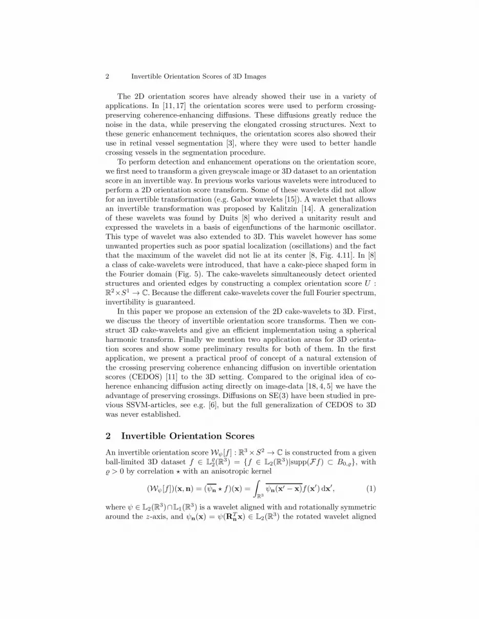
The 2D orientation scores have already showed their use in a variety ofapplications. In [11, 17] the orientation scores were used to perform crossing-preserving coherence-enhancing diffusions. These diffusions greatly reduce thenoise in the data, while preserving the elongated crossing structures. Next tothese generic enhancement techniques, the orientation scores also showed theiruse in retinal vessel segmentation [3], where they were used to better handlecrossing vessels in the segmentation procedure.
To perform detection and enhancement operations on the orientation score,we first need to transform a given greyscale image or 3D dataset to an orientationscore in an invertible way. In previous works various wavelets were introduced toperform a 2D orientation score transform. Some of these wavelets did not allowfor an invertible transformation (e.g. Gabor wavelets [15]). A wavelet that allowsan invertible transformation was proposed by Kalitzin [14]. A generalizationof these wavelets was found by Duits [8] who derived a unitarity result andexpressed the wavelets in a basis of eigenfunctions of the harmonic oscillator.This type of wavelet was also extended to 3D. This wavelet however has someunwanted properties such as poor spatial localization (oscillations) and the factthat the maximum of the wavelet did not lie at its center [8, Fig. 4.11]. In [8]a class of cake-wavelets were introduced, that have a cake-piece shaped form inthe Fourier domain (Fig. 5). The cake-wavelets simultaneously detect orientedstructures and oriented edges by constructing a complex orientation score U :R2×S1 → C. Because the different cake-wavelets cover the full Fourier spectrum,invertibility is guaranteed.
In this paper we propose an extension of the 2D cake-wavelets to 3D. First,we discuss the theory of invertible orientation score transforms. Then we con-struct 3D cake-wavelets and give an efficient implementation using a sphericalharmonic transform. Finally we mention two application areas for 3D orienta-tion scores and show some preliminary results for both of them. In the firstapplication, we present a practical proof of concept of a natural extension ofthe crossing preserving coherence enhancing diffusion on invertible orientationscores (CEDOS) [11] to the 3D setting. Compared to the original idea of co-herence enhancing diffusion acting directly on image-data [18, 4, 5] we have theadvantage of preserving crossings. Diffusions on SE(3) have been studied in pre-vious SSVM-articles, see e.g. [6], but the full generalization of CEDOS to 3Dwas never established.
2 Invertible Orientation Scores
An invertible orientation score Wψ[f ] : R3×S2 → C is constructed from a given
ball-limited 3D dataset f ∈ L2(R
3) = {f ∈ L2(R3)|supp(Ff) ⊂ B0,}, with
> 0 by correlation ⋆ with an anisotropic kernel
(Wψ [f ])(x,n) = (ψn ⋆ f)(x) =
∫
R3
ψn(x′ − x)f(x′) dx′, (1)
where ψ ∈ L2(R3)∩L1(R
3) is a wavelet aligned with and rotationally symmetricaround the z-axis, and ψn(x) = ψ(RT
nx) ∈ L2(R3) the rotated wavelet aligned

Invertible Orientation Scores of 3D Images 3
with n. HereRn is any rotation which rotates the z-axis onto n where the specificchoice of rotation does not matter because of the rotational symmetry of ψ. Theoverline denotes a complex conjugate. The exact reconstruction formula for thistransformation is
f(x) = (W−1ψ [Wψ[f ]])(x)
= F−1R3
[
M−1ψ FR3
[
x 7→
∫
S2
(ψn ⋆Wψ[f ](·,n))(x) dσ(n)
]]
(x),(2)
with FR3 the Fourier transform onR3 given by (Ff)(ω) = (2π)−3
2
∫
R3 e−iω·xf(x)dx
and ψn(x) = ψn(−x). In fact Wψ is a unitary mapping on to a reproducing ker-nel space, see App. A. The function Mψ : R3 → R+ is given by
Mψ(ω) = (2π)3
2
∫
S2
|FR3 [ψn](ω)|2dσ(n). (3)
The function Mψ quantifies the stability of the inverse transformation [8], sinceMψ(ω) specifies how well frequency component ω is preserved by the cascadeof construction and reconstruction when M−1
ψ would not be included in Eq. (2).An exact reconstruction is possible as long as
∃M>0,δ>0 0 < δ ≤Mψ(ω) ≤M <∞, for all ω = B0,. (4)
In practice it is best to aim for Mψ(ω) ≈ 1, in view of the condition number ofWψ : L2(R
3) → L2(R
3×S2) with Wψf = Wψf . Also, when Mψ(ω) = 1 we haveL2-norm preservation
‖f‖2L2(R3) = ‖Wψf‖
2L2(R3
×S2), for all f ∈ L2(R
3), (5)
and Eq. (2) simplifies to f(x) =∫
S2(ψn ⋆Wψ[f ](·,n))(x)dσ(n). We can further
simplify the reconstruction for wavelets for which (2π)3
2
∫
S2 FR3 [ψn](ω)dσ(n) ≈1, where the reconstruction formula simplifies to an integration over orientations
f(x) ≈
∫
S2
Wψf(x,n) dσ(n). (6)
Fig. 1. 2D Orientation score for an exemplary im-age. In the orientation score crossing structures aredisentangled because the different structures have adifferent orientation.
Fig. 2. A schematic view ofimage processing via invertibleorientation scores.

4 Invertible Orientation Scores of 3D Images
Fig. 3. Creating a 3D orientation score. Top: The data f is correlated with an orientedfilter ψex to detect structures aligned with the filter orientation ex. Bottom left: Thisis repeated for a discrete set of filters with different orientations. Bottom right: Thecollection of 3D datasets constructed by correlation with the different filters is anorientation score and is visualized by placing a 3D dataset on a number of orientations.
2.1 Discrete Invertible Orientation Score Transformation
In the previous section, we considered a continuous orientation score transfor-mation. In practice, we have only a finite number of orientations. To determinethis discrete set of orientations we uniformly sample the sphere using platonicsolids and/or refine this using tessellations of the platonic solids.
Assume we have a number No of orientations V = {n1,n2, ...,nNo} ⊂ S2,and define the discrete invertible orientation score Wd
ψ[f ] : R3 × V → C by
(Wdψ[f ])(x,ni) = (ψni ⋆ f)(x). (7)
The exact reconstruction formula is in the discrete setting given by
f(x) = ((Wdψ)
−1[Wdψ[f ]])(x)
= F−1R3
[
(Mdψ)
−1FR3
[
x →
No∑
i=1
(ψni ⋆Wdψ [f ](·,ni))(x)dσ(ni)
]]
(x),(8)

Invertible Orientation Scores of 3D Images 5
with dσ(ni) the discrete spherical area measure which for reasonably uniformspherical sampling can be approximated by dσ(ni) ≈
4πNo
, and
Mdψ(ω) = (2π)
3
2
No∑
i=1
|FR3 [ψni ](ω)|2dσ(ni). (9)
Again, an exact reconstruction is possible iff 0 < δ ≤Mdψ(ω) ≤M <∞.
3 3D Cake-Wavelets
A class of 2D cake-wavelets, see [8], was successfully used for the 2D orientationscore transformation. We now generalize these 2D cake-wavelets to 3D cake-wavelets. Our 3D transformation using the 3D cake-wavelets should fulfill a setof requirements, compare [11] :
1. The orientation score should be constructed for a finite number (No) oforientations.
2. The transformation should be invertible and all frequencies should be trans-ferred equally to the orientation score domain (Md
ψ ≈ 1).3. The kernel should be strongly directional.4. The kernel should be polar separable in the Fourier domain, i.e., (Fψ)(ω) =g(ρ)h(θ, φ), with ω = (ωx, ωy, ωz) = (ρ sin θ cosφ, ρ sin θ sinφ, ρ cos θ). Be-cause by definition the wavelet ψ has rotational symmetry around the z-axiswe have h(θ, φ) = h(θ).
5. The kernel should be localized in the spatial domain, since we want to pickup local oriented structures.
6. The real part of the kernel should detect oriented structures and the imag-inary part should detect oriented edges. The constructed oriented score istherefore a complex orientation score.
3.1 Construction of Line and Edge Detectors
We now discuss the procedure used to make 3D cake-wavelets. According torequirement 4 we only consider polar separable wavelets in the Fourier domain,so that (Fψ)(ω) = g(ρ)h(θ). For the radial function g(ρ) we use, as in [11],
g(ρ) = MN (ρ2t−1) = e−ρ2
t
N∑
k=0
(ρ2t−1)k
k!, (10)
which is a Gaussian function with scale parameter t multiplied by the Taylorapproximation of its reciprocal to order N to ensure a slower decay. This func-tion should go to 0 when ρ tends to the Nyquist frequency ρN . Therefore theinflection point of this function is fixed at γ ρN with 0 ≪ γ < 1 by setting
t = 2(γ ρN )2
1+2N . In practice we have = ρN , and because radial function g causes

6 Invertible Orientation Scores of 3D Images
Mdψ to become really small when coming close to the Nyquist frequency, recon-
struction Eq.(8) becomes unstable. We solve this by either using approximatereconstruction Eq.(6) or by replacing Md
ψ → max(Mdψ, ǫ), with ǫ small. Both
make the reconstruction stable at the cost of not completely reconstructing thehighest frequencies which causes some additional blurring.
We now need to find an appropriate angular part h for the cake-wavelets.First, we specify an orientation distribution A : S2 → R+, which determineswhat orientations the wavelet should measure. To satisfy requirement 3 thisfunction should be a localized spherical window, for which we propose a B-splineA(θ, φ) = Bk( θsθ ), with sθ > 0 and Bk the kth order B-spline given by
Bk(x) = (Bk−1 ∗B0)(x), B0(x) =
{
1 if− 12 < x < 1
2
0 otherwise. (11)
The parameter sθ determines the trade-off between requirements 2 and 3, wherehigher values give a more uniform Md
ψ at the cost of less directionality.First consider setting h = A so that ψ has compact support within a convex
cone in the Fourier domain. The real part of the corresponding wavelet wouldhowever be a plate detector and not a line detector (Fig. 4). The imaginary partis already an oriented edge detector, and so we set
hIm(φ) = A(θ, φ) −A(π − θ, φ+ π) = Bk(
θ
sθ
)
−Bk(
π − θ
sθ
)
, (12)
where the real part of the earlier found wavelet vanishes by anti-symmetrizationof the orientation distribution A while the imaginary part remains. As to theconstruction of hRe, there is the general observation that we detect a structurethat is perpendicular to the shape in the Fourier domain, so for line detectionwe should aim for a plane detector in the Fourier domain. To achieve this weapply the Funk transform to A, and we define
hRe(θ, φ) = FA(θ, φ) =
∫
Sp(n(θ,φ))
A(n′) ds(n′), (13)
where integration is performed over Sp(n) denoting the great circle perpendic-ular to n(θ, φ) = (sin θ cosφ, sin θ sinφ, cos θ). This transformation preserves thesymmetry of A, so we have hRe(θ, φ) = hRe(θ). Thus, we finally set
h(θ) = hRe(θ) + hIm(θ). (14)
For an overview of the transformations see Fig. 5.
3.2 Efficient Implementations Via Spherical Harmonics
In Subsection 3.1 we defined the real part and the imaginary part of the waveletsin terms of a given orientation distribution. In order to efficiently implement the

Invertible Orientation Scores of 3D Images 7
various transformations (e.g. Funk transform), and to create the various rotatedversions of the wavelet we express our orientation distribution A in a sphericalharmonic basis {Y ml } up to order L:
A(θ, φ) =L∑
l=0
l∑
m=−l
cl,mYml (θ, φ), L ∈ N. (15)
Because of the rotational symmetry around the z-axis, we only need the spher-ical harmonics with m = 0, i.e., A(θ, φ) =
∑Ll=0 cl,0Y
0l (θ, φ). For determining
the spherical harmonic coefficients we use the pseudo-inverse of the discretizedinverse spherical harmonic transform (see [9, Section 7.1]), with discrete orien-tations given by an icosahedron of tesselation order 15.
Funk Transform According to [7], the Funk transform of a spherical harmonicequals
FY ml (θ, φ) =
∫
Sp(n(θ,φ))
Y ml (n′) ds(n′) = 2πPl(0)Yml (θ, φ), (16)
with Pl(0) the Legendre polynomial of degree l evaluated at 0. We can thereforeapply the Funk transform to a function expressed in a spherical harmonic basisby a simple transformation of the coefficients cml → 2πPl(0)c
ml .
Anti-Symmetrization We have Y ml (π− θ, φ+π) = (−1)lY ml (θ, φ). We there-fore anti-symmetrize the orientation distribution Eq.(12) via cml → (1−(−1)l)cml .
Making Rotated Wavelets To make the rotated versions ψn of wavelet ψ wehave to find hn in Ψn = g(ρ)hn(θ, φ). To achieve this we use the steerability of thespherical harmonic basis. Spherical harmonics rotate according to the irreduciblerepresentations of the SO(3) group Dl
m,m′(α, β, γ) (Wigner-D functions)
RRα,β,γY ml (θ, φ) =
l∑
m′=l
Dlm,m′(α, β, γ)Y m
′
l (θ, φ). (17)
Here α, β and γ denote the Euler angles with counterclockwise rotations, i.e.,R = Rez ,αRey,βRez,γ . This gives
hn(θ, φ) = RRα,β,γh(θ, φ) =
L∑
l=0
l∑
m=−l
l∑
m′=−l
al,mDlm,m′(α, β, γ)Y m
′
l (θ, φ). (18)
Because both anti-symmetrization and Funk transform preserve the rotationalsymmetry of A, we have h(θ, φ) =
∑Ll=0 al,0Y
0l (θ, φ), and Eq. (18) reduces to
hn(θ, φ) =L∑
l=0
l∑
m′=−l
al,0Dl0,m′(0, β, γ)Y m
′
l (θ, φ). (19)

8 Invertible Orientation Scores of 3D Images
Fig. 4. When directly setting orientation distribution A as angular part of the waveleth we construct plate detectors. From left to right: Orientation distribution A, waveletin the Fourier domain, the plate detector (real part) and the edge detector (imaginarypart). Orange: Positive iso-contour. Blue: Negative iso-contour. Parameters used: L =16, sθ = 0.6, k = 2, N = 20, γ = 0.8 and evaluated on a grid of 51x51x51 pixels.
Fig. 5. Cake-Wavelets. Top: 2D cake-wavelets. From left to right: Illustration of theFourier domain coverage, the wavelet in the Fourier domain and the real and imag-inary part of the wavelet in the spatial domain. [3]. Bottom: 3D cake-wavelets.Overview of the transformations used to construct the wavelets from a given ori-entation distribution. Upper part: The wavelet according to Eq. (12). Lower part:The wavelet according to Eq. (13). IFT: Inverse Fourier Transform. Parameters used:L = 16, sθ = 1.05, k = 2, N = 20, γ = 0.8 and evaluated on a grid of 31x31x31 pixels.
Invertible Orientation Scores of 3D Images 9
4 Applications
4.1 Adaptive Crossing Preserving Flows
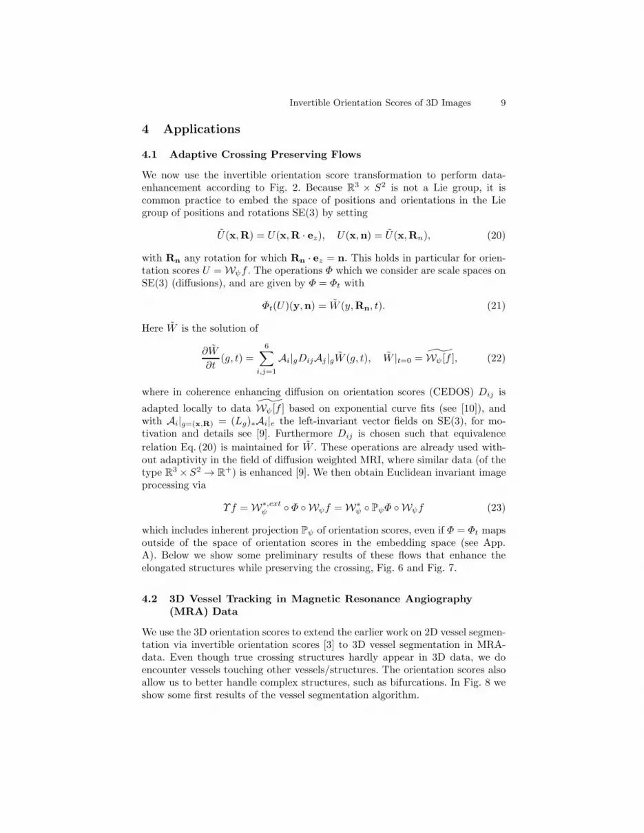
We now use the invertible orientation score transformation to perform data-enhancement according to Fig. 2. Because R3 × S2 is not a Lie group, it iscommon practice to embed the space of positions and orientations in the Liegroup of positions and rotations SE(3) by setting
U(x,R) = U(x,R · ez), U(x,n) = U(x,Rn), (20)
with Rn any rotation for which Rn · ez = n. This holds in particular for orien-tation scores U = Wψf . The operations Φ which we consider are scale spaces onSE(3) (diffusions), and are given by Φ = Φt with
Φt(U)(y,n) = W (y,Rn, t). (21)
Here W is the solution of
∂W
∂t(g, t) =
6∑
i,j=1
Ai|gDijAj |gW (g, t), W |t=0 = Wψ[f ], (22)
where in coherence enhancing diffusion on orientation scores (CEDOS) Dij is
adapted locally to data Wψ[f ] based on exponential curve fits (see [10]), andwith Ai|g=(x,R) = (Lg)∗Ai|e the left-invariant vector fields on SE(3), for mo-tivation and details see [9]. Furthermore Dij is chosen such that equivalence
relation Eq. (20) is maintained for W . These operations are already used with-out adaptivity in the field of diffusion weighted MRI, where similar data (of thetype R3 × S2 → R+) is enhanced [9]. We then obtain Euclidean invariant imageprocessing via
Υf = W∗,extψ ◦ Φ ◦Wψf = W∗
ψ ◦ PψΦ ◦Wψf (23)
which includes inherent projection Pψ of orientation scores, even if Φ = Φt mapsoutside of the space of orientation scores in the embedding space (see App.A). Below we show some preliminary results of these flows that enhance theelongated structures while preserving the crossing, Fig. 6 and Fig. 7.
4.2 3D Vessel Tracking in Magnetic Resonance Angiography(MRA) Data
We use the 3D orientation scores to extend the earlier work on 2D vessel segmen-tation via invertible orientation scores [3] to 3D vessel segmentation in MRA-data. Even though true crossing structures hardly appear in 3D data, we doencounter vessels touching other vessels/structures. The orientation scores alsoallow us to better handle complex structures, such as bifurcations. In Fig. 8 weshow some first results of the vessel segmentation algorithm.

10 Invertible Orientation Scores of 3D Images
Fig. 6. Adaptive Crossing Preserving Flows. From left to right 3D visualization ofartificial data, slice of data, slice of (data + Gaussian noise), slice of enhanced data.For the orientation score transformation we use: N0 = 42, sθ = 0.7, k = 2, N = 20, γ =0.85, L = 16 evaluated on a grid of 21x21x21 pixels. We use approximate reconstructionEq.(8), and for diffusion we set t = 10. For the choice of Dij in CEDOS, see [10].
Fig. 7. Adaptive Crossing Preserving Flows combined with soft thresholdingΦ(U)(x,n) = |U(x,n)|1.5 sgn(U(x,n)) on data containing the Adam Kiewitzc vessel.From left to right: Slice of data, data after soft thresholding, data after CEDOS, dataafter CEDOS followed by soft thresholding. For parameters see Fig.6, but now t = 5.
Fig. 8. MRA vessel segmentation via in-vertible orientation scores.
5 Conclusion
We have extended 2D cake-wavelets to 3D cake-wavelets, which can be usedfor a 3D invertible orientation score transformation. Efficient implementationfor calculating the wavelets via spherical harmonics were introduced. The devel-oped transformation allows us to consider all kinds of enhancement operationsvia orientation scores such as the adaptive crossing preserving flows which weare currently working on. Next to data-enhancement we also showed some firstresults of 3D vessel segmentation using 3D orientation scores.
Acknowledgements. We thank Dr. A.J.E.M. Janssen for advice on the presentation
of this paper. The research leading to these results has received funding from the
European Research Council under the European Community’s Seventh Framework
Programme (FP7/2007-2013) / ERC grant Lie Analysis, agr. nr. 335555.

Invertible Orientation Scores of 3D Images 11
A Invertible Orientation Scores of 3D-images and
Continuous Wavelet Theory
The continuous wavelet transform constructed by unitary irreducible represen-tations of locally compact groups was first formulated by Grossman et al. [13].Given a Hilbert space H and a unitary irreducible representation g 7→ Ug of anylocally compact group G in H , a non-zero vector ψ ∈ H is called admissible if
Cψ :=
∫
G
|(Ugψ, ψ)|2
(ψ, ψ)HdµG(g) <∞, (24)
where µG denotes the left-invariant Haar measure. Given an admissible vectorψ and a unitary representation of a locally compact group G in H , the CoherentState (CS) transformWψ : H → L2(G) is given by (Wψ [f ])(g) = (Ugψ, f)H . Wψ
is an isometric transform onto a unique closed reproducing kernel space CGKψwith Kψ(g, g
′) = 1Cψ
(Ugψ,Ug′ψ)H as an L2-subspace [1].
We distinguish between the isometric wavelet transform Wψ : L2(R
3) →L2(G) and the unitary wavelet transform Wψ : L2(R
3) → CGK . We drop theformal requirement of U being square-integrable and ψ being admissible in thesense of (24), and replace the requirement by (4), as it is not strictly needed inmany cases. This includes our case of interest G = SE(3) and its left-regularaction on L2(R
3) whereWψ gives rise to an orientation scoreWψf : R3⋊S2 → C
Wψf(x,n) = Wψf(x,Rn), (25)
with Rn any rotation mapping ez onto n and ψ symmetric around the z-axis.Here the domain is the coupled space of positions and orientations: R3 ⋊ S2 :=SE(3)/({0} × SO(2)), cf. [9].
From the general theory of reproducing kernel spaces [8, Thm 18],[2] (whereone does not even rely on the group structure), it follows that Wψ : L2(R
3) →
CR3⋊S2
K is unitary, where CR3⋊S2
K denotes the abstract complex reproducing ker-nel space consisting of functions on R3 ⋊ S2 with reproducing kernel
K(y,n)(y′,n′) = (U(y,Rn)ψ,U(y′,R
n′)ψ)L2(R3), (26)
with left-regular representation (y,R) 7→ U(y,R)ψ given by (U(y,R)ψ)(x) =
ψ(RT (x − y)). Now, as the characterization of the inner product on CR3⋊S2
K
is awkward [16], we provide a basic characterization next via the so-called Mψ
inner product. This is in line with the admissibility conditions in [12].
Theorem 1. Let ψ be such that (4) holds. Then Wψ : L2(R3) → CR
3⋊S2
K isunitary, and we have
(f, g)L2(R3) = (Wψf,Wψg)Mψ, (27)
where (Wψf,Wψg)Mψ= (TMψ
[Wψf ], TMψ[Wψg])L2(R3⋊S2)), with [TMψ
[U ]](y,n) :=
F−1
[
ω 7→ (2π)−3/4M−1/2ψ (ω)F [U(·,n)](ω)
]
(y).

12 Invertible Orientation Scores of 3D Images
Proof. We rely on [17, Thm 1], where we set H = L2(R3). The rest follows by
well posed restriction to the quotient R3 ⋊ S2.
Corollary 1. Let Mψ > 0 on R3. The space CR3⋊S2
K is a closed subspace of
Hilbert space Hψ ⊗ L2(S2), where Hψ = {f ∈ L2(R
3)| M−
1
2
ψ F [f ] ∈ L2(R3)},
and projection of embedding space onto the space of orientation scores is givenby (Pψ(U))(y,n) = (K(n,y), U)Mψ
= (WψW∗,extψ (U))(y,n), where W∗,ext
ψ is thenatural extension of the adjoint to the embedding space.
References
1. S.T. Ali. A general theorem on square-integrability: Vector coherent states. J.Math. Phys., 39(8):3954, 1998.
2. S.T. Ali, J.-P. Antoine, and J.-P. Gazeau. Coherent states, wavelets, and theirgeneralizations. Springer, 2014.
3. E. Bekkers and R. Duits. A multi-orientation analysis approach to retinal vesseltracking. JMIV, 2014.
4. B. Burgeth, S. Didas, and J. Weickert. A general structure tensor concept andcoherence-enhancing diffusion filtering for matrix fields. In Visualization and pro-cessing of tensor fields, pages 305–324. Springer,Berlin, 2009.
5. B. Burgeth, L. Pizarro, S. Didas, and J. Weickert. 3D-Coherence-enhancing dif-fusion filtering for matrix fields. In Mathematical methods for signal and imageanalysis and representation, pages 49–63. Springer London, 2012.
6. E.J. Creusen, R. Duits, and T.C.J. Dela Haije. Numerical schemes for linear andnon-linear enhancement of DW-MRI. SSVM, 1:14–25, 2012.
7. M. Descoteaux, E. Angelino, S. Fitzgibbons, and R. Deriche. Regularized, fast,and robust analytical Q-ball imaging. MRM, 58(3):497–510, September 2007.
8. R. Duits. Perceptual organization in image analysis. PhD thesis, Technische Uni-versiteit Eindhoven, 2005.
9. R. Duits and E.M. Franken. Left-invariant diffusions on the space of positionsand orientations and their application to crossing-preserving smoothing of HARDIimages. IJCV, 92(3):231–264, March 2010.
10. R. Duits, M.H.J. Janssen, J. Hannink, and G.R. Sanguinetti. Locally AdaptiveFrames in the Roto-Translation Group and their Applications in Medical Imaging.arXiv preprint: arXiv:1502.08002.
11. E.M. Franken and R. Duits. Crossing-preserving coherence-enhancing diffusion oninvertible orientation scores. IJCV, 85(3):253–278, February 2009.
12. F. Fuhr. Abstract harmonic analysis of continuous wavelet transforms. LectureNotes in Mathematics, 1863, 2005.
13. A. Grossmann, J. Morlet, and T. Paul. Transforms associated to square integrablegroup representations. I. General results. J. Math. Phys., 26(10):2473, 1985.
14. S.N. Kalitzin, B.M. ter Haar Romeny, and M.A. Viergever. Invertible aperturedorientation filters in image analysis. IJCV, 31:145–158, 1999.
15. Tai Sing Lee. Image representation using 2D Gabor wavelets. IEEE TPAMI,18(10), 1996.
16. F.J.L. Martens. Spaces of analytical functions on inductive/projective limits ofHilbert spaces. PhD thesis, Technische Universiteit Eindhoven, 1988.
17. U. Sharma and R. Duits. Left-invariant evolutions of wavelet transforms on thesimilitude group. accepted for publication ACHA, doi:10.1016/j.acha.2014.09.001.
18. J. Weickert. Coherence-enhancing diffusion filtering. IJCV, 31:111–127, 1999.
Recommended


