
OBJECTIVE
• With the increase in technology, the need for the electric energy is also increasing day by day.
• The current research areas focus on the conservation of energy in the electrical apparatus.
• Air Conditioner is one load which consumes the power in a considerable extent when compared to the other load.
ABSTRACT
• In Air-conditioner we have high in-rush current
which makes it to consume high power while running.
• The use of Variable Frequency Drive in Induction motor facilitate in consuming constant current which produces constant power consumption.
• The use of Seven-level inverter helps in producing pure sine-wave through PWM which increases the performance.
EXISTING SYSTEM
• In normal existing system when AC is switched ON motor starts with high inrush current and remains constant for certain period of time until the desired temperature is achieved and then decreases gradually.
• This process continued for every change in room temperature.
• Because of this frequent current variations Watt Hour Meter revolves faster, as a result power consumption is increased.
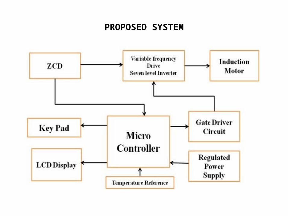
PROPOSED SYSTEM
HOW DO WE CONTROL INRUSH CURRENT?
• In order to control the in rush current in the air conditioner. here we introducing variable frequency drive with seven level inverter in single phase induction motor.
VARIABLE FREQUENCY DRIVE
• A VFD provides maximum control over the starting characteristics of the motor.
• Here frequency is varied, so the motor operates only on the right side of break down on the speed-torque curve
• The load is accelerated as slowly as possible virtually eliminating the mechanical stress.
• high speed range is achieved from zero speed to the base speed that the load needs.
• the rotor loss associated with slip is reduced considerably.
WHY WE GO FOR SEVEN-LEVEL INVERTER?
• They have nearly sinusoidal output voltage waveform.
• Output current with better Harmonic profile.• Generates lower Electromagnetic Interference(EMI).• Has less stressing of electronic components.• Lesser switching losses.• Cheaper , lighter , and more compact.
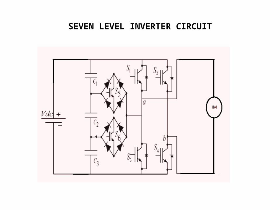
SEVEN LEVEL INVERTER CIRCUIT
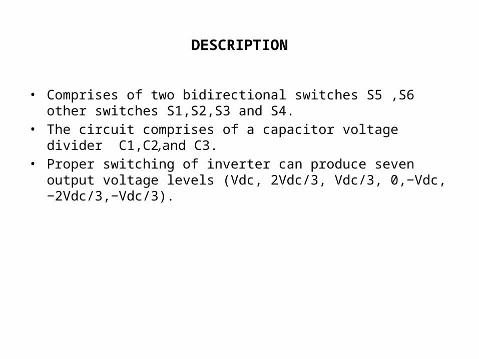
DESCRIPTION
• Comprises of two bidirectional switches S5 ,S6 other switches S1,S2,S3 and S4.
• The circuit comprises of a capacitor voltage divider C1,C2,and C3.
• Proper switching of inverter can produce seven output voltage levels (Vdc, 2Vdc/3, Vdc/3, 0,−Vdc,−2Vdc/3,−Vdc/3).
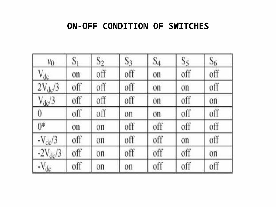
ON-OFF CONDITION OF SWITCHES
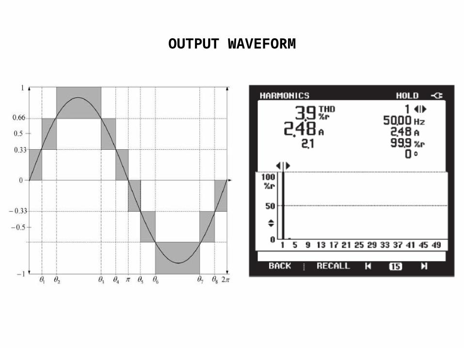
OUTPUT WAVEFORM
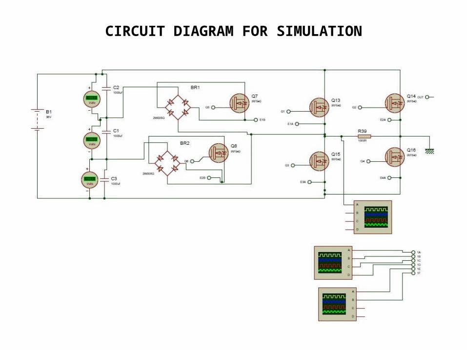
CIRCUIT DIAGRAM FOR SIMULATION
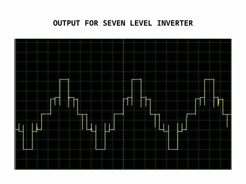
OUTPUT FOR SEVEN LEVEL INVERTER
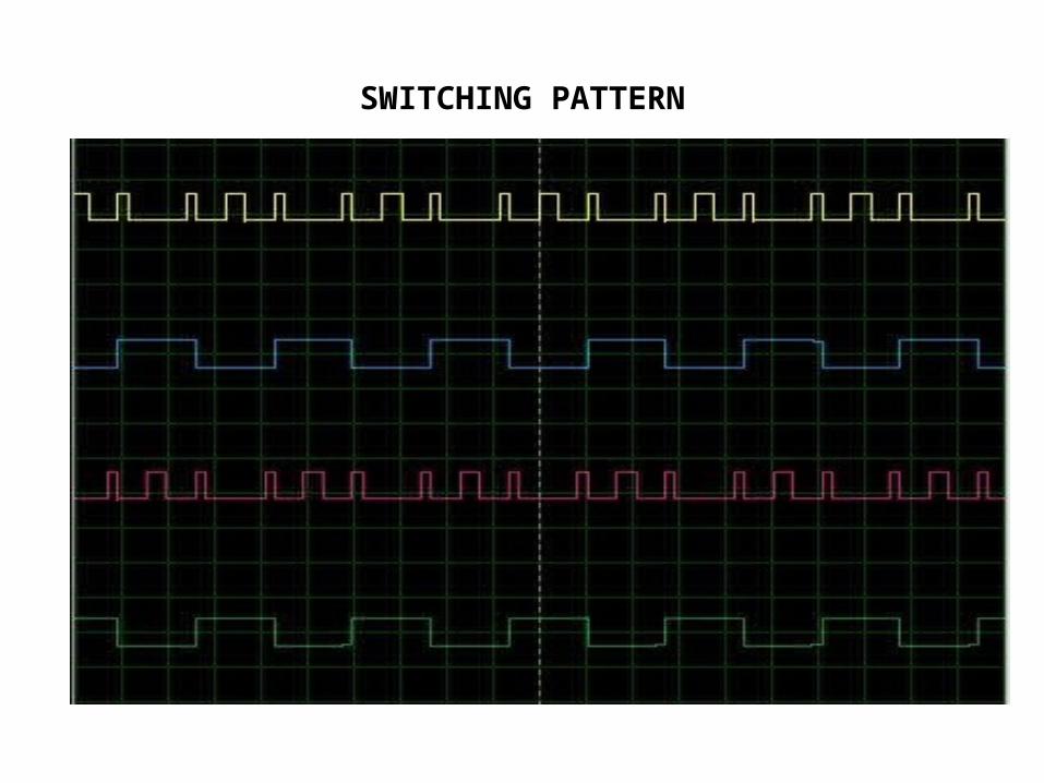
SWITCHING PATTERN
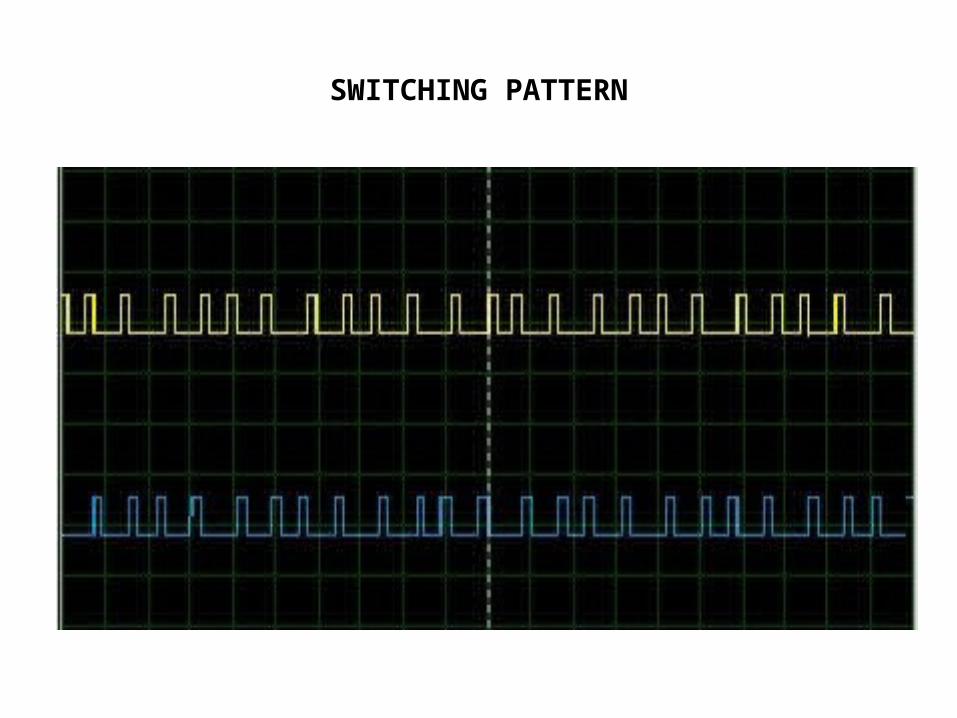
SWITCHING PATTERN
WORKING OF THE SYSTEM
• The proposed circuit consists of 230V ac supply which is given to the rectifier circuit.
• The rectifier circuit converts ac into dc, therefore regulated dc voltage is given to the seven level inverter.
• it produces pure sine wave is given to the induction motor.
• The microcontroller is used to produce the PWM sequences with references to the temperature given.
• In turn the PWM sequences only controls the output of the phase controlled rectifier and Seven- level inverter.
• Gate driver circuit is used to efficiently to drive the switches in the phase controlled rectifier and Seven-level inverter.
• LCD is used to display the room and set temperature.
ADVANTAGES OF PROPOSED SYSTEM
• Constant current maintains the power consumed in an average value.
• Once the set temperature is reached, inrush current is maintained constant.
• The use of seven level inverter helps to produce pure sine wave.
• Reduce harmonic in the system.• Performance of the system is improved.
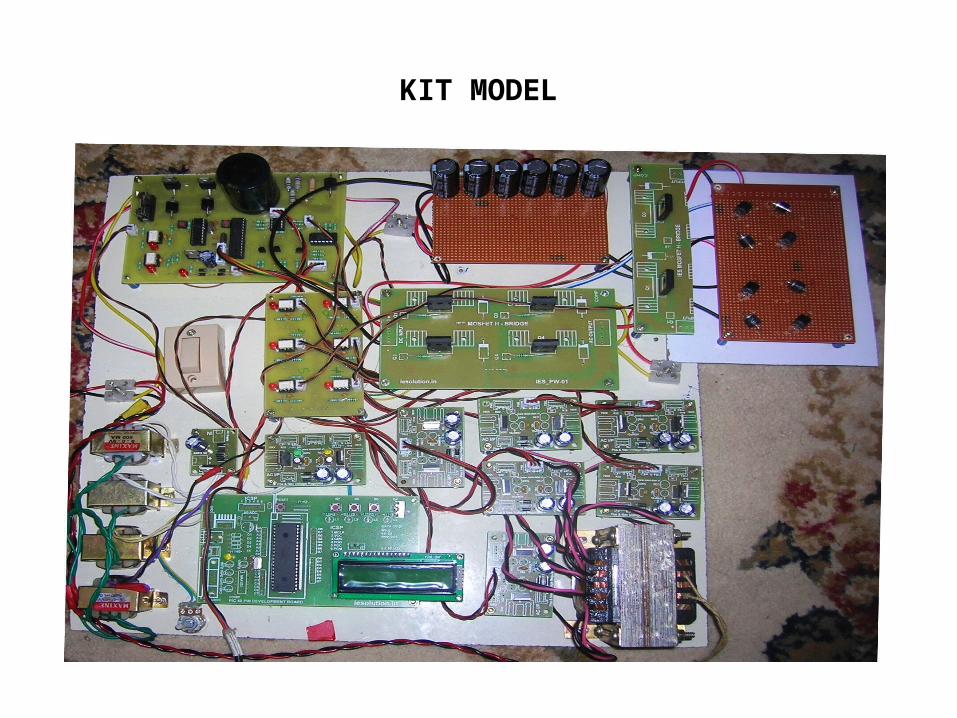
KIT MODEL
REFERENCE
• [1]. Stephanie J. Battles, “Trends in Residential Air-Conditioning Usage”.• [2]. J. Rodríguez, J. S. Lai, and F. Z. Peng, “Multilevel inverters: A survey• of topologies, controls, and applications,” IEEE Trans. Ind. Electron.,• vol. 49, no. 4, pp. 724–738, Aug. 2002.• [3]. L. Garcia Franquelo, J. Nápoles, R. C. Portillo Guisado, J. Ignacio León
and Miguel A. Aguirre, “A Flexible Selective Harmonic Mitigation Technique to Meet Grid Codes in Three-Level PWM Converters,” Trans. Industrial Electronics, Volume 54, Issue 6 Dec. 2007 p.p. 3022- 3029.
• [4]. H. S. Patel and R. G. Hoft, “Generalized techniques of harmonic elimination and voltage control in thyristor inverters—Part 1: Harmonic elimination,” IEEE Transactions on Industry Applications, vol. IA-9, May/June 1973, pp. 310–317.
• [5]. Nasrudin A. Rahim, Krismadinata Chaniago, Jeyraj Selvaraj, “Single-Phase Seven-Level Grid Connected Inverter For Photovoltaic Systems”.
• [6]. A. Shukla, A. Ghosh, and A. Joshi, “Static shunt and series compensations of an SMIB system using flying capacitor multilevel inverter,” IEEE Trans. Power Del., vol. 20, no. 4, pp. 2613–2622, Oct. 2005.
• [7].D.Kalyanakumar, Dr.V.Kirbakaran,• K.Ramash Kumar,” Hybrid Seven Level H- Bridge Inverter Based Dstatcom Control
Using Sub-Harmonic Pulse Width Modulation Technique”.• [8] S. B. Kjaer, J. K. Pedersen, and F. Blaabjerg, “A review of single-phase
grid connected inverters for photovoltaic modules,” IEEE Trans. Ind. Appl., vol. 41, no. 5, pp. 1292–1306, Sep./Oct. 2005.
• [9]. M. F. Escalante, J.-C. Vannier, and A. Arzandé, “Flying capacitor multilevel inverters and DTC motor drive applications,” IEEE Trans. Ind.,Electron., vol. 49, no. 4, pp. 809–815, Aug. 2002.
• [10]. Zhong Du, L. M. Tolbert, J. N. Chiasson and B. Ozpineci, “Reduced Switching-Frequency Active Harmonic Elimination for Multilevel Converters”, IEEE Trans. On Industrial Electronics, Volume 55, Issue
• 4, April 2008 p.p. 1761-1770.

THANK YOU
Recommended


