
Universidade do MinhoEscola de Engenharia
Novembro de 2012
Nuno Miguel Eira de Sousa
WildAniMAL MAL Interactors Model Animator
Novembro de 2012
Universidade do MinhoEscola de Engenharia
Departamento de Informática
Nuno Miguel Eira de Sousa
WildAniMAL MAL Interactors Model Animator
Dissertação de Mestrado Mestrado em Engenharia Informática
Trabalho realizado sob orientação de
Professor José Creissac Campos

i
Acknowledgements
I want to thank my thesis advisor José Creissac Campos for continuously helping me while
doing this work, by making many corrections and valuable suggestions for the implementation of
the WildAniMAL and for pointing errors and problems during the design and implementation of
the tool.
I also want to thank Manuel Sousa for providing me with a practical example of an Ipod
device model, that enabled me to show how the WildAniMAL plugin can be used. Additionally I
thank him for testing the WildAniMAL plugin, with interactor models that he developed in his own
work.
Finally, I want to thank my employer - Computer Graphics Center – for giving me a day a
week for education, during the last three years, thus enabling me to conclude this master’s
course with the current work.
ii
Abstract
The IVY Workbench is a tool for modeling and analysis of interactive systems which has been
developed at the Department of Informatics of the University of Minho (http://ivy.di.uminho.pt).
It's a platform developed in Java, using a plugins mechanism. The available plugins include a set
of editors (textual and graphical) and tools to analyse the behaviour of the models. The
experience on using the tool has demonstrated the need for a model animator which could
enable a first interactive evaluation of the models. Therefore this dissertation describes the
design and implementation of WildAniMAL - a MAL (Modal Action Logic) interactors models
animator – as a plugin for the IVY Workbench. The plugin uses the NuSMV model checker
simulations capabilities, and enables users to explore the formal models interactively.
iii
Resumo
A IVY Workbench é uma ferramenta de modelação e análise de sistemas interativos que tem
vindo a ser desenvolvida no Departamento de Informática da Universidade do Minho
(http://ivy.di.uminho.pt). Trata-se de uma plataforma desenvolvida maioritariamente em Java,
utilizando um mecanismo de plugins. Os plugins existentes incluem um conjunto de editores (em
modo texto e gráfico), e de ferramentas de análise do comportamento dos modelos. A
experiência de utilização da ferramenta tem, no entanto, demonstrado a necessidade de um
animador de modelos que permita efetuar uma primeira validação interativa dos mesmos. Sendo
assim, esta dissertação descreve o desenho e implementação do WildAniMAL – um animador de
modelos de MAL (Modal Action-Logic) Interactors – como plugin para a IVY Workbench. O plugin
usa as capacidades de simulação do model checker NuSMV, e permite aos utilizadores explorar
os modelos formais de forma interativa.
iv
Index
Acknowledgements _____________________________________________________ i
Abstract _____________________________________________________________ ii
Resumo ______________________________________________________________ iii
Index ________________________________________________________________ iv
Figures ______________________________________________________________ vii
Acronyms ____________________________________________________________ ix
Chapter 1 – Introduction ________________________________________________ 1
1.1. Goal __________________________________________________________________ 2
1.2. Structure Of The Document _______________________________________________ 2
Chapter 2 – Theoretical Background _______________________________________ 3
2.1. Model Checking _________________________________________________________ 3
2.2. NUSMV _______________________________________________________________ 5
2.3. Finite State Machine _____________________________________________________ 7
2.4. Binary Decision Diagrams _________________________________________________ 9
2.5. MAL Interactors ________________________________________________________ 11
2.6. SMV Language _________________________________________________________ 12
2.7. CTL __________________________________________________________________ 13
2.8. Conclusion ____________________________________________________________ 14
Chapter 3 – IVY Workbench _____________________________________________ 16
3.1. The IVY Workbench Approach ____________________________________________ 16
3.1.1 Creating Models ____________________________________________________________ 17
v
3.1.2 Expressing Properties ________________________________________________________ 19
3.1.3 Verification ________________________________________________________________ 20
3.1.4 Trace Analysis ______________________________________________________________ 21
3.2. How To Create An IVY Workbench Plugin ___________________________________ 25
3.3. Conclusion ____________________________________________________________ 28
Chapter 4 – Related Work ______________________________________________ 29
4.1. CTTE _________________________________________________________________ 29
4.2. AniMAL _______________________________________________________________ 32
4.3. Conclusion ____________________________________________________________ 34
Chapter 5 – WildAniMAL Implementation Approaches _______________________ 35
5.1. Implementation Approaches _____________________________________________ 35
5.1.1 Generating a Finite State Machine _____________________________________________ 36
5.1.2 NuSMV Binary Decision Diagrams ______________________________________________ 37
5.1.3 NuSMV Simulation Capabilities ________________________________________________ 37
5.2. NuSMV Interactive Shell _________________________________________________ 39
5.2.1 Model Reading And Building __________________________________________________ 39
5.2.2 Simulation Commands _______________________________________________________ 40
5.2.3 Simulation Example _________________________________________________________ 41
5.3. Conclusion ____________________________________________________________ 46
Chapter 6 – WildAniMAL Implementation _________________________________ 47
6.1. WildAniMAL’s Architecture ______________________________________________ 47
6.2. WildAniMAL’s Source Code Description ____________________________________ 53
6.2.1 Animator Package __________________________________________________________ 53
6.2.2 Constraints Package _________________________________________________________ 62
6.2.3 NuSMV Package ____________________________________________________________ 64
6.3. Conclusion ____________________________________________________________ 68
Chapter 7 – Using WildAniMAL __________________________________________ 70
7.1. WildAniMAL’s Usage Example __________________________________________________ 70
7.2. Conclusion _________________________________________________________________ 80
Chapter 8 – Conclusions and Future Work _________________________________ 81

vi
8.1. Goal _________________________________________________________________ 81
8.2. Results _______________________________________________________________ 81
8.3. Future Work ___________________________________________________________ 83
References __________________________________________________________ 84
Appendix I – Build.xml _________________________________________________ 87
Appendix II – Ipod interactors model _____________________________________ 93
Fig
FIGURE
FIGURE
FIGURE
FIGURE
FIGURE
FIGURE
FIGURE
FIGURE
FIGURE
FIGURE
FIGURE
FIGURE
FIGURE
FIGURE
FIGURE
FIGURE
FIGURE
FIGURE
FIGURE
FIGURE
FIGURE
FIGURE
FIGURE
FIGURE
FIGURE
FIGURE
FIGURE
FIGURE
FIGURE
gures
E 1 MODEL CHEC
E 2 A GRAPH OF
E 3 FSM EXAMP
E 4 DIAGRAM FO
E 5 ROBDD FOR
E 6 IVY WORKB
E 7 MODEL EDIT
E 8 MODEL EDIT
E 9 PROPERTIES
E 10 BEHAVIOUR
E 11 TRACE ANA
E 12 TREE VISUA
E 13 STATE BASE
E 14 LOGICAL ST
E 15 TABULAR V
E 16 ACTIVITY D
E 17 IVY WORK
E 18 CTTE TOOL
E 19 AN EXAMPL
E 20 OVERVIEW
E 21 A SIMPLE C
E 22 THERMOM
E 23 PROTOTYPE
E 24 NUSMV SI
E 25 INTERACTO
E 26 STATE DIAG
E 27 NUSMV SP
E 28 THE RESULT
E 29 THE RESULT
CKING SYSTEM, A
AN EXTREMELY B
PLE OF A PARSER
OR ,
R (X1⇔Y1)^(X2
ENCH ARCHITECT
TOR PLUGIN (GRA
TOR PLUGIN (TEX
EDITOR. ..........
R TRACE. ..........
ALYSIS MECHANIS
AL REPRESENTATI
ED VISUAL REPRE
TATES VISUAL RE
VISUAL REPRESEN
DIAGRAM VISUAL
BENCH PLUGINS
L, TAKEN FROM [
LE OF A TASK MO
OF THE CTT NO
CONCURTASKTRE
ETER, TAKEN FRO
E OF AN AIR CON
MULATION EXAM
ORS MODEL OF A
GRAM OF GATE M
PECIFICATION OF
T OF PICK_STATE
T OF SIMULATE –
ADAPTED FROM [
BASIC PROCESS IN
RECOGNIZING T
TAKEN FROM [1
2⇔Y2) WITH VA
TURE. ..............
APHICAL). ........
XT). .................
......................
......................
SMS (MARKERS).
ON. ................
ESENTATION. .....
PRESENTATION. .
TATION. ..........
REPRESENTATIO
FRAMEWORK. .
[25]. ..............
ODEL, TAKEN FRO
TATION, TAKEN F
EE TASK MODEL S
OM [29]. .........
DITION CONTRO
MPLE. ..............
GARAGE GATE. ..
MODEL. ............
F THE GATE MOD
E –I –A COMMAN
–I –A –K 1 COMM
vii
[9], WITH THE IV
N A FINITE STATE
THE WORLD "NIC
16]. ................
ARIABLE ORDERIN
......................
......................
......................
......................
......................
. ....................
......................
......................
......................
......................
ON. .................
......................
......................
OM [25]. .........
FROM [28]. .....
SIMULATOR, TAK
......................
L PANEL, TAKEN
......................
......................
......................
EL. .................
ND. .................
MAND. ............
VY WORKBENCH
E MACHINE. ......
E". .................
.....................
NG X1<X2<Y1<Y
.....................
.....................
.....................
.....................
.....................
.....................
.....................
.....................
.....................
.....................
.....................
.....................
.....................
.....................
.....................
KEN FROM [28].
.....................
FROM [29]. ....
.....................
.....................
.....................
.....................
.....................
.....................
APPROACH. .....
......................
......................
......................
Y2, TAKEN FROM
......................
......................
......................
......................
......................
......................
......................
......................
......................
......................
......................
......................
......................
......................
......................
......................
......................
......................
......................
......................
......................
......................
......................
......................
......................
......................
......................
......................
M [17]. ............
......................
......................
......................
......................
......................
......................
......................
......................
......................
......................
......................
......................
......................
......................
......................
......................
......................
......................
......................
......................
......................
......................
......................
......................
........ 4
........ 8
........ 9
........ 9
...... 10
...... 17
...... 18
...... 18
...... 19
...... 21
...... 21
...... 22
...... 23
...... 23
...... 24
...... 24
...... 25
...... 30
...... 30
...... 31
...... 32
...... 33
...... 34
...... 38
...... 42
...... 42
...... 43
...... 44
...... 44
viii
FIGURE 30 THE RESULT OF CHOOSING STATE 0. ..................................................................................................... 45
FIGURE 31 STATE BASED DIAGRAM SHOWING THE SIMULATION PATH. ....................................................................... 45
FIGURE 32 WILDANIMAL PLUGIN ARCHITECTURE AS A PACKAGE DIAGRAM. ............................................................... 48
FIGURE 33 MAIN PACKAGE CLASS DIAGRAM. ........................................................................................................ 49
FIGURE 34 NUSMV PACKAGE CLASS DIAGRAM. .................................................................................................... 50
FIGURE 35 CONSTRAINTS PACKAGE CLASS DIAGRAM. .............................................................................................. 51
FIGURE 36 TRACES PACKAGE CLASS DIAGRAM. ...................................................................................................... 52
FIGURE 37 GRAPHICAL USER INTERFACE IMPLEMENTED BY GUI CLASS. ...................................................................... 55
FIGURE 38 IPOD MODEL CREATION WITH MODEL EDITOR PLUGIN. ............................................................................ 71
FIGURE 39 IPOD INTERACTOR MODEL COMPILATION WITH PROPERTIES EDITOR PLUGIN. ................................................ 72
FIGURE 40 RESULT OF PRESSING “GET INITIAL STATE” IN WILDANIMAL. .................................................................. 73
FIGURE 41 SIMULATION REACHED A “TOO MANY STATES” SITUATION. ...................................................................... 74
FIGURE 42 STATE BASED REPRESENTATION OF THE TRACE CREATED IN THE SIMULATION. ............................................... 75
FIGURE 43 TABULAR REPRESENTATION OF THE TRACE CREATED IN THE SIMULATION. ..................................................... 75
FIGURE 44 LOG REPRESENTATION OF THE SIMULATION. .......................................................................................... 76
FIGURE 45 CONSTRAINTS INSERTION. .................................................................................................................. 77
FIGURE 46 RESULT OF APPLICATION OF THE CONSTRAINTS SENT. ............................................................................... 77
FIGURE 47 STATE BASED REPRESENTATION OF A TRACE ORIGINATED IN A SIMULATION. ................................................. 79
ix
Acronyms
BDD Binary Decision Diagrams
CMU Carnegie Mellon University
CTEE ConcurTaskTrees Environment
CTL Computacional Tree Logic
CTT ConcurTaskTrees
CUDD CU Decision Diagram Package
ETC Enabled Task Collection
FSM Finite State Machine
IRST Istituto per la Ricerca Scientica e Tecnologica
IVY Interactors VerifYier
LTL Linear Temporal Logic
MAL Modal-Action Logic
RBC Reduced Boolean Circuit
SAT Satisfiability Problem
SMV Symbolic Model Verifier
UI User Interface
UML Unified Modeling Language
1
Chapter 1 – Introduction
Developing complex systems will always be a complex endeavour. When developing
interactive devices, we are faced with the challenge of understanding not only how the device
must be built, but also how it will interact with its users, and how both device and users (the
interactive system) will influence each other.
Formal (mathematically rigorous) methods have long been proposed as a means of dealing
with complexity. When considering the behaviour of systems, model checking [1] has gained
particular popularity. Several approaches to the application of model checking to reason about
interactive systems (or interactive devices) have been put forward over the last seventeen years.
See, for example, the work in [2], [3], or [4]. However, applying model checking is in itself a
complex task. Both systems and Properties to be verified must be expressed in appropriate
logics. In order to make model checking of interactive systems feasible, we must provide tools
that help in the modelling and analysis process.
The IVY Workbench tool supports the modelling and verification approach put forward in [3].
The main goal of the tool is the detection of potential usability problems early in development of
any interactive system. For that, the tool enables the automated inspection of interactive systems
models. The tool supports a modelling and analysis cycle where the models are obtained by a
modelling process based on an editor, the properties are expressed using a dedicated properties
editor, the analysis is performed using the SMV model checker [5] (more specifically NuSMV [6],
a reimplementation of that tool, that is available at http://nusmv.fbk.eu), and the counter-
examples visualized using a dedicated traces visualiser. The tool has been applied to the analysis
of different devices, from control panels in the automotive industry [7], to medical devices such
as infusion pumps [8]. While model checking through NuSMV, enables a thorough analysis of all
possible behaviours of a model, the continuous use of the tool has highlighted the need for a
2
lighter weight approach to the initial validation of the models. In fact, experience has shown that
before the analysis of a given design begins, there usually happens a first phase of model
validation, where the interest is in establishing that the model behaves as expected. Experience
also shows that doing this through model checking becomes cumbersome. What is needed is the
possibility of interactively explore the behaviour of the models: manually trigger events and
observe how the system evolves. Hence the need was identified of developing a component
aiming at assisting the modelling and analysis process, by providing functionalities to simulate
and validate the model being created: WildAniMAL (Watch It vaLiDation Animator for MAL).
1.1. Goal
The goal of this work is to develop a new plugin – WildAniMAL – for the IVY Workbench tool,
supporting the animation of MAL interactor models. In order to implement it, three possibilities
will be studied:
a) representing a MAL interactors model as a Finite State Machine (FSM) and use that to
drive the animation;
b) use the BDD (Binary Decision Diagrams) representation of the MAL interactors model,
created by the NuSMV model checker to perform the animation;
c) use the NuSMV model checker simulations commands, available on its interactive mode,
to perform the animation.
1.2. Structure Of The Document
This first chapter has presented the motivation and goals of the work. The remaining of the
dissertation is structured as follows. Chapter 2 introduces the main concepts needed to
understand the work. Chapter 3 introduces the IVY workbench tool. Chapter 4 describes some
related tools. Chapter 5 discusses alternatives to implementing the WildAniMAL plugin, and
chapter 6 the implementation produced. Chapter 7 describes an usage example. The dissertation
ends, in Chapter 8, with a discussion of results and ideas for further work.
3
Chapter 2 – Theoretical
Background
This chapter presents the theoretical background needed to explain the WildAniMAL
implementation and all the concepts related to its use, and the use of the IVY Workbench, in
which it will be integrated.
Section 2.1 presents Model Checking the technology used by the IVY Workbench to perform
verification. Section 2.2 presents NuSMV that is the model checker used in IVY Workbench, and
therefore also used to implement WildAniMAL’s functionalities. Section 2.3 presents Finite State
Machines, a mathematical model of computation, and also a state’s representation, widely used
to describe computer programs. Section 2.4 presents Binary Decision Diagrams, the data
structure used to represent a Boolean function. Two representations used in NuSMV as internal
representations. Section 2.5 presents the MAL interactors language used to create models that
will be simulate in the WildAniMAL plugin, and Section 2.6 presents the SMV language, the
language into which MAL interactors models are compiled for verification and (now) animation.
Finally, CTL is presented, that is a temporal logic that is used to express properties over the
interactors model. These properties can be verified using NuSMV model checker.
2.1. Model Checking
Clarke [9] formally describes the Model Checking problem as:
Let M be a Kripke structure (i.e., state-transition graph). Let f be a formula of
temporal logic (i.e., the specification). Find all states s of M such that M; s |= f.
T
satisf
T
Figure
F
mode
Sectio
That is, given
fy the specific
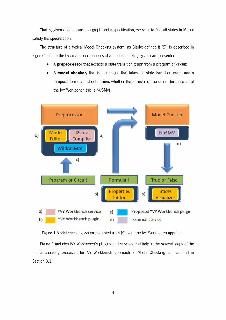
The structure
e 1. There th
A pre
A mo
temp
the IV
Figure 1 Mo
Figure 1 inclu
el checking
on 3.1.
n a state-tran
cation.
e of a typica
he two mains
eprocessor
odel check
poral formula
VY Workbenc
odel checking
udes IVY Wo
process. Th
sition graph
l Model Che
s components
r that extracts
ker, that is,
a and determ
ch this is NuS
g system, ada
rkbench’s pl
he IVY Work
4
and a specif
ecking system
s of a model
s a state tran
an engine th
mines whethe
SMV).
apted from [9
ugins and se
bench appro
fication, we w
m, as Clarke
checking sy
nsition graph
hat takes the
er the formul
9], with the I
ervices that h
oach to Mod
want to find a
defined it [9
stem are pre
from a prog
e state trans
a is true or n
VY Workbenc
help in the se
del Checking
all states in M
9], is describ
esented:
gram or circu
sition graph
not (in the c
ch approach
everal steps
g is present
M that
bed in
it;
and a
ase of
.
of the
ted in
5
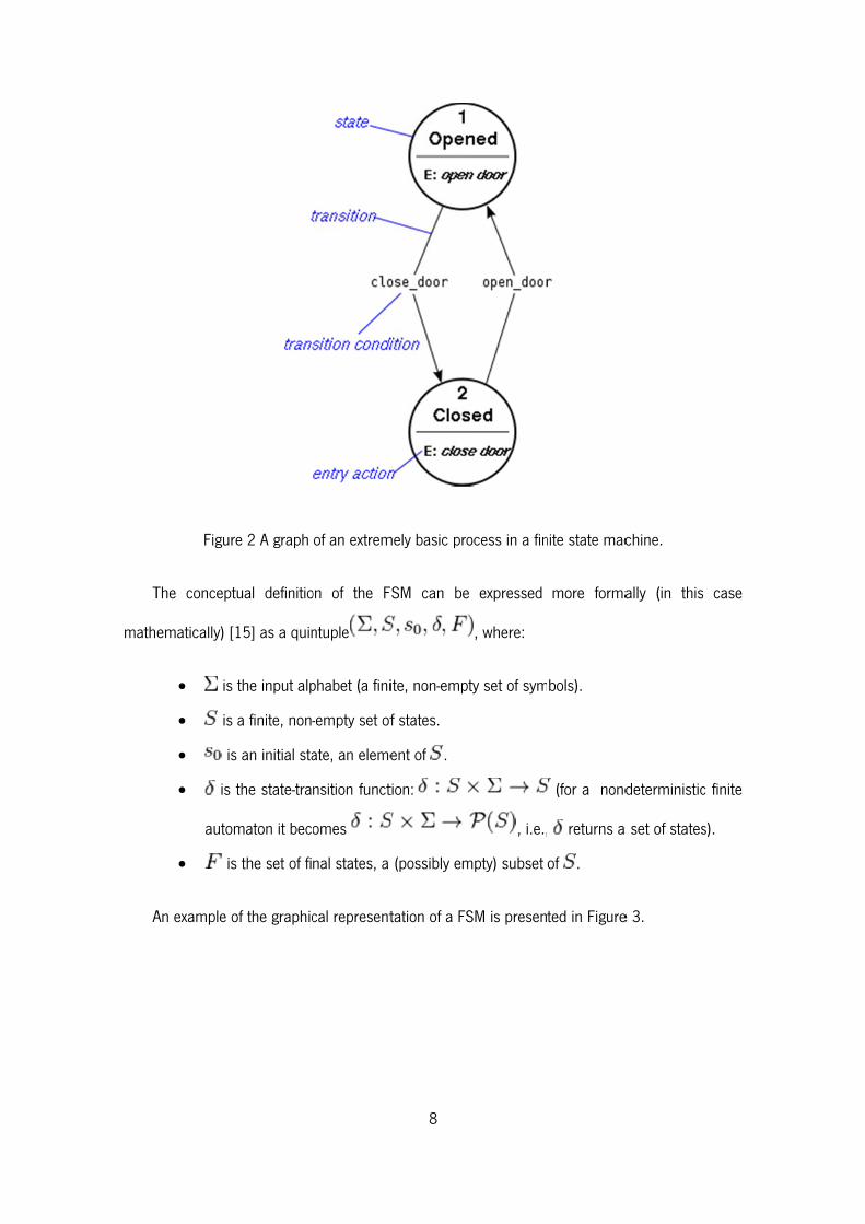
There are other verification techniques other than Model Checking, such as Automated
Theorem proving or Proof Checking. Therefore is useful to present the advantages that Model
Checking has when compared to them. Some of these advantages are:
It provides counterexamples. In a model checker, a counterexample (an execution
trace) is produced to show why a specification does not hold. This is a great
advantage because counterexamples are great to debug complex systems. Some
people use Model Checking just for this feature;
It uses Temporal Logics that can easily express properties for proving over the
behaviour of modelled systems. One example of these Temporal Logics is CTL,
which is described in Section 2.7. CTL is used in the IVY Workbench tool.
In the opposite side there are also some disadvantages and one of the major ones is State
Explosion. In [3] the authors describe this problem as related to the size of the finite state
machine (this concept will be described in Section 2.3) needed to specify a given system. A
specification can generate state spaces so immense that it becomes impossible to analyse the
entire state space. To attenuate this problem, Symbolic Model Checking was developed. When
the traversal of the state space is done considering large sets of states at a time, and is based on
representations of states sets and transition relations as formulas, binary decision diagrams or
other related data structures, the model-checking method is considered Symbolic. With that
technique state spaces as large as 1020 may be analysed [10]. NuSMV is a model checker that
uses that method and will be described in the following Section.
2.2. NUSMV
NUSMV is a symbolic model checker that was first presented in [6] and [11]. It is the result
of a joint project between Carnegie Mellon University (CMU) and Istituto per la Ricerca Scientica e
Tecnologica (IRST) and is the final product of an effort of reengineering, reimplementation and
extension of CMU SMV, the original BDD-based model checker developed at CMU [5].
Over the years NuSMV had several contributions that improved it with more functionality, as
can be seen in its official site1. Now it combines a BDD-based model checking component that
1 http://nusmv.fbk.eu/ Last visited in 10-28-2012.
6
exploits the CUDD2 library developed by Fabio Somenzi at Colorado University, and a SAT-based
model checking component that includes an RBC-based Bounded Model Checker, which can be
connected to the Minisat SAT Solver3 and/or to the ZChaff SAT Solver4. The University of Genova
has contributed SIM, a state-of-the-art SAT solver used until version 2.5.0, and the RBC package
used in the Bounded Model Checking algorithms.
In [12] we can see the current main functionalities that it provides:
allows for the representation of synchronous and asynchronous finite state systems;
allows for the analysis of specifications expressed in Computational Tree Logic (CTL)
and Linear Temporal Logic (LTL), using BDD-based and SAT-based model checking
techniques.
provides Heuristics for achieving efficiency and partially controlling the state
explosion;
provides a textual (interactive mode) and a batch mode interface to interact with its
users.
NuSMV, as a model checker, can verify properties of a finite system and for that to be
possible a model of the system (in fact, in terms of model checking, a specification of the
system) has to be created. NuSMV uses the SMV Language (see Section 2.7) to define the
specifications used as input. In [13] it is described how this language can be used to allow for the
description of Finite State Machines (FSM) which can be completely synchronous or completely
asynchronous. More specifically the SMV Language is used to describe the transition relation of
the FSM that describes the valid evolutions of the state of the FSM.
In the IVY Workbench, that model is created in the MAL Interactors language (see Section
2.5), that is easier to learn and can be compiled (using the IVY Workbench i2smv service) into a
SMV specification. After having a SMV specification, NuSMV can verify that a model satisfies a set
of desired properties specified by the user. For that, it uses two Temporal Logics: CTL or LTL.
One useful feature that NuSMV has is that it provides the user with the possibility of
simulating a NuSMV specification. As stated in [13], this way the user can explore the possible
2 http://vlsi.colorado.edu/~fabio/CUDD/ Last visited in 10-28-2012. 3 http://minisat.se/ Last visited in 10-28-2012. 4 http://www.princeton.edu/~chaff/zchaff.html Last visited in 10-28-2012.
7
executions (traces) of the NUSMV specification. In this way, the user can check the specification
correctness, before actually engaging in the verification of properties. An example of the use of
this feature can be seen in Section 5.2.3.
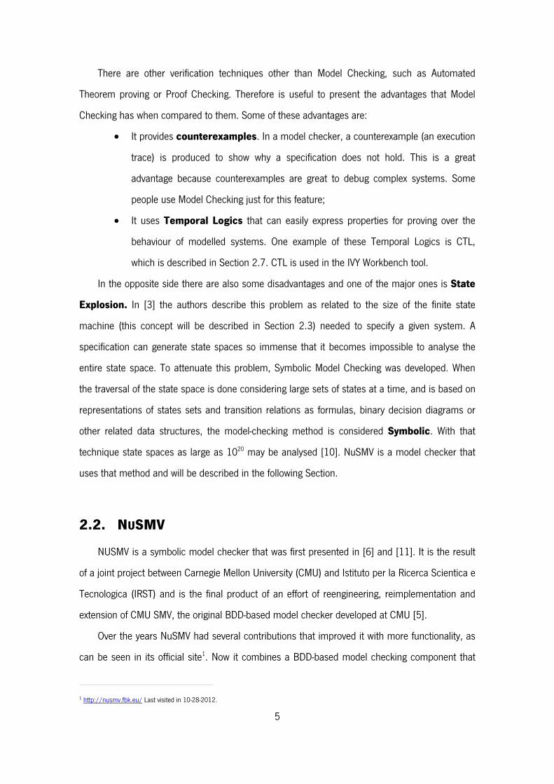
2.3. Finite State Machine
When modelling the behaviour of systems, State Machines are one of the oldest and best
ways known. They define the state of a system at a particular point in time and characterize its
behaviour based on that state.
If we want to model and design software systems we can apply the State Machines method
by identifying the states the system can be in, which inputs or events trigger state transitions, and
what system behaviour is expected in each state. The execution of the software can be seen as a
sequence of transitions that move the system through its various states.
The characteristics of a system that enable it to be modelled as a Finite State Machine (FSM)
are [14]:
The system must be specifiable as a finite set of states;
The system must have a finite set of inputs and/or events that can trigger
transitions between states;
The behaviour of the system at a given point in time depends upon the current state
and the input or event that occur at that time only;
For each state the system may be in, behaviour is defined for each possible input
or event;
The system has a particular initial state.
Figure 2 illustrates the main concepts that a Finite State Machine is known for.
T
math
A
Figur
The concept
ematically) [
is
is
is
is
autom
is
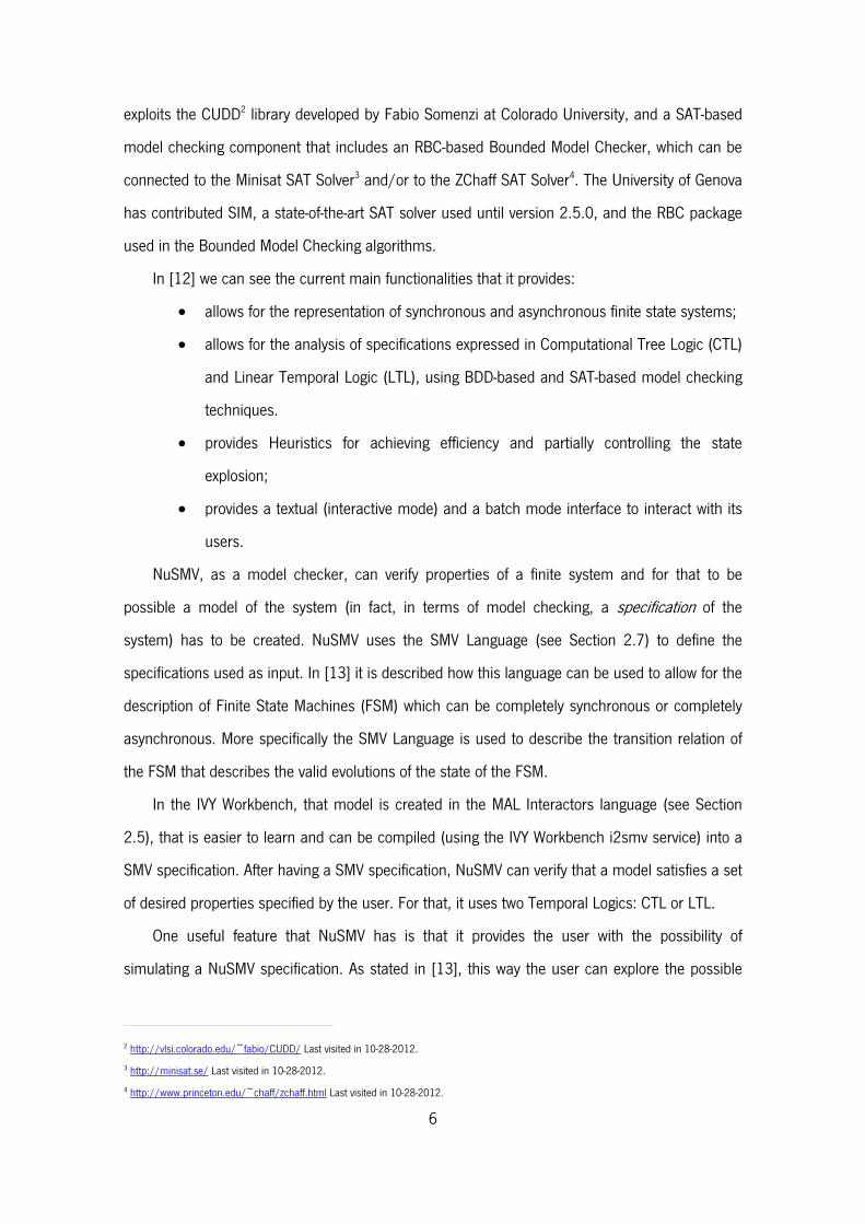
An example o
re 2 A graph
tual definitio
15] as a quin
the input alp
a finite, non-
s an initial sta
the state-tra
maton it beco
s the set of fi
of the graphic
of an extrem
on of the F
ntuple
phabet (a fini
-empty set of
ate, an eleme
nsition funct
omes
nal states, a
cal represent
8
mely basic pro
SM can be
ite, non-empt
f states.
ent of .
tion:
(possibly em
tation of a FS
ocess in a fin
expressed
, where:
ty set of sym
, i.e.,
mpty) subset
SM is presen
nite state mac
more forma
bols).
(for a nond
returns a
of .
ted in Figure
chine.
ally (in this
deterministic
set of states
e 3.
case
c finite
s).
2.4
B
repre
repre
A
acycl
F
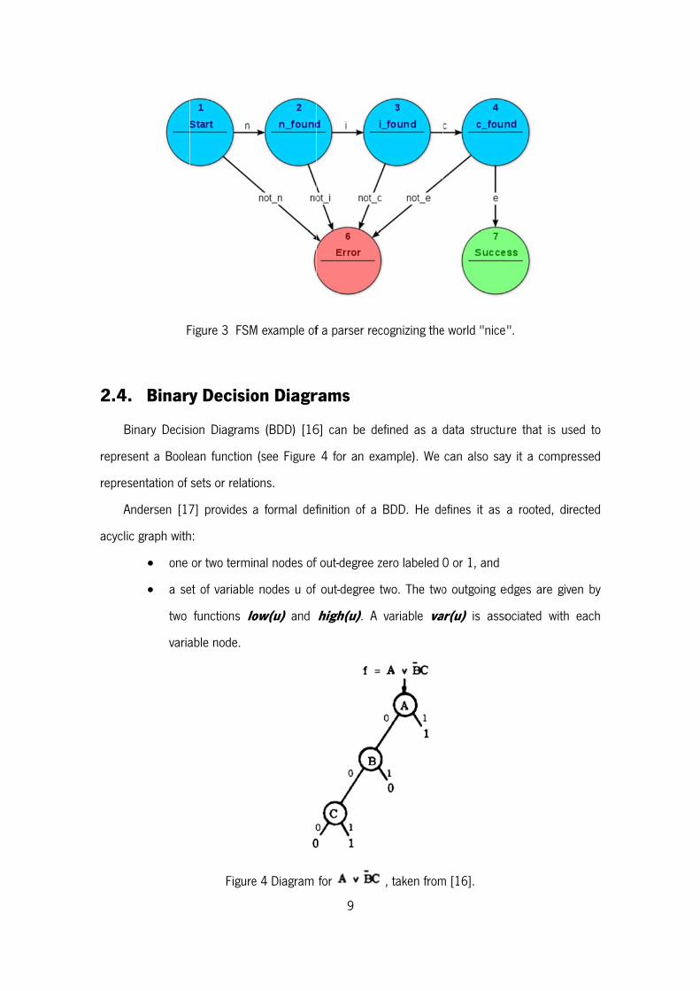
4. Binary
Binary Decis
esent a Boole
esentation of
Andersen [17
ic graph with
one
a se
two
varia
Figure 3 FSM
y Decisio
ion Diagram
ean function
sets or relati
7] provides
h:
or two termi
et of variable
functions lo
able node.
Figure
M example of
on Diagr
s (BDD) [16
(see Figure
ons.
a formal def
nal nodes of
e nodes u of
ow(u) and
e 4 Diagram
9
f a parser rec
rams
6] can be de
4 for an ex
finition of a
f out-degree z
out-degree
high(u). A
for
cognizing the
efined as a
xample). We
BDD. He de
zero labeled
two. The two
variable va
, taken from
e world "nice
data structu
can also say
efines it as
0 or 1, and
o outgoing e
ar(u) is asso
m [16].
".
re that is us
y it a compr
a rooted, di
edges are giv
ociated with
sed to
ressed
rected
ven by
each
W
define
linear
A
Fig
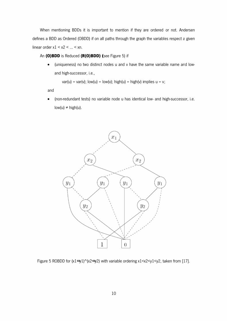
When mentio
es a BDD as
r order x1 < x
An (O)BDD i
(uniq
and
and
(non
low(u
gure 5 ROBD
oning BDDs
Ordered (OB
x2 < … < xn.
is Reduced (
queness) no
high-success
var(u) = var(
n-redundant t
u) ≠ high(u).
DD for (x1⇔y1
it is import
BDD) if on al
R(O)BDD) (
two distinct
sor, i.e.,
(v); low(u) = l
tests) no vari
1)^(x2⇔y2) w
10
tant to ment
ll paths throu
(see Figure 5
nodes u and
low(v); high(u
iable node u
with variable
tion if they a
ugh the grap
5) if
d v have the
u) = high(v) i
has identica
ordering x1<
are ordered
h the variabl
same variab
mplies u = v
al low- and h
<x2<y1<y2, ta
or not. And
les respect a
ble name an
v;
high-successo
aken from [1
dersen
given
d low-
or, i.e.
17].
11
In most cases, when BDDs are referred to, it is implied that we are referring to Reduced
Ordered Binary Decision Diagrams.
Bryant [18] studied the BDD potential for being used to create efficient algorithms. He
introduced a fixed variable ordering (for canonical representation) and shared sub-graphs (for
compression). After that he extended the sharing concept to several BDDs, i.e. one sub-graph by
several BDDs and, doing that, he defined the data structure Shared Reduced Ordered Binary
Decision Diagram. That new structure is normally what people have in mind when mentioning
BDDs.
The NuSMV model checker uses BDDs, because they are very efficient and can be used to
create efficient algorithms, as shown in [18]. The efficiency of algorithms is important in the area
of Model Checking, and because of that the use of BDDs by NuSMV was an obvious choice.
2.5. MAL Interactors
MAL interactors follow from the notion of interactor put forward in [19]: an object with the
capability of rendering part of its state to some presentation medium. A MAL interactor is defined
by:
a set of typed attributes that define the interactor's state;
a set of actions that define operations on the set of attributes;
a set of axioms written in MAL [20] that define the semantics of the actions in terms of
their effect on interactor's state.
The mapping of the interactor's state to the presentation medium is accomplished by
decorating the attributes with modality annotations. MAL axioms define how the interactor's state
changes in response to actions being executed on the interactor. In [3] the axioms are defined in
five types. In the syntax of each type, the notation prop(expr1,..,exprn) is used to denote a formula
on expressions expr1 to exprn using propositional operators only. Also, the names a1 to an
denote interactor attributes and ac denotes an action. The five types are:
Invariants – these are formulae that do not involve any kind of action or (reference)
event (i.e. simple propositional formulae). They must hold for all states of the interactor;
o Syntax: prop(a1,..,an).
12
Initialisation axioms – these are formulae that involve the reference event ([]). They
define the initial state of the interactor;
o Syntax: [] prop(a1,..,an).
Modal axioms – these are formulae involving the modal operator. They define the
effect of actions in the state of the interactor;
o Syntax: prop([ac] a1,..,[ac]ag, ah,..,an).
Permission axioms – these are deontic formulae involving the use of per. They
define specific conditions for actions to be permitted to happen;
o Syntax: per(ac) → prop(a1,..,an)
Obligation axioms – these are deontic formulae involving the use of obl. They define
the conditions under which actions become obligatory.
o Syntax: prop(a1,..,an) → obl(ac)
2.6. SMV Language
The SMV language will be used as an intermediate representation of the MAL interactors
model. Therefore an explanation of the main aspects of the SMV language is needed. The
following description of the language is adapted from [3] and [12].
An SMV specification is defined as a collection of modules. Each module defines a Finite
State Machine (FSM) and consists of a number of state variables, input variables and frozen
variables, a set of rules that define how the module makes a transition from one state to the next
and Fairness conditions that describe constraints on the valid paths of the execution of the FSM.
A state model is defined as an assignment of values to a set of state and frozen variables.
State variables can change their values throughout the evolution of the FSM. Frozen variables
cannot, as they retain their initial value, and that is what distinguishes the two. Input variables
are used to label transitions of the Finite State Machine.
An example of an SMV specification is the following:
MODULE main -- attributes VAR currentSong: 0..5;
13
lastDisplay: {MainMenu, Music, Playing, OFF}; playbackState: {playing, paused, stoped}; display: {MainMenu, Music, Playing, OFF}; -- actions VAR action: {pause, longPlay, play, nil}; -- axioms INIT display = OFF INIT playbackState = stoped INIT lastDisplay = MainMenu INIT currentSong = 0 TRANS next(action)=pause -> playbackState = playing TRANS next(action)=play -> playbackState = stoped | playbackState = paused INIT action = nil
To create a SMV specification the following list of declarations is used:
VAR allows the declaration of state variables;
IVAR allows the declaration of input variables;
FROZENVAR allows the declaration of frozen variables;
INIT allows the definition of the initial states of the model;
INVAR allows the specification of invariants over the state.
TRANS allows the definition of the behaviour of the model. In these definitions,
the operator next is used to refer to the next state;
FAIRNESS allows the declaration of fairness constraints, that is, conditions that
must hold infinitely often over the execution paths of the model.
2.7. CTL
When reasoning about the behaviour of a system is needed, CTL can be used to express the
properties for that purpose. The detailed description of CTL and its formal description are
available in [21]. A more compact description of its operators is given here. As other similar
languages CTL provides propositional logic connectives but it also allows for operators over the
computation paths that can be reached from a state.
14
A - for all paths (universal quantifier over paths);
E - for some path (existential quantifier over paths).
and over states in a computation state:
G - used to specify that a property holds at all the states in the path (universal quantifier
over states in a path);
F - used to specify that a property holds at some state in the path (existential quantifier
over states in a path);
X - used to specify that a property holds at the next state in the path;
U - used to specify that a property holds at all states in the path prior to a state where a
second property holds.
These operators provide for an expressive language because combining them it is possible to
express important concepts such us:
universally: AG(p) - p is universal (for all paths, in all states, p holds);
inevitability: AF(p) - p is inevitable (for all paths, for some state along the path, p
holds);
possibility: EF(p) - p is possible (for some path, for some state along that path, p
holds).
2.8. Conclusion
This chapter presented all the theoretical background needed to explain the WildAniMAL
implementation and the tool in which it is integrated – the IVY Workbench.
Section 2.1 presented Model Checking that is the area in which this work is framed, and
Section 2.2 presented NuSMV that is the model checker used widely in IVY Workbench, and
which will also be used in the WildAniMAL plugin.
Sections 2.3 and 2.4 presented Finite State Machine and Binary Decision Diagrams, two
representations studied as possible approaches for WildAniMAL’s internal data structure. BDD is
used also in NuSMV as one of its data structures.
Section 2.5 presented the MAL interactors language used to create interactor models, and
Section 2.6 presented the SMV language that will be used as an intermediate representation of
the first one, because it is the language NuSMV uses.

15
Finally, CTL was presented. This language is used to express properties over the interactor
models, created with the MAL interactors language, and compiled to a NuSMV specification.
16
Chapter 3 – IVY Workbench
This chapter presents the IVY Workbench tool that supports the modelling and analysis of
interactive systems. It is a plugins platform (developed in Java) that includes a set of editors and
tools to analyse the models’ behaviour.
Section 3.1 presents the IVY Workbench approach, relating to model checking, that consists
on creating a MAL model, expressing properties over it, making a verification with the help of the
NuSMV model checker and analysing its results.
Section 3.2 describes how to create a new plugin for the IVY Workbench, as this is useful to
know how to implement the proposed WildAniMAL plugin.
3.1. The IVY Workbench Approach
In [3] and [4] an approach to the application of model checking to the analysis of interactive
systems is put forward. The approach is based in the development of models of the interactive
device, and in their verification trough model checking against properties that encode
assumptions about the usages of the device.
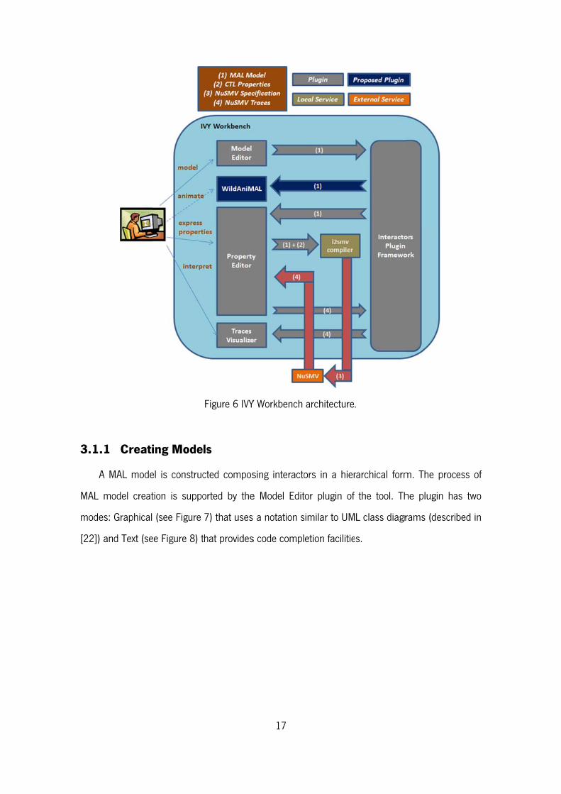
Figure 6 shows the architecture of the tool, added with the proposed WildAniMAL plugin. As
it can be seen, the tool consists on a number of plugins, and uses NuSMV as the verification
engine. In this section the different plugins are described (except WildAniMAL, which will be
discussed later, see Chapter 7).
3.1.
A
MAL
mode
[22])
.1 Creati
A MAL mode
model creat
es: Graphical
and Text (se
ing Mode
el is construc
tion is suppo
(see Figure
ee Figure 8) t
Figure 6 IVY
ls
cted compos
orted by the
7) that uses
that provides
17
Y Workbench
sing interacto
e Model Edit
a notation s
s code compl
architecture
ors in a hier
tor plugin of
similar to UM
etion facilitie
.
rarchical form
the tool. Th
L class diagr
es.
m. The proc
he plugin ha
rams (descri
ess of
as two
bed in
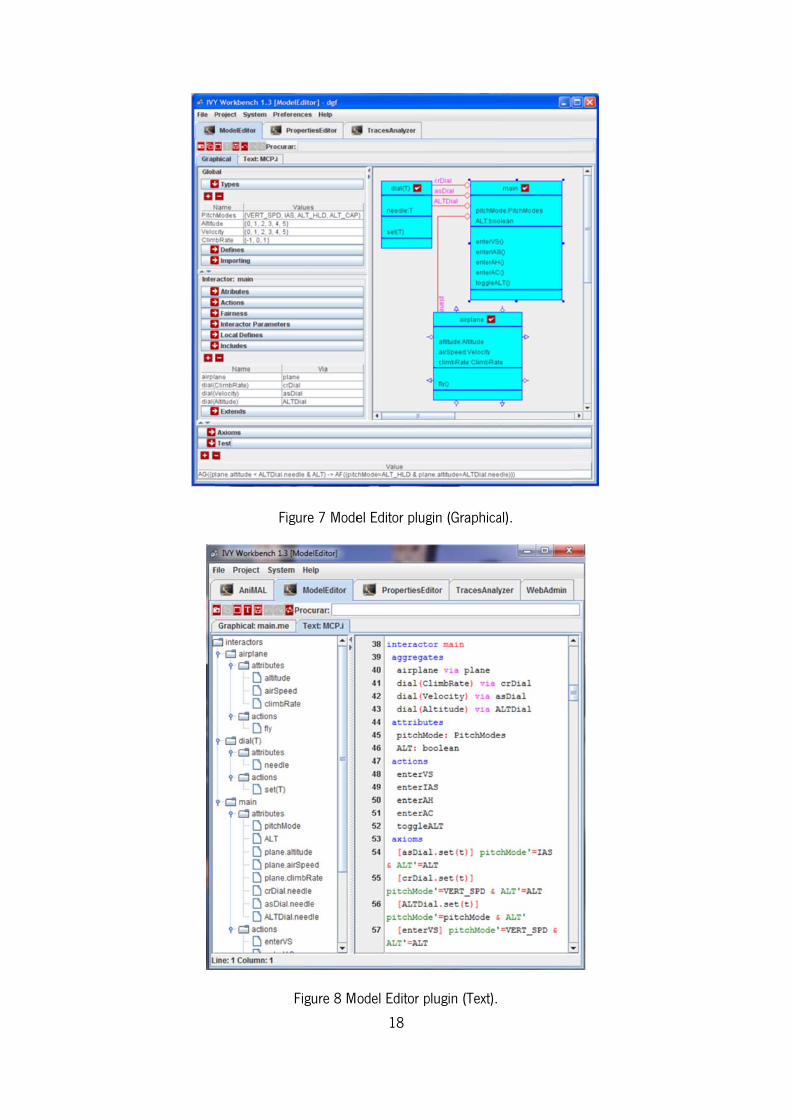
Figure 7 Mode
Figure 8 Mo18
el Editor plug
odel Editor p
gin (Graphica
plugin (Text).
al).
3.1.
T
assum
T
Work
prope
descr
param
the u
the to
for th
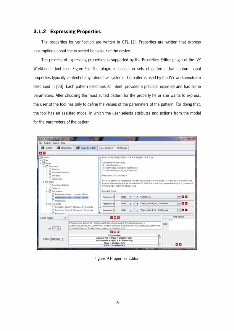
.2 Expre
The propertie
mptions abou
The process
bench tool
erties typicall
ribed in [23]
meters. After
ser of the too
ool has an a
e parameter
ssing Pro
es for verific
ut the expect
of expressin
(see Figure
y verified of
. Each patte
r choosing th
ol has only to
ssisted mod
rs of the patte
operties
cation are w
ted behaviou
g properties
9). The plu
any interactiv
rn describes
he most suite
o define the
e, in which t
ern.
Figure
19
written in CT
r of the devic
is supported
ugin is based
ve system. T
its intent, p
ed pattern fo
values of the
the user sele
9 Properties
L [1]. Prope
ce.
d by the Prop
d on sets o
The patterns
rovides a pra
or the propert
e parameters
ects attribute
s Editor.
erties are wr
perties Edito
f patterns th
used by the I
actical exam
ty he or she
s of the patte
es and action
ritten that ex
or plugin of th
hat capture
IVY workbenc
ple and has
wants to ex
ern. For doing
ns from the
xpress
he IVY
usual
ch are
some
press,
g that,
model
20
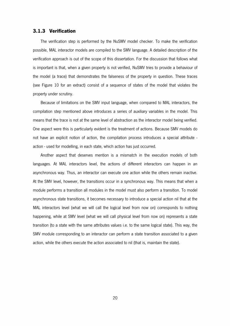
3.1.3 Verification
The verification step is performed by the NuSMV model checker. To make the verification
possible, MAL interactor models are compiled to the SMV language. A detailed description of the
verification approach is out of the scope of this dissertation. For the discussion that follows what
is important is that, when a given property is not verified, NuSMV tries to provide a behaviour of
the model (a trace) that demonstrates the falseness of the property in question. These traces
(see Figure 10 for an extract) consist of a sequence of states of the model that violates the
property under scrutiny.
Because of limitations on the SMV input language, when compared to MAL interactors, the
compilation step mentioned above introduces a series of auxiliary variables in the model. This
means that the trace is not at the same level of abstraction as the interactor model being verified.
One aspect were this is particularly evident is the treatment of actions. Because SMV models do
not have an explicit notion of action, the compilation process introduces a special attribute -
action - used for modelling, in each state, which action has just occurred.
Another aspect that deserves mention is a mismatch in the execution models of both
languages. At MAL interactors level, the actions of different interactors can happen in an
asynchronous way. Thus, an interactor can execute one action while the others remain inactive.
At the SMV level, however, the transitions occur in a synchronous way. This means that when a
module performs a transition all modules in the model must also perform a transition. To model
asynchronous state transitions, it becomes necessary to introduce a special action nil that at the
MAL interactors level (what we will call the logical level from now on) corresponds to nothing
happening, while at SMV level (what we will call physical level from now on) represents a state
transition (to a state with the same attributes values i.e. to the same logical state). This way, the
SMV module corresponding to an interactor can perform a state transition associated to a given
action, while the others execute the action associated to nil (that is, maintain the state).
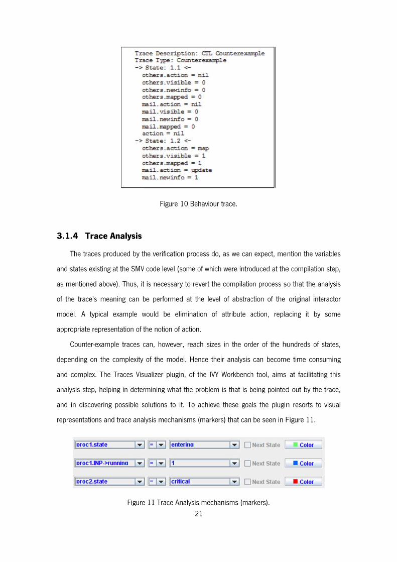
3.1.
T
and s
as m
of the
mode
appro
C
depen
and c
analy
and i
repre
.4 Trace
The traces pr
states existing
entioned abo
e trace's me
el. A typical
opriate repres
Counter-exam
nding on the
complex. The
ysis step, hel
in discoverin
esentations a
Analysis
roduced by t
g at the SMV
ove). Thus, it
eaning can b
l example w
sentation of t
mple traces c
e complexity
e Traces Vis
ping in deter
ng possible s
nd trace ana
Figure
Figure
he verificatio
V code level (s
t is necessar
be performe
would be el
the notion of
can, howeve
of the mod
sualizer plugi
rmining what
solutions to i
lysis mechan
e 11 Trace A21
10 Behaviou
on process d
some of whic
ry to revert th
d at the lev
limination o
f action.
er, reach size
el. Hence th
in, of the IVY
t the problem
it. To achiev
nisms (marke
Analysis mech
ur trace.
o, as we can
ch were intro
he compilatio
vel of abstrac
f attribute a
es in the ord
heir analysis
Y Workbench
m is that is b
ve these goa
ers) that can
hanisms (ma
n expect, men
oduced at the
on process so
ction of the
action, repla
der of the hu
can become
h tool, aims
being pointed
als the plugin
be seen in F
rkers).
ntion the var
e compilation
o that the an
original inte
acing it by
undreds of s
e time cons
at facilitatin
d out by the
n resorts to
Figure 11.
riables
n step,
nalysis
eractor
some
states,
uming
ng this
trace,
visual
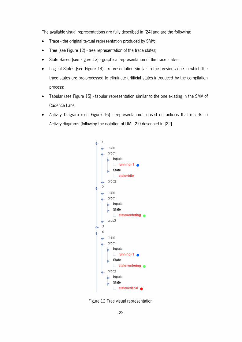
T
The available
Trace - th
Tree (see
State Bas
Logical S
trace stat
process;
Tabular (s
Cadence
Activity D
Activity di
visual repres
he original tex
Figure 12) -
sed (see Figu
tates (see Fi
tes are pre-p
see Figure 1
Labs;
Diagram (see
iagrams (follo
sentations ar
xtual represe
tree represe
re 13) - grap
igure 14) - r
rocessed to
5) - tabular r
e Figure 16)
owing the no
Figure 12 Tr
22
re fully descr
entation prod
entation of th
phical represe
representatio
eliminate art
representatio
) - represen
otation of UM
ree visual rep
ibed in [24]
uced by SMV
e trace state
entation of th
n similar to
tificial states
on similar to
tation focuse
L 2.0 describ
presentation.
and are the f
V;
es;
he trace state
the previous
introduced b
the one exis
ed on action
bed in [22].
.
following:
es;
s one in whic
by the comp
sting in the S
ns that reso
ch the
pilation
SMV of
orts to
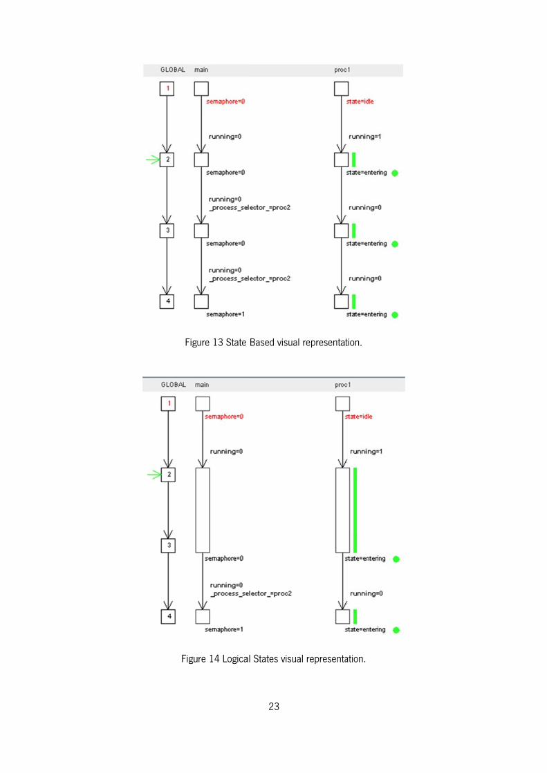
Figu
Figu
ure 13 State
re 14 Logica
23
Based visua
al States visu
al representat
al representa
tion.
ation.
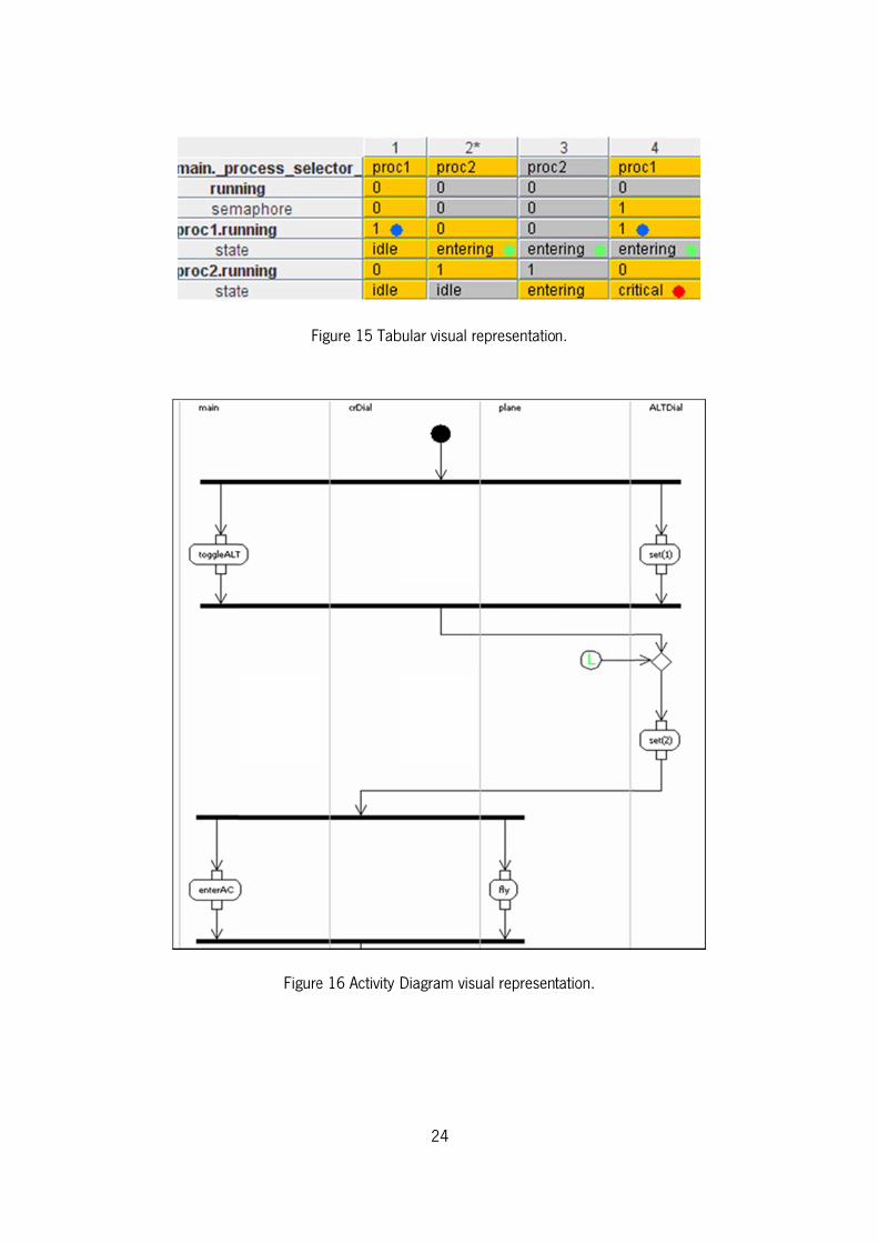
F
Figure
Figure 15 Tab
e 16 Activity
24
bular visual r
Diagram vis
representatio
ual represent
n.
tation.
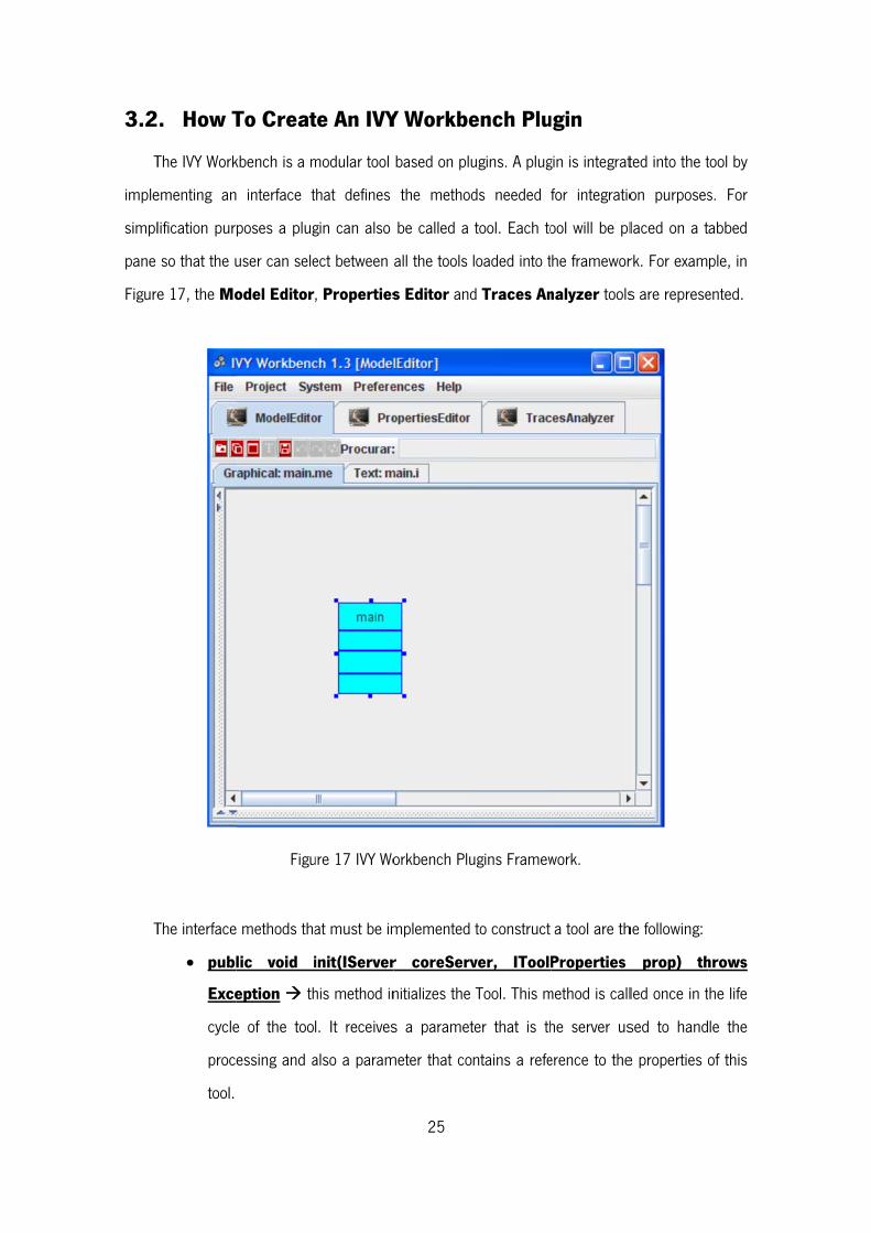
3.2
T
imple
simpl
pane
Figure
T
. How T
The IVY Work
ementing an
lification pur
so that the u
e 17, the Mo
The interface
publ
Exce
cycle
proc
tool.
To Creat
kbench is a m
interface t
poses a plug
user can sele
odel Editor
Figu
e methods tha
lic void i
eption th
e of the too
essing and a
te An IVY
modular tool
that defines
gin can also
ect between
, Properties
ure 17 IVY Wo
at must be im
init(IServer
his method in
l. It receives
also a param
25
Y Workbe
based on plu
the method
be called a
all the tools
s Editor and
orkbench Plu
mplemented
r coreServ
nitializes the
s a paramet
meter that co
ench Plu
ugins. A plug
ds needed
tool. Each to
loaded into t
d Traces An
ugins Framew
to construct
ver, IToolP
Tool. This m
ter that is th
ntains a refe
ugin
gin is integrat
for integratio
ool will be pl
he framewor
nalyzer tools
work.
a tool are th
Properties
method is call
he server us
erence to the
ted into the t
on purposes
laced on a t
rk. For exam
s are represe
he following:
prop) th
led once in t
sed to hand
e properties o
tool by
s. For
abbed
ple, in
ented.
hrows
he life
le the
of this
26
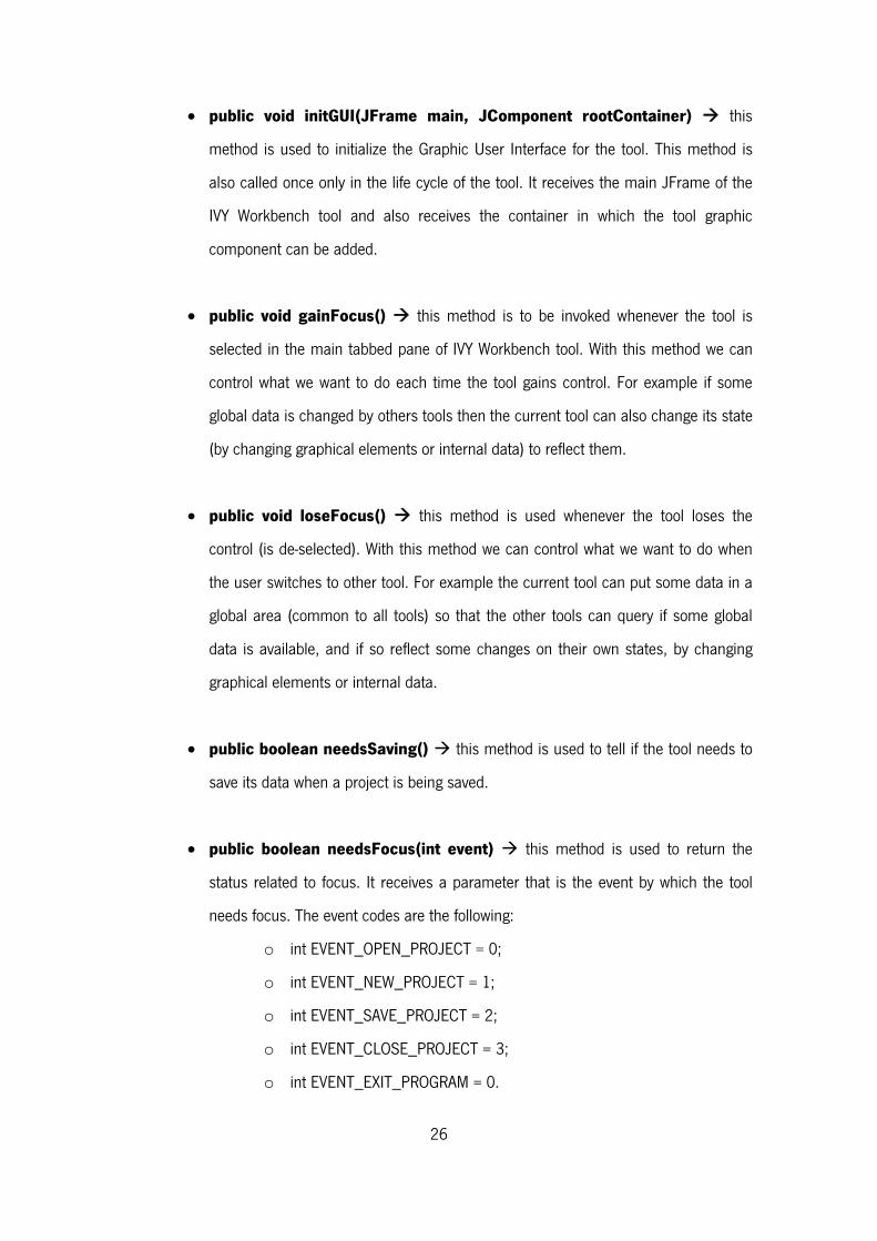
public void initGUI(JFrame main, JComponent rootContainer) this
method is used to initialize the Graphic User Interface for the tool. This method is
also called once only in the life cycle of the tool. It receives the main JFrame of the
IVY Workbench tool and also receives the container in which the tool graphic
component can be added.
public void gainFocus() this method is to be invoked whenever the tool is
selected in the main tabbed pane of IVY Workbench tool. With this method we can
control what we want to do each time the tool gains control. For example if some
global data is changed by others tools then the current tool can also change its state
(by changing graphical elements or internal data) to reflect them.
public void loseFocus() this method is used whenever the tool loses the
control (is de-selected). With this method we can control what we want to do when
the user switches to other tool. For example the current tool can put some data in a
global area (common to all tools) so that the other tools can query if some global
data is available, and if so reflect some changes on their own states, by changing
graphical elements or internal data.
public boolean needsSaving() this method is used to tell if the tool needs to
save its data when a project is being saved.
public boolean needsFocus(int event) this method is used to return the
status related to focus. It receives a parameter that is the event by which the tool
needs focus. The event codes are the following:
o int EVENT_OPEN_PROJECT = 0;
o int EVENT_NEW_PROJECT = 1;
o int EVENT_SAVE_PROJECT = 2;
o int EVENT_CLOSE_PROJECT = 3;
o int EVENT_EXIT_PROGRAM = 0.
27
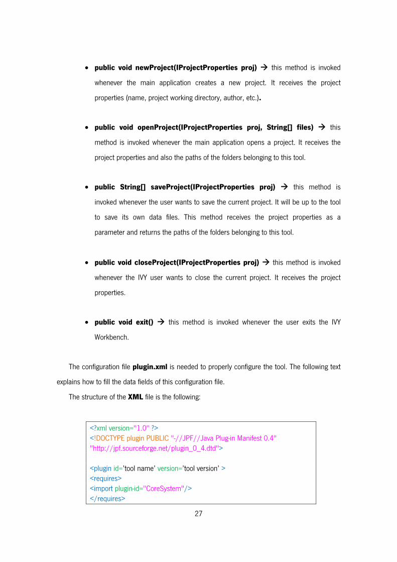
public void newProject(IProjectProperties proj) this method is invoked
whenever the main application creates a new project. It receives the project
properties (name, project working directory, author, etc.).
public void openProject(IProjectProperties proj, String[] files) this
method is invoked whenever the main application opens a project. It receives the
project properties and also the paths of the folders belonging to this tool.
public String[] saveProject(IProjectProperties proj) this method is
invoked whenever the user wants to save the current project. It will be up to the tool
to save its own data files. This method receives the project properties as a
parameter and returns the paths of the folders belonging to this tool.
public void closeProject(IProjectProperties proj) this method is invoked
whenever the IVY user wants to close the current project. It receives the project
properties.
public void exit() this method is invoked whenever the user exits the IVY
Workbench.
The configuration file plugin.xml is needed to properly configure the tool. The following text
explains how to fill the data fields of this configuration file.
The structure of the XML file is the following:
<?xml version="1.0" ?> <!DOCTYPE plugin PUBLIC "-//JPF//Java Plug-in Manifest 0.4" "http://jpf.sourceforge.net/plugin_0_4.dtd"> <plugin id=’tool name’ version=’tool version’ > <requires> <import plugin-id="CoreSystem"/> </requires>
28
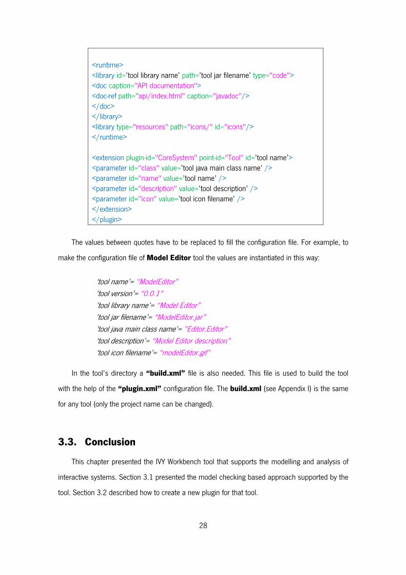
<runtime> <library id=’tool library name’ path=’tool jar filename’ type="code"> <doc caption="API documentation"> <doc-ref path="api/index.html" caption="javadoc"/> </doc> </library> <library type="resources" path="icons/" id="icons"/> </runtime> <extension plugin-id="CoreSystem" point-id="Tool" id=’tool name’> <parameter id="class" value=’tool java main class name’ /> <parameter id="name" value=’tool name’ /> <parameter id="description" value=’tool description’ /> <parameter id="icon" value=’tool icon filename’ /> </extension> </plugin>
The values between quotes have to be replaced to fill the configuration file. For example, to
make the configuration file of Model Editor tool the values are instantiated in this way:
‘tool name’= “ModelEditor” ’tool version’= “0.0.1” ’tool library name’= “Model Editor” ’tool jar filename’= “ModelEditor.jar” ’tool java main class name’= ”Editor.Editor” ‘tool description’= “Model Editor description” ‘tool icon filename’= “modelEditor.gif”
In the tool’s directory a “build.xml” file is also needed. This file is used to build the tool
with the help of the “plugin.xml” configuration file. The build.xml (see Appendix I) is the same
for any tool (only the project name can be changed).
3.3. Conclusion
This chapter presented the IVY Workbench tool that supports the modelling and analysis of
interactive systems. Section 3.1 presented the model checking based approach supported by the
tool. Section 3.2 described how to create a new plugin for that tool.
29
Chapter 4 – Related Work
This chapter describes CTTE (ConcurTaskTrees Environment) a task modeling tool that has
animation and simulation strategies that are similar to the ones intended to be used on the
proposed MAL models animator plugin. A previous IVY Workbench plugin - aniMAL - that had a
similar goal to this work will also be described.
4.1. CTTE
CTTE5 (see Figure 18) is an environment for editing and analysing task models. Its main goal
is to support the design of interactive applications focusing in the humans and their activities.
In [25] the concepts behind tasks models are presented. In is an important model because it
indicates the logical activities that an application can support. A task is defined as an activity that
should be performed by the user to reach a goal in the system. A goal can be a desired
modification of state or a query to obtain information on the current state of the system. Figure
19 presents an example of a Tasks model.
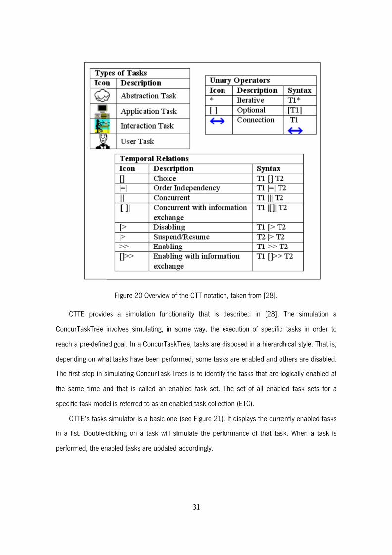
CTTE uses ConcurTaskTrees (CTT), introduced by Fabio Paternó in [26] and [27]. CTT is a
graphical notation (see Figure 20 for an example) with a set of operators used to describe the
relationships between tasks.
5 Available at http://giove.isti.cnr.it/tools/CTTE (last visited 27/10/2012).
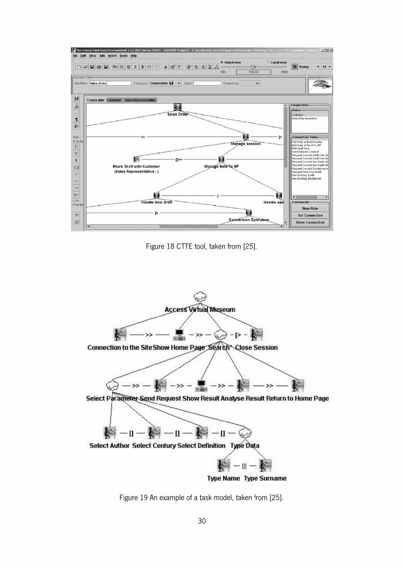
Figure 19
Figure 18 CT
9 An example
30
TTE tool, take
e of a task m
en from [25]
model, taken f
.
from [25].
C
Conc
reach
depen
The f
the s
speci
C
in a
perfo
CTTE provid
urTaskTree
h a pre-define
nding on wha
first step in s
same time a
fic task mod
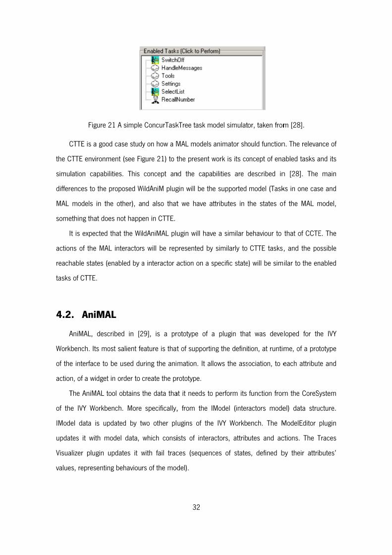
CTTE’s tasks
list. Double-c
rmed, the en
Figure 20
es a simula
involves sim
ed goal. In a
at tasks have
simulating Co
nd that is c
el is referred
s simulator is
clicking on a
nabled tasks
0 Overview of
ation functio
ulating, in s
ConcurTaskT
e been perfor
oncurTask-Tr
alled an ena
to as an ena
a basic one
a task will si
are updated
31
f the CTT not
onality that
some way, t
kTree, tasks a
rmed, some
rees is to ide
abled task s
abled task co
e (see Figure
imulate the
accordingly.
tation, taken
is described
he execution
are disposed
tasks are en
entify the task
set. The set
ollection (ETC
21). It displa
performance
from [28].
d in [28]. T
n of specific
in a hierarch
abled and ot
ks that are lo
of all enable
C).
ays the curre
e of that task
The simulat
tasks in ord
hical style. T
thers are dis
ogically enab
ed task sets
ently enabled
k. When a t
tion a
der to
hat is,
abled.
bled at
for a
d tasks
task is
C
the C
simul
differe
MAL
some
I
action
reach
tasks
4.2
A
Work
of the
action
T
of the
IMode
updat
Visua
value
Figure
CTTE is a goo
CTTE environ
lation capab
ences to the
models in t
ething that do
t is expected
ns of the MA
hable states (
of CTTE.
. AniMA
AniMAL, des
bench. Its m
e interface to
n, of a widge
The AniMAL
e IVY Workb
el data is u
tes it with m
alizer plugin
s, representi
21 A simple
od case stud
ment (see Fi
bilities. This
proposed W
the other), a
oes not happ
d that the Wi
AL interactor
(enabled by a
AL
scribed in [2
most salient fe
o be used du
t in order to
tool obtains
bench. More
pdated by t
model data,
updates it w
ing behaviou
e ConcurTask
y on how a M
gure 21) to t
concept an
WildAniM plug
nd also that
en in CTTE.
ldAniMAL plu
s will be rep
a interactor a
29], is a pr
eature is that
uring the ani
create the pr
the data tha
specifically,
two other pl
which consi
with fail trac
rs of the mod
32
kTree task m
MAL models
the present w
nd the capa
gin will be th
t we have a
ugin will hav
presented by
action on a s
rototype of a
t of supportin
mation. It al
rototype.
at it needs to
, from the I
ugins of the
ists of intera
ces (sequenc
del).
odel simulat
animator sho
work is its co
bilities are
e supported
ttributes in t
ve a similar b
y similarly to
specific state
a plugin tha
ng the definit
lows the ass
o perform its
Model (inter
e IVY Workbe
actors, attrib
ces of state
or, taken from
ould function
oncept of ena
described in
model (Task
the states of
behaviour to
CTTE tasks,
e) will be sim
at was deve
tion, at runtim
ociation, to e
function from
ractors mode
ench. The M
utes and ac
s, defined b
m [28].
n. The releva
abled tasks a
n [28]. The
ks in one cas
of the MAL m
that of CCTE
, and the po
milar to the en
loped for th
me, of a pro
each attribut
m the CoreS
el) data stru
ModelEditor
ctions. The T
by their attri
nce of
and its
main
se and
model,
E. The
ossible
nabled
he IVY
totype
te and
System
ucture.
plugin
Traces
butes’
W
mode
or ma
choos
have
autom
T
I
attrib
show
T
graph
these
provid
propt
intera
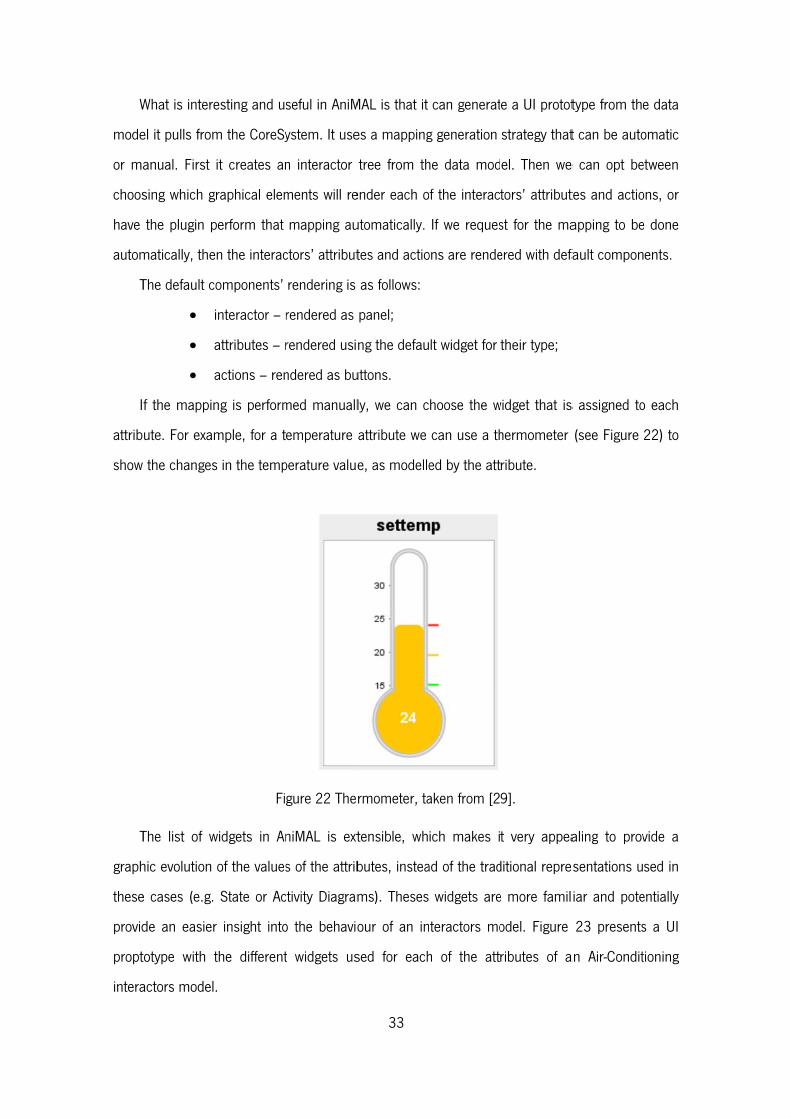
What is intere
el it pulls from
anual. First
sing which g
the plugin p
matically, the
The default c
f the mappin
ute. For exam
w the changes
The list of w
hic evolution
e cases (e.g.
de an easier
totype with t
actors model
esting and us
m the CoreSy
it creates an
graphical elem
perform that
en the interac
components’
interactor – r
attributes – r
actions – ren
ng is perform
mple, for a t
s in the temp
Fi
widgets in An
of the values
State or Ac
r insight into
the different
.
seful in AniM
ystem. It use
n interactor
ments will re
mapping au
ctors’ attribut
rendering is
rendered as
rendered usi
ndered as bu
med manuall
emperature
perature value
gure 22 The
niMAL is ext
s of the attrib
ctivity Diagram
o the behavio
t widgets us
33
MAL is that it
es a mapping
tree from th
ender each o
utomatically.
tes and actio
as follows:
panel;
ng the defau
uttons.
ly, we can c
attribute we
e, as modelle
rmometer, ta
tensible, wh
butes, instea
ms). Theses
our of an in
sed for each
can generat
g generation
he data mod
of the interac
If we reques
ons are rende
lt widget for
hoose the w
can use a th
ed by the att
aken from [2
ich makes i
ad of the trad
widgets are
nteractors mo
h of the att
e a UI protot
strategy that
el. Then we
tors’ attribut
st for the ma
ered with defa
their type;
widget that is
hermometer
ribute.
9].
t very appea
ditional repre
e more famil
odel. Figure
ributes of a
type from the
t can be auto
e can opt be
tes and actio
apping to be
fault compon
s assigned to
(see Figure
aling to prov
esentations u
iar and pote
23 presents
an Air-Condit
e data
omatic
etween
ons, or
e done
ents.
o each
22) to
vide a
sed in
entially
s a UI
tioning
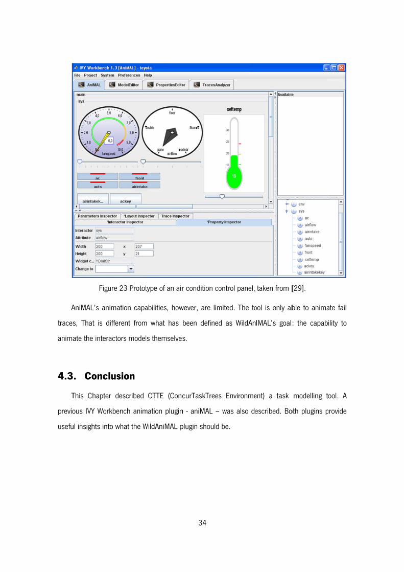
A
traces
anima
4.3
T
previo
usefu
Figu
AniMAL’s an
s, That is d
ate the intera
. Concl
This Chapter
ous IVY Work
ul insights int
ure 23 Protot
imation capa
ifferent from
actors model
lusion
r described
kbench anim
to what the W
type of an air
abilities, how
m what has
ls themselves
CTTE (Conc
mation plugin
WildAniMAL p
34
r condition co
wever, are lim
been defined
s.
curTaskTrees
n - aniMAL –
plugin should
ontrol panel,
mited. The to
d as WildAn
s Environme
was also de
be.
taken from [
ool is only ab
IMAL’s goal:
ent) a task
escribed. Bo
[29].
ble to anima
: the capabi
modelling to
oth plugins p
ate fail
ility to
ool. A
rovide
35
Chapter 5 – WildAniMAL
Implementation Approaches
This chapter discusses possible WildAniMAL implementation approaches. Section 5.1
discusses three implementation alternatives. Section 5.2 presents the chosen implementation
approach: NuSMV Simulation Capabilities.
The NuSMV model checker provides an interactive shell where commands can be entered.
The commands are grouped by the functionality they provide. There are eight main groups:
Model Reading and Building, Simulation, Checking Specifications, Bounded Model Checking,
Checking PSL Specifications, Execution, Traces, and Administration.
In the context of the present work, we are interested in those commands that help perform
an interactive simulation of a NuSMV specification. Having that in mind, the groups of commands
which are important to mention are: Model Reading and Building, and Simulation.
Sections 5.2.1 and 5.2.2 provide commands’ descriptions that are focused on those aspects
(options and environment variables) that are effectively used in this work. More detailed
descriptions can be found in [12].
Section 5.2.3 provides a NuSMV simulation example where all the presented commands are
used.
5.1. Implementation Approaches
In this Section, the main approaches to implementing the WildAniMAL plugin will be
analysed. Three approaches are considered. Section 5.1.1 looks at the possibility of generating
and using a Finite State Machine representation of the MAL interactors model to drive the
36
animation. Section 5.1.2 looks at using the BDD representation of the MAL interactors model
(created by NuSMV, the verification engine used by IVY Workbench) instead of creating our own
finite state machine. Finally, Section 5.1.3 looks at the possibility of using NuSMV's simulation
commands, available on its interactive mode, to perform the animation.
5.1.1 Generating a Finite State Machine
This approach can be described as transforming the MAL interactors model into a Finite
State Machine (FSM) model. An introduction to the theory behind FSM is available in Section 2.3.
To use this approach an algorithm to translate MAL models into some FSM representation
has to be developed and implemented. That work can be complex and time consuming and also
tests of the algorithm implementation's correctness are needed. Due to these reasons this
approach can be risky, and good results cannot be guaranteed beforehand.
The main advantage of this approach is that only the original MAL model is used, and the
results from the simulation process are easily interpreted in the context of, and incorporated into,
the MAL’s model iterative creation process. Other advantage is that, if this approach can be
efficiently implemented, then it will be as easy to perform an interactive simulation of the MAL’s
model (creating the FSM one step at a time) as it will the full generation of its FSM model.
Because the algorithm will be custom made it will be easily adaptable to any need desired.
To face this approach's risks, NuSMV's flat model FSM capabilities can be used. These
capabilities are supported by the following commands:
build flat model - Compiles the flattened hierarchy into a Scalar FSM;
build boolean model - Compiles the flattened hierarchy into boolean Scalar FSM;
write flat model - Writes a flat model to a file;
write boolean model - Writes a flat and boolean model to a file.
However, if the NuSMV FSM capabilities are used, then the main advantage stated above
can be lost, due to the translation process between MAL model and the NuSMV generated FSM
model. The simulation will no longer happen at the abstraction level of the MAL models, but at
the level of the NuSMV specifications created from those models.
37
5.1.2 NuSMV Binary Decision Diagrams
This approach can be described as using the BDD representation of the MAL interactors
model, created by the NuSMV model checker, to perform the animation.
Binary Decision Diagrams (presented in Section 2.4) are used by the NuSMV model checker
to perform model checking over the NuSMV model. These diagrams are not easily
understandable and can be difficult to use for the purpose of implementing the WildAniMAL
plugin.
This approach is not the best one because the initial MAL interactors model is translated to a
NuSMV model that is read by NuSMV model checker and transformed into BDD. Because two
translations steps are made, doing the analysis of the results obtained by animating the BDD,
and using them to help the modeling process of a MAL interactors model, will be a daunting task.
This is because several artificial variables can be added and transformations made between the
two models and the BDD.
5.1.3 NuSMV Simulation Capabilities
The NuSMV model checker has simulations commands that can be used to help implement
the proposed MAL interactors model animator plugin. An example of the NuSMV’s simulation
capabilities is presented in Figure 24.
F
Availa
when
the n
from
with t
the fo
T
WildA
are n
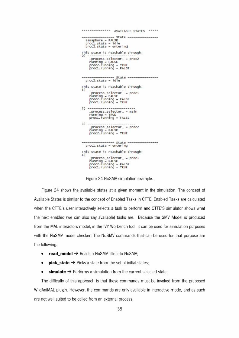
Figure 24 sho
able States is
n the CTTE’s
next enabled
the MAL inte
the NuSMV m
ollowing:
read_mo
pick_sta
simulate
The difficulty
AniMAL plugi
ot well suited
F
ows the ava
s similar to th
user interac
(we can als
eractors mod
model check
odel Rea
ate Picks
e Perform
of this appro
n. However,
d to be called
Figure 24 Nu
ilable states
he concept o
ctively selects
so say availa
del, in the IVY
ker. The NuS
ds a NuSMV
a state from
ms a simulatio
oach is that
the comman
d from an ext
38
uSMV simula
at a given m
of Enabled Ta
s a task to p
able) tasks a
Y Worbench t
SMV comman
V fille into NuS
the set of in
on from the c
these comm
nds are only
ternal proces
tion example
moment in t
asks in CTTE
perform and
re. Because
tool, it can be
nds that can
SMV;
nitial states;
current selec
mands must
available in
ss.
e.
he simulatio
. Enabled Ta
CTTE’S simu
e the SMV M
e used for sim
n be used for
ted state;
be invoked f
interactive m
on. The conc
asks are calc
ulator shows
Model is pro
mulation pur
r that purpos
from the pro
mode, and as
cept of
ulated
s what
duced
rposes
se are
posed
s such
39
Conceptually the main problem with this implementation approach is that the SMV Model is
slightly different from the initial MAL interactors model (as stated in Section 5.1.2). Therefore a
process of constant translation and interpretation of animation results from SMV model to MAL
model has to be made and that can be problematic and inefficient. Nevertheless, this is still
better than directly using BDDs (NuSMV uses the BDDs to run the simulation), were there would
be two steps between the original model and the representation our tool would use to support the
animation.
Considering the above, this approach was the chosen one for the implementation of the
WildAniMAL plugin.
5.2. NuSMV Interactive Shell
The NuSMV Interactive Shell offers an interaction mode that initiates a read-eval-print loop, in
which commands can be executed. The activation of the shell is done by invoking the model
checker with the “-int” option:
system prompt> NuSMV -int <RET>
NuSMV>
When the default “NUSMV>” shell prompt is displayed, the system is ready to accept and
execute user commands.
A NuSMV command is a sequence of words. The first word represents the command to be
executed and the remaining words are its arguments. With the “set” command it is possible to
assign values to environment variables, which in turn influence the behaviour of the commands.
5.2.1 Model Reading And Building
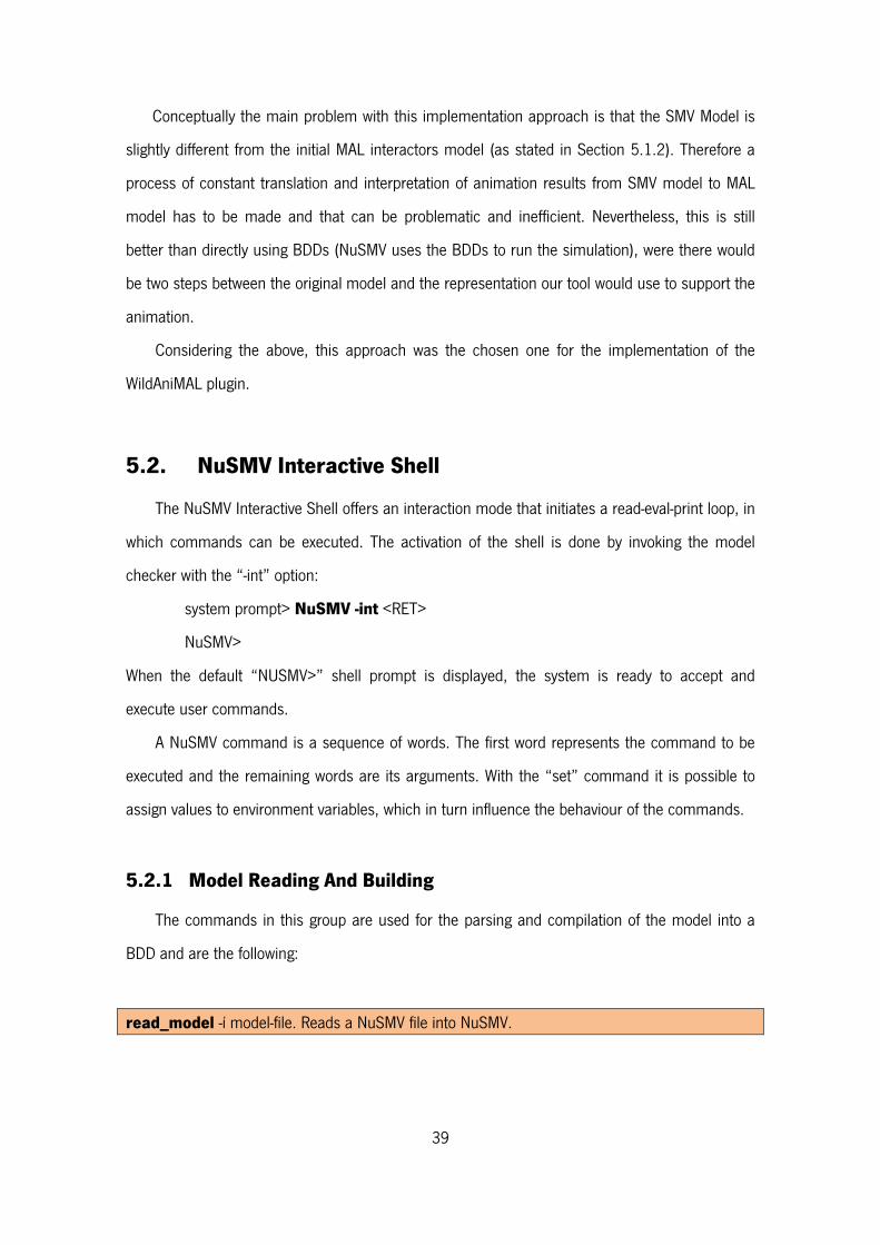
The commands in this group are used for the parsing and compilation of the model into a
BDD and are the following:
read_model -í model-file. Reads a NuSMV file into NuSMV.
40
If the -i option is not specified, the command reads the file specified in the environment
variable Input_File. If the option is specified the command sets the environment variable
input_file to model-file, and reads the model from the specified file.
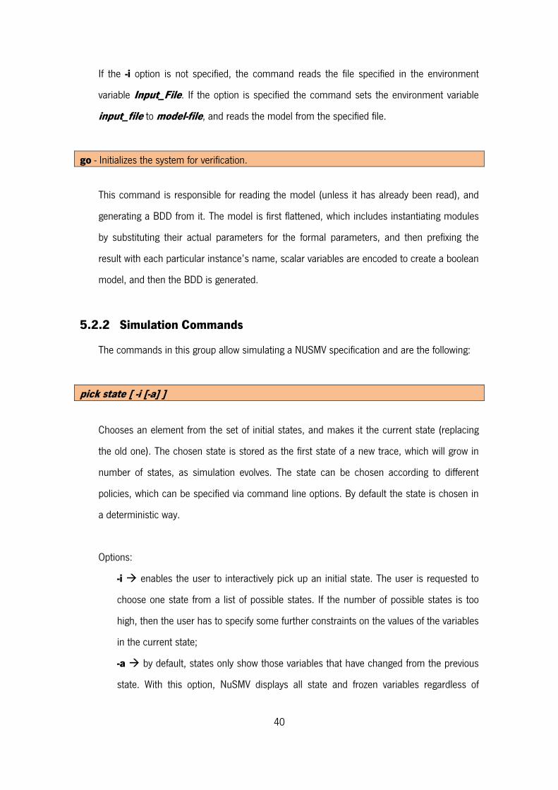
go - Initializes the system for verification.
This command is responsible for reading the model (unless it has already been read), and
generating a BDD from it. The model is first flattened, which includes instantiating modules
by substituting their actual parameters for the formal parameters, and then prefixing the
result with each particular instance’s name, scalar variables are encoded to create a boolean
model, and then the BDD is generated.
5.2.2 Simulation Commands
The commands in this group allow simulating a NUSMV specification and are the following:
pick state [ -i [-a] ]
Chooses an element from the set of initial states, and makes it the current state (replacing
the old one). The chosen state is stored as the first state of a new trace, which will grow in
number of states, as simulation evolves. The state can be chosen according to different
policies, which can be specified via command line options. By default the state is chosen in
a deterministic way.
Options:
-i enables the user to interactively pick up an initial state. The user is requested to
choose one state from a list of possible states. If the number of possible states is too
high, then the user has to specify some further constraints on the values of the variables
in the current state;
-a by default, states only show those variables that have changed from the previous
state. With this option, NuSMV displays all state and frozen variables regardless of
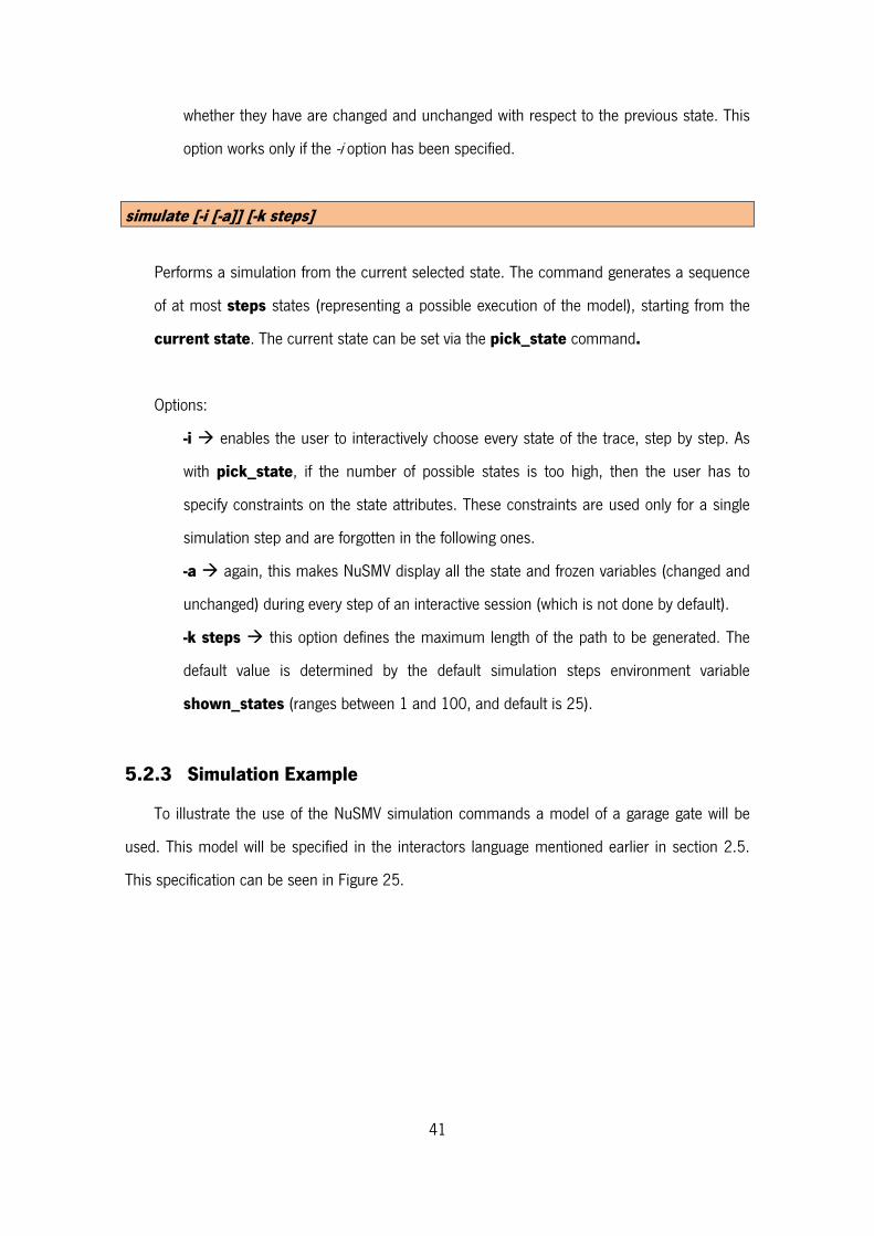
41
whether they have are changed and unchanged with respect to the previous state. This
option works only if the -i option has been specified.
simulate [-i [-a]] [-k steps]
Performs a simulation from the current selected state. The command generates a sequence
of at most steps states (representing a possible execution of the model), starting from the
current state. The current state can be set via the pick_state command.
Options:
-i enables the user to interactively choose every state of the trace, step by step. As
with pick_state, if the number of possible states is too high, then the user has to
specify constraints on the state attributes. These constraints are used only for a single
simulation step and are forgotten in the following ones.
-a again, this makes NuSMV display all the state and frozen variables (changed and
unchanged) during every step of an interactive session (which is not done by default).
-k steps this option defines the maximum length of the path to be generated. The
default value is determined by the default simulation steps environment variable
shown_states (ranges between 1 and 100, and default is 25).
5.2.3 Simulation Example
To illustrate the use of the NuSMV simulation commands a model of a garage gate will be
used. This model will be specified in the interactors language mentioned earlier in section 2.5.
This specification can be seen in Figure 25.
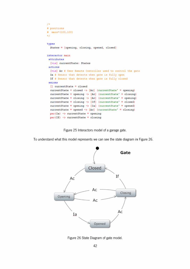
TTo understan
Figu
nd what this m
F
ure 25 Intera
model repres
Figure 26 Sta
42
ctors model
sents we can
ate Diagram o
of a garage g
see the stat
of gate mode
gate.
te diagram in
el.
n Figure 26.
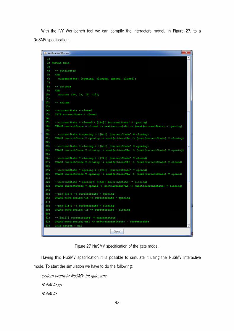
W
NuSM
H
mode
s
N
N
With the IVY
MV specificat
Having this N
e. To start the
system prom
NuSMV> go
NuSMV>
Y Workbench
ion.
Figure
NuSMV spec
e simulation
mpt> NuSMV
tool we ca
e 27 NuSMV
cification it is
we have to d
-int gate.smv
43
an compile t
specification
s possible to
do the followi
v
the interacto
n of the gate
o simulate it
ing:
ors model, in
model.
t using the N
n Figure 27
NuSMV inter
, to a
ractive
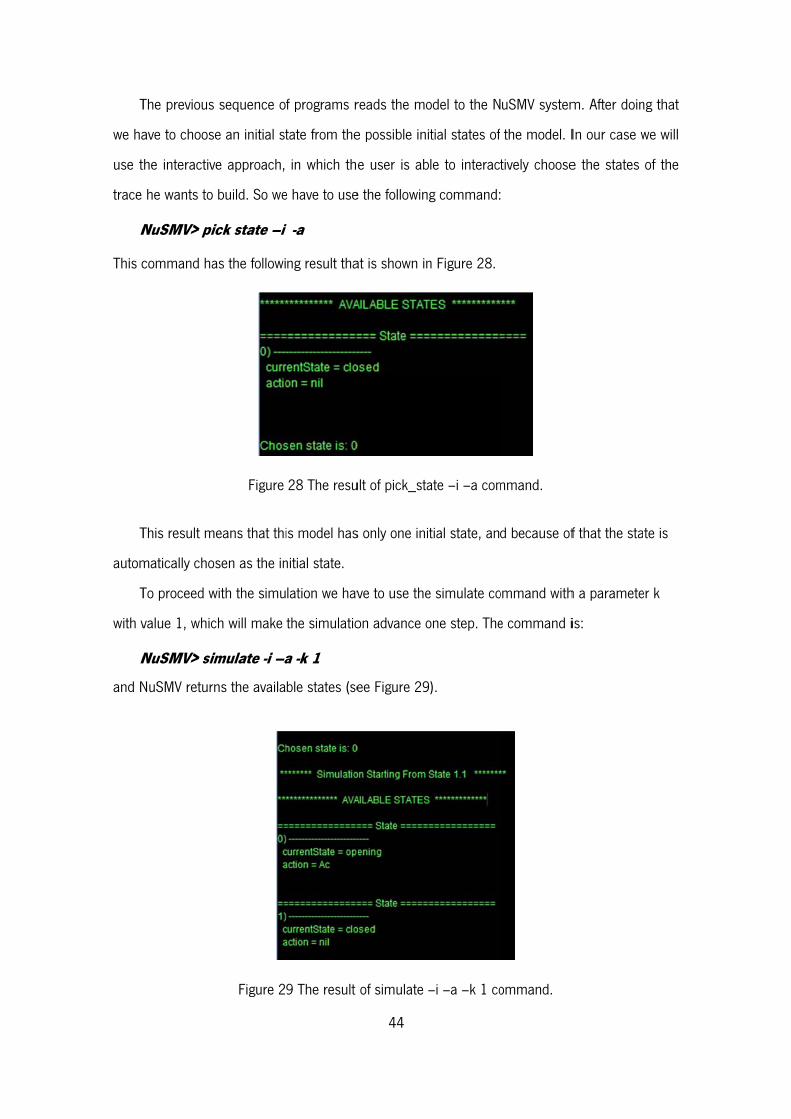
T
we ha
use t
trace
N
This c
T
autom
T
with v
N
and N
The previous
ave to choos
the interactiv
he wants to
NuSMV> pic
command ha
This result m
matically cho
To proceed w
value 1, whic
NuSMV> sim
NuSMV return
sequence o
e an initial st
ve approach,
build. So we
ick state –i
as the followi
Figure
eans that thi
sen as the in
with the simu
ch will make
imulate -i –a
ns the availa
Figure 2
f programs r
tate from the
in which the
e have to use
i -a
ng result tha
28 The resu
is model has
nitial state.
lation we hav
the simulatio
a -k 1
ble states (se
9 The result
44
reads the mo
e possible ini
e user is ab
e the followin
at is shown in
ult of pick_sta
s only one ini
ve to use the
on advance o
ee Figure 29
of simulate –
odel to the N
tial states of
le to interact
g command:
n Figure 28.
ate –i –a com
tial state, an
e simulate co
one step. The
).
–i –a –k 1 co
uSMV system
the model. I
tively choose
mmand.
d because of
ommand with
e command i
ommand.
m. After doin
In our case w
e the states
f that the sta
h a paramete
is:
ng that
we will
of the
te is
er k
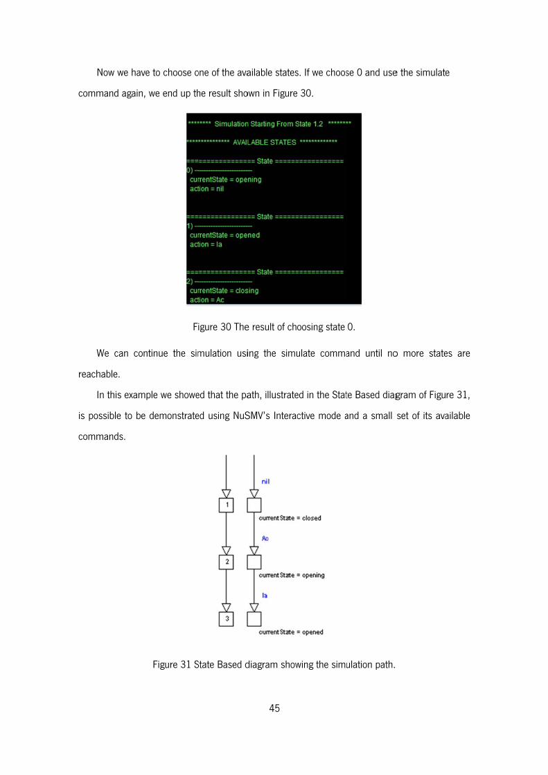
N
comm
W
reach
I
is pos
comm
Now we have
mand again,
We can cont
hable.
n this examp
ssible to be
mands.
e to choose o
we end up th
F
tinue the sim
ple we showe
demonstrate
Figure 31 S
one of the ava
he result sho
igure 30 The
mulation usi
ed that the pa
ed using NuS
State Based d
45
ailable states
own in Figure
e result of ch
ing the simu
ath, illustrate
SMV’s Interac
diagram show
s. If we choos
30.
oosing state
ulate comma
ed in the Stat
ctive mode a
wing the simu
se 0 and use
0.
and until no
te Based diag
and a small
ulation path.
e the simulate
o more state
gram of Figu
set of its ava
e
es are
re 31,
ailable

46
5.3. Conclusion
In this chapter we described the NuSMV Interactive Mode and its available commands. To
more effectively illustrate it we presented a real example of a model: a garage gate. The model
was specified in the MAL Interactors language, compiled to a NuSMV specification, and finally a
simulation was carried out. That simulation used the commands that were previous presented.
We can conclude that NuSMV simulation commands can be useful to implement a MAL
Interactors model animator because the needed output and general mechanism is easily
available and ready to use.
47
Chapter 6 – WildAniMAL
Implementation
This chapter describes the implementation of WildAniMAL as a plugin for the IVY Workbench
tool. An architectural view with UML diagrams is provided. To provide more detail on the
implementation, an explanation of the main methods is presented.
6.1. WildAniMAL’s Architecture
Because the JAVA programming language was used, the architecture of the WildAniMAL
plugin can be easily explained by using UML diagrams for each of the Java packages created.
This scheme for presenting the architecture is well suited to provide the “main picture” of the
implementation.
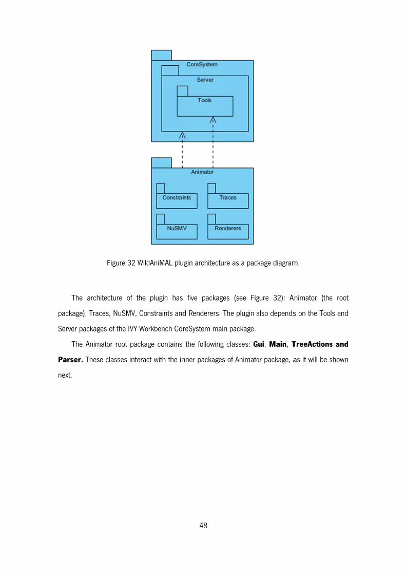
T
packa
Serve
T
Pars
next.
F
The architec
age), Traces,
er packages o
The Animato
ser. These cl
Figure 32 Wild
cture of the
, NuSMV, Co
of the IVY Wo
r root packa
asses interac
dAniMAL plu
plugin has
onstraints and
orkbench Cor
age contains
ct with the in
48
gin architect
five packag
d Renderers.
reSystem ma
the followin
nner package
ture as a pac
ges (see Fig
The plugin a
ain package.
g classes: G
es of Animato
ckage diagram
gure 32): A
also depends
Gui, Main, T
or package, a
m.
Animator (the
s on the Too
TreeActions
as it will be s
e root
ls and
s and
shown

T
the IV
initG
T
interf
interf
The Main cl
VY Workbenc
Gui method o
The Gui clas
face of the p
face. It also h
F
ass is respo
h tool as exp
of the interfac
ss (see Figur
lugin. It has
handles the e
Figure 33 Ma
nsible for im
plained in Sec
ce.
re 33), as th
the code for
events for the
49
ain package c
mplementing
ction 3.2. In
he name ma
r displaying t
e buttons pre
class diagram
the interface
particular, it
ay give a clu
the buttons,
esses.
m.
e needed to c
initializes the
ue, handles t
panels and t
create a plug
e Gui class,
the graphica
tables, used
gin for
in the
al user
in the
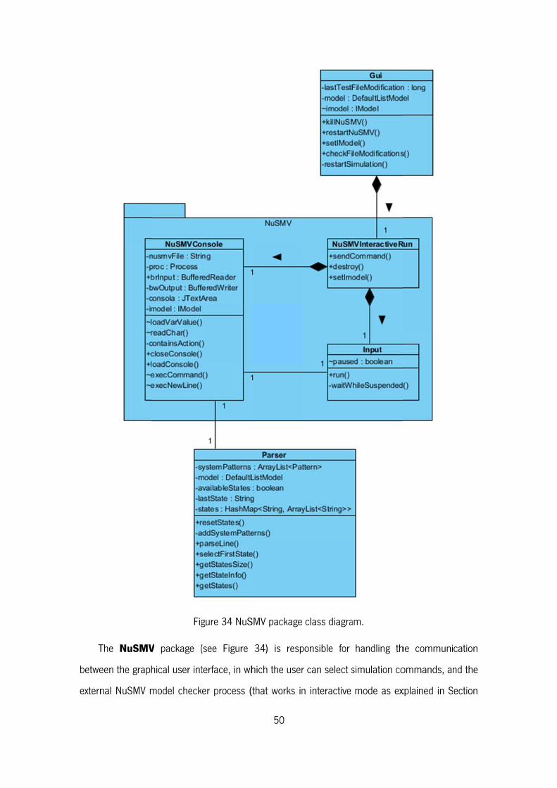
T
betwe
extern
The NuSMV
een the grap
nal NuSMV m
Fig
V package (
hical user int
model check
gure 34 NuS
(see Figure
terface, in wh
ker process (
50
SMV package
34) is resp
hich the user
(that works in
class diagra
ponsible for
r can select s
n interactive
am.
handling th
simulation co
mode as ex
he communi
ommands, an
xplained in S
cation
nd the
ection
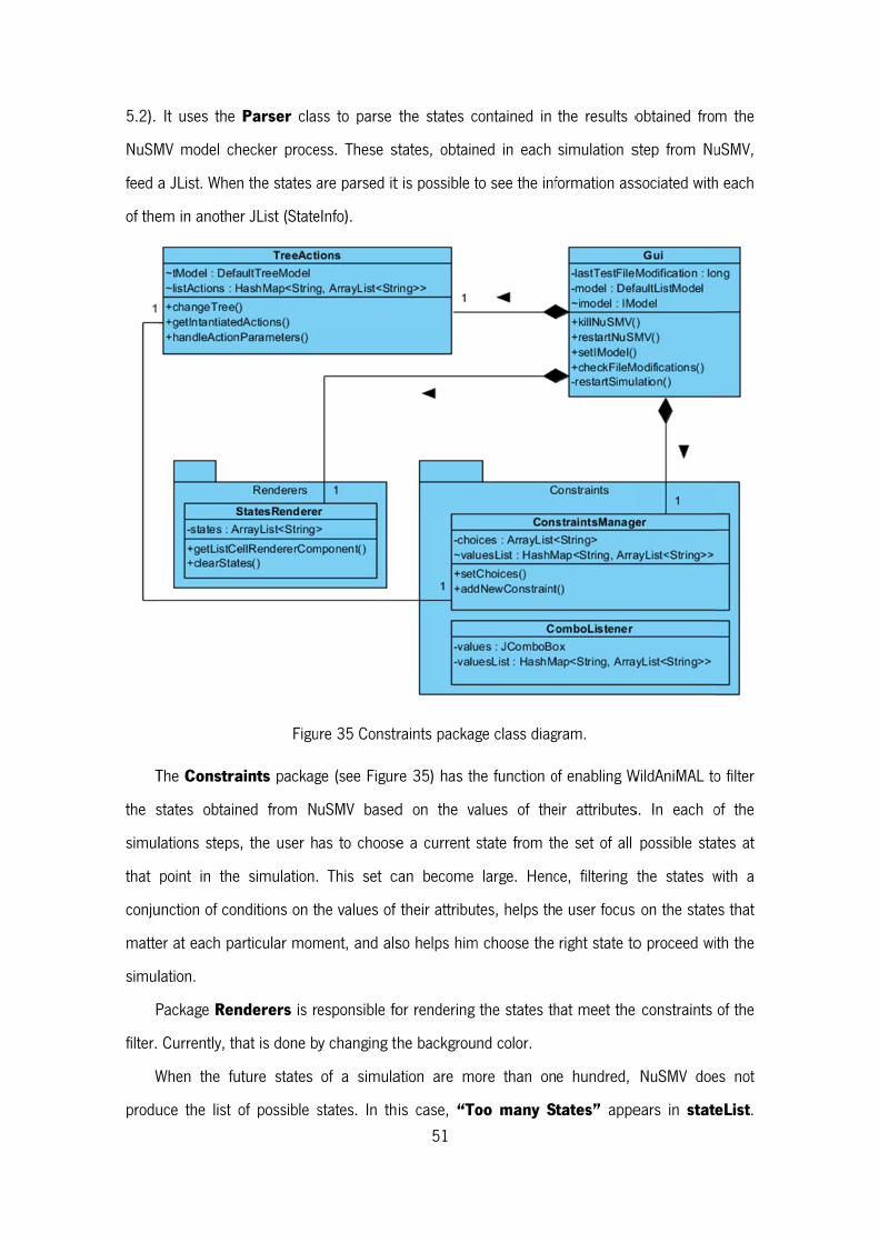
5.2).
NuSM
feed a
of the
T
the s
simul
that
conju
matte
simul
P
filter.
W
produ
It uses the
MV model ch
a JList. When
em in anothe
The Constra
states obtain
lations steps
point in the
unction of con
er at each pa
lation.
Package Ren
Currently, th
When the fu
uce the list
Parser clas
hecker proce
n the states a
er JList (State
Figu
aints packag
ned from N
s, the user h
e simulation.
nditions on t
articular mom
nderers is r
hat is done b
uture states
of possible s
ss to parse
ess. These s
are parsed it
eInfo).
ure 35 Constr
ge (see Figur
uSMV based
as to choose
This set c
he values of
ment, and als
esponsible fo
y changing th
of a simula
states. In th51
the states c
states, obtain
t is possible t
raints packag
re 35) has th
d on the va
e a current s
can become
their attribut
so helps him
or rendering
he backgrou
ation are mo
is case, “To
contained in
ned in each
to see the inf
ge class diag
he function o
alues of the
state from th
large. Henc
tes, helps th
m choose the
the states th
nd color.
ore than on
oo many S
the results o
simulation s
formation ass
gram.
of enabling W
eir attributes
he set of all
ce, filtering
e user focus
right state to
hat meet the
e hundred,
tates” appe
obtained fro
step from Nu
sociated with
WildAniMAL to
s. In each o
possible sta
the states w
on the state
o proceed wi
e constraints
NuSMV doe
ears in stat
m the
uSMV,
h each
o filter
of the
ates at
with a
es that
ith the
of the
es not
eList.
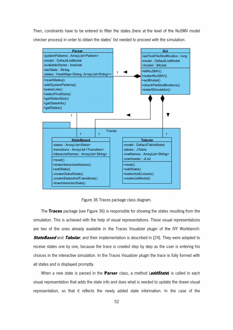
Then
check
T
simul
are tw
State
receiv
choic
all sta
W
visua
repre
, constraints
ker process)
The Traces
lation. This is
wo of the o
teBased and
ve states one
ces in the inte
ates and is d
When a new
l representat
esentation, s
have to be
in order to o
Fi
package (see
s achieved w
ones already
d Tabular, a
e by one, be
eractive simu
isplayed prom
state is par
tion that adds
so that it re
entered to f
btain the sta
gure 36 Trac
e Figure 36)
with the help
available in
nd their imp
ecause the tr
ulation. In th
mptly.
rsed in the P
s the state in
eflects the n
52
filter the stat
ates’ list need
ces package
is responsib
of visual rep
n the Traces
plementation
race is create
e Traces Vis
Parser class
nfo and does
newly added
tes (here at t
ded to procee
class diagra
ble for showin
presentations
s Visualizer
is described
ed step by s
ualizer plugin
s, a method
what is need
d state info
the level of t
ed with the s
m.
ng the states
s. These visu
plugin of the
in [24]. The
tep as the u
n the trace is
(addState)
ded to updat
rmation. In
the NuSMV
simulation.
resulting fro
ual represent
e IVY Workb
ey were adap
ser is enteri
s fully forme
) is called in
te the drawn
the case o
model
om the
tations
bench:
pted to
ng his
d with
n each
visual
of the
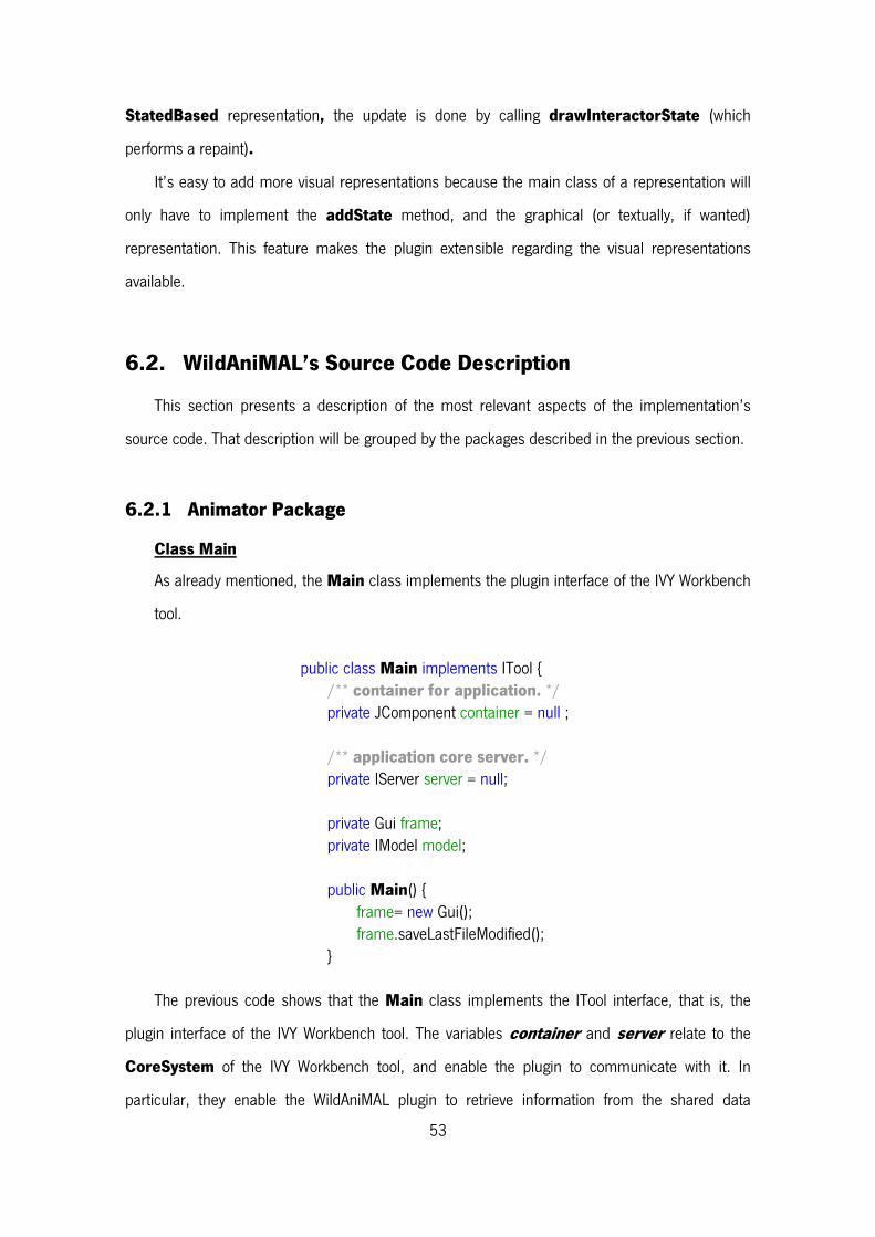
53
StatedBased representation, the update is done by calling drawInteractorState (which
performs a repaint).
It’s easy to add more visual representations because the main class of a representation will
only have to implement the addState method, and the graphical (or textually, if wanted)
representation. This feature makes the plugin extensible regarding the visual representations
available.
6.2. WildAniMAL’s Source Code Description
This section presents a description of the most relevant aspects of the implementation’s
source code. That description will be grouped by the packages described in the previous section.
6.2.1 Animator Package
Class Main
As already mentioned, the Main class implements the plugin interface of the IVY Workbench
tool.
public class Main implements ITool {
/** container for application. */ private JComponent container = null ; /** application core server. */ private IServer server = null; private Gui frame; private IModel model; public Main() {
frame= new Gui(); frame.saveLastFileModified();
}
The previous code shows that the Main class implements the ITool interface, that is, the
plugin interface of the IVY Workbench tool. The variables container and server relate to the
CoreSystem of the IVY Workbench tool, and enable the plugin to communicate with it. In
particular, they enable the WildAniMAL plugin to retrieve information from the shared data
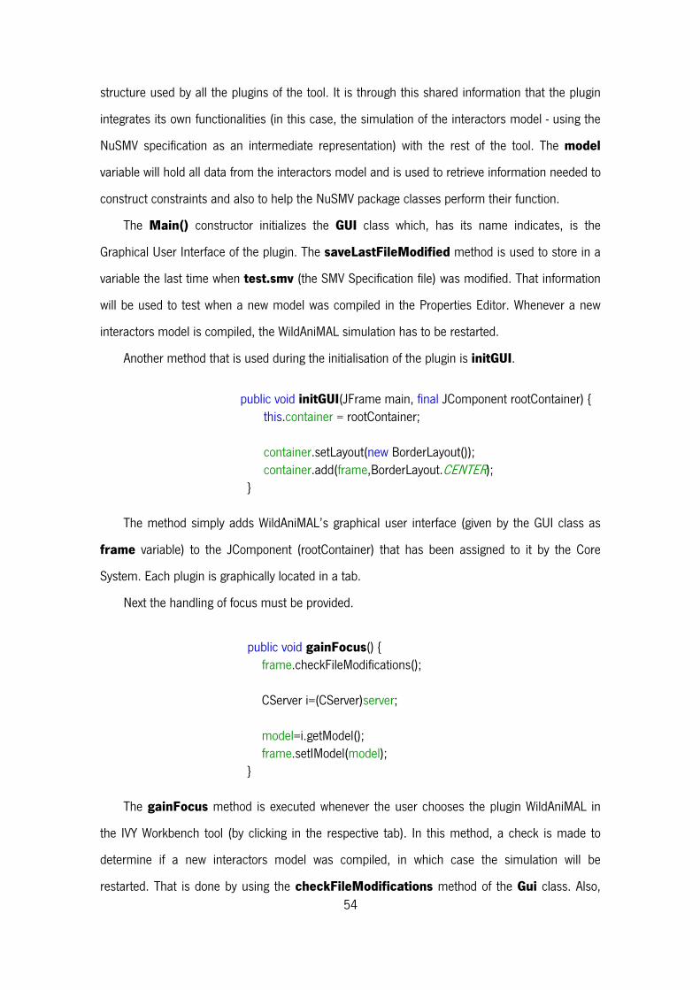
54
structure used by all the plugins of the tool. It is through this shared information that the plugin
integrates its own functionalities (in this case, the simulation of the interactors model - using the
NuSMV specification as an intermediate representation) with the rest of the tool. The model
variable will hold all data from the interactors model and is used to retrieve information needed to
construct constraints and also to help the NuSMV package classes perform their function.
The Main() constructor initializes the GUI class which, has its name indicates, is the
Graphical User Interface of the plugin. The saveLastFileModified method is used to store in a
variable the last time when test.smv (the SMV Specification file) was modified. That information
will be used to test when a new model was compiled in the Properties Editor. Whenever a new
interactors model is compiled, the WildAniMAL simulation has to be restarted.
Another method that is used during the initialisation of the plugin is initGUI.
public void initGUI(JFrame main, final JComponent rootContainer) {
this.container = rootContainer;
container.setLayout(new BorderLayout()); container.add(frame,BorderLayout.CENTER);
}
The method simply adds WildAniMAL’s graphical user interface (given by the GUI class as
frame variable) to the JComponent (rootContainer) that has been assigned to it by the Core
System. Each plugin is graphically located in a tab.
Next the handling of focus must be provided.
public void gainFocus() {
frame.checkFileModifications();
CServer i=(CServer)server;
model=i.getModel(); frame.setIModel(model);
}
The gainFocus method is executed whenever the user chooses the plugin WildAniMAL in
the IVY Workbench tool (by clicking in the respective tab). In this method, a check is made to
determine if a new interactors model was compiled, in which case the simulation will be
restarted. That is done by using the checkFileModifications method of the Gui class. Also,
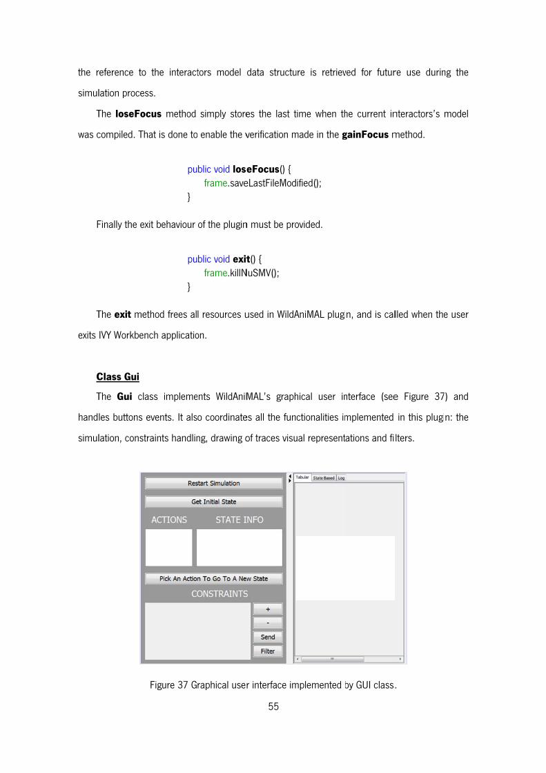
the r
simul
T
was c
F
T
exits
C
T
hand
simul
reference to
lation proces
The loseFoc
compiled. Th
Finally the ex
The exit met
IVY Workben
Class Gui
The Gui cla
les buttons e
lation, constr
the interact
ss.
cus method
at is done to
pu
}
xit behaviour
pu
}
thod frees al
nch applicatio
ass impleme
events. It als
raints handlin
Figure 37 G
tors model
simply store
enable the v
blic void loseframe.save
of the plugin
blic void exitframe.killN
l resources u
on.
ents WildAniM
o coordinate
ng, drawing o
raphical user
55
data structu
es the last t
verification m
eFocus() { eLastFileMod
n must be pro
t() { NuSMV();
used in WildA
MAL’s graph
es all the fun
of traces visu
r interface im
ure is retriev
time when th
made in the g
ified();
ovided.
AniMAL plugi
hical user in
ctionalities im
ual represent
mplemented b
ved for futur
he current in
gainFocus m
n, and is cal
nterface (see
mplemented
ations and fi
by GUI class.
re use durin
nteractors’s
method.
lled when the
e Figure 37
in this plugi
lters.
.
ng the
model
e user
7) and
n: the
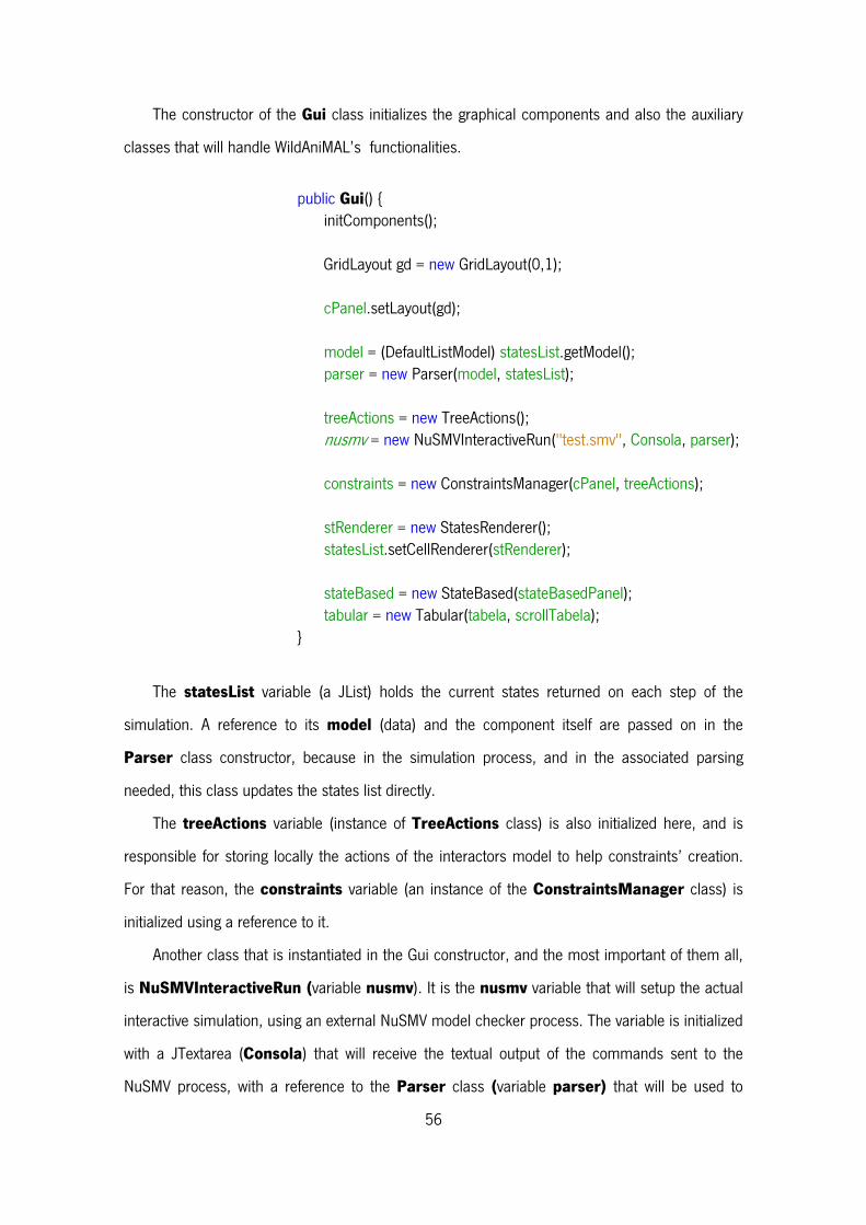
56
The constructor of the Gui class initializes the graphical components and also the auxiliary
classes that will handle WildAniMAL’s functionalities.
public Gui() { initComponents(); GridLayout gd = new GridLayout(0,1);
cPanel.setLayout(gd); model = (DefaultListModel) statesList.getModel(); parser = new Parser(model, statesList); treeActions = new TreeActions(); nusmv = new NuSMVInteractiveRun("test.smv", Consola, parser); constraints = new ConstraintsManager(cPanel, treeActions); stRenderer = new StatesRenderer(); statesList.setCellRenderer(stRenderer); stateBased = new StateBased(stateBasedPanel); tabular = new Tabular(tabela, scrollTabela);
}
The statesList variable (a JList) holds the current states returned on each step of the
simulation. A reference to its model (data) and the component itself are passed on in the
Parser class constructor, because in the simulation process, and in the associated parsing
needed, this class updates the states list directly.
The treeActions variable (instance of TreeActions class) is also initialized here, and is
responsible for storing locally the actions of the interactors model to help constraints’ creation.
For that reason, the constraints variable (an instance of the ConstraintsManager class) is
initialized using a reference to it.
Another class that is instantiated in the Gui constructor, and the most important of them all,
is NuSMVInteractiveRun (variable nusmv). It is the nusmv variable that will setup the actual
interactive simulation, using an external NuSMV model checker process. The variable is initialized
with a JTextarea (Consola) that will receive the textual output of the commands sent to the
NuSMV process, with a reference to the Parser class (variable parser) that will be used to
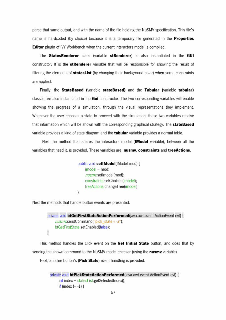
57
parse that same output, and with the name of the file holding the NuSMV specification. This file’s
name is hardcoded (by choice) because it is a temporary file generated in the Properties
Editor plugin of IVY Workbench when the current interactors model is compiled.
The StatesRenderer class (variable stRenderer) is also instantiated in the GUI
constructor. It is the stRenderer variable that will be responsible for showing the result of
filtering the elements of statesList (by changing their background color) when some constraints
are applied.
Finally, the StateBased (variable stateBased) and the Tabular (variable tabular)
classes are also instantiated in the Gui constructor. The two corresponding variables will enable
showing the progress of a simulation, through the visual representations they implement.
Whenever the user chooses a state to proceed with the simulation, these two variables receive
that information which will be shown with the corresponding graphical strategy. The stateBased
variable provides a kind of state diagram and the tabular variable provides a normal table.
Next the method that shares the interactors model (IModel variable), between all the
variables that need it, is provided. These variables are: nusmv, constraints and treeActions.
public void setIModel(IModel mod) {
imodel = mod; nusmv.setImodel(mod); constraints.setChoices(imodel); treeActions.changeTree(imodel);
} Next the methods that handle button events are presented.
private void btGetFirstStateActionPerformed(java.awt.event.ActionEvent evt) {
nusmv.sendCommand("pick_state -i -a"); btGetFirstState.setEnabled(false);
} This method handles the click event on the Get Initial State button, and does that by
sending the shown command to the NuSMV model checker (using the nusmv variable).
Next, another button’s (Pick State) event handling is provided.
private void btPickStateActionPerformed(java.awt.event.ActionEvent evt) { int index = statesList.getSelectedIndex(); if (index != -1) {

58
//Add State to the Trace Visualizer stateBased.addState(""+index, parser.getStateInfo(""+index)); tabular.addState(parser.getStateInfo(""+index)); //SendCommand to show next states if (statesList.getModel().getSize() > 1) nusmv.sendCommand(""+index); model.clear(); nusmv.sendCommand("simulate -i -a -k 1"); stRenderer.clearStates(); //Update Trace Visualization stateBasedPanel.repaint(); tabela.repaint(); interactorsNamesPanel.repaint(); } }
This method picks up the current state choice, that is, the selected number in the
statesList JList. If a choice exists (not null) then the respective state info is added to the traces
visual representations (stateBased and tabular variables). After that, the choice (state number)
is sent to NuSMV model checker and statesList is cleared. Then, the simulate command is
sent to NuSMV which will return states to fill statesList again. Finally repaints are made in order
to show the state update in the trace’s visual representations.
Next the Filter button event handling is provided.
private void filterActionPerformed(java.awt.event.ActionEvent evt) { JPanel constPanel; JComboBox vars, op, vals; String var, opc, val; ArrayList<String> lista = new ArrayList<String>(); for (int i = 0; i < cPanel.getComponentCount(); i++) { constPanel = (JPanel) cPanel.getComponent(i); vars = (JComboBox) constPanel.getComponent(0); op = (JComboBox) constPanel.getComponent(1); vals = (JComboBox) constPanel.getComponent(2); var = (String) vars.getSelectedItem();
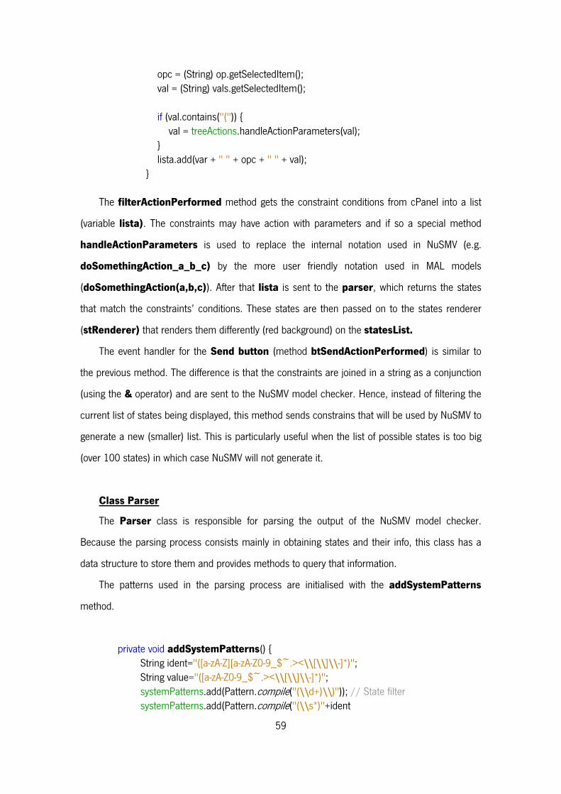
59
opc = (String) op.getSelectedItem(); val = (String) vals.getSelectedItem(); if (val.contains("(")) { val = treeActions.handleActionParameters(val); } lista.add(var + " " + opc + " " + val); }
The filterActionPerformed method gets the constraint conditions from cPanel into a list
(variable lista). The constraints may have action with parameters and if so a special method
handleActionParameters is used to replace the internal notation used in NuSMV (e.g.
doSomethingAction_a_b_c) by the more user friendly notation used in MAL models
(doSomethingAction(a,b,c)). After that lista is sent to the parser, which returns the states
that match the constraints’ conditions. These states are then passed on to the states renderer
(stRenderer) that renders them differently (red background) on the statesList.
The event handler for the Send button (method btSendActionPerformed) is similar to
the previous method. The difference is that the constraints are joined in a string as a conjunction
(using the & operator) and are sent to the NuSMV model checker. Hence, instead of filtering the
current list of states being displayed, this method sends constrains that will be used by NuSMV to
generate a new (smaller) list. This is particularly useful when the list of possible states is too big
(over 100 states) in which case NuSMV will not generate it.
Class Parser
The Parser class is responsible for parsing the output of the NuSMV model checker.
Because the parsing process consists mainly in obtaining states and their info, this class has a
data structure to store them and provides methods to query that information.
The patterns used in the parsing process are initialised with the addSystemPatterns
method.
private void addSystemPatterns() { String ident="([a-zA-Z][a-zA-Z0-9_$~.><\\[\\]\\-]*)"; String value="([a-zA-Z0-9_$~.><\\[\\]\\-]*)"; systemPatterns.add(Pattern.compile("(\\d+)\\)")); // State filter systemPatterns.add(Pattern.compile("(\\s*)"+ident
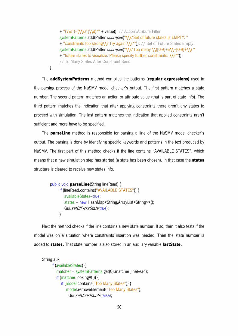
60
+ "(\\s*)=(\\s)*(\\d)*" + value)); // Action\Atribute Filter systemPatterns.add(Pattern.compile("\\s*Set of future states is EMPTY: " + "constraints too strong\\? Try again.\\s*")); // Set of Future States Empty systemPatterns.add(Pattern.compile("\\s*Too many \\([0-9]+e\\+[0-9]+\\) " + "future states to visualize. Please specify further constraints: \\s*")); // To Many States After Constraint Send }
The addSystemPatterns method compiles the patterns (regular expressions) used in
the parsing process of the NuSMV model checker’s output. The first pattern matches a state
number. The second pattern matches an action or attribute value (that is part of state info). The
third pattern matches the indication that after applying constraints there aren’t any states to
proceed with simulation. The last pattern matches the indication that applied constraints aren’t
sufficient and more have to be specified.
The parseLine method is responsible for parsing a line of the NuSMV model checker’s
output. The parsing is done by identifying specific keywords and patterns in the text produced by
NuSMV. The first part of this method checks if the line contains “AVAILABLE STATES”, which
means that a new simulation step has started (a state has been chosen). In that case the states
structure is cleared to receive new states info.
public void parseLine(String lineRead) { if (lineRead.contains("AVAILABLE STATES")) { availableStates=true; states = new HashMap<String,ArrayList<String>>(); Gui.setBtPicksState(true); }
Next the method checks if the line contains a new state number. If so, then it also tests if the
model was on a situation where constraints insertion was needed. Then the state number is
added to states. That state number is also stored in an auxiliary variable lastState.
String aux; if (availableStates) { matcher = systemPatterns.get(0).matcher(lineRead); if (matcher.lookingAt()) { if (model.contains("Too Many States")) { model.removeElement("Too Many States"); Gui.setConstraints(false);
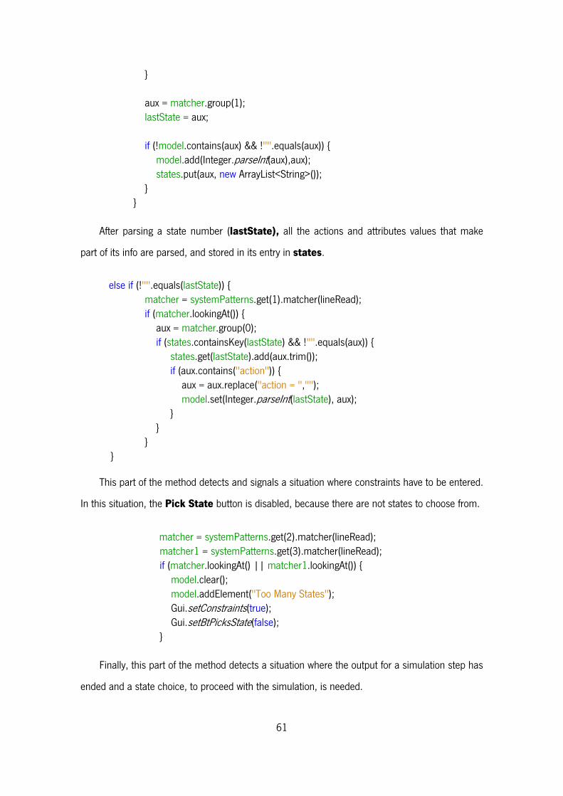
61
} aux = matcher.group(1); lastState = aux; if (!model.contains(aux) && !"".equals(aux)) { model.add(Integer.parseInt(aux),aux); states.put(aux, new ArrayList<String>()); } } After parsing a state number (lastState), all the actions and attributes values that make
part of its info are parsed, and stored in its entry in states.
else if (!"".equals(lastState)) { matcher = systemPatterns.get(1).matcher(lineRead); if (matcher.lookingAt()) { aux = matcher.group(0); if (states.containsKey(lastState) && !"".equals(aux)) { states.get(lastState).add(aux.trim()); if (aux.contains("action")) { aux = aux.replace("action = ",""); model.set(Integer.parseInt(lastState), aux); } } } }
This part of the method detects and signals a situation where constraints have to be entered.
In this situation, the Pick State button is disabled, because there are not states to choose from.
matcher = systemPatterns.get(2).matcher(lineRead); matcher1 = systemPatterns.get(3).matcher(lineRead); if (matcher.lookingAt() || matcher1.lookingAt()) { model.clear(); model.addElement("Too Many States"); Gui.setConstraints(true); Gui.setBtPicksState(false); }
Finally, this part of the method detects a situation where the output for a simulation step has
ended and a state choice, to proceed with the simulation, is needed.
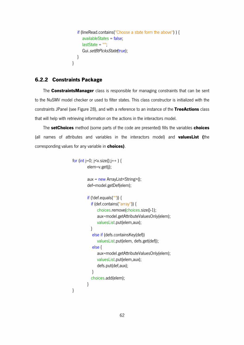
62
if (lineRead.contains("Choose a state form the above") ) { availableStates = false; lastState = ""; Gui.setBtPicksState(true); } }
6.2.2 Constraints Package
The ConstraintsManager class is responsible for managing constraints that can be sent
to the NuSMV model checker or used to filter states. This class constructor is initialized with the
constraints JPanel (see Figure 28), and with a reference to an instance of the TreeActions class
that will help with retrieving information on the actions in the interactors model.
The setChoices method (some parts of the code are presented) fills the variables choices
(all names of attributes and variables in the interactors model) and valuesList (the
corresponding values for any variable in choices).
for (int j=0; j<v.size();j++ ) { elem=v.get(j); aux = new ArrayList<String>(); def=model.getDef(elem); if (!def.equals("")) { if (def.contains("array")) { choices.remove(choices.size()-1); aux=model.getAttributeValuesOnly(elem); valuesList.put(elem,aux); } else if (defs.containsKey(def)) valuesList.put(elem, defs.get(def)); else { aux=model.getAttributeValuesOnly(elem); valuesList.put(elem,aux); defs.put(def,aux); } choices.add(elem); } }
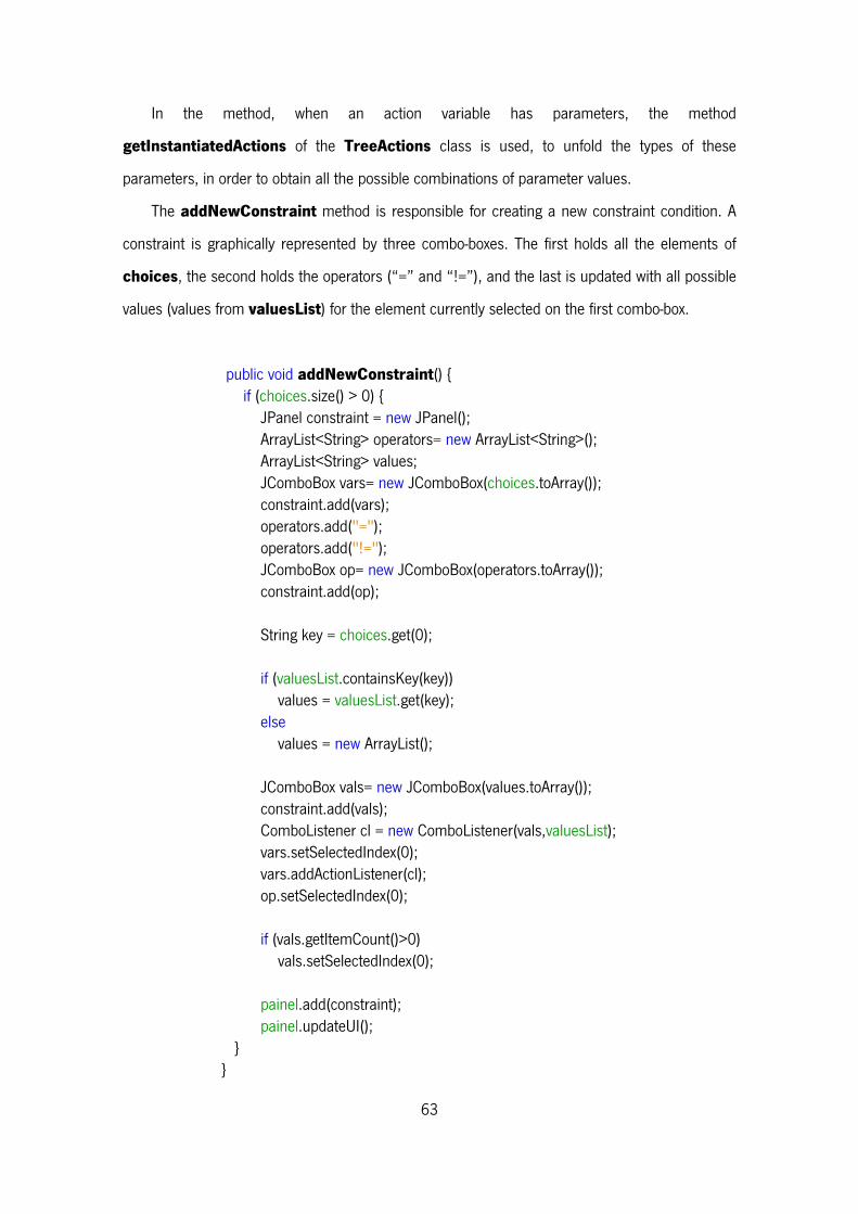
63
In the method, when an action variable has parameters, the method
getInstantiatedActions of the TreeActions class is used, to unfold the types of these
parameters, in order to obtain all the possible combinations of parameter values.
The addNewConstraint method is responsible for creating a new constraint condition. A
constraint is graphically represented by three combo-boxes. The first holds all the elements of
choices, the second holds the operators (“=” and “!=”), and the last is updated with all possible
values (values from valuesList) for the element currently selected on the first combo-box.
public void addNewConstraint() { if (choices.size() > 0) { JPanel constraint = new JPanel(); ArrayList<String> operators= new ArrayList<String>(); ArrayList<String> values; JComboBox vars= new JComboBox(choices.toArray()); constraint.add(vars); operators.add("="); operators.add("!="); JComboBox op= new JComboBox(operators.toArray()); constraint.add(op); String key = choices.get(0); if (valuesList.containsKey(key)) values = valuesList.get(key); else values = new ArrayList(); JComboBox vals= new JComboBox(values.toArray()); constraint.add(vals); ComboListener cl = new ComboListener(vals,valuesList); vars.setSelectedIndex(0); vars.addActionListener(cl); op.setSelectedIndex(0); if (vals.getItemCount()>0) vals.setSelectedIndex(0); painel.add(constraint); painel.updateUI(); } }
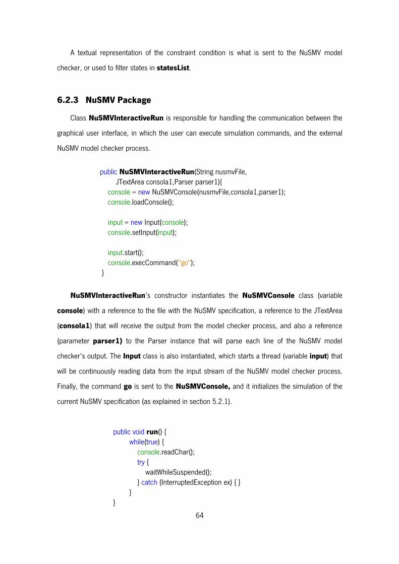
64
A textual representation of the constraint condition is what is sent to the NuSMV model
checker, or used to filter states in statesList.
6.2.3 NuSMV Package
Class NuSMVInteractiveRun is responsible for handling the communication between the
graphical user interface, in which the user can execute simulation commands, and the external
NuSMV model checker process.
public NuSMVInteractiveRun(String nusmvFile, JTextArea consola1,Parser parser1){ console = new NuSMVConsole(nusmvFile,consola1,parser1); console.loadConsole(); input = new Input(console); console.setInput(input); input.start(); console.execCommand("go"); }
NuSMVInteractiveRun’s constructor instantiates the NuSMVConsole class (variable
console) with a reference to the file with the NuSMV specification, a reference to the JTextArea
(consola1) that will receive the output from the model checker process, and also a reference
(parameter parser1) to the Parser instance that will parse each line of the NuSMV model
checker’s output. The Input class is also instantiated, which starts a thread (variable input) that
will be continuously reading data from the input stream of the NuSMV model checker process.
Finally, the command go is sent to the NuSMVConsole, and it initializes the simulation of the
current NuSMV specification (as explained in section 5.2.1).
public void run() { while(true) { console.readChar(); try { waitWhileSuspended(); } catch (InterruptedException ex) { } } }
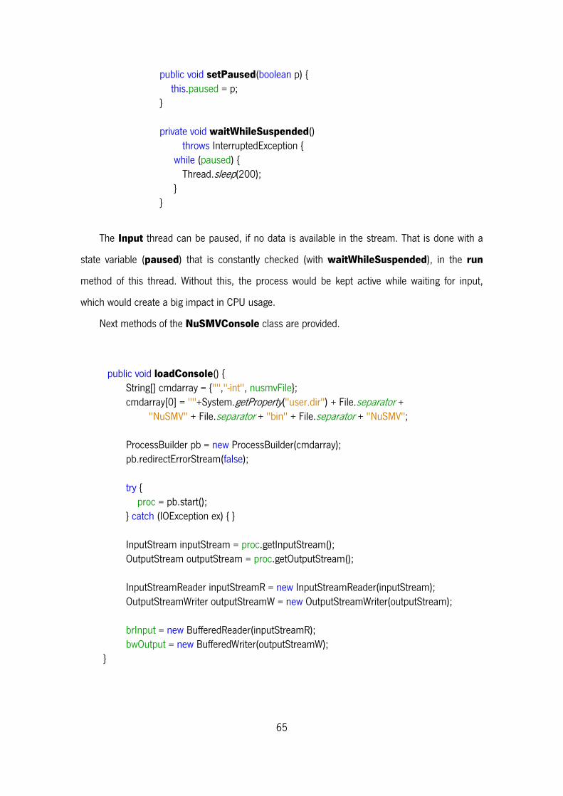
65
public void setPaused(boolean p) { this.paused = p; } private void waitWhileSuspended() throws InterruptedException { while (paused) { Thread.sleep(200); } }
The Input thread can be paused, if no data is available in the stream. That is done with a
state variable (paused) that is constantly checked (with waitWhileSuspended), in the run
method of this thread. Without this, the process would be kept active while waiting for input,
which would create a big impact in CPU usage.
Next methods of the NuSMVConsole class are provided.
public void loadConsole() { String[] cmdarray = {"","-int", nusmvFile}; cmdarray[0] = ""+System.getProperty("user.dir") + File.separator + "NuSMV" + File.separator + "bin" + File.separator + "NuSMV"; ProcessBuilder pb = new ProcessBuilder(cmdarray); pb.redirectErrorStream(false); try { proc = pb.start(); } catch (IOException ex) { } InputStream inputStream = proc.getInputStream(); OutputStream outputStream = proc.getOutputStream(); InputStreamReader inputStreamR = new InputStreamReader(inputStream); OutputStreamWriter outputStreamW = new OutputStreamWriter(outputStream); brInput = new BufferedReader(inputStreamR); bwOutput = new BufferedWriter(outputStreamW); }
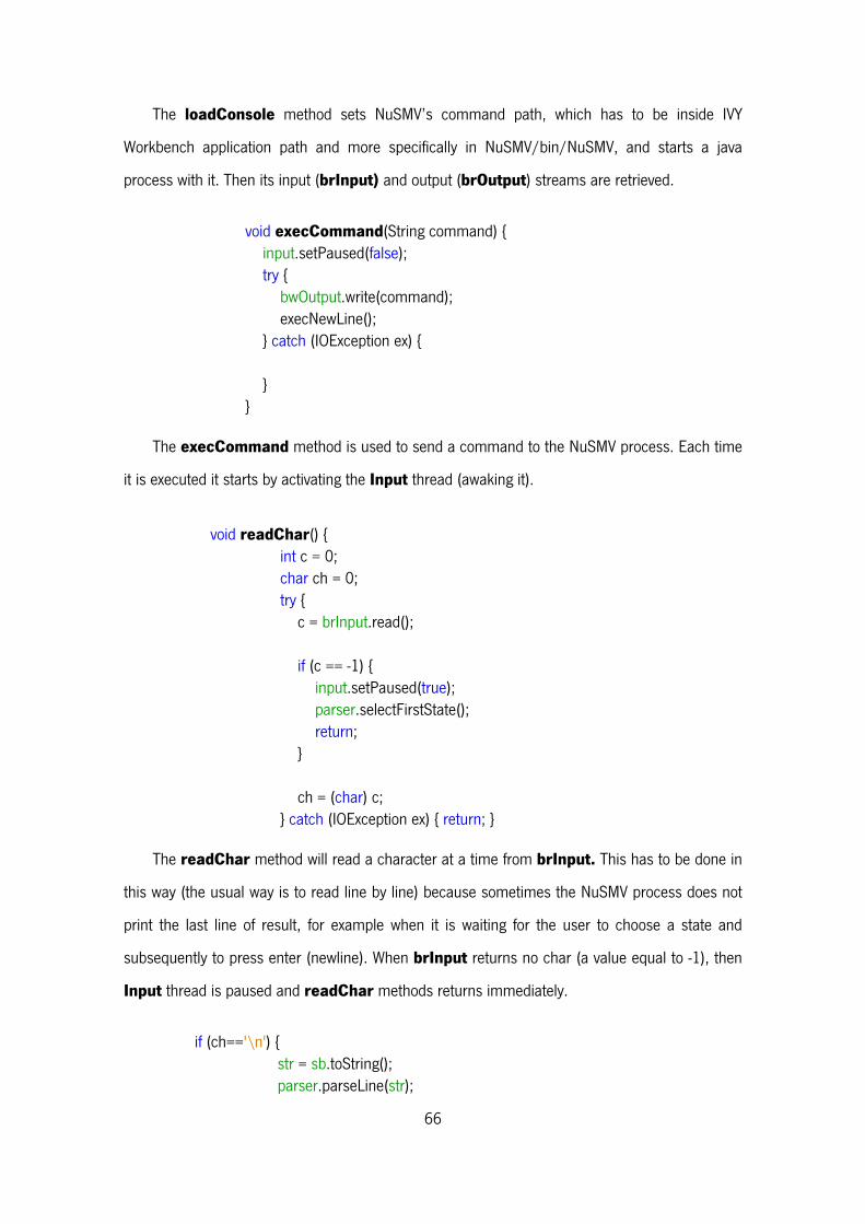
66
The loadConsole method sets NuSMV’s command path, which has to be inside IVY
Workbench application path and more specifically in NuSMV/bin/NuSMV, and starts a java
process with it. Then its input (brInput) and output (brOutput) streams are retrieved.
void execCommand(String command) { input.setPaused(false); try { bwOutput.write(command); execNewLine(); } catch (IOException ex) { } }
The execCommand method is used to send a command to the NuSMV process. Each time
it is executed it starts by activating the Input thread (awaking it).
void readChar() { int c = 0; char ch = 0; try { c = brInput.read(); if (c == -1) { input.setPaused(true); parser.selectFirstState(); return; } ch = (char) c; } catch (IOException ex) { return; }
The readChar method will read a character at a time from brInput. This has to be done in
this way (the usual way is to read line by line) because sometimes the NuSMV process does not
print the last line of result, for example when it is waiting for the user to choose a state and
subsequently to press enter (newline). When brInput returns no char (a value equal to -1), then
Input thread is paused and readChar methods returns immediately.
if (ch=='\n') { str = sb.toString(); parser.parseLine(str);
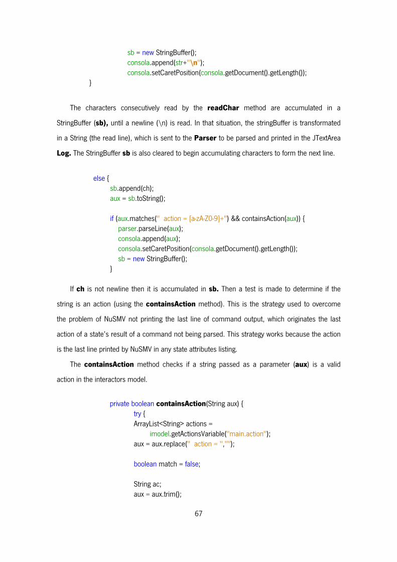
67
sb = new StringBuffer(); consola.append(str+"\n"); consola.setCaretPosition(consola.getDocument().getLength()); }
The characters consecutively read by the readChar method are accumulated in a
StringBuffer (sb), until a newline (\n) is read. In that situation, the stringBuffer is transformated
in a String (the read line), which is sent to the Parser to be parsed and printed in the JTextArea
Log. The StringBuffer sb is also cleared to begin accumulating characters to form the next line.
else { sb.append(ch); aux = sb.toString(); if (aux.matches(" action = [a-zA-Z0-9]+") && containsAction(aux)) { parser.parseLine(aux); consola.append(aux); consola.setCaretPosition(consola.getDocument().getLength()); sb = new StringBuffer(); }
If ch is not newline then it is accumulated in sb. Then a test is made to determine if the
string is an action (using the containsAction method). This is the strategy used to overcome
the problem of NuSMV not printing the last line of command output, which originates the last
action of a state’s result of a command not being parsed. This strategy works because the action
is the last line printed by NuSMV in any state attributes listing.
The containsAction method checks if a string passed as a parameter (aux) is a valid
action in the interactors model.
private boolean containsAction(String aux) { try { ArrayList<String> actions = imodel.getActionsVariable("main.action"); aux = aux.replace(" action = ",""); boolean match = false; String ac; aux = aux.trim();
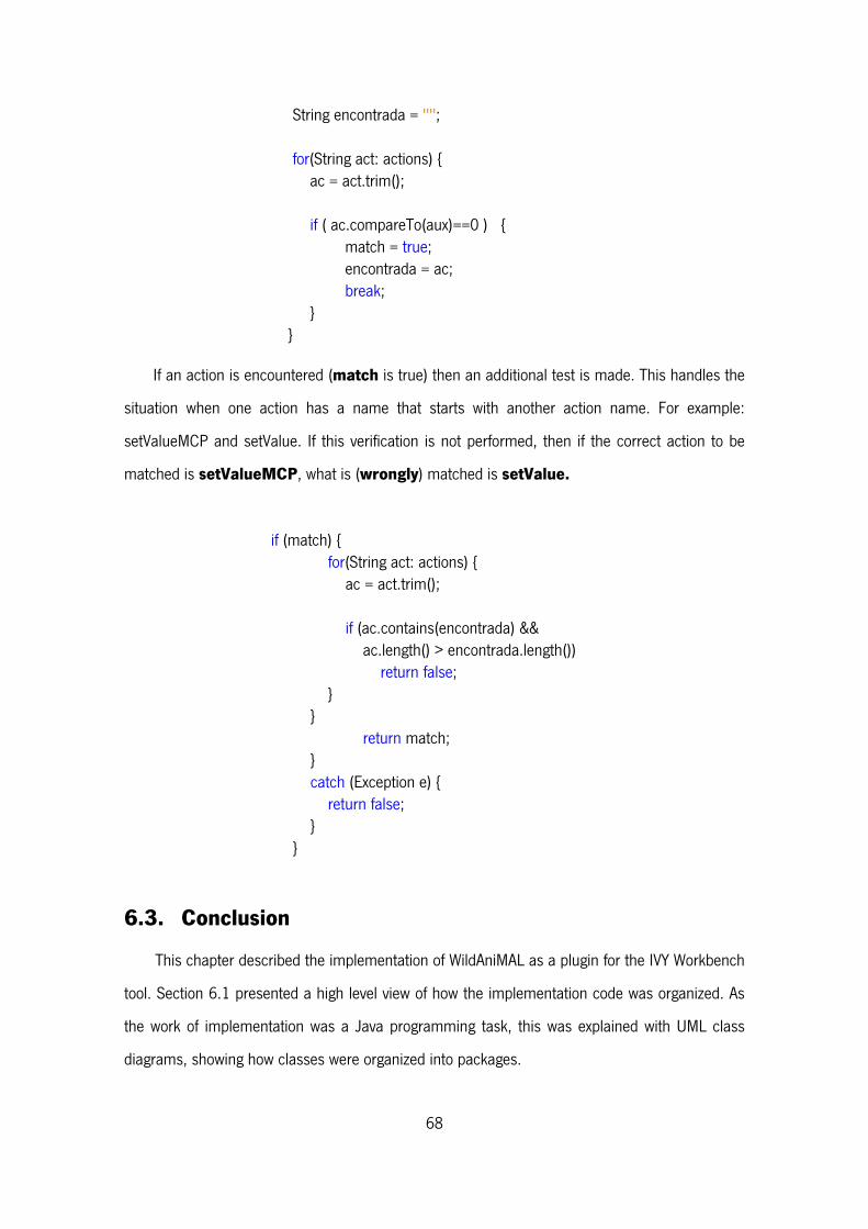
68
String encontrada = ""; for(String act: actions) { ac = act.trim(); if ( ac.compareTo(aux)==0 ) { match = true; encontrada = ac; break; } }
If an action is encountered (match is true) then an additional test is made. This handles the
situation when one action has a name that starts with another action name. For example:
setValueMCP and setValue. If this verification is not performed, then if the correct action to be
matched is setValueMCP, what is (wrongly) matched is setValue.
if (match) { for(String act: actions) { ac = act.trim(); if (ac.contains(encontrada) && ac.length() > encontrada.length()) return false; } } return match; } catch (Exception e) { return false; } }
6.3. Conclusion
This chapter described the implementation of WildAniMAL as a plugin for the IVY Workbench
tool. Section 6.1 presented a high level view of how the implementation code was organized. As
the work of implementation was a Java programming task, this was explained with UML class
diagrams, showing how classes were organized into packages.

69
Section 6.2 makes an extensive explanation of the code. One reason to do that is to fully
present some problems that were encountered during development, and how they were
overcome. By explaining the implementation in detail, it becomes easier for anyone to
understand the code and consequently improve it at a later occasion. This also made it possible
to think about how some implementation choices were made, and in the task of writing the
explanation to describe this code, some methods were implemented in a more efficient way.
70
Chapter 7 – Using WildAniMAL
This chapter demonstrates the WildAniMAL plugin of the IVY Workbench tool. Section 7.1
presents a simulation example that makes extensive use of all the functionalities available in the
plugin. Section 7.2 presents the conclusions of this chapter.
7.1. WildAniMAL’s Usage Example
To explain how the WildAniMAL plugin can be used, a small example of an Ipod-like music
player will be introduced. To be able to keep the explanation short and understandable, some
aspects of the real device will be abstracted in order to work with a simpler model.
First an interactors model of the device will be created using the Model Editor plugin of the
IVY Workbench (see Figure 38).
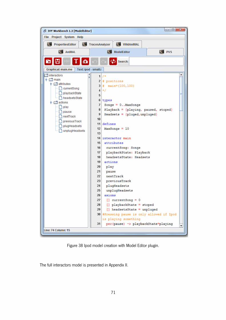
T
The full intera
Figure 38
actors model
8 Ipod model
l is presented
71
l creation wit
d in Appendix
th Model Edit
x II.
tor plugin.
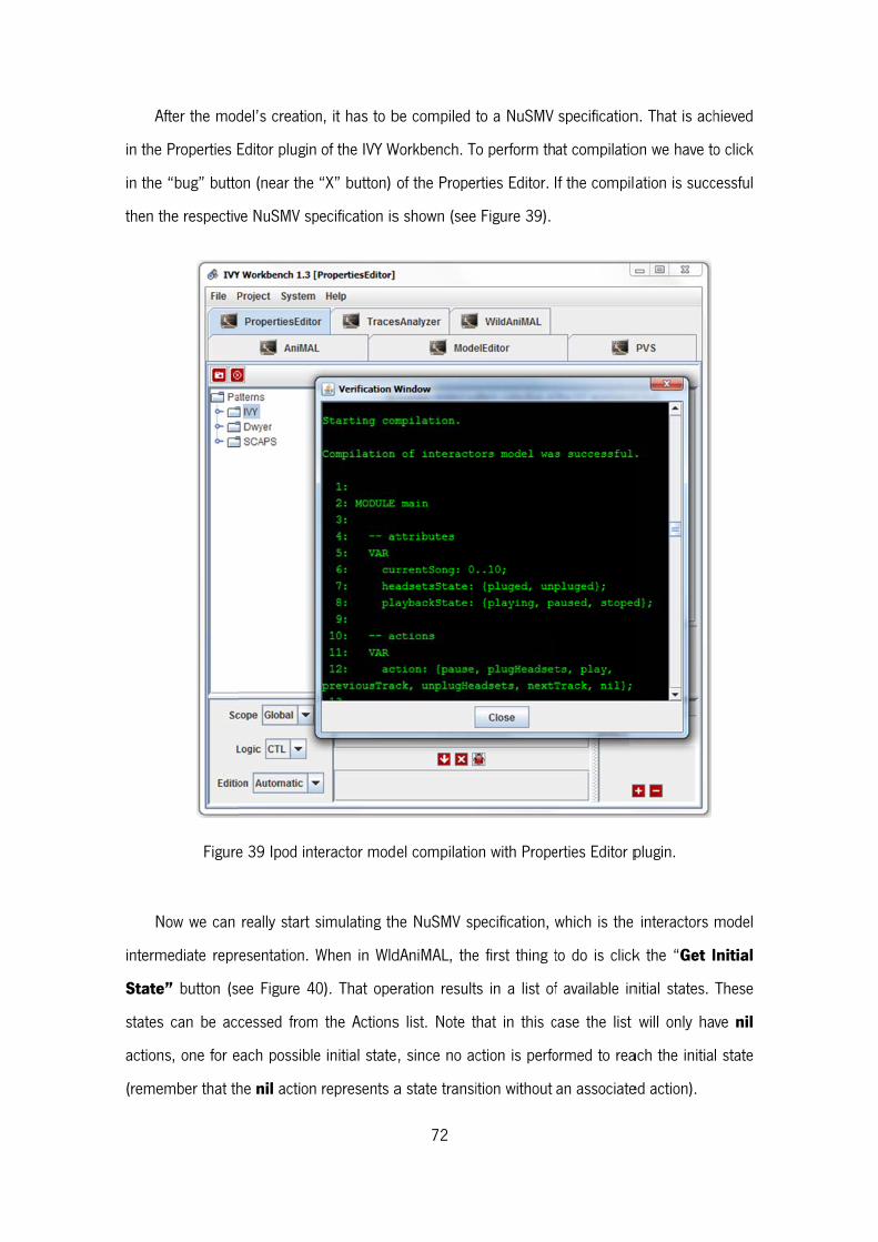
A
in the
in the
then t
N
interm
State
states
action
(reme
After the mod
e Properties E
e “bug” butto
the respectiv
Figure
Now we can
mediate repr
e” button (s
s can be ac
ns, one for e
ember that th
del’s creation
Editor plugin
on (near the
ve NuSMV sp
e 39 Ipod int
really start s
resentation. W
ee Figure 40
cessed from
each possible
he nil action
n, it has to b
of the IVY W
“X” button) o
pecification is
teractor mode
simulating th
When in Wld
0). That ope
the Actions
e initial state
represents a
72
be compiled t
Workbench. T
of the Prope
s shown (see
el compilatio
he NuSMV sp
dAniMAL, the
eration result
s list. Note t
, since no ac
a state transi
to a NuSMV
o perform th
rties Editor.
Figure 39).
on with Prope
pecification, w
e first thing t
s in a list of
hat in this c
ction is perfo
ition without
specification
at compilatio
If the compila
erties Editor p
which is the
to do is click
f available in
case the list
ormed to rea
an associate
n. That is ach
on we have to
ation is succ
plugin.
interactors
k the “Get I
nitial states.
will only ha
ach the initia
ed action).
hieved
o click
cessful
model
Initial
These
ve nil
l state
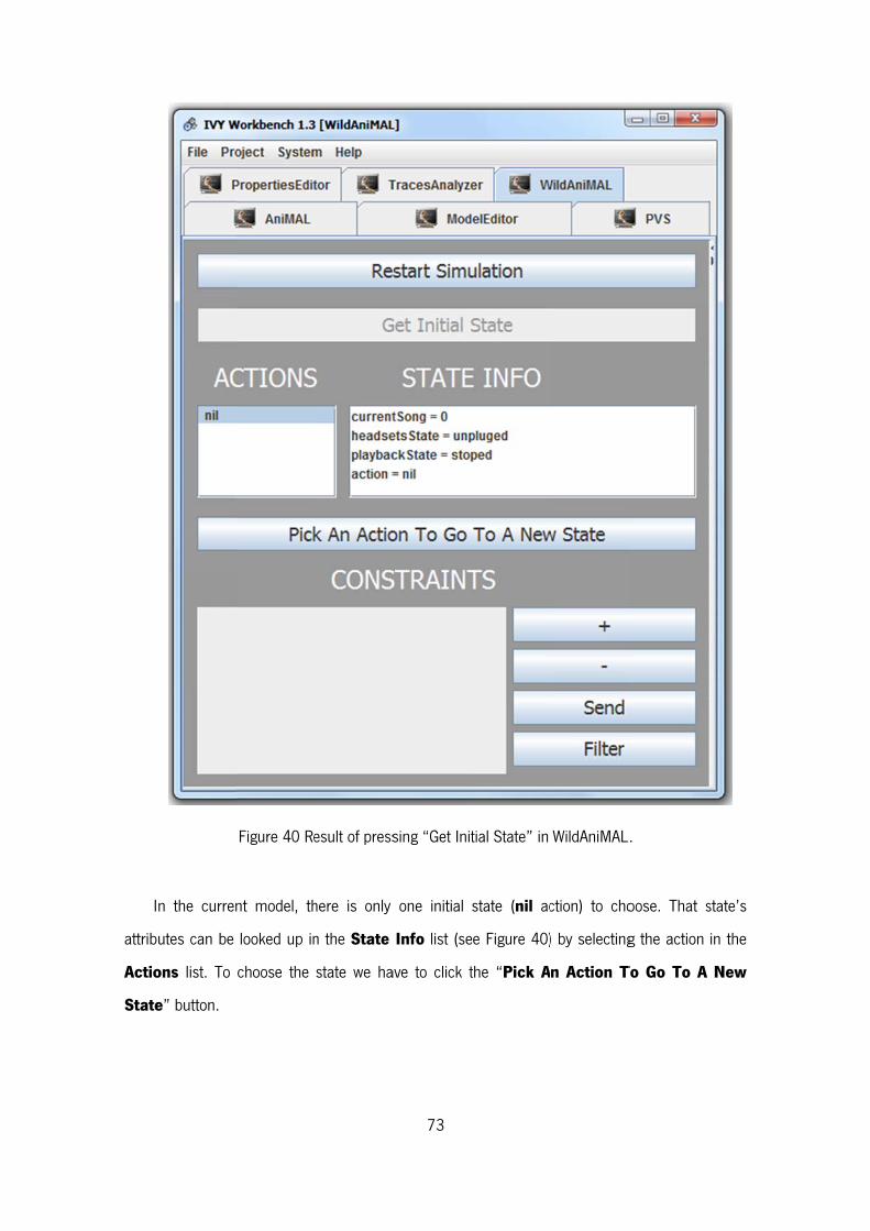
I
attrib
Actio
State
n the curren
utes can be
ons list. To
e” button.
Figure 40 Re
nt model, th
looked up in
choose the
esult of press
here is only
n the State
state we ha
73
sing “Get Init
one initial
Info list (se
ave to click t
tial State” in
state (nil ac
ee Figure 40)
the “Pick A
WildAniMAL
ction) to cho
) by selecting
n Action T
.
oose. That s
g the action
To Go To A
state’s
in the
New
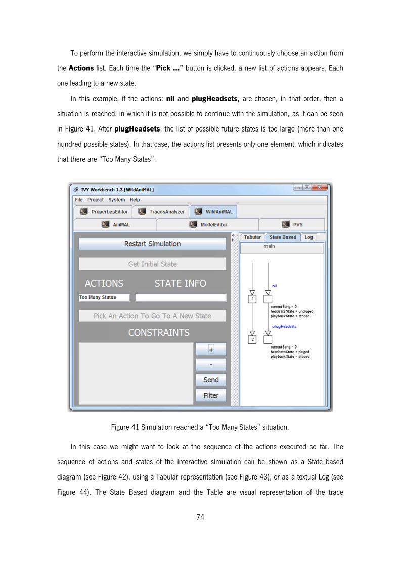
T
the A
one le
I
situat
in Fig
hund
that t
I
seque
diagra
Figure
To perform th
Actions list.
eading to a n
n this exam
tion is reache
gure 41. Afte
red possible
there are “To
n this case
ence of actio
am (see Figu
e 44). The
he interactive
Each time th
new state.
ple, if the ac
ed, in which
er plugHead
states). In th
oo Many State
Figure 41 S
we might w
ons and stat
ure 42), usin
State Based
e simulation,
he “Pick …”
ctions: nil a
it is not pos
dsets, the lis
hat case, the
es”.
Simulation rea
want to look
tes of the in
g a Tabular
d diagram a
74
we simply h
” button is c
and plugHea
ssible to cont
st of possible
e actions list
ached a “Too
at the sequ
nteractive sim
representatio
and the Tab
have to conti
clicked, a new
adsets, are
tinue with the
e future state
presents only
o Many State
uence of the
mulation can
on (see Figur
ble are visua
nuously choo
w list of actio
chosen, in t
e simulation,
es is too larg
y one elemen
es” situation.
actions exe
n be shown
re 43), or as
al representa
ose an action
ons appears.
that order, t
, as it can be
ge (more tha
nt, which ind
ecuted so fa
as a State
a textual Lo
ation of the
n from
. Each
then a
e seen
an one
dicates
r. The
based
g (see
trace
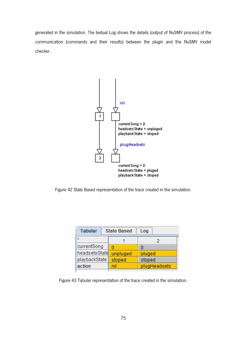
gener
comm
check
rated in the s
munication (
ker.
Figure
Figu
simulation. T
(commands
42 State Ba
re 43 Tabula
The textual L
and their r
sed represen
ar representa
75
Log shows th
results) betw
ntation of the
ation of the tr
e details (ou
ween the pl
e trace create
race created
tput of NuSM
ugin and th
ed in the sim
in the simula
MV process)
he NuSMV
ulation.
ation.
of the
model

I
many
future
done
T
respe
the “S
states
show
n Figure 44,
y futures stat
e states that
as shown in
The constrai
ectively. Whe
Send” butto
s, then a new
wn in Figure 4
Figur
we can see
tes to choos
t NuSMV can
Figure 45.
nts can be
n all constra
on. If the con
w actions list
46.
re 44 Log rep
that the cur
se from (mor
n handle). In
created usi
aints are crea
nstraints are
is available t
76
presentation
rrent simulati
re than one
n this case,
ng the + an
ated, they ar
successful i
to continue t
of the simul
on reached a
hundred, tha
constrains h
nd – button
re sent to the
n the job of
the simulatio
ation.
a situation w
at is the max
ave to be en
s, to add a
e NuSMV mo
reducing the
n. That is th
where there a
ximum num
ntered and t
and remove
odel checker
e number of
he current ca
are too
ber of
that is
them,
using
future
ase, as
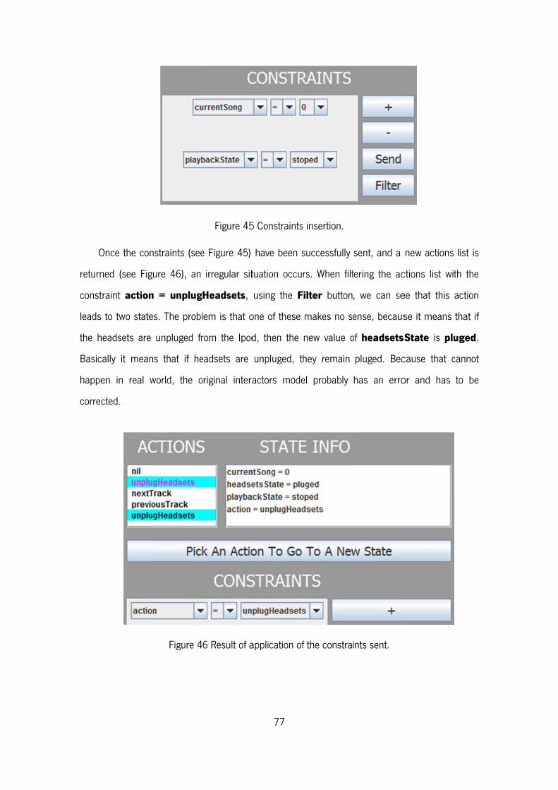
O
return
const
leads
the h
Basic
happe
corre
Once the con
ned (see Fig
traint action
s to two state
headsets are
cally it mean
en in real w
cted.
nstraints (see
gure 46), an
n = unplug
es. The prob
unpluged fr
ns that if he
world, the o
Figure 4
Figure 45
e Figure 45)
irregular sit
gHeadsets,
lem is that o
rom the Ipod
eadsets are
original intera
46 Result of a
77
5 Constraints
have been s
tuation occu
using the F
one of these
d, then the
unpluged, t
actors mode
application of
s insertion.
successfully
rs. When filt
Filter button
makes no se
new value o
hey remain
el probably
f the constra
sent, and a
tering the ac
, we can se
ense, becaus
of headsets
pluged. Bec
has an erro
ints sent.
new actions
ctions list wi
ee that this
se it means
sState is plu
cause that c
or and has
list is
th the
action
that if
uged.
cannot
to be
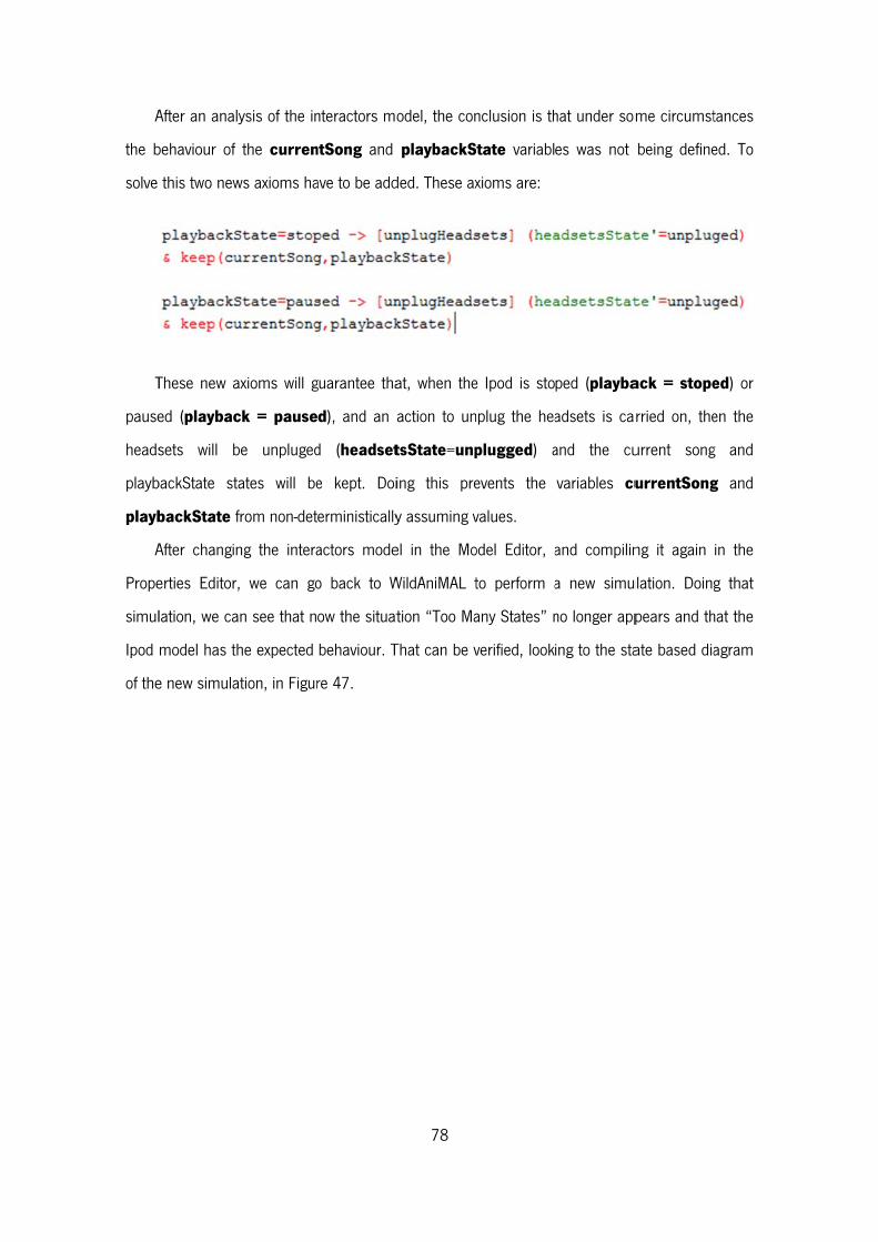
A
the b
solve
T
pause
heads
playb
playb
A
Prope
simul
Ipod
of the
After an anal
behaviour of
this two new
These new a
ed (playbac
sets will b
backState st
backState f
After changin
erties Editor,
lation, we ca
model has th
e new simula
ysis of the in
the curren
ws axioms ha
axioms will g
ck = pause
be unpluged
ates will be
from non-det
ng the intera
, we can go
an see that n
he expected
ation, in Figur
nteractors mo
ntSong and
ave to be add
guarantee tha
d), and an a
d (headset
e kept. Doi
erministically
actors mode
o back to W
ow the situat
behaviour. T
re 47.
78
odel, the con
playbackS
ded. These ax
at, when the
action to un
tsState=unp
ing this pre
y assuming v
el in the Mo
WildAniMAL t
tion “Too Ma
That can be v
nclusion is th
State variabl
xioms are:
e Ipod is sto
nplug the hea
plugged) a
events the
values.
odel Editor, a
to perform a
any States” n
verified, look
hat under som
es was not
ped (playba
adsets is ca
and the cu
variables cu
and compilin
a new simu
no longer app
ing to the sta
me circumst
being define
ack = stope
rried on, the
urrent song
urrentSong
ng it again
ulation. Doing
pears and th
ate based dia
tances
ed. To
ed) or
en the
g and
g and
in the
g that
hat the
agram
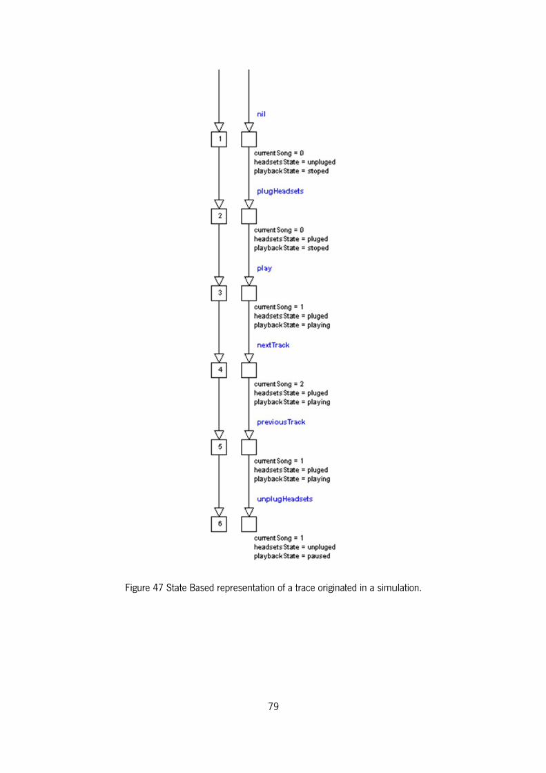
Figure
e 47 State Baased represe
79
entation of a t
trace originatted in a simuulation.

80
7.2. Conclusion
This chapter presented an interactors model of an Ipod-like device. It was shown how that
model can be created, compiled to a NuSMV specification and simulated with WildAniMAL.
We demonstrated how WildAniMAL can be useful in the task of detecting bugs and errors in
an interactive manner. The situation (error in the model) that was presented and corrected was
representative of other similar situations that can occur in other models.
What is important to retain is that we can easily validate an interactors model and see if it
behaves how we expect it too. If that does not happen, then we can use WildAniMAL
functionalities to find out why. Doing this early validation is useful, because we can construct the
interactors model incrementally by validating some steps at a time, instead of creating the big
model and verify it as one.
81
Chapter 8 – Conclusions and
Future Work
This chapter summarizes the work done and all results achieved. Some future work can be
done in order to improve this WildAniMAL plugin, and therefore the aspects that can be worked
on are also presented.
8.1. Goal
The goal of this work was to develop a plugin to help an IVY Workbench user while creating
an interators model to interactively explore its behaviour: that is, enable the user to manually
trigger events and observe how the model evolves. WildAniMAL (Watch It vaLiDation Animator for
MAL) can perform this. It assists the modelling and analysis process, by providing functionalities
to simulate and validate the model being created.
8.2. Results
In order to implement the plugin, three possibilities were studied (see Chapter 5):
a. representing a MAL interactors model as a Finite State Machine (FSM) and use that to
drive the animation;
b. use the BDD (Binary Decision Diagrams) representation of the MAL interactors model,
created by the NuSMV model checker, to perform the animation;
c. use the NuSMV model checker simulations commands, available on its interactive mode,
to perform the animation.
82
After an analysis of the different alternatives it was decided to use the NuSMV’s simulation
capabilities in the implementation of WildAniMAL. The implementation is described in Chapter 6.
The implemented plugin supports the animation of models as intended. At each step the
user can select one of the available actions and the animator presents the state (or possible
states, in case of non-determinism) resulting from that action.
During the process of implementing the plugin, problems related to existence of non-
determinism in the models arose. These related both to NuSMV not generating the list of possible
future states, after a transition, if the number of states in the list exceeds one hundred, and also
because even if the list of possible states is less than one hundred, it might be too large for a
human user to analyse it. These issues were solved with the introduction of constraints to delimit
the effect of actions in the state of the system, and thus reduce non-determinism in the
simulation.
A first result of this dissertation is that the goal of this work, recalled in the previous Section,
has been achieved as is demonstrated by the example presented in Chapter 7.
A parallel result of the work, that is not apparent in the thesis, but is nevertheless important
for the IVY workbench development project, was the improvement of the existing plugins. When
implementing the WildAniMAL plugin, some parts of the code of the CoreSystem and of its
plugins were improved, and now more efficient data structures are used. The tool was developed
in 2006 and since then many developments and changes were introduced in the Java language.
Two examples of it, relating to data structures, are the use of ArrayLists instead of Vectors, and
HashSets instead of HashMaps. Also, when detected, some parts of the code were rewritten, to
be more easily understood or simply because minor bugs could happen as the code had some
minor faults. Other times the improvement was to clear code, as some redundancy was present.
Another result achieved is that the IVY Workbench was extensively tested, because that was
needed to test the WildAniMAL’s implementation and usage. That enabled the detection of some
situations when it did not work as expected, and demanded a need to correct the interoperability
of all the plugins and the CoreSystem of the tool. That was done. Developing WildAniMAL also
enabled us to think about how the functionalities were initially implemented and how they could
be improved. This is specifically true in some aspects of usability.
83
Another important result is that WildAniMAL implementation was fully documented, because
UML diagrams were created that describe its architecture and also because a detailed code
explanation was carried out. This results leads the way to its future improvement, as enables any
person to, relatively easily, understand its implementation and, if desired, improve its
functionalities and source code.
8.3. Future Work
As future work, a more efficient (or automatic) integration of the WildAniMAL plugin in the IVY
Worbench can be performed. Some steps of using it, require the use of other plugins of the IVY
Workbench tool. The use of the Model Editor plugin is obviously a requirement to build the
models, but using Properties Editor to compile the model created in the Model Editor should be
avoided. The user has to go there only to push a button to compile the model. That task can be
automated, but needs some changes in the CoreSystem, so that the compiler might be globally
available in the system.
Additionally work can be carried out in testing WildAniMAL with more examples. One way to
achieve this is to make it available to the Model Checking scientific community, so that different
people might benefit from its capabilities, and also contribute with their feedback to improve tool.
For example, suggesting improvements and new functionalities.
84
References
[1] E. M. Clarke, E. A. Emerson and A. P. Sistla, “Automatic verification of finite-state concurrent
systems using temporal logic specifications,” ACM Trans. Program. Lang. Syst., vol. 8, pp.
244-263, 1986.
[2] F. Paternó, “Design, Specification and Verification of Interactive Systems'94,” Proceedings
of the First International Eurographics Workshop, 8-10 June 1994.
[3] J. Campos and M. Harrison, “Model checking interactor specifications,” Automated Software
Engineering, vol. 8, pp. 275-310, 2001.
[4] K. Loer e M. Harrison, A framework and supporting tool for the model-based analysis for
dependable interactive systems in the context of industrial design, 2004.
[5] K. L. McMillan, Symbolic model checking, Kluwer Academic Publ, 1993.
[6] A. Cimatti, E. Clarke, F. Giunchiglia and M. Roveri, “NuSMV: a new Symbolic Model Verifier,”
in Proceedings Eleventh Conference on Computer-Aided Verfication (CAV'99), Trento, Italy,
1999.
[7] J. C. Campos and M. Harrison, “Systematic analysis of control panel interfaces using formal
tools,” XVth International Workshop on the Design, Verification and Specfication of
Interactive Systems (DSV-IS 2008), pp. 72-85.
[8] J. Campos and M. Harrison, “Modelling and analysing the interactive behaviour of an
infusion pump,” in Electronic Communications of the EASST 45: Fourth International
Workshop on Formal Methods for Interactive Systems (FMIS 2011), 2011.
[9] E. M. Clarke, “The Birth of Model Checking,” in 25 Years of Model Checking, O. a. V. H.
Grumberg, Ed., Berlin, Heidelberg, Springer-Verlag, 2008, pp. 1-26.
[10] J. R. Burch, E. M. Clarke, K. L. McMillan, D. L. Dill and J. Hwang, “Symbolic model
85
checking: 1020 states and beyond,” in Proceedings 5th Annual Symposium on Logic in
Computational Science, 1990.
[11] A. Cimatti, E. Clarke, F. Giunchiglia and M. Roveri, “NuSMV: a new symbolic model
checker,” International Journal on Software Tools for Technology Transfer (STTT),, 2(4)
March 2000.
[12] R. Cavada, A. Cimatti, C. A. Jochim, G. Keighren, E. Olivetti, M. Pistore, R. M. e A. Tchaltsev,
NuSMV 2.5 User Manual, 2010.
[13] R. Cavada, A. Cimatti, C. A. Jochim, G. Keighren, E. Olivetti, M. Pistore, R. M. e A. Tchaltsev,
NuSMV 2.5 Tutorial, 2010.
[14] D. R. Wright, “Finite State Machines,” 2005. [Online]. Available:
http://www4.ncsu.edu/~drwrigh3/docs/courses/csc216/fsm-notes.pdf. [Acedido em 25
October 2012].
[15] A. Gill, Introduction to the theory of finite-state machines, McGraw-Hill, 1962.
[16] S. B. Akers, “Binary Decision Diagrams,” IEEE Trans. Computers 27, vol. 6, n.º 509-516,
1978.
[17] H. R. Andersen, An Introduction to Binary Decision Diagrams, IT University of Copenhagen,
1999.
[18] R. E. Bryant, “Symbolic Boolean Manipulation with Ordered Binary Decision Diagrams,”
ACM Computing Surveys, vol. 24, pp. 293-318, September 1992.
[19] D. J. a. H. M. D. Duke, “Abstract interaction objects,” Comput. Graph. Forum 12, vol. 3, pp.
25-36, 1993.
[20] M. Ryan, J. Fiadeiro e T. Maibaum, “Sharing actions and attributes in modal action logic,”
Theoretical Aspects of Computer Software, pp. 569-593, 1991.
[21] E. Clarke, O. Grumberg e D. Peled, Model Checking, MIT Press, 1999.
[22] Group, Object Management, Unified Modeling Language: Superstructure version 2.0, 2005.
[23] J. C. Campos, J. Machado e E. Seabra, “Property patterns for the formal verification of
automated production systems,” pp. 5107-5112, 2008.
[24] N. M. E. Sousa and J. C. Campos, “Um visualizador de tracos de comportamento para a
86
ferramenta ivy. IVY Technical Report IVY-TR-5-03,” October 2006.
[25] G. Mori, F. Paternò and C. Santoro, “CTTE: support for developing and analyzing task
models for interactive system design,” Transactions on Software Engineering archive, vol. 28
Issue 8, August 2002.
[26] F. Paternó, Model-Based Design and Evaluation of Interactive Applications, Springer, 2000.
[27] F. Paternó, “Task models in interactive software systems,” Handbook of Software
Engineering and Knowledge Engineering, 2001.
[28] D. Paquette, Simulating task models using concrete user interface components, 2004.
[29] N. Guerreiro, S. Mendes, V. Pinheiro e J. C. Campos, “Animal - a user interface prototyper
and animator for mal interactor models,” Interação 2008 - Actas da 3a. Conferência
Nacional em Interação Pessoa-Máquina, pp. 93-102, 2008.
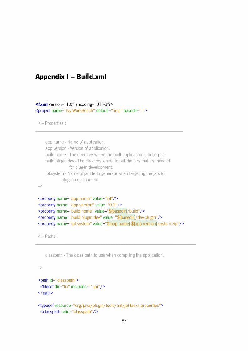
87
Appendix I – Build.xml
<?xml version="1.0" encoding="UTF-8"?> <project name="Ivy WorkBench" default="help" basedir="."> <!-- Properties : ___________________________________________________________ app.name - Name of application. app.version - Version of application. build.home - The directory where the built application is to be put. build.plugin.dev - The directory where to put the jars that are needed for plug-in development. ipf.system - Name of jar file to generate when targeting the jars for plug-in development. --> <property name="app.name" value="ipf"/> <property name="app.version" value="0.1"/> <property name="build.home" value="${basedir}/build"/> <property name="build.plugin.dev" value="${basedir}/dev-plugin"/> <property name="ipf.system" value="${app.name}-${app.version}-system.zip"/> <!-- Paths : ________________________________________________________________ classpath - The class path to use when compiling the application. --> <path id="classpath"> <fileset dir="lib" includes="*.jar"/> </path> <typedef resource="org/java/plugin/tools/ant/jpf-tasks.properties"> <classpath refid="classpath"/>
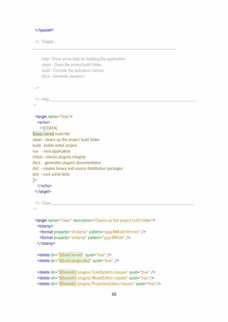
88
</typedef> <!-- Targets : ______________________________________________________________ help - Show some help on building the application. clean - Clean the proect build folder. build - Compile the aplication classes. docs - Generate Javadocs. --> <!-- Help _______________________________________________________________ --> <target name="help"> <echo> <![CDATA[ ${app.name} build file: clean - cleans up the project build folder build - builds entire project run - runs application check - checks plug-ins integrity docs - generates plug-ins documentation dist - creates binary and source distribution packages test - runs some tests ]]> </echo> </target> <!-- Clean ______________________________________________________________ --> <target name="clean" description="Cleans up the project build folder"> <tstamp> <format property="dt-stamp" pattern="yyyy-MM-dd-HH-mm" /> <format property="d-stamp" pattern="yyyy-MM-dd" /> </tstamp> <delete dir="${build.home}" quiet="true" /> <delete dir="${build.plugin.dev}" quiet="true" /> <delete dir="${basedir}/plugins/CoreSystem/classes" quiet="true" /> <delete dir="${basedir}/plugins/ModelEditor/classes" quiet="true"/> <delete dir="${basedir}/plugins/PropertiesEditor/classes" quiet="true"/>
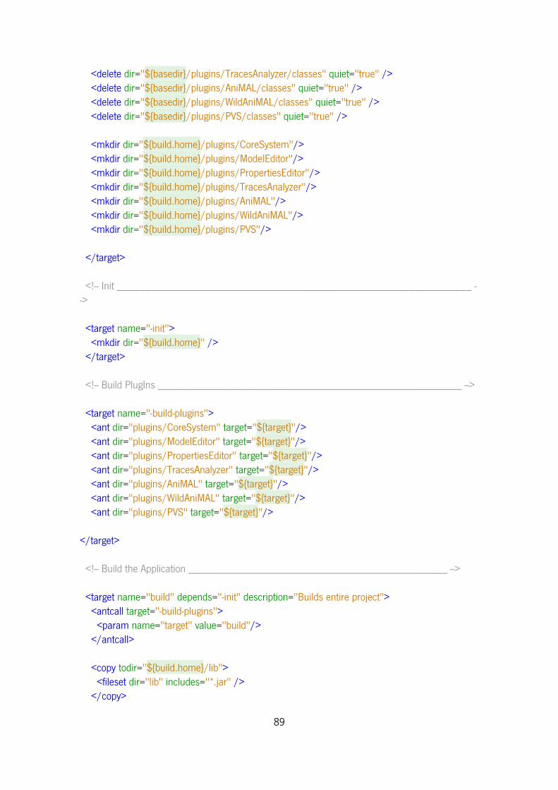
89
<delete dir="${basedir}/plugins/TracesAnalyzer/classes" quiet="true" /> <delete dir="${basedir}/plugins/AniMAL/classes" quiet="true" /> <delete dir="${basedir}/plugins/WildAniMAL/classes" quiet="true" /> <delete dir="${basedir}/plugins/PVS/classes" quiet="true" /> <mkdir dir="${build.home}/plugins/CoreSystem"/> <mkdir dir="${build.home}/plugins/ModelEditor"/> <mkdir dir="${build.home}/plugins/PropertiesEditor"/> <mkdir dir="${build.home}/plugins/TracesAnalyzer"/> <mkdir dir="${build.home}/plugins/AniMAL"/> <mkdir dir="${build.home}/plugins/WildAniMAL"/> <mkdir dir="${build.home}/plugins/PVS"/> </target> <!-- Init _______________________________________________________________ --> <target name="-init"> <mkdir dir="${build.home}" /> </target> <!-- Build PlugIns ______________________________________________________ --> <target name="-build-plugins"> <ant dir="plugins/CoreSystem" target="${target}"/> <ant dir="plugins/ModelEditor" target="${target}"/> <ant dir="plugins/PropertiesEditor" target="${target}"/> <ant dir="plugins/TracesAnalyzer" target="${target}"/> <ant dir="plugins/AniMAL" target="${target}"/> <ant dir="plugins/WildAniMAL" target="${target}"/> <ant dir="plugins/PVS" target="${target}"/> </target> <!-- Build the Application ______________________________________________ --> <target name="build" depends="-init" description="Builds entire project"> <antcall target="-build-plugins"> <param name="target" value="build"/> </antcall> <copy todir="${build.home}/lib"> <fileset dir="lib" includes="*.jar" /> </copy>
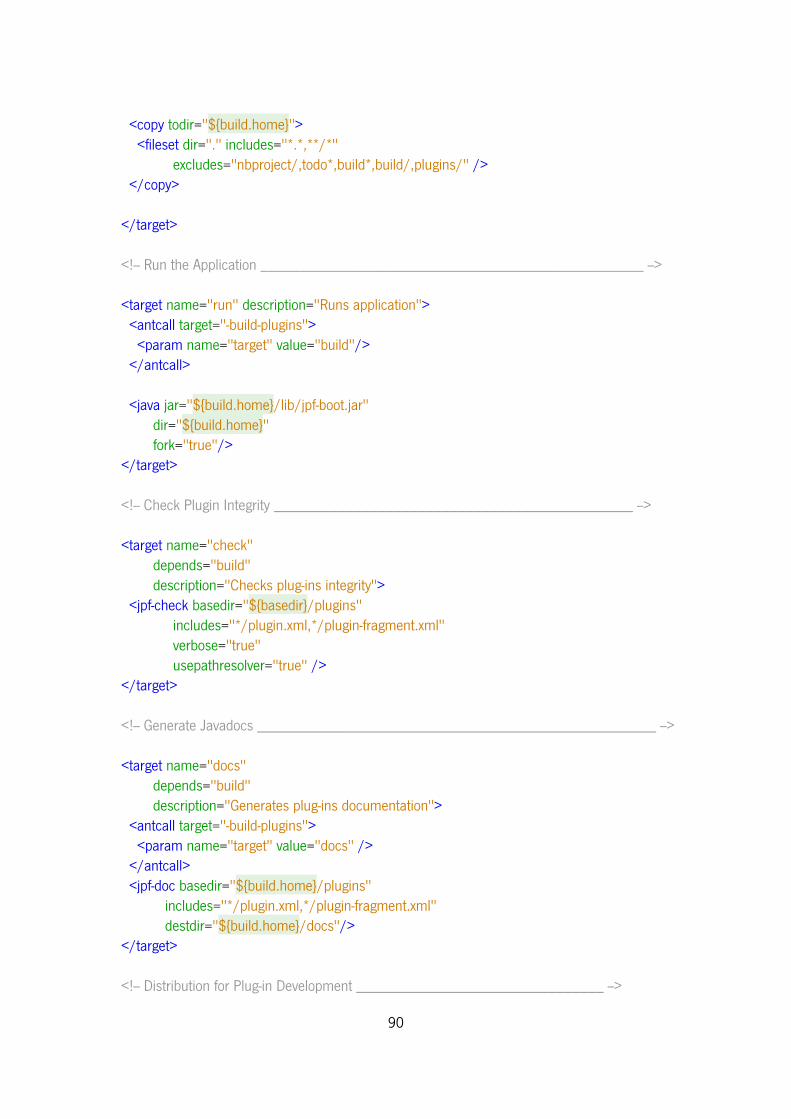
90
<copy todir="${build.home}"> <fileset dir="." includes="*.*,**/*" excludes="nbproject/,todo*,build*,build/,plugins/" /> </copy> </target> <!-- Run the Application ________________________________________________ --> <target name="run" description="Runs application"> <antcall target="-build-plugins"> <param name="target" value="build"/> </antcall> <java jar="${build.home}/lib/jpf-boot.jar" dir="${build.home}" fork="true"/> </target> <!-- Check Plugin Integrity _____________________________________________ --> <target name="check" depends="build" description="Checks plug-ins integrity"> <jpf-check basedir="${basedir}/plugins" includes="*/plugin.xml,*/plugin-fragment.xml" verbose="true" usepathresolver="true" /> </target> <!-- Generate Javadocs __________________________________________________ --> <target name="docs" depends="build" description="Generates plug-ins documentation"> <antcall target="-build-plugins"> <param name="target" value="docs" /> </antcall> <jpf-doc basedir="${build.home}/plugins" includes="*/plugin.xml,*/plugin-fragment.xml" destdir="${build.home}/docs"/> </target> <!-- Distribution for Plug-in Development _______________________________ -->
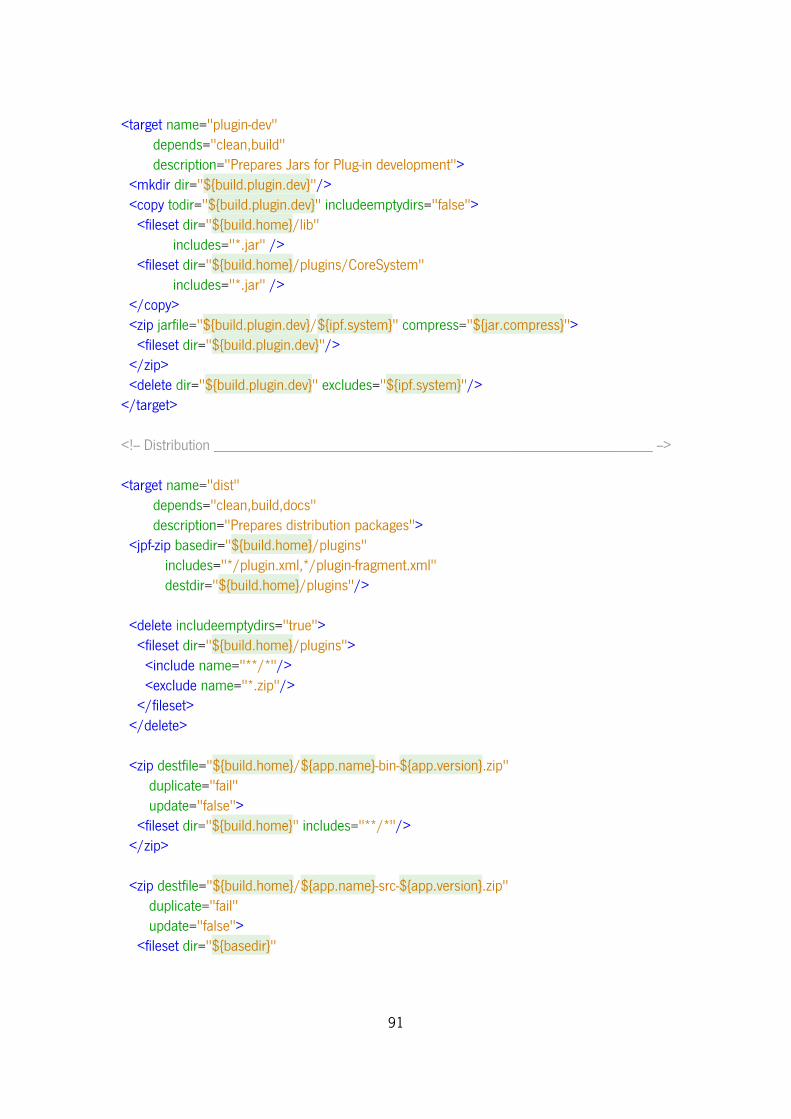
91
<target name="plugin-dev" depends="clean,build" description="Prepares Jars for Plug-in development"> <mkdir dir="${build.plugin.dev}"/> <copy todir="${build.plugin.dev}" includeemptydirs="false"> <fileset dir="${build.home}/lib" includes="*.jar" /> <fileset dir="${build.home}/plugins/CoreSystem" includes="*.jar" /> </copy> <zip jarfile="${build.plugin.dev}/${ipf.system}" compress="${jar.compress}"> <fileset dir="${build.plugin.dev}"/> </zip> <delete dir="${build.plugin.dev}" excludes="${ipf.system}"/> </target> <!-- Distribution _______________________________________________________ --> <target name="dist" depends="clean,build,docs" description="Prepares distribution packages"> <jpf-zip basedir="${build.home}/plugins" includes="*/plugin.xml,*/plugin-fragment.xml" destdir="${build.home}/plugins"/> <delete includeemptydirs="true"> <fileset dir="${build.home}/plugins"> <include name="**/*"/> <exclude name="*.zip"/> </fileset> </delete> <zip destfile="${build.home}/${app.name}-bin-${app.version}.zip" duplicate="fail" update="false"> <fileset dir="${build.home}" includes="**/*"/> </zip> <zip destfile="${build.home}/${app.name}-src-${app.version}.zip" duplicate="fail" update="false"> <fileset dir="${basedir}"
92
excludes="build,**/classes/**,.check*,.fb*,nbproject/private/**,build/**,logs/**,data/**,temp/**,*.zip,todo.txt,plugins/org.jpf.demo.toolbox.ftpmonitor/**"/> </zip> <delete includeemptydirs="true"> <fileset dir="${build.home}"> <include name="**/*" /> <exclude name="${app.name}-???-${app.version}.zip" /> </fileset> </delete> </target> <!-- Run Tests. _________________________________________________________ --> <target name="test" depends="build" description="Some tests"> <jpf-pack basedir="${build.home}/plugins" includes="*/plugin.xml,*/plugin-fragment.xml" destfile="${build.home}/all-plugins.jpa" /> <mkdir dir="${build.home}/all-plugins-extracted" /> <jpf-unpack srcfile="${build.home}/all-plugins.jpa" destdir="${build.home}/all-plugins-extracted" /> </target> </project>
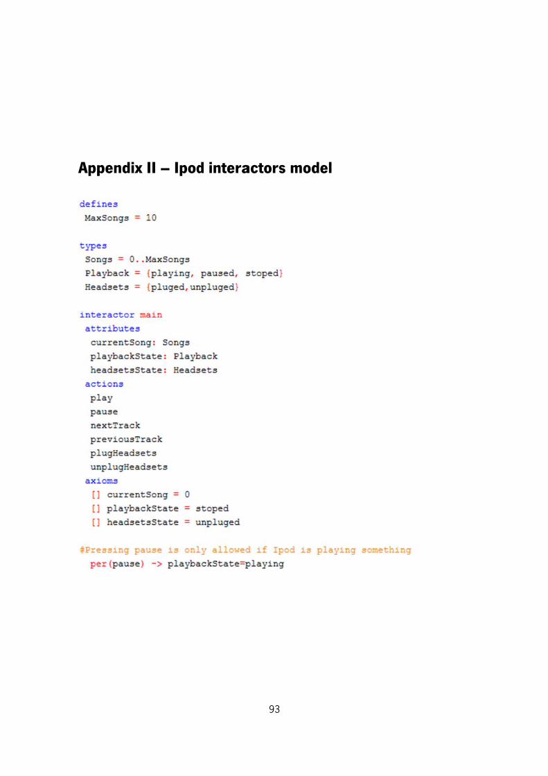
Apppendix III – Ipodd intera
93
actors mmodel
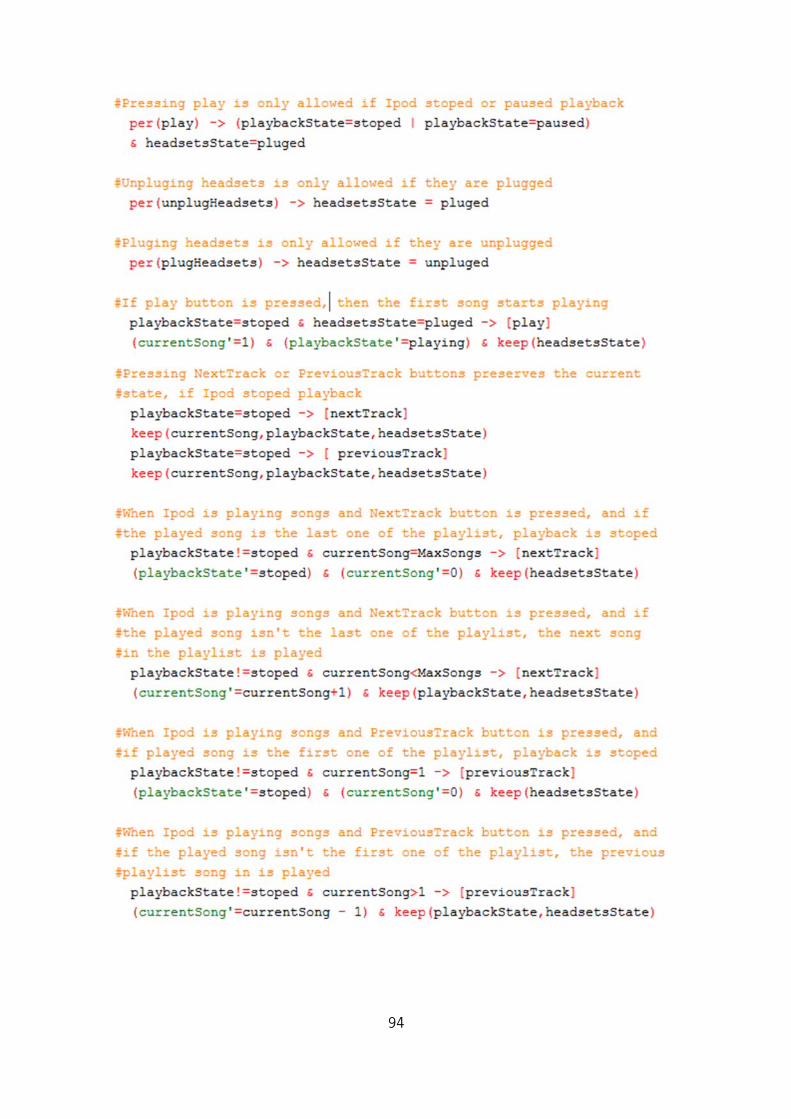
94
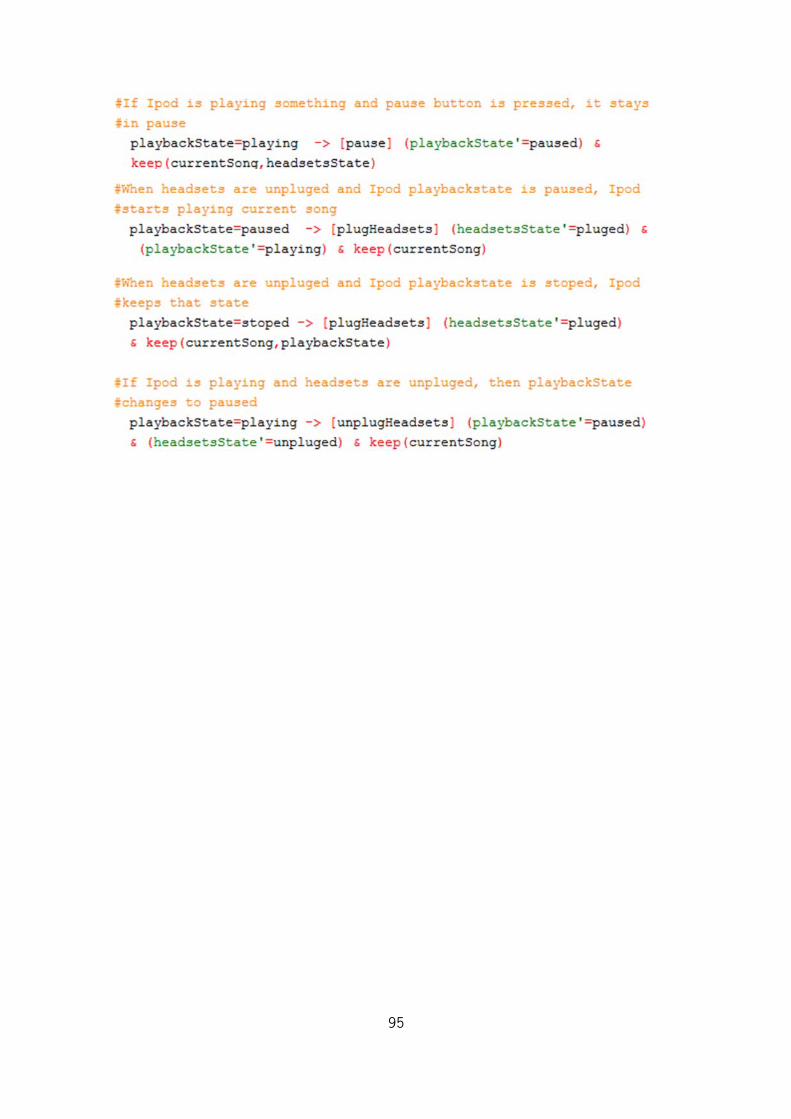
95
Recommended


