Embed Size (px)
Citation preview
Material prepared by: prof. Huixin Wu Page: 1 LAB REPORT SAMPLE
NEW YORK CITY COLLEGE OF TECHNOLOGY THE CITY UNIVERSITY OF NEW YORK
300 JAY STREET, BROOKLYN, NY 11201-1909
Department of Computer Engineering Technology
CET 3525L Electrical Networks Laboratory
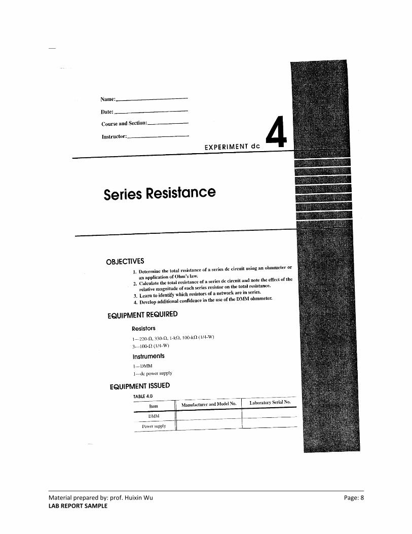
Series Resistance
Sophia Smith Partner: William Williams
Prof. Huixin Wu Fall 2010 (09/11/2010)
ABSTRACT
The physical construction of a series configuration circuit in a protoboard was build according to
the rules of series connectivity. The total resistance of a series circuit was measured first using
digital multimeter, DMM. The measured values were later compared with the calculated total
resistance, which was found by the principal of Ohm’s law and Kirchhoff’s voltage law. At the
end, the percent of difference was determined to be between 0.022% and 0.11% for two and
three resistors connected in series configuration.
Material prepared by: prof. Huixin Wu Page: 2 LAB REPORT SAMPLE
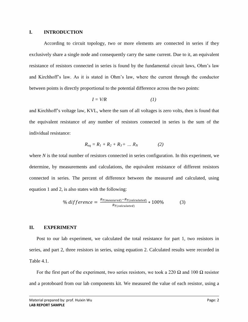
I. INTRODUCTION
According to circuit topology, two or more elements are connected in series if they
exclusively share a single node and consequently carry the same current. Due to it, an equivalent
resistance of resistors connected in series is found by the fundamental circuit laws, Ohm’s law
and Kirchhoff’s law. As it is stated in Ohm’s law, where the current through the conductor
between points is directly proportional to the potential difference across the two points:
I = V/R (1)
and Kirchhoff’s voltage law, KVL, where the sum of all voltages is zero volts, then is found that
the equivalent resistance of any number of resistors connected in series is the sum of the
individual resistance:
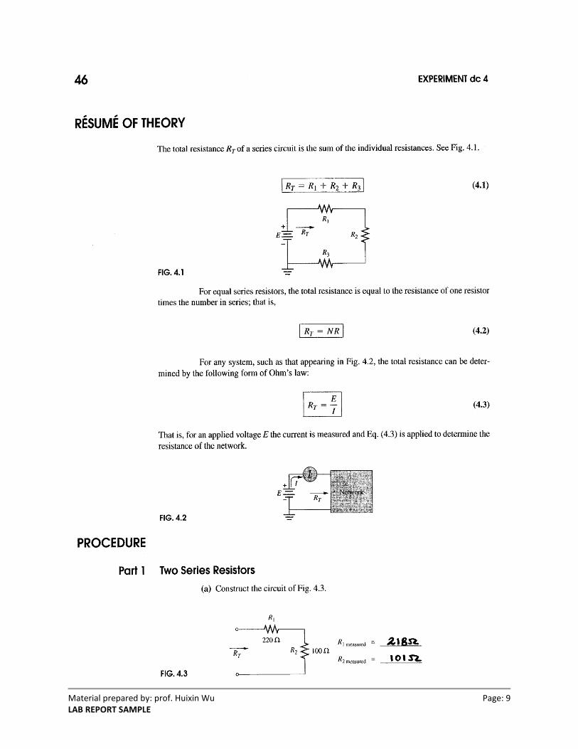
Req = R1 + R2 + R3 + … RN (2)
where N is the total number of resistors connected in series configuration. In this experiment, we
determine, by measurements and calculations, the equivalent resistance of different resistors
connected in series. The percent of difference between the measured and calculated, using
equation 1 and 2, is also states with the following:
(3)
II. EXPERIMENT
Post to our lab experiment, we calculated the total resistance for part 1, two resistors in
series, and part 2, three resistors in series, using equation 2. Calculated results were recorded in
Table 4.1.
For the first part of the experiment, two series resistors, we took a 220 Ω and 100 Ω resistor
and a protoboard from our lab components kit. We measured the value of each resistor, using a
Material prepared by: prof. Huixin Wu Page: 3 LAB REPORT SAMPLE
digital multimeter, and recorded our measurements in our lab manual. Later, we connected both
resistors in series configuration in our protoboard, and connected one terminal of the 220 Ω and
one terminal of the 100 Ω with the positive and negative lead of the digital multimeter,
respectively. We measured the total resistance and recorded our measurement in Table 4.1. After
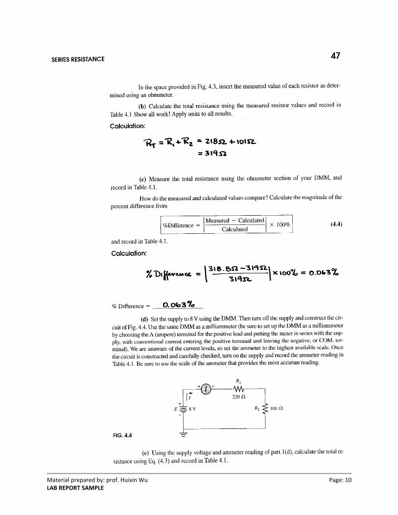
it, we obtained the leads for the power supply from the lab technician. We set the power supply
to 8 V, and connected the positive lead with one terminal of the 220 Ω resistor, and the negative
lead with the other terminal of the 100 Ω resistor. After it, we set our digital multimeter to
measure the current, so we swapped the positive lead of the multimeter to current input, and set it
to measure milli-amperes. We then connected the positive lead of the multimeter in series with
the circuit, the positive lead of the multimeter to the positive terminal of the power supply, and
the negative lead of the multimeter to one terminal of the 220 Ω resistor. We measured the
current as 25.1 mA. On a sheet of paper, we calculated the total resistance using Ohm’s law,
equation 1, and the percent of difference, using equation 3, between the measured total
resistance, 318.8 Ω, and the calculated total resistance using equation 1, 319 Ω, and equation 2,
318.7 Ω. All calculations were recorded in Table 4.1
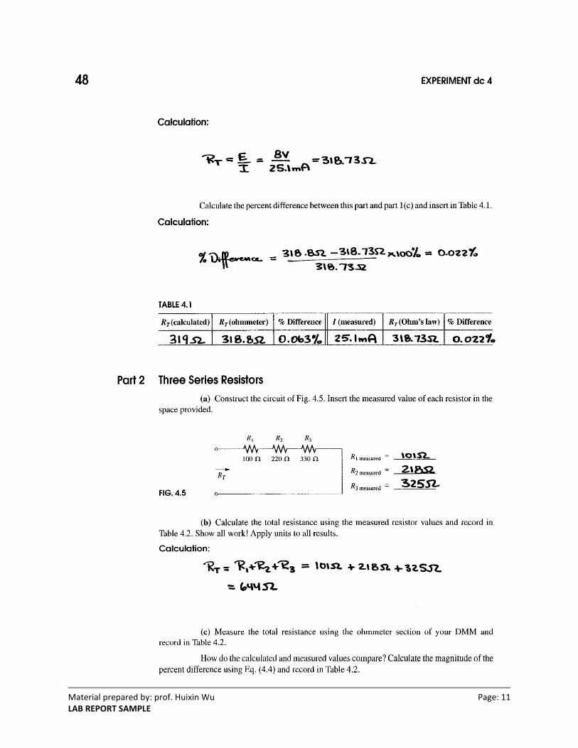
For the second part of our experiment, we obtained a 330 Ω from our components kit,
measured the resistance value as 325 Ω, and connected it in series with our previous series
circuit. We then measured the total resistance using a digital multimeter and recorded our
measurements in Table 4.2. After it, we connected the power supply, set to 8 volts, and the
ammeter in series with the three resistors connected in series. All measurements were recorded in
Table 4.2. On a sheet of paper, we calculated the total resistance using equation 2, and the
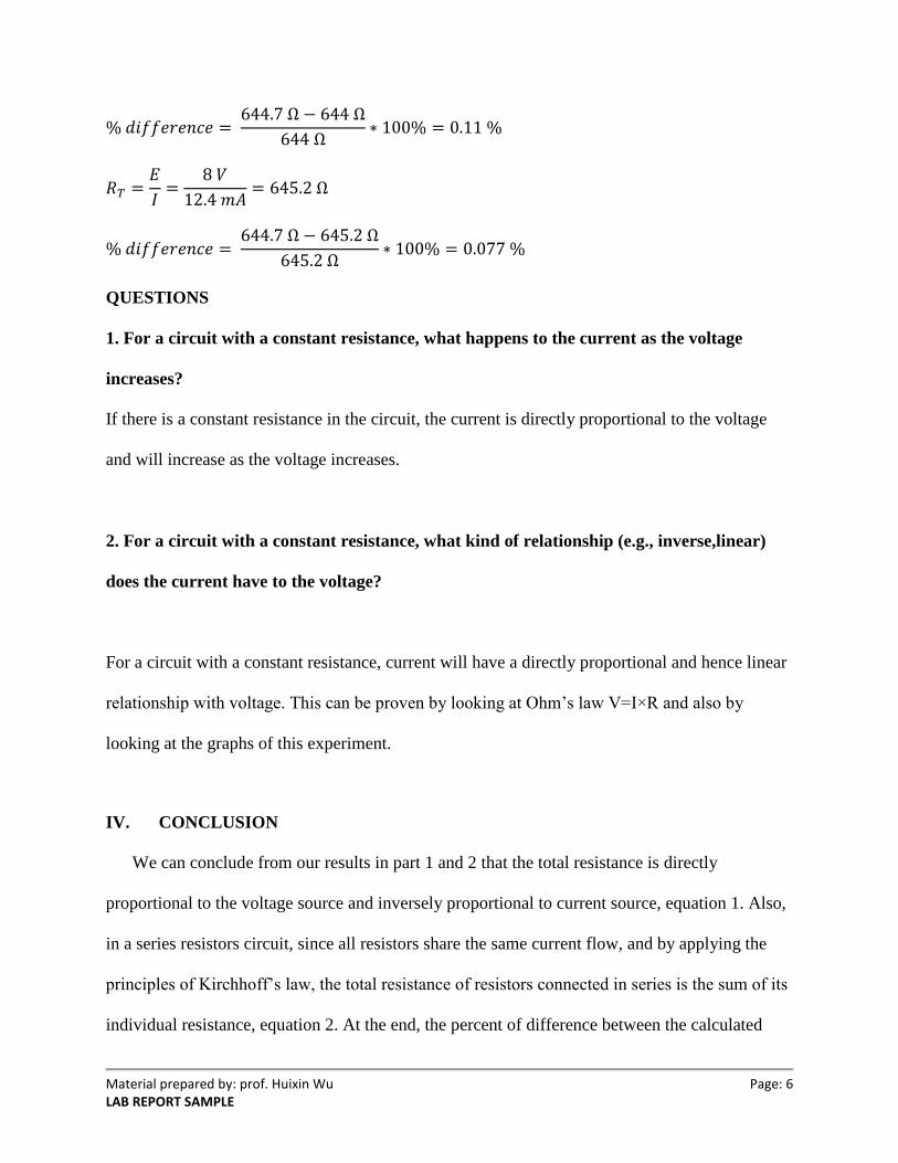
percent of difference between the measured total resistance, 644.7 Ω, and the calculated total
Material prepared by: prof. Huixin Wu Page: 4 LAB REPORT SAMPLE
resistance using equation 1, 644 Ω, and equation 2, 645.2 Ω. All calculations were recorded in
Table 4.2.
III. RESULTS AND DISCUSSION
For part 1, two series resistors configuration circuit, 100 Ω and 220 Ω resistors, was built to
find the total resistance. The total resistance was found by calculation, using equation 1 and 2,
and measurement, using a digital multimeter. Table 4.1 presents the total resistance of two
resistors connected in series and the percent of difference between the measured and calculated
value. Rearranging from equation 1, indicates that the total resistance of a series configuration
circuit is directly proportional to the voltage source and inversely proportional to the current
source. According to it, the calculated total resistance is found to be 318.7 Ω. Also, from
equation 2, the total resistance of a series configuration circuit is the sum of the individual
resistance connected in series, giving a calculated value of 319 Ω. In connection to it, the percent
of difference between each calculated value and measured value is found to be 0.022 %, for total
resistance calculated using equation 1, and 0.063%, for total resistance calculated using equation
2.
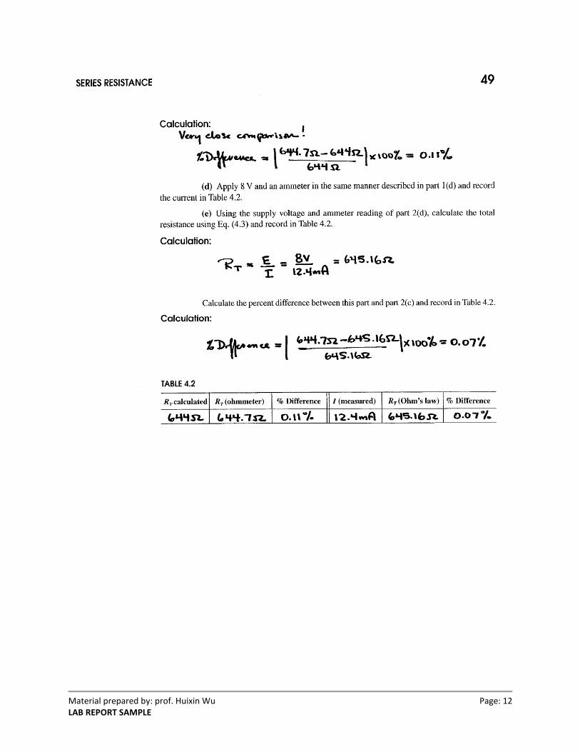
For part 2, Table 4.2 gives the total resistance of three series resistors connected in series
configuration, 100 Ω, 220 Ω, and 330 Ω resistors, and the percent of difference between the
measured and calculated value. The total resistance is found using equation 1, 645.2 Ω, equation
2, 644 Ω, and by measurement, 644.7 Ω, using a digital multimeter. At the end, the percent of
difference between each calculated value and measured value is found to be 0.07 %, for total
resistance calculated using equation 1, and 0.11%, for total resistance calculated using equation
2.
Material prepared by: prof. Huixin Wu Page: 5 LAB REPORT SAMPLE
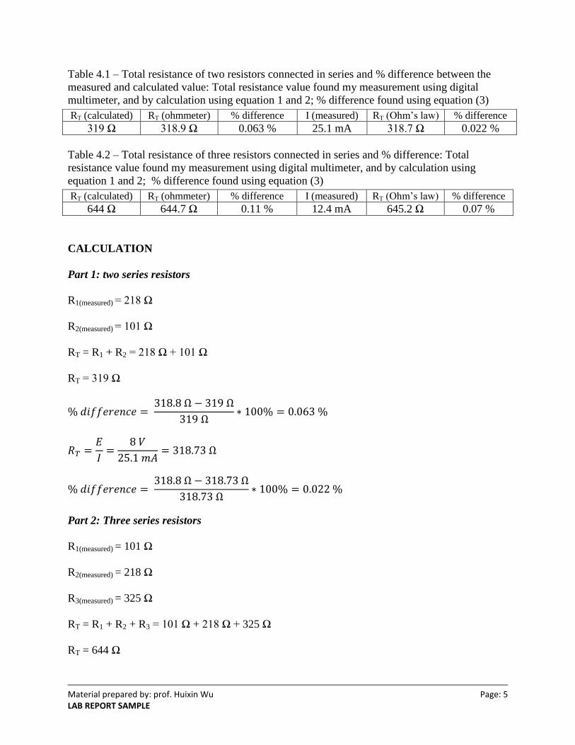
Table 4.1 – Total resistance of two resistors connected in series and % difference between the
measured and calculated value: Total resistance value found my measurement using digital
multimeter, and by calculation using equation 1 and 2; % difference found using equation (3)
Table 4.2 – Total resistance of three resistors connected in series and % difference: Total
resistance value found my measurement using digital multimeter, and by calculation using
equation 1 and 2; % difference found using equation (3)
CALCULATION
Part 1: two series resistors
R1(measured) = 218 Ω
R2(measured) = 101 Ω
RT = R1 + R2 = 218 Ω + 101 Ω
RT = 319 Ω
Part 2: Three series resistors
R1(measured) = 101 Ω
R2(measured) = 218 Ω
R3(measured) = 325 Ω
RT = R1 + R2 + R3 = 101 Ω + 218 Ω + 325 Ω
RT = 644 Ω
RT (calculated) RT (ohmmeter) % difference I (measured) RT (Ohm’s law) % difference
319 Ω 318.9 Ω 0.063 % 25.1 mA 318.7 Ω 0.022 %
RT (calculated) RT (ohmmeter) % difference I (measured) RT (Ohm’s law) % difference
644 Ω 644.7 Ω 0.11 % 12.4 mA 645.2 Ω 0.07 %
Material prepared by: prof. Huixin Wu Page: 6 LAB REPORT SAMPLE
QUESTIONS
1. For a circuit with a constant resistance, what happens to the current as the voltage
increases?
If there is a constant resistance in the circuit, the current is directly proportional to the voltage
and will increase as the voltage increases.
2. For a circuit with a constant resistance, what kind of relationship (e.g., inverse,linear)
does the current have to the voltage?
For a circuit with a constant resistance, current will have a directly proportional and hence linear
relationship with voltage. This can be proven by looking at Ohm’s law V=I×R and also by
looking at the graphs of this experiment.
IV. CONCLUSION
We can conclude from our results in part 1 and 2 that the total resistance is directly
proportional to the voltage source and inversely proportional to current source, equation 1. Also,
in a series resistors circuit, since all resistors share the same current flow, and by applying the
principles of Kirchhoff’s law, the total resistance of resistors connected in series is the sum of its
individual resistance, equation 2. At the end, the percent of difference between the calculated
Material prepared by: prof. Huixin Wu Page: 7 LAB REPORT SAMPLE
value and measured value is found to be between 0.022% and 0.11%. This indicates that the
founding of the total resistance by experiment is almost equal to the calculated value, using
different approach theories of resistance in series resistors configuration.
Material prepared by: prof. Huixin Wu Page: 8 LAB REPORT SAMPLE
Material prepared by: prof. Huixin Wu Page: 9 LAB REPORT SAMPLE
Material prepared by: prof. Huixin Wu Page: 10 LAB REPORT SAMPLE
Material prepared by: prof. Huixin Wu Page: 11 LAB REPORT SAMPLE
Material prepared by: prof. Huixin Wu Page: 12 LAB REPORT SAMPLE