Embed Size (px)
Citation preview
1
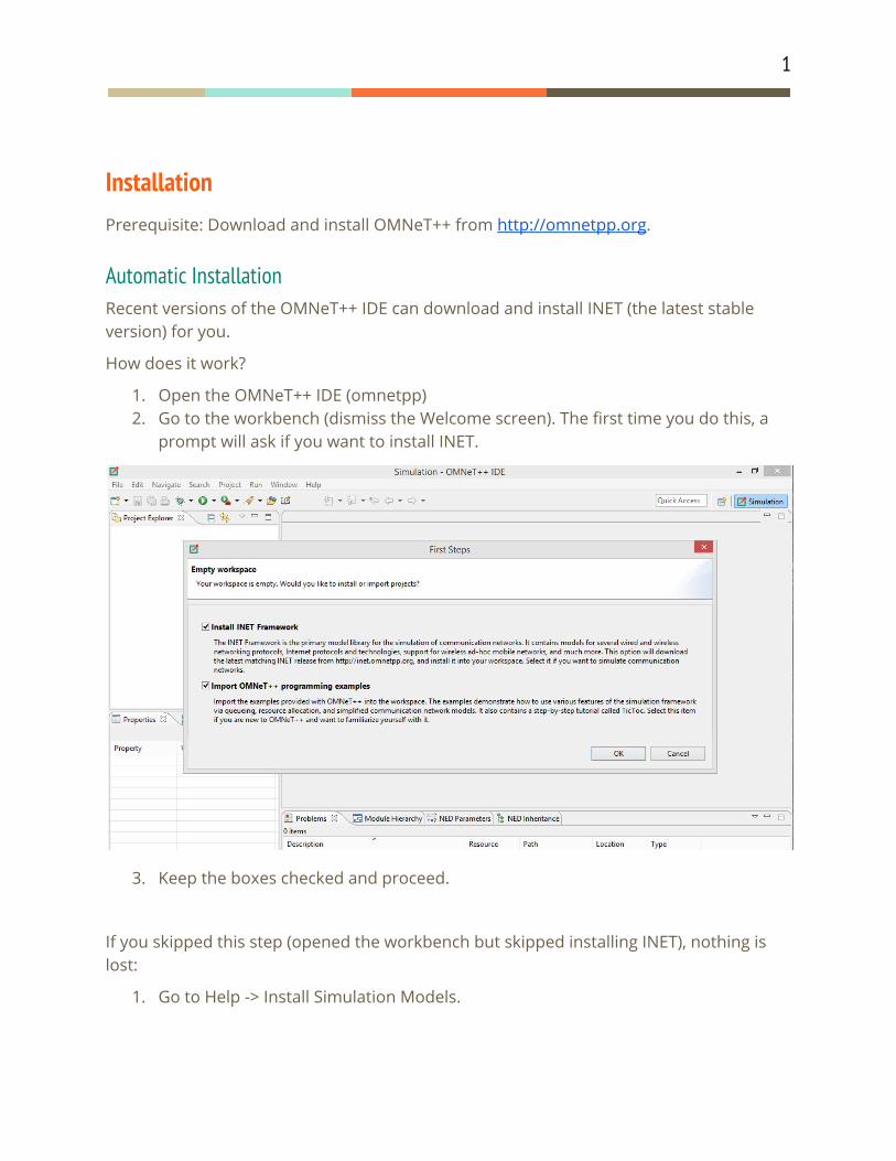
Installation Prerequisite: Download and install OMNeT++ from http://omnetpp.org.
Automatic Installation Recent versions of the OMNeT++ IDE can download and install INET (the latest stable version) for you.
How does it work?
1. Open the OMNeT++ IDE (omnetpp) 2. Go to the workbench (dismiss the Welcome screen). The first time you do this, a
prompt will ask if you want to install INET.
3. Keep the boxes checked and proceed.
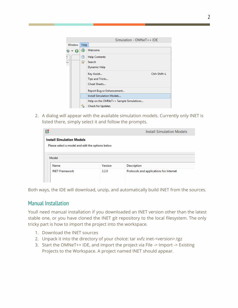
If you skipped this step (opened the workbench but skipped installing INET), nothing is lost:
1. Go to Help -> Install Simulation Models.
2
2. A dialog will appear with the available simulation models. Currently only INET is listed there, simply select it and follow the prompts.
Both ways, the IDE will download, unzip, and automatically build INET from the sources.
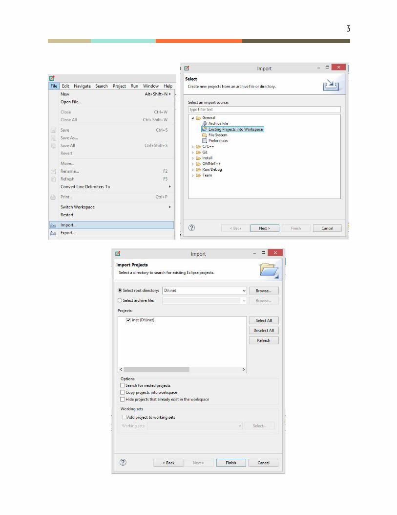
Manual Installation Youll need manual installation if you downloaded an INET version other than the latest stable one, or you have cloned the INET git repository to the local filesystem. The only tricky part is how to import the project into the workspace.
1. Download the INET sources 2. Unpack it into the directory of your choice: tar xvfz inet-<version>.tgz 3. Start the OMNeT++ IDE, and import the project via File -> Import -> Existing
Projects to the Workspace. A project named INET should appear.
3
4
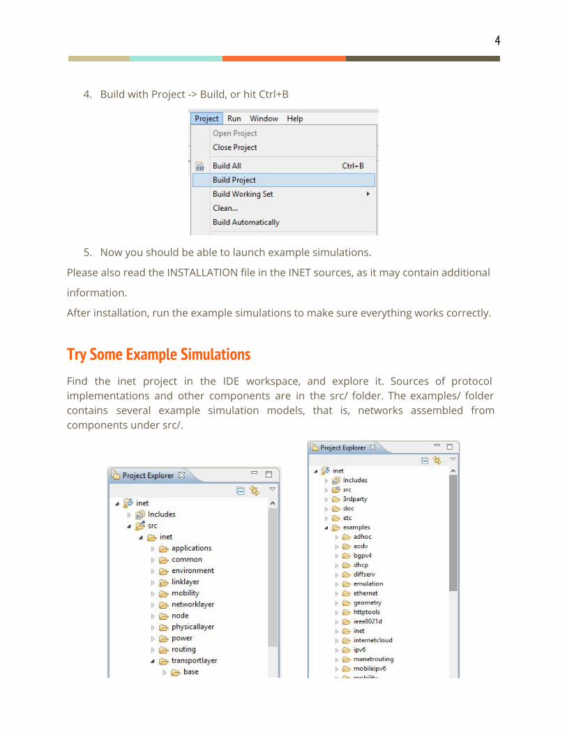
4. Build with Project -> Build, or hit Ctrl+B
5. Now you should be able to launch example simulations.
Please also read the INSTALLATION file in the INET sources, as it may contain additional
information.
After installation, run the example simulations to make sure everything works correctly.
Try Some Example Simulations Find the inet project in the IDE workspace, and explore it. Sources of protocol implementations and other components are in the src/ folder. The examples/ folder contains several example simulation models, that is, networks assembled from components under src/.
5
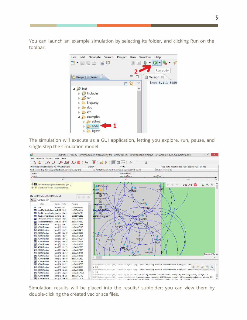
You can launch an example simulation by selecting its folder, and clicking Run on the toolbar.
The simulation will execute as a GUI application, letting you explore, run, pause, and single-step the simulation model.
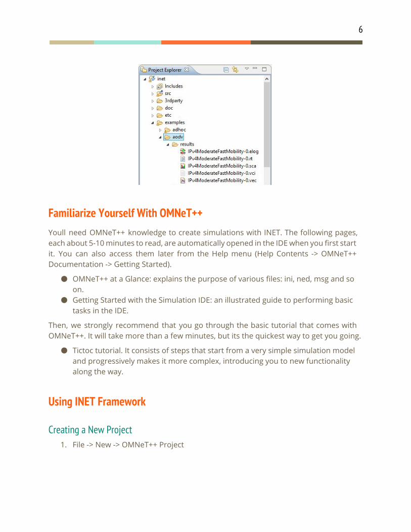
Simulation results will be placed into the results/ subfolder; you can view them by double-clicking the created vec or sca files.
6
Familiarize Yourself With OMNeT++ Youll need OMNeT++ knowledge to create simulations with INET. The following pages, each about 5-10 minutes to read, are automatically opened in the IDE when you first start it. You can also access them later from the Help menu (Help Contents -> OMNeT++ Documentation -> Getting Started).
OMNeT++ at a Glance: explains the purpose of various files: ini, ned, msg and so on.
Getting Started with the Simulation IDE: an illustrated guide to performing basic tasks in the IDE.
Then, we strongly recommend that you go through the basic tutorial that comes with OMNeT++. It will take more than a few minutes, but its the quickest way to get you going.
Tictoc tutorial. It consists of steps that start from a very simple simulation model and progressively makes it more complex, introducing you to new functionality along the way.
Using INET Framework
Creating a New Project 1. File -> New -> OMNeT++ Project
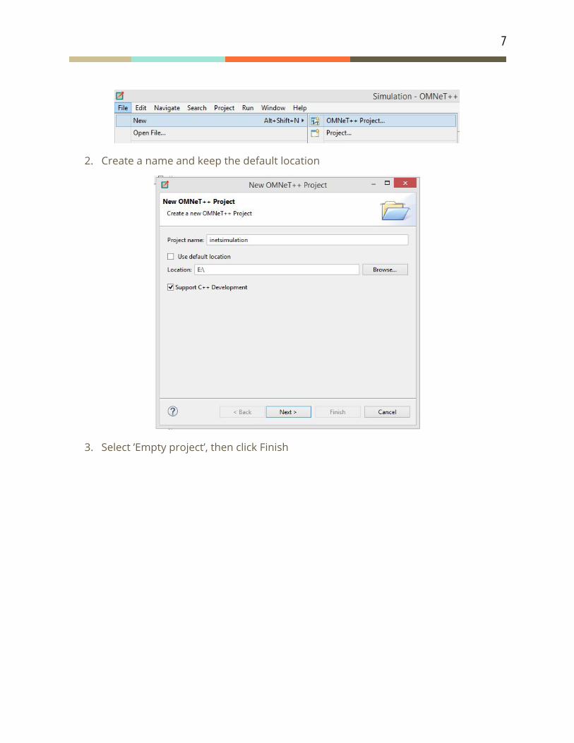
7
2. Create a name and keep the default location
3. Select ’Empty project’, then click Finish
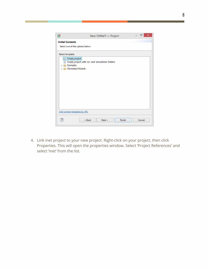
8
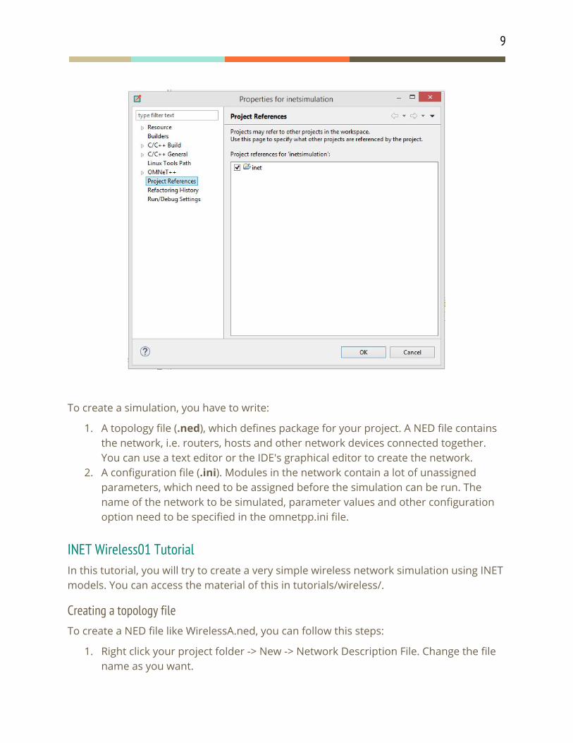
4. Link inet project to your new project. Right-click on your project, then click Properties. This will open the properties window. Select ’Project References’ and select ’inet’ from the list.
9
To create a simulation, you have to write:
1. A topology file (.ned), which defines package for your project. A NED file contains the network, i.e. routers, hosts and other network devices connected together. You can use a text editor or the IDE's graphical editor to create the network.
2. A configuration file (.ini). Modules in the network contain a lot of unassigned parameters, which need to be assigned before the simulation can be run. The name of the network to be simulated, parameter values and other configuration option need to be specified in the omnetpp.ini file.
INET Wireless01 Tutorial In this tutorial, you will try to create a very simple wireless network simulation using INET models. You can access the material of this in tutorials/wireless/.
Creating a topology file To create a NED file like WirelessA.ned, you can follow this steps:
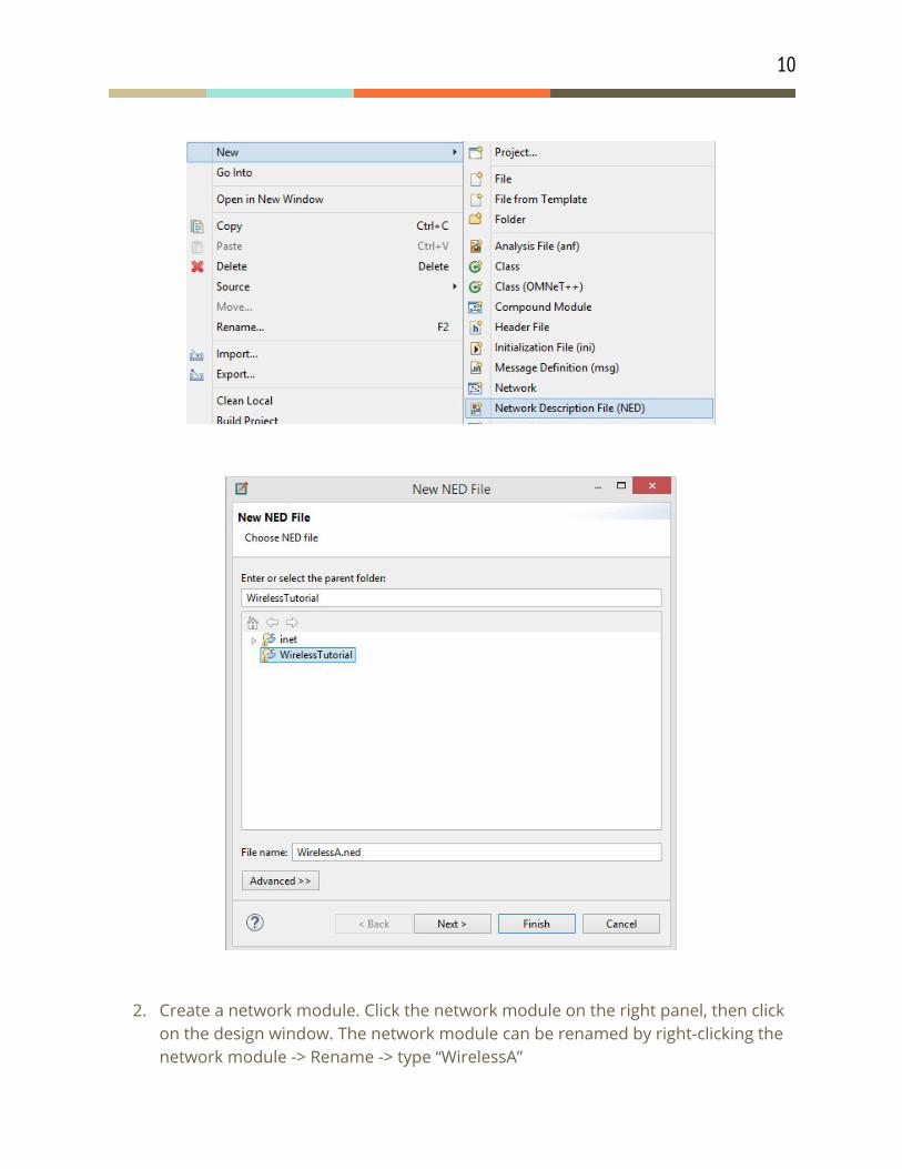
1. Right click your project folder -> New -> Network Description File. Change the file name as you want.
10
2. Create a network module. Click the network module on the right panel, then click on the design window. The network module can be renamed by right-clicking the network module -> Rename -> type “WirelessA”
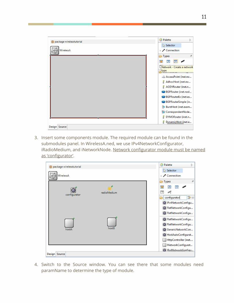
11
3. Insert some components module. The required module can be found in the submodules panel. In WirelessA.ned, we use IPv4NetworkConfigurator, iRadioMedium, and iNetworkNode. Network configurator module must be named as ‘configurator’.
4. Switch to the Source window. You can see there that some modules need paramName to determine the type of module.
12
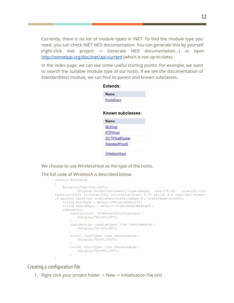
Currently, there is no list of module types in INET. To find the module type you need, you can check INET NED documentation. You can generate this by yourself (right-click inet project -> Generate NED documentation…) or open http://omnetpp.org/doc/inet/api-current (which is not up-to-date).
In the index page, we can see some useful starting points. For example, we want to search the suitable module type of our hosts. If we see the documentation of StandardHost module, we can find its parent and known subclasses.
We choose to use WirelessHost as the type of the hosts.
The full code of WirelessA is described below. network WirelessA @display("bgb=500,500");
@figure[thruputInstrument](type=gauge; pos=370,90; size=120,120; maxValue=2500; tickSize=500; colorStrip=green 0.75 yellow 0.9 red;label=Number of packets received; moduleName=hostB.udpApp[0]; signalName=rcvdPk); string hostType = default("WirelessHost"); string mediumType = default("IdealRadioMedium"); submodules: configurator: IPv4NetworkConfigurator @display("p=149,29"); radioMedium: <mediumType> like IRadioMedium @display("p=309,24"); hostA: <hostType> like INetworkNode @display("p=50,250"); hostB: <hostType> like INetworkNode @display("p=450,250");
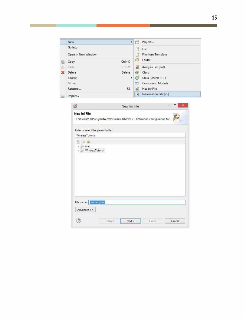
Creating a configuration file 1. Right click your project folder -> New -> Initialization File (ini)
13
14
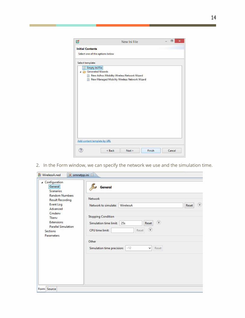
2. In the Form window, we can specify the network we use and the simulation time.
15
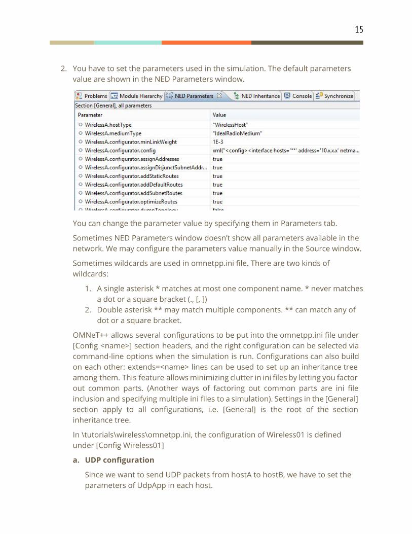
2. You have to set the parameters used in the simulation. The default parameters value are shown in the NED Parameters window.
You can change the parameter value by specifying them in Parameters tab.
Sometimes NED Parameters window doesn’t show all parameters available in the network. We may configure the parameters value manually in the Source window.
Sometimes wildcards are used in omnetpp.ini file. There are two kinds of wildcards:
1. A single asterisk * matches at most one component name. * never matches a dot or a square bracket (., [, ])
2. Double asterisk ** may match multiple components. ** can match any of dot or a square bracket.
OMNeT++ allows several configurations to be put into the omnetpp.ini file under [Config <name>] section headers, and the right configuration can be selected via command-line options when the simulation is run. Configurations can also build on each other: extends=<name> lines can be used to set up an inheritance tree among them. This feature allows minimizing clutter in ini files by letting you factor out common parts. (Another ways of factoring out common parts are ini file inclusion and specifying multiple ini files to a simulation). Settings in the [General] section apply to all configurations, i.e. [General] is the root of the section inheritance tree.
In \tutorials\wireless\omnetpp.ini, the configuration of Wireless01 is defined under [Config Wireless01]
a. UDP configuration
Since we want to send UDP packets from hostA to hostB, we have to set the parameters of UdpApp in each host.
16
Configure an application for hostA that sends a constant UDP traffic around 800Kbps (+ protocol overhead)
*.hostA.numUdpApps = 1 *.hostA.udpApp[0].typename = "UDPBasicApp" *.hostA.udpApp[0].destAddresses = "hostB" *.hostA.udpApp[0].destPort = 5000 *.hostA.udpApp[0].messageLength = 1000B *.hostA.udpApp[0].sendInterval = exponential(10ms)
Configure an app for hostB that receives the UDP traffic (and simply drops the data)
*.hostB.numUdpApps = 1 *.hostB.udpApp[0].typename = "UDPSink" *.hostB.udpApp[0].localPort = 5000
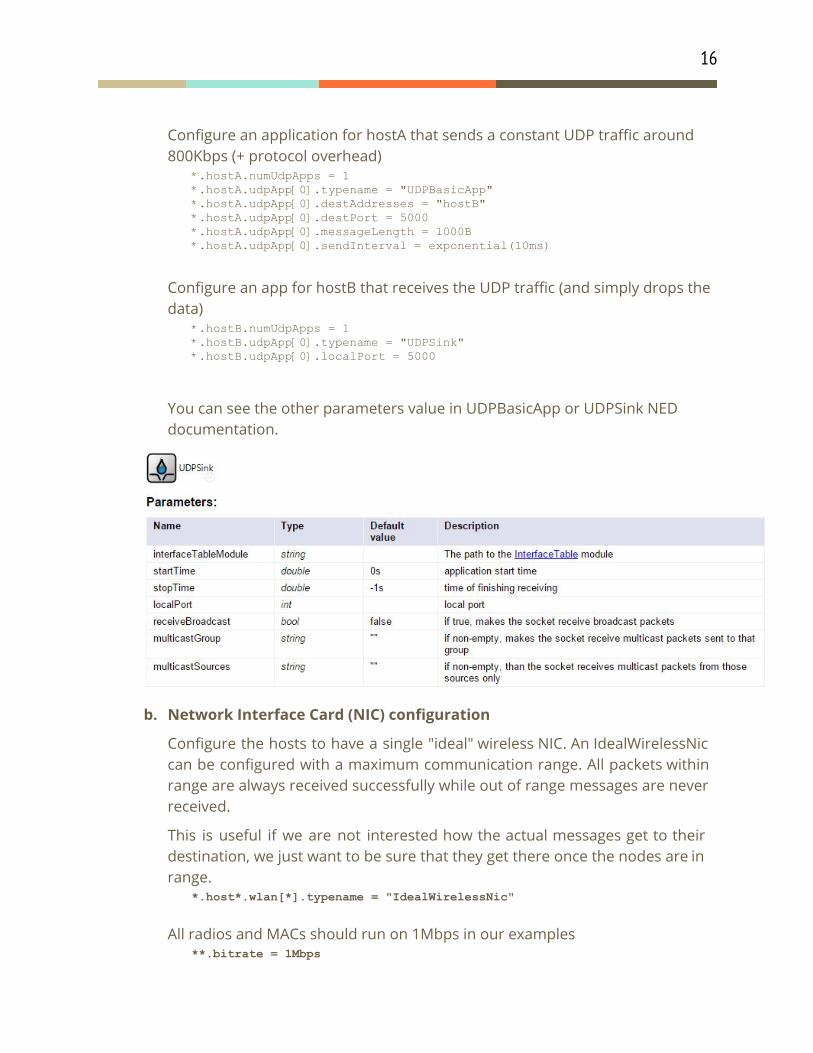
You can see the other parameters value in UDPBasicApp or UDPSink NED documentation.
b. Network Interface Card (NIC) configuration
Configure the hosts to have a single "ideal" wireless NIC. An IdealWirelessNic can be configured with a maximum communication range. All packets within range are always received successfully while out of range messages are never received.
This is useful if we are not interested how the actual messages get to their destination, we just want to be sure that they get there once the nodes are in range.
*.host*.wlan[*].typename = "IdealWirelessNic"
All radios and MACs should run on 1Mbps in our examples **.bitrate = 1Mbps
17
Mandatory physical layer parameters *.host*.wlan[*].radio.transmitter.maxCommunicationRange = 500m
Simplify the IdealWirelessNic even further. We do not care even if there are transmission collisions. Any number of nodes in range can transmit at the same time and the packets will be still successfully delivered.
*.host*.wlan[*].radio.receiver.ignoreInterference = true
The other configuration tutorial can be seen in tutorial/wireless/
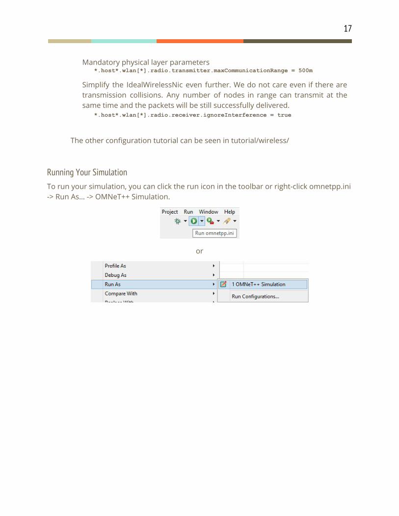
Running Your Simulation To run your simulation, you can click the run icon in the toolbar or right-click omnetpp.ini -> Run As… -> OMNeT++ Simulation.
or
18
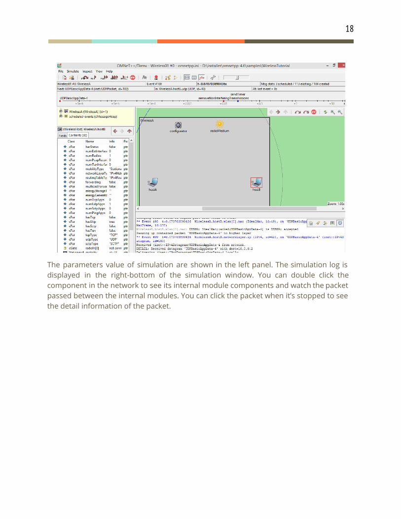
The parameters value of simulation are shown in the left panel. The simulation log is displayed in the right-bottom of the simulation window. You can double click the component in the network to see its internal module components and watch the packet passed between the internal modules. You can click the packet when it’s stopped to see the detail information of the packet.
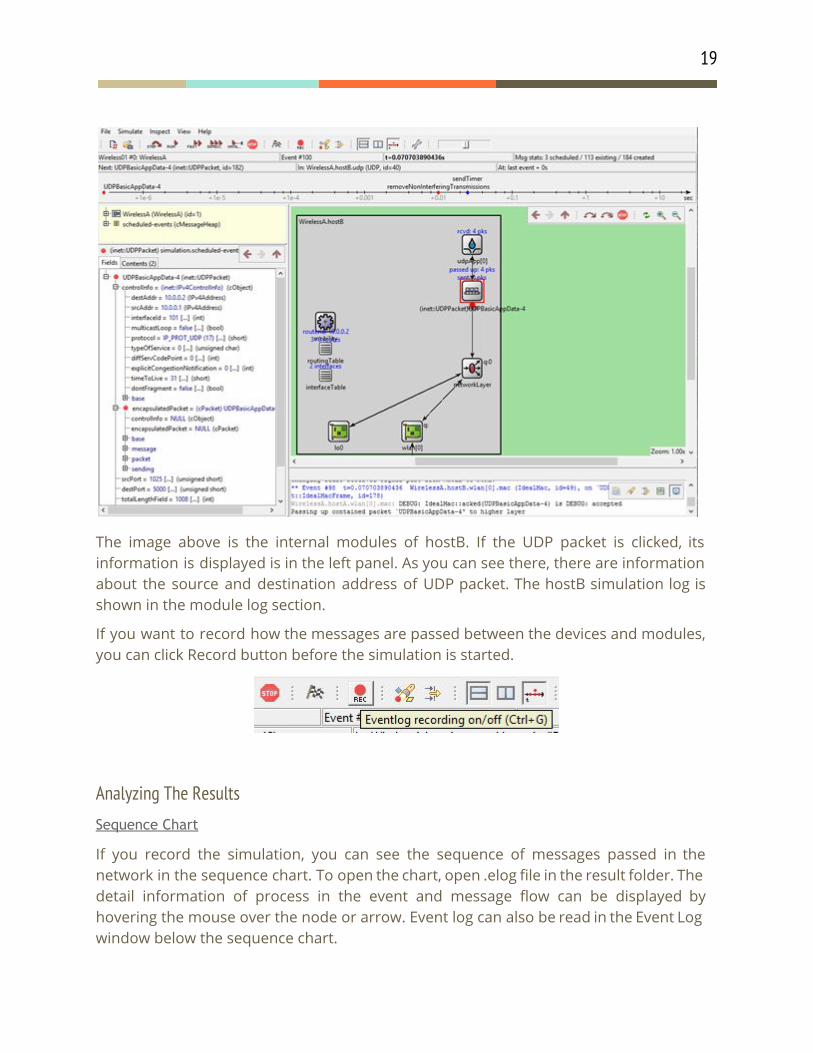
19
The image above is the internal modules of hostB. If the UDP packet is clicked, its information is displayed is in the left panel. As you can see there, there are information about the source and destination address of UDP packet. The hostB simulation log is shown in the module log section.
If you want to record how the messages are passed between the devices and modules, you can click Record button before the simulation is started.
Analyzing The Results
Sequence Chart
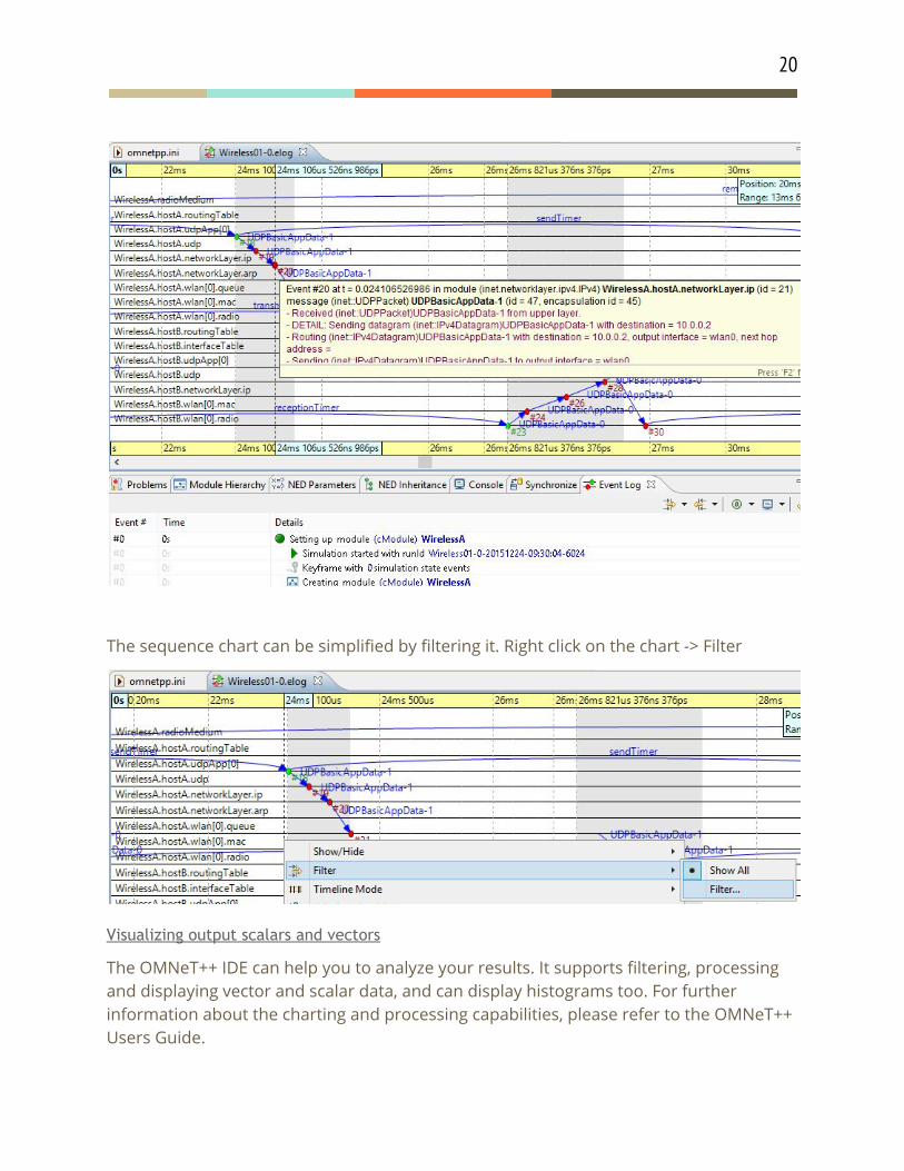
If you record the simulation, you can see the sequence of messages passed in the network in the sequence chart. To open the chart, open .elog file in the result folder. The detail information of process in the event and message flow can be displayed by hovering the mouse over the node or arrow. Event log can also be read in the Event Log window below the sequence chart.
20
The sequence chart can be simplified by filtering it. Right click on the chart -> Filter
Visualizing output scalars and vectors
The OMNeT++ IDE can help you to analyze your results. It supports filtering, processing and displaying vector and scalar data, and can display histograms too. For further information about the charting and processing capabilities, please refer to the OMNeT++ Users Guide.