Embed Size (px)
DESCRIPTION
Citation preview

This Article was presented by the Author in the Seminar`CMOAT` organized by the ISM-Dhanbad on 15th-16th September 2006
Author: Tikeshwqr Mahto, Dy. Director of Mines Safety, Bilaspur Region [email protected]
MODIFICATION OF RMR OR GEOMECHANICAL CLASSIFICATION SYSTEM DESIGNED BY CMRI TO APPLY IN INDIAN COAL MINES.
Introduction
Strata control in underground coal mines has always remained a challenging task to practicing mining Engineers and research Institutions. It’s all due to mysteries hidden inside the earth, which is impossible to understand. That is why all the strata control mechanisms developed are based on the empirical approach. And any empirical system developed, based on practical experience and studying geotechnical condition of few mines can not be a universal system.. In this paper the author is suggesting some modification in the Geomechanical classification system (or RMR system) developed by CMRI-ISM based on Bieniawski`s Geomechanical classification system (or RMR system).
Geomechanical classification system (RMR System) designed by `CMRI-ISM ` :-
In the Bieniawski`s Geomechanics classification or Rock Mass Rating (RMR) system, CMRI has made some changes for applying in Indian conditions. This modified system is known as CMRI `S RMR system. In this system, five parameters were identified for designing support system in underground roadways, which are listed below- Parameters Max. Rating(a) Layer thickness 30 (b) Structural features 25 (c) Weatherability 20(d) Rock strength 15(e) Ground water 10 --------------------- Total = 100 Based on the geotechnical studies of above five parameters, RMR of immediate roof is calculated by the weighted average method.
R = R1*t1 + R2*t2 + R3*t3 + R4*t4+ ----------+ Rn*tn -------------------------------------------------------------- t1 + t2 + t3 +t4 + -----------------+ tn Where R1, R2,R3,R4,-------- Rn are RMR`S of different layers having thickness t1, t2, t3, t4,--------tn respectively of immediate roof upto 2m heights and R is weighted average RMR of the immediate roof.
Empirical formulae given by CMRI for calculating ‘Rock Load’ are as follows:-
(A) Rock load in the gallery:- RL (t/sq.m) = W*d (1.7 -0.037R +0.0002R2) Where, RL = rock load in the development gallery, W = width of the gallery, d = density of the immediate roof rock, and R = RMR of the immediate roof.
B) Rock load at junction of the galleries:- RL (t/sq.m) = 5(W)1/3*d*[1- RMR/100]2
1

Critical studies on rock load calculation formula designed by CMRI for Bord &Pillar development working based on mathematical approach : -
Since, Rock load (R/L) = W*d* (1.7-0.037R +0.0002R2) t/sq.m
Conditions assumed-
Maximum value of RMR(R) = 100 Minimum value of RMR(R) = 0 Rock load will be maximum when RMR is minimum (0) Rock load will be minimum when RMR is maximum(100 Hence, maximum rock load (R/L) =Wd [1.7-0.037(0) +0.0002(0)] =1.7Wd Minimum rock load (R/L) = Wd [1.7-0.037(100) +0.0002(100)2] = Wd [1.7-3.7 +2] =Wd[0] = 0Where `W` is width of gallery and `d` is density of immediate roof.
Again from rock load equation, R/L =Wd [1.7-0.037R+0.0002R2] = Wd f(R) Where, f(R) =1.7-0.037R+0.0002R2, a function of R (RMR) which is a parabolic equation.
But this equation i.e. f(R) does not fulfill the assumed conditions listed above. Minimum value of rock load(R/L) or f(R) does not occur at R=100, it occurs at R=92.5 and also f(R) has zero value at R=85 and R=100 which indicates the failure of assumed conditions.
Justification for the above statements are given below by mathematical calculations and also by plotting f(R) vs. R in fig.1
support system designed by CMRI. f(R)=1.7-0.037R+0.0002R2
-50
0
50
100
150
200
250
300
-20 0 20 40 60 80 100 120 140
R(RMR)
f(R)*1
00
f®*100
Fig.1
Since, f(R) =1.7-0.037R+0.0002R2
=a - bR + cR2, Where, a=1.7, b=0.037 & c=0.0002
2

For maximum or minimum value of f(R), its first derivative should be zero at R=100, because the parabolic curve touches the X-axis at R=100.
i.e. df(R)/dR =0Or, d( a-bR +cR2 )/dR=0Or, -b + 2cR = 0
But, by putting values of b, c & R, from the above formula
- b + 2cR= - 0.037 +2*0.0002*100 = -0.037 +0.04 = 0.003
i.e. df(R)/dR, or slope of the curve is not equal to zero at R= 100, which means failure of Conditions assumed.
Again, if -b +2cR= 0
Then, R= b/2c, or R= 0.037/ 2*0.0002
or, R= 92.5i.e. Slope of the curve is zero at R=92.5 , which is also failure of assumed conditions. It should be at R= 100.
Again, minimum value of f(R) occurs at R=92.5.So minimum value of f(R) [at R=92.5] = a –bR + cR2
= 1.7-0.037*92.5 +0.0002*(92.5)2
= - 0.011 [negative value]This is impossible, because f(R) or rock load shall never have negative value. This is also a drawback of the CMRI`S Geomechanical classification system.
Again, in this system, value of f(R) will be zero at two values of R, which is also a drawback of this system. It will be found out mathematically in this way;
Since, f(R) =0Or, a- bR +cR2 =0
Or, R= [b ± (b2- 4ac)1/2]/2c , where a= 1.7, b =0.037 & c= 0.0002
Hence, R has two values at which f(R)=0
i.e. R1 = [b+ (b2-4ac) 1/2]/2c = [0.037+ {(0.037)2 - 4*1.7*0.0002}1/2]/2*0.0002 = 100, and
R2 = [b- (b2-4ac) 1/2]/2c
= [0.037- {(0.037)2 – 4*1.7*0.0002}1/2]/2*0.0002
= 85
The parabolic curve f(R) cuts the X- axis at R =85 and extends in negative zone which again reflects back and cuts the X-axis at R= 100. All these details have been shown in fig.1 .In Fig.1 point of reflection is at R= 92.5, but as per assumption it should be at R= 100 and also the value of f(R) or rock load is negative between R=85 & R=100, which is not possible. All these drawbacks have been rectified in modified system suggested by the author in detail, which is mentioned below.
MODIFICATIN SUGGESTED BY AUTHOR
Modification of values of constants a, b & c for clear representation of previous assumed conditions.
3

Since , f(R) = a – bR +cR2
Conditions to be fulfilled :-
f(R) = 0 , at R=100, -------- (1) df(R)/dR = 0 at R= 100 ---------(2)
since, f(R) = 0 at R= 100 or a – bR + cR2 = 0 or R = [b± (b2- 4ac) 1/2]/2c
-------(3) Again, since df(R)/dR = 0
or -b + 2cR =0 or R= b/ 2c ---------- (4) Comparing equation (3) & (4) , it can be inferred that b2- 4ac = 0
i.e. b2 =4ac ---------- (5)
finally we have two equations (4) & (5) and variables are three , therefore one variable shall be assumed to find out the values of other two variables.
If a= 1.7 has any scientific or practical significance, then it can be assumed as value of one variable. Solving equations (4) & (5) we get,
c = a/R2
or, c =1.7/ (100)2 [where R=100 & a =1.7] = 0.00017 ----------------- (6)
Again putting the values of `a` & `c` in equation (5) , we get b = (4ac) 1/2
= (4*1.7*0.00017)1/2
= 0.034 --------------- (7)Hence, modified values of constants are: -
a = 1.7, b = 0.034 & c = 0.00017 and modified equations of f(R) & rock load are as follows:f(R) = 1.7 – 0.034R + 0.00017R2, ----------------- (8)
Rock load(R/L) = W*d* f(R) = W*d (1.7 – 0.034R +0.00017R2) ---------- (9)
The above equation will fulfill all the pre-assumed conditions i.e. f(R) =0, at R= 100, and df(R)/dR = 0, at R=100 and also there will be no negative value of f(R) & rock load
between the range R= 0 to 100. These are clearly shown in fig.2
4

FIG.2
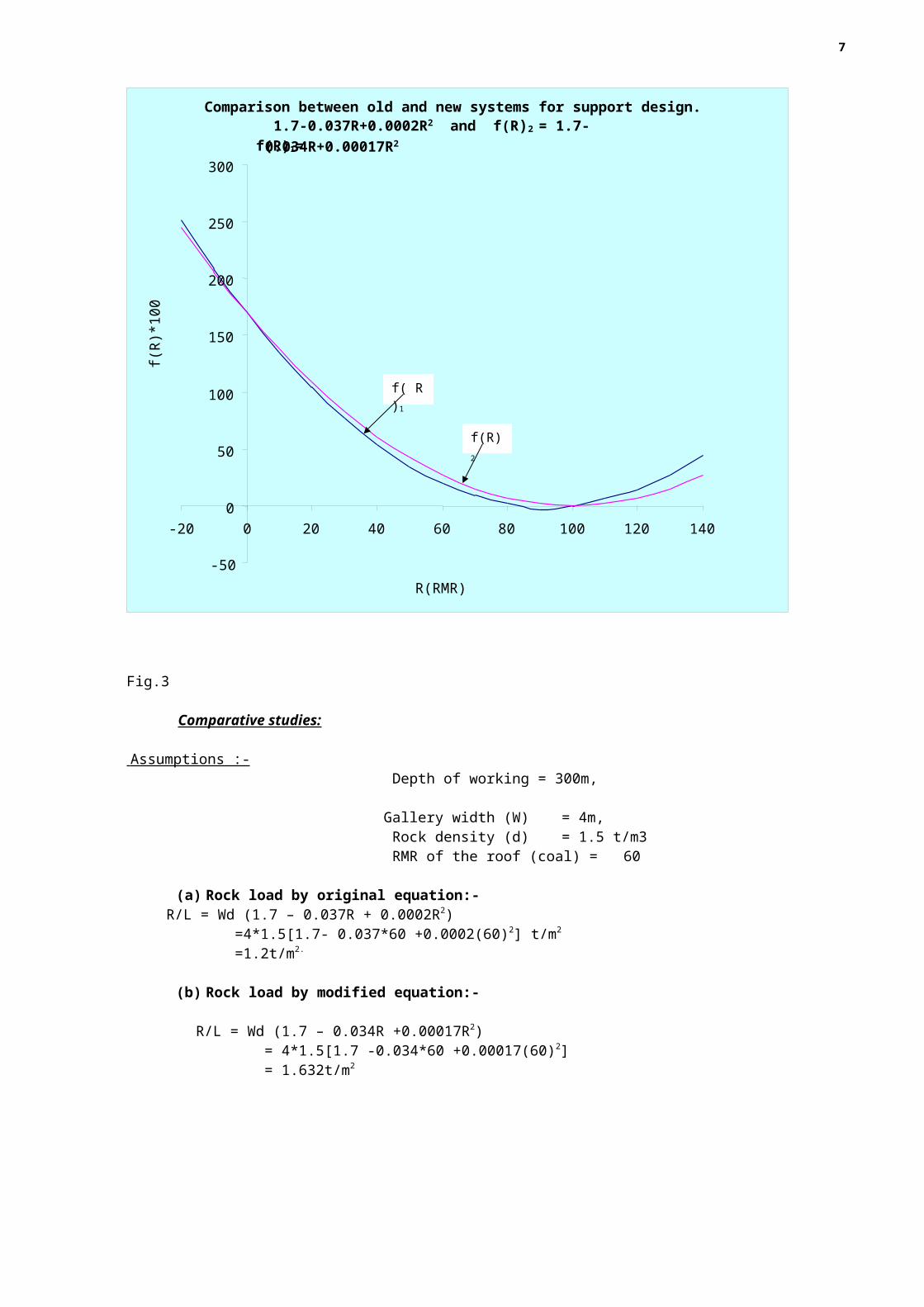
Comparison between the original and modified systems of Geomechanical classification Comparing both the equations i.e. original equation and modified equation , we can clearly distinguish between the original and modified system for support design in development and depillaring working. It is shown below in Fig.3. Rock load calculated by the modified system as per RMR of the roof rock of underground roadways is more in comparison to the original system, which will subsequently improve the support resistance required for strata control.
Original equation, f(R)1 =1.7 -0.037R +0.0002R2, and Modified equation(R)2= 1.7-0.034R+0.00017R2
5

Fig.3 Comparative studies:
Assumptions :- Depth of working = 300m,
Gallery width (W) = 4m, Rock density (d) = 1.5 t/m3 RMR of the roof (coal) = 60
(a) Rock load by original equation:-R/L = Wd (1.7 – 0.037R + 0.0002R2) =4*1.5[1.7- 0.037*60 +0.0002(60)2] t/m2
=1.2t/m2.
(b) Rock load by modified equation:-
R/L = Wd (1.7 – 0.034R +0.00017R2) = 4*1.5[1.7 -0.034*60 +0.00017(60)2] = 1.632t/m2
Support Pattern;-
Comparison between old and new systems for support design. f(R)1= 1.7-0.037R+0.0002R2 and f(R)2 = 1.7-0.034R+0.00017R2
-50
0
50
100
150
200
250
300
-20 0 20 40 60 80 100 120 140
R(RMR)
f(R
)*10
0
f(R)2
f( R)1
6
Let the method of support system is roof bolting, and bearing capacity of one roof bolt is about 8t.
(1) Support pattern of original system:-
Rock load = 1.2t/m2
F.O.S. = 1.8 Hence, support resistance offered by a roof bolt = bearing capacity of roof bolt ---------------------------------- Area supported by a roof bolt
= 8/A t/m2
Again, support resistance = rock load * F.O.S. = 1.2 *1.8 =2.16t/m2
. Thus comparing the above two equations we get,
8/A = 2.16, Or, A= 8/2.16 = 3.70 m2, or 1.90m * 1.90m in square pattern
i.e. area supported by one roof bolt is 3.70m2 .
(2) Support pattern of modified system:- Rock load = 1.632t/m2
F.O.S. = 1.8 Support resistance = 8/A
Again, support resistance = rock load * F.O.S. = 1.632 * 1.8 = 2.938t/m2
Comparing the above two equations we get;
8/A = 2.938
Or, A = 8/2.938 =2.723m2, or 1.65m *1.65m in square pattern.
In the modified system of support, one roof bolt covers the area of 2.723m2, which is less than the area supported by one roof bolt (3.7m2) in original system, which shows over estimation.
CONCLUSION;- Comparing both the support pattern, it can be concluded that the modified RMR system for
support design in Indian condition is scientific and much safer.
Authors signature
TIKESHWAR MAHTO
Dy. Director of Mines Safety, Bilaspur Region 07898033693
7