Embed Size (px)
DESCRIPTION
design methodology of hydraulic and coastal structures
Citation preview
Pilarczyk
1
HYDRAULIC AND COASTAL STRUCTURES IN INTERNATIONAL PERSPECTIVE
Krystian W. Pilarczyk1
Abstract: The objective of this paper is to bring some international perspectives on the policy, design, construction, and monitoring aspects of Hydraulic and Coastal Structures in general, and whenever possible, to present some comparison (or reasons for differences) between the experiences of various countries and/or geographical regions. This chapter reviews the trends of our hydraulic/coastal engineering profession and presents an overview of the miscellaneous aspects, which should be a part of the entire design process for civil engineering structures. This overview ranges from initial problem identification boundary condition definition and functional analysis, to design concept generation, selection, detailing and costing and includes an examination of the construction and maintenance considerations and quality assurance/quality control aspects. It also indicates the principles and methods, which support the design procedure making reference as appropriate to other parts of the chapter. It must be recognized that the design process is a complex iterative process and may be described in more than one way. Some speculation on the possible future needs and/or trends in hydraulic and coastal structures in the larger international perspective is also presented briefly.
INTRODUCTION
To place hydraulic and coastal structures in international perspective of users one has at first to define what we understand by this term. In general, each man-made structure in contact with marine environment can be treated as a coastal structure, and when in contact with fresh water (river, reservoir, estuary) as a inland or hydraulic structure. Applying this definition, some traditional/standard civil structures (e.g. a sheet pile, a bulkhead, a concrete wall, etc) will become coastal structures when placed in contact with marine environment, or hydraulic structure when placed in contact with fresh water. Sometimes, the term hydraulic structure(s) is used as an umbrella covering both, inland and coastal structures. 1 Manager R&D, RWS/Dutch Public Works Dpt., Road and Hydraulic Engineering Institute, P.O. Box 5044, 2600 GA Delft, The Netherlands; [email protected]; [email protected]
Pilarczyk
2
Usually, by coastal structures we imply a number of typical structures such as breakwaters, jetties, groins, seawalls, sea dikes, sea revetments, etc. Usually the heavy hydraulic loading associated with the marine environment distinguishes these structures from more conventional land and inland applications (hydraulic structures). Therefore, when discussing coastal structures the same items are also valid for hydraulic structures.
The discussion, however, cannot remain limited to the technical subjects only. Most
engineering structures have a large impact on the environment, and Society forces the engineering world to mitigate the negative effects of works (if any) on the environment.
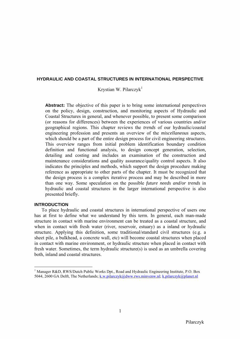
When discussing the subject of coastal structures, it is useful to indicate briefly the type of structures and their terminology, and where coastal structures play a role in the marine technology (see Figure 1).
Fig. 1a. Classification of coastal structures (SPM, 1984)
Pilarczyk
3
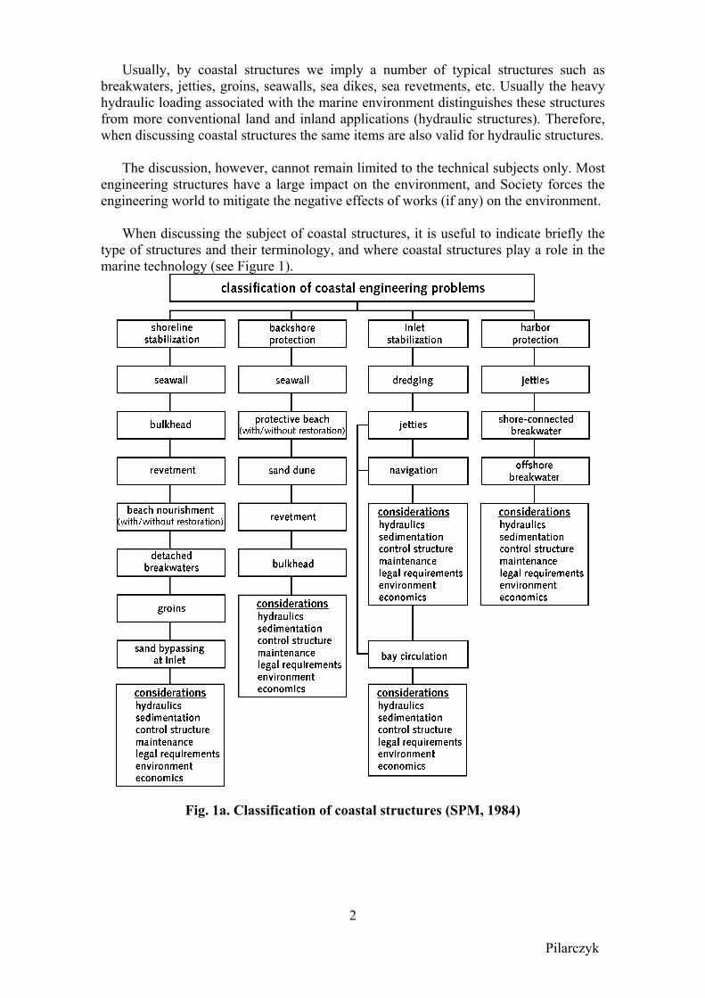
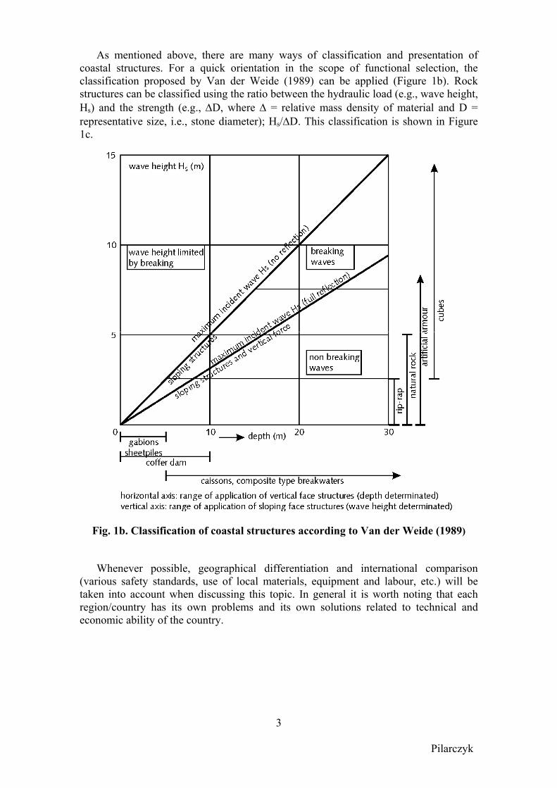
As mentioned above, there are many ways of classification and presentation of coastal structures. For a quick orientation in the scope of functional selection, the classification proposed by Van der Weide (1989) can be applied (Figure 1b). Rock structures can be classified using the ratio between the hydraulic load (e.g., wave height, Hs) and the strength (e.g., ∆D, where ∆ = relative mass density of material and D = representative size, i.e., stone diameter); Hs/∆D. This classification is shown in Figure 1c.
Fig. 1b. Classification of coastal structures according to Van der Weide (1989)
Whenever possible, geographical differentiation and international comparison (various safety standards, use of local materials, equipment and labour, etc.) will be taken into account when discussing this topic. In general it is worth noting that each region/country has its own problems and its own solutions related to technical and economic ability of the country.

Pilarczyk
4
Fig. 1c. Classification of rock structures using Hs/∆D-parameter (Van der Meer, 1988)
Pilarczyk
5
PROBLEM IDENTIFICATION AND DESIGN PROCESS In general, a coastal (or hydraulic) structure is planned as a practical measure to
solve an identified problem. Examples are seawalls and dikes, planned to reduce the occurrence of inundation due to storm surges and/or flooding, or a shore or bank protection structures to reduce erosion.
Coasts and banks appear in many landforms, yet all coasts and banks have one element in common: they form the transition between land and water. With the water being a dynamic element, it is clear that coasts or banks also act dynamically. The design of erosion control structures is one of the most challenging activity for an engineer because of multifunctional character and multidisciplinary interactions and responses namely, interaction between complex hydraulic loading, morphology, foundation (geotechnical aspects) and structural elements (stability) (Przedwojski et al., 1995). It should be stressed that the integrated, multifunctional and multidisciplinary approach to planning and design of hydraulic or coastal structures is still not yet a common approach. Even in the education process of engineers this approach is not always followed.
As indicated earlier, hydraulic and coastal structures are one of the means to solve a water management or a coastal problem. Coastal erosion is one of the most frequent coastal problems. Erosion of the part of the coast, which is often considered to be the most valuable part, viz., beach and dunes (or mainland), is an example of such a problem. To understand the problem and to find a proper control measure one must understand the hydraulic and morphological processes involved. Morphological processes cover those physical processes, which eventually result in the modification of the shape of a coast. The hydraulic and morphological processes in the coastal zone are governed by two primary phenomena, namely wind and tide. The winds are directly responsible for the generation of waves, currents and water-level fluctuations and as a result, for the transport of sand onshore and on the dry beach, while the tides express themselves in a periodic rising and falling of the water and in tidal currents. Strong winds result in extreme storm-surges and high waves, which are the dominant factor for structural stability of structures, flood protection, etc. They belong to “short” duration phenomena although the duration can be even in order of days.
Coastal erosion can be due to two fundamentally different processes (RIKZ, 2002):
(i) erosion during a severe storm surge, and/or (ii) structural erosion. Process (i) can be considered as a typical (often heavily, but temporary) redistribution phenomenon. Sand from the dunes and upper part of the beach is transported during the storm surge to deeper water and settles there. Under ordinary conditions, the sand will usually return partly to its pre-storm position. Assuming that there is no gradient in longshore transport, the total volume of sand between some limits of a dynamic cross-shore profile practically does not change due to the storm surge. Process (ii), structural erosion, is quite different from erosion due to a storm surge. This erosion is in most cases due to morphological gradients (mainly, gradients in longshore currents) along the coast. The volume of sand within a cross-shore profile reduces gradually with time. Without additional measures, the upper part of the profile (i.e. dune area) may also be lost
Pilarczyk
6
permanently. Changing the gradient in longshore current provides a way to reduce the erosion. When an erosion control scheme to a structural erosion problem is designed, one always needs to take into account the consequences of the selected alternative for the erosion process during storm surges.
The methods of interference differ from each other in a way they interfere with the coast. Where the hard methods aim at reducing the sediment transport along the coast or to try to contain the sand on the beach or in the dunes, beach nourishment merely supply sand which consequently will be eroded again. The latter implies that in most cases beach nourishments will have to be repeated regularly in order to protect an eroding coastline in the long term. When these beach nourishments can be reduced, for instance by applying offshore breakwaters, the investment of constructing the offshore breakwaters may be paid back by the (long term) reduction of the beach nourishments (CUR, 1997). All these factors must already be included in the design of project scheme.
There is still much misunderstanding on the use of dikes and seawalls and their possible disadvantages related to the disturbance of the natural coastal processes and even acceleration of beach erosion. However, it should be said that in many cases when the upland becomes endangered by inundation (as in The Netherlands, Bangladesh, Vietnam, and other countries) or by high-rate erosion (possible increase of sea-level rise) leading to high economical or ecological losses, whether one likes it or not, the dike or seawall can even be a 'must' for survival. The proper coastal strategy to be followed should always be based on the total balance of the possible effects of the counter measures for the coast considered, including the economical effects or possibilities. It is an 'engineering-art' to minimise the negative effects of the solution chosen (Kraus and Pilkey, 1988).
In general, designer has always to remember that an effective application of (hard) measures to stop or reduce the gradual erosion in the area under consideration always will result in a reduced input of sediments to the lee-side area. Often this reduced input leads to (increased) erosion in the lee-side area compared to the previous situation. Whether this is acceptable or not depends on the particular case. The lee-side consequences should always be taken properly into account in studying solutions for erosion problems (Pilarczyk, 1990, Pilarczyk and Zeidler, 1995). In conclusion, before making a final choice of a specific measure, the effectiveness and consequences of applying such a measure should be investigated with all available means. Some of these means (models) can give probably only a qualitative answer (show tendencies), but still can be a very useful tool in helping to take a right decision.
Substantial developments have taken place in hydraulic and coastal engineering design over recent years. These have been due principally to an improved scientific understanding of the river and coastal environment and to the development of better analytical and predictive techniques – particularly through mathematical modelling. Although a number of calculation methods have been developed and are applied, the mathematical description of the hydro-morphological processes and the consequent
Pilarczyk
7
quantitative assessment of the influence of structures on the behaviour of the coastline still are in a first stage. Further developing the description of these processes and incorporating them in computer programs will be required in order to have the tools available to design coastal structures and predict their impact more reliably. A number of promising attempts in this direction are already done in various research centres in Europe, USA and Japan (Van Gent, 1995, Hanson et al., 1996, Larson et al., 1997, Hsu et al., 1999). The closer international co-operation in this field is needed to accelerate these developments, including a proper validation using different geographical site data. However, from the viewpoint of coastal structures design (groins, offshore breakwaters, sea walls, etc.), considerable further developments will still be necessary before the design can be carried out on a fully analytical basis. Experience and engineering judgement still therefore form major elements of good design practice for hydraulic and coastal structures.
Despite of these new developments, a large number of new designs all over the world have not always been successful and the money spent on existing systems has not always yielded the anticipated benefits. As an example, inventory of functioning of groins applied along Dutch coast has indicated that about 50% of them do not fulfil the functional requirements, and sometimes even have an adverse effect. However, due to the relatively high investment involved, the designers and local authorities (to avoid to be blamed for a wrong choice) often defend a certain choice of insufficient or even non-functioning structures. But this wrong choice reflects often only a real state of our knowledge and not an inadequacy of a designer. There is an obvious need for guidelines on the use and effectiveness of coastal structure systems to assist engineers working in coastal engineering planning and management and to give them a basic understanding of design practice.
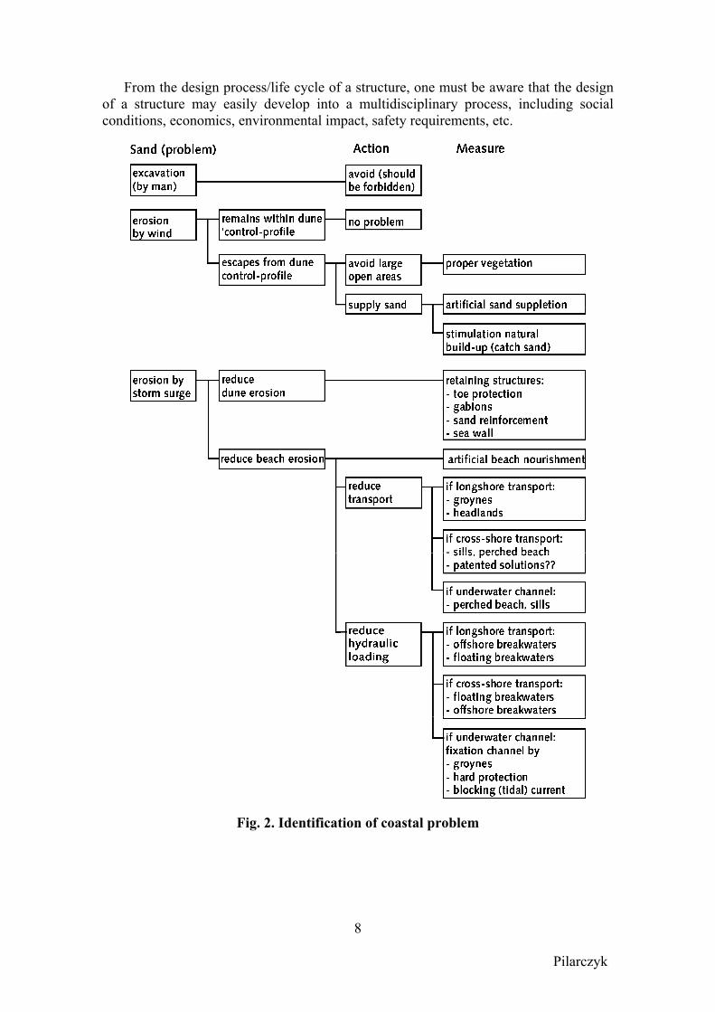
At the problem identification stage (see example in Figure 2), the presence of an existing or future problem is acknowledged and defined. The acknowledgement of an existing or future problem is generally accompanied by a determination to find an appropriate solution to that problem. In the context of this book, this solution will probably consist of a coastal or shoreline structure, bed protection, or any kind of maritime works. Future problems may be foreseeable as a result of predictable changes or may be generated by proposed engineering works. A simple example of the latter would be the need of protecting the down drift part of a planned shoreline protection (flank protection). Where several options exist, the preferred solution should always be determined as a result of cost/benefit analysis and consideration of environmental impact.
Starting with identification of the problem (e.g. inundation or shoreline erosion), a
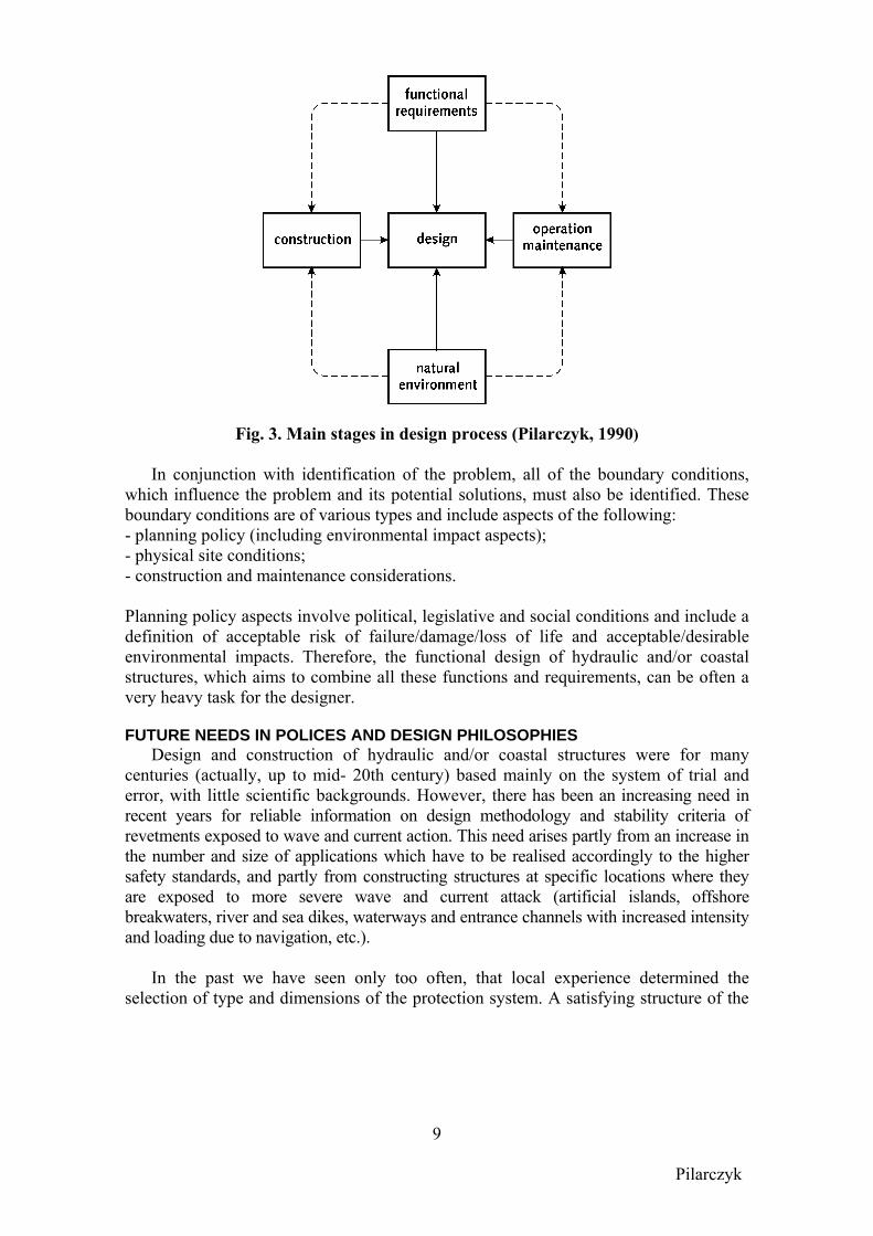
number of stages can be distinguished in the design process for (and life cycle of) a structure, the subsequent stages of which are determined by a series of decisions and actions cumulating in the creation of a structure (or structures) to resolve the problem. Post-design stages (to be considered during design!) are the construction and maintenance (monitoring and repair) of the structure and, finally, its removal or replacement. An overall formulation in flow chart form is given in Figure 3.
Pilarczyk
8
From the design process/life cycle of a structure, one must be aware that the design
of a structure may easily develop into a multidisciplinary process, including social conditions, economics, environmental impact, safety requirements, etc.
Fig. 2. Identification of coastal problem
Pilarczyk
9
Fig. 3. Main stages in design process (Pilarczyk, 1990)
In conjunction with identification of the problem, all of the boundary conditions, which influence the problem and its potential solutions, must also be identified. These boundary conditions are of various types and include aspects of the following: - planning policy (including environmental impact aspects); - physical site conditions; - construction and maintenance considerations. Planning policy aspects involve political, legislative and social conditions and include a definition of acceptable risk of failure/damage/loss of life and acceptable/desirable environmental impacts. Therefore, the functional design of hydraulic and/or coastal structures, which aims to combine all these functions and requirements, can be often a very heavy task for the designer. FUTURE NEEDS IN POLICES AND DESIGN PHILOSOPHIES
Design and construction of hydraulic and/or coastal structures were for many centuries (actually, up to mid- 20th century) based mainly on the system of trial and error, with little scientific backgrounds. However, there has been an increasing need in recent years for reliable information on design methodology and stability criteria of revetments exposed to wave and current action. This need arises partly from an increase in the number and size of applications which have to be realised accordingly to the higher safety standards, and partly from constructing structures at specific locations where they are exposed to more severe wave and current attack (artificial islands, offshore breakwaters, river and sea dikes, waterways and entrance channels with increased intensity and loading due to navigation, etc.).
In the past we have seen only too often, that local experience determined the
selection of type and dimensions of the protection system. A satisfying structure of the
Pilarczyk
10
neighbours was copied, although hydraulic loads and subsoil properties were different. This led to designs, which were unnecessarily conservative and consequently too costly, or were inadequate and thus leading to high maintenance costs. Actually, the technical feasibility and the dimensions of protective structures can easily be determined on a sounder basis and supported by better experience than in the past. Often, the solution being considered should still be tested in a scale model since no generally accepted design rules exist for all possible solutions and circumstances.
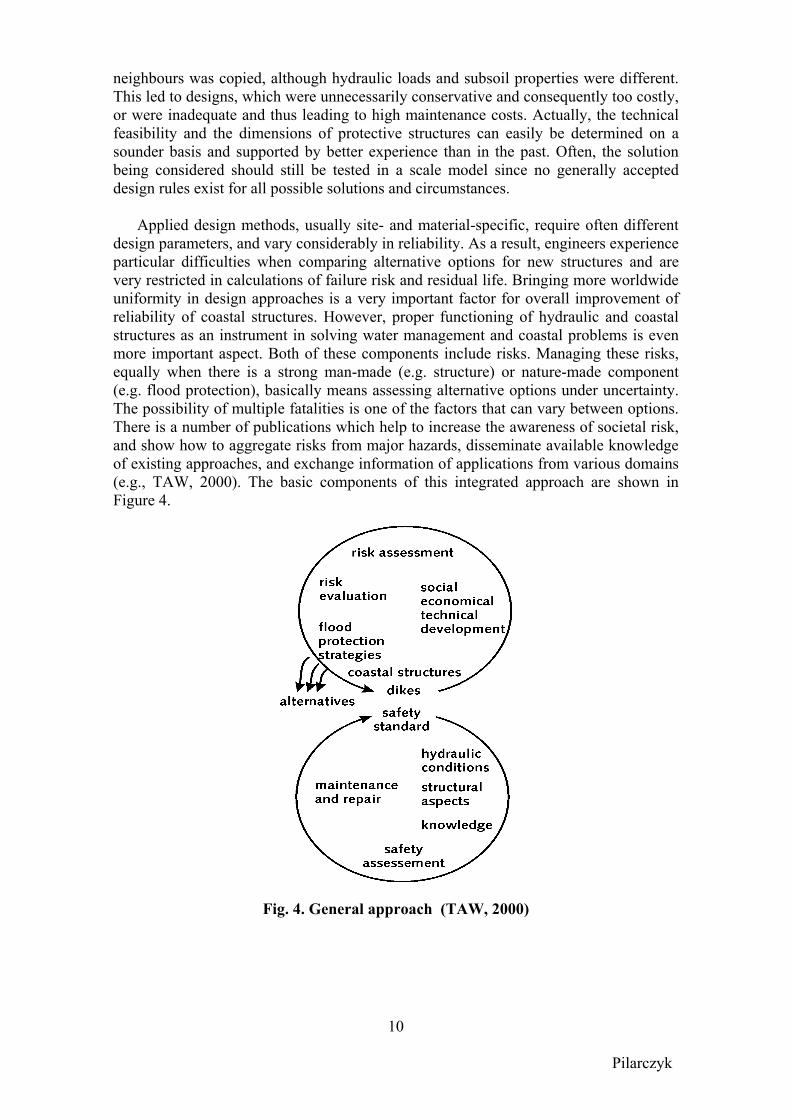
Applied design methods, usually site- and material-specific, require often different design parameters, and vary considerably in reliability. As a result, engineers experience particular difficulties when comparing alternative options for new structures and are very restricted in calculations of failure risk and residual life. Bringing more worldwide uniformity in design approaches is a very important factor for overall improvement of reliability of coastal structures. However, proper functioning of hydraulic and coastal structures as an instrument in solving water management and coastal problems is even more important aspect. Both of these components include risks. Managing these risks, equally when there is a strong man-made (e.g. structure) or nature-made component (e.g. flood protection), basically means assessing alternative options under uncertainty. The possibility of multiple fatalities is one of the factors that can vary between options. There is a number of publications which help to increase the awareness of societal risk, and show how to aggregate risks from major hazards, disseminate available knowledge of existing approaches, and exchange information of applications from various domains (e.g., TAW, 2000). The basic components of this integrated approach are shown in Figure 4.
Fig. 4. General approach (TAW, 2000)
Pilarczyk
11
This is very important when structures have to function as flood protection, especially for low-lying areas. The higher, stronger and more reliable the flood defences are, the lower the chance they will collapse. Reducing the possibility of consequent damage is the essential benefit of the level of safety inherent in the flood defences. To provide these benefits strengthening the flood defences demands major investment from society. This covers not only the money for flood construction and maintenance. In many cases such construction or improvement of the flood defence means damage to the countryside, natural life or local culture. The demands that are made on the level of protection against high waters also have to be based on balancing of social costs against the benefits of improved flood defences (Jorissen and Stallen, 1998). However, the balance between costs and benefits can also change as a result of changing social insights, at last but not at least, the actual occurrence of floods and flood damage, or the future climate change. To include all these aspects in the design, it is necessary to have the new design techniques cantered on risk-based approach.
In future practice, the results of (much) improved calculations should give rise to the discussion whether the local standards have to be increased (that means also further strengthening of flood defences or other risk reduction measures) in order to comply with existing standards for Group Risk or that the present situation is to be accepted as good practice. However, this discussion can only take place based on an extensive policy analysis. At present, such policy analysis cannot be fully drawn up yet. A lot of technical and non-technical data has to be collected and models have to be developed, but there are more than technical problems. This also implies the new requirements concerning the education of engineers and/or the need to work in multidisciplinary design teams.
Level of protection
Most design manuals are based on a deterministic design philosophy assuming a design water level and a design wave height of predicted return period (say 1 in 50 or 100 years), and the structure is designed to resist that event with an acceptable degree of safety. Probabilistic design methods, applied firstly on a large scale (in coastal engineering) during design and construction of the Eastern Scheldt Barrier in the Netherlands in 1980’s, are still not yet a common design philosophy in coastal engineering. However, their use is highly increasing in recent years in western countries. In probabilistic approach, the reliability of the structure is defined as the probability that the resistance of the structure exceeds the imposed loads. Extensive environmental (statistical) data is necessary if realistic answers are to be expected from a probabilistic analysis, and it is mainly for this reason that the procedures have not been frequently used in the past. However, the more uncertainty one has on environmental data and on structure response calculations, the more important it is to use a probabilistic approach. By using this approach one can estimate the uncertainties and their influence on the final result.
For the return period of environmental events used in the design of hydraulic and coastal structures, the actual value or values selected are generally considered both in relation to the level of protection required and the design life of the structure. Both have
Pilarczyk
12
an important bearing on the subsequent benefit cost study. Where high risk is involved and/or where scheme has a disproportionately high capital cost (i.e. flood barrier scheme, dikes protecting low-lying high density housing/population) extreme return periods of up to 1 in 1000 (or even 1 in 10000) years are chosen to ensure an adequate factor of safety. In case of projects of national importance (i.e. flood protection scheme), usually very costly, grant aid is sough from central government (or international aid agency), in which case agreement is reached early in the design through consultation with the appropriate authority. Design life
Existing Codes of Practice or Design Guidelines often provide some information on the minimum requirements for the design life of hydraulic and coastal structures (usually as 20 years for temporary or short term measures, 50 to 100 years for shore protection structures and 100 to 1000 years or more for flood prevention structures). However, the proper choice of return period should be carefully investigated base on type and required function of the structure. Also, the probabilistic approach allows to carryout the calculation with respect to cost optimization, which can be a reasonable base for the proper choice of the design return period. Whatever the level of protection, there is always a risk of damage by storms more extreme than the design event. Unless the structure is maintained in a good state of repair, the risk of damage is increased in time.
Similarly, the limitations in the serviceable life of some materials used in the
construction (i.e. concrete subject to abrasion, steel subject to corrosion, timber subject to deterioration, etc.) means that they cannot be expected to last the overall life of the structure and, repairs and replacement must be allowed for (must be planned for already in the design stage).
It is unrealistic to expect to design any hydraulic or coastal structure such that it will be free of maintenance or repair during its lifetime. Nevertheless, the ever-increasing requirement to minimise maintenance costs in line with some (national) economic restrictions has a considerable influence on the type of solution ultimately accepted. Cost optimization often shows that it is beneficial to use heavier rock (often only with a little increase of cost) than normally used in a rubble structure, to reduce the risk of damage suffered and so reduce the maintenance requirement (especially in case when mobilizing of material and equipment can be a problem). Conversely, where access and maintenance are relatively easy and where the result of failure is less serious, low capital-cost works are often an economical and acceptable solution.
To continue the functioning of the hydraulic or coastal structures during the prescribed lifetime, their renovation/rehabilitation will be usually needed. In general, in designing rehabilitation or upgrading works the engineer is restricted to a much more greater extent than in new works by the existing conditions. In some cases, complete demolition and reconstruction of the structure (or its part) can be considered as an optimum solution. The design of this type of works is primarily conditioned by the inadequacy of the previous structure to fulfil its original purpose or to meet the
Pilarczyk
13
requirements of a new and more demanding standard or new boundary conditions (i.e. due to the climate change). In some cases, the wrong functioning of the structure can be proved (i.e. a loss of beach in front of the sea wall). In such a case, a radically different type of structural solution may be evolved, which is more compatible with coastal (or river) processes and the needs of conservation and amenity, (for example, introduction of a shingle beach, sometimes in combination with a groin system, instead of a sea wall, as it was often applied in United Kingdom).
Failure modes and partial safety factors (based on Burcharth, 1999 and others)
For the majority of coastal (or hydraulic) structures, however, like breakwaters, groins and revetments, there seems to be no generally accepted safety or risk levels, and very few design standards comprise such structures. Prof. Burcharth, a driving force in Europe for reliability standards for breakwaters, made in 1999 an interesting attempt to discussion on the safety levels and ways of implementing them in the design procedure of breakwaters, at least in conceptual design stage. In this stage, we basically are evaluating alternative designs and it is of course important that we compare designs with equal functional performance and equal safety.
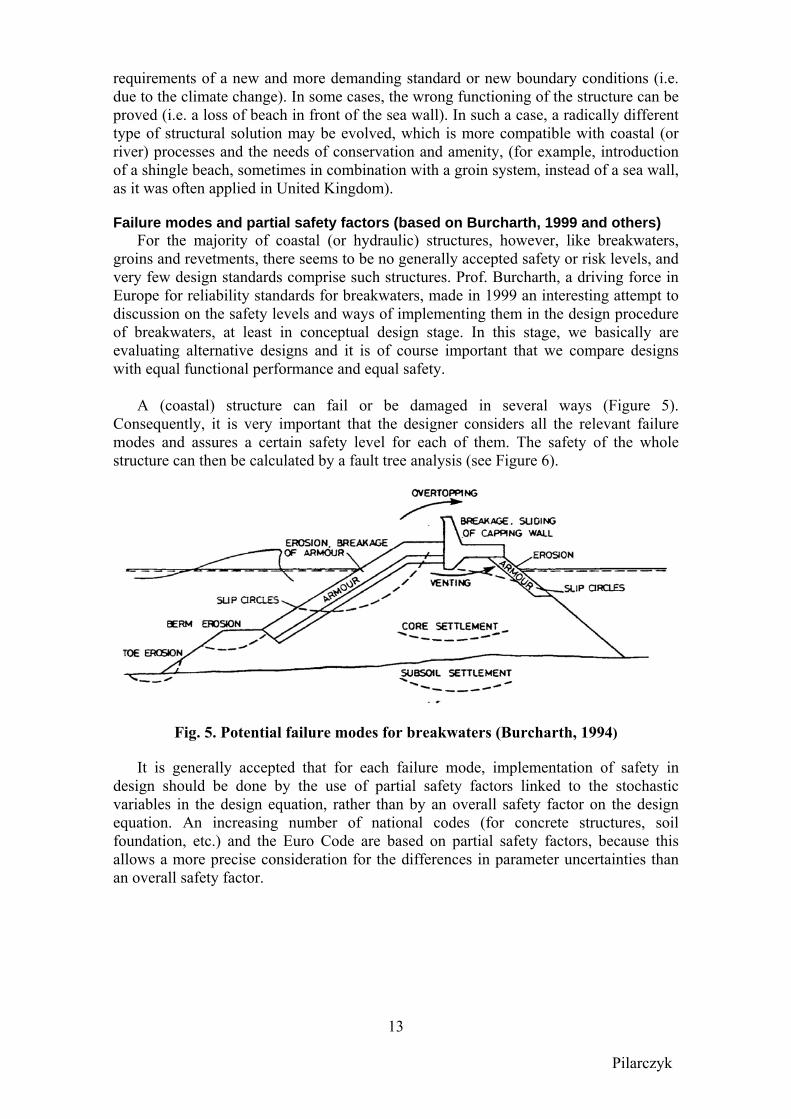
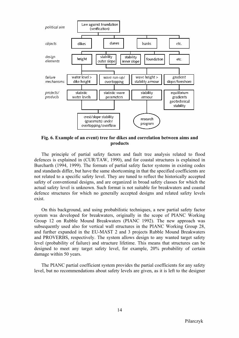
A (coastal) structure can fail or be damaged in several ways (Figure 5). Consequently, it is very important that the designer considers all the relevant failure modes and assures a certain safety level for each of them. The safety of the whole structure can then be calculated by a fault tree analysis (see Figure 6).
Fig. 5. Potential failure modes for breakwaters (Burcharth, 1994)
It is generally accepted that for each failure mode, implementation of safety in design should be done by the use of partial safety factors linked to the stochastic variables in the design equation, rather than by an overall safety factor on the design equation. An increasing number of national codes (for concrete structures, soil foundation, etc.) and the Euro Code are based on partial safety factors, because this allows a more precise consideration for the differences in parameter uncertainties than an overall safety factor.
Pilarczyk
14
Fig. 6. Example of an event) tree for dikes and correlation between aims and products
The principle of partial safety factors and fault tree analysis related to flood
defences is explained in (CUR/TAW, 1990), and for coastal structures is explained in Burcharth (1994, 1999). The formats of partial safety factor systems in existing codes and standards differ, but have the same shortcoming in that the specified coefficients are not related to a specific safety level. They are tuned to reflect the historically accepted safety of conventional designs, and are organized in broad safety classes for which the actual safety level is unknown. Such format is not suitable for breakwaters and coastal defence structures for which no generally accepted designs and related safety levels exist.
On this background, and using probabilistic techniques, a new partial safety factor system was developed for breakwaters, originally in the scope of PIANC Working Group 12 on Rubble Mound Breakwaters (PIANC 1992). The new approach was subsequently used also for vertical wall structures in the PIANC Working Group 28, and further expanded in the EU-MAST 2 and 3 projects Rubble Mound Breakwaters and PROVERBS, respectively. The system allows design to any wanted target safety level (probability of failure) and structure lifetime. This means that structures can be designed to meet any target safety level, for example, 20% probability of certain damage within 50 years.
The PIANC partial coefficient system provides the partial coefficients for any safety level, but no recommendations about safety levels are given, as it is left to the designer
Pilarczyk
15
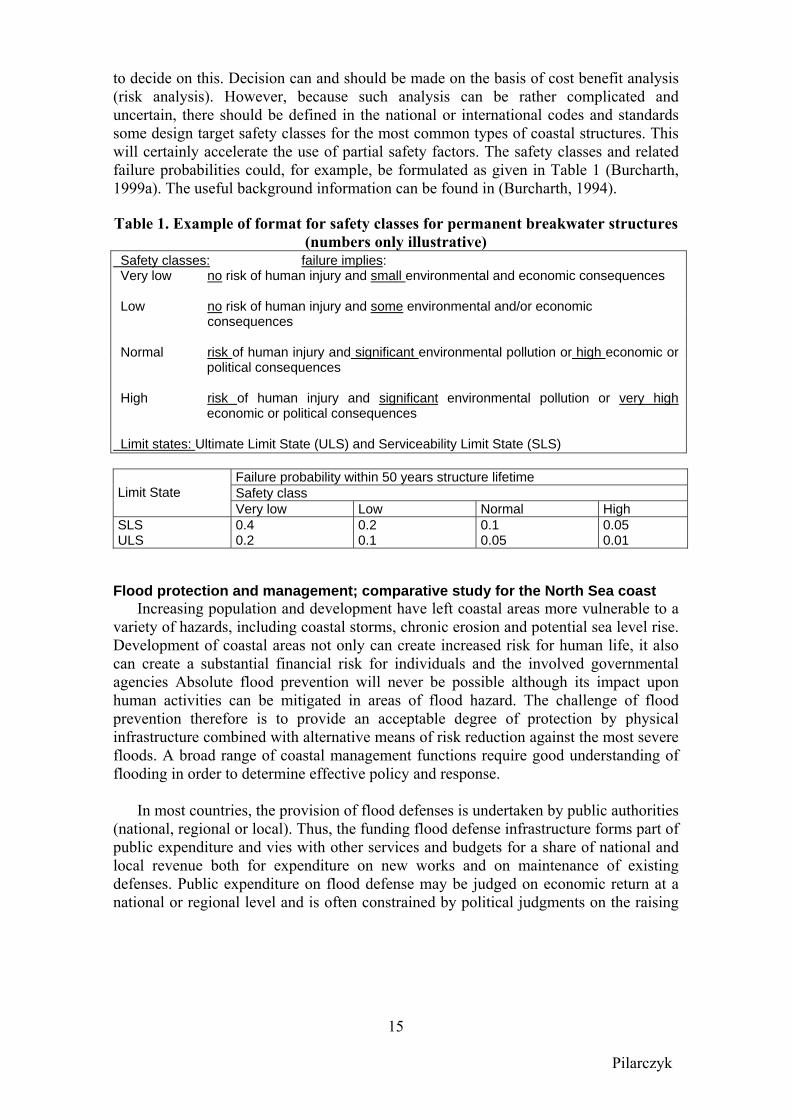
to decide on this. Decision can and should be made on the basis of cost benefit analysis (risk analysis). However, because such analysis can be rather complicated and uncertain, there should be defined in the national or international codes and standards some design target safety classes for the most common types of coastal structures. This will certainly accelerate the use of partial safety factors. The safety classes and related failure probabilities could, for example, be formulated as given in Table 1 (Burcharth, 1999a). The useful background information can be found in (Burcharth, 1994). Table 1. Example of format for safety classes for permanent breakwater structures
(numbers only illustrative) Safety classes: failure implies: Very low no risk of human injury and small environmental and economic consequences Low no risk of human injury and some environmental and/or economic consequences Normal risk of human injury and significant environmental pollution or high economic or
political consequences High risk of human injury and significant environmental pollution or very high
economic or political consequences Limit states: Ultimate Limit State (ULS) and Serviceability Limit State (SLS)
Failure probability within 50 years structure lifetime Safety class
Limit State
Very low Low Normal High SLS ULS
0.4 0.2
0.2 0.1
0.1 0.05
0.05 0.01
Flood protection and management; comparative study for the North Sea coast
Increasing population and development have left coastal areas more vulnerable to a variety of hazards, including coastal storms, chronic erosion and potential sea level rise. Development of coastal areas not only can create increased risk for human life, it also can create a substantial financial risk for individuals and the involved governmental agencies Absolute flood prevention will never be possible although its impact upon human activities can be mitigated in areas of flood hazard. The challenge of flood prevention therefore is to provide an acceptable degree of protection by physical infrastructure combined with alternative means of risk reduction against the most severe floods. A broad range of coastal management functions require good understanding of flooding in order to determine effective policy and response.
In most countries, the provision of flood defenses is undertaken by public authorities (national, regional or local). Thus, the funding flood defense infrastructure forms part of public expenditure and vies with other services and budgets for a share of national and local revenue both for expenditure on new works and on maintenance of existing defenses. Public expenditure on flood defense may be judged on economic return at a national or regional level and is often constrained by political judgments on the raising
Pilarczyk
16
and distribution of public finances. The time-scales for such political judgments are driven by many factors including public opinion, national and international economic cycles, etc. It may be argued that the provision of effective flood defense can become a “victim” of its own success, with increase pressure to reduce expenditure on flood defense when the defenses appear to remove the flood hazard and the impacts of the previous flooding recede in the public and institutional memories. Thus we may hypothesize a cyclic variation of flood hazard determined by responses to major flood events (Samuels, 2000). Superimposed upon this cycle will be increases in vulnerability from economic and social development within (coastal) flood plains and changes in the climatic forcing and hydrological response.
The problem of flooding is too complex for a complete review. However, there are a
large number of excellent publications where useful information on these problems and associated techniques can be found (CUR/TAW, 1990, Przedwojski et al., 1995, Meadowcroft et al., 1995, Vrijling, 1998, Jorissen and Stallen, 1998, Koch, 2000, Oumeraci, 2001). Also, as an example, the results of comparative studies on coastal flooding for some countries along the North Sea are presented below.
The countries along the North Sea coast enjoy both the advantages and disadvantages of this shared neighbour. All countries face the threat of coastal floods to some extent, although the potential consequences of a flooding disaster vary significantly. Each country has developed a system of flood protection measures according to the nature of the threat, potential damages, and its historical, social, political and cultural background. These measures may range from coastal zone planning to evacuation in emergency situations. In all cases, however, construction and maintenance of flood defence structures is the core of these measures.
Recently, the North Sea Coastal Management Group (NSCMG) has agreed to
conduct a joint study on the different approaches to safeguarding against coastal flooding. The primary goal of research is to improve communication between the various countries on this subject. The study is limited to coastal defence structures in the five participating countries, namely: Belgium, the United Kingdom, Germany, Denmark and the Netherlands (Jorissen et al., 2001).
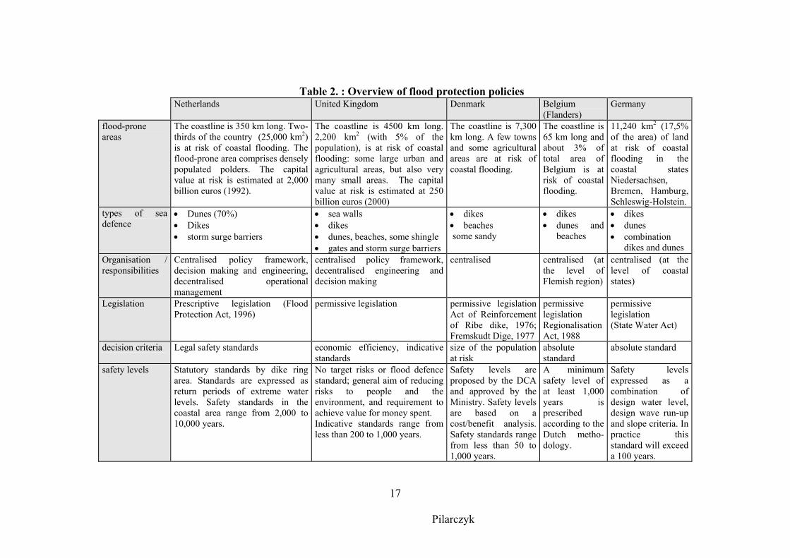
The safety offered by flood defence structures, generally expressed as return periods of extreme water levels, seems to vary quite a lot in the different countries. In the United Kingdom, no safety levels are prescribed. Indicative safety levels range from less than 200 years to 1,000 years. In The Netherlands, on the other hand, the legally prescribed safety standards range from 2,000 to 10,000 years. The return period of an extreme water level however, is only one indication of the actual safety provided by the flood defence structures. In practice, the applied data, design procedures, criteria and safety margins determine actual safety. In addition to all this, significant historical, social, cultural and political differences contribute to the variety of flood protection policies, especially with regard to the authorities involved and responsibilities. Table 2 compares some specific aspects of flood protection policies in the five countries.
Pilarczyk
17
Table 2. : Overview of flood protection policies Netherlands United Kingdom Denmark Belgium
(Flanders) Germany
flood-prone areas
The coastline is 350 km long. Two-thirds of the country (25,000 km2) is at risk of coastal flooding. The flood-prone area comprises densely populated polders. The capital value at risk is estimated at 2,000 billion euros (1992).
The coastline is 4500 km long. 2,200 km2 (with 5% of the population), is at risk of coastal flooding: some large urban and agricultural areas, but also very many small areas. The capital value at risk is estimated at 250 billion euros (2000)
The coastline is 7,300 km long. A few towns and some agricultural areas are at risk of coastal flooding.
The coastline is 65 km long and about 3% of total area of Belgium is at risk of coastal flooding.
11,240 km2 (17,5% of the area) of land at risk of coastal flooding in the coastal states Niedersachsen, Bremen, Hamburg, Schleswig-Holstein.
types of sea defence
• Dunes (70%) • Dikes • storm surge barriers
• sea walls • dikes • dunes, beaches, some shingle • gates and storm surge barriers
• dikes • beaches some sandy
• dikes • dunes and
beaches
• dikes • dunes • combination
dikes and dunes Organisation / responsibilities
Centralised policy framework, decision making and engineering, decentralised operational management
centralised policy framework, decentralised engineering and decision making
centralised centralised (at the level of Flemish region)
centralised (at the level of coastal states)
Legislation Prescriptive legislation (Flood Protection Act, 1996)
permissive legislation permissive legislation Act of Reinforcement of Ribe dike, 1976; Fremskudt Dige, 1977
permissive legislation Regionalisation Act, 1988
permissive legislation (State Water Act)
decision criteria Legal safety standards economic efficiency, indicative standards
size of the population at risk
absolute standard
absolute standard
safety levels Statutory standards by dike ring area. Standards are expressed as return periods of extreme water levels. Safety standards in the coastal area range from 2,000 to 10,000 years.
No target risks or flood defence standard; general aim of reducing risks to people and the environment, and requirement to achieve value for money spent. Indicative standards range from less than 200 to 1,000 years.
Safety levels are proposed by the DCA and approved by the Ministry. Safety levels are based on a cost/benefit analysis. Safety standards range from less than 50 to 1,000 years.
A minimum safety level of at least 1,000 years is prescribed according to the Dutch metho-dology.
Safety levels expressed as a combination of design water level, design wave run-up and slope criteria. In practice this standard will exceed a 100 years.
Pilarczyk
18
MANUALS AND CODES Unlike the majority of engineering designs, the design of hydraulic and/or coastal
works is not always regulated or formalised by codes of practice or centralised design and construction. In some countries (e.g. Japan, China) the design of hydraulic and coastal structures is based upon a national code of practice, but usually it is based upon a design manual or standardised design guidelines. Such publications may have mandatory effect or be simply advisory. Design Codes of Practice are more useful for less developed countries (or countries with less maritime engineering tradition) where, due to a certain arrears in technological development, too much freedom can lead to the unreliable designs. However, such design codes must be prepared by experts (or at least verified by experts) and periodically upgraded. In general, it should be recommended to upgrade the codes every five years.
In Europe, most countries are using design guidelines instead of design code. A
formal code of practice (or a strict formalised design manual) are usually considered to be inappropriate for coastal engineering in view of the somewhat empirical nature of the present design process, the diversity of factors bearing on the design solution (often site dependent), and still the major role that engineering judgement and experience plays in the design process. The term ‘guidelines’ implies that guidance is given to the engineer responsible for planning and designing coastal structures in that steps in the design/planning process are described; and the considerations involved are discussed, alternative methodologies are set out and their present limitations explained. Usually these guidelines are officially formalized, but still they include a certain freedom in their use; designer may deviate from these guidelines when reasonable arguments are provided or when better (more recent) approved design techniques are used. In this way, designers can follow the actual worldwide developments.
The Netherlands probably provides the best example of construction and use of design guidelines. As a low-lying country, dependent on reliable water defence system, it requires high level of safety and thus, also reliable design and construction techniques. The responsible departments of the Dutch government, under supervision of the Technical Advisory Committee for Water Defences (TAW), have supported the production of a number of overall guidelines and Technical Reports giving guidelines on a general strategies and design philosophies, and on specific technical subjects. These guidelines cover not only the general design philosophy and methodology, but also technical details on failure modes and calculation methods (often developed in own research programs when not available, or not reliable enough on the market). These guidelines were often used as a reference by other countries (especially, countries around the North Sea) for establishment of their own guidelines. The usual period of upgrading these guidelines is about 5 years. There are national standards in the Netherlands on specification of materials (rock, concrete, timber, steel, geotextile, etc., which are gradually replaced by European Standards (EuroCodes).
In Germany, the Committee for Waterfront Structures has produced the design recommendations (EAU 1996, 2000). These are not mandatory regulations, and so can be simply up-dated annually if required. However, Germany is known as a country with a long standardisation tradition in civil engineering applications (German DIN’s); it concerns specifications and design methods in a wide range of various materials (concrete, steel, timber, geosynthetics, earthworks, etc.). Also, structural safety is
Pilarczyk
19
treated by one of these codes. Most of these codes will be actually replaced by Euro codes. When designing coastal structures or their components, reference is usually made to these DIN standards.
In the UK there is little centralised design or construction of coastal structures. In 1984, the British Standards Institution (BSI) issued a Code of Practice for maritime structures. This Code of Practice is not, however, intended to be of direct use in the design of coastal structures. While it considers some subject areas in detail, some other aspects of importance in the design of coastal structures receive very little attention and/or need updating. More information on organisational aspects (policy responsibility) and standards and technical guidelines in UK can be found in (Fowler and Allsop, 1999).
In Spain, design of coastal structures is regulated by a recent document: Recommendations for maritime structures, ROM 0.2-99. The ROM documents gather the leading state of the art knowledge, as well as the extensive experience in maritime engineering in Spain. The objective of the ROM is to define a set of RULES and Technical Criteria, that must be followed in the project design, operation, maintenance and dismantle of Maritime Structures, no matter the materials and methods used in each of the project stages. Concerning the structural safety, the ROM proposes different levels of reliability analysis, for each of the mutually exclusive and collectively exhaustive modes of failure, depending on the general and the operational nature of the maritime structure. Structures with small values of the “nature” (definition of the importance of structure and consequences of failure) can be verified with a “partial safety coefficient level”, while those with high nature values are enforced to be verified with the application of a Probabilistic Level II method. An overall procedure is set up in order to guide the designer to fulfil the recommendations prescribed in the program ROM. A software program has been written in order to help designers to follow the ROM. A new revised version of ROM is planned for 2002.
Japan is known as a country working with rather strict design standards. The history and recent developments on design standards for maritime structures in Japan are extensively outlined in the three papers at Coastal Structures’99 ( Takahashi et al., Mizuguchi et al., Yamamoto et al., 1999). Originally, depending on the designation and usage of a particular region, coasts were managed by four governmental agencies (construction, transport, fishery, and agriculture), each with its own standards and regulations. This situation was very confusing for everybody, especially because of different design approaches and criteria. Recently, the Ministry of Construction and the Ministry of Transport are combined to the new Ministry of Land, Infrastructure and Transport (MLIT) which fact clarifies the present coastal management situation in Japan. Actually, extensive revision of technical standards on coastal facilities is under way. Already in 1999, it was decided to revise the old ‘Technical Standards for Port and Harbour Facilities’ and ‘Design Standard of Fishing Port Facilities’ (see OCADI, 1999/2002). Following that, the Japanese Committee on Coastal Engineering is actually preparing Design Manual on Coastal Facilities, which will be a base for a new Japanese standard (Mizuguchi and Iwata, 1999). Also, the Japanese Coastal Act (dated from 1956), is under revision. The purpose of these revision activities is to harmonise the different approaches and to reflect progresses in coastal engineering from the recent years. The neutral body like Japanese Committee on Coastal Engineering is asked to
Pilarczyk
20
guide all these revision activities, and in this way to help to resolve the differences within the Ministries involved.
In United States, where the U.S. Army Corps of Engineers is responsible for many coastlines, the most frequently used guide is the Shore Protection Manual (SPM, 1984). This is not an official formalised national Design Code, but in practice it is treated in that way, especially within the U.S. Army Corps organization. This guide was a very modern tool in the 70’s and was used worldwide for the design of coastal structures. The advantage of this guide was its completeness, clear style and calculation examples. The disadvantage was its conservatism and limited upgrading in new editions; upgrading was only accepted when the faults become very evident or when much experience with some new techniques was gained, usually outside the U.S.A. As a result, the new design techniques developed often in US were at first applied in Europe or other countries where European consultants were active. Currently, SPM is being replaced by the new and updated Coastal Engineering Manual (CEM, 2002), which becomes a very modern guide reflecting latest developments and which, in combination with recent Manuals on Rock (CUR/CIRIA, 1991, CUR/RWS, 1995) can be recommended for worldwide use as reference.
It should be mentioned here that during the Coastal Structures’99 Conference, a special session on “Guidelines, Standards and Recommendations on Maritime Structures” was held. Speakers invited from different countries around the World (Denmark, France, Germany, Holland, Italy, Japan, UK, USA and Spain) were invited to present the state of the art and the level of development of guidelines in their respective countries. Also, the PIANC Safety Factor System for Breakwaters was discussed. From the presentations, it seems that a large variety of codes, manuals and guidelines with different scopes and objectives are now available; moreover, it is apparent that each country is writing their standards without too much connection with other countries. However, there are many similarities between these documents.
Concerning the structural safety, most of the standards are using the Method of the Limit States as a standard method for the verification of the failure modes. Many countries are still using overall safety factors, while others are developing or using partial safety factors. In order to facilitate the design of breakwaters to any target safety level, the PIANC PTC II Working Groups on breakwaters developed a system of partial safety factors corresponding to any wanted safety level which can be considered as a practical engineering way of using a probabilistic level II method. The PIANC “method” is independent as such of the level of environmental data quality. The partial safety factors given are related to the data quality (poor or good data sets). More details on this subject can be found in the Proceedings of this conference (Losada, ed., 1999). Future design requirements (codes)
Technical developments will always go on resulting in one or other way in further upgrading of our knowledge and improvement of our design standards. However, each new period brings some new elements and problems, which should explicitly be taken into account and planned in more structural way. The type of design that will need to be undertaken in the 21st century will reflect on one side the type and magnitude of existing work including their ageing and continuing deterioration, which is seen to be mainly in the field of upgrading, extension, rehabilitation and maintenance (CIRIA, 1986). On the other side, the new problems arising due to the long-term changes affecting the coastal
Pilarczyk
21
regimes, such as the structural erosion in front of coastal structures and the trend towards rising sea levels, steeping of foreshores, land subsidence and continue reduction of sediment supply from the rivers. Some new flood elevation schemes in low-lying areas will probably be required due to new safety standards.
The upgrading and extension of existing structures to meet new defence standards may require the engineer to determine the structural stability of the existing structures in order to determine whether the increased loading is capable of being accommodated. To support the engineer in his new task, new techniques for safety assessment and new criteria for dealing with upgrading of existing structures should be developed. In this respect, the ability to benefit from lessons learnt from the previous works is of paramount importance. The Dutch guide on safety assessment of dikes can be seen as an example of such development (Pilarczyk, 1998, TAW, 1996)
Taking a long-term view, the nature of the requirements will partly depend on the increasing demands that might be made on the coastline due to the continuing upward trend in leisure pursuits, or a greater emphasis on conservation (CIRIA, 1986). Such development may well necessitate a radical change of strategy in coastal defences but it is impossible to predict the type of changes that may result. However from the viewpoint of design, it is already recognised that there is a need to consider coastal engineering strategy over much greater lengths of coastline and over a longer period than at present. Some examples in this direction can be found in the Netherlands (RWS, 1990, TAW, 2000) and in UK (MAFF, 1997, 2000).
Strategic planning on this scale would be helped, if a comprehensive and detailed database of all the existing hydraulic and coastal defences all over the world existed. National authorities and international organisations should initiate some actions for development of such a database (including the lessons learnt from failures) and preparing new guidelines. The state-of-the-art review, which follows, should be based on (international) discussion with design engineers, contractors, research scientists and administrators to present a balanced presentation of a wide range of views. These guidelines should set out the state of the art in each subject area and comment on limitations in actual knowledge.
The introduction of (internationally recognised) guidelines should bring about an increase of reliability (reduction of risk) and a (possible) reduction in the overall cost to the nation of works by (CIRIA, 1986): - helping the designer to identify the most effective design solution; - improving the overall level of design practice, so as to reduce the number and cost of
over-designed and under-designed works; - promoting common standards of planning and design, thus improving the
effectiveness and co-ordination of coastline control nationally.
The future guidelines should serve a valuable role in setting out a common framework for future planning and design, and for helping to identify the most effective of a number of alternative design approaches with reference to the differences in geographical conditions and economic developments (abilities). Production of the guidelines must not reduce the need to carry out further research into the key areas of design but in opposite, it should stimulate a new research in areas where our knowledge
Pilarczyk
22
is still limited. Moreover, not all situations can be covered by guidelines, which refer more to standard cases, and there will always be need for additional research (i.e. model investigation) for special problems and high-risk projects. In order to maintain an overall coherence, the design guidelines should be reviewed (internationally) periodically (say, every 5 to max. 10 years) to introduce the advances in the state-of-the-art, and incorporate new experience. DESIGN TECHNIQUES
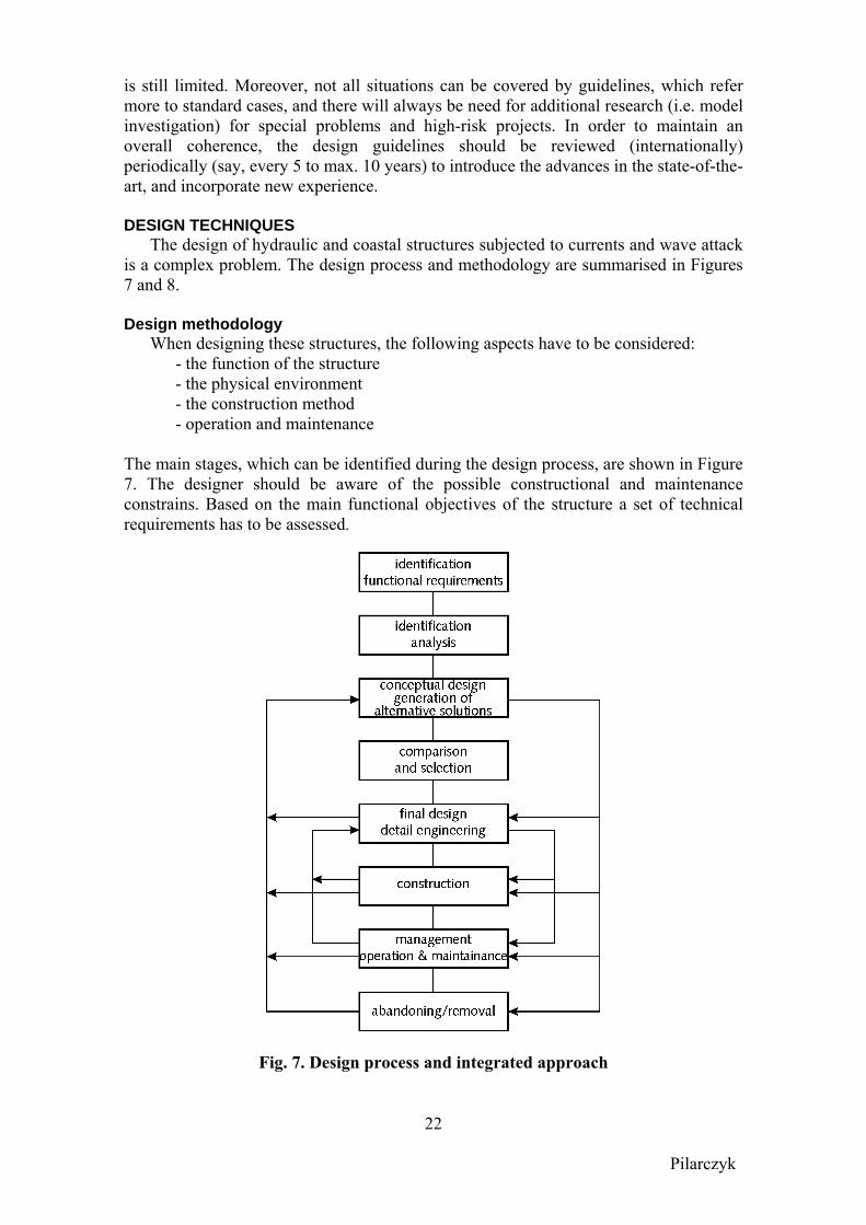
The design of hydraulic and coastal structures subjected to currents and wave attack is a complex problem. The design process and methodology are summarised in Figures 7 and 8. Design methodology
When designing these structures, the following aspects have to be considered: - the function of the structure - the physical environment - the construction method - operation and maintenance The main stages, which can be identified during the design process, are shown in Figure 7. The designer should be aware of the possible constructional and maintenance constrains. Based on the main functional objectives of the structure a set of technical requirements has to be assessed.
Fig. 7. Design process and integrated approach
Pilarczyk
23
When designing a hydraulic or a coastal structure (dike, seawall), the following requirements to be met can be formulated: 1. the structure should offer the required extent of protection against flooding at an
acceptable risk, 2. events at the dike/seawall should be interpreted with a regional perspective of
the coast, 3. it must be possible to manage and maintain the structure, 4. requirements resulting from landscape, recreational and ecological viewpoints
should also be met when possible, 5. the construction cost should be minimised to an acceptable/responsible level, 6. legal restrictions.
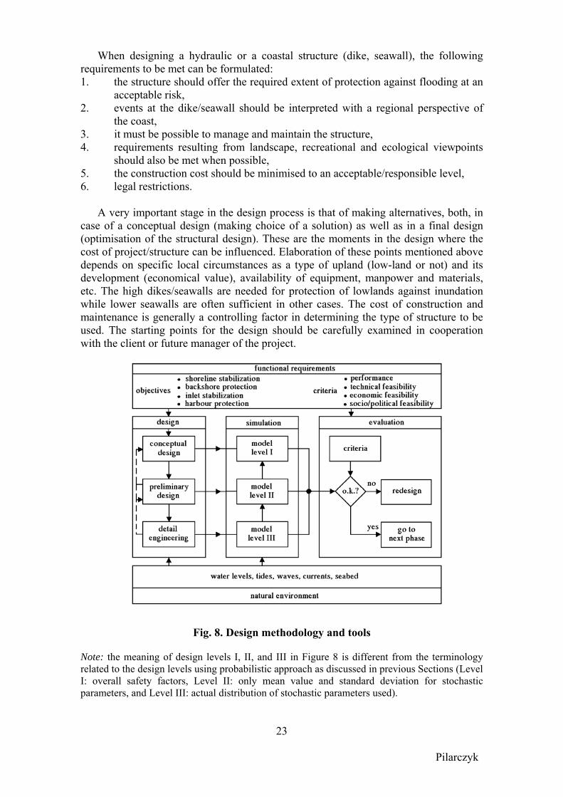
A very important stage in the design process is that of making alternatives, both, in case of a conceptual design (making choice of a solution) as well as in a final design (optimisation of the structural design). These are the moments in the design where the cost of project/structure can be influenced. Elaboration of these points mentioned above depends on specific local circumstances as a type of upland (low-land or not) and its development (economical value), availability of equipment, manpower and materials, etc. The high dikes/seawalls are needed for protection of lowlands against inundation while lower seawalls are often sufficient in other cases. The cost of construction and maintenance is generally a controlling factor in determining the type of structure to be used. The starting points for the design should be carefully examined in cooperation with the client or future manager of the project.
Fig. 8. Design methodology and tools Note: the meaning of design levels I, II, and III in Figure 8 is different from the terminology related to the design levels using probabilistic approach as discussed in previous Sections (Level I: overall safety factors, Level II: only mean value and standard deviation for stochastic parameters, and Level III: actual distribution of stochastic parameters used).
Pilarczyk
24
This design methodology is shown schematically on Figure 8, including also various simulation models (design tools) required to evaluate the behaviour of the structure in the various stages of design (Van der Weide, 1989, Pilarczyk, 1990). In general, it can be stated that in the course of the design-process more advanced methods are used. The actual choice, however, is dependent on the complexity of the problems, the size of the project and the risk-level, which is acceptable.
Depending on the objective, simulation can vary from crude approximations and rules of thumb (usually applicable at level I/conceptual design), through accepted empirical design formulae with their limitations (usually applicable at level II/preliminary design), to sophisticated reproductions of reality, using physical models, analogue techniques or numerical models (usually applicable at level III/final detail engineering). This kind of methodology should be followed both, in a case of functional design as well as in case of structural design. Examples of level I tools (rules of thumb) and level III tools (models) are presented below. Level II tools can be found on the websites: http://ihe.nl/we/dicea/cress.htm or http://www.cress.nl (CRESS-program). Level I Tools (Rules of Thumb)
Some examples of rules of thumb (tools for first estimate) are given below. a) Stability of revetments under wave attack
s0.5p
cosH ; (ctg 2)D
F α αξ
≤ ≥∆
(1)
with ξp= breaker similarity index on a slope; ααξ tan.H.T 1.25 = )L/H( tan= -0.5
sp-0.5
osp p , Hs = significant wave height, ∆ = relative mass density of units, D = thickness of cover layer (= Dn50 for stone), α = angle of slope, F = 2 to 2.5 for rock, = 3 for pitched stone, = 4 to 5 for place blocks, = 5 to 6 for interlocked blocks and cabled block mats. b) Maximum (depth-limited) wave height
Hs,max = (0.5 to 0.6) h (2) where h is the local depth. More precisely: use Goda’s graphs (Goda, 1985) or ENDEC: http://www.cress.nl c) Current attack:
g
UD2
2
=∆ (3)
where U is the depth-average velocity and g is the gravity. Multiply (3/4)D for a uniform flow and (3/2)D for a non-stationary, turbulent flow. d) Scour depth (hscour) and length of toe protection (Ltoe prot.)
hscour ≅ Hs and Ltoe prot ≥ 2 hscour (4) where Hs is the local wave height
Pilarczyk
25
e) Minimum length of protection of crest/splash area
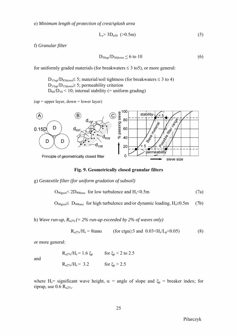
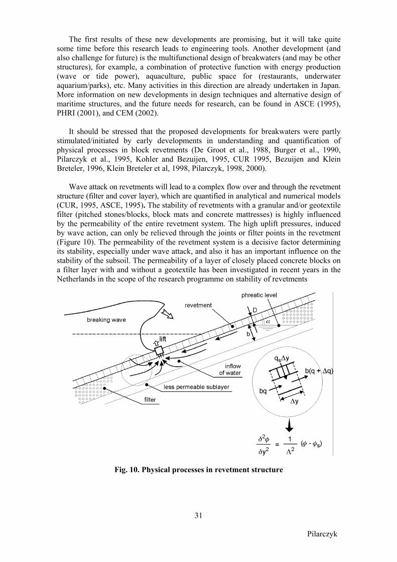
Ls> 3Dn50 (>0.5m) (5) f) Granular filter
D50up/D50down < 6 to 10 (6) for uniformly graded materials (for breakwaters ≤ 3 to5), or more general:
D15up/D85down≤ 5; material/soil tightness (for breakwaters ≤ 3 to 4) D15up/D15down≥ 5; permeability criterion
D60/D10 < 10; internal stability (= uniform grading) (up = upper layer, down = lower layer)
Fig. 9. Geometrically closed granular filters g) Geotextile filter (for uniform gradation of subsoil)
O90geot< 2D90base for low turbulence and Hs<0.5m (7a)
O90geot≤ D90base for high turbulence and/or dynamic loading, Hs≥0.5m (7b) h) Wave run-up, Ru2% (= 2% run-up exceeded by 2% of waves only)
Ru2%/Hs = 8tanα (for ctgα≥3 and 0.03<Hs/Lp<0.05) (8) or more general: Ru2%/Hs = 1.6 ξp for ξp < 2 to 2.5 and Ru2%/Hs = 3.2 for ξp > 2.5 where Hs= significant wave height, α = angle of slope and ξp = breaker index; for riprap, use 0.6 Ru2%.
Pilarczyk
26
Level III tools (models) Knowledge of the relevant wave climate is crucial to the design and construction of
coastal structures (do remember: rubbish in rubbish out). Good reliable data measured over a long period is rarely available; and in many cases limitations of time and/or cost do not permit such data to be obtained. The alternative is to derivate long-term estimates of wave climate by hindcasting on the basis of wind data. Special attention still deserves the prediction of wave climate in areas exposed to hurricanes, typhoons, and tsunamis, especially for countries, which do not have own (proper equipped) forecasting services.
An essential parameter in the design of hydraulic or coastal structures is the
probability of occurrence of severe events (high water levels, high waves). The design procedure based on the probabilities of water levels alone plus appropriate wave height is presently widely applied. However, this procedure does not reflect the full picture, as it does not allow for the possible correlation between the various parameter causing extreme events (tide, surge magnitude, wind direction, wave height and period). For an optimum design the joint probability of all these parameters should be taken into account. A number of recent manuals and guidelines have included this as a recommended approach; however, its application needs more detailed statistical data and correlations, and probabilistic calculation methods. (CUR/TAW, 1990, CUR/CIRIA, 1992, PIANC, 1992, CEM, 2002). Further developments in this direction should be stimulated, especially concerning the more user-friendly programs for re-working of statistical data into the required full joint design probability.
The next important design activity is to transfer the ‘offshore’ wave conditions into shallow water. Actually, the most frequently used methods are 1-D models as developed by Goda and by Battjes&Janssen (ENDEC-model). This item is currently the subject of the further improvement of a number of computer programs of various levels of sophistication. The most advanced method is at this moment probably the SWAN-model (Simulating Waves Nearshore), which was developed by the Technical University of Delft in the Netherlands and is a public domain model (Booij et al., 1996). However, even this model still needs further validation under various conditions. Shallow foreshores considerably affect wave propagation and hence wave impact and run-up on coastal structures. This concerns for instance the evolution of wave height distributions and wave energy spectra between deep water and the toe of coastal structures
As it was already mentioned, there are a number of models available. As an example, two numerical models have been applied in recent studies in the Netherlands to model the wave propagation over the foreshore and one numerical model has been applied to model wave motion on the structure (Van Gent and Doorn, 2001). The models applied for wave propagation over the shallow foreshore are a spectral wave model (SWAN; Ris, 1997 and Ris et al., 1998) and a time-domain Boussinesq-type model (TRITON; Borsboom et al., 2000, 2001). The model applied for modelling wave motion on the structure is a time-domain model based on the non-linear shallow-water wave equations (ODIFLOCS; Van Gent, 1994, 1995). SWAN model simulates propagation of short waves. It does not model processes where bound low-frequency energy becomes free due to wave breaking, which is a relevant process for situations with shallow foreshores. For the modelling of wave breaking (depth-induced wave breaking and white capping), wave set-up, bottom friction and triad wave-wave interaction the default settings were
Pilarczyk
27
used. The applied Boussinesq-type model is the two-dimensional wave model for wave propagation in coastal regions and harbours TRITON (WL | Delft Hydraulics), which is described in Borsboom et al. (2000, 2001). This efficient model simulates wave propagation and wave breaking in the time-domain, which also allows for simulation of processes where bound low-frequency energy becomes free due to wave breaking. This is a relevant process for situations with shallow foreshores. Wave breaking was implemented based on a new method where wave breaking is modelled as an eddy-viscosity model in combination with a surface roller, similar to the method applied by Kennedy et al. (2000). For the determination of the eddy viscosity use is made of the concept of surface rollers, as also applied by Schäffer et al. (1992). In contrast to many other existing models for wave breaking, this breaker model in TRITON allows for modelling of more severe wave breaking, as is the case in the discussed applications.
The general impression from examining the wave energy spectra is that the time-domain model simulates both the spectral shapes and the energy levels rather accurately for the conditions with significant energy dissipation due to severe wave breaking. Also the energy shift to the lower frequencies is modelled surprisingly well. The accuracy of the predictions for the wave periods is higher than obtained with the spectral wave model, though at the cost of higher computational efforts. The model is considered as suitable to provide estimates of the relevant parameters for wave run-up and wave overtopping on dikes with shallow foreshores.
For wave interaction with a dike the model applied here is the time-domain model ODIFLOCS (Delft University of Technology) which simulates wave motion on coastal structures (Van Gent, 1994, 1995). Perpendicular wave attack on structures with frictionless impermeable slopes is simulated by solving the non-linear shallow-water wave equations. Steep wave fronts are represented by bores. Use is made of an explicit dissipative finite-difference scheme (Lax-Wendroff), (Hibberd and Peregrine, 1979). Similar models have been shown to predict well wave reflection and wave run-up on impermeable rough slopes (Kobayashi et al, 1987).
Based on the investigations described in this paper the following conclusions can be drawn:
The spectral wave model, applied for wave propagation of short waves over the foreshore (SWAN), yields valuable insight in the evolution of wave energy spectra over the foreshore. It also shows that the computed energy levels in the short waves are rather accurately predicted, considering the rather extreme energy dissipation in the tests. The wave parameters Hm0 and Tm-1,0 at the toe of the structure are both under predicted (13% and 21% respectively), using the default settings of this numerical model. Modifications of the numerical model settings for this kind of applications might improve the results. Further improvements of this model could be dedicated to decrease wave energy transfer to higher frequencies and to increase wave energy transfer to lower frequencies.
The time-domain wave model applied for wave propagation over the foreshore (TRITON) shows accurate results for the wave parameters Hm0 and Tm-1,0 at each position. The deviations at the toe of the structure remain below 10% and 5% respectively (based on the energy in the short waves). The evolution of the wave energy spectra is rather accurately simulated despite the extreme energy dissipation. Also the
Pilarczyk
28
energy transfer to lower frequencies is clearly present. The model to include wave breaking in this Boussinesq-type model appears to be effective in reducing the wave energy without significant loss of accuracy in the simulation of wave energy spectra. Further validations of this model include 2DH-situations with angular wave attack, directional spreading and non-uniform depth-contours.
The time-domain wave model applied for the simulation of wave interaction with the dike (ODIFLOCS) shows that accurate results on wave run-up levels can be obtained if use is made of measured surface elevations of the incident waves (on average 10% under predictions of the wave run-up levels). The use of incident waves based on numerical results from the spectral wave model (SWAN) doubles the mean differences (18%) because both numerical models lead to too much wave energy dissipation. The use of incident waves calculated by the time-domain wave model (TRITON) reduces the differences significantly (on average less than 3%) because the numerical models lead to counteracting errors. Applying the two models together led to relatively accurate predictions of the wave run-up levels for the present data set. Stability of cover layers; some examples
The sudden intensification of research on rubble mound breakwaters in the 80’s was triggered by several damage to a series of relatively new breakwaters (Sines in Portugal, Arzew in Algeria and Tripoli in Libya). Also a substantial number of damage cases in Japan led to review of existing design formulae and the development of the famous Goda’s formula for vertical breakwaters (Goda, 1985). It was evident that there were fundamental problems with our methods of designing rubble mound breakwaters. The failure of Sines, Arzew and Tripoli breakwaters are described in Burcharth (1987). The main causes of the failures were:
1) The relative decrease in armour unit strength with increasing size was not considered and/or taken into account. This was crucial for slender, complex types of armour units (Burcharth, 1980, 1987).
2) The second reason for the major failures of rubble mound breakwaters was underestimation of the wave climate.
3) The third reason was bad model testing with incorrect modelling of the structure and the seabed topography.
A lot of research on the strength of slender armour units followed these failures
resulting in strength-design formulae for Dolosse and Tetrapods by which one can estimate the tensile stresses as function of incident waves, size of the units and for (Dolosse) the waist ratio. The tensile strength can then be compared to the concrete tensile strength in order to estimate if breakage takes place or not. The formulae also provide the relative number of broken units given the wave climate, the size and the tensile strength of the concrete (Burcharth et al., 2000). The failures involving broken slender concrete units resulted in two trends:
a. return to bulky units like cubes, and b. development in stronger complex (multileg) units, still with hydraulic stability
higher than, for example, cubes. The Accropode is a result of this development.
These failures also stimulated research into concrete material strength problems related to armour units. For example, Burcharth (1984) studied fatigue for slender units. A thermal stress caused by temperature differences in the concrete during curing is a
Pilarczyk
29
problem related to large bulky units. Burcharth (1983, 1991, 1992) studied this problem theoretically and by full-scale experiments for Sines, and formulated some guidelines to avoid the problem. The introduction of a hole in Antifer cubes was a result of this work. The solution was necessary for casting large cubes in the very hot climate of Somalia (Burcharth, 1991).
All the older design were mostly based on (simplified) formula of Hudson dated from 50’s, which gained its popularity due to its simplicity and the status of US Army Corps. However, the problems with using this formula started in 70’s with introduction of random waves and the necessity of transformation of regular waves into irregular waves. In 80’s, the number of testing facilities and test results with random waves became so large that the necessity of new design formulas became evident. Note: the Hudson formula is still preferred in some countries, e.g. USA, for shallow water conditions.
The new research in 80’s provided more understanding of failure mechanisms and new more sophisticated formulae on stability and rocking of rubble mound structures and artificial armour units.
Formulae developed by Van der Meer (1988) by fitting to model test data, with some later modifications, became standard design formulations. However, the reason of this development was quite different than above mentioned. To explain this we have turn back to 70’th when the author was involved in Delta project, the largest project of damming tidal gaps in the Netherlands, following the necessary actions after flood disaster in 1953. The author has discovered at that time that there was little known on stability of cover layers under wave attack, and that the existing formulations (Hudson, Irribaren, Hedar) were not perfect. He was strengthened in his suspicion by research of John Ahrens, a brilliant researcher from US Corps of Engineers, who was probably too far ahead in time for a general acceptance. Even in his home organisation he never gained the recognition, as he deserved; his work was never mention in US Shore Protection Manual. Ahrens (1975) performed extensive tests on riprap stability and the influence of the wave period; the test were conducted in the CERC large wave tank (with regular waves). Pilarczyk (1983, 1984) continued to replot Ahrens’s data and obtained surprising similarity with the later design graph by Van der Meer (1988). This work by Ahrens and his later research on dynamic stability of reefs and revetments, together with work by van Hijum on gravel beaches (Van Hijum and Pilarczyk, 1982), were the reason for the author to prepare a proposals for a systematic research on static and dynamic stability of granular materials (rock and gravel) under wave attack. This program, commissioned early 80’s to the Delft Hydraulics, was successfully realized under direct guidance by Van der Meer in 1988.
The basic structure of the Van der Meer formula is such that the stability number H/∆D is expressed in terms of natural or structural boundary conditions, for example (the sample formula is valid for rock under plunging waves):
mn NSP
DHs
ξ12.6
2.018.0
50⎟⎟⎠
⎞⎜⎜⎝
⎛=
∆ (9)
Pilarczyk
30
in which: Hs = significant wave height, ∆ = relative mass density, Dn50 = nominal stone diameter, P = permeability coefficient representing composition of the structure, S = damage level, and ξm = surf similarity parameter (Iribarren number).
The work of Van der Meer is now generally applied by designers and it has considerably reduced (but not eliminated) the need to perform model experiments during design process. We have always to remember that each formula represents only a certain schematisation of reality. Moreover, as far as these formulas are based on experiments and not based on fully physical understanding and mathematical formulations of processes involved, each geometrical change in the design may lead to deviation in the design results, and to the need of performance of model investigation. Another advantage of the Van der Meer formulae over the formula of Hudson is the fact that the statistical reliability of the expression is given, which enables the designer to make a probabilistic analysis of the behaviour of the design (d’Angremond, 2001). Note: the statistical uncertainty analysis for almost all formulae (including Hudson) is given by Burcharth in CEM (2002).
Following the same philosophy, Van der Meer and others have modified and extended the formulae for the stability of rock to many other aspects of breakwater design such as stability of some artificial units, toe stability, overtopping and wave transmission. However, these latest formulae (overtopping and transmission) are still in very rudimentary stage and need further improvement and extension. It concerns especially such structures as submerged reefs with a wide crest where all design aspects (stability, transmission, and functional layout) are not understood properly yet. Some experience with these structures is obtained in Japan, however, the generally valid design criteria are still absent.
What has been said for slopes under wave attack is largely valid for slopes and horizontal bottom protection under currents. The designer has a number of black box design tools available, but the understanding of the contents of the black box is far from complete. Specifically when these black box design formulae are used in expert systems, one may in the end be confronted with serious mistakes. If an experienced designer still realises the shortcomings and limitations of the black box formula, the inexperienced user of the expert system can easily overlook the implication of it.
Although a reliable set of design formulae is available, the main challenge in the field of rubble mound structures is to establish a conceptual model that clarifies the physical background of it. This will require careful experimental work, measuring the hydrodynamic conditions in the vicinity of the slope and inside the breakwater. Burcharth et al. (1999c) studied the internal flow process in physical models at different scales and in prototype and developed a method for scaling of core material, thus minimizing scale effects on stability. Possibly, an intermediate step has to be taken by developing a 2-D mathematical model (often called “numerical flume”) that describes the pressures and flow field with sufficient accuracy, examples of such development can be found in (Van Gent, 1995, Troch, 2001, Itoh et al., 2001). Experimental work will also remain necessary to assess the influence of turbulence. A second challenge is a further exploring of the opportunity to use single instead of double armour layers and further modification of filter rules. This will lead to considerable savings.
Pilarczyk
31
The first results of these new developments are promising, but it will take quite some time before this research leads to engineering tools. Another development (and also challenge for future) is the multifunctional design of breakwaters (and may be other structures), for example, a combination of protective function with energy production (wave or tide power), aquaculture, public space for (restaurants, underwater aquarium/parks), etc. Many activities in this direction are already undertaken in Japan. More information on new developments in design techniques and alternative design of maritime structures, and the future needs for research, can be found in ASCE (1995), PHRI (2001), and CEM (2002).
It should be stressed that the proposed developments for breakwaters were partly stimulated/initiated by early developments in understanding and quantification of physical processes in block revetments (De Groot et al., 1988, Burger et al., 1990, Pilarczyk et al., 1995, Kohler and Bezuijen, 1995, CUR 1995, Bezuijen and Klein Breteler, 1996, Klein Breteler et al, 1998, Pilarczyk, 1998, 2000).
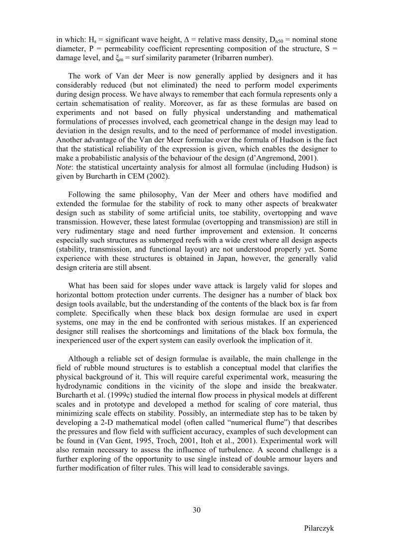
Wave attack on revetments will lead to a complex flow over and through the revetment
structure (filter and cover layer), which are quantified in analytical and numerical models (CUR, 1995, ASCE, 1995). The stability of revetments with a granular and/or geotextile filter (pitched stones/blocks, block mats and concrete mattresses) is highly influenced by the permeability of the entire revetment system. The high uplift pressures, induced by wave action, can only be relieved through the joints or filter points in the revetment (Figure 10). The permeability of the revetment system is a decisive factor determining its stability, especially under wave attack, and also it has an important influence on the stability of the subsoil. The permeability of a layer of closely placed concrete blocks on a filter layer with and without a geotextile has been investigated in recent years in the Netherlands in the scope of the research programme on stability of revetments
Fig. 10. Physical processes in revetment structure

Pilarczyk
32
The usual requirement that the permeability of the cover layer should be larger than that of the under layers cannot usually be met in the case of a closed block revetment and other systems with low permeable cover layer (i.e. concrete geomattresses). The low permeable cover layer introduces uplift pressures during wave attack. In this case the permeability ratio of the cover layer and the filter, represented in the leakage length, is found to be the most important structural parameter, determining the uplift pressure. The schematised situation can be quantified on the basis of the Laplace equation for linear flow (Figure 10). In the analytical model nearly all-physical parameters that are relevant to the stability have been incorporated in the "leakage length" factor. For systems on a filter layer, the leakage length Λ is given as:
Λ =bDk
k ' (10)
where: Λ = leakage length (m), D = thickness of the revetment cover layer (m), b = thickness of the filter layer (m), k = permeability of the filter layer or subsoil (m/s), and k’ = permeability of the top (cover) layer (m/s).
The pressure head difference, which develops on the cover layer, is larger with a large leakage length than with a small leakage length. This is mainly due to the relationship k/k' in the leakage length formula. The effect of the leakage length on the dimensions of the critical wave for semi-permeable revetments is apparent from the following equation:
⎟⎟⎠
⎞⎜⎜⎝
⎛
Λ∆ ξ op
0.67
scr Df = D
H (11)
where: Hscr = significant wave height at which blocks will be lifted out (m); ξop = tanα/√(Hs/(1.56Tp
2)) = breaker parameter (-); Tp = wave period (s); ∆ = relative mass density of cover layer = (ρs - ρ)/ρ, and f = stability coefficient mainly dependent on structure type and with minor influence of ∆, tanα and friction.
This research has proved that the stability of a revetment is dependent on the composition and permeability of the whole system. of the cover layer. Formulas have been derived to determine the permeability of a cover layer and filters, including a geotextile. Also, stability criteria for granular and geotextile filters were developed based on the load – strength principle, allowing application of geometrically open filters, and thus allowing optimisation of composition and permeability of revetments. It is obvious that only a certain force exceeding a critical value can initiate the movement of a certain grain in a structure. That also means that applying geometrically closed rules for filters often may lead to unnecessary conservatism in the design and/or limitation in optimisation freedom (see Figure 11). Also, it often results in execution problems especially when strict closed filter (with many layers) has to be executed under water under unstable weather conditions (Pilarczyk, 1994, Schiereck, 2001).
Pilarczyk
33
Fig. 11 Application of granular filters (Schiereck, 2001)
In the scope of these studies, also the internal strength of subsoil has been studied in terms of critical hydraulic gradients. It was recognised that to reduce the acting gradients below the critical ones a certain thickness of the total revetment is needed. This has resulted in additional design criteria on the required total thickness of revetment to avoid the instability of the subsoil. That also means that granular filter cannot always be replaced by geotextile only. For high wave attack (usually, wave height larger than 0.5m or high turbulence of flow) the geotextile functioning as a filter must be often accompanied by a certain thickness of the granular cushion layer for damping hydraulic gradients. All these design criteria can be found in Pilarczyk (2000).
The main problem in extension of these achievements to other applications (other
revetments, filter structures, bottom protection, breakwaters, etc.) is the lack of calculation methods on internal loads (i.e., hydraulic gradients) for different structural geometry and composition. Also the geometrically open filter criteria need further development. Research in these fields is still needed and will result in more reliable and cost effective designs. Verification of design
Not all hydraulic or coastal structures or their components are understood completely; moreover, the existing design techniques represent only a certain schematisation of reality. Therefore for a number of structures and/or applications the verification of design by more sophisticated techniques can still be needed.
Whilst certain aspects, particularly in the hydraulic field, can be relatively accurately predicted, the effect of the subsequent forces on the structure (including transfer functions into sublayers and subsoil) cannot be represented with confidence in a mathematical form for all possible configurations and systems. Essentially this means that the designer must make provisions for perceived failure mechanisms either by empirical rules or past experience. However, using this approach it is likely that the design will be conservative. In general, coastal structures (i.e. revetments, sea walls, etc.) are extended linear structures representing a high level of investment. The financial constraints on a project can be so severe that they may restrict the factors of safety arising from an empirical design. It is therefore essential from both the aspects of economy and structural integrity that the overall design of a structure should be subject
Pilarczyk
34
to verification. Verification can take several forms: physical modelling, full-scale prototype testing, lessons from past failures, etc.
Engineers are continually required to demonstrate value for money. Verification of a design is often expensive. However, taken as a percentage of the total costs, the cost is in fact very small and can lead to considerable long-term savings in view of the uncertainties that exist in the design of hydraulic and coastal structures. The client should therefore always be informed about the limitations of the design process and the need for verification in order to achieve the optimum design. MATERIALS AND SYSTEMS; SOME EXAMPLES
The cost of production and transportation of materials required for hydraulic and coastal structures is an important consideration when selecting a particular design solution. Thus it is important to establish the availability and quality of materials for a particular site at an early stage when considering design options. Using the available tools and models, the structure can be designed to perform the functional requirements. An additional problem is that these functions will change with time in service because of material degradation processes. Therefore the designer’s skill must also encompass consideration of durability and degradation processes. A degradation models for materials and structures should be developed so that the whole-life consequences may be considered at the design stage (NB. a provisional model for armour stone, which considered rock and environmental parameters, is presented in the CUR/CIRIA Manual (1991). Wastes and industrial by-products as alternative materials
Domestic and industrial wastes and industrial by-products form a still growing problem especially in high-industrialized countries or highly populated regions. A careful policy on application of these materials in civil engineering may (partly) help to reduce this problem. Current European policies aim to increase the use of waste materials of all kinds and to find economic, satisfactory and safe means of their disposal. The use of waste materials in hydraulic and coastal structures is limited by their particle size distribution, mechanical and chemical stabilities and the need to avoid materials which present an actual or potential toxic hazard (CUR/CIRIA, 1991, CUR/RWS 1995, Henneveld and Van der Zwan, 1997).
In the Netherlands, due to the lack of natural rock resources, the application of waste materials in civil engineering has already a long tradition. The extensive research on properties of waste materials allows making a proper selection depending on environmental requirements. Waste materials such as silex, quarry wastes, dredging sludge (depending on the source/location), and many minestone wastes have little or no hazardous contamination. These materials can be used as possible core, embankment fill or filter material. The engineering properties of many waste materials are often comparable or better than traditional materials. Slags have good friction properties due to their angularity and roughness and typically have high density. Mine wastes sometimes have poor weathering characteristics, but are usually inert and have satisfactory grading for deep fills. The fine materials such as fly ashes and ground slags are already in general use as cement replacement and fillers. Good quality control, not only for limiting the potential for toxic hazard, but also of the mechanical properties of waste materials can considerably increase the use of such low-cost materials in appropriately designed coastal and bank protection structures.
Pilarczyk
35
Geosynthetics and durability
Geosynthetics are relatively a new type of construction material and gained a large popularity especially in geotechnical engineering and as component for filter structures. There is a large number of types and properties of geosynthetics, which can be tailored to the project requirements (Pilarczyk, 2000). Geosynthetics have already transformed geotechnical engineering to the point that it is no longer possible to do geotechnical engineering without geosynthetics; they are used for drainage, reinforcement of embankments, reduction of settlement, temporary erosion control, and hazardous waste containment facilities (Giroud, 1987). These latest are very often planned as land reclamation along the shores.
When geosynthetic materials or products are applied in civil engineering, they are intended to perform particular functions for a minimum expected time, called the design life. Therefore, the most common (and reasonable) question when applying geosynthetics is ‘what is the expected/guaranteed lifespan of these materials and products’. There is no a straight answers to this question. Actually, it is still a matter of ‘to believe or not to believe’. Both the experimental theory and practice cannot answer this question yet. However, the Dutch evaluation of the long-term performance of the older applications of geotextiles (back to 1968) has proved that the hydraulic functioning was still satisfactory. A similar conclusion has been drawn from the recent evaluation of the long-term performance of nonwoven geotextiles from five coastal and bank-protection projects in USA (Mannsbart and Christopher, 1997).
The technology of geosynthetics has improved considerably in the years. Therefore, one may expect that with all the modern additives and UV-stabilizers, the quality of geosynthetics is (or can be, on request) much higher than in the 60s. Therefore, for the ‘unbelievers’ among us, the answer about the guaranteed design life of geosynthetics can be at least 50 years. For ‘believers’, one may assume about 100 years or more for buried or underwater applications. These intriguing questions on the lifespan of geosynthetics are the subject of various studies and the development of various test methods over the world. Also, the international agencies related to normalization and standardization are very active in this field. The recent guide (European Standard) of the European Normalization Committee presents the actual ‘normalized knowledge’ on this subject (CEN/CR ISO, 1998). The object of this durability assessment is to provide the designing engineer with the necessary information (generally defined in terms of material reduction or partial safety factors) so that the expected design life can be achieved with confidence. Geosystems
In recent years traditional forms of river and coastal works/structures have become very expensive to build and maintain. Various structures/systems can be of use in hydraulic and coastal engineering, from traditional rubble and/or concrete systems to more novel materials and systems such as geotextiles/geosynthetics, natural (geo)textiles, gabions, waste materials, etc. Moreover, there is a growing interest both in developed and developing countries in low-cost or novel engineering methods, particularly as the capital cost of defence works and their maintenance continue to rise. The shortage of natural rock in certain geographical regions can also be a reason for looking to other materials and systems. This all has prompted a demand for cheaper, less massive and more environmentally acceptable engineering. However, besides the
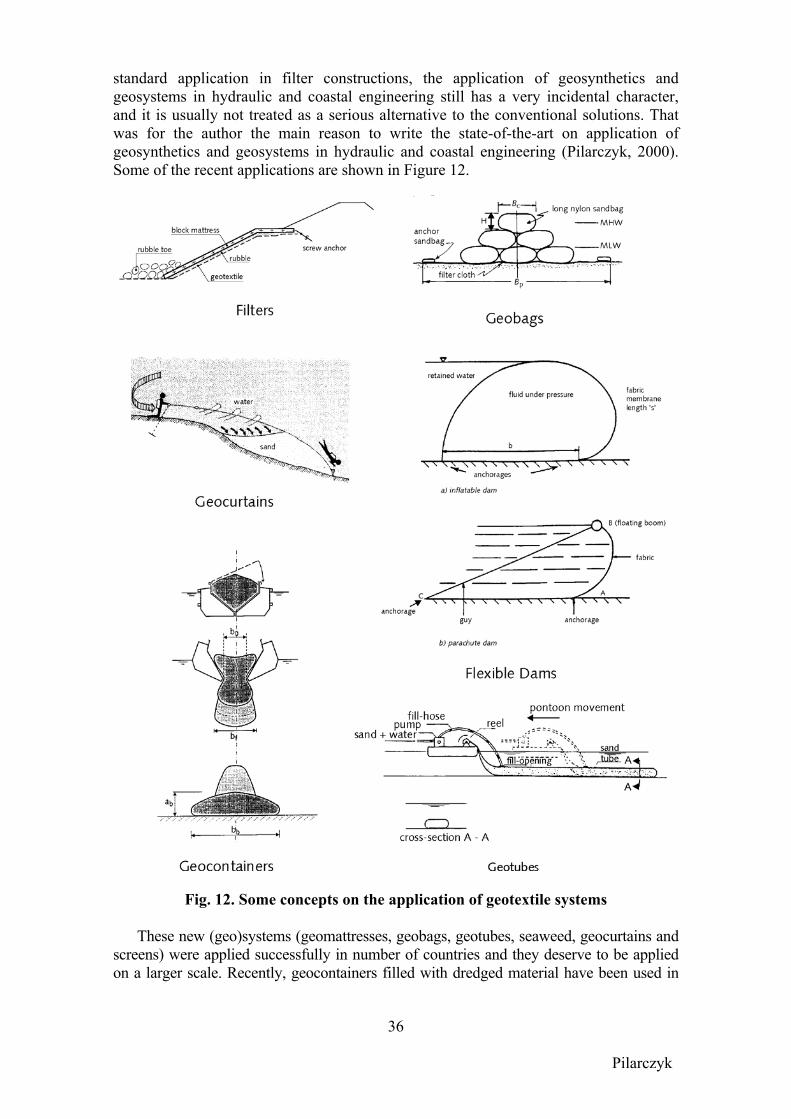
Pilarczyk
36
standard application in filter constructions, the application of geosynthetics and geosystems in hydraulic and coastal engineering still has a very incidental character, and it is usually not treated as a serious alternative to the conventional solutions. That was for the author the main reason to write the state-of-the-art on application of geosynthetics and geosystems in hydraulic and coastal engineering (Pilarczyk, 2000). Some of the recent applications are shown in Figure 12.
Fig. 12. Some concepts on the application of geotextile systems
These new (geo)systems (geomattresses, geobags, geotubes, seaweed, geocurtains and screens) were applied successfully in number of countries and they deserve to be applied on a larger scale. Recently, geocontainers filled with dredged material have been used in

Pilarczyk
37
dikes and breakwaters in a number of projects around the world, and their use in this field is growing very fast. Also, a number of new applications for geosynthetic curtains and screens have been developed and tested in practice.
Because of the lower price and easier execution these systems can be a good alternative for protective structures in hydraulic and coastal engineering both in developed and developing countries. The main obstacle in their application, however, is the lack of proper design criteria (in comparison with rock, concrete units, etc.). In the past, the design of these systems was mostly based on rather vague experience than on the general valid calculation methods. More research, especially concerning the large-scale tests and the evaluation of the performance of projects already realised, is still needed. In Pilarczyk (2000) an overview is given of the existing geotextile systems, their design methods (if available), and their applications. Where possible, some comparison with traditional materials and/or systems is presented. The recent research on some of these systems has provided better insight into the design and applications. TECHNOLOGY TRANSFER AND CAPACITY BUILDING
Know-how/technology transfer is an important expedient in the sustainable development of nations. Technology transfer is sustainable when it is able to deliver an appropriate level of benefits for an extended period of time, after major financial, managerial and technical assistance from an external partner is terminated. Apart from clearly identified objectives for Technology Transfer projects, proper project design and well-managed project execution, essential factors conditioning the survival of projects include: policy environment in recipient institution/country, appropriateness of technology and management organisational capacity (Overbeek et al, 1991).
Technology Transfer means the transfer of knowledge and skills, possibly in
combination with available tools, to institutions and individuals, with the ultimate aim to contribute to the sustainable development of the receiving institution (national) or country (international). Professional educational institutes are likely to restrict their work to specialised education and training of individuals. Institutions, however, generally aim at a broader approach. The objective of Technology Transfer should be to reinforce the capability of institutions and individuals to solve their problems independently. The required support can be indicated in a diagram differentiating between the analysis and solution phases of engineering problems. Obviously, knowledge and experience is required on three levels to obtain optimum results:
- knowledge of the processes - knowledge and experience in the use of process simulation techniques - experience in practical applications
Knowledge and experience can best be transferred in phases during a project that runs over several years. In many cases, however, budget restrictions call for another approach. The advisor may be called upon as a consultant, and the project includes only some of the phases mentioned above. Not only knowledge and skills must be transferred to the client’s staff, but it must also be integrated in the client’s organization for future, independent use. In order to guarantee an efficient interaction between the transfer and the integration activities, distinction in phases is required. One may distinguish the following realization phases:
Pilarczyk
38
1. professional education (general scientific/technological level) 2. professional training (new/specific technology/skills/tools) 3. development phase (physical/logistic adjustments at recipient party) 4. institute support (advisory services/exchange visits during project) The necessary number of phases may vary depending of situation (country, type of project).
Capacity building is important pre-condition for the realization of future challenges and transfer of know-how, especially for developing countries.
Hydraulic and Coastal engineering is a complex art. At this moment a limited number of phenomena can be understood with the help of the laws of physics and fluid mechanics. For the remainder, formulas have been developed with a limited accuracy. In addition, input data are limited availability and form another source of uncertainty. Consequently, a sound engineering approach is required, based on practical experience and supported by physical and numerical models, to increase the understanding of many phenomena and to come up with sustainable solutions. Especially, standard’ solutions do not exist in coastal engineering; solutions very much depend on the local circumstances as well as the social and political approach towards coastal engineering. Consequently, the transfer of coastal engineering knowledge is a complex art as well.
Sustainable transfer of hydraulic and coastal engineering technology at post-graduate level should therefore aim at increasing the capacities and skills of the engineers such that they are able to analyse a problem correctly and identify possible directions of solutions. Simply learning formulas and learning standard solutions for standard problems are not fruitful and even dangerous: such training does not increase the engineer’s understanding of the underlying processes and serious failures may be the result. Transfer of hydraulic and coastal engineering technology should therefore be problem oriented, practical in nature and geared towards the specific needs of the engineers following the training programme (Verhagen, 1999).
A general trend can be observed from applying rules to more conceptual thinking. Rules will change fast, so it is more important for an engineer to know the design philosophy. Also engineers have to learn where to find the most up-to-date knowledge regarding the design, which he is making at a certain moment. Because the increased growth in science, rules are outdated faster than in the past; this means that in most cases engineers should not apply the rules they have learned in university. So they should be trained always first to verify if the design method they learned in university is still valid. Engineers should be trained in a flexible application of the design methodologies they have learned. For design purposes the use of complicated computer software is increasing. The packages become more and more user friendly, but the insight in the computational process becomes less. This means that the direct link between output and input is less obvious. Engineers have to become more and more aware of the need of checking the output of these programs in inconsistencies (rather than on numerical accuracy). Because of the high quality of presentation methods of modern software, input inconsistencies are often not recognized in time. Engineers have to be trained to become more and more keen on this problem (Verhagen, 1996).
Pilarczyk
39
Transfer of technology to developing countries can also be a complex matter and
needs properly educated engineers. Copying solutions from the western, industrial countries for application in developing countries is in general not the best solution for solving the problems of developing countries. The main reason for that is that the available resources in the developing world are different from the resources in western countries. In the industrialized countries there is a strong tendency to solve problems in such a way that the amount of required labor decreases, so a capital-intensive solution is searched for. The reason for this is the very costly social system and the high standard of living. This causes a big difference between the hourly income and the hourly costs of labor. In developing countries this difference is much less, but on the contrary it is difficult and expensive to import industrial products from elsewhere. Also it is difficult to have sufficient capital available. For those countries it is more economic to search for solutions, which require hardly any investments, but are relatively labor intensive. These solutions generally require often more maintenance. However, increased maintenance costs are sometimes very pleasant, provided the initial investment is very low. The cost of the solution can be spread over a longer period without borrowing money for a capital-intensive solution. Maintenance is very important for sustainability of the investment/projects. Maintenance has to be done on the right moment. Also, there has to be a maintaining agency and there has to be a maintenance plan.
In solving these problems, one should always analyse the cause of the problem. Sometimes it is easier to change something in the estuary or river, than to combat the erosion. When it is not possible to take away the cause of the problem, then a number of technical tools are available as discussed in this book. In the design of these methods in most cases a low-investment approach can be followed. Low investment solutions generally require more maintenance than capital-intensive solutions. Therefore the construction has to be designed in such a way that maintenance can be performed easily, with local means, thus, with local materials, local people and with local equipment. These requirements are not very special and one can meet these requirements easily. The main problem is that one has to realise these points during the design phase.
We may conclude from the above that modern engineer must be educated in various technical and non-technical fields. The task of engineers involved in problems of developing countries should be the adaptation (translation) the actual knowledge to appropriate technologies suitable for their problems and their possibilities. CONCLUSIONS
Problem identification and understanding is very important for a proper choice of solution to water (flood) management and coastal problems. Generally, it may be concluded that there are both physical as well as social aspects to every problem. As a consequence mere technical solutions often turn out to be mistake. Furthermore, the future use of coast in general should be tailored to fit within the system, whether it is a recreational coast, a wetland or an ecosystem. For sustainable management, land use planning is required which does take floodplains and coastal waters into account. Proper quality of environmental boundary conditions defines the quality of design. In many cases, especially in less developed countries this can be a main obstacle in design of hydraulic and/or coastal structures. Further developments in forecasting and transformation techniques should be stimulated.
Pilarczyk
40
There are a large number of hydraulic and coastal structures. For some of them, workable design criteria have been developed in recent years (rubble-mound breakwaters, riprap, block revetments, filter structures, etc.). However, many of these criteria/formulae are still not quite satisfactory, mainly because they are lacking physical background, what makes extrapolation beyond the present range of experience rather risky. To solve this problem, it will be necessary to continue physical model experiments (on scale and in prototype) to develop, validate and calibrate new theories. Moreover, there is still a large number of systems with not adequate design techniques, for example, groins, submerged/reef breakwaters, a number of revetment types (gabions, geomattresses), geosystems, open filter, prediction and measures against scouring, etc. However, opposite to the functional design, the structural design can always be solved by the existing means (design criteria if available or model investigation), assuming availability of funds. Functional design (especially for coastal problems) is one of the most important and most difficult stages in the design process. It defines the effectiveness of the measure (project) in solving specific problem. Unfortunately, there are still many coastal problems where the present functional design methods are rather doubtful, especially concerning shoreline erosion control measures (i.e. groins, sea walls). Also, adequate measures against lee-side erosion (flanking) deserve more attention.
Alternative (waste) materials and geosynthetics and geosystems constitute potential alternatives for more conventional materials and systems. They deserve to be applied on a larger scale. The geosynthetic durability and the long-term behaviour of geosystems belong to the category of overall uncertainties and create a serious obstacle in the wider application of geosynthetics and geosystems and, therefore, are still matters of concern.
The understanding of the coastal responses in respect to the sedimentary coast and its behaviour is at least qualitatively available. However, reliable quantification is still lacking which make functional design of shore erosion control structures very risky. Much mathematical and experimental work is still to be done. Because of scale effects, the experiments will have to be carried out in large facilities or may be verification is even only possible on the basis of prototype observations over a long period. This work is so complicated that international co-operation is almost a prerequisite to achieve success within a reasonable time and cost frame.
Research on hydraulic and coastal structures should benefit from more co-operations among researchers and the associated institutions. Publishing basic information and standardised data would be very useful and helpful in establishing a more general worldwide data bank available, for example, on a website. Systematic (international) monitoring of realised projects (including failure cases) and evaluation of the prototype and laboratory data may provide useful information for verification purposes and further improvement of design methods. It is also the role of the national and international organisations to identify this lack of information and to launch a multiclient studies for extended monitoring and testing programmes, to provide users with an independent assessment of the long-term performance of hydraulic and coastal structures, including alternative materials and systems (geosynthetics, geosystems, alternative/waste materials, etc.).
Pilarczyk
41
Inventory, evaluation and dissemination of existing knowledge and future needs, and creating a worldwide accessible data bank are urgent future needs and some actions in this direction should be undertaken by international organisations involved (PIANC, IAHR, UNESCO/WMO, US Coastal Council). It should be recommended to organise periodically (within time span of 5 to 10 years) state-of-the-art reports on various sub-items of hydraulic and coastal engineering, which should be prepared by international experts in a certain field. It can be organised by creating semi-permanent working groups on specific subject and their activities should be paid from a common international fund, which should be established by one of the international organization.
Adjustment of the present education system as a part of capacity building for solving future problems should be recognised as one of the new challenges in hydraulic and coastal engineering. It is also important for the proper technology transfer to developing countries and development and maintaining of appropriate technologies for local use. Moreover, solidarity must be found in sharing knowledge, costs and benefits with less developed countries which are not able to facilitate the future requirements of integrated coastal management by themselves (on its own) including possible effects of climate change. More attention should be paid to integration of technological innovation with institutional reforms, to rise of awareness to change human behaviour, to developing of appropriate technologies that are affordable by poorer countries, to promoting technologies that would fit into small land holdings (local communities), and to capacity building (education), which is needed to continue this process in sustainable way.
Finally, there is a continuous development in the field of hydraulic and coastal engineering, and there is always a certain time gap between new developments (products and design criteria) and publishing them in manuals or professional books. Therefore, it is recommended to follow the professional literature on this subject for updating the present knowledge and/or exchanging new ideas. REFERENCES Ahrens, J.P., 1975, Large Wave Tank Tests of Riprap Stability, C.E.R.C. Technical
Memorandum no. 51, May. Ahrens, J.P., and T. Bender, 1991, Evaluating the performance of seawalls,
Proc.Coastal Structures and Breakwaters, London; publ. by Thomas Telford, 1992. ASCE, 1995, Wave Forces on Inclined and Vertical Wall Structures, Task Committee on
Forces on Inclined and Vertical Wall Structures, ASCE, New York. Battjes, J.A. and Janssen, J.P.F.M., 1978, Energy loss and set-up due to breaking of
random waves, Proc. 16th Int. Conf. Coastal Engineering, ASCE, 569-587. Bezuijen, A. and Klein Breteler, M., 1966, Design Formulas for Block Revetments, J.
Waterway, Port, Coastal and Ocean Eng. 122, 6. Booij, N., Holthuijsen, L.H. and Ris, R.C., 1996, The “SWAN” wave model for shallow
water, Proc. 25th Int. Conf. Coastal Engineering, ASCE, Orlando. Borsboom, M., N. Doorn, J. Groeneweg and M. van Gent, 2000, A Boussinesq-type
wave model that conserves both mass and momentum, ASCE, Proc. ICCE, Sydney. Borsboom, M., N. Doorn, J. Groeneweg and M. van Gent, 2001, Near-shore wave
simulations with a Boussinesq-type model including breaking, Proc. Coastal Dynamics 2001, Lund.
Pilarczyk
42
Burger, A.M., M. Klein Breteler, L. Banach, A. Bezuijen and K.W. Pilarczyk, 1990; Analytical design formulas for relatively closed block revetments; Journal of Waterway, Port, Coastal and Ocean Eng., ASCE, vol. 116 no. 5, Sept/Oct.
Burcharth, H.F., 1980, Full-scale dynamic testing of Dolosse to destruction, Proc. 17thIntern. Conf. on Coastal Engineering, Sydney; also, Coastal Engineering, Elsevier, No. 4, 1981, pp. 229-251.
Burcharth, H.F., 1983, Materials, structural design of armour units, Proc. Seminar on rubble mound breakwaters, Royal Institute of Technology, Stockholm, Sweden; Bulletin No. TRITA-VBI-120 (Ed. Gosta Werner).
Burcharth, H.F., 1984, Fatigue in Breakwater Concrete Armour Units, Proc. 19th Intern.Conf. on Coastal Engineering, Houston, Texas.
Burcharth, H.F., 1987, The lessons from recent breakwater failures – Development in Breakwater Design, Proceedings World Federation of Engineering Organizations, Technical Congress on Inshore Engineering, may 1987, Vancouver, Canada.
Burcharth, H.F., 1991, Bosaso Harbour. A new hot-climate port development. Proc. 3rd Intern. Conf. on Coastal & Port Engng. in Developing Countries, Mombassa.
Burcharth, H.F., 1991, Design innovation, including recent research contributions, Proc.Coastal Structures and Breakwaters, Thomas Telford, London.
Burcharth, H.F., 1992, Design of rubble mound breakwaters. Structural Integrity. Proc.Short Course on Design Reliability of Coastal Structures, 23rd
Int. Conf. on Coastal Engineering, Venice, Italy.
Burcharth, H.F., 1994, Reliability evaluation of a structure at sea, Proc. Int. Workshop on Wave Barriers in Deepwaters, Port and harbour Research Institute, Yokosuka, Japan.
Burcharth, H.F., 1999a, State of the art in conceptual design of breakwaters, Proc. Coastal Structures’99, Vol. 1, A.A. Balkema, publisher, Rotterdam.
Burcharth, H.F., 1999b, The PIANC safety factor system for breakwaters, Proc. Coastal Structures’99, Vol. 2, A.A. Balkema, publisher, Rotterdam.
Burcharth, H.F, Liu, Z. and Troch, P., 1999c, Scaling of core material in rubble mound breakwater model tests, Proc. COPEDEC V, Cape town, South Africa.
Burcharth, H.F., 2001, Verification of overall safety factors in deterministic design of model tested breakwaters, Proc. Advanced design of maritime structures in 21st century, Port and Harbour Research Institute, Yokosuka, Japan.
Burcharth, H.F., d’Angremond, K., Van der Meer, J.W. and Liu, Z., 2000, Empirical formulae for breakage of Dolosse and Tetrapods, Coastal Engineering, Elsevier, 40.
CEN/CR ISO, 1998, Guide to durability of geotextiles and geotextiles related products, European Normalization Committee (CEN), CR ISO 13434, Paris.
CIRIA, 1986, Sea Wall; Survey of performance and design practice, Construction Industry Research and Information Association (CIRIA), Tech. note 125, London.
CIRIA, 1990, Guide on the uses of groynes in coastal engineering, Construction Industry Research and Information Association (CIRIA), report 119, London.
EAU 1996, 2000, Recommendations of the Committee for Waterfront Structures, Harbours and Waterways, 7th English edition, Ernst & Sohn, Berlin.
CIRIA, 1996, Beach management manual, CIRIA, London. CUR, 1995, Design manual for pitched slope protection, CUR report 155, ISBN 90
5410 606 9, Gouda, the Netherlands. CUR, 1997, Beach nourishments and shore parallel structures, CUR-report 97-2, NL. CUR/CIRIA, 1991, Manual on use of rock in coastal engineering, CUR/CIRIA report 154,
Centre for Civil Engineering Research and Codes (CUR), Gouda, the Netherlands.
Pilarczyk
43
CUR/RWS, 1995, Manual on the use of rock in hydraulic engineering, CUR report 169, Centre for Civil Engineering Research and Codes (CUR), P.O. Box 420, 2800 AK Gouda, A.A. Balkema (Publisher), NL.
CUR/TAW, 1990, Probabilistic Design of Flood Defences, CUR-report 141/TAW guide, Gouda, the Netherlands. Centre for Civil Engineering Research and Codes (CUR), Technical Advisory Committee on Water Defences (TAW),
D’Angremond, K. and Van Roode, F.C., 2001, Breakwaters and closure dams, Delft University Press, Delft, the Netherlands.
D’Angremond, K. 2001, Coastal Engineering, Achievements and Challenges, International Symposium on Marine Engineering, Singapore.
De Groot, M.B., Bezuijen, A., Burger, A.M. and Konter, J.L.M., 1988, The interaction between soil, water and bed or slope protection. Int. Symp. on Modelling Soil-Water-Structure Interactions, Delft, A. Balkema.
Fowler, R.E. and Allsop, N.W.H., 1999, Codes, standards and practice for coastal enginee-ring in the UK, Proc. Coastal Structures’99, Vol. 2, A.A. Balkema, Rotterdam.
Giroud, J.P., 1987, Geotextiles and Related Products, in Geotechnical Modelling and Applications, Sayed M. Sayed editor, Gulf Publishing Company, Houston.
Goda, Y., 1985, Random Seas and Design of Maritime Structures, Univ. of Tokyo Press. Hanson, H., Thevenot, M.M. and Kraus, N.C., 1996, Numerical simulation of shoreline
change with longshore sand waves at groins, Proc. Coastal Engineering, Orlando. Henneveld, R.J.P. and Van der Zwan, J.Th., 1997, Sustainable Development and Road
Construction; Sustainable Building in The Netherlands, 13th World Meeting IRF, Toronto, Canada.
Hibberd, S. and D.H. Peregrine, 1979, Surf and run-up on a beach: a uniform bore, J. of Fluid Mechanics, Vol.95, part 2, pp.323-345.
Hillen, R. and Jorissen, R.E., 1995, Major Floods Events in the Netherlands, 30th Conf.Of River &Coastal Engineers, MAFF, London.
Hsu, J.R.C., Uda, T. and Silvester, R., 1999, Shoreline Protection Methods - Japanese Experience, in Handbook of Coastal Engineering (J.B. Herbich, ed.), McGraw-Hill.
Itoh, K, Toue, T. and Katsui, H., 2001, Numerical simulation of submerged breakwater deformation by DEM and VOF, Proc. Advanced design of maritime structures in 21st century, Port and Harbour Research Institute, Yokosuka, Japan.
Jorissen, R.E. and Stallen, P.J.M., 1998, Quantified Societal risk and Policy Making, Kluwer Academic Publishers, Boston/Dordrecht/London.
Jorissen, R., Litjens-van Loon, J. and Mendez Lorenzo, A., 2001, Flooding risk in coastal areas; risk, safety levels and probabilistic techniques in five countries along the North Sea coast, Rijkswaterstaat, Road and Hydraulic Engineering Division, Delft, the Netherlands.
Klein Breteler, M. and A. Bezuijen, 1988, The permeability of closely placed blocks on gravel, SOWAS’88, A.A. Balkema.
Klein Breteler, M., T. Stoutjesdijk, and K. Pilarczyk, 1998, Design of alternative revetments, 26th ICCE, Copenhagen.
Kennedy, A.B., Q. Chen, J.T. Kirby and R.A. Dalrymple (2000), Boussinesq modelling of wave transformation, breaking and runup. I One Dimension, J. of Waterway, Port, Coastal and Ocean Engrg, ASCE, Vol.126, pp.39-47.
Kobayashi, N., A.K. Otta and I. Roy, 1987, Wave reflection and run-up on rough slopes, J. of Waterway, Port, Coastal and Ocean Engrg, ASCE, Vol.113, No.3.
Kobayashi, N., 1999, Future of coastal engineering and structures, Proceedings of Coastal Structures’99, A.A. Balkema, Rotterdam.
Pilarczyk
44
Koch, M., 2000, Natural hazards and disasters: origins, risks, mitigation and prediction, Int. Symposium on River Flood Defence, Kassel, Germany.
Köhler, H.J. Bezuijen A., 1995 Permeability influence of filter layers on the stability of rip-rap revetments under wave attack. Proc. 5th Int. Conf. Geotextiles, Geomembranes and Related Products, Singapore.
Kraus, N.C. and O.H. Pilkey, eds., 1988. The effect of seawalls on the beach, Journal of Coastal Research, Special issue no. 4.
Larson, M., Kraus, N.C. and Hanson, H., 1997, Analytical Solutions of the One-Line Model of Shoreline Change Near Coastal Structures, J. Waterway, Port, Coastal and Ocean Engr., ASCE.
Losada, I.J., ed., 2000, Coastal Structures’99, Proceedings of the International Conference Coastal Structures’99, Santander, Spain, A.A. Balkema, publisher, Rotterdam/Brookfield ([email protected]).
MAFF, 1997, interim guidance for the strategic planning and appraisal of flood and coastal defence schemes, Ministry of Agriculture, Fisheries and Flood, London.
MAFF, 2000, Flood and Coastal Defence Project Appraisal Guidance; Approaches to Risk, Ministry of Agriculture, Fisheries and Flood, London.
Mannsbart, G. and B.R. Christopher, 1997, Long-term performance of nonwoven geotextile filters in five coastal and bank protection projects, Geotextiles and Geomembranes, Vol. 15, no. 4-6.
Meadowcroft, I.C., Reeve, D.E., Allsop, N.W.H., Diment, R.P. and J. Cross, 1995,Development of new risk assessment procedures for coastal structures, Proc. Advances in coastal structures and breakwaters, Thomas Telford, 1996, London.
NRC, 1995, Beach nourishment and protection, National Research Council, Washington, D.C., National Academy Press.
NRC, 1999, Meeting research and education needs in coastal engineering, National Research Council, Washington, D.C., National Academy Press.
OCADI, 1999/2002, The Technical Standards and Commentaries for Port and Harbour Facilities in Japan, The Overseas Coastal Area Development Institute of Japan, (revised English version), Tokyo.
Oumeraci, H., Allsop, N.W.H., De Groot, M.B., Crouch, R.S., and Vrijling, J.K., 1999, Probabilistic design methods for vertical breakwaters (PROVERBS), Proceedings of Coastal Structures’99, A.A. Balkema, Rotterdam.
Oumeraci, H., 2001, Conceptual framework for risk-based design of coastal flood defences; a suggestion, Proc. Advanced design of maritime structures in 21st century, Port and Harbour Research Institute, Yokosuka, Japan.
Overbeek, H.J, J.van der Weide and H. Derks, 1991, Effective Technology Transfer from One Institute to Another, Delft Hydraulics (for IAHR).
Partensky, H.W., 1998, The European research programmes in coastal engineering, Proc. 26th Coast. Eng. Conf., Denmark.
PHRI, 2001, Advanced Design of Maritime Structures in 21st Century, Port and Harbour Research Institute, Yokosuka, Japan.
PIANC, 1987, Guidelines for the design and construction of flexible revetments incorporating geotextiles for inland waterways, PIANC, Supplement to Bulletin No. 57, Brussels, Belgium.
PIANC, 1992, Guidelines for the design and construction of flexible revetments incorporating geotextiles in marine environment, PIANC, Supplement to Bulletin No. 78/79, Brussels, Belgium.
Pilarczyk
45
PIANC, 1992, Analysis of rubble mound breakwaters, Report of Working Group 12, PIANC, Supplement to Bulletin No. 78/79, Brussels, Belgium.
Pilarczyk, K.W., 1984, (a) Stability of rock-fill structures, (b) Filters, in Closure Tidal Basins, Huis in ‘t Veld et al. Editors), Delft University Press, the Netherlands.
Pilarczyk, K.W., ed., 1990, Coastal Protection, A.A. Balkema Publisher, Rotterdam, Netherlands ([email protected]).
Pilarczyk, K.W., ed., 1998, Dikes and Revetments, A.A. Balkema Publisher, NL. Pilarczyk, K.W., 1999, Design of Dikes and Revetments – Dutch Practice, in Handbook
of Coastal Engineering (J.B. Herbich, ed.), McGraw-Hill. Pilarczyk, K.W., 2000, Geosynthetics and Geosystems in Hydraulic and Coastal
Engineering, A.A. Balkema, Rotterdam. Pilarczyk, K.W., 2001, Unification of stability formulas for revetments, Proc. IAHR
Congress, Beijing, China. Pilarczyk, K.W. and K. den Boer, 1983, Stability and profile development of coarse
materials and their application in coastal engineering, Proc. Inter. Conference on Coastal and Port Engineering in Developing Countries, Colombo, Sri Lanka (also Delft Hydraulics, publication no. 293).
Pilarczyk, K.W., Laan, G.J. and Den Adel, H., 1987, Application of some waste materials in hydraulic engineering, 2nd European Conference on Environmental Technology, Amsterdam.
Pilarczyk, K.W. and Zeidler, R., 1995, Offshore breakwaters and shore evolution control, A.A. Balkema Publisher, Rotterdam, Netherlands.
Pilarczyk, K.W., Klein Breteler, M. and Bezuijen, A., 1995, Wave Forces and Structural Response of Placed Block Revetments on Inclined Structures, in Wave Forces on Inclined and Vertical Wall Structures, ASCE, New York.
Pilarczyk, K.W. and Nguyen Sy Nuoi, 2002, Flood protection and management in Vietnam, Coastal Disasters’02, San Diego.
Przedwojski, B., Blazejewski, R. and K.W. Pilarczyk, 1995, RIVER TRAINING TECHNIQUES; Fundamentals, Design and Applications, A.A. Balkema Publisher, Rotterdam.
RIKZ, 2001, Coastal protection Guidelines; a guide to copy with erosion in the broader perspective of Integrated Coastal Zone Management, CZM-C 2001.03, National Institute for Coastal and Marine Management (RIKZ), The Hague, The Netherlands.
Ris, R.C., 1997, Spectral modelling of wind waves in coastal areas, Ph.D.-thesis, Delft University of Technology, ISBN 90-407-1455-X, Delft University Press, Delft.
Ris, R.C., N. Booij, L.H. Holthuijsen, R. Padilla-Hernandez, IJ.G.Haagsma, 1998, Swan Cycle 2; User manual for version 30.75, Delft University of Technology.
ROM 02.99, 1999, Acciones en el Proyecto de Obras Maritimas y Portuarias. Puertos del Estado. Revision for the Technical Committee. (Puertos del Estada, Avda. Del Pon 10, Madrid 28042, Spain)
Samuels, P.G., 2000, An overview of flood estimation and flood prevention, Int. Symposium on River Flood Defence, Kassel, Germany.
RWS, 1994. DESIGN PLAN OOSTERSCHELDE STORM-SURGE BARRIER: Overall Design and Design Philosophy, Ministry of Transport, Public Works and Water Management, Rijkswaterstaat (RWS), (A.A. Balkema, Publ.), Netherlands.
RWS (Rijkswaterstaat), 1987. The Closure of Tidal Basins; closing of estuaries, tidal inlets and dike breaches, published by the Delft University Press, Delft, NL.
RWS (Rijkswaterstaat), 1990. A new coastal defence policy for The Netherlands, Rijkswaterstaat (RWS), Tidal Water Division, The Hague.
Pilarczyk
46
Schäffer, H.A., R. Deigaard and P. Madsen, 1992, A two-dimensional surf-zone model based on the Boussinesq equations, ASCE, Proc. ICCE’92, Vol.1, Venice.
Schiereck, G.J., 2001, Introduction to bed, bank and shore protection, Delft University Press, Delft.
SPM, 1984, Shore Protection Manual, Coastal Engineering Research Centre, US Corps of Engineers, 4th edition, Washington.
Troch, P., 2001, Experimental study an numerical modelling of pore pressure attenuation inside a rubble mound breakwater, PIANC Bulletin No. 108, Brussels.
TAW, 1996, Guidelines on Safety Assessment for Water Retaining Structures, Technical Advisory Committee on Water Defences (TAW), Road and Hydraulic Engineering Division, Delft, the Netherlands.
TAW, 1999, Guide for the Design of Sea- and Lake dikes, Technical Advisory Committee on Water Defences (TAW), Road and Hydraulic Engineering Division, Delft, the Netherlands.
TAW, 2000, Fundamentals on water defences, Technical Advisory Committee on Water Defences (TAW), Road and Hydraulic Engineering Division, Delft, the Netherlands.
Van der Meer, J.P., 1988, Rock slopes and gravel beaches under wave attack, PhD-thesis Delft University of Technology, April 1988; (also available as Delft Hydraulics Communication 396).
Van der Weide, J., 1989, General introduction and hydraulic aspects, in Short Course on design of coastal structures, Asian Institute of Technology, Bangkok.
Van Gent, M.R.A., 1994, The modelling of wave action on and in coastal structures, Coastal Engineering, Vol.22 (3-4), pp.311-339, Elsevier, Amsterdam.
Van Gent, M.R.A., 1995, Wave interaction with permeable coastal structures, Ph.D.-thesis, Delft University of Technology, ISBN 90-407-1182-8, Delft University Press.
Van Gent, M.R.A., 1999, Physical model investigations on coastal structures with shallow foreshores; 2D model test on the Petten Sea-defence, Delft Hydraulics Report H3129-July 1999, Delft.
Van Gent, M.R.A., 2000, Wave run-up on dikes with shallow foreshores, ASCE, Proc. ICCE 2000, Sydney.
Van Gent, M.R.A. and N. Doorn, 2000, Numerical model investigations on coastal structures with shallow foreshores; Validation of numerical models based on physical model tests on the Petten Sea-defence, Delft Hydraulics Report H3351.
Van Gent, M. and Doorn, N, 2001, Numerical model simulations of wave propagation and run-up on dikes with shallow foreshores, Coastal Dynamics’01.
Van Hijum, E. and Pilarczyk, K.W., 1982, Gravel beaches; equilibrium profile and longshore transport of coarse material under regular and irregular wave attack, Delft Hydraulics Laboratory, Publication no. 274, July, Delft, the Netherlands.
Verhagen, H.J. and Yap, J.T.L., 1992, Coastal Zone Management with relation to low investment solutions, 2nd Seminar of PIANC for Developing Countries, Surabaya.
Verhagen, H.J., 1996, Education of coastal engineers for the 50th ICCE, Proc. ICCE ’96, Orlando.
Verhagen, H.J. and De Vries, W.S., 1999, Sustainable transfer of coastal engineering knowledge at post gradual level, Proc. COPEDEC’99, Cape Town.
Vrijling, J.K., van Hengel, W. and Houben, R.J., 1998, Acceptable risk as a basis for design, Journal Rel. Enging. and System Safety 59.
Key Words: hydraulic and coastal structures, applications, methodology, design codes,
manuals, developments, review, international perspective
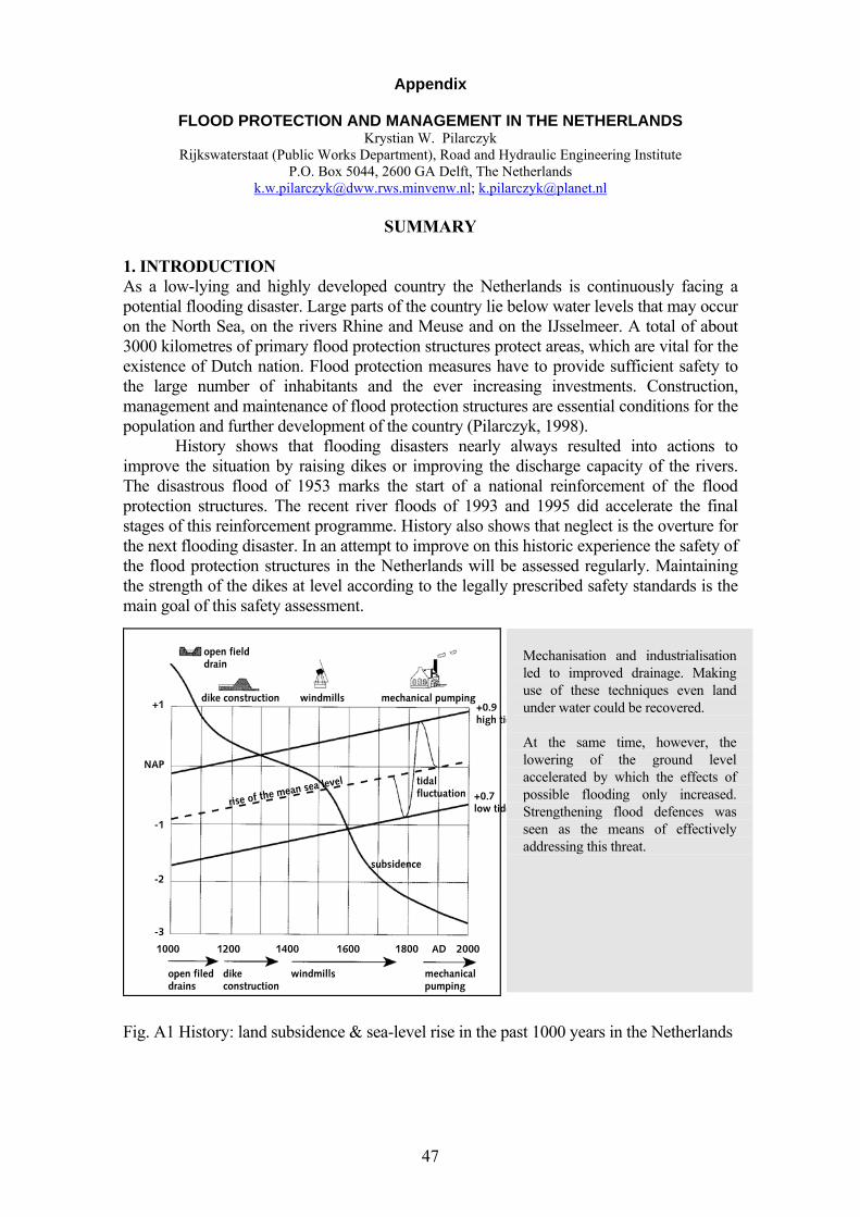
47
Appendix
FLOOD PROTECTION AND MANAGEMENT IN THE NETHERLANDS Krystian W. Pilarczyk
Rijkswaterstaat (Public Works Department), Road and Hydraulic Engineering Institute P.O. Box 5044, 2600 GA Delft, The Netherlands
[email protected]; [email protected]
SUMMARY 1. INTRODUCTION As a low-lying and highly developed country the Netherlands is continuously facing a potential flooding disaster. Large parts of the country lie below water levels that may occur on the North Sea, on the rivers Rhine and Meuse and on the IJsselmeer. A total of about 3000 kilometres of primary flood protection structures protect areas, which are vital for the existence of Dutch nation. Flood protection measures have to provide sufficient safety to the large number of inhabitants and the ever increasing investments. Construction, management and maintenance of flood protection structures are essential conditions for the population and further development of the country (Pilarczyk, 1998). History shows that flooding disasters nearly always resulted into actions to improve the situation by raising dikes or improving the discharge capacity of the rivers. The disastrous flood of 1953 marks the start of a national reinforcement of the flood protection structures. The recent river floods of 1993 and 1995 did accelerate the final stages of this reinforcement programme. History also shows that neglect is the overture for the next flooding disaster. In an attempt to improve on this historic experience the safety of the flood protection structures in the Netherlands will be assessed regularly. Maintaining the strength of the dikes at level according to the legally prescribed safety standards is the main goal of this safety assessment.
Fig. A1 History: land subsidence & sea-level rise in the past 1000 years in the Netherlands
Mechanisation and industrialisation led to improved drainage. Making use of these techniques even land under water could be recovered. At the same time, however, the lowering of the ground level accelerated by which the effects of possible flooding only increased. Strengthening flood defences was seen as the means of effectively addressing this threat.
48
In the recent years the practical knowledge and experience with respect to design and management of water defences was gathered in The Netherlands and elsewhere. It has resulted in preparing a set of design guidelines for design and maintenance of dikes, seawalls, revetments and other water defence structures. 2. BASIC PRINCIPLES OF FLOOD PROTECTION Flooding is one of the main causes of the loss of life, loss of property and income in many parts of the world. Thus a lack of investment in or neglected maintenance of flood defences may jeopardise the entire effort to improve the lot of the people living along rivers or bordering the sea. Consequently the aid to develop an adequate system of protection against floods should be part of the development policy. It should be realised that flood protection consists of two tasks: Designing, building and upholding a flood management system. Designing, constructing and maintaining a flood defence system
With flood management system we indicate the organisational system necessary to let river discharges up to a certain size (return period) pass through the flood defence system with limited consequences. In case of a discharge that exceeds the capacity of the flood defence system the management system should aim to limit the consequences as far as possible. With flood defence system we indicate the physical system necessary to let river discharges up to a certain size (return period) pass the area under study with limited consequences. When designing a flood defence system all options mentioned above have to be carefully studied. History shows however that the smaller scale improvements are easier to implement than the measures on catchments scale. The reasons are economical as well as political.
A further assessment is that the interaction of five more or less independent sub-systems is necessary for a fruitful and effective joint-functioning of the flood defence and flood management systems. 1. The natural system that encompasses all natural phenomena in the catchment 2. The infrastructure of dikes, dams, reservoirs, green rivers or bypasses, etc. as laid
out by man 3. The system to observe phenomena and to communicate the results 4. The professional system consisting of people educated to understand the behaviour
of the natural and the trained water system. 5. The system of users and beneficiaries of the entire set up, that in the end bears the
costs of it’s installation and maintenance. These people will influence the course of the interventions directly or indirectly via their political representatives.
All five systems must interact in a smooth effective way. If the contribution of one is omitted or neglected improvements or changes in the flood defence and flood management systems will prove to be elusive at least and perhaps unattainable. The history of the improvement of the river system in the Netherlands shows clearly how difficult it is to introduce changes if one or more systems are excluded or non-existent. Organisational and Legal aspects in the Netherlands The Netherlands is a decentralized state. National, regional and local authorities operate both together and independently. The Netherlands is protected against flooding by nearly 3000 kilometres of primary flood defences, of which only 300 kilometres is
49
managed by the regional directorates of the Ministry. The other defences are managed by Water Boards. Water Boards is a form a specific democracy on a local level. Their tasks are limited to water management (quantity, quality, flood protection) only and they are only allowed to raise taxes for these purposes. Already in the 12th century there were water boards in The Netherlands (no national, regional or other , local authority did exist at that time). Again the inhabitants elect their representatives (according to their degree of interest), which in their turn elect the ‘heemraden’. The dike reeve is chairing the board of ‘heemraden’ and is appointed by the Minister of Internal Affairs.
The scope of management and maintenance of this infrastructure is aimed at the main themes: safety, transport and ecology. The national water management plan is a reference for regional authorities involved in water management. Although this contribution focuses on the national infrastructure, regional infrastructure and water systems are just as vital as their national pendants. The role of provinces, water boards and local communities is essential to reach policy goals. These authorities make their own management plans based upon the national management plan.
The Dutch have a tradition of dealing with water. But dewatering low-lying areas for agriculture however has serious negative effects due to the settlement of soil (due to lowering of the groundwater table). The effect of (increased) sea level rise has to be added to this. It has become clear to us that we need a more adaptive strategy to accommodate the rising waters instead of to combat this threat. The main policy goal is therefore : To have and to hold a safe and habitable country and to maintain and develop resilient water systems, which allow a sustainable use.
Integral water management is our key to accomplish this audacious goal. By managing the water system (water, bottom and banks) as a whole based on assigned functions the Ministry of Transport, Public Works and Water Management focuses on realising reference situations in the national water systems. With regional and international partners agreements are made to reach a similar approach for entire catchment areas. The national management plan describes main functions and management goals for each policy goals. Flood protection and transport are the so-called high priority functions. Maintaining safety of primary flood defences is one of these policy goals. All primary flood defence must meet the legally prescribed safety standard. The following Safety Standards were approved for The Netherlands:
- North and South Holland/Amsterdam, The Hague, Rotterdam/: 1/10000 per year; - Other coastal areas (with lower economic value): 1/4000 per year; - Lower river reaches (with partial influence of tide and storm surges): 1/2000 p.y.; - Middle and upper river reaches: 1/1250 per year.
The actual probabilistic approach aims to give protection when the risks are felt to be high. Risk is defined as the probability of a disaster i.e. a flood related to the consequences: Risk = Probability x Consequences In 1996 a Flood Protection Act (FPA) was approved by Dutch Parliament. The purpose of this Act is to provide and to maintain long-term safety for The Netherlands. It defines that each 5 years a National Safety Assessment of the actual state of safety of
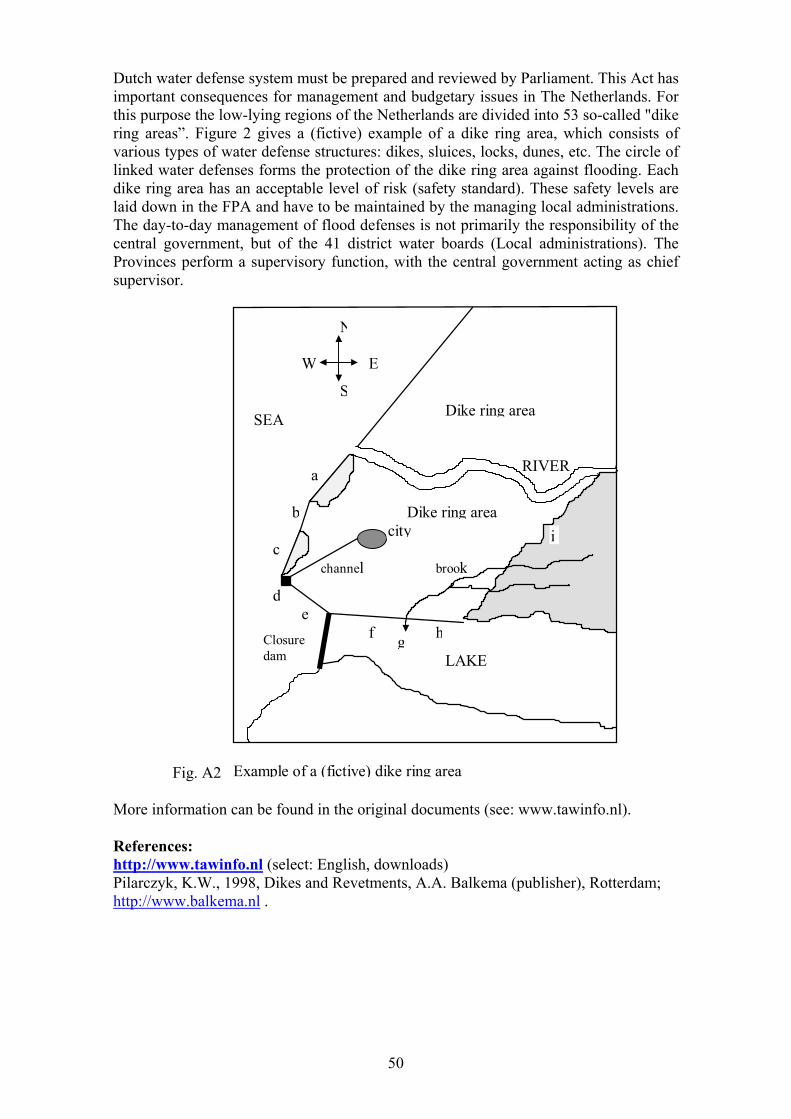
50
Dutch water defense system must be prepared and reviewed by Parliament. This Act has important consequences for management and budgetary issues in The Netherlands. For this purpose the low-lying regions of the Netherlands are divided into 53 so-called "dike ring areas”. Figure 2 gives a (fictive) example of a dike ring area, which consists of various types of water defense structures: dikes, sluices, locks, dunes, etc. The circle of linked water defenses forms the protection of the dike ring area against flooding. Each dike ring area has an acceptable level of risk (safety standard). These safety levels are laid down in the FPA and have to be maintained by the managing local administrations. The day-to-day management of flood defenses is not primarily the responsibility of the central government, but of the 41 district water boards (Local administrations). The Provinces perform a supervisory function, with the central government acting as chief supervisor.
Fig. A2 Example of a (fictive) dike ring area
channel
LAKE
SEA
RIVER
city
a
b
c
de
Closure dam
f g h
brook
Dike ring area
Dike ring area
N
E
S
W
i
More information can be found in the original documents (see: www.tawinfo.nl). References: http://www.tawinfo.nl (select: English, downloads) Pilarczyk, K.W., 1998, Dikes and Revetments, A.A. Balkema (publisher), Rotterdam; http://www.balkema.nl .


![[Pilarczyk] Adrenaline programing implementing - SOA and BPM in your application](https://img.pdfslide.net/doc/110x75/55923e1b1a28ab103f8b458b/pilarczyk-adrenaline-programing-implementing-soa-and-bpm-in-your-application.jpg)