Embed Size (px)
Citation preview
Form MHD56114
PARTS, OPERATION AND MAINTENANCE MANUAL
THIRD GENERATION
MODEL FA2.5A
(Dwg. MHP2415)
READ THIS MANUAL BEFORE USING THESE PRODUCTS. This manualcontains important safety, installation, operation and maintenanceinformation. Make this manual available to all persons responsible for theinstallation, operation and maintenance of these products.
WARNINGDo not use this winch for lifting, supporting, or transporting people or lifting orsupporting loads over people.
Always operate, inspect and maintain this winch in accordance with American Society ofMechanical Engineers (ASME B30.7) and any other applicable safety codes andregulations.
Form MHD56114Edition 4February 200371299358© 2003 Ingersoll-Rand Company
2 MHD56114 - Edition 4
CONTENTS
Description Page No.
Safety InformationDanger, Warning, Caution and Notice .................................................................................................................................................................3Safety Summary...................................................................................................................................................................................................3Safe Operating Instructions .................................................................................................................................................................................4Warning Labels and Tag ......................................................................................................................................................................................5
SpecificationsDescription...........................................................................................................................................................................................................8Traceability ..........................................................................................................................................................................................................8
InstallationMounting..............................................................................................................................................................................................................9Wire Rope ..........................................................................................................................................................................................................10Air Supply..........................................................................................................................................................................................................12Motor .................................................................................................................................................................................................................13Emergency Stop and Overload System..............................................................................................................................................................13Initial Winch Operating Checks.........................................................................................................................................................................13
OperationWinch Controls ..................................................................................................................................................................................................14Winch Brakes.....................................................................................................................................................................................................17Constant Tension Manifold (Optional Feature) .................................................................................................................................................17Free Spool (Optional Feature) ...........................................................................................................................................................................18
InspectionRecords and Reports ..........................................................................................................................................................................................19Frequent Inspection............................................................................................................................................................................................19Periodic Inspection ............................................................................................................................................................................................20Winches Not In Regular Use .............................................................................................................................................................................20Inspection and Maintenance Report ..................................................................................................................................................................21
Troubleshooting................................................................................................................................................................................................22
LubricationGeneral Lubrication ...........................................................................................................................................................................................23Wire Rope ..........................................................................................................................................................................................................24
MaintenanceAdjustments .......................................................................................................................................................................................................25Disassembly .......................................................................................................................................................................................................26Cleaning, Inspection and Repair ........................................................................................................................................................................30Assembly ...........................................................................................................................................................................................................30Testing................................................................................................................................................................................................................36
Parts SectionWinch Cross Section Drawing ..........................................................................................................................................................................38Winch Parts Drawings and Parts Lists Table of Contents ...............................................................................................................................39Winch Parts Drawings and Parts Lists........................................................................................................................................................40 - 67
Parts Ordering Information ..........................................................................................................................................................................68
Warranty ..........................................................................................................................................................................................................71
Office Locations ..............................................................................................................................................................................................72
MHD56114 - Edition 4 3
SAFETY INFORMATION
This manual provides important information for all personnel involved with the safe installation, operation and proper maintenance of this product. Even if you feel you are familiar with this or similar equipment, you should read this manual before operating the winch.
Danger, Warning, Caution and Notice
Throughout this manual there are steps and procedures which, if not followed, may result in a hazard. The following signal words
Danger is used to indicate the presence of a hazard which will cause severe injury or death if the warning is ignored.
Warning is used to indicate the presence of a hazard which can cause severe injury or death if the warning is ignored.
Caution is used to indicate the presence of a hazard which will or can cause injury or property damage if the warning is ignored.
Notice is used to notify people of installation, operation, or maintenance information which is important but not hazard-related.
DANGER
WWAARRNNIINNGG
CCAAUUTTIIOONN
NNOOTTIICCEE
are used to identify the level of potential hazard.
Safety Summary
WARNING• Do not use this winch for lifting, supporting, or transporting people or lifting or supporting loads over people.• The supporting structures and load-attaching devices used in conjunction with this winch must provide an adequate safety factor to handle the rated load, plus the weight of the winch and attached equipment. This is the customer’s responsibility. If in doubt, consult a registered structural engineer.
Ingersoll-Rand winches are manufactured in accordance with the latest ASME B30.7 standards.
The National Safety Council, Accident Prevention Manual for Industrial Operations, Eighth Edition and other recognized safety sources make a common point: Employees who work near suspended loads or assist in hooking on or arranging a load should be instructed to keep out from under the load. From a safety standpoint, one factor is paramount: conduct all lifting or pulling operations in such a manner that if there were an equipment failure, no personnel would be injured. This means keep out from under a raised load and keep out of the intended path of any load.
The Occupational Safety and Health Act of 1970 generally places the burden of compliance with the user, not the manufacturer. Many OSHA requirements are not concerned or connected with the manufactured product but are, rather, associated with the final installation. It is the owner’s and user’s responsibility to determine the suitability of a product for any particular use. It is recommended that all applicable industry, trade association, federal, state and local regulations be checked. Read all operating instructions and warnings before operation.
Rigging: It is the responsibility of the operator to exercise caution, use common sense and be familiar with proper rigging techniques. Refer to ASME B30.9 for rigging information, American Society of Mechanical Engineers, Three Park Avenue, New York, NY 10016.
This manual has been produced by Ingersoll-Rand to provide dealers, mechanics, operators and company personnel with the information required to install, operate, maintain and repair the products described herein.
It is extremely important that mechanics and operators be familiar with the servicing procedures of these products, or like or similar products, and are physically capable of conducting the procedures. These personnel shall have a general working knowledge that includes:1. Proper and safe use and application of mechanics common
hand tools as well as special Ingersoll-Rand or recommended tools.
2. Safety procedures, precautions and work habits established by accepted industry standards.
Ingersoll-Rand cannot know of, or provide all the procedures by which product operations or repairs may be conducted and the hazards and/or results of each method. If operation or maintenance procedures not specifically recommended by the manufacturer are conducted, it must be ensured that product safety is not endangered by the actions taken. If unsure of an operation or maintenance procedure or step, personnel should place the product in a safe condition and contact supervisors and/or the factory for technical assistance.
4 MHD56114 - Edition 4
SAFE OPERATING INSTRUCTIONS
The following warnings and operating instructions have been adapted in part from American National (Safety) Standard ASME B30.7 and are intended to avoid unsafe operating practices which might lead to injury or property damage.
Ingersoll-Rand recognizes that most companies who use winches have a safety program in force at their facility. In the event that some conflict exists between a rule set forth in this publication and a similar rule already set by an individual company, the more stringent of the two should take precedence.
Safe Operating Instructions are provided to make an operator aware of dangerous practices to avoid and are not necessarily limited to the following list. Refer to specific sections in the manual for additional safety information.1. Only allow people, trained in safety and operation of this
product, to operate and maintain this winch.2. Only operate a winch if you are physically fit to do so.3. When a “DO NOT OPERATE” sign is placed on the winch,
or controls, do not operate the winch until the sign has been removed by designated personnel.
4. Before each shift, the operator should inspect the winch for wear and damage. Never use a winch that inspection indicates is worn or damaged.
5. Never lift a load greater than the rated capacity of the winch. Refer to nameplate attached to winch and to “SPECIFICATIONS” section.
6. Keep hands, clothing, etc., clear of moving parts.7. Never place your hand in the throat area of a hook or near
wire rope spooling onto or off of the winch drum.8. Always rig loads properly and carefully.9. Be certain the load is properly seated in the saddle of the
hook. Do not support the load on the tip of the hook.10. Do not “side pull” or “yard”.11. Always ensure that you, and all other people, are clear of the
path of the load. Do not lift a load over people.12. Never use the winch for lifting or lowering people, and never
allow anyone to stand on a suspended load.13. Ease the slack out of the wire rope when starting a lift or
pull. Do not jerk the load.14. Do not swing a suspended load.15. Do not leave a suspended load unattended.16. Never operate a winch with twisted, kinked or damaged wire
rope.17. Pay attention to the load at all times when operating the
winch.18. Never use the wire rope as a sling.19. After use, or when in a non-operational mode, the winch
should be secured against unauthorized and unwarranted use.
MHD56114 - Edition 4 5
WARNING LABELS AND TAG
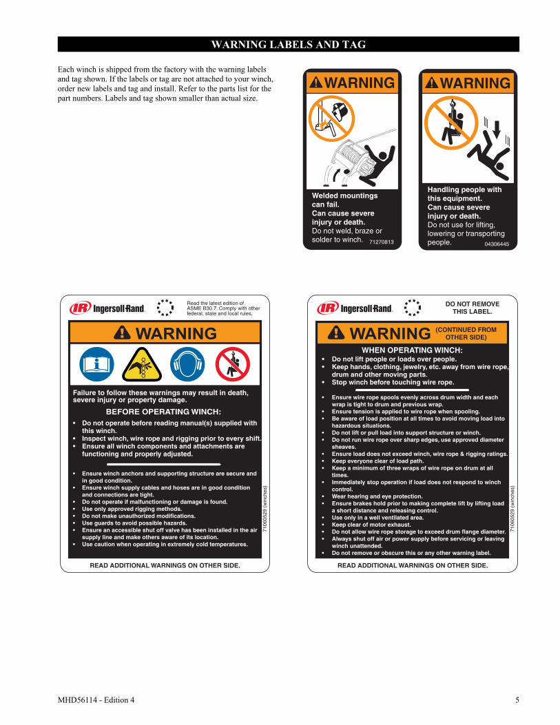
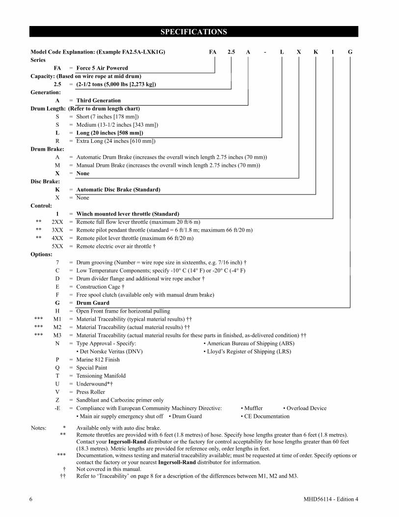
Each winch is shipped from the factory with the warning labels and tag shown. If the labels or tag are not attached to your winch, order new labels and tag and install. Refer to the parts list for the part numbers. Labels and tag shown smaller than actual size.
WARNING
Welded mountingscan fail.Can cause severeinjury or death.Do not weld, braze orsolder to winch. 71270813
WARNING
Handling people withthis equipment.Can cause severeinjury or death.Do not use for lifting,lowering or transportingpeople. 04306445
Read the latest edition ofASME B30.7. Comply with other federal, state and local rules.
READ ADDITIONAL WARNINGS ON OTHER SIDE. READ ADDITIONAL WARNINGS ON OTHER SIDE.
7106
0529
(w
inch
es)
DO NOT REMOVETHIS LABEL.
(CONTINUED FROMOTHER SIDE)
7106
0529
(w
inch
es)
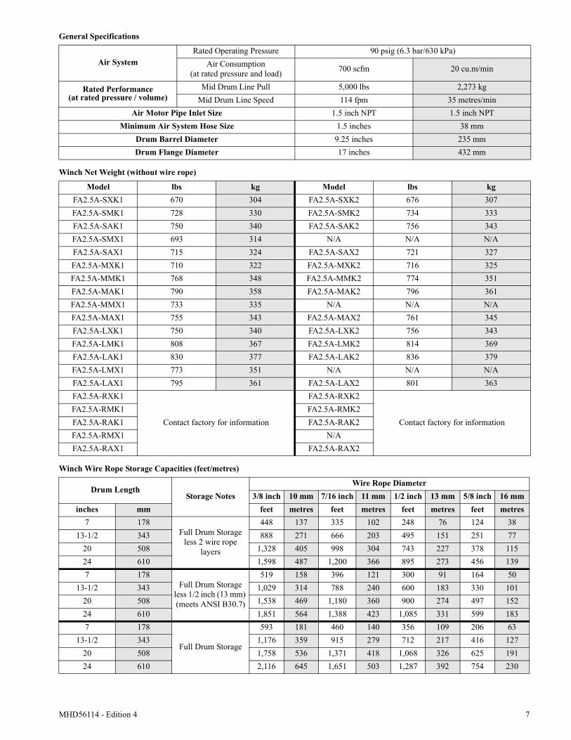
Failure to follow these warnings may result in death, severe injury or property damage.
• Do not operate before reading manual(s) supplied with this winch.
• Inspect winch, wire rope and rigging prior to every shift.• Ensure all winch components and attachments are
functioning and properly adjusted.
• Ensure winch anchors and supporting structure are secure and in good condition.
• Ensure winch supply cables and hoses are in good condition and connections are tight.
• Do not operate if malfunctioning or damage is found.• Use only approved rigging methods.• Do not make unauthorized modifications.• Use guards to avoid possible hazards.• Ensure an accessible shut off valve has been installed in the air
supply line and make others aware of its location.• Use caution when operating in extremely cold temperatures.
BEFORE OPERATING WINCH:
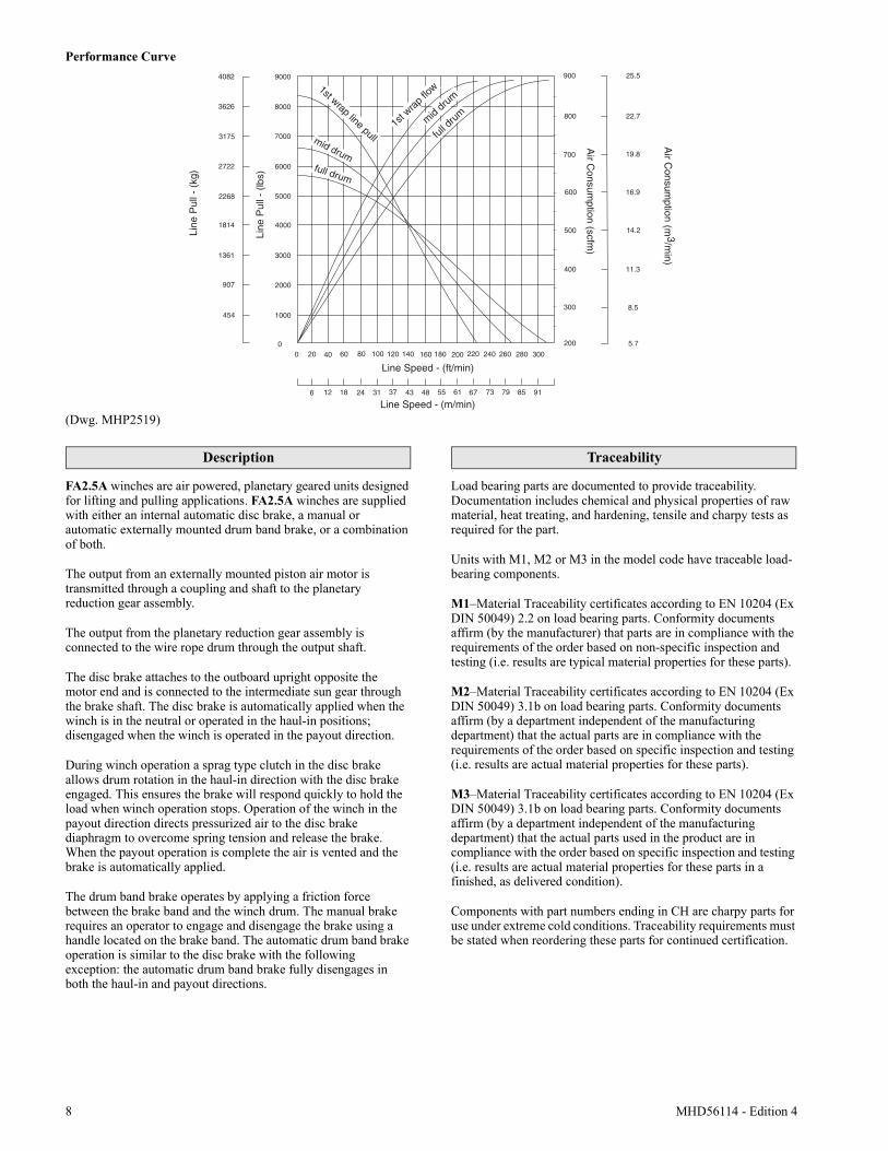
WHEN OPERATING WINCH:• Do not lift people or loads over people.• Keep hands, clothing, jewelry, etc. away from wire rope,
drum and other moving parts.• Stop winch before touching wire rope.
• Ensure wire rope spools evenly across drum width and each wrap is tight to drum and previous wrap.
• Ensure tension is applied to wire rope when spooling.• Be aware of load position at all times to avoid moving load into
hazardous situations.• Do not lift or pull load into support structure or winch.• Do not run wire rope over sharp edges, use approved diameter
sheaves.• Ensure load does not exceed winch, wire rope & rigging ratings.• Keep everyone clear of load path.• Keep a minimum of three wraps of wire rope on drum at all
times.• Immediately stop operation if load does not respond to winch
control.• Wear hearing and eye protection.• Ensure brakes hold prior to making complete lift by lifting load
a short distance and releasing control.• Use only in a well ventilated area.• Keep clear of motor exhaust.• Do not allow wire rope storage to exceed drum flange diameter.• Always shut off air or power supply before servicing or leaving
winch unattended.• Do not remove or obscure this or any other warning label.
6 MHD56114 - Edition 4
SPECIFICATIONS
Model Code Explanation: (Example FA2.5A-LXK1G) FA 2.5 A - L X K 1 GSeries
FA = Force 5 Air PoweredCapacity: (Based on wire rope at mid drum)
2.5 = (2-1/2 tons (5,000 lbs [2,273 kg])Generation:
A = Third GenerationDrum Length: (Refer to drum length chart)
S = Short (7 inches [178 mm])S = Medium (13-1/2 inches [343 mm])L = Long (20 inches [508 mm])R = Extra Long (24 inches [610 mm])
Drum Brake:A = Automatic Drum Brake (increases the overall winch length 2.75 inches (70 mm))M = Manual Drum Brake (increases the overall winch length 2.75 inches (70 mm))X = None
Disc Brake:K = Automatic Disc Brake (Standard)X = None
Control:1 = Winch mounted lever throttle (Standard)
** 2XX = Remote full flow lever throttle (maximum 20 ft/6 m)** 3XX = Remote pilot pendant throttle (standard = 6 ft/1.8 m; maximum 66 ft/20 m)** 4XX = Remote pilot lever throttle (maximum 66 ft/20 m)
5XX = Remote electric over air throttle †Options:
7 = Drum grooving (Number = wire rope size in sixteenths, e.g. 7/16 inch) †C = Low Temperature Components; specify -10° C (14° F) or -20° C (-4° F)D = Drum divider flange and additional wire rope anchor †E = Construction Cage †F = Free spool clutch (available only with manual drum brake)G = Drum Guard H = Open Front frame for horizontal pulling
*** M1 = Material Traceability (typical material results) ††*** M2 = Material Traceability (actual material results) ††*** M3 = Material Traceability (actual material results for these parts in finished, as-delivered condition) ††
N = Type Approval - Specify: • American Bureau of Shipping (ABS)• Det Norske Veritas (DNV) • Lloyd’s Register of Shipping (LRS)
P = Marine 812 FinishQ = Special PaintT = Tensioning ManifoldU = Underwound*†V = Press RollerZ = Sandblast and Carbozinc primer only-E = Compliance with European Community Machinery Directive: • Muffler • Overload Device
• Main air supply emergency shut off • Drum Guard • CE Documentation
Notes: ***
***
†††
Available only with auto disc brake.Remote throttles are provided with 6 feet (1.8 metres) of hose. Specify hose lengths greater than 6 feet (1.8 metres). Contact your Ingersoll-Rand distributor or the factory for control acceptability for hose lengths greater than 60 feet (18.3 metres). Metric lengths are provided for reference only, order lengths in feet.Documentation, witness testing and material traceability available; must be requested at time of order. Specify options or contact the factory or your nearest Ingersoll-Rand distributor for information.Not covered in this manual.Refer to ‘Traceability’ on page 8 for a description of the differences between M1, M2 and M3.
MHD56114 - Edition 4 7
General Specifications
Winch Net Weight (without wire rope)
Winch Wire Rope Storage Capacities (feet/metres)
Air SystemRated Operating Pressure 90 psig (6.3 bar/630 kPa)
Air Consumption(at rated pressure and load) 700 scfm 20 cu.m/min
Rated Performance(at rated pressure / volume)
Mid Drum Line Pull 5,000 lbs 2,273 kgMid Drum Line Speed 114 fpm 35 metres/min
Air Motor Pipe Inlet Size 1.5 inch NPT 1.5 inch NPTMinimum Air System Hose Size 1.5 inches 38 mm
Drum Barrel Diameter 9.25 inches 235 mmDrum Flange Diameter 17 inches 432 mm
Model lbs kg Model lbs kgFA2.5A-SXK1 670 304 FA2.5A-SXK2 676 307FA2.5A-SMK1 728 330 FA2.5A-SMK2 734 333FA2.5A-SAK1 750 340 FA2.5A-SAK2 756 343FA2.5A-SMX1 693 314 N/A N/A N/AFA2.5A-SAX1 715 324 FA2.5A-SAX2 721 327FA2.5A-MXK1 710 322 FA2.5A-MXK2 716 325FA2.5A-MMK1 768 348 FA2.5A-MMK2 774 351FA2.5A-MAK1 790 358 FA2.5A-MAK2 796 361FA2.5A-MMX1 733 335 N/A N/A N/AFA2.5A-MAX1 755 343 FA2.5A-MAX2 761 345FA2.5A-LXK1 750 340 FA2.5A-LXK2 756 343FA2.5A-LMK1 808 367 FA2.5A-LMK2 814 369FA2.5A-LAK1 830 377 FA2.5A-LAK2 836 379FA2.5A-LMX1 773 351 N/A N/A N/AFA2.5A-LAX1 795 361 FA2.5A-LAX2 801 363FA2.5A-RXK1
Contact factory for information
FA2.5A-RXK2
Contact factory for informationFA2.5A-RMK1 FA2.5A-RMK2FA2.5A-RAK1 FA2.5A-RAK2FA2.5A-RMX1 N/AFA2.5A-RAX1 FA2.5A-RAX2
Drum LengthStorage Notes
Wire Rope Diameter3/8 inch 10 mm 7/16 inch 11 mm 1/2 inch 13 mm 5/8 inch 16 mm
inches mm feet metres feet metres feet metres feet metres7 178
Full Drum Storage less 2 wire rope
layers
448 137 335 102 248 76 124 3813-1/2 343 888 271 666 203 495 151 251 77
20 508 1,328 405 998 304 743 227 378 11524 610 1,598 487 1,200 366 895 273 456 1397 178
Full Drum Storage less 1/2 inch (13 mm) (meets ANSI B30.7)
519 158 396 121 300 91 164 5013-1/2 343 1,029 314 788 240 600 183 330 101
20 508 1,538 469 1,180 360 900 274 497 15224 610 1,851 564 1,388 423 1,085 331 599 1837 178
Full Drum Storage
593 181 460 140 356 109 206 6313-1/2 343 1,176 359 915 279 712 217 416 127
20 508 1,758 536 1,371 418 1,068 326 625 19124 610 2,116 645 1,651 503 1,287 392 754 230
8 MHD56114 - Edition 4
Performance Curve
(Dwg. MHP2519)
Description
FA2.5A winches are air powered, planetary geared units designed for lifting and pulling applications. FA2.5A winches are supplied with either an internal automatic disc brake, a manual or automatic externally mounted drum band brake, or a combination of both.
The output from an externally mounted piston air motor is transmitted through a coupling and shaft to the planetary reduction gear assembly.
The output from the planetary reduction gear assembly is connected to the wire rope drum through the output shaft.
The disc brake attaches to the outboard upright opposite the motor end and is connected to the intermediate sun gear through the brake shaft. The disc brake is automatically applied when the winch is in the neutral or operated in the haul-in positions; disengaged when the winch is operated in the payout direction.
During winch operation a sprag type clutch in the disc brake allows drum rotation in the haul-in direction with the disc brake engaged. This ensures the brake will respond quickly to hold the load when winch operation stops. Operation of the winch in the payout direction directs pressurized air to the disc brake diaphragm to overcome spring tension and release the brake. When the payout operation is complete the air is vented and the brake is automatically applied.
The drum band brake operates by applying a friction force between the brake band and the winch drum. The manual brake requires an operator to engage and disengage the brake using a handle located on the brake band. The automatic drum band brake operation is similar to the disc brake with the following exception: the automatic drum band brake fully disengages in both the haul-in and payout directions.
Traceability
Load bearing parts are documented to provide traceability. Documentation includes chemical and physical properties of raw material, heat treating, and hardening, tensile and charpy tests as required for the part.
Units with M1, M2 or M3 in the model code have traceable load-bearing components.
M1–Material Traceability certificates according to EN 10204 (Ex DIN 50049) 2.2 on load bearing parts. Conformity documents affirm (by the manufacturer) that parts are in compliance with the requirements of the order based on non-specific inspection and testing (i.e. results are typical material properties for these parts).
M2–Material Traceability certificates according to EN 10204 (Ex DIN 50049) 3.1b on load bearing parts. Conformity documents affirm (by a department independent of the manufacturing department) that the actual parts are in compliance with the requirements of the order based on specific inspection and testing (i.e. results are actual material properties for these parts).
M3–Material Traceability certificates according to EN 10204 (Ex DIN 50049) 3.1b on load bearing parts. Conformity documents affirm (by a department independent of the manufacturing department) that the actual parts used in the product are in compliance with the order based on specific inspection and testing (i.e. results are actual material properties for these parts in a finished, as delivered condition).
Components with part numbers ending in CH are charpy parts for use under extreme cold conditions. Traceability requirements must be stated when reordering these parts for continued certification.
1000
2000
3000
4000
5000
6000
7000
8000
9000
00 20 40 60 80 100 120 140 160 180 200 220 240 260 280 300
200
300
900
800
700
600
500
400
Line Speed - (ft/min)
Line
Pul
l - (
lbs)
1st wrap line pullmid drumfull drum
1st w
rap f
low
mid dr
um
full d
rum
Line
Pul
l - (
kg)
4082
3626
3175
2722
2268
5.7
8.5
11.3
25.5
22.7
19.8
16.9
14.2
Line Speed - (m/min)6 12 18 24 31 37 43 48 55 61 67 73 79 85 91
1814
1361
907
454
Air C
onsumption (scfm
)
Air C
onsumption (m
3/min)
MHD56114 - Edition 4 9
INSTALLATION
Prior to installing the winch, carefully inspect it for possible shipping damage.Winches are supplied fully lubricated from the factory. Check oil levels and adjust as necessary before operating winch. Refer to “LUBRICATION” section for recommended oils.
CAUTION
• Owners and users are advised to examine specific, local or other regulations, including American National Standards Institute and/or OSHA Regulations which may apply to a particular type of use of this product before installing or putting winch to use.
Mounting
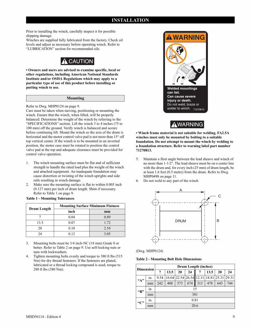
Refer to Dwg. MHP0124 on page 9.Care must be taken when moving, positioning or mounting the winch. Ensure that the winch, when lifted, will be properly balanced. Determine the weight of the winch by referring to the “SPECIFICATIONS” section. Lift the winch 3 to 4 inches (75 to 100 mm) off the ground. Verify winch is balanced and secure before continuing lift. Mount the winch so the axis of the drum is horizontal and the motor control valve pad is not more than 15° off top vertical center. If the winch is to be mounted in an inverted position, the motor case must be rotated to position the control valve pad at the top and adequate clearance must be provided for control valve operation.
1. The winch mounting surface must be flat and of sufficient strength to handle the rated load plus the weight of the winch and attached equipment. An inadequate foundation may cause distortion or twisting of the winch uprights and side rails resulting in winch damage.
2. Make sure the mounting surface is flat to within 0.005 inch (0.127 mm) per inch of drum length. Shim if necessary. Refer to Table 1 on page 9.
3. Mounting bolts must be 3/4 inch-NC (18 mm) Grade 8 or better. Refer to Table 2 on page 9. Use self-locking nuts or nuts with lockwashers.
4. Tighten mounting bolts evenly and torque to 380 ft lbs (515 Nm) for dry thread fasteners. If the fasteners are plated, lubricated or a thread locking compound is used, torque to 280 ft lbs (380 Nm).
WARNING• Winch frame material is not suitable for welding. FA2.5A winches must only be mounted by bolting to a suitable foundation. Do not attempt to mount the winch by welding to a foundation structure. Refer to warning label part number 71270813.
5. Maintain a fleet angle between the lead sheave and winch of no more than 1-1/2°. The lead sheave must be on a center line with the drum and, for every inch (25 mm) of drum length, be at least 1.6 feet (0.5 metre) from the drum. Refer to Dwg. MHP0498 on page 11.
6. Do not weld to any part of the winch.
(Dwg. MHP0124)
Table 1 - Mounting Tolerances
Drum LengthMounting Surface Minimum Flatness
inch mm7 0.04 0.89
13.5 0.07 1.7220 0.10 2.5424 0.12 3.05
Table 2 - Mounting Bolt Hole Dimensions
DimensionDrum Length (inches)
7 13.5 20 24 7 13.5 20 24
“A”in. 9.54 16.04 22.54 26.54 12.31 18.81 25.31 29.31
mm 242 408 573 674 313 478 643 744
“B”in. 15
mm 381
“C”in. 0.81
mm 20.6
WARNING
Welded mountingscan fail.Can cause severeinjury or death.Do not weld, braze orsolder to winch. 71270813
10 MHD56114 - Edition 4
Wire Rope
CAUTION• Maintain at least 3 tight wraps of wire rope on the drum at all times. Refer to Dwg. MHP0498 on page 11.
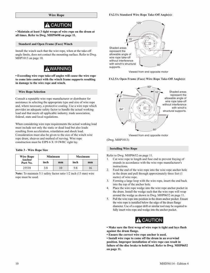
Standard and Open Frame (Face) Winch
Install the winch such that the wire rope, when at the take-off angle limits, does not contact the mounting surface. Refer to Dwg. MHP1013 on page 10.
WARNING• Exceeding wire rope take-off angles will cause the wire rope to come into contact with the winch frame supports resulting in damage to the wire rope and winch.
Wire Rope Selection
Consult a reputable wire rope manufacturer or distributor for assistance in selecting the appropriate type and size of wire rope and, where necessary, a protective coating. Use a wire rope which provides an adequate safety factor to handle the actual working load and that meets all applicable industry, trade association, federal, state and local regulations.
When considering wire rope requirements the actual working load must include not only the static or dead load but also loads resulting from acceleration, retardation and shock load. Consideration must also be given to the size of the winch wire rope drum, sheaves and method of reeving. Wire rope construction must be EIPS 6 X 19 IWRC right lay.
Note: To maintain 5:1 safety factor ratio 1/2 inch (13 mm) wire rope must be used.
(Dwg. MHP1013)
Installing Wire Rope
Refer to Dwg. MHP0652 on page 11.1. Cut wire rope to length and fuse end to prevent fraying of
strands in accordance with the wire rope manufacturer's instructions.
2. Feed the end of the wire rope into the wire rope anchor hole in the drum and pull through approximately three feet (1 metre) of wire rope.
3. Forming a large loop with the wire rope, insert the end back into the top of the anchor hole.
4. Place the wire rope wedge into the wire rope anchor pocket in the drum. Install the wedge such that the wire rope will wrap around the wedge as shown in Dwg. MHP0652 on page 11.
5. Pull the wire rope into position in the drum anchor pocket. Ensure the wire rope is installed below the edge of the drum flange diameter. Use of a copper drift or similar tool may be required to fully insert wire rope and wedge into the anchor pocket.
CAUTION
• Make sure the first wrap of wire rope is tight and lays flush against the drum flange.• Ensure the correct wire rope anchor is used.• Install wire rope to come off the drum in an overwind position. Improper installation of wire rope can result in failure of the disc brake to hold load. Refer to Dwg. MHP0652 on page 11.
Table 3 - Wire Rope Size
Wire RopeAnchor Part No.
Minimum Maximum
inch mm inch mm
25539 3/8 10 5/8 16
MHD56114 - Edition 4 11
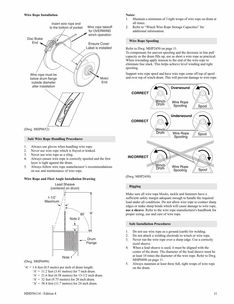
Wire Rope Installation
(Dwg. MHP0652)
Safe Wire Rope Handling Procedures
1. Always use gloves when handling wire rope.2. Never use wire rope which is frayed or kinked.3. Never use wire rope as a sling.4. Always ensure wire rope is correctly spooled and the first
layer is tight against the drum.5. Always follow wire rope manufacturer’s recommendations
on use and maintenance of wire rope.
Wire Rope and Fleet Angle Installation Drawing
(Dwg. MHP0498)
‘A’ = 1.6 feet (0.5 metre) per inch of drum length:‘A’ = 11.2 feet (3.41 metres) for 7 inch drum.‘A’ = 21.6 feet (6.58 metres) for 13-1/2 inch drum.‘A’ = 32 feet (9.75 metres) for 20 inch drum.‘A’ = 38.4 feet (11.7 metres) for 24 inch drum.
Notes:1. Maintain a minimum of 3 tight wraps of wire rope on drum at
all times.2. Refer to “Winch Wire Rope Storage Capacities” for
additional information.
Wire Rope Spooling
Refer to Dwg. MHP2450 on page 11.To compensate for uneven spooling and the decrease in line pull capacity as the drum fills up, use as short a wire rope as practical. When rewinding apply tension to the end of the wire rope to eliminate line slack. This helps achieve level winding and tight spooling.
Support wire rope spool and have wire rope come off top of spool and over top of winch drum. This will prevent damage to wire rope.
(Dwg. MHP2450)
Rigging
Make sure all wire rope blocks, tackle and fasteners have a sufficient safety margin adequate enough to handle the required load under all conditions. Do not allow wire rope to contact sharp edges or make sharp bends which will cause damage to wire rope, use a sheave. Refer to the wire rope manufacturer's handbook for proper sizing, use and care of wire rope.
Safe Installation Procedures
1. Do not use wire rope as a ground (earth) for welding.2. Do not attach a welding electrode to winch or wire rope.3. Never run the wire rope over a sharp edge. Use a correctly
sized sheave.4. When a lead sheave is used, it must be aligned with the
center of the drum. The diameter of the lead sheave must be at least 18 times the diameter of the wire rope. Refer to Dwg. MHP0498 on page 11.
5. Always maintain at least three full, tight wraps of wire rope on the drum.
Lead Sheave(centered on drum)
1-1/2˚Maximum
Note 2
Note 1
‘A’
DrumFlange
90˚
CORRECT
Wire RopeSpooling
Wire RopeSpooling
Wire RopeSpooling
Spool
INCORRECT
WinchDrum
SpoolWinchDrum
CORRECT
Underwound
Overwound
SpoolWinchDrum
12 MHD56114 - Edition 4
Air Supply
The air supply must be clean, free from moisture and lubricated to ensure optimum motor performance. Foreign particles, moisture and lack of lubrication are the primary causes of premature motor wear and breakdown. Using an air filter, lubricator and moisture separator will improve overall winch performance and reduce unscheduled down time.The air consumption is 700 scfm (20 cu. m/min) at rated operating pressure of 90 psig (6.3 bar/630 kPa) at the winch motor inlet. If air supply varies from recommended, then winch performance will change.
Air Lines
The inside diameter of the winch air supply lines must be at least 1-1/2 inch (38 mm). Before making final connections, all air supply lines should be purged with clean, moisture free air or nitrogen before connecting to winch inlet. Supply lines should be as short and straight as installation conditions will permit. Long transmission lines and excessive use of fittings, elbows, tees, globe valves etc. cause a reduction in pressure due to restrictions and surface friction in the lines.
Air Line Lubricator
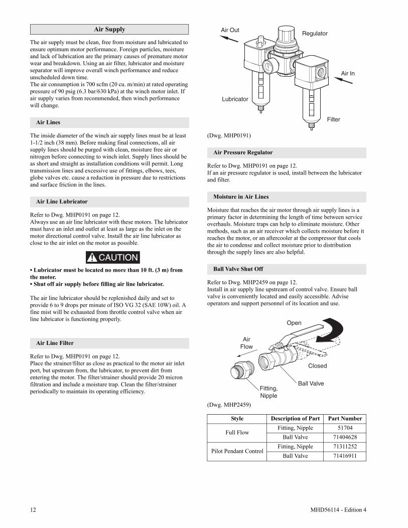
Refer to Dwg. MHP0191 on page 12.Always use an air line lubricator with these motors. The lubricator must have an inlet and outlet at least as large as the inlet on the motor directional control valve. Install the air line lubricator as close to the air inlet on the motor as possible.
CAUTION• Lubricator must be located no more than 10 ft. (3 m) from the motor.• Shut off air supply before filling air line lubricator.
The air line lubricator should be replenished daily and set to provide 6 to 9 drops per minute of ISO VG 32 (SAE 10W) oil. A fine mist will be exhausted from throttle control valve when air line lubricator is functioning properly.
Air Line Filter
Refer to Dwg. MHP0191 on page 12.Place the strainer/filter as close as practical to the motor air inlet port, but upstream from, the lubricator, to prevent dirt from entering the motor. The filter/strainer should provide 20 micron filtration and include a moisture trap. Clean the filter/strainer periodically to maintain its operating efficiency.
(Dwg. MHP0191)
Air Pressure Regulator
Refer to Dwg. MHP0191 on page 12.If an air pressure regulator is used, install between the lubricator and filter.
Moisture in Air Lines
Moisture that reaches the air motor through air supply lines is a primary factor in determining the length of time between service overhauls. Moisture traps can help to eliminate moisture. Other methods, such as an air receiver which collects moisture before it reaches the motor, or an aftercooler at the compressor that cools the air to condense and collect moisture prior to distribution through the supply lines are also helpful.
Ball Valve Shut Off
Refer to Dwg. MHP2459 on page 12.Install in air supply line upstream of control valve. Ensure ball valve is conveniently located and easily accessible. Advise operators and support personnel of its location and use.
(Dwg. MHP2459)
Style Description of Part Part Number
Full FlowFitting, Nipple 51704
Ball Valve 71404628
Pilot Pendant ControlFitting, Nipple 71311252
Ball Valve 71416911
Lubricator
Air Out Regulator
Air In
Filter
Open
Closed
Ball Valve
AirFlow
Fitting,Nipple
MHD56114 - Edition 4 13
Mufflers
Make sure mufflers are installed in winch exhaust manifold and control valve exhaust port. An additional muffler is used on winches equipped with an emergency stop and overload device. Check mufflers periodically to ensure they are functioning correctly.
Motor
For optimum performance and maximum durability of parts, provide a lubricated air supply of 700 scfm (20 cu. m/min) at 90 psig (6.3 bar/630 kPa). Recommended pressures and volumes are measured at the point of entry to the air motor directional control valve.
Emergency Stop and Overload System
Refer to Dwg. MHP2434 on page 54.Air supply line is connected to air control valve. When emergency stop or overload valve is activated, all winch movement will stop.
CAUTION• If winch continues to move (payout load) after emergency stop activates, brake(s) are not holding load and may require adjustment or repair.
When control valve senses a preset pressure difference between ports, a pilot signal is sent to stop flow of air, all winch movement will stop.
Initial Winch Operating Checks
Winches are tested for proper operation prior to leaving the factory. Before the winch is placed into service the following initial operating checks should be performed. 1. When first running the motor inject some light oil into the
inlet connection to provide initial lubrication.2. When first operating the winch it is recommended that the
motor be driven slowly in both directions for a few minutes.
For winches that have been in storage the following start-up procedures are required.1. Give the winch an inspection conforming to the requirements of
“Winches Not in Regular Use” in the “INSPECTION” section.2. Pour a small amount of ISO VG 32 (SAE 10W) oil in the
motor inlet port.3. Operate the motor for 10 seconds in both directions to flush
out any impurities.4. Check to ensure oil levels are “full”.5. The winch is now ready for normal use.
14 MHD56114 - Edition 4
OPERATION
It is recommended that the user and owner check all appropriate and applicable regulations before placing this product into use.
The four most important aspects of winch operation are:1. Follow all safety instructions when operating the winch.2. Allow only people trained in safety and operation of this
winch to operate this equipment.3. Subject each winch to a regular inspection and maintenance
procedure.4. Be aware of the winch capacity and weight of load at all
times.
CAUTIONCAUTION
• To avoid damage to the rigging, the structure supporting the rigging and the winch, do not “two-block*” the end of the wire rope.
* Two blocking occurs when the winch wire rope is multi reeved using two separate sheave blocks which are allowed to come into contact with each other during winch operation. When this occurs extreme forces are exerted on the wire rope and sheave blocks which may result in equipment and or rigging failure.
WARNINGWARNING
• The winch is not designed or suitable for lifting, lowering or moving people. Never lift loads over people.
Operators must be physically competent. Operators must not have a health condition which might affect their ability to act, and they must have good hearing, vision and depth perception. The winch operator must be carefully instructed in his duties and must understand the operation of the winch, including a study of the manufacturer’s literature. The operator must thoroughly understand proper methods of hitching loads and must have a good attitude regarding safety. It is the operator’s responsibility to refuse to operate the winch under unsafe conditions.
Winch Controls
A spring loaded, motor mounted, manual throttle control valve is supplied as a standard feature on these winches. Optional remote pendant controls are also available. Reference the model code on the winch nameplate and compare it to the “SPECIFICATIONS” section on page 6 to determine winch configuration. The throttle control provides operator control of the motor speed and direction of drum rotation.Operate winch throttle control using smooth, even movements. Do not slam or jerk throttle controls during operation.
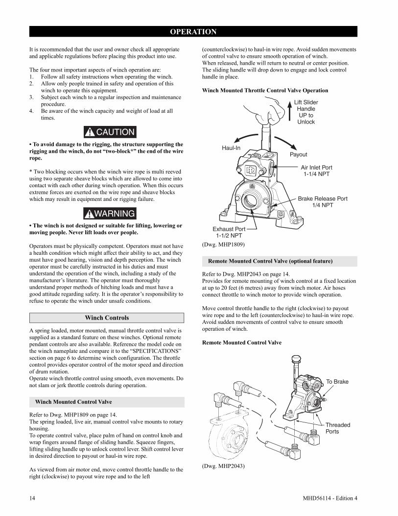
Winch Mounted Control Valve
Refer to Dwg. MHP1809 on page 14.The spring loaded, live air, manual control valve mounts to rotary housing.To operate control valve, place palm of hand on control knob and wrap fingers around flange of sliding handle. Squeeze fingers, lifting sliding handle up to unlock control lever. Shift control lever in desired direction to payout or haul-in wire rope.
As viewed from air motor end, move control throttle handle to the right (clockwise) to payout wire rope and to the left
(counterclockwise) to haul-in wire rope. Avoid sudden movements of control valve to ensure smooth operation of winch.When released, handle will return to neutral or center position. The sliding handle will drop down to engage and lock control handle in place.
Winch Mounted Throttle Control Valve Operation
(Dwg. MHP1809)
Remote Mounted Control Valve (optional feature)
Refer to Dwg. MHP2043 on page 14.Provides for remote mounting of winch control at a fixed location at up to 20 feet (6 metres) away from winch motor. Air hoses connect throttle to winch motor to provide winch operation.
Move control throttle handle to the right (clockwise) to payout wire rope and to the left (counterclockwise) to haul-in wire rope. Avoid sudden movements of control valve to ensure smooth operation of winch.
Remote Mounted Control Valve
(Dwg. MHP2043)
Haul-In
Brake Release Port1/4 NPT
Air Inlet Port1-1/4 NPT
Payout
Lift SliderHandleUP toUnlock
Exhaust Port1-1/2 NPT
To Brake
ThreadedPorts
MHD56114 - Edition 4 15
Remote Pilot Pendant Control (optional feature)
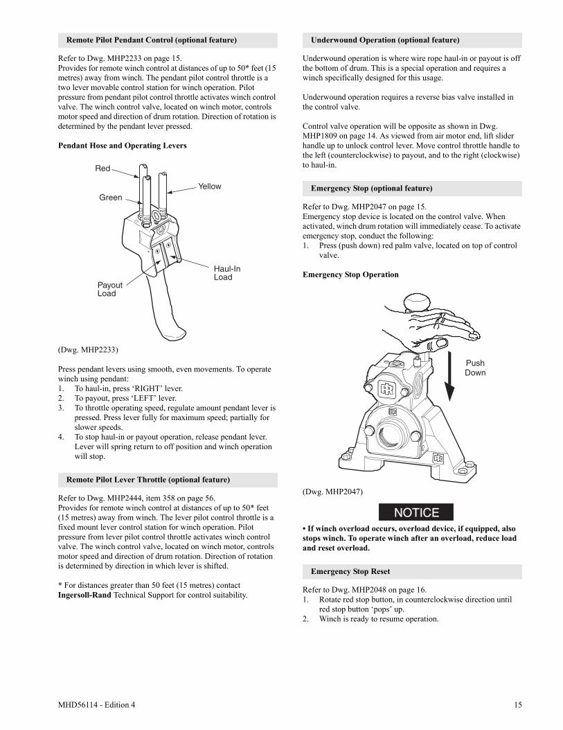
Refer to Dwg. MHP2233 on page 15.Provides for remote winch control at distances of up to 50* feet (15 metres) away from winch. The pendant pilot control throttle is a two lever movable control station for winch operation. Pilot pressure from pendant pilot control throttle activates winch control valve. The winch control valve, located on winch motor, controls motor speed and direction of drum rotation. Direction of rotation is determined by the pendant lever pressed.
Pendant Hose and Operating Levers
(Dwg. MHP2233)
Press pendant levers using smooth, even movements. To operate winch using pendant:1. To haul-in, press ‘RIGHT’ lever.2. To payout, press ‘LEFT’ lever.3. To throttle operating speed, regulate amount pendant lever is
pressed. Press lever fully for maximum speed; partially for slower speeds.
4. To stop haul-in or payout operation, release pendant lever. Lever will spring return to off position and winch operation will stop.
Remote Pilot Lever Throttle (optional feature)
Refer to Dwg. MHP2444, item 358 on page 56.Provides for remote winch control at distances of up to 50* feet (15 metres) away from winch. The lever pilot control throttle is a fixed mount lever control station for winch operation. Pilot pressure from lever pilot control throttle activates winch control valve. The winch control valve, located on winch motor, controls motor speed and direction of drum rotation. Direction of rotation is determined by direction in which lever is shifted.
* For distances greater than 50 feet (15 metres) contact Ingersoll-Rand Technical Support for control suitability.
Underwound Operation (optional feature)
Underwound operation is where wire rope haul-in or payout is off the bottom of drum. This is a special operation and requires a winch specifically designed for this usage.
Underwound operation requires a reverse bias valve installed in the control valve.
Control valve operation will be opposite as shown in Dwg. MHP1809 on page 14. As viewed from air motor end, lift slider handle up to unlock control lever. Move control throttle handle to the left (counterclockwise) to payout, and to the right (clockwise) to haul-in.
Emergency Stop (optional feature)
Refer to Dwg. MHP2047 on page 15.Emergency stop device is located on the control valve. When activated, winch drum rotation will immediately cease. To activate emergency stop, conduct the following:1. Press (push down) red palm valve, located on top of control
valve.
Emergency Stop Operation
(Dwg. MHP2047)
NOTICE• If winch overload occurs, overload device, if equipped, also stops winch. To operate winch after an overload, reduce load and reset overload.
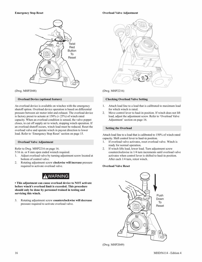
Emergency Stop Reset
Refer to Dwg. MHP2048 on page 16.1. Rotate red stop button, in counterclockwise direction until
red stop button ‘pops’ up.2. Winch is ready to resume operation.
PayoutLoad
Haul-InLoad
Red
GreenYellow
16 MHD56114 - Edition 4
Emergency Stop Reset
(Dwg. MHP2048)
Overload Device (optional feature)
An overload device is available on winches with the emergency shutoff option. Overload device operation is based on differential pressure between air motor inlet and exhaust. The overload device is factory preset to actuate at 150% (± 25%) of winch rated capacity. When an overload condition is sensed, the valve poppet closes, to cut off supply air to winch, stopping winch operation. If an overload shutoff occurs, winch load must be reduced. Reset the overload valve and operate winch in payout direction to lower load. Refer to ‘Emergency Stop Reset’ section on page 15.
Overload Valve Adjustment
Refer to Dwg. MHP2216 on page 16.5/16 in. or 8 mm open ended wrench required.1. Adjust overload valve by turning adjustment screw located at
bottom of control valve.2. Rotating adjustment screw clockwise will increase pressure
required to activate overload valve.
WARNING• This adjustment can cause overload device to NOT activate before winch’s overload limit is exceeded. This procedure should only be done by personnel trained in testing and servicing this winch.
3. Rotating adjustment screw counterclockwise will decrease pressure required to activate overload valve.
Overload Valve Adjustment
(Dwg. MHP2216)
Checking Overload Valve Setting
1. Attach load line to a load that is calibrated to maximum load for which winch is rated.
2. Move control lever to haul-in position. If winch does not lift load, adjust the adjustment screw. Refer to ‘Overload Valve Adjustment’ section on page 16.
Setting the Overload
Attach load line to a load that is calibrated to 150% of winch rated capacity. Shift control lever to haul-in position.1. If overload valve activates, reset overload valve. Winch is
ready for normal operation.2. If winch lifts load, lower load. Turn adjustment screw
counterclockwise in 1/4 turn increments until overload valve activates when control lever is shifted to haul-in position. After each 1/4 turn, retest winch.
Overload Valve Reset
(Dwg. MHP2049)
MHD56114 - Edition 4 17
Winch Brakes
Automatic Disc Brake
The automatic disc brake is a spring applied, air released brake. When the winch is operated in the payout direction air pressure acting on the diaphragm overcomes spring pressure and releases the brake. The brake automatically engages when winch operation is returned from the payout direction to neutral or when shifted to the haul-in direction. When the winch is in the neutral or haul-in positions the brake air is vented and the brake springs apply the brake. The springs, acting on the pressure plate, compress the brake friction and separator plates and engage the brake to prevent drum rotation in the payout direction.The cam type sprag clutch assembly allows drum rotation in the haul-in direction with the brake plates engaged, but prevents the drum from rotating in the payout direction.Disc brake adjustment is not required. If the disc brake does not operate properly it must be disassembled, inspected and repaired.
WARNING• If the brake is disassembled, the friction and separator plates must be correctly installed as shown in the “MAINTENANCE” section of this manual. Failure to correctly install the friction and separator plates can cause the brake to slip.
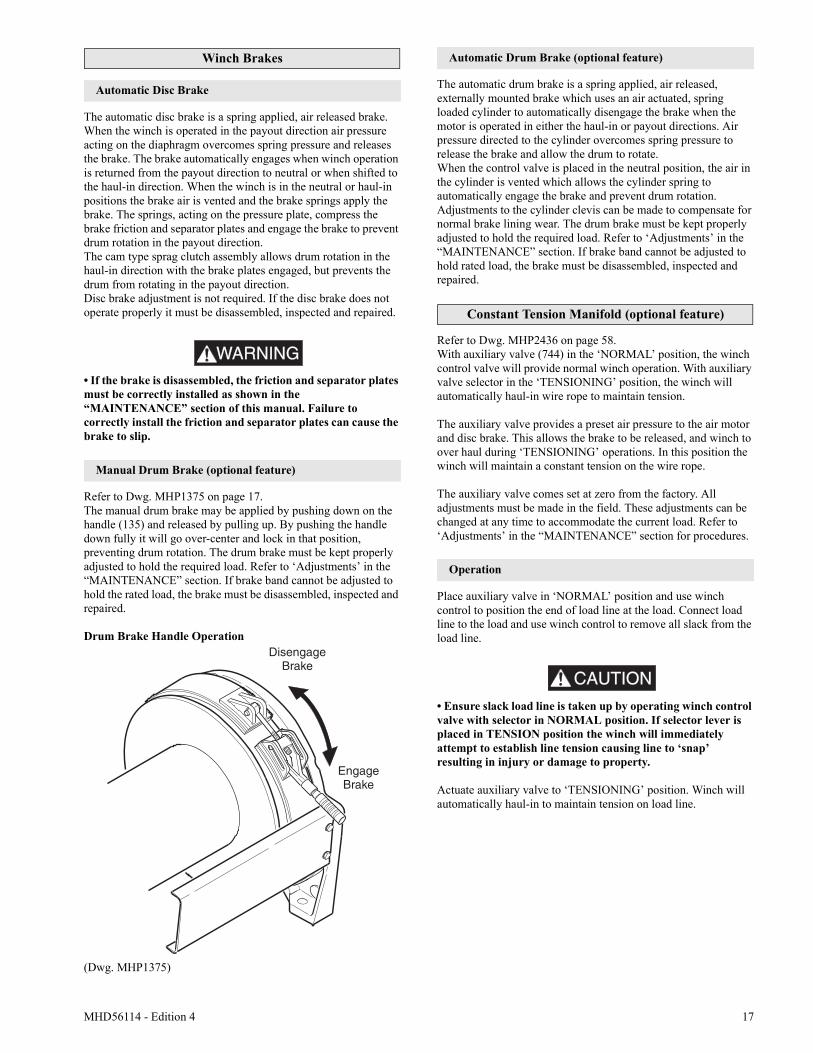
Manual Drum Brake (optional feature)
Refer to Dwg. MHP1375 on page 17.The manual drum brake may be applied by pushing down on the handle (135) and released by pulling up. By pushing the handle down fully it will go over-center and lock in that position, preventing drum rotation. The drum brake must be kept properly adjusted to hold the required load. Refer to ‘Adjustments’ in the “MAINTENANCE” section. If brake band cannot be adjusted to hold the rated load, the brake must be disassembled, inspected and repaired.
Drum Brake Handle Operation
(Dwg. MHP1375)
Automatic Drum Brake (optional feature)
The automatic drum brake is a spring applied, air released, externally mounted brake which uses an air actuated, spring loaded cylinder to automatically disengage the brake when the motor is operated in either the haul-in or payout directions. Air pressure directed to the cylinder overcomes spring pressure to release the brake and allow the drum to rotate.When the control valve is placed in the neutral position, the air in the cylinder is vented which allows the cylinder spring to automatically engage the brake and prevent drum rotation.Adjustments to the cylinder clevis can be made to compensate for normal brake lining wear. The drum brake must be kept properly adjusted to hold the required load. Refer to ‘Adjustments’ in the “MAINTENANCE” section. If brake band cannot be adjusted to hold rated load, the brake must be disassembled, inspected and repaired.
Constant Tension Manifold (optional feature)
Refer to Dwg. MHP2436 on page 58.With auxiliary valve (744) in the ‘NORMAL’ position, the winch control valve will provide normal winch operation. With auxiliary valve selector in the ‘TENSIONING’ position, the winch will automatically haul-in wire rope to maintain tension.
The auxiliary valve provides a preset air pressure to the air motor and disc brake. This allows the brake to be released, and winch to over haul during ‘TENSIONING’ operations. In this position the winch will maintain a constant tension on the wire rope.
The auxiliary valve comes set at zero from the factory. All adjustments must be made in the field. These adjustments can be changed at any time to accommodate the current load. Refer to ‘Adjustments’ in the “MAINTENANCE” section for procedures.
Operation
Place auxiliary valve in ‘NORMAL’ position and use winch control to position the end of load line at the load. Connect load line to the load and use winch control to remove all slack from the load line.
CAUTION
• Ensure slack load line is taken up by operating winch control valve with selector in NORMAL position. If selector lever is placed in TENSION position the winch will immediately attempt to establish line tension causing line to ‘snap’ resulting in injury or damage to property.
Actuate auxiliary valve to ‘TENSIONING’ position. Winch will automatically haul-in to maintain tension on load line.
18 MHD56114 - Edition 4
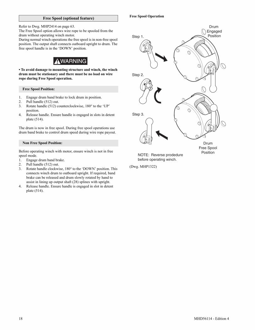
Free Spool (optional feature)
Refer to Dwg. MHP2414 on page 63.The Free Spool option allows wire rope to be spooled from the drum without operating winch motor.During normal winch operations the free spool is in non-free spool position. The output shaft connects outboard upright to drum. The free spool handle is in the ‘DOWN’ position.
WARNING• To avoid damage to mounting structure and winch, the winch drum must be stationary and there must be no load on wire rope during Free Spool operation.
Free Spool Position:
1. Engage drum band brake to lock drum in position. 2. Pull handle (512) out.3. Rotate handle (512) counterclockwise, 180° to the ‘UP’
position.4. Release handle. Ensure handle is engaged in slots in detent
plate (514).
The drum is now in free spool. During free spool operations use drum band brake to control drum speed during wire rope payout.
Non Free Spool Position:
Before operating winch with motor, ensure winch is not in free spool mode.1. Engage drum band brake.2. Pull handle (512) out.3. Rotate handle clockwise, 180° to the ‘DOWN’ position. This
connects winch drum to outboard upright. If required, band brake can be released and drum slowly rotated by hand to assist in lining up output shaft (28) splines with upright.
4. Release handle. Ensure handle is engaged in slot in detent plate (514).
Free Spool Operation
(Dwg. MHP1322)
Drum EngagedPositionStep 1.
Step 2.
Step 3.
DrumFree Spool
PositionNOTE: Reverse prodedure before operating winch.
MHD56114 - Edition 4 19
INSPECTION
Inspection information is based in part on American Society of Mechanical Engineers (ASME B30.7).
WARNING• All new, altered or modified equipment should be inspected and tested by personnel instructed in safety, operation and maintenance of this equipment to ensure safe operation at rated specifications before placing equipment in service.• Never use a winch that inspection indicates is damaged.
Frequent and periodic inspections should be performed on equipment in regular service. Frequent inspections are visual examinations performed by operators or personnel trained in safety and operation of this equipment and include observations made during routine equipment operation. Periodic inspections are thorough inspections conducted by personnel trained in the safety, operation and maintenance of this equipment.ASME B30.7 states inspection intervals depend upon the nature of the critical components of the equipment and the severity of usage. The inspection intervals recommended in this manual are based on intermittent operation of the winch eight hours each day, five days per week, in an environment relatively free of dust, moisture, and corrosive fumes. If the winch is operated almost continuously or more than the eight hours each day, more frequent inspections will be required.Careful inspection on a regular basis will reveal potentially dangerous conditions while still in the early stages, allowing corrective action to be taken before the condition becomes dangerous.Deficiencies revealed through inspection, or noted during operation, must be reported to designated personnel instructed in safety, operation and maintenance of this equipment. A determination as to whether a condition constitutes a safety hazard must be decided, and the correction of noted safety hazards accomplished and documented by written report before placing the equipment in service.
Records and Reports
Inspection records, listing all points requiring periodic inspection should be maintained for all load bearing equipment. Written reports, based on severity of service, should be made on the condition of critical parts as a method of documenting periodic inspections. These reports should be dated, signed by the person who performed the inspection, and kept on file where they are readily available for authorized review.
Wire Rope Reports
Records should be maintained as part of a long-range wire rope inspection program. Records should include the condition of wire rope removed from service. Accurate records will establish a relationship between visual observations noted during frequent inspections and the actual condition of wire rope as determined by periodic inspections.
Frequent Inspection
On equipment in continuous service, frequent inspection should be made by operators at the beginning of each shift. In addition, visual inspections should be conducted during regular operation for indications of damage or evidence of malfunction (such as abnormal noises).1. WINCH. Prior to operation, visually inspect winch housings,
controls, brakes, side rails, uprights and drum for indications of damage. Any discrepancies noted must be reviewed and inspected further by authorized personnel instructed in the operation, safety and maintenance of this winch.
2. WIRE ROPE. Visually inspect all wire rope which can be expected to be in use during the day’s operations. Inspect for wear and damage indicated by distortion of wire rope such as kinking, “birdcaging,” core protrusion, main strand displacement, corrosion, broken or cut strands. If damage is evident, do not operate winch until the discrepancies have been reviewed and inspected further by personnel knowledgeable on wire rope safety and maintenance procedures.
NOTICE• The full extent of wire rope wear cannot be determined by visual inspection. At any indication of wear inspect the wire rope in accordance with instructions in “Periodic Inspection.”
3. AIR SYSTEM. Visually inspect all connections, fittings, hoses and components for indication of air leaks. Repair any leaks or damage.
4. BRAKES. During winch operation test brakes. Brakes must hold load without slipping. Automatic brakes must release when winch motor throttle or pendant is operated. If brakes do not hold load, or do not release properly, the brakes must be adjusted or repaired.
5. WIRE ROPE REEVING. Check reeving and ensure wire rope is properly secured to the drum. Do not operate the winch unless the wire rope feeds onto the drum smoothly.
6. LUBRICATION. Refer to the “LUBRICATION” section for recommended procedures and lubricants.
7. PENDANT (optional feature). Ensure operation of pendant buttons are smooth and that winch is responsive to pendant control. Pendant buttons must spring return to neutral position when released.
8. MANUAL THROTTLE LEVER. Ensure operation of manual throttle lever is smooth and winch is responsive to lever movement. Lever must return to neutral when released. If winch responds slowly or control sticks, do not operate winch until all problems have been corrected.
9. MOTOR. During operation check motor housing for excess heat build up. Housing should not be hot to the touch. Listen for grinding or knocking noises in the motor. There should be no grinding or knocking noises. Ensure lubricated air supply provides 6 to 9 drops per minute of ISO VG 32 (10W) oil. Operate motor slowly in both directions to verify operation.
20 MHD56114 - Edition 4
Periodic Inspection
Periodic inspection intervals for winch use under various conditions is listed below:
Disassembly may be required as a result of frequent inspection findings or in order to properly inspect the individual components. Disassembly steps are described in the “MAINTENANCE” section. Maintain written records of periodic inspections to provide an accumulative basis for continuing evaluation. Inspect all items listed in ‘Frequent Inspection.’ Also inspect the following:1. SIDE RAILS and UPRIGHTS. Check for deformed, cracked
or corroded main components. Replace damaged parts.2. FASTENERS. Check retainer rings, split pins, capscrews,
nuts and other fasteners on winch, including mounting bolts. Replace if missing or damaged and tighten if loose.
3. DRUM and SHEAVES. Check for cracks, wear or damage. Replace if necessary.
4. WIRE ROPE. In addition to “Frequent Inspection” requirements, also inspect for the following:a. Build-up of dirt and corrosion. Clean with steam or a
stiff wire brush to remove dirt and corrosion if necessary.
b. Loose or damaged end connection. Replace ifloose or damaged.
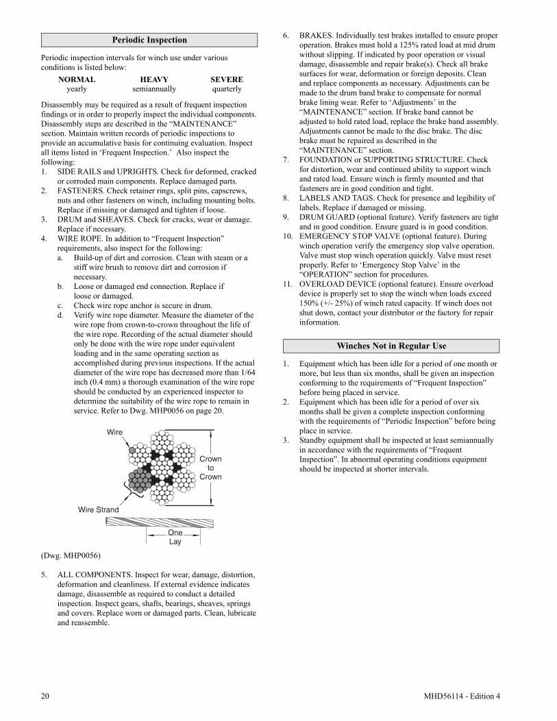
c. Check wire rope anchor is secure in drum.d. Verify wire rope diameter. Measure the diameter of the
wire rope from crown-to-crown throughout the life of the wire rope. Recording of the actual diameter should only be done with the wire rope under equivalent loading and in the same operating section as accomplished during previous inspections. If the actual diameter of the wire rope has decreased more than 1/64 inch (0.4 mm) a thorough examination of the wire rope should be conducted by an experienced inspector to determine the suitability of the wire rope to remain in service. Refer to Dwg. MHP0056 on page 20.
(Dwg. MHP0056)
5. ALL COMPONENTS. Inspect for wear, damage, distortion, deformation and cleanliness. If external evidence indicates damage, disassemble as required to conduct a detailed inspection. Inspect gears, shafts, bearings, sheaves, springs and covers. Replace worn or damaged parts. Clean, lubricate and reassemble.
6. BRAKES. Individually test brakes installed to ensure proper operation. Brakes must hold a 125% rated load at mid drum without slipping. If indicated by poor operation or visual damage, disassemble and repair brake(s). Check all brake surfaces for wear, deformation or foreign deposits. Cleanand replace components as necessary. Adjustments can be made to the drum band brake to compensate for normal brake lining wear. Refer to ‘Adjustments’ in the “MAINTENANCE” section. If brake band cannot be adjusted to hold rated load, replace the brake band assembly. Adjustments cannot be made to the disc brake. The disc brake must be repaired as described in the “MAINTENANCE” section.
7. FOUNDATION or SUPPORTING STRUCTURE. Checkfor distortion, wear and continued ability to support winch and rated load. Ensure winch is firmly mounted and that fasteners are in good condition and tight.
8. LABELS AND TAGS. Check for presence and legibility of labels. Replace if damaged or missing.
9. DRUM GUARD (optional feature). Verify fasteners are tight and in good condition. Ensure guard is in good condition.
10. EMERGENCY STOP VALVE (optional feature). During winch operation verify the emergency stop valve operation. Valve must stop winch operation quickly. Valve must reset properly. Refer to ‘Emergency Stop Valve’ in the “OPERATION” section for procedures.
11. OVERLOAD DEVICE (optional feature). Ensure overload device is properly set to stop the winch when loads exceed 150% (+/- 25%) of winch rated capacity. If winch does not shut down, contact your distributor or the factory for repair information.
Winches Not in Regular Use
1. Equipment which has been idle for a period of one month or more, but less than six months, shall be given an inspection conforming to the requirements of “Frequent Inspection” before being placed in service.
2. Equipment which has been idle for a period of over six months shall be given a complete inspection conforming with the requirements of “Periodic Inspection” before being place in service.
3. Standby equipment shall be inspected at least semiannually in accordance with the requirements of “Frequent Inspection”. In abnormal operating conditions equipment should be inspected at shorter intervals.
NORMAL HEAVY SEVEREyearly semiannually quarterly
MHD56114 - Edition 4 21
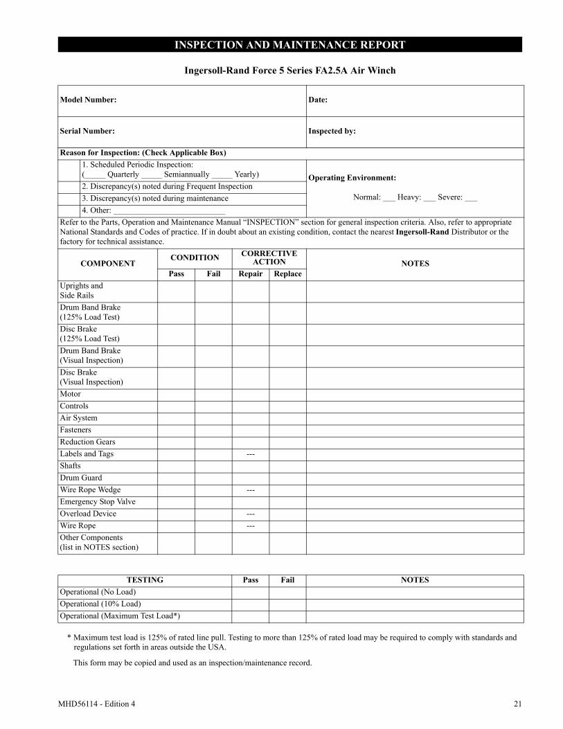
INSPECTION AND MAINTENANCE REPORT
Ingersoll-Rand Force 5 Series FA2.5A Air Winch
Model Number: Date:
Serial Number: Inspected by:
Reason for Inspection: (Check Applicable Box)1. Scheduled Periodic Inspection:(_____ Quarterly _____ Semiannually _____ Yearly) Operating Environment:
Normal: ___ Heavy: ___ Severe: ___2. Discrepancy(s) noted during Frequent Inspection3. Discrepancy(s) noted during maintenance4. Other: ___________________________
Refer to the Parts, Operation and Maintenance Manual “INSPECTION” section for general inspection criteria. Also, refer to appropriate National Standards and Codes of practice. If in doubt about an existing condition, contact the nearest Ingersoll-Rand Distributor or the factory for technical assistance.
COMPONENTCONDITION CORRECTIVE
ACTION NOTESPass Fail Repair Replace
Uprights andSide RailsDrum Band Brake(125% Load Test)Disc Brake(125% Load Test)Drum Band Brake(Visual Inspection)Disc Brake(Visual Inspection)MotorControlsAir SystemFastenersReduction GearsLabels and Tags ---ShaftsDrum GuardWire Rope Wedge ---Emergency Stop ValveOverload Device ---Wire Rope ---Other Components(list in NOTES section)
TESTING Pass Fail NOTESOperational (No Load)Operational (10% Load)Operational (Maximum Test Load*)
* Maximum test load is 125% of rated line pull. Testing to more than 125% of rated load may be required to comply with standards andregulations set forth in areas outside the USA.
This form may be copied and used as an inspection/maintenance record.
22 MHD56114 - Edition 4
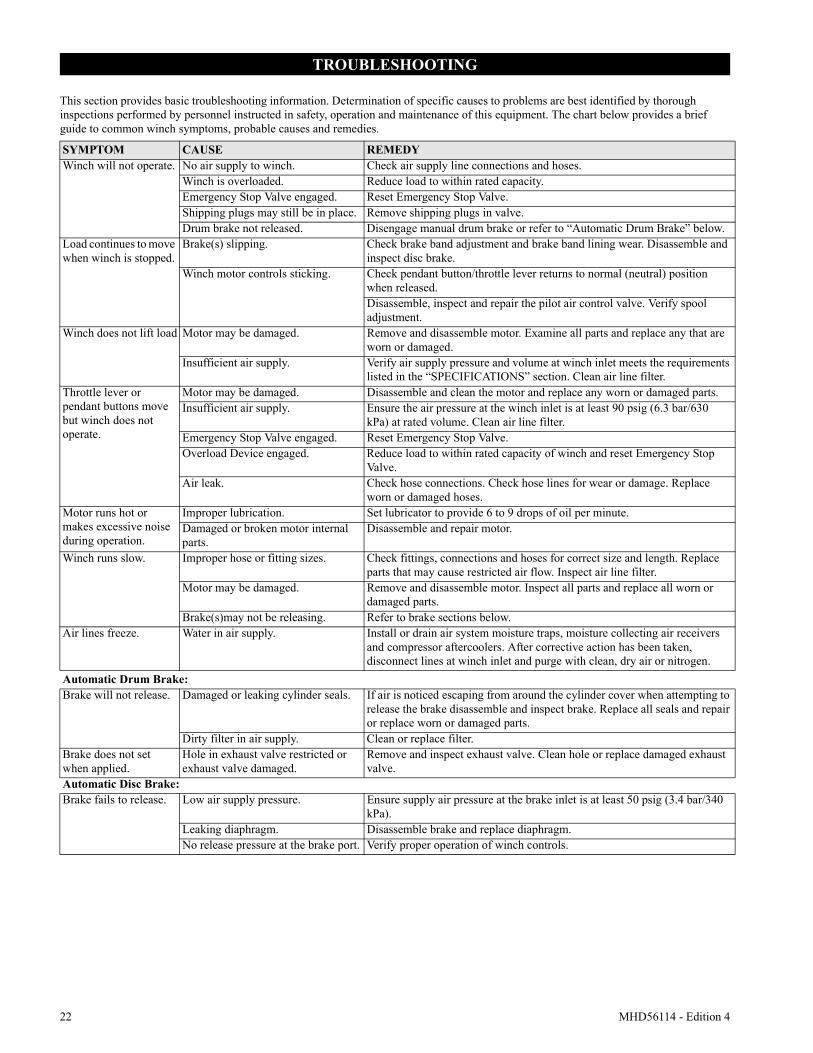
TROUBLESHOOTING
This section provides basic troubleshooting information. Determination of specific causes to problems are best identified by thorough inspections performed by personnel instructed in safety, operation and maintenance of this equipment. The chart below provides a brief guide to common winch symptoms, probable causes and remedies.
SYMPTOM CAUSE REMEDYWinch will not operate. No air supply to winch. Check air supply line connections and hoses.
Winch is overloaded. Reduce load to within rated capacity.Emergency Stop Valve engaged. Reset Emergency Stop Valve.Shipping plugs may still be in place. Remove shipping plugs in valve.Drum brake not released. Disengage manual drum brake or refer to “Automatic Drum Brake” below.
Load continues to move when winch is stopped.
Brake(s) slipping. Check brake band adjustment and brake band lining wear. Disassemble and inspect disc brake.
Winch motor controls sticking. Check pendant button/throttle lever returns to normal (neutral) position when released.Disassemble, inspect and repair the pilot air control valve. Verify spool adjustment.
Winch does not lift load Motor may be damaged. Remove and disassemble motor. Examine all parts and replace any that are worn or damaged.
Insufficient air supply. Verify air supply pressure and volume at winch inlet meets the requirements listed in the “SPECIFICATIONS” section. Clean air line filter.
Throttle lever or pendant buttons move but winch does not operate.
Motor may be damaged. Disassemble and clean the motor and replace any worn or damaged parts.Insufficient air supply. Ensure the air pressure at the winch inlet is at least 90 psig (6.3 bar/630
kPa) at rated volume. Clean air line filter.Emergency Stop Valve engaged. Reset Emergency Stop Valve.Overload Device engaged. Reduce load to within rated capacity of winch and reset Emergency Stop
Valve.Air leak. Check hose connections. Check hose lines for wear or damage. Replace
worn or damaged hoses.Motor runs hot or makes excessive noise during operation.
Improper lubrication. Set lubricator to provide 6 to 9 drops of oil per minute.Damaged or broken motor internal parts.
Disassemble and repair motor.
Winch runs slow. Improper hose or fitting sizes. Check fittings, connections and hoses for correct size and length. Replace parts that may cause restricted air flow. Inspect air line filter.
Motor may be damaged. Remove and disassemble motor. Inspect all parts and replace all worn or damaged parts.
Brake(s)may not be releasing. Refer to brake sections below.Air lines freeze. Water in air supply. Install or drain air system moisture traps, moisture collecting air receivers
and compressor aftercoolers. After corrective action has been taken, disconnect lines at winch inlet and purge with clean, dry air or nitrogen.
Automatic Drum Brake:Brake will not release. Damaged or leaking cylinder seals. If air is noticed escaping from around the cylinder cover when attempting to
release the brake disassemble and inspect brake. Replace all seals and repair or replace worn or damaged parts.
Dirty filter in air supply. Clean or replace filter.Brake does not set when applied.
Hole in exhaust valve restricted or exhaust valve damaged.
Remove and inspect exhaust valve. Clean hole or replace damaged exhaust valve.
Automatic Disc Brake:Brake fails to release. Low air supply pressure. Ensure supply air pressure at the brake inlet is at least 50 psig (3.4 bar/340
kPa).Leaking diaphragm. Disassemble brake and replace diaphragm.No release pressure at the brake port. Verify proper operation of winch controls.
MHD56114 - Edition 4 23
LUBRICATION
To ensure continued satisfactory operation of the winch, all points requiring lubrication must be serviced with correct lubricant at the proper time interval as indicated for each assembly.
Lubrication intervals recommended in this manual are based on intermittent operation of winch, eight hours each day, five days per week. If winch is operated almost continuously or more than eight hours each day, more frequent lubrication will be required. Also, lubricant types and change intervals are based on operation in an environment relatively free of dust, moisture, and corrosive fumes. Use only those lubricants recommended. Other lubricants may affect performance of winch. Approval for the use of other lubricants must be obtained from your Ingersoll-Rand distributor. Failure to observe this precaution may result in damage to the winch and its associated components.
Note: Intervals are based on winch operation in a normal environment as described in “INSPECTION” section. In ‘Heavy’ or ‘Severe’ operating conditions adjust lubrication intervals accordingly.
General Lubrication
1. Drain and replace oil in the motor, disc brake and reduction gear after the first 50 hours of initial winch operation. Thereafter, drain and replace oil according to intervals recommended.
2. Always inspect removed oil for evidence of internal damage or contamination (metal shavings, dirt, water, etc.). If indications of damage are noted, investigate and correct before returning winch to service.
3. After winch operation, allow oil to settle before topping off.4. Always collect lubricants in suitable containers and dispose
of in an environmentally safe manner.
Reduction Gear and Disc Brake Lubrication
Refer to Dwg. MHP0501 on page 24.The reduction gear and disc brake are filled and shipped with oil from the factory. Check oil level before initial winch operation.These components are splash lubricated by the oil in the housing and have no other means of lubrication. It is therefore important to use high quality Extreme Pressure (EP) rust and oxidation inhibited gear oils to ensure maximum performance and minimum down time for repairs. Oil capacity is approximately 3 quarts (2.8 litres). Oil from the reduction gear assembly also provides lubrication for the disc brake.On winches equipped with a disc brake, the reduction gear is vented through the disc brake breather plug.
Recommended Lubricant
* Units are shipped from factory with ISO VG 100 (SAE 3 EP) lubricant. Reduction Gear capacity is approximately 3 quarts (2.8 litres).
Recommended Grease
Reduction Gear and Disc Brake Fill and Drain Procedures
Refer to Dwg. MHP0501 on page 24.To Fill:1. Rotate the winch drum to align the reduction gear plugs to the
fill position. Fill plug position is at top center.2. Remove the fill plug on the reduction gear and the level plug
on the disc brake housing. Fill slowly until oil flows from the disc brake level plug hole.
3. Reinstall the plugs.
NOTICENOTICE
• Depending on ambient temperature it may take several minutes for oil to flow from the disc brake level plug hole. Wait 10 minutes after oil starts to flow from level plug hole before reinstalling plug fittings.
CAUTIONCAUTION
• Do not over fill. Excess oil will reduce operating efficiency and increase oil temperature.
The use of unsuitable oil may result in excessive temperature rise, loss of efficiency and possible damage to the gears. Use only high quality Extreme Pressure (EP) rust and oxidation inhibiting lubricant.
To Drain:1. Rotate the winch drum to align the reduction gear plugs to the
drain position. Drain plug is located at bottom center.2. Remove the reduction gear drain plug and install long pipe
nipple threaded at one end to 3/8-18 NPT. Remove drain vent plug. Remove the disc brake drain plug.
NOTICENOTICE
• Always drain oil into a suitable container and inspect drained oil for evidence of damage, metal shavings, dirt, water, etc. Dispose of oil in an environmentally safe manner.
3. Collect the drained oil and dispose of properly. If replacing oil, refer to ‘To Fill’ instructions. Reinstall the reduction gear and disc brake plugs.
INTERVAL LUBRICATION CHECKS
Start of each shift
Check flow and level of air line lubricator (approximately 6 to 9 drops per minute required at maximum motor speed).
Check winch motor oil level.
Monthly Lubricate components supplied by grease fittings.
Inspect and clean or replace air line filter.
Check reduction gear oil level.
Yearly Drain and refill winch reduction gear oil.
Drain and refill winch motor oil.
Temperature Type Oil
Below 32° F (0° C) ISO VG 68 (SAE 2 EP)
32° to 80° F (0° to 27° C) ISO VG 100 (SAE 3 EP)*
Above 80° F (27° C) ISO VG 150 (SAE 4 EP)
Temperature Type Grease
-20° to 50° F(-30° to 10° C)
EP 1 multipurposelithium based grease
30° to 120° F(-1° to 49° C)
EP 2 multipurposelithium based grease
24 MHD56114 - Edition 4
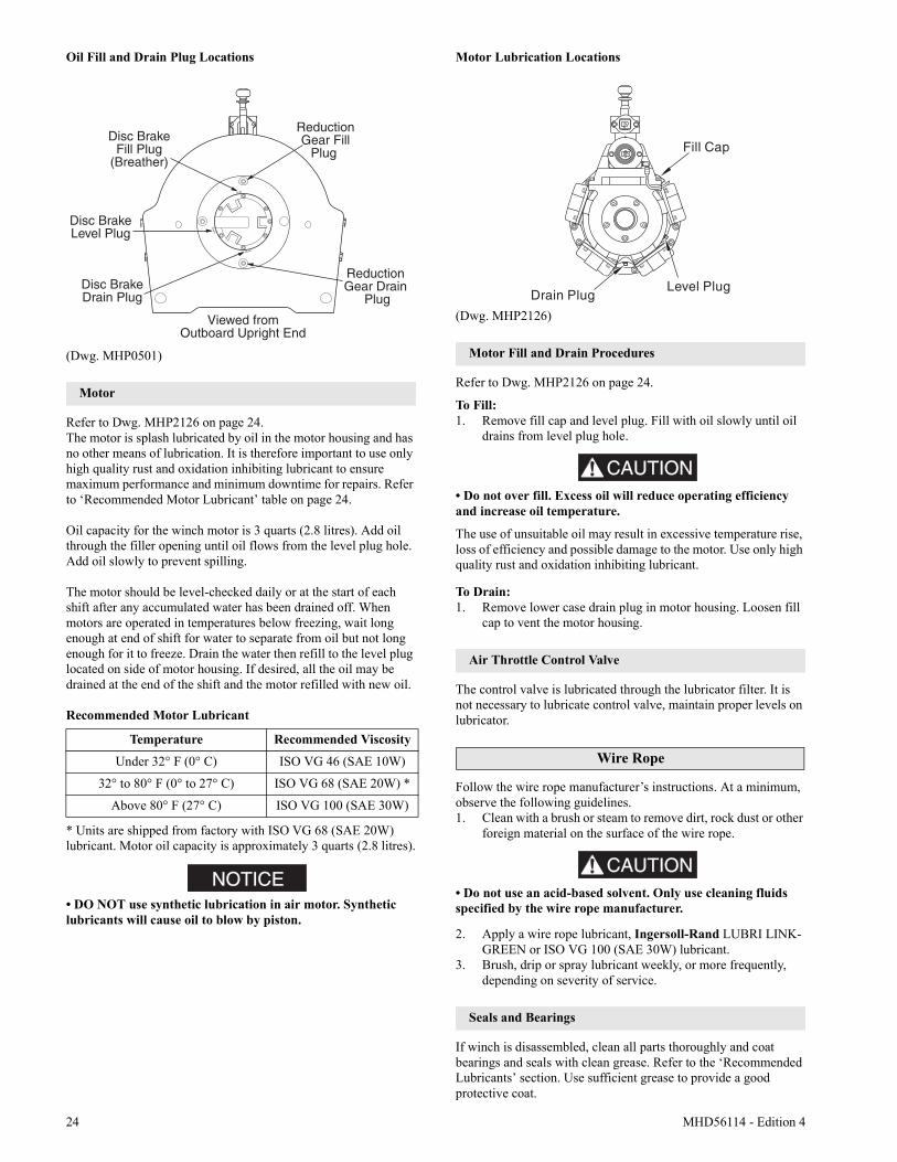
Oil Fill and Drain Plug Locations
(Dwg. MHP0501)
Motor
Refer to Dwg. MHP2126 on page 24.The motor is splash lubricated by oil in the motor housing and has no other means of lubrication. It is therefore important to use only high quality rust and oxidation inhibiting lubricant to ensure maximum performance and minimum downtime for repairs. Refer to ‘Recommended Motor Lubricant’ table on page 24.
Oil capacity for the winch motor is 3 quarts (2.8 litres). Add oil through the filler opening until oil flows from the level plug hole. Add oil slowly to prevent spilling.
The motor should be level-checked daily or at the start of each shift after any accumulated water has been drained off. When motors are operated in temperatures below freezing, wait long enough at end of shift for water to separate from oil but not long enough for it to freeze. Drain the water then refill to the level plug located on side of motor housing. If desired, all the oil may be drained at the end of the shift and the motor refilled with new oil.
Recommended Motor Lubricant
* Units are shipped from factory with ISO VG 68 (SAE 20W) lubricant. Motor oil capacity is approximately 3 quarts (2.8 litres).
NOTICE• DO NOT use synthetic lubrication in air motor. Synthetic lubricants will cause oil to blow by piston.
Motor Lubrication Locations
(Dwg. MHP2126)
Motor Fill and Drain Procedures
Refer to Dwg. MHP2126 on page 24.
To Fill:1. Remove fill cap and level plug. Fill with oil slowly until oil
drains from level plug hole.
CAUTIONCAUTION
• Do not over fill. Excess oil will reduce operating efficiency and increase oil temperature.
The use of unsuitable oil may result in excessive temperature rise, loss of efficiency and possible damage to the motor. Use only high quality rust and oxidation inhibiting lubricant.
To Drain:1. Remove lower case drain plug in motor housing. Loosen fill
cap to vent the motor housing.
Air Throttle Control Valve
The control valve is lubricated through the lubricator filter. It is not necessary to lubricate control valve, maintain proper levels on lubricator.
Wire Rope
Follow the wire rope manufacturer’s instructions. At a minimum, observe the following guidelines.1. Clean with a brush or steam to remove dirt, rock dust or other
foreign material on the surface of the wire rope.
CAUTIONCAUTION
• Do not use an acid-based solvent. Only use cleaning fluids specified by the wire rope manufacturer.
2. Apply a wire rope lubricant, Ingersoll-Rand LUBRI LINK-GREEN or ISO VG 100 (SAE 30W) lubricant.
3. Brush, drip or spray lubricant weekly, or more frequently, depending on severity of service.
Seals and Bearings
If winch is disassembled, clean all parts thoroughly and coat bearings and seals with clean grease. Refer to the ‘Recommended Lubricants’ section. Use sufficient grease to provide a good protective coat.
Temperature Recommended Viscosity
Under 32° F (0° C) ISO VG 46 (SAE 10W)
32° to 80° F (0° to 27° C) ISO VG 68 (SAE 20W) *
Above 80° F (27° C) ISO VG 100 (SAE 30W)
Disc BrakeFill Plug
(Breather)
Disc BrakeLevel Plug
Disc BrakeDrain Plug
Viewed fromOutboard Upright End
ReductionGear Fill
Plug
Reduction Gear Drain
Plug
MHD56114 - Edition 4 25
MAINTENANCE
WARNINGWARNING
• Never perform maintenance on the winch while it is supporting a load.• Before performing maintenance, tag controls:
WARNING - DO NOT OPERATE -EQUIPMENT BEING REPAIRED.
• Only allow personnel trained in safety and service on this winch to perform maintenance.• After performing any maintenance on the winch, test winch to 125% of its rated line pull at mid drum before returning to service. (Testing to more than 125% of rated line pull may be required to comply with standards and regulations set forth in areas outside the USA.)• Shut off air system and depressurize air lines before performing any maintenance.
Reduction Gear Assembly
It is recommend that the first oil change be done after approximately 50 hours initial operation. Always inspect removed oil for evidence of internal damage (metal shavings, dirt, water, etc.). Refer to the “LUBRICATION” section for recommended lubricants.
Adjustments
Disc Brake
Brake adjustment is not required. If the disc brake does not hold 100% of rated load at mid drum, disassemble and repair.
NOTICENOTICE
• Winches are provided with a breather plug located at the top of the disc brake housing. If the brake assembly is removed or repaired ensure the breather is installed and located at the top of the brake housing during reassembly.
Manual Drum Band Brake (optional feature)
Refer to Dwg. MHP1402 on page 47.1. Release wire rope tension on the drum.2. Raise handle (135) to free brake bands (136) and (137).3. Remove cotter pin (139) and pin (138).4. Rotate brake link stud (141) clockwise to increase brake
torque.5. Install pin (138) and check adjustment.
NOTICE• If brake band cannot be adjusted to hold the rated load, replace the brake band assembly.
6. Adjust brake so when brake handle locks (goes over-center), brake will hold rated load.
7. Install cotter pin (139) when adjustment is complete.8. Lift up the brake handle to free position.
Automatic Drum Band Brake (optional feature)
Refer to Dwg. MHP2508 on page 46.For adjustments, references to “clockwise” and “counterclockwise” directions, in the text, refer to directions as viewed from the head end of capscrew (120).
NOTICE• If brake band cannot be adjusted to hold rated load, replace the brake band assembly.
1. Loosen jam nut (117) closest to plunger (114).2. Adjust band assembly using capscrew (120).
a. To loosen band brake, turn capscrew (120) in the counterclockwise direction.
b. To tighten band brake, turn capscrew (120) in the clockwise direction.
NOTICE• If the capscrew (120) is not accessible, the jam nut (117) [located closest to the head of capscrew (120)] may be used to adjust the band brake. Ensure capscrew turns with nut.
3. When adjustments are complete tighten jam nut (117) closest to plunger (114).
Pilot Air Control Valve Adjustment (optional feature)
Refer to Dwg. MHP2513 on page 51.If winch operating speeds differ from performance specifications pilot air control valve may require adjustment. 1. Loosen nut (773) and adjust adjusting screw (270), located in
valve cap end (268), until drum speed for no-load haul-in equals drum speed for full load payout.
2. Rotate screw (270) ‘out’ to increase drum speed and ‘in’ to decrease drum speed. It is suggested that a chalk mark be placed on drum flange so that drum rpm can be accurately counted.
INTERVAL MAINTENANCE CHECK
Start of each shift(Operator orMaintenance Personnel)
Make a thorough visual inspection of the winch for damage. Do not operate winch if damaged.
Operate winch at low RPM in both directions. Winch must operate smoothly without sticking, binding or abnormal noises. Check operation of the brake(s).
3 Months (Maintenance Personnel)
Inspect drum brake friction linings. Clean or replace parts as required. Adjust drum brake as necessary.
Yearly (Maintenance Personnel)
Inspect the winch gearing, shafts and bearings for wear and damage. Repair or replace as necessary.
Check all supporting members, including foundations, fasteners, nuts, sheaves and rigging, etc. for indications of damage or wear. Repair or replace as required.
26 MHD56114 - Edition 4
Disassembly
General Disassembly Instructions
The following instructions provide the necessary information to disassemble, inspect, repair, and assemble the winch. Parts drawings are provided in the Parts Section.If a winch is being completely disassembled for any reason, follow the order of the topics as they are presented.It is recommended that all maintenance work on the winch be performed in a clean dust free work area.In the process of disassembling the winch, observe the following:1. Never disassemble the winch any further than is necessary to
accomplish the needed repair. A good part can be damaged during the course of disassembly.
2. Never use excessive force when removing parts. Tapping gently around the perimeter of a cover or housing with a soft hammer, for example, is sufficient to break the seal.
3. Do not heat a part with a flame to free it for removal, unless the part being heated is already worn or damaged beyond repair and no additional damage will occur to other parts.
In general, the winch is designed to permit easy disassembly and assembly. The use of heat or excessive force should not be required.
4. Keep the work area as clean as practical, to prevent dirt and other foreign matter from getting into bearings or other moving parts.
5. All seals, gaskets and ‘O’ rings should be discarded once they have been removed. New seals, gaskets and ‘O’ rings should be used when assembling the winch.
6. When grasping a part in a vise, always use leather-covered or copper-covered vise jaws to protect the surface of the part and help prevent distortion. This is particularly true of threaded members, machined surfaces and housings.
7. Do not remove any part which is a press fit in or on a subassembly unless the removal of that part is necessary for repairs or replacement.
8. When removing ball bearings from shafts, it is best to use a bearing puller. When removing bearings from housings, drive out the bearing with a sleeve slightly smaller than the outside diameter of the bearing. The end of the sleeve or pipe which contacts the bearing must be square. Protect bearings from dirt by keeping them wrapped in clean cloths.
Drum Guard Disassembly (optional feature)
Refer to Dwg. MHP2512 on page 62.1. Remove capscrews (592).2. Remove brackets (591) and/or (595) by sliding out of drum
guard (590).3. Carefully remove drum guard (590) from rear (drum brake
side) side rail (64). By design the drum guard attaches to the side rail using tabs. The smaller, upper tabs are visible on the top of the side rail. The longer, lower tab is located beneath the side rail edge. During removal care must be taken not to bend the tabs. To correctly remove, at the point where the drum guard and the side rail meet, push, or tap the lower portion of the drum guard in towards the winch drum (62). The direction of force should be directly away from the side rail. Do not pull ‘up’ or ‘down’ as the tabs may become deformed.
Winch Disassembly
Refer to Dwg. MHP0950 on page 40.1. Remove wire rope from the drum (62). Remove wire rope
anchor (63) and store for reassembly.2. Relieve pressure in the air lines and winch air components
by operating the winch control several times after the air supply has been turned off.
WARNING• Shut off, bleed down and disconnect the air supply line before performing any disassembly procedures.
3. Disconnect and tag the air lines.4. To drain oil refer to “LUBRICATION” section.5. Remove the fasteners securing winch to its foundation and
move the winch to a suitable work area before beginning disassembly.
WARNING• The air motor weighs approximately 260 lbs. (118 kg). Adequately support the air motor before removing the motor mounting capscrews.
6. Remove the ten capscrews (197) and lockwashers (196) securing the motor assembly to the motor adapter (71). Using a hoist to support the motor, pull the motor straight away from the winch. Refer to the ‘Motor Disassembly’ section if motor disassembly is required.
7. Remove drive shaft (61) and coupling (60).8. If equipped, disconnect the drum band brake.Manual Drum Brake:Refer to Dwg. MHP1402 on page 47.
a. Remove cotter pin (139) and pin (138).b. Loosen capscrew (130) and allow cam stop (132) to
rotate freely.c. To disassemble further, refer to ‘Manual Band Brake
Disassembly’ section.Automatic Drum Brake:Refer to Dwg. MHP2508 on page 46.
a. Remove capscrews (101), spacers (102) and (103).b. Remove and save spacer (105).c. Loosen two nuts (117).d. Remove capscrew (120) from plunger (114). Lower jam
nut (117) will not be removed, it is bonded to capscrew (120).
e. To disassemble further, refer to ‘Automatic Band Brake Disassembly’ section.
9. Remove any other externally mounted winch attachments. Refer to the applicable section for disassembly instructions.
MHD56114 - Edition 4 27
CAUTION
• There are a total of eight capscrews securing the brake cover to the brake housing. Two of these capscrews (24) hold the brake assembly together, but do not attach to the outboard upright. One capscrew attaching the brake assembly is located directly beneath the brake air line fitting connection; the other is located 180 degrees from the air fitting. The heads of these two capscrews sit deeper into the counterbores of the brake cover. Do not remove these two capscrews until the brake has been separated as an assembly from the winch and the directions in the ‘Disc Brake Disassembly’ section have been reviewed.
10. Disconnect and remove brake hose (75). Remove six capscrews (1) attaching disc brake assembly to outboard upright (26). Remove disc brake assembly by tapping around housing with a soft hammer or mallet while pulling out and away from upright in a horizontal direction. Remove dowel pin (20) and store until re-installation. To further disassemble the disc brake assembly, refer to Dwg. MHP0630 on page 44 and the ‘Disc Brake Disassembly’ section.
11. On standard winch: using a hoist to support the drum, remove side rails (64) and (65), one at a time, by removing four capscrews (66) attaching each side rail to uprights (26) and (68).
12. On Open Frame (Face) winch: To assist reassembly, record the number and location of washers (584) installed between the side rails (571) and (573) and bars (570). Using a hoist to support the drum, remove rear side rail (64) by removing four capscrews (66) attaching side rail to uprights (26) and (68). Remove front bars (570) and side rails (571) and (573) as an assembly by removing four capscrews (574) and washers (585). To separate bars from side rails, remove capscrews (572). Refer to Dwg. MHP1324 on page 60.
13. Remove the inboard (motor end) upright (68) by pulling straight away from drum (62) in a horizontal direction. Remove oil seal (29) and bearing (30) from upright. Discard oil seal. Discard bearing if inspection indicates replacement.
14. If equipped, remove the drum band brake assembly (104) or (146) by sliding over the end of the drum (62) flange. To further disassemble the drum brake, refer to the appropriate ‘Manual Drum Band Brake Disassembly’ or ‘Automatic Drum Band Brake Disassembly’ section.
15. Remove the outboard (disc brake end) upright (26) by pulling straight away from drum (62) in a horizontal direction. Remove oil seal (29) and bearing (30) from upright. Discard oil seal. Discard bearing if inspection indicates replacement.
CAUTION
• Ensure the reduction gear oil is drained before disassembly and that the drain and fill plugs are removed. When using jacking bolts, ensure the cover lifts evenly by turning bolt one full turn and then repeating on the other bolt. If cover jams, remove jacking bolts and gently tap around the cover to reseat it before starting over. Careful prying of the cover along its diameter during jacking, using a soft material wedge, to guide the cover is acceptable. Care must be taken not to scar, gouge or damage the machined finishes on the cover and the reducer housing mating surfaces during parts separation.
16. Stand drum on end with reduction gear on top. Remove reduction gear assembly from drum (62) by removing six capscrews (32) attaching end cover (33) to drum. Screw two 7/16 - 20 UNF x 1-1/2 inch capscrews into the threaded holes in cover (33). Turn both screws evenly until cover is separated from housing. Remove cover.
17. Screw two 1/2 - 13 UNC x 1-1/2 inch capscrews into the threaded holes in the reducer housing (59). Turn both screws evenly until housing is separated from drum. Attach suitable lifting eyes to the capscrews and remove housing from drum.
18. Disassembly of reduction gear is not recommended. If disassembly is necessary, refer to ‘Reduction Gear Disassembly’ section.
K5C2-X Control Valve Disassembly
Refer to Dwg. MHP2427 on page 48.
Handle Removal
If handle is not damaged it is not necessary to disassemble completely.1. Carefully pry off plug (935).2. Remove capscrew (901) and tab lock washer (909).
NOTICE• Observe spring (937) connection during disassembly. This spring is under tension and is required to return handle to neutral position.
3. Carefully pull handle assembly (930) from reverse valve (943). Remove spring (937).
Reverse Valve Removal
1. Remove capscrews (938), (925) and washers (924) from seal bracket (939). Remove seal bracket from housing. Remove and discard ‘O’ rings (941) and (942).
2. Remove capscrews (901) and washers (902) from exhaust flange (955). Remove flange from housing. Remove and discard ‘O’ ring (942).
3. Move reverse valve (943) out exhaust flange side of housing until ball (916) is visible on reverse valve. Allow ball (916) to drop out of bushing (944) and remove ball (916).
4. Remove bushing (944) out exhaust flange side of housing.
NOTICE• Dowel pin (945) allows the bushing to be removed only from the exhaust flange side of housing. Ball (916) retains reverse valve (943) in bushing (944).• Do not remove reverse valve (943), bushing (944) and ball (916) at the same time, damage may occur to bushing.• Take care to not allow ball (916) to drop in motor. If this occurs it may be necessary to disassemble motor to retrieve ball (916).
Piston Removal
1. Remove capscrews (901) and washers (902) from piston cover (919). Remove cover and discard gasket (918).
2. Remove capscrews (901) and washers (902) from poppet cover (903). Remove cover and discard gasket (904).
28 MHD56114 - Edition 4
3. Remove the following items from housing poppet bore: spring (905), poppet cap (906) and poppet seal (907).
4. From poppet side, push piston (922) out of housing. Remove ‘O’ rings (921) and (923) and discard.
Pilot Valve Removal
NOTICE• For easier removal it is recommended to use I-R pilot seat tool (920). This must be purchased separately. Operation of this tool (920) is similar to an allen wrench or screw driver.
If pilot valve is not damaged it is not necessary to disassemble completely.1. Remove plug (912).2. Remove pilot valve assembly (910) as an assembly.3. Discard and replace pilot valve assembly (910) if necessary.
K5C2-EX Control Valve Disassembly
Refer to Dwg. MHP2434 on page 54.
Handle Removal
Follow disassembly instructions for K5C2-X Control Valve.
Reverse Valve Removal
1. Remove capscrews (938), (925) and washers (924) from seal bracket (939). Remove seal bracket from housing. Remove and discard ‘O’ rings (941) and (942).
2. Remove capscrews (721) and washers (902) from exhaust flange (955) and exhaust adapter (723). Remove and discard ‘O’ rings (942) and (722).
3. Move reverse valve (943) out exhaust flange side of housing until ball (916) is visible on reverse valve. Allow ball (916) to drop out of bushing (944) and remove ball (916).
4. Remove bushing (944) out exhaust flange side of housing.
NOTICE• Dowel pin (945) allows the bushing to be removed only from the exhaust flange side of housing. Ball (916) retains reverse valve (943) in bushing (944).• Do not remove reverse valve (943), bushing (944) and ball (916) at the same time, damage may occur to bushing.
Piston Removal
Follow disassembly instructions for K5C2-X Control Valve.
Pilot Valve Removal
Follow disassembly instructions for K5C2-X Control Valve.
Emergency Stop Removal
1. Remove adapter (706) and E-Stop button (705).2. Remove plunger (707). Remove and discard ‘O’ rings (703).3. Pull spring (711) out of valve housing and discard.
Overload Valve Removal
1. Remove cap (700). Remove and discard grommet (701).2. Pull out plunger (702), remove and discard ‘O’ rings (703).3. Remove capscrews (901) and washers (902) from cover
(719) underneath valve housing.
NOTICE• Cover (719) retains spring (718). To remove capscrews (901) and washer (902) unscrew in a crisscross pattern.
4. Remove adjusting screw (720).5. Remove and discard ‘O’ ring (716), gasket (714) and ‘O’
ring (713) from piston.6. Do not remove seal from piston, if piston appears damaged
or worn replace.
Motor Disassembly
Refer to Dwg. MHP0690 on page 42.1. Remove the five capscrews (255) from the exhaust flange
(254).2. Remove the rotary valve housing (247) by pulling it out of
the motor housing (217) as an assembly with the exhaust flange (254).
3. Remove rotary valve (250) by pulling it out from the assembly through the motor end of the rotary valve housing (247).
4. Remove exhaust flange (254) from rotary valve housing (247) by gently tapping edges of flange with a soft hammer until seal is loosened.
5. Remove mounting flange (216) from motor by pulling straight away from motor.
6. Remove each cylinder head (201) by removing the four capscrews (200). Remove head gaskets (209) and discard.
7. Pull the cylinder liner (208) straight out.8. Position the piston (204) at the top of its stroke. In this
position, with the cylinder liner pulled out in step 7, the wrist pin (203) can be removed. Remove one retainer ring (205) from either side of piston (204). Push the wrist pin (203) out by hand from one side. If the wrist pin is too tight it is acceptable to carefully heat the piston to 200° F (93° C) or less and then push the wrist pin out.
NOTICE• If original piston, wrist pin, connecting rod or cylinder liner are to be reassembled, number each set. Also add radial alignment marks for each piston and cylinder liner to the motor housing.
9. Remove the remaining cylinder liners and pistons as described in steps 7 and 8. To remove the crank assembly, all pistons and cylinder liners must be removed.
10. Crank assembly (231) can now be removed with the oil slinger (230) by pulling straight out from the motor housing (217). Use care while guiding the connecting rods (206) through the inside of the motor housing.
Crankshaft Disassembly
1. Remove cotter pin (236) and the pin nut (237).2. Remove lock pin (235) by carefully driving it out of its
location. Use care not to damage the threads.
MHD56114 - Edition 4 29
3. Pull the crankshaft valve end (231) off the crankshaft.4. Remove connecting rod rings (234), connecting rod bushing
(233), sleeve (232) and connecting rods (206). Record the five connecting rod (206) numbers and foot directions so they can be re-installed in the same order.
5. Oil slinger (230) does not have to be removed unless damaged. If removal is required, heating of the five screws (229) may be necessary to loosen the Loctite® connection.
Disc Brake Disassembly
Refer to Dwg. MHP0630 on page 44.
NOTICE• Prior to disassembly, matchmark the cover (2), housing (6) and support plate (19) to assist in proper alignment of parts during reassembly.
1. Remove brake shaft (25) and retainer ring (23). Place brake assembly on a flat surface with cover (2) on top. Remove elbow fitting (80) and exhaust valve (79). Alternately and evenly loosen the two capscrews (24) until the brake spring (17) compression has been relaxed. Remove capscrews.
2. Remove cover (2) and diaphragm (3).3. Using a small tipped screwdriver or similar tool, remove ring
(4). Remove diaphragm support (5).4. Remove housing (6) by lifting straight away from brake
parts. Collect the three dowel pins (9) and store until reinstallation. Inspect pins for deformation, wear and damage. Replace if parts fail inspection.
5. Alternately remove the six separator plates (14) and five friction plates (13).
6. Remove the pressure plate (15) and springs (17).7. Grasp the outer race (12) and remove the sprag clutch as an
assembly. Remove the spacer (11) between the sprag clutch assembly and support plate (19).
8. Remove gasket (18) from support plate (19). Discard gasket.9. To remove the bearing (21) from the support plate (19) first
remove the retainer ring (22) and then press the bearing out of the support plate recess.
NOTICE• To prevent accidental damage, remove the bearing (21) only if it requires replacement.
10. Separate the sprag clutch assembly into its component parts. The sprag clutch assembly consists of the inner race (10), two spacers (11), the outer race (12) and the sprag clutch (16). The sprag clutch can be further disassembled into two wearing plates and the sprag cage.
Automatic Drum Band Brake Disassembly
Optional feature. Refer to Dwg. MHP2508 on page 46.1. Loosen jam nut (117) closest to plunger (114). Turn
capscrew (120) counterclockwise until disconnected from plunger.
2. Disconnect air line from brake cylinder (121). With the aid of a strap wrench, remove brake cylinder (121) and components as an assembly by turning brake cylinder counterclockwise until disconnected from brake bracket (106).
3. Disconnect brake bracket (106) from band assembly by removing three capscrews (101), spacers (102) and spacer tubes (103). Remove spacer plate (105).
4. Disconnect brake bracket from motor end upright (68) by removing two capscrews (107) and two capscrews (112).
DANGER•
• Springs (124) and (127) exert a considerable force on cover (125). Extreme care must be taken when disassembling the cylinder assembly and removing cover (125).
5. To disassemble the cylinder (121) assembly into its component parts conduct the following:a. Use a press to compress the cover (125) enough to
remove retainer ring (126). Slowly, and carefully, relax the load exerted on cover (125) by the springs (124) and (127). Remove cover and springs.
b. Remove washer (128).c. Remove piston (123) assembly.d. Disassemble piston assembly into component parts by
removing retainer ring (111) and separating cylinder rod (108) from piston (123). Remove ‘O’ rings (122), (109) and (110). Discard ‘O’ rings.
6. Remove plunger (114) assembly and spring (113) from brake bracket (106).
Manual Drum Band Brake Disassembly
Optional feature. Refer to Dwg. MHP1402 on page 47.The winch does not have to be removed or disassembled to disassemble the manual band brake.
CAUTION
• Release wire rope tension on the drum and disconnect main air supply line.
1. Raise handle (135) to free brake bands (136) and (137).2. Remove cotter pin (139) and pin (138).3. Rotate brake link stud (141) counter-clockwise until free
from brake handle.4. Remove grip from brake handle (135). Loosen screws in
brake handle until handle can be freed from brake band bracket, remove brake handle. Remove pivot nut (134).
5. Remove cotter pin (144) and washer (142).6. Loosen capscrews (133).7. Spread brake band (137) apart slightly and slide out over
drum flange. Rotate brake band around drum and remove. 8. Repeat this procedure for brake band (136).9. Remove capscrews (133), washers (131), and adapter plate
(145).10. Press bushings (143) out of brake band pivot brackets
.
Reduction Gear Disassembly
NOTICE• It is not recommended to disassemble reduction gear.
Refer to Dwg. MHP0950 on page 40.1. Place the reduction gear assembly on a clean work bench
such that reducer housing (48) with oil seal (58) is down.2. Remove capscrews (33) and cover (34) from housing (38).
30 MHD56114 - Edition 4
3. Remove thrust washer (35) and output carrier assembly (36).4. Remove the input carrier assembly (42) by grasping the
intermediate sun gear (39) and removing as an assembly. This also removes the input sun gear (43). Ensure that thrust bearing (45) and thrust washers (44), located on the end of the input sun gear (43), are removed.
NOTICE• Do not disassemble carrier assemblies (36) and (42). Replace if damaged or worn.
5. Remove the oil seal (58) and discard. Remove the caged needle bearing (46) only if replacing. To remove press bearing out of housing.
Free Spool Disassembly
Refer to Dwg. MHP2414 on page 63.1. Relieve pressure in the air lines and winch air components by
operating the winch control several times after the air supply has been turned off.
WARNING• Shut off, bleed down and disconnect the air supply line before performing any disassembly procedures.• Do not attempt repairs with load on wire rope.
2. To assist in reassembly, place match marks on the housing (502) and outboard upright (26).
3. Remove free spool shifter assembly (507) by pulling it out of housing (502). This assembly is held in place by ‘O’ ring (501). Remove and discard ‘O’ ring (501).
4. Pin (508) and handle (512) are held in position by Loctite® applied during assembly. To remove these parts, carefully heat the shifter (515) until parts are removable.
5. Remove capscrew and washers (902). Remove cover (2) and gasket (18). Discard gasket.
6. Remove capscrews (505) and carefully pull housing (502) away from outboard upright (26).
7. Remove output shaft (28) from drum (62).
Two Lever Pendant Disassembly
Refer to Dwg. MHP2346 or MHP1677 on page 52.1. Remove fittings (455) and lifting eye (440).2. Unscrew plugs (444). Remove springs (445) and balls (446).3. Tap out pin (447) and remove levers (453).4. Remove setscrew (450) from pendant handle (454).5. Remove valve assemblies (452). Remove ‘O’ rings (443)
and (449). Discard ‘O’ rings.6. Remove plug (470) or emergency stop valve (441) from
pendant handle.7. Remove retainer ring (458) and exhaust washer (457).
Cleaning, Inspection and Repair
Cleaning
Clean all winch component parts in solvent (except the drum brake bands and disc brake friction plates). The use of a stiff bristle brush will facilitate the removal of accumulated dirt and sediments on the housings, frame and drum. If bushings have been removed it may be necessary to carefully remove old Loctite® from the bushing bores. Dry each part using low pressure, filtered compressed air. Clean the drum brake band using a wire brush or emery cloth. Do not wash the drum brake band in solvent. If the drum brake band lining is oil soaked, it must be replaced.
Inspection
All disassembled parts should be inspected to determine their fitness for continued use. Pay particular attention to the following:1. Inspect all gears for worn, cracked, or broken teeth.2. Inspect all bushings for wear, scoring, or galling.3. Inspect shafts for ridges caused by wear. If ridges caused by
wear are apparent on shafts, replace the shaft. 4. Inspect all threaded items and replace those having
damaged threads.5. Inspect the drum band brake lining for oil, grease and
glazing. If the drum band brake lining is oil-soaked, excessively greasy or overly glazed replace the brake band. Remove small glazed areas of band brake lining by sanding lightly with a fine grit emery cloth.
6. Measure the thickness of the drum band brake lining. If the drum brake band lining is less than 0.062 in. (2 mm) thick anywhere along the edges replace the brake band assembly.
7. Inspect motor cylinder (208) bores for signs of wear. Cylinders can be lightly honed, for any large scratches or wear patterns, replace cylinder assembly.
Repair
Actual repairs are limited to the removal of small burrs and other minor surface imperfections from gears, shafts, housings and machined surfaces. Use a fine stone or emery cloth for this work. 1. Worn or damaged parts must be replaced. Refer to the
applicable parts listing for specific replacement parts information.
2. Inspect all remaining parts for evidence of damage. Replace or repair any part which is in questionable condition. The cost of the part is often minor in comparison with the cost of redoing the job.
3. Smooth out all nicks, burrs, or galled spots on shafts, bores, pins, or bushings.
4. Examine all gear teeth carefully, and remove nicks or burrs.5. Polish the edges of all shaft shoulders to remove small nicks
which may have been caused during handling.6. Remove all nicks and burrs caused by lockwashers.
Assembly
General instructions• use all new gaskets and seals.• replace worn parts.• assemble parts using match marks applied during
disassembly. Compare replacement parts with originals to identify installation alignments.
• lubricate all internal parts with rust and oxidation inhibiting lubricant, ISO VG 100 (SAE 30W).
MHD56114 - Edition 4 31
Motor Assembly
Refer to Dwg. MHP0690 on page 42.1. Install two seal rings (251) on each end of rotary valve (250).
Place bearing (252) onto the rear of rotary valve (250) and press into position. Press only on the bearing inner race. With the rotary valve housing (247) exhaust flange side down, install rotary valve into housing.
2. Install ‘O’ ring (244) into motor housing (217).3. Install the rotary valve housing gasket (243) onto rotary
valve housing (247). With the exhaust flange down on the bench, install motor housing (217) onto rotary valve housing (247). Check for any evidence of damage to ‘O’ ring (244) when the rotary valve housing is fully engaged. Install exhaust flange (254) and tighten capscrews (255) to 50 ft lbs (68 Nm).
4. If removed, press crank bearing (228) on crank assembly (231). Press only on the inner race of the bearing.
5. Place crank assembly (231) on a work bench with the oil slinger (230) down and slide the sleeve (232), with tang up, on the crankpin.
6. Slide connecting rod bushing (233) over the sleeve (232) and first connecting rod ring (234) with the chamfer up.
7. Install the connecting rods (206) in the same order as removed, with all feet pointing in the same direction, using the first connecting rod ring (234) to hold one side of the connecting rod feet.
8. Slide the second connecting rod ring (234) over the other side of the connecting rod feet with the chamfer on the ring facing down (toward the stem of the connecting rod).
9. Slide the crank shaft valve end over the crank pin while simultaneously aligning the tang on the sleeve (232) with the slot in the crank shaft.
10. Rotate and position the crank shaft valve end relative to the crank pin to allow installation of the lock pin (235).
11. Tap the lock pin (235) into place and install the pin nut (237). Torque nut to 60 ft lbs (81 Nm).
12. Install cotter pin (236).13. Install roll pin (240) and bearing (228) into the valve end of
the crank shaft.14. Check that all connecting rods move freely around the crank.
Position the crank assembly (231) into the motor housing (217). Ensure the bearing (228) is seated and connecting rods (206) are centered in the cylinder holes.
NOTICE• Make certain that the roll pin (240) and the three lugs on the rotary valve (250) line up with the corresponding hole and lugs on the crank shaft.• Do not allow the rotary valve (250) to slide back in rotary valve housing (247). If the rotary valve slides in too far, the rotary valve and crankshaft will not align properly and will restrict further assembly.
15. Rotate the crank assembly until one connecting rod (206) is at the top of its stroke. Install a piston (204) with its rings (202 and 207) to the connecting rod (206) with wrist pin (203) and retainer rings (205).
16. Install a new cylinder head gasket (209) before installing the cylinder liner (208).
17. Install the cylinder liner (208) over the piston (204) by compressing both piston rings (202) and (207) with a single band ring compressor.
18. Install cylinder head (201) over the cylinder and secure cylinder head to motor housing (217) with four capscrews (200). Torque capscrews to 60 ft lbs (81 Nm).
19. Repeat Steps 15 through 18 with the remaining cylinders.
NOTICE• When installing the two lowest cylinder heads (201), use seal washers on capscrews (200).
20. Rotate motor by hand. Motor should rotate without binding.21. Press oil seal (227) into inside of mounting flange (216).22. Install mounting flange (216) and gasket (226) on the front
of the motor housing (217). Make sure notches on both parts are aligned.
23. Lightly lubricate ‘O’ ring (70) and install in groove on motor adapter (71).
24. Install eye bolts (213), vent cap assembly (210) and pipe plug (218) in the motor housing (217). From the rotary valve housing end of the motor, ensure plug (218) is installed in the left oil fill hole of the motor.
25. Install motor on winch at motor adapter (71) using capscrews (197), lockwashers (196) and washers (198).
26. Ensure oil drain (225) and level plug (225) are installed.
K5C2-X Control Valve Assembly
Refer to Dwg. MHP2427 on page 48.
Reverse Valve Assembly
1. Insert reverse valve (943) into bushing (944) with ball slot oriented UP, approximately 2-1/2 in. (64 mm).
2. Insert bushing (944) and reverse valve (943) into valve housing (917) from exhaust flange side, ensuring that groove in bushing is aligned with pin (945).
3. Insert ball (916) onto reverse valve platform. With finger, push ball (916) in housing until ball hits end of reverse valve.
4. Holding ball (916) in position on reverse valve platform, rotate reverse valve from neutral position to approximately 45 degrees in either direction. Ball will ‘walk’ up side of reverse valve platform and move in ball hole in bushing.
NOTICE• Do not rotate reverse valve past a 90 degree position, it may result in the ball (916) falling in motor.
5. Slowly push reverse valve, while still in the 45 degree position, the rest of the way in housing until flush with surface. From other side of valve rotate reverse valve back to neutral position, ball should be seated in ball slot at that time.
6. Lubricate ‘O’ ring (942) and place it in groove in exhaust flange (955).
7. Secure exhaust flange (955) to valve housing with capscrews (901) and washers (902).
8. Insert ‘O’ ring (941) into seal bracket (939). Lubricate ‘O’ ring (942) and place into groove in seal bracket.
9. Place seal bracket over end of reverse valve. Using finger pressure, press until seal is seated on reverse valve and seal bracket is seated on valve housing. Secure with washers (924) and capscrews (925) and (938).
32 MHD56114 - Edition 4
Pilot Valve Assembly
NOTICE• For easier installation it is recommended to use I-R pilot seat tool (920). This must be purchased separately. Operation of this tool (920) is similar to an allen wrench or screw driver.
1. Install pilot valve assembly (910).2. Apply thread sealant Loctite 545 ® to pilot seat (914), place
pilot valve assembly into valve housing. Use a large flat tipped screw driver to engage slots in pilot seat and tighten until pilot assembly is 1/8 in. (3.175 mm) from housing bore.
3. Insert plug (912) and tighten.
Piston Assembly
1. Lubricate and install ‘O’ rings (921) and (923) on piston (922).
2. Insert assembled piston into valve housing (917) from handle side.
3. Secure with gasket (918), piston cover (919), washers (902) and capscrews (901).
4. Place poppet seal (907) into poppet cap (906). Place this assembly into valve housing and seat on piston (922).
5. Place spring (905) over this assembly.6. Secure with gasket (904), poppet cover (903), washers (902)
and capscrews (901).
Handle Assembly
1. Place spring (937) over reverse valve handle end in seal bracket.
NOTICE• Spring (937) will have to be ‘Cocked’ over stud in seal bracket. This will ensure handle returns to neutral.
2. Place handle assembly over reverse valve end. Slide handle will have to be lifted slightly to allow pin to fit into slot in seal bracket.
3. Secure handle assembly (930) to reverse valve with tab lock washer (909) and capscrew (901), torque to 15 ft. lbs. (21 Nm). Washer (909) has small tab on side, engage with small hole in handle.
4. Bend tabs of washer (909) over flats of capscrew.5. Press plug (935) into handle assembly to cover capscrew.
Check control handle movement. Correct any discrepancies.
K5C2-EX Control Valve Assembly
Refer to Dwg. MHP2434 on page 54.
Reverse Valve Assembly
1. Insert reverse valve (943) into bushing (944) with ball slot oriented UP. Apply grease to ball (916) and insert into ball slot of reverse valve (943) through bushing (944).
2. Insert bushing (944), reverse valve (943) and ball (916) into valve housing (917) from exhaust flange side, ensuring that groove in bushing is aligned with pin (945).
3. Lubricate ‘O’ rings (942) and (722), and place in grooves in exhaust adapter (723).
4. Lubricate ‘O’ rings (942) and place in grooves in exhaust flange (955).
5. Secure exhaust adapter with exhaust flange to valve housing with capscrews (721) and washers (902).
6. Insert ‘O’ ring (941) into seal bracket (939). Lubricate ‘O’ ring (942) and place into groove in seal bracket.
7. Place seal bracket over end of reverse valve. Using finger pressure, press until seal is seated on reverse valve and seal bracket is seated on valve housing. Secure with washers (924) and capscrews (925) and (938).
Pilot Valve Assembly
Follow assembly instructions for K5C2-X Control Valve.
Piston Assembly
Follow assembly instructions for K5C2-X Control Valve.
Handle Assembly
Follow assembly instructions for K5C2-X Control Valve.
Emergency Stop Assembly
1. Insert spring (711) into valve housing (917).2. Place ‘O’ rings (703) on plunger (707).3. Insert plunger into valve housing.4. Screw adapter (706) and E-Stop button (705) into valve
housing.5. Tighten adapter until snug, do not over tighten.
Overload Valve Assembly
1. Replace ‘O’ rings (703) on plunger (702).2. Insert plunger (702) with ‘O’ rings in valve housing (917).3. Replace grommet (701) in cap (700).4. Install and tighten cap (700) flush to valve housing.5. Replace piston (712) if appears damaged or worn.6. Insert ‘O’ ring (713) on piston (712).7. Replace gasket (714).
NOTICE• Cover (719) retains springs (718), adjustment nut (717) and plate (715). Insert capscrews (902) and washers (901) in a crisscross patter until tightened evenly.
8. Insert adjusting screw (720), refer to ‘OPERATION’ section for overload valve adjustment.
Reduction Gear Assembly
Refer to Dwg. MHP0950 on page 40.1. Install oil seal (58) in housing (48).2. Install needle bearing (46) if removed during disassembly.3. Install thrust washers (44) on input sun gear (43).4. Install input sun gear assembly (43) in housing (48).5. Install (40) on either side of input gear carrier (42).6. Install input gear carrier (42) on input sun gear (43).7. Align intermediate sun gear (39) with input gear carrier (42)
and install in gear carrier (42). Take care not to damage teeth on either part while installing.
MHD56114 - Edition 4 33
8. Install thrust washer (35) and output gear carrier (36) in housing (48). Align with intermediate sun gear (39). Take care not to damage teeth on either part while installing.
9. Align holes in cover (34) with housing (48) and secure with capscrews (33). Torque to 60 ft lbs (81 Nm).
10. With drum standing on end, place reduction gear assembly into drum. Place Loctite® 515 on mating surfaces of housing (87) and end cover. Align the 3/8 inch NPT holes in the end cover with counterbore marks on the housing mating flange. Secure in place by evenly installing sixteen capscrews (33). Torque capscrews to 60 ft lbs. (81 Nm).
11. Cover the reduction gear to prevent dirt and contaminants from entering assembly and place in a safe place until ready for assembly to winch uprights.
Winch Assembly
Refer to Dwg. MHP0950 on page 40.
NOTICE• Unless otherwise stated capscrew torque values listed are for lubricated or plated threads. This assembly uses “blue bolts” in numerous locations. These are plated and should not be lubricated.
1. Using a hoist, support the drum.2. Install bearing (30) in inboard (motor end) upright (68).
With oil seal (29) lip facing towards the motor, install oil seal in inboard upright.
3. Install output shaft (28), bearing (30) and oil seal (29) in outboard upright (26). Oil seal lip must face toward the brake. Install the outboard upright onto drum by aligning splines of output shaft to reduction gear output carrier assembly splines.
4. If equipped with automatic drum brake, install the drum band brake bracket and piston assemblies. Do not attach the brake band assembly (104). Refer to the ‘Drum Band Brake’ section for instructions.
5. Install coupling (60) on drive shaft (61) and install on end of the input sun gear (54), located in the reduction gear assembly.
6. If equipped with automatic drum brake, place brake band assembly (104) onto drum brake flange. Place inboard (motor end) upright (68) on drum.
7. For standard winch: loosely attach the side rails (64) and (65) to the uprights (26) and (68) using four capscrews (66) for each side rail. Tighten capscrews and torque to 75 ft lbs (102 Nm) for dry threads, or 55 ft lbs (75 Nm) if thread lubrication is used.
8. For Open Frame (Face) winch: Refer to Dwg. MHP1324 on page 60. Loosely attach the rear side rail (64), using four capscrews (66) to uprights (26) and (68). a. If noted during disassembly, place washers (584), in
quantities and locations recorded, and bars (570) between side rails (571) and (573). Secure using capscrews (572) and torque to 150-175 ft lbs (203-237 Nm). Go to step 8.c.
b. If washer (584) locations and quantities were not recorded, loosely attach side rail (571) to upright (26) and side rail (573) to upright (68) using capscrews (574). Using washers and bars (570), determine the correct arrangement of washers required to ensure side rails are even with drum (62) flange edge. The washers (584) must be evenly distributed with an equal number
located on each end of the bars. Once quantities are determined, remove the side rails and reassembly as described in step 8.a.
c. Place open frame assembly onto uprights (26) and (68). Ensure side rail (571) is located on upright (26) and side rail (573) is located on upright (68). Place washers (585) on capscrews (574) and secure frame assembly to uprights. Torque capscrews to 75 ft lbs (102 Nm).
d. Secure rear side rail (64) to uprights, torque capscrews (66) to 75 ft lbs (102 Nm).
9. Align holes in motor adapter (71) and install on upright. Secure with six capscrews (73). Torque capscrews to 125 ft lbs (170 Nm) for dry threads, or 95 ft lbs (129 Nm) if thread lubrication is used.
10. If equipped, attach band brake assembly (104) as described in the ‘Drum Band Brake Assembly’ section.
Disc Brake Assembly
Refer to Dwg. MHP0630 on page 44.1. Install bearing (21) into support plate (19) and secure with
retainer ring (22).2. In this order, place spacer (11), sprag clutch (16), outer race
(12) and spacer (11) on inner race (10). Test sprag clutch operation. Refer to Dwg. MHP0667 on page 34.
NOTICE• Correct sprag clutch installation prevents clockwise rotation (brake engages) and allows counterclockwise rotation when viewed from the end cover (2) end of the brake assembly.
WARNING• Incorrect assembly of the sprag clutch will adversely affect winch operation. In haul-in operation, sprag clutch will be engaged resulting in restricted winch operation. In neutral and payout positions, the sprag clutch can rotate resulting in brake not holding load. Ensure the sprag clutch is correctly installed.
3. Install assembly on support plate (19). 4. Install twelve springs (17) in holes on inside of support plate
(19).5. Install gasket (18) and pressure plate (15).6. Determine correct alignment of end cover (2), housing (6)
and support plate (19) by checking matchmarks placed during disassembly, or by placing housing on support plate and matching capscrew holes.
7. Correctly align with dowel slots on the housing (6) and install six separator plates (14) and five friction plates (13) in the following order:a. Begin with a separator plate, followed by a friction
plate. Alternate plates. Refer to Dwg. MHP1011on page 34.
WARNINGFailure to correctly arrange friction and separator plates will result in erratic brake operation. Sudden brake applications may cause winch and/or wire rope damage resulting in a falling load.
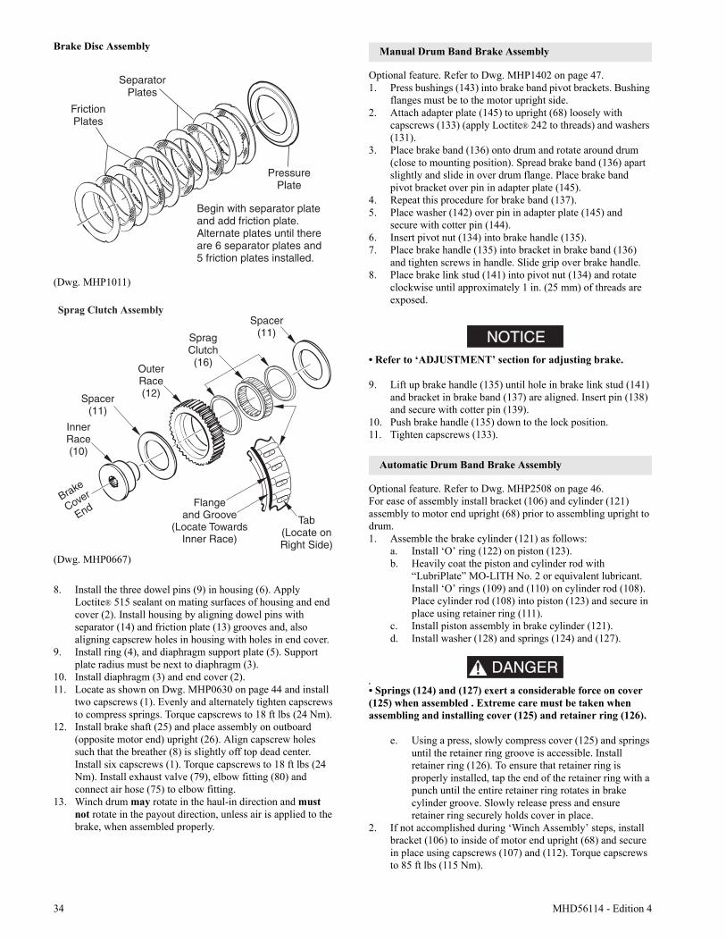
34 MHD56114 - Edition 4
Brake Disc Assembly
(Dwg. MHP1011)
(Dwg. MHP0667)
8. Install the three dowel pins (9) in housing (6). Apply Loctite® 515 sealant on mating surfaces of housing and end cover (2). Install housing by aligning dowel pins with separator (14) and friction plate (13) grooves and, also aligning capscrew holes in housing with holes in end cover.
9. Install ring (4), and diaphragm support plate (5). Support plate radius must be next to diaphragm (3).
10. Install diaphragm (3) and end cover (2).11. Locate as shown on Dwg. MHP0630 on page 44 and install
two capscrews (1). Evenly and alternately tighten capscrews to compress springs. Torque capscrews to 18 ft lbs (24 Nm).
12. Install brake shaft (25) and place assembly on outboard (opposite motor end) upright (26). Align capscrew holes such that the breather (8) is slightly off top dead center. Install six capscrews (1). Torque capscrews to 18 ft lbs (24 Nm). Install exhaust valve (79), elbow fitting (80) and connect air hose (75) to elbow fitting.
13. Winch drum may rotate in the haul-in direction and must not rotate in the payout direction, unless air is applied to the brake, when assembled properly.
Manual Drum Band Brake Assembly
Optional feature. Refer to Dwg. MHP1402 on page 47.1. Press bushings (143) into brake band pivot brackets. Bushing
flanges must be to the motor upright side.2. Attach adapter plate (145) to upright (68) loosely with
capscrews (133) (apply Loctite® 242 to threads) and washers (131).
3. Place brake band (136) onto drum and rotate around drum (close to mounting position). Spread brake band (136) apart slightly and slide in over drum flange. Place brake band pivot bracket over pin in adapter plate (145).
4. Repeat this procedure for brake band (137).5. Place washer (142) over pin in adapter plate (145) and
secure with cotter pin (144).6. Insert pivot nut (134) into brake handle (135).7. Place brake handle (135) into bracket in brake band (136)
and tighten screws in handle. Slide grip over brake handle.8. Place brake link stud (141) into pivot nut (134) and rotate
clockwise until approximately 1 in. (25 mm) of threads are exposed.
NOTICE• Refer to ‘ADJUSTMENT’ section for adjusting brake.
9. Lift up brake handle (135) until hole in brake link stud (141) and bracket in brake band (137) are aligned. Insert pin (138) and secure with cotter pin (139).
10. Push brake handle (135) down to the lock position.11. Tighten capscrews (133).
Automatic Drum Band Brake Assembly
Optional feature. Refer to Dwg. MHP2508 on page 46.For ease of assembly install bracket (106) and cylinder (121) assembly to motor end upright (68) prior to assembling upright to drum.1. Assemble the brake cylinder (121) as follows:
a. Install ‘O’ ring (122) on piston (123).b. Heavily coat the piston and cylinder rod with
“LubriPlate” MO-LITH No. 2 or equivalent lubricant. Install ‘O’ rings (109) and (110) on cylinder rod (108). Place cylinder rod (108) into piston (123) and secure in place using retainer ring (111).
c. Install piston assembly in brake cylinder (121).d. Install washer (128) and springs (124) and (127).
DANGER•
• Springs (124) and (127) exert a considerable force on cover (125) when assembled . Extreme care must be taken when assembling and installing cover (125) and retainer ring (126).
e. Using a press, slowly compress cover (125) and springs until the retainer ring groove is accessible. Install retainer ring (126). To ensure that retainer ring is properly installed, tap the end of the retainer ring with a punch until the entire retainer ring rotates in brake cylinder groove. Slowly release press and ensure retainer ring securely holds cover in place.
2. If not accomplished during ‘Winch Assembly’ steps, install bracket (106) to inside of motor end upright (68) and secure in place using capscrews (107) and (112). Torque capscrews to 85 ft lbs (115 Nm).
MHD56114 - Edition 4 35
3. Assemble roller (116) in plunger (114) and secure using dowel pin (115). Heavily coat the plunger assembly with “LubriPlate” MO-LITH No. 2 or equivalent lubricant. Install spring (113) and plunger assembly in brake bracket (106). Align groove in plunger towards hole in motor end (68) upright.
4. Align cylinder rod roller surface to groove in plunger. Turn cylinder (121) clockwise until snug. Adjust cylinder (121) such that the air hose connection port is horizontal and towards the motor.
Conduct the following when the winch is assembled, but prior to mounting to the foundation. The motor end of the winch should be raised enough to allow access to the brake components located on the inside surface of the inboard (motor end) upright (68).
5. Place spacer (105) between upper brake band flange and bracket. Attach band assembly (104) to bracket (106) using three capscrews (101), spacers (102) and spacer tubes (103). Torque capscrews to 55 ft lbs (75 Nm).
6. Install pivot bar (119) and capscrew (120) through lower flange of brake band assembly (104). At lowest point of threads, place a bead of Loctite® 680 and install jam nut (117) fully. Jam nut threads must become coated with sealant. Install second jam nut (117) to approximately the middle of the thread length. Thread capscrew (120) into bottom of plunger (114) a minimum of five thread lengths. Lock in place, against plunger, using jam nut (117). Adjust brake as described in the ‘Drum Band Brake Adjustment’ section.
Adjusting Automatic Drum Band Brake
Optional Feature. Refer to Dwg. MHP2508 on page 46.
CAUTION
• This adjustment is done after a rebuild. It is only a rough adjustment intended to remove major slack prior to adjusting with a load.
This procedure can be done at a work bench using a 50 psig (3.4 bar/340 kPa) air supply applied to the brake cylinder. After completion of this procedure the brake must further be adjusted using the recommended air supply and a test load.1. Insert a length of 3/8 inch NC threaded rod, fully into the
cylinder rod (108). With the brake band slack and no air supplied to the brake, push the end of the threaded rod to position the plunger all the way inside the brake bracket (106). Place a nut on the threaded rod, and locate nut until it is just touching the cover (125). Apply air to the brake. The threaded rod should move out from the cylinder approximately 1 inch (25 mm).
2. Tighten capscrew (120) in plunger (114) to remove slack from band brake. Release air pressure. The nut should move closer to the end cover (125) and stop.
3. Repeat step 1 until the nut stops at approximately 9/16 inch (14 mm) from the cover (125).
4. Refer to further adjusting in ‘Automatic Drum Brake Adjustment’.
Freespool Assembly
Refer to Dwg. MHP2414 on page 63.1. Assemble shaft support (503) to output shaft (28) and secure
with socket capscrews (504). Torque capscrews to 18 ft lb (25 Nm).
2. Apply Loctite® 609 to handle (512) and press into free spool shifter (515).
3. Apply Loctite® 242 to threads of plunger (511) and screw into detent plate (514).
4. Place new ‘O’ ring (501) into groove in housing (502). Lubricate with a mixture of half ISO VG 68 (SAE 20W) lubricant and half molybdenum disulfide lubricant compound.
5. Lubricate free spool shifter assembly (507) with above compound, place into housing (502).
6. Slide shaft support (503) and output shaft (28) as an assembly into housing (502) until groove in shaft support aligns with pin (516) in free spool shifter assembly (507). Tap into place with suitable soft headed hammer.
7. Insert this assembly into winch drum (62), twisting slightly to align gears and until housing (502) fits tightly against outboard upright (26). Align marks made in ‘Disassembly’ step 2.
8. Install capscrews (505) into housing (502) tighten and torque to 18 ft lb (25 Nm).
9. Apply light coat of EP grease to face of housing (502), place gasket (18) on housing face and align bolt holes.
10. Using capscrews (1) and washers (902) install cover (2) onto housing (502).
11. Operate free spool several times to ensure smooth operation.
Drum Guard Assembly (optional feature)
Refer to Dwg. MHP2512 on page 62.Without Drum Brake, or with Automatic Drum Brake:1. Place drum guard (590) on rear side rail (64) with the longer
inside tab located under the side rail edge and the smaller outside tabs located on top of the side rail edge.
2. Place washers (593) on brackets (591). Install washers in quantities required to remove any ‘play’ or gap between drum guard and brackets.
3. Align brackets (591) on mounting holes in uprights (26) and (68). Secure in place with capscrews (592).
With Lever Operated Manual Drum Brake:1. Center drum guard (590) on rear side rail (64) with the longer
inside tab located under the side rail edge and the smaller outside tabs located on top of the side rail edge.
2. Place extension (596) into bracket (595) and secure with capscrew (594).
3. Place washers (593) on bracket (591) and extension (596). Install washers in quantity required to remove any ‘play’ or gap between drum guard and brackets.
4. Align brackets (591) and (595) to mounting holes in uprights (26) and (68). Secure using capscrews (592).
36 MHD56114 - Edition 4
Two Lever Pendant Assembly
Refer to Dwg. MHP2346 or MHP1677 on page 52.1. Assemble protectors (451) and ‘O’ rings (443) and (449) on
valves (452).2. Insert valve assemblies (262) into pendant handle (454).3. Install setscrews (450) into pendant handle.4. Install balls (446), springs (445) and plugs (444) into
pendant handle.5. Install plug (470) or emergency stop valve (441).6. Install fittings (455) and lifting eye (440) in the top of
pendant handle.7. Facing pendant handle operation side, place levers (453)
such that lever direction indicators show ‘UP’ on left hand side and ‘DOWN’ on right hand side. Install pin (447) ensuring pin inserts through levers and locates on opposite side of pendant handle.
8. Install exhaust washer (457) and retainer ring (458).9. Attach hoses to fittings located on top of pendant handle.
Locate hoses to fittings as shown in the “INSTALLATION” section.
NOTICE• Screws (448) are installed in pendant levers allowing adjustment of pendant levers.
Testing
Operational Test
Prior to initial use, all new, altered or repaired winches shall be tested to ensure proper operation.1. Check oil level in reduction gear assembly and disc brake is
correct. Top off levels as required before operation as described in the “LUBRICATION” section.
2. To initially ‘break in’ new or overhauled motors, operate winch without load, in both directions, for 15 minutes at100 - 200 RPM.
3. Check operation of brakes. Adjust if necessary as described in the “MAINTENANCE” section.
4. Check operation of limit switches, locking mechanisms and all safety devices when equipped.
5. Check foundation mounting fasteners are secure.6. If equipped, install drum guard.
Load Test
Prior to initial use, all new, extensively repaired, or altered winches shall be load tested by or under the direction of a person trained in safety and operation of this winch and a written report furnished confirming the rating of the winch. Test loads shall not be less than 100% of rated line pull at mid drum and should not exceed 125% of the rated line pull at mid drum.To test the winch at 125% of the rated load at mid drum apply the following load:
FA2.5A Winch 125% Test Load 6,250 lb. (2,835 kg)
NOTICE• Testing to more than 125% of rated line pull may be required to adjust overload device or comply with standards and regulations set forth in areas outside the USA.

MHD56114 - Edition 4 37
SERVICE NOTES
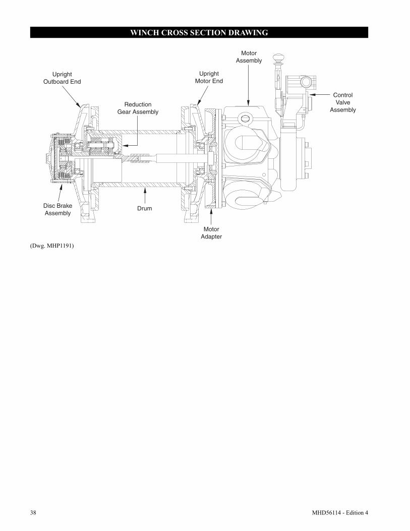
38 MHD56114 - Edition 4
WINCH CROSS SECTION DRAWING
(Dwg. MHP1191)
MotorAdapter
MotorAssembly
DrumDisc BrakeAssembly
UprightOutboard End
ReductionGear Assembly
UprightMotor End
ControlValve
Assembly
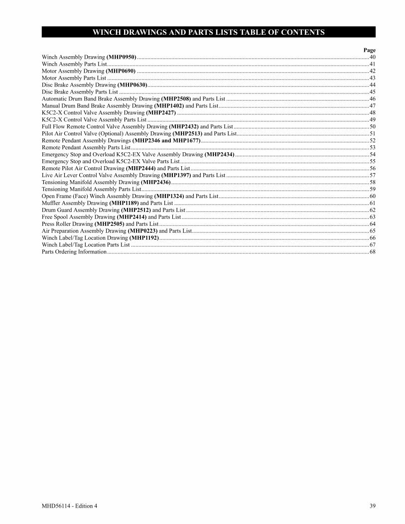
MHD56114 - Edition 4 39
WINCH DRAWINGS AND PARTS LISTS TABLE OF CONTENTS
PageWinch Assembly Drawing (MHP0950) ............................................................................................................................................................40Winch Assembly Parts List................................................................................................................................................................................41Motor Assembly Drawing (MHP0690) ............................................................................................................................................................42Motor Assembly Parts List ................................................................................................................................................................................43Disc Brake Assembly Drawing (MHP0630).....................................................................................................................................................44Disc Brake Assembly Parts List ........................................................................................................................................................................45Automatic Drum Band Brake Assembly Drawing (MHP2508) and Parts List ................................................................................................46Manual Drum Band Brake Assembly Drawing (MHP1402) and Parts List.....................................................................................................47K5C2-X Control Valve Assembly Drawing (MHP2427) .................................................................................................................................48K5C2-X Control Valve Assembly Parts List .....................................................................................................................................................49Full Flow Remote Control Valve Assembly Drawing (MHP2432) and Parts List ...........................................................................................50Pilot Air Control Valve (Optional) Assembly Drawing (MHP2513) and Parts List.........................................................................................51Remote Pendant Assembly Drawings (MHP2346 and MHP1677) .................................................................................................................52Remote Pendant Assembly Parts List ................................................................................................................................................................53Emergency Stop and Overload K5C2-EX Valve Assembly Drawing (MHP2434) ..........................................................................................54Emergency Stop and Overload K5C2-EX Valve Parts List ...............................................................................................................................55Remote Pilot Air Control Drawing (MHP2444) and Parts List ........................................................................................................................56Live Air Lever Control Valve Assembly Drawing (MHP1397) and Parts List ................................................................................................57Tensioning Manifold Assembly Drawing (MHP2436) .....................................................................................................................................58Tensioning Manifold Assembly Parts List.........................................................................................................................................................59Open Frame (Face) Winch Assembly Drawing (MHP1324) and Parts List.....................................................................................................60Muffler Assembly Drawing (MHP1189) and Parts List ...................................................................................................................................61Drum Guard Assembly Drawing (MHP2512) and Parts List ...........................................................................................................................62Free Spool Assembly Drawing (MHP2414) and Parts List ..............................................................................................................................63Press Roller Drawing (MHP2505) and Parts List .............................................................................................................................................64Air Preparation Assembly Drawing (MHP0223) and Parts List.......................................................................................................................65Winch Label/Tag Location Drawing (MHP1192).............................................................................................................................................66Winch Label/Tag Location Parts List ................................................................................................................................................................67Parts Ordering Information................................................................................................................................................................................68
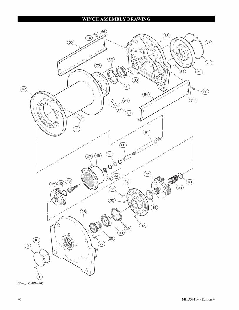
40 MHD56114 - Edition 4
WINCH ASSEMBLY DRAWING
(Dwg. MHP0950)
74
26
27
28
3029
1
2
18
68
73
70
7153
29
30
62
81
64
72
67
63
66
66
65
33
61
60
48 58
4644
47
434042
32
34
33
35
32
39
36
40
74
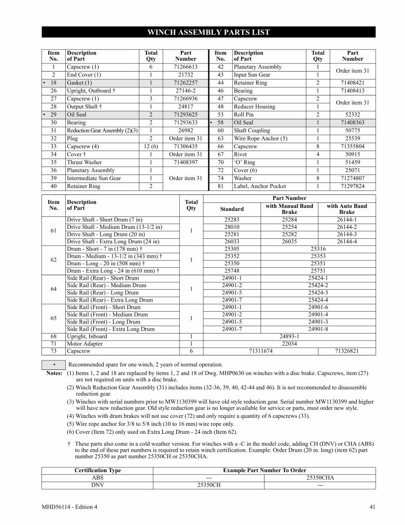
MHD56114 - Edition 4 41
WINCH ASSEMBLY PARTS LIST
ItemNo.
Descriptionof Part
TotalQty
PartNumber
ItemNo.
Descriptionof Part
TotalQty
PartNumber
1 Capscrew (1) 6 71266613 42 Planetary Assembly 1Order item 31
2 End Cover (1) 1 21732 43 Input Sun Gear 1• 18 Gasket (1) 1 71262257 44 Retainer Ring 2 71408421
26 Upright, Outboard † 1 27146-2 46 Bearing 1 7140841327 Capscrew (1) 3 71266936 47 Capscrew 2
Order item 3128 Output Shaft † 1 24817 48 Reducer Housing 1
• 29 Oil Seal 2 71293625 53 Roll Pin 2 5233230 Bearing 2 71293633 • 58 Oil Seal 1 7140836331 Reduction Gear Assembly (2)(3) 1 26982 60 Shaft Coupling 1 50775 32 Plug 2 Order item 31 63 Wire Rope Anchor (5) 1 2553933 Capscrew (4) 12 (6) 71306435 66 Capscrew 8 7135580434 Cover † 1 Order item 31 67 Rivet 4 5091535 Thrust Washer 1 71408397 70 ‘O’ Ring 1 5145936 Planetary Assembly 1
Order item 3172 Cover (6) 1 25071
39 Intermediate Sun Gear 1 74 Washer 8 7127480740 Retainer Ring 2 81 Label, Anchor Pocket 1 71297824
ItemNo.
Descriptionof Part
TotalQty
Part Number
Standard with Manual Band Brake
with Auto Band Brake
61
Drive Shaft - Short Drum (7 in)
1
25283 25284 26144-1Drive Shaft - Medium Drum (13-1/2 in) 28010 25254 26144-2Drive Shaft - Long Drum (20 in) 25281 25282 26144-3Drive Shaft - Extra Long Drum (24 in) 26033 26035 26144-4
62
Drum - Short - 7 in (178 mm) †
1
25305 25316Drum - Medium - 13-1/2 in (343 mm) † 25352 25353Drum - Long - 20 in (508 mm) † 25350 25351Drum - Extra Long - 24 in (610 mm) † 25748 25751
64
Side Rail (Rear) - Short Drum
1
24901-1 25424-1Side Rail (Rear) - Medium Drum 24901-2 25424-2Side Rail (Rear) - Long Drum 24901-5 25424-3Side Rail (Rear) - Extra Long Drum 24901-7 25424-4
65
Side Rail (Front) - Short Drum
1
24901-1 24901-6Side Rail (Front) - Medium Drum 24901-2 24901-4Side Rail (Front) - Long Drum 24901-5 24901-3Side Rail (Front) - Extra Long Drum 24901-7 24901-8
68 Upright, Inboard 1 24893-171 Motor Adapter 1 2203473 Capscrew 6 71311674 71326821
• Recommended spare for one winch, 2 years of normal operation.Notes: (1) Items 1, 2 and 18 are replaced by items 1, 2 and 18 of Dwg. MHP0630 on winches with a disc brake. Capscrews, item (27)
are not required on units with a disc brake.(2) Winch Reduction Gear Assembly (31) includes items (32-36, 39, 40, 42-44 and 46). It is not recommended to disassemble
reduction gear.(3) Winches with serial numbers prior to MW1130399 will have old style reduction gear. Serial number MW1130399 and higher
will have new reduction gear. Old style reduction gear is no longer available for service or parts, must order new style.(4) Winches with drum brakes will not use cover (72) and only require a quantity of 6 capscrews (33).(5) Wire rope anchor for 3/8 to 5/8 inch (10 to 16 mm) wire rope only.(6) Cover (Item 72) only used on Extra Long Drum - 24 inch (Item 62).
† These parts also come in a cold weather version. For winches with a -C in the model code, adding CH (DNV) or CHA (ABS) to the end of these part numbers is required to retain winch certification. Example: Order Drum (20 in. long) (item 62) part number 25350 as part number 25350CH or 25350CHA.
Certification Type Example Part Number To OrderABS --- 25350CHADNV 25350CH ---
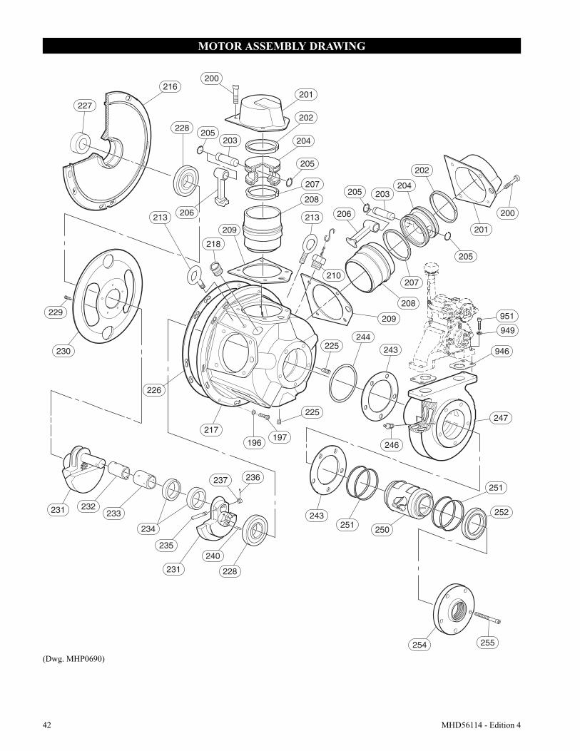
42 MHD56114 - Edition 4
MOTOR ASSEMBLY DRAWING
(Dwg. MHP0690)
216
227
228
213
210
206213
230
226
217
196197
225
243
250
251
251
252
254 255
218
205 203
201
200
205
209
225244
243 946
247
246
208
207
204
202
231 232233
234
237 236
235
231
240
228
200
205203
201
202
204
205
208
207
209
206
951
949
229
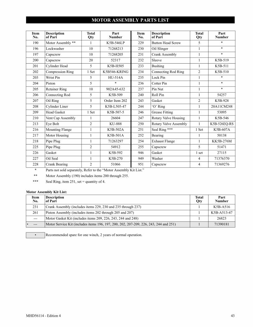
MHD56114 - Edition 4 43
MOTOR ASSEMBLY PARTS LIST
Motor Assembly Kit List:
ItemNo.
Descriptionof Part
TotalQty
PartNumber
ItemNo.
Descriptionof Part
TotalQty
PartNumber
190 Motor Assembly ** 1 K5B-546LP 229 Button Head Screw 5 *196 Lockwasher 10 71268213 230 Oil Slinger 1 *197 Capscrew 10 71268205 231 Crank Assembly 1 *200 Capscrew 20 52317 232 Sleeve 1 K5B-519201 Cylinder Head 5 K5B-H505 233 Bushing 1 K5B-511202 Compression Ring 1 Set K5B546-KRING 234 Connecting Rod Ring 2 K5B-510203 Wrist Pin 5 HU-514A 235 Lock Pin 1 *204 Piston 5 * 236 Cotter Pin 1 *205 Retainer Ring 10 902A45-632 237 Pin Nut 1 *206 Connecting Rod 5 K5B-509 240 Roll Pin 1 54257207 Oil Ring 5 Order Item 202 243 Gasket 2 K5B-928208 Cylinder Liner 5 K5B-L505-47 244 ‘O’ Ring 1 20A11CM248209 Head Gasket 1 Set K5B-507-5 246 Grease Fitting 1 53095210 Vent Cap Assembly 1 26604 247 Rotary Valve Housing 1 K5B-546213 Eye Bolt 2 KU-888 250 Rotary Valve Assembly 1 K5B-526EQ-RS216 Mounting Flange 1 K5B-502A 251 Seal Ring *** 1 Set K5B-607A217 Motor Housing 1 K5B-501A 252 Bearing 1 50138218 Pipe Plug 1 71263297 254 Exhaust Flange 1 KK5B-276M225 Pipe Plug 2 54912 255 Capscrew 5 51471226 Gasket 1 K5B-592 946 Gasket 1 set 27115227 Oil Seal 1 K5B-270 949 Washer 4 71376370228 Crank Bearing 2 51066 951 Capscrew 4 71369276
* Parts not sold separately, Refer to the “Motor Assembly Kit List.”** Motor Assembly (190) includes items 200 through 255.
*** Seal Ring, item 251, set = quantity of 4.
ItemNo.
Descriptionof Part
TotalQty
PartNumber
231 Crank Assembly (includes items 229, 230 and 235 through 237) 1 K5B-A516261 Piston Assembly (includes items 202 through 205 and 207) 1 K5B-A513-47--- Motor Gasket Kit (includes items 209, 226, 243, 244 and 248) 1 26823
• --- Motor Service Kit (includes items 196, 197, 200, 202, 207-209, 226, 243, 244 and 251) 1 71390181
• Recommended spare for one winch, 2 years of normal operation.
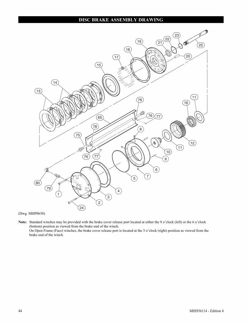
44 MHD56114 - Edition 4
DISC BRAKE ASSEMBLY DRAWING
(Dwg. MHP0630)
Note: Standard winches may be provided with the brake cover release port located at either the 9 o’clock (left) or the 6 o’clock (bottom) position as viewed from the brake end of the winch. On Open Frame (Face) winches, the brake cover release port is located at the 3 o’clock (right) position as viewed from the brake end of the winch.
11
16
15
13
14
17
19
20
2122
23
2518
8
9
242
3
4
5
6
7
1011
12
80
79
75
65
76 77
78
76 77
78
1
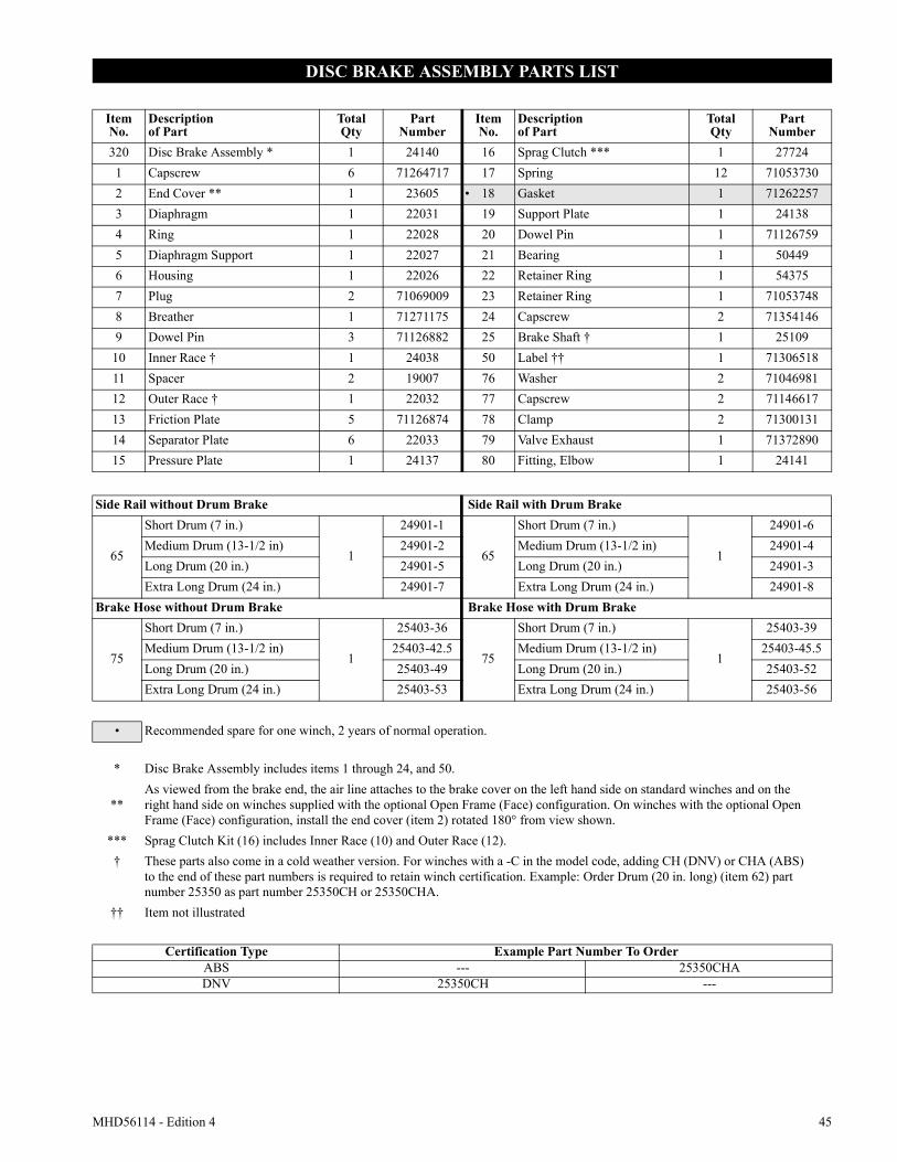
MHD56114 - Edition 4 45
DISC BRAKE ASSEMBLY PARTS LIST
ItemNo.
Descriptionof Part
TotalQty
PartNumber
ItemNo.
Descriptionof Part
TotalQty
PartNumber
320 Disc Brake Assembly * 1 24140 16 Sprag Clutch *** 1 277241 Capscrew 6 71264717 17 Spring 12 710537302 End Cover ** 1 23605 • 18 Gasket 1 712622573 Diaphragm 1 22031 19 Support Plate 1 241384 Ring 1 22028 20 Dowel Pin 1 711267595 Diaphragm Support 1 22027 21 Bearing 1 504496 Housing 1 22026 22 Retainer Ring 1 543757 Plug 2 71069009 23 Retainer Ring 1 710537488 Breather 1 71271175 24 Capscrew 2 713541469 Dowel Pin 3 71126882 25 Brake Shaft † 1 25109
10 Inner Race † 1 24038 50 Label †† 1 7130651811 Spacer 2 19007 76 Washer 2 7104698112 Outer Race † 1 22032 77 Capscrew 2 7114661713 Friction Plate 5 71126874 78 Clamp 2 7130013114 Separator Plate 6 22033 79 Valve Exhaust 1 7137289015 Pressure Plate 1 24137 80 Fitting, Elbow 1 24141
Side Rail without Drum Brake Side Rail with Drum Brake
65
Short Drum (7 in.)
1
24901-1
65
Short Drum (7 in.)
1
24901-6Medium Drum (13-1/2 in) 24901-2 Medium Drum (13-1/2 in) 24901-4Long Drum (20 in.) 24901-5 Long Drum (20 in.) 24901-3Extra Long Drum (24 in.) 24901-7 Extra Long Drum (24 in.) 24901-8
Brake Hose without Drum Brake Brake Hose with Drum Brake
75
Short Drum (7 in.)
1
25403-36
75
Short Drum (7 in.)
1
25403-39Medium Drum (13-1/2 in) 25403-42.5 Medium Drum (13-1/2 in) 25403-45.5Long Drum (20 in.) 25403-49 Long Drum (20 in.) 25403-52Extra Long Drum (24 in.) 25403-53 Extra Long Drum (24 in.) 25403-56
• Recommended spare for one winch, 2 years of normal operation.
* Disc Brake Assembly includes items 1 through 24, and 50.
**As viewed from the brake end, the air line attaches to the brake cover on the left hand side on standard winches and on the right hand side on winches supplied with the optional Open Frame (Face) configuration. On winches with the optional Open Frame (Face) configuration, install the end cover (item 2) rotated 180° from view shown.
*** Sprag Clutch Kit (16) includes Inner Race (10) and Outer Race (12).† These parts also come in a cold weather version. For winches with a -C in the model code, adding CH (DNV) or CHA (ABS)
to the end of these part numbers is required to retain winch certification. Example: Order Drum (20 in. long) (item 62) part number 25350 as part number 25350CH or 25350CHA.
†† Item not illustrated
Certification Type Example Part Number To OrderABS --- 25350CHADNV 25350CH ---
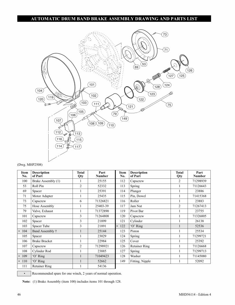
46 MHD56114 - Edition 4
AUTOMATIC DRUM BAND BRAKE ASSEMBLY DRAWING AND PARTS LIST
(Dwg. MHP2508)
104
119120
101
102
103
105
107
106
110
79
111
109
113112
108
116
114
115
117
149
126
125127
124128
123
75
122
121
73
71
5369
ItemNo.
Descriptionof Part
TotalQty
PartNumber
ItemNo.
Descriptionof Part
TotalQty
PartNumber
100 Brake Assembly (1) 1 25155 112 Capscrew 2 7129893953 Roll Pin 2 52332 113 Spring 1 7112664369 Spacer 1 25391 114 Plunger 1 2388671 Motor Adapter 1 25435 115 Pin, Dowel 1 7141536873 Capscrew 6 71326821 116 Roller 1 2388375 Hose Assembly 1 25403-39 117 Jam Nut 2 7126741379 Valve, Exhaust 1 71372890 119 Pivot Bar 1 23755
101 Capscrew 3 71264808 120 Capscrew 1 71326805102 Spacer 3 21899 121 Cylinder 1 26138103 Spacer Tube 3 21891 • 122 ‘O’ Ring 1 52536
• 104 Band Assembly † 1 25144 123 Piston 1 25534105 Spacer 1 23029 124 Spring 1 71299721106 Brake Bracket 1 22984 125 Cover 1 25392107 Capscrew 2 71298921 126 Retainer Ring 1 71126668108 Cylinder Rod 1 23885 127 Spring 1 71299713
• 109 ‘O’ Ring 1 71049423 128 Washer 1 71145080• 110 ‘O’ Ring 1 52662 149 Fitting, Nipple 1 52092
111 Retainer Ring 1 54136
• Recommended spare for one winch, 2 years of normal operation.
Note: (1) Brake Assembly (item 100) includes items 101 through 128.
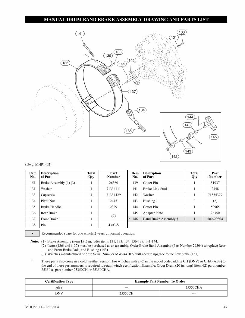
MHD56114 - Edition 4 47
MANUAL DRUM BAND BRAKE ASSEMBLY DRAWING AND PARTS LIST
(Dwg. MHP1402)
144
131133
137
134
135
138
141
139
136145
143
143
144
142
145
ItemNo.
Descriptionof Part
TotalQty
PartNumber
ItemNo.
Descriptionof Part
TotalQty
PartNumber
151 Brake Assembly (1) (3) 1 26360 139 Cotter Pin 1 51937
131 Washer 4 71334411 141 Brake Link Stud 1 2448
133 Capscrew 4 71334429 142 Washer 1 71334379
134 Pivot Nut 1 2445 143 Bushing 2 (2)
135 Brake Handle 1 2329 144 Cotter Pin 1 50965
136 Rear Brake 1(2)
145 Adapter Plate 1 26350
137 Front Brake 1 • 146 Band Brake Assembly † 1 382-29304
138 Pin 1 4303-S
• Recommended spare for one winch, 2 years of normal operation.
Note: (1) Brake Assembly (item 151) includes items 131, 133, 134, 136-139, 141-144. (2) Items (136) and (137) must be purchased as an assembly. Order Brake Band Assembly (Part Number 29304) to replace Rear
and Front Brake Pads, and Bushing (143).(3) Winches manufactured prior to Serial Number MW2441097 will need to upgrade to the new brake (151).
† These parts also come in a cold weather version. For winches with a -C in the model code, adding CH (DNV) or CHA (ABS) to the end of these part numbers is required to retain winch certification. Example: Order Drum (20 in. long) (item 62) part number 25350 as part number 25350CH or 25350CHA.
Certification Type Example Part Number To Order
ABS --- 25350CHA
DNV 25350CH ---
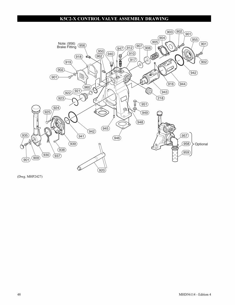
48 MHD56114 - Edition 4
K5C2-X CONTROL VALVE ASSEMBLY DRAWING
(Dwg. MHP2427)
Note: (956)Brake Fitting
909
Optional
948
949
902903901
955
951
218
942
943
944
912 907906
904905
917
916
918
956
919
921922
902
901
945
946935
901930 937
939
941
938
925924
942
923
962950
960
957
958
959
940
947
910
920
901
902
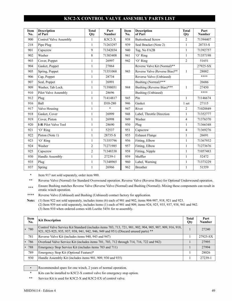
MHD56114 - Edition 4 49
K5C2-X CONTROL VALVE ASSEMBLY PARTS LIST
ItemNo.
Descriptionof Part
TotalQty
PartNumber
ItemNo.
Descriptionof Part
TotalQty
PartNumber
900 Control Valve Assembly 1 K5C2-X 938 Buttonhead Screw 2 71394407218 Pipe Plug 1 71263297 939 Seal Bracket (Note 2) 1 28733-S901 Capscrew 9 71342034 940 Tag, No FA2B 1 71392757902 Washer 8 71303408 941 ‘O’ Ring 1 71357198903 Cover, Poppet 1 26997 942 ‘O’ Ring 2 51651904 Gasket, Poppet 1 27064
943Reverse Valve Kit (Normal)**
127925-SX
905 Spring, Poppet 1 71351068 Reverse Valve (Reverse Bias)** 28002906 Cap, Poppet 1 28734 Reverse Valve (Unbiased) ****907 Seal, Poppet 1 26991
944Bushing (Normal)***
126686
909 Washer, Tab Lock 1 71398051 Bushing (Reverse Bias)*** 27450910 Pilot Valve Assembly 1 28696 Bushing (Unbiased) ****912 Plug 1 71414817 945 Pin 1 71146674916 Ball 1 D10-280 946 Gasket 1 set 27115917 Valve Housing 1 * 947 Rivet 2 71028849918 Gasket, Cover 1 26999 948 Label, Throttle Direction 1 71352777919 Cover, Piston 1 26998 949 Washer 4 71376370920 I-R Pilot Valve Tool 1 28690 950 Plug 1 71366348921 ‘O’ Ring 1 52537 951 Capscrew 4 71369276922 Piston (Note 1) 1 28735-S 955 Exhaust Flange 1 26691923 ‘O’ Ring 1 71355796 956 Fitting, Elbow 1 71367932924 Washer 2 71271985 957 Fitting, Elbow 1 71273676925 Capscrew 2 71348338 958 Fitting, Nipple 1 71057483930 Handle Assembly 1 27239-1 959 Muffler 1 52472935 Plug 1 71348965 960 Label, Warning 1 71373229937 Spring 1 26966 962 Breather 1 51559
* Item 917 not sold separately, order item 900.** Reverse Valve (Normal) for Standard Overwound operation. Reverse Valve (Reverse Bias) for Optional Underwound operation.
*** Ensure Bushing matches Reverse Valve (Reverse Valve (Normal) and Bushing (Normal)). Mixing these components can result in erratic winch operation.
**** Reverse Valve (Unbiased) and Bushing (Unbiased) contact factory for application.Note: (1) Item 922 not sold separately, includes items (6) each of 901 and 902, items 904-907, 918, 921 and 923.
(2) Item 939 not sold separately, includes items (1) each of 901 and 909, items 924, 925, 935, 937, 938, 941 and 942.(3) Item 910 when ordered comes with Loctite 545® for re-assembly.
Item No. Kit Description Total
QtyPart
Number
• 780 Control Valve Service Kit Standard (includes items 703, 713, 721, 901, 902, 904, 905, 907, 909, 916, 918, 921, 923-925, 935, 937, 938, 941, 942, 946, 949 and 951) (Discard unused parts) ** 1 27240
781 Reverse Valve Kit (includes items 940, 943 and 947) 1 27925-SX• 786 Overload Valve Service Kit (includes items 701, 703, 712 through 714, 716, 722 and 942) 1 27995• 788 Emergency Stop Service Kit (includes items 703 and 711) 1 27994
789 Emergency Stop Kit (Optional Feature)* 1 28026930 Handle Assembly Kit (includes items 901, 909, 930 and 935) 1 27239-1
• Recommended spare for one winch, 2 years of normal operation.* Kits can be installed to K5C2-X control valve for emergency stop option.
** Service Kit is used for K5C2-X and K5C2-EX of control valve.
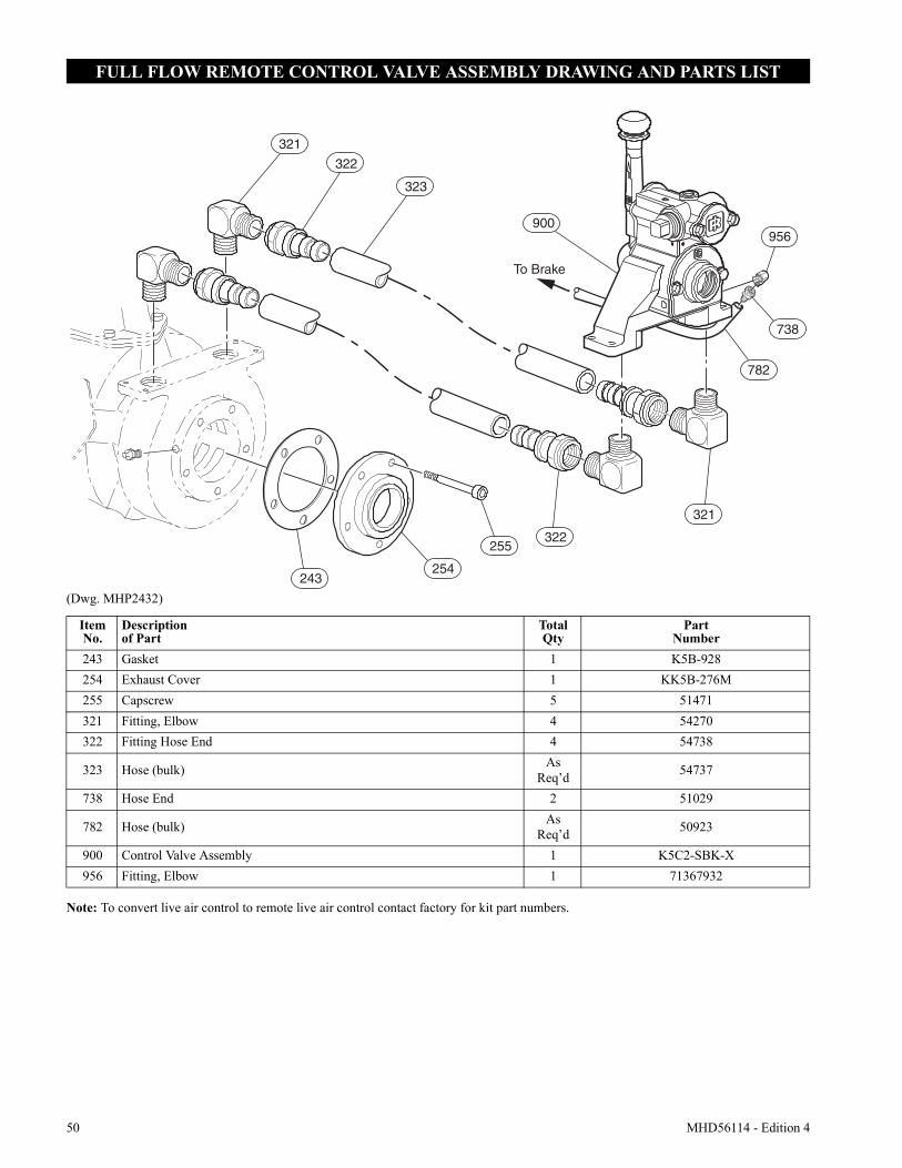
50 MHD56114 - Edition 4
FULL FLOW REMOTE CONTROL VALVE ASSEMBLY DRAWING AND PARTS LIST
(Dwg. MHP2432)
Note: To convert live air control to remote live air control contact factory for kit part numbers.
321
322
323
900
738
956
782
To Brake
321
322255
254243
ItemNo.
Descriptionof Part
TotalQty
Part Number
243 Gasket 1 K5B-928254 Exhaust Cover 1 KK5B-276M255 Capscrew 5 51471321 Fitting, Elbow 4 54270322 Fitting Hose End 4 54738
323 Hose (bulk) As Req’d 54737
738 Hose End 2 51029
782 Hose (bulk) As Req’d 50923
900 Control Valve Assembly 1 K5C2-SBK-X956 Fitting, Elbow 1 71367932
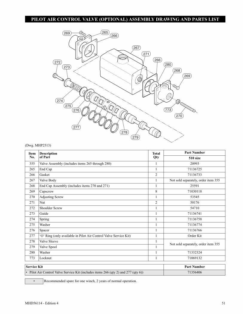
MHD56114 - Edition 4 51
PILOT AIR CONTROL VALVE (OPTIONAL) ASSEMBLY DRAWING AND PARTS LIST
(Dwg. MHP2513)
276
277278
279
272273
269 265266
267
271
266280
268
269
773
270
274275
ItemNo.
Descriptionof Part
TotalQty
Part Number510 size
355 Valve Assembly (includes items 265 through 280) 1 20993265 End Cap 1 71136725266 Gasket 2 71136733267 Valve Body 1 Not sold separately, order item 355268 End Cap Assembly (includes items 270 and 271) 1 25591269 Capscrew 8 71030118270 Adjusting Screw 1 53545271 Nut 2 50176272 Shoulder Screw 1 54710273 Guide 1 71136741274 Spring 1 71136758275 Washer 1 71136774276 Spacer 1 71136766277 ‘O’ Ring (only available in Pilot Air Control Valve Service Kit) 1 Order Kit278 Valve Sleeve 1
Not sold separately, order item 355279 Valve Spool 1280 Washer 1 71332324773 Locknut 1 71069132
Service Kit Part Number• Pilot Air Control Valve Service Kit (includes items 266 (qty 2) and 277 (qty 6)) 71356406
• Recommended spare for one winch, 2 years of normal operation.
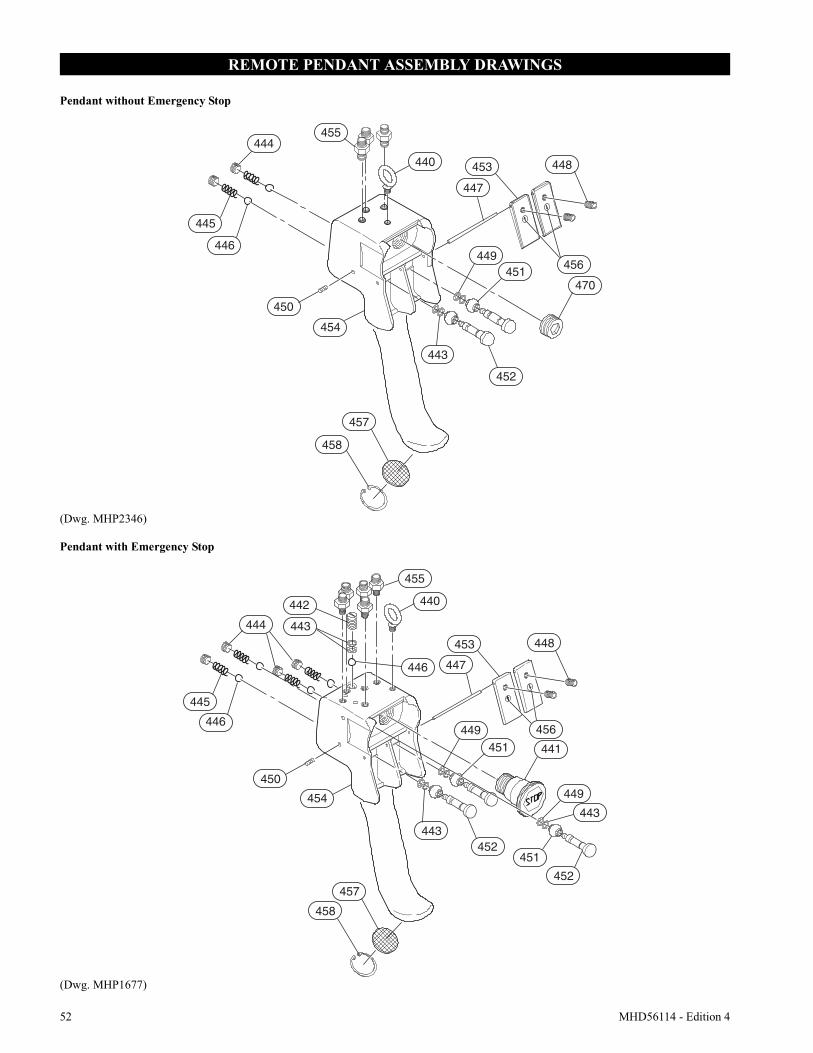
52 MHD56114 - Edition 4
REMOTE PENDANT ASSEMBLY DRAWINGS
Pendant without Emergency Stop
(Dwg. MHP2346)
Pendant with Emergency Stop
(Dwg. MHP1677)
445
446
444455
440
456
447
453 448
449451
470
452
443
450
454
457
458
445
446
444
442
443
455
440
446 447
453 448
456449451 441
454
457
458
443452
451
452
449
443
450
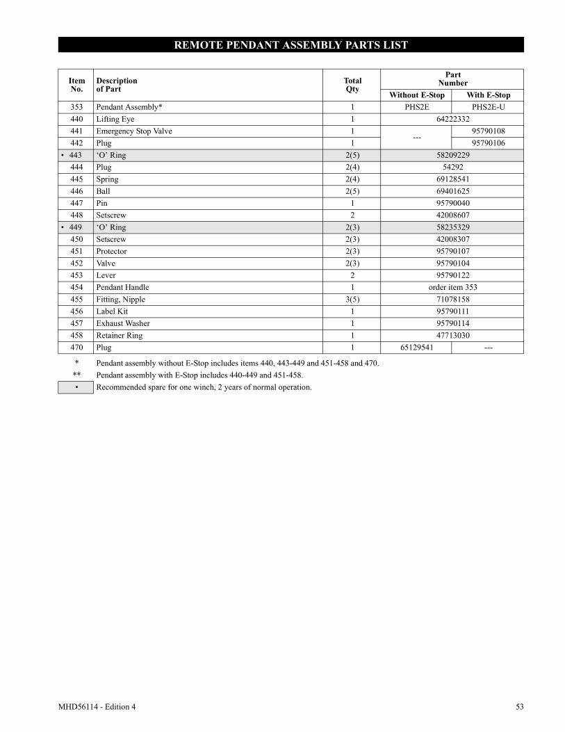
MHD56114 - Edition 4 53
REMOTE PENDANT ASSEMBLY PARTS LIST
ItemNo.
Descriptionof Part
TotalQty
PartNumber
Without E-Stop With E-Stop353 Pendant Assembly* 1 PHS2E PHS2E-U440 Lifting Eye 1 64222332441 Emergency Stop Valve 1
---95790108
442 Plug 1 95790106• 443 ‘O’ Ring 2(5) 58209229
444 Plug 2(4) 54292445 Spring 2(4) 69128541446 Ball 2(5) 69401625447 Pin 1 95790040448 Setscrew 2 42008607
• 449 ‘O’ Ring 2(3) 58235329450 Setscrew 2(3) 42008307451 Protector 2(3) 95790107452 Valve 2(3) 95790104453 Lever 2 95790122454 Pendant Handle 1 order item 353455 Fitting, Nipple 3(5) 71078158456 Label Kit 1 95790111457 Exhaust Washer 1 95790114458 Retainer Ring 1 47713030470 Plug 1 65129541 ---
* Pendant assembly without E-Stop includes items 440, 443-449 and 451-458 and 470.** Pendant assembly with E-Stop includes 440-449 and 451-458.• Recommended spare for one winch, 2 years of normal operation.
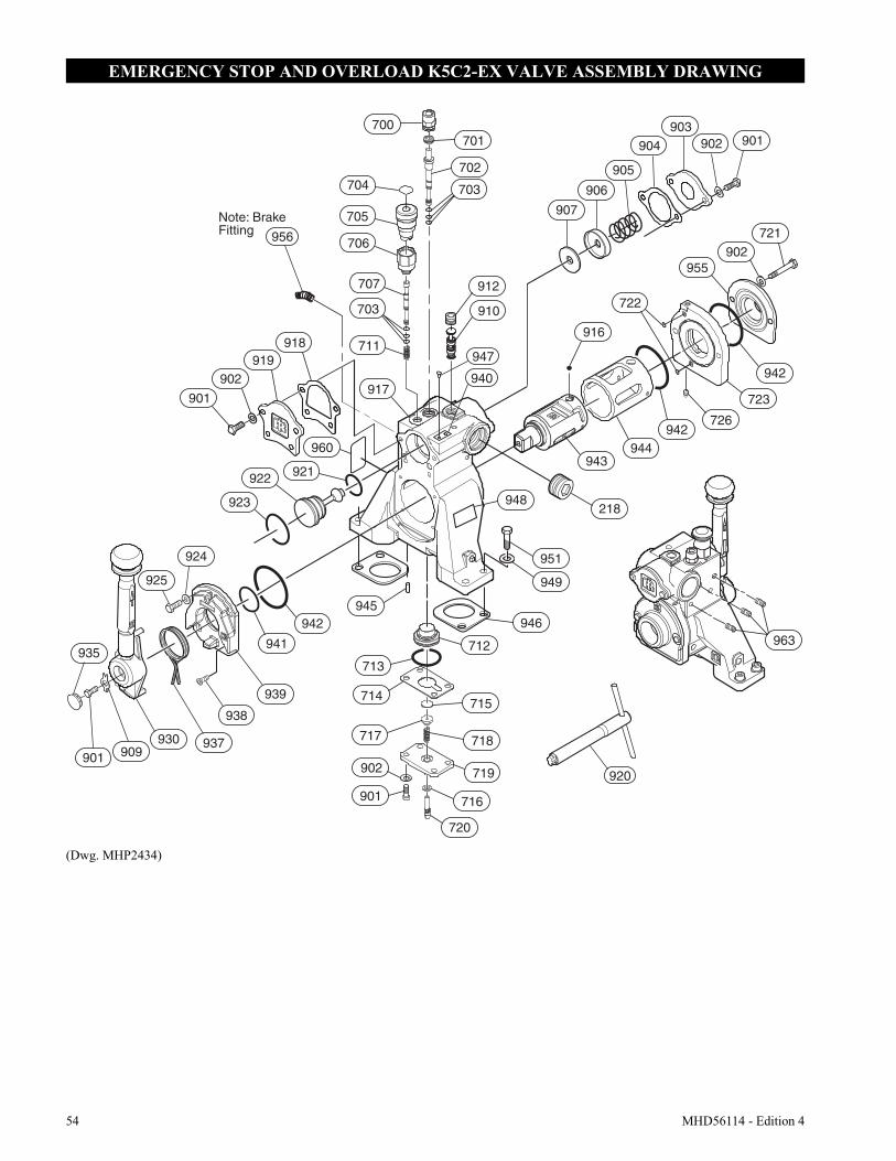
54 MHD56114 - Edition 4
EMERGENCY STOP AND OVERLOAD K5C2-EX VALVE ASSEMBLY DRAWING
(Dwg. MHP2434)
Note: Brake Fitting
948
920
906
956
912
910
917
711
703
707
706
705
918919
902
704 703
702
701700
940
947
901
922
923
921
960
901 909930 937
938
939
941
942
925
924
935963
944
955902
942
721
722
942
723
726
943
716
719
718
715
916
946
949
951
218
901
902
720
717
714
712
713
945
901902903
904
905
907
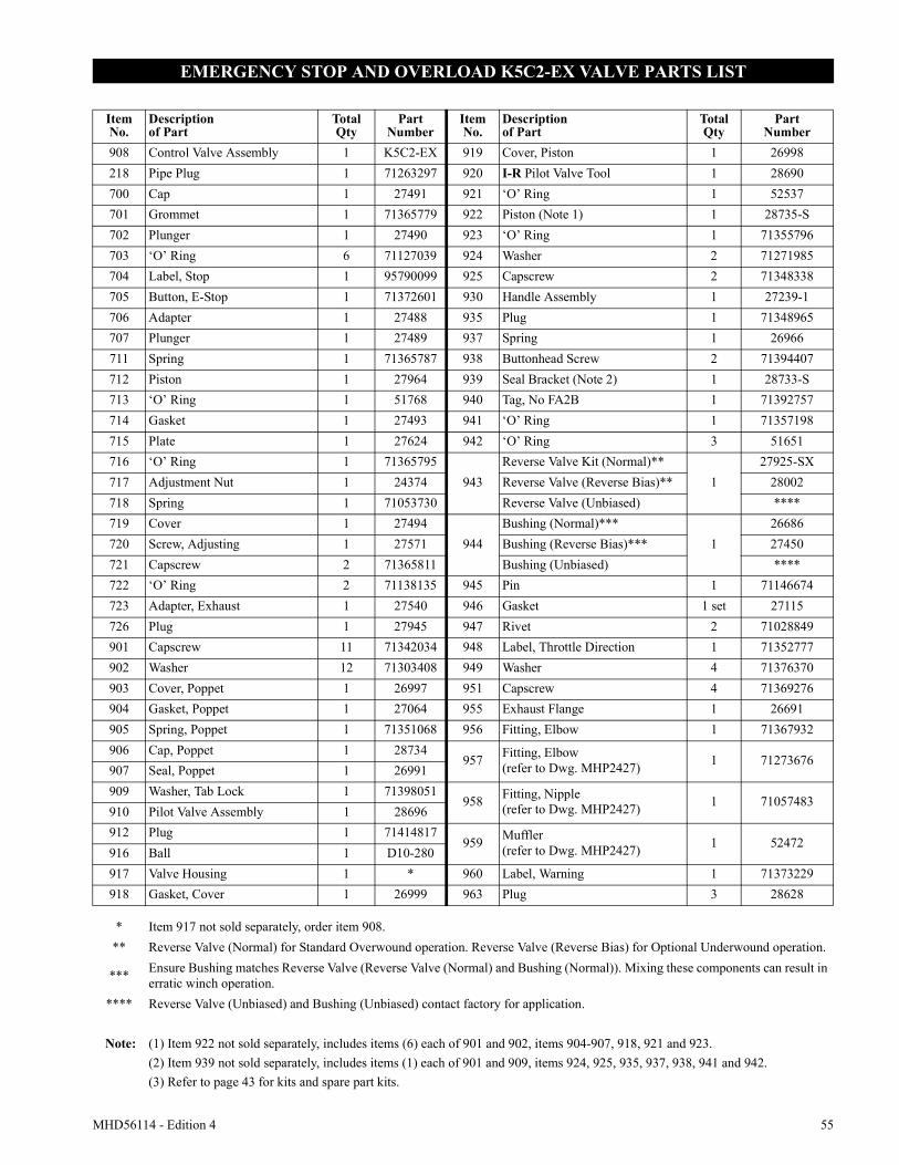
MHD56114 - Edition 4 55
EMERGENCY STOP AND OVERLOAD K5C2-EX VALVE PARTS LIST
ItemNo.
Descriptionof Part
TotalQty
PartNumber
ItemNo.
Descriptionof Part
TotalQty
PartNumber
908 Control Valve Assembly 1 K5C2-EX 919 Cover, Piston 1 26998218 Pipe Plug 1 71263297 920 I-R Pilot Valve Tool 1 28690700 Cap 1 27491 921 ‘O’ Ring 1 52537701 Grommet 1 71365779 922 Piston (Note 1) 1 28735-S702 Plunger 1 27490 923 ‘O’ Ring 1 71355796703 ‘O’ Ring 6 71127039 924 Washer 2 71271985704 Label, Stop 1 95790099 925 Capscrew 2 71348338705 Button, E-Stop 1 71372601 930 Handle Assembly 1 27239-1706 Adapter 1 27488 935 Plug 1 71348965707 Plunger 1 27489 937 Spring 1 26966711 Spring 1 71365787 938 Buttonhead Screw 2 71394407712 Piston 1 27964 939 Seal Bracket (Note 2) 1 28733-S713 ‘O’ Ring 1 51768 940 Tag, No FA2B 1 71392757714 Gasket 1 27493 941 ‘O’ Ring 1 71357198715 Plate 1 27624 942 ‘O’ Ring 3 51651716 ‘O’ Ring 1 71365795
943Reverse Valve Kit (Normal)**
127925-SX
717 Adjustment Nut 1 24374 Reverse Valve (Reverse Bias)** 28002718 Spring 1 71053730 Reverse Valve (Unbiased) ****719 Cover 1 27494
944Bushing (Normal)***
126686
720 Screw, Adjusting 1 27571 Bushing (Reverse Bias)*** 27450721 Capscrew 2 71365811 Bushing (Unbiased) ****722 ‘O’ Ring 2 71138135 945 Pin 1 71146674723 Adapter, Exhaust 1 27540 946 Gasket 1 set 27115726 Plug 1 27945 947 Rivet 2 71028849901 Capscrew 11 71342034 948 Label, Throttle Direction 1 71352777902 Washer 12 71303408 949 Washer 4 71376370903 Cover, Poppet 1 26997 951 Capscrew 4 71369276904 Gasket, Poppet 1 27064 955 Exhaust Flange 1 26691905 Spring, Poppet 1 71351068 956 Fitting, Elbow 1 71367932906 Cap, Poppet 1 28734
957 Fitting, Elbow(refer to Dwg. MHP2427) 1 71273676
907 Seal, Poppet 1 26991909 Washer, Tab Lock 1 71398051
958 Fitting, Nipple(refer to Dwg. MHP2427) 1 71057483
910 Pilot Valve Assembly 1 28696912 Plug 1 71414817
959 Muffler(refer to Dwg. MHP2427) 1 52472
916 Ball 1 D10-280917 Valve Housing 1 * 960 Label, Warning 1 71373229918 Gasket, Cover 1 26999 963 Plug 3 28628
* Item 917 not sold separately, order item 908.** Reverse Valve (Normal) for Standard Overwound operation. Reverse Valve (Reverse Bias) for Optional Underwound operation.
*** Ensure Bushing matches Reverse Valve (Reverse Valve (Normal) and Bushing (Normal)). Mixing these components can result in erratic winch operation.
**** Reverse Valve (Unbiased) and Bushing (Unbiased) contact factory for application.
Note: (1) Item 922 not sold separately, includes items (6) each of 901 and 902, items 904-907, 918, 921 and 923.(2) Item 939 not sold separately, includes items (1) each of 901 and 909, items 924, 925, 935, 937, 938, 941 and 942.(3) Refer to page 43 for kits and spare part kits.
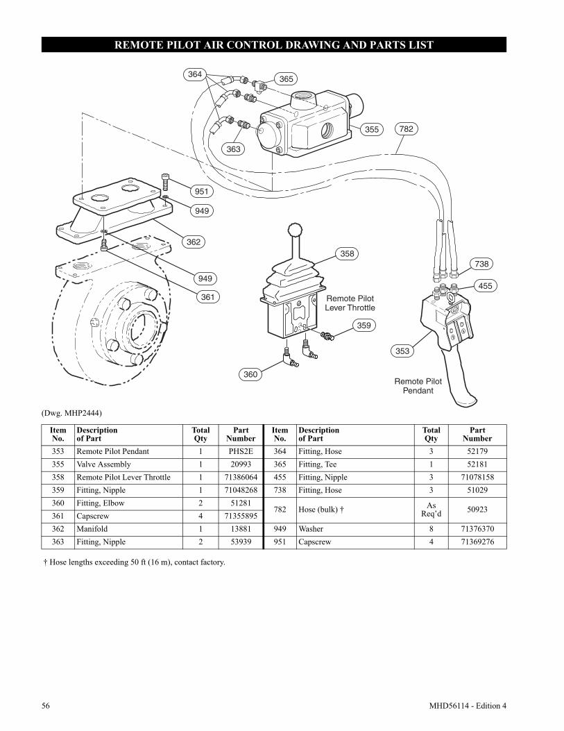
56 MHD56114 - Edition 4
REMOTE PILOT AIR CONTROL DRAWING AND PARTS LIST
(Dwg. MHP2444)
951
364 365
355 782
363
949
362
949
361
360
738
455
353
359
358
Remote PilotLever Throttle
Remote PilotPendant
ItemNo.
Descriptionof Part
TotalQty
PartNumber
ItemNo.
Descriptionof Part
TotalQty
PartNumber
353 Remote Pilot Pendant 1 PHS2E 364 Fitting, Hose 3 52179355 Valve Assembly 1 20993 365 Fitting, Tee 1 52181358 Remote Pilot Lever Throttle 1 71386064 455 Fitting, Nipple 3 71078158359 Fitting, Nipple 1 71048268 738 Fitting, Hose 3 51029360 Fitting, Elbow 2 51281
782 Hose (bulk) † As Req’d 50923
361 Capscrew 4 71355895362 Manifold 1 13881 949 Washer 8 71376370363 Fitting, Nipple 2 53939 951 Capscrew 4 71369276
† Hose lengths exceeding 50 ft (16 m), contact factory.
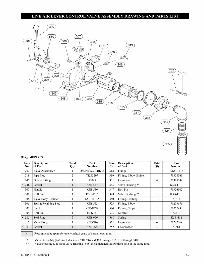
MHD56114 - Edition 4 57
LIVE AIR LEVER CONTROL VALVE ASSEMBLY DRAWING AND PARTS LIST
(Dwg. MHP1397)
300
560
306
307
301
561
752
305331
345
248 348347
752
315316
315
317
318523
524
525
561
308218
350
319
246
ItemNo.
Descriptionof Part
TotalQty
PartNumber
ItemNo.
Descriptionof Part
TotalQty
PartNumber
260 Valve Assembly * 1 Order K5C2-SBK-X 318 Flange 1 KK5B-276218 Pipe Plug 2 71263297 319 Fitting, Elbow Swivel 1 71328561246 Grease Fitting 1 53095 331 Capscrew 4 71325039
• 248 Gasket 1 K5B-547 345 Valve Housing ** 1 K5B-1101300 Handle 1 K5B-556 347 Roll Pin 1 71326102301 Roll Pin 1 K5B-1115 348 Valve Bushing ** 1 K5B-1101305 Valve Body Retainer 1 K5B-1110A 350 Fitting, Bushing 1 51814306 Spring Retaining Stud 1 K5B-553 523 Fitting, Elbow 1 71273676307 Latch 1 K5B-869A 524 Fitting, Nipple 1 71057483308 Roll Pin 1 HLK-20 525 Muffler 1 52472
• 315 Seal Ring 2 K5B-606 • 560 Spring 1 K5B-412316 Valve Body 1 K5B-944 561 Capscrew 4 71292064
• 317 Gasket 1 K5B-275 752 Lockwasher 4 51581
• Recommended spare for one winch, 2 years of normal operation.
***
Valve Assembly (260) includes items 218, 246 and 300 through 316, 318 through 348.Valve Housing (345) and Valve Bushing (348) are a matched set. Replace both at the same time.
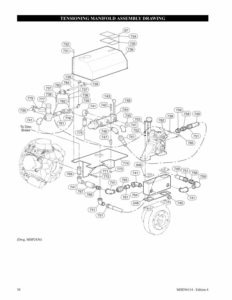
58 MHD56114 - Edition 4
TENSIONING MANIFOLD ASSEMBLY DRAWING
(Dwg. MHP2436)
946
67
732
731
783
739
784 739
736
734
735
737
738777779
739
737
738
739
741
743
742748
744
745
746
747
741
751
752
753 782738
756758 749
751
785
741761
775
769
741767
766
771
772
773
774
741
765
761764
248 745
741
749751
758759
741
741
751
782
776
To DiscBrake
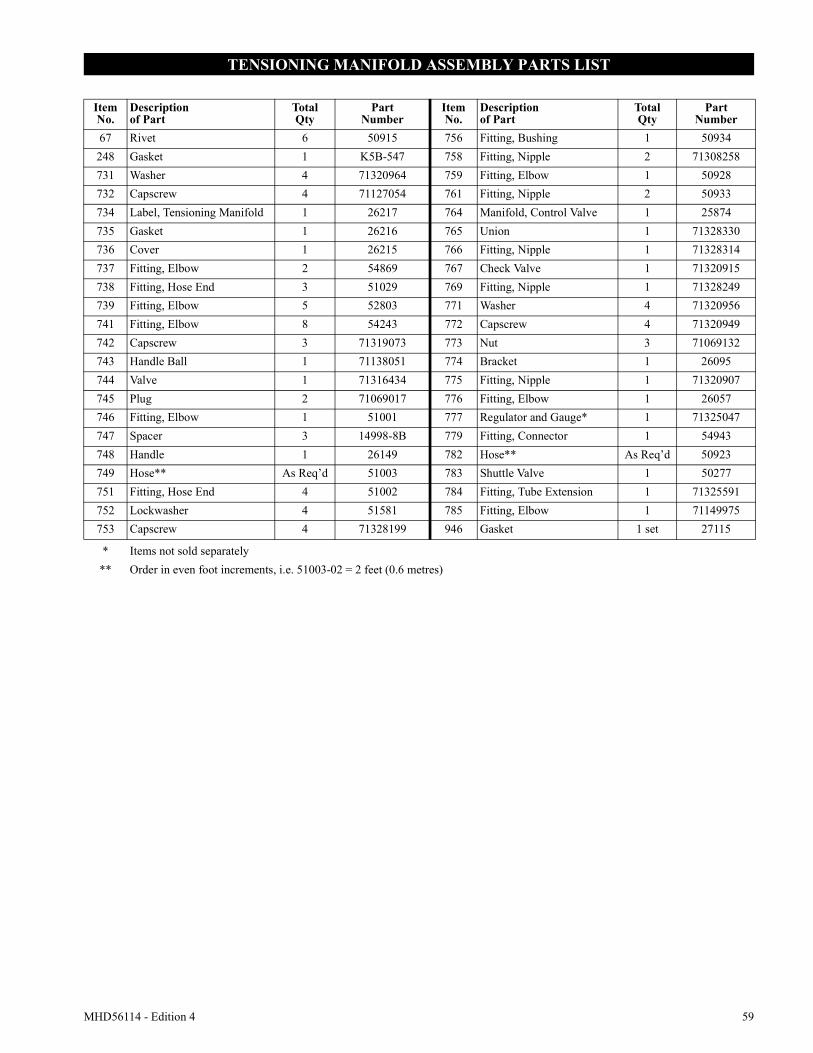
MHD56114 - Edition 4 59
TENSIONING MANIFOLD ASSEMBLY PARTS LIST
ItemNo.
Descriptionof Part
TotalQty
PartNumber
ItemNo.
Descriptionof Part
TotalQty
PartNumber
67 Rivet 6 50915 756 Fitting, Bushing 1 50934248 Gasket 1 K5B-547 758 Fitting, Nipple 2 71308258731 Washer 4 71320964 759 Fitting, Elbow 1 50928732 Capscrew 4 71127054 761 Fitting, Nipple 2 50933734 Label, Tensioning Manifold 1 26217 764 Manifold, Control Valve 1 25874735 Gasket 1 26216 765 Union 1 71328330736 Cover 1 26215 766 Fitting, Nipple 1 71328314737 Fitting, Elbow 2 54869 767 Check Valve 1 71320915738 Fitting, Hose End 3 51029 769 Fitting, Nipple 1 71328249739 Fitting, Elbow 5 52803 771 Washer 4 71320956741 Fitting, Elbow 8 54243 772 Capscrew 4 71320949742 Capscrew 3 71319073 773 Nut 3 71069132743 Handle Ball 1 71138051 774 Bracket 1 26095744 Valve 1 71316434 775 Fitting, Nipple 1 71320907745 Plug 2 71069017 776 Fitting, Elbow 1 26057746 Fitting, Elbow 1 51001 777 Regulator and Gauge* 1 71325047747 Spacer 3 14998-8B 779 Fitting, Connector 1 54943748 Handle 1 26149 782 Hose** As Req’d 50923749 Hose** As Req’d 51003 783 Shuttle Valve 1 50277751 Fitting, Hose End 4 51002 784 Fitting, Tube Extension 1 71325591752 Lockwasher 4 51581 785 Fitting, Elbow 1 71149975753 Capscrew 4 71328199 946 Gasket 1 set 27115
* Items not sold separately** Order in even foot increments, i.e. 51003-02 = 2 feet (0.6 metres)
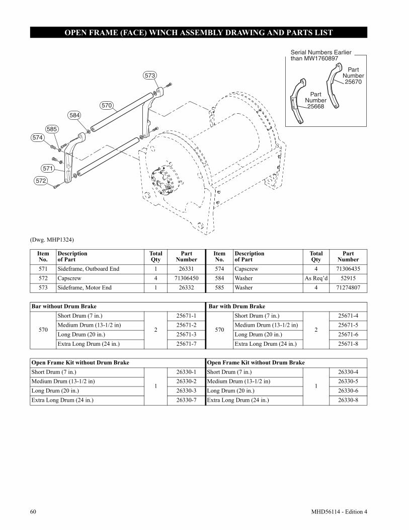
60 MHD56114 - Edition 4
OPEN FRAME (FACE) WINCH ASSEMBLY DRAWING AND PARTS LIST
(Dwg. MHP1324)
Serial Numbers Earlier than MW1760897
PartNumber25670
PartNumber25668
584
573
585574
570
571
572
ItemNo.
Descriptionof Part
TotalQty
PartNumber
ItemNo.
Descriptionof Part
TotalQty
PartNumber
571 Sideframe, Outboard End 1 26331 574 Capscrew 4 71306435572 Capscrew 4 71306450 584 Washer As Req’d 52915573 Sideframe, Motor End 1 26332 585 Washer 4 71274807
Bar without Drum Brake Bar with Drum Brake
570
Short Drum (7 in.)
2
25671-1
570
Short Drum (7 in.)
2
25671-4Medium Drum (13-1/2 in) 25671-2 Medium Drum (13-1/2 in) 25671-5Long Drum (20 in.) 25671-3 Long Drum (20 in.) 25671-6Extra Long Drum (24 in.) 25671-7 Extra Long Drum (24 in.) 25671-8
Open Frame Kit without Drum Brake Open Frame Kit without Drum BrakeShort Drum (7 in.)
1
26330-1 Short Drum (7 in.)
1
26330-4Medium Drum (13-1/2 in) 26330-2 Medium Drum (13-1/2 in) 26330-5Long Drum (20 in.) 26330-3 Long Drum (20 in.) 26330-6Extra Long Drum (24 in.) 26330-7 Extra Long Drum (24 in.) 26330-8
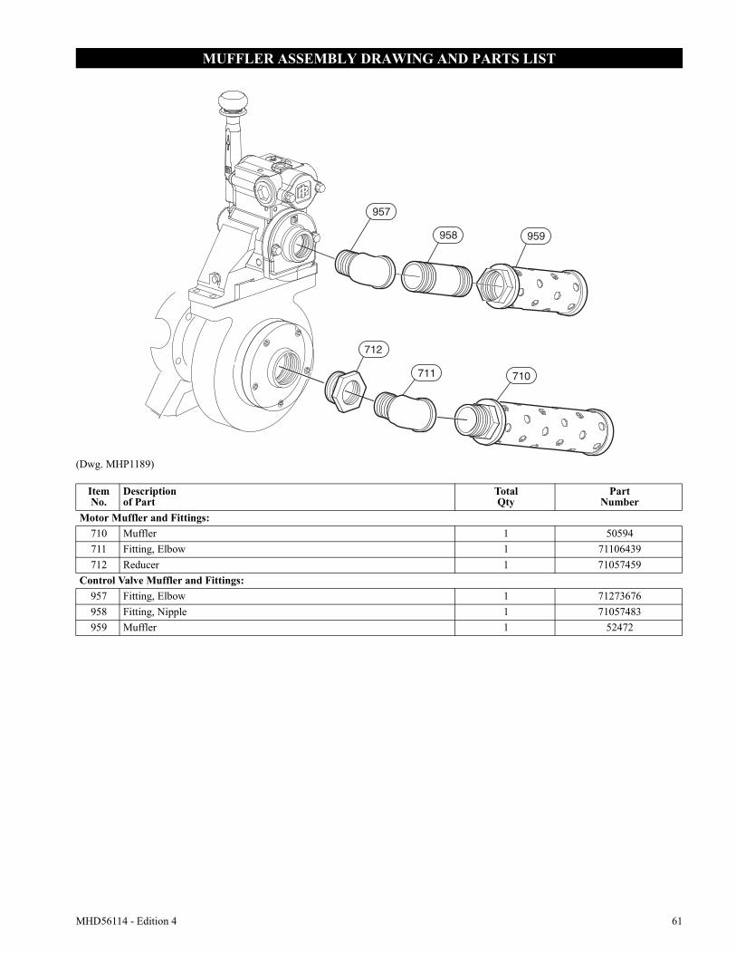
MHD56114 - Edition 4 61
MUFFLER ASSEMBLY DRAWING AND PARTS LIST
(Dwg. MHP1189)
957
959
710711
712
958
ItemNo.
Descriptionof Part
TotalQty
PartNumber
Motor Muffler and Fittings:710 Muffler 1 50594711 Fitting, Elbow 1 71106439712 Reducer 1 71057459
Control Valve Muffler and Fittings:957 Fitting, Elbow 1 71273676958 Fitting, Nipple 1 71057483959 Muffler 1 52472
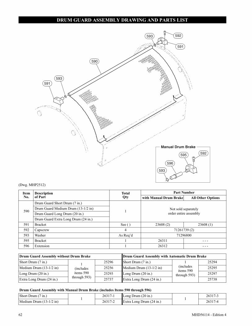
62 MHD56114 - Edition 4
DRUM GUARD ASSEMBLY DRAWING AND PARTS LIST
(Dwg. MHP2512)
591593
590
593 592
591
593
596
595 592
Manual Drum Brake
ItemNo.
Descriptionof Part
TotalQty
Part Numberwith Manual Drum Brake All Other Options
590
Drum Guard Short Drum (7 in.)
1 Not sold separatelyorder entire assembly
Drum Guard Medium Drum (13-1/2 in)Drum Guard Long Drum (20 in.)Drum Guard Extra Long Drum (24 in.)
591 Bracket See ( ) 23608 (2) 23608 (1)592 Capscrew 4 71261739 (2)593 Washer As Req’d 71296800595 Bracket 1 26311 - - -596 Extension 1 26312 - - -
Drum Guard Assembly without Drum Brake Drum Guard Assembly with Automatic Drum BrakeShort Drum (7 in.) 1
(includesitems 590
through 593)
25296 Short Drum (7 in.) 1(includesitems 590
through 593)
25294Medium Drum (13-1/2 in) 25256 Medium Drum (13-1/2 in) 25295Long Drum (20 in.) 25293 Long Drum (20 in.) 25297Extra Long Drum (24 in.) 25737 Extra Long Drum (24 in.) 25738
Drum Guard Assembly with Manual Drum Brake (includes Items 590 through 596)Short Drum (7 in.)
126317-1 Long Drum (20 in.)
126317-3
Medium Drum (13-1/2 in) 26317-2 Extra Long Drum (24 in.) 26317-4
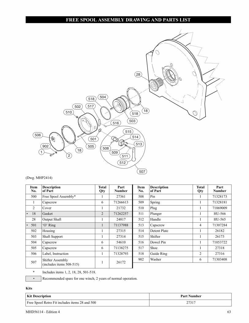
MHD56114 - Edition 4 63
FREE SPOOL ASSEMBLY DRAWING AND PARTS LIST
(Dwg. MHP2414)
Kits
182
1
506
902
501
510
502
505
507
512
514
515
508513
509511
518
517
516503
518
504
18
28
ItemNo.
Descriptionof Part
TotalQty
PartNumber
ItemNo.
Descriptionof Part
TotalQty
PartNumber
500 Free Spool Assembly* 1 27361 508 Pin 1 713281731 Capscrew 6 71266613 509 Spring 1 713281812 Cover 1 21732 510 Plug 1 71069009
• 18 Gasket 2 71262257 511 Plunger 1 HU-56628 Output Shaft 1 24817 512 Handle 1 HU-565
• 501 ‘O’ Ring 1 71137988 513 Capscrew 4 71307284502 Housing 1 27315 514 Detent Plate 1 26182503 Shaft Support 1 27314 515 Shifter 1 26173504 Capscrew 6 54610 516 Dowel Pin 1 71053722505 Capscrew 6 71138275 517 Shoe 1 27318506 Label, Instruction 1 71328793 518 Guide Ring 2 27316
507 Shifter Assembly(includes items 508-515) 1 26172
902 Washer 6 71303408
* Includes items 1, 2, 18, 28, 501-518.
• Recommended spare for one winch, 2 years of normal operation.
Kit Description Part Number
Free Spool Retro Fit includes items 28 and 500 27317
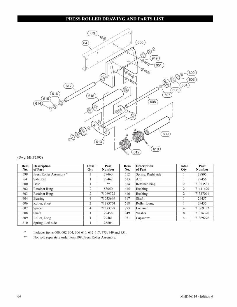
64 MHD56114 - Edition 4
PRESS ROLLER DRAWING AND PARTS LIST
(Dwg. MHP2505)
64
773
600
949
951
602
603
604606
607
608
609
610612
613
614615
616
617
618
ItemNo.
Descriptionof Part
TotalQty
PartNumber
ItemNo.
Descriptionof Part
TotalQty
PartNumber
599 Press Roller Assembly * 1 29460 612 Spring, Right side 1 2880564 Side Rail 1 29462 613 Arm 1 29456
600 Base 1 ** 614 Retainer Ring 2 71053581602 Retainer Ring 2 53050 615 Bushing 2 71411490603 Retainer Ring 2 71069322 616 Bushing 2 71337091604 Bearing 4 71053649 617 Shaft 1 29457606 Roller, Short 2 71383764 618 Roller, Long 1 29455607 Spacer 4 71383798 773 Locknut 4 71069132608 Shaft 1 29458 949 Washer 8 71376370609 Roller, Long 1 29461 951 Capscrew 4 71369276610 Spring, Left side 1 28804
* Includes items 600, 602-604, 606-610, 612-617, 773, 949 and 951.** Not sold separately order item 599, Press Roller Assembly.
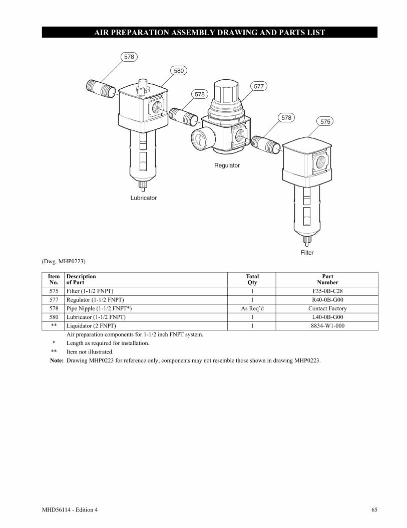
MHD56114 - Edition 4 65
AIR PREPARATION ASSEMBLY DRAWING AND PARTS LIST
(Dwg. MHP0223)
580
578577
578575
Filter
Regulator
Lubricator
578
ItemNo.
Descriptionof Part
TotalQty
PartNumber
575 Filter (1-1/2 FNPT) 1 F35-0B-C28577 Regulator (1-1/2 FNPT) 1 R40-0B-G00578 Pipe Nipple (1-1/2 FNPT*) As Req’d Contact Factory580 Lubricator (1-1/2 FNPT) 1 L40-0B-G00** Liquidator (2 FNPT) 1 8834-W1-000
Air preparation components for 1-1/2 inch FNPT system.* Length as required for installation.
** Item not illustrated.Note: Drawing MHP0223 for reference only; components may not resemble those shown in drawing MHP0223.
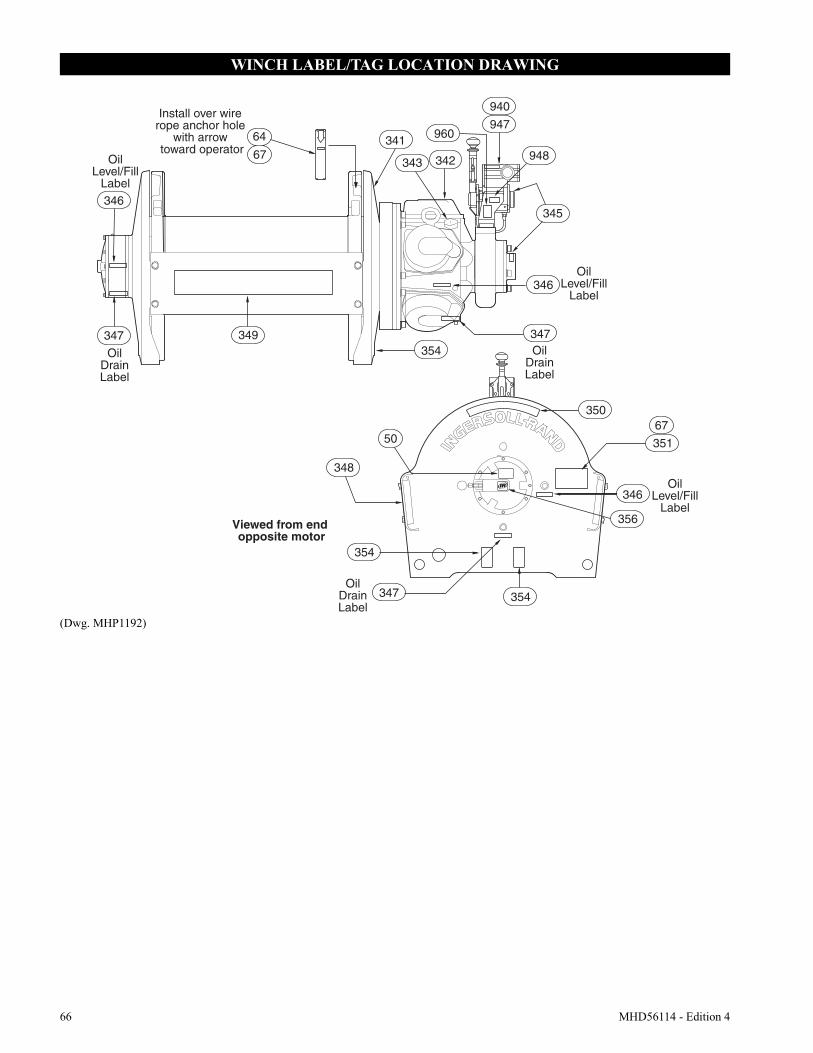
66 MHD56114 - Edition 4
WINCH LABEL/TAG LOCATION DRAWING
(Dwg. MHP1192)
Install over wire rope anchor hole
with arrow toward operator
OilDrainLabel
OilDrainLabel
OilDrainLabel
OilLevel/Fill
Label
OilLevel/Fill
Label
OilLevel/Fill
Label
67
64 341
342343
947
948
960
345
346
347
Viewed from end opposite motor
67350
354
347
356
346
351
346
347 349
348
50
354
940
354
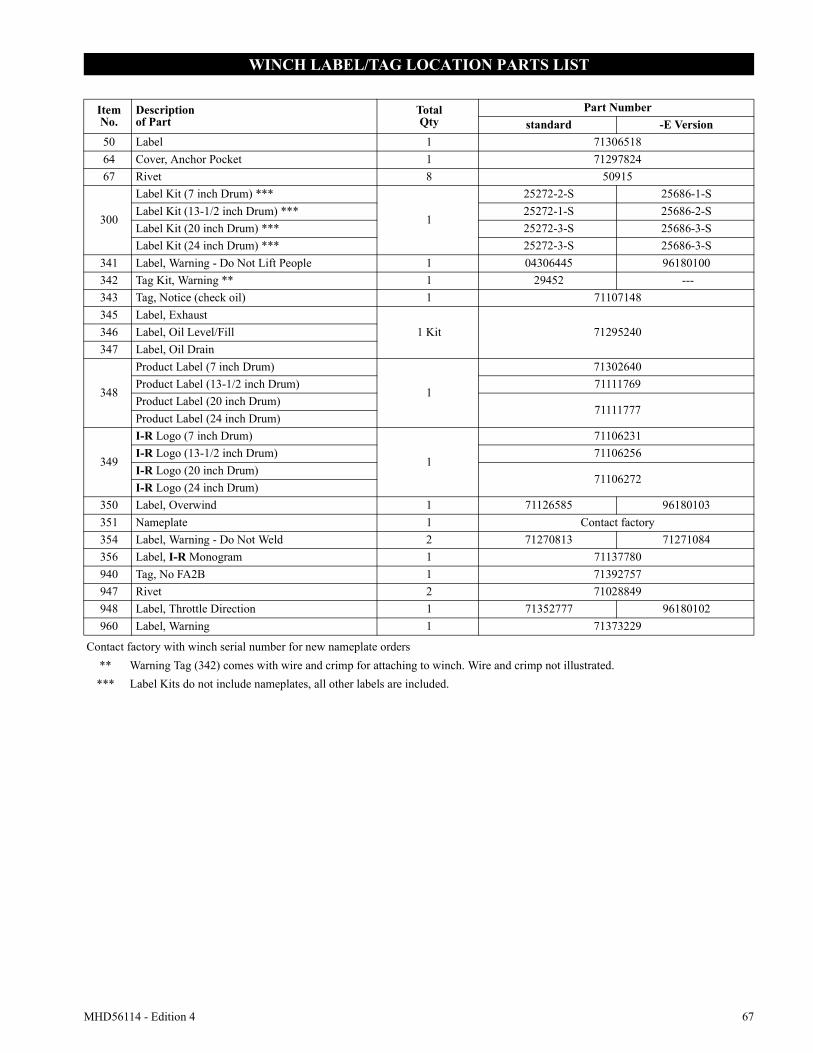
MHD56114 - Edition 4 67
WINCH LABEL/TAG LOCATION PARTS LIST
ItemNo.
Descriptionof Part
TotalQty
Part Numberstandard -E Version
50 Label 1 7130651864 Cover, Anchor Pocket 1 7129782467 Rivet 8 50915
300
Label Kit (7 inch Drum) ***
1
25272-2-S 25686-1-SLabel Kit (13-1/2 inch Drum) *** 25272-1-S 25686-2-SLabel Kit (20 inch Drum) *** 25272-3-S 25686-3-SLabel Kit (24 inch Drum) *** 25272-3-S 25686-3-S
341 Label, Warning - Do Not Lift People 1 04306445 96180100342 Tag Kit, Warning ** 1 29452 ---343 Tag, Notice (check oil) 1 71107148345 Label, Exhaust
1 Kit 71295240346 Label, Oil Level/Fill347 Label, Oil Drain
348
Product Label (7 inch Drum)
1
71302640Product Label (13-1/2 inch Drum) 71111769Product Label (20 inch Drum)
71111777Product Label (24 inch Drum)
349
I-R Logo (7 inch Drum)
1
71106231I-R Logo (13-1/2 inch Drum) 71106256I-R Logo (20 inch Drum)
71106272I-R Logo (24 inch Drum)
350 Label, Overwind 1 71126585 96180103351 Nameplate 1 Contact factory354 Label, Warning - Do Not Weld 2 71270813 71271084356 Label, I-R Monogram 1 71137780940 Tag, No FA2B 1 71392757947 Rivet 2 71028849948 Label, Throttle Direction 1 71352777 96180102960 Label, Warning 1 71373229
Contact factory with winch serial number for new nameplate orders** Warning Tag (342) comes with wire and crimp for attaching to winch. Wire and crimp not illustrated.*** Label Kits do not include nameplates, all other labels are included.
68 MHD56114 - Edition 4
PARTS ORDERING INFORMATION
The use of other than Ingersoll-Rand replacement parts may adversely affect the safe operation and performance of this product.
For your convenience and future reference it is recommended that the following information be recorded.
Model Number _______________________________________
Serial Number ________________________________________
Date Purchased _______________________________________
When ordering replacement parts, please specify the following:1. Complete model number and serial number as it appears on
the nameplate.2. Part number(s) and part description as shown in this manual.3. Quantity required.
The nameplate is located on the winch outboard upright.
NOTICE• Continuing improvement and advancement of design may cause changes to this equipment which are not included in this manual. Manuals are periodically revised to incorporate changes. Always check the manual edition number on the front cover for the latest issue.• Sections of this manual may not apply to your winch.
Return Goods Policy
Ingersoll-Rand will not accept any returned goods for warranty or service work unless prior arrangements have been made and written authorization has been provided from the location where the goods were purchased.
Winches which have been modified without Ingersoll-Rand approval, mishandled or overloaded will not be repaired or replaced under warranty. A printed copy of the warranty which applies to this winch is provided inside the back cover of this manual.
Disposal
When the life of the unit has expired, it is recommended that it be disassembled, degreased and parts separated as to materials so that they may be recycled.
For additional information contact:
Ingersoll-Rand P.O. Box 240462724 Sixth Avenue South Seattle, WA 98124-0046 USAPhone: (206) 624-0466Fax: (206) 624-6265
or
Ingersoll-Rand Douai Operations111, Avenue Roger Salengro 59450 Sin Le Noble, FrancePhone: (33) 3-27-93-08-08Fax: (33) 3-27-93-08-00

MHD56114 - Edition 4 69
SERVICE NOTES

70 MHD56114 - Edition 4
SERVICE NOTES
MHD56114 - Edition 4 71
WARRANTY
HOIST AND WINCH LIMITED WARRANTY
Ingersoll-Rand Company (I-R) warrants to the original user its Hoists and Winches (Products) to be free of defects in material and workmanship for a period of one year from the date of pur-chase. I-R will repair, without cost, any Product found to be defec-tive, including parts and labor charges, or at its option, will replace such Products or refund the purchase price less a reasonable allowance for depreciation, in exchange for the Product. Repairs or replacements are warranted for the remainder of the original warranty period.If any Product proves defective within its original one year war-ranty period, it should be returned to any Authorized Hoist and Winch Service Distributor, transportation prepaid with proof of purchase or warranty card.
This warranty does not apply to Products which I-R has determined to have been misused or abused, improperly maintained by the user, or where the malfunction or defect can be attributed to the use of non-genuine parts.
I-R makes no other warranty, and all implied warranties including any warranty of merchantability or fitness for a par-ticular purpose are limited to the duration of the expressed warranty period as set forth above. I-R’s maximum liability is limited to the purchase price of the Product and in no event shall I-R be liable for any consequential, indirect, incidental, or special damages of any nature rising from the sale or use of the Product, whether based on contract, tort, or otherwise.
Note: Some states do not allow limitations on incidental or conse-quential damages or how long an implied warranty lasts so that the above limitations may not apply to you.
This warranty gives you specific legal rights and you may also have other rights which may vary from state to state.
IMPORTANT NOTICE
It is our policy to promote safe delivery of all orders.
This shipment has been thoroughly checked, packed and inspected before leaving our plant and receipt for it in good condition has been received from the carrier. Any loss or damage which occurs to this shipment while enroute is not due to any action or conduct of the manufacturer.
Visible Loss or DamageIf any of the goods called for on the bill of lading or express receipt are damaged or the quantity is short, do not accept them until the freight or express agent makes an appropriate notation on your freight bill or express receipt.
Concealed Loss or DamageWhen a shipment has been delivered to you in apparent good con-dition, but upon opening the crate or container, loss or damage has taken place while in transit, notify the carrier’s agent immediately.
Damage ClaimsYou must file claims for damage with the carrier. It is the transportation company’s responsibility to reimburse you for repair or replacement of goods damaged in shipment. Claims for loss or damage in shipment must not be deducted from the Ingersoll-Rand invoice, nor should payment of Ingersoll-Rand invoice be withheld awaiting adjustment of such claims as the carrier guarantees safe delivery.
You may return products damaged in shipment to us for repair, which services will be for your account and form your basis for claim against the carrier.
Printed in USA
United States Office Locations International Office Locations
For Order Entry andOrder Status
Ingersoll-RandGlobal LogisticsP.O. Box 618510 Hester DriveWhite House, TN 37188Phone: (615) 474-8665Fax: (615) 672-0854
For Technical Support
Ingersoll-RandP.O. Box 240462724 Sixth Avenue SouthSeattle, WA 98124-0046Phone: (206) 624-0466 or
(866) 273-FAST (3278)Fax: (206) 624-6265
Web Site:www.airwinch.com
Regional Sales Offices
Annandale, NJP.O. Box 9701467 Route 31 SouthAnnandale, NJ 08801Phone: (908) 238-7000Fax: (908) 238-7048
Detroit, MI1872 Enterprise DriveRochester, MI 48309Phone: (248) 293-5700Fax: (248) 293-5800
Offices and distributors in principal cities throughout the world. Contact the nearest Ingersoll-Rand office for the name and address of the distributor in your country or write/fax to:
CanadaNational Sales OfficeRegional WarehouseToronto, Ontario51 Worcester RoadRexdale, OntarioM9W 4K2Phone: (416) 213-4500Fax: (416) 213-4510Order DeskFax: (416) 213-4506
Latin America OperationsIngersoll-Rand730 N.W. 107 AvenueSuite 300, Miami, FL33172-3107 USAPhone: (305) 559-0500Fax: (305) 222-0864
Europe, Middle East and AfricaIngersoll-RandDouai Operations111, avenue Roger Salengro59450 Sin Le Noble, FrancePhone: (33) 3-27-93-08-08Fax: (33) 3-27-93-08-00
Asia Pacific OperationsIngersoll-Rand Ltd.42 Benoi RoadJurong, Singapore 629903Phone: 65-861-1555Fax: 65-862-1373
RussiaIngersoll-RandPresnensky Val19, Moscow, Russia 123557Phone: (7) 095-933-03-24Fax: (7) 095-737-01-48
AustraliaIngersoll-Rand Ltd.Landmark Corporate CenterLevel 2454-472 Nepean HighwayFrankston, Vic 3199AustraliaPhone: 61 3 8781 1600Fax: 61 3 8781 1611