Embed Size (px)
Citation preview

78
Interactive Educational Multimedia, Number 10 (April 2005), pp. 78-89 http://www.ub.edu/multimedia/iem
A multimedia visualization tool for solving
mechanics dynamics problem
S. Manjit Sidhu
College of IT University Tenaga Nasional (UNITEN), Malaysia
S. Ramesh
College of Engineering University Tenaga Nasional (UNITEN), Malaysia
N. Selvanathan
Faculty of Computer Science & IT, Dept. of Software Development, University Malaya, Malaysia
Abstract The objective of this research is to complement and enhanced traditional tutorial teaching and learning by incorporating multimedia technology. In this case study, the development of a PC base virtual experiment for mechanics dynamics problem involving the motion of a projectile that is taught in the second year of the mechanical engineering undergraduate course at University Tenaga Nasional (UNITEN) is described. The developed prototype tool was found to be effective in promoting learning and the outcome of this research revealed that multimedia approach enhanced user understanding of the underlying theory of engineering mechanics, promote interactivity as well as visualization and users are able to solve engineering problem such as motion of a projectile quickly and efficiently. Keywords Engineering, multimedia, interactivity, motion

79
Introduction The influence of the computer is best seen in its multimedia configuration which includes an integration of multiple media elements such as text, graphics, images, audio, video and animation into a coherent learning environment, which in turn transform student learning and problem solving approach (Janson, 1992; Entwistle et al., 1992). Previous studies have shown that traditional learning (classroom teaching) could not engage the learners in visualization tasks and perform virtual experiments (Cairncross and Mannion, 2000). In contrast, multimedia-learning aids have the potential to promote interactivity through its wide range of graphical environments. Additionally, the learner could control the rate of delivery and sequencing of the material being presented, i.e. the learner can learn at his/her own pace without loosing interest in the subject matter. The present study discussed pertinent issues of a multimedia PC based engineering tool that has been developed to solve engineering mechanics dynamics problem involving the motion of a projectile. Our past research has led to the implementation of structured two dimensional (2D) environment that enhanced visualization coupled with real-time motion by integrating 2D animations with multimedia technology. This problem-solving environment has been extended to 2D virtual worlds where the user could freely explore and learn by discovery. Objectives The long-term objective of this study is to develop a realistic 2D and 3D virtual problem-solving environment where a user could learn by discovery and gain better knowledge by doing meaningful tasks. Our present research aimed to define new patterns of interactions by adding interactivity to realistic 2D environment. It is believed that interactivity and providing the virtual environment the capability to adopt coaching and feedback could significantly accelerate the learning curve of users. Virtual Environments Experience through practice by doing is extremely important in the development of basic and advanced skills, particularly in engineering, where the user needs to practice solving a wide range of problems and handle different equations and theories. A highly interactive virtual environment encourages the user to explore complex relationships and increases the development of advanced skills through self-motivated discovery activities (Manjit et al., 2003a). Coach Based Virtual Learning Environments

80
In general, most multimedia-based learning tools does not support learning by discovery but instead provide the basic capabilities for learning-by-doing. Adding interactivity by integrating multiple media elements such as audio, video, image and motion could provide the dynamic assessment, coaching, and feedback capabilities that are essential for positive learning. Some useful learning by doing approach for mechanical engineering problem solving module that has a coach-based virtual learning environment incorporated is presented in Table 1. The main interface of the engineering tool is shown in Fig. 1 and Fig. 2, which highlights the configuration, interface and problem solving steps environment, developed using a variety of multimedia authoring software. In addition, Table. 2 provide further description about each of the interfaces in the mechanics dynamics tool environment presented in Fig. 2.
Learning by Doing Approach
User Activities Coach Virtual Learning Environment
Interaction The user interacts and observes meaningful tasks, e.g. the motion of a rider jumping of a platform.
• Animated video files are integrated with audio files and graphics.
• During the motion, the question is read out to the user.
Steps & Solutions A sequence of steps and solutions of the problem is presented to the user. The user moves forward to the next step or back to the previous step or solution.
• Animated page showing steps and solutions are created and integrated with the tool.
• The tool guides the user to manage the sequence of steps the user should perform to solve the problem and control the 2D animated mechanisms i.e. play, stop, reset and pause.
Simulations The user experiences a problem-solving environment in a virtual manner through the accumulation of his actions and the behavior of the animated mechanisms in a 2D environment.
• The simulations are integrated with 2D graphics that are embedded with audio files.
• The tool manages the state of the 2D animated mechanisms and the user’s interactions.
• The tool further provides graph for users to view data and interpret in a pictorial form.
Table 1. Learning by doing approach with a coach-based virtual learning environment.

81
Fig. 1. Main interface screen snap shot of the mechanics dynamics tool.
Fig. 2. Configuration, interface and problem solving steps environment.

82
Interface Number
Interface Origin Description
1. Macromedia Director
• A brief objective of the experiment is displayed.
2. Macromedia Flash
• An example of a problem in mechanics dynamics engineering is presented.
3. Macromedia Flash
• The given problem is shown and solved on screen in multiple media formats i.e. color, graphics, animations and sound.
• User can interact and control the delivery of the information being presented.
4. Macromedia Flash
• As each page is constructed, the steps in solving the problem is displayed and manipulated with several elements such as text, equations, graphics, audio, and animations.
5. Macromedia Flash
• The solutions are displayed and manipulated with several elements such as text, equations, graphics, audio, and animations.
• Pre-determined graph is included to inform users of the problem status, etc.
6. Macromedia Authorware
• The exercises are design in such a way that the users must interact with the system.
• The user can repeat as many times required until the correct answer is obtained.
7. Macromedia Director
• The help button can be activated to display the user interface information.
8. Macromedia Flash, Microsoft
Windows
• A useful database and search engine are included to store important keywords and meanings.
• A calculator can be called up on the screen to do quick calculations.
• The notepad can be used to type and store brief useful notes that can be printed, saved and retrieved at a later stage.
Table 2. Description of the interfaces employed in the developed tool environment.

83
Multimedia Fundamentals Animations are always used in engineering multimedia visualization tools to represent all kinds of actions, such as object movement, links, pistons, crankshaft, etc. Furthermore multimedia can be used to deliver information in multiple formats i.e. (text, image, animation, audio and video). The delivery of such information, the organization in which it is delivered, and the timing of that delivery can be controlled by the user thus allows the user to engage and interact with the material being presented (Cairncross and Mannion, 2000; Manjit et al., 2003b). This is certainly an added advantage to slow learners. The educational benefits offered by multimedia technology include the ability to take users into environments otherwise inaccessible by conventional means, the high memory retention of experience as opposed to still observation and the ability to reach out to visually oriented learners (Manjit et al., 2003c & 2003d). For example, in mechanical engineering studies there is a need for engineering students to be able to visualize, for example the upper body of a crash dummy where the student is first required to draw a free body diagram and kinetic diagram to illustrate the position when the dummy is rotated at certain angle. Since real experiments of this sort maybe costly and time consuming, it is preferable to imitate and use two-dimensional models that can be developed using authoring software. Solving Engineering Problem using Multimedia Approach The engineering visualization tool implemented and presented in this paper is used to illustrate a 2D virtual environment to allow users to understand as well as to visualize and ultimately to solve problems pertaining to motion of projectile in mechanics dynamics course. By definition, a projectile has only one force acting upon it, i.e. the weight (W) of the projectile due to the gravitational attraction. All other forces such as wind resistance and the effect of drag are neglected. Thus, the free body diagram of a projectile would show a force W acting downwards.
Our past experiences have shown that many students have difficulty with the concept that the only force acting upon an upwardly moving projectile is W (i.e. W = m × g, where m is the mass of the projectile and g is the acceleration due to gravity, normally taken as 9.81 m/s2). Furthermore, their conception of motion prompts them to think that if an object is moving upward, then there must be an upward force lifting the projectile or if an object is moving upward and rightward, there must be both an upward and rightward force acting on the projectile.
To explain further, lets consider the projectile problem given in Fig. 3. The rider leaves the 30o platform with an initial velocity (VA) and in the absence of gravity (i.e., supposing that the "gravity switch could be turned off") the rider would then travel in a straight-line path in the direction of motion. The rider would continue in motion at a

84
constant speed (VA) in the same direction of motion provided there is no unbalanced force acting on him. This is the case for an object moving through space in the absence of gravity. However, if now the "gravity switch could be turned on" then upon leaving the platform the rider is treated as a projectile and the rider would be under free-fall. Under this circumstance, gravity pull takes effect and the path of motion of the projectile would no longer be a straight-line motion. In fact, the projectile would travel with a parabolic trajectory as shown in Fig. 4. As such, the downward force due to gravity effect, i.e. W, will act upon the rider to cause a vertical motion having a downward acceleration of ay = −9.81 m/s2 (the negative sign indicate that the motion is downward). The track for this racing event was designed so that riders jump off the platform at 30º, from a height of 1 m. During a race it was observed that the rider remained in mid air for 1.5 seconds. Determine the speed (VA) at which he was traveling off the slope, and the maximum height (h) he attain. Neglect the size of the bike and the rider.
Fig. 3. Typical projectile problem in mechanics dynamics tool.
Fig. 4. Motion of a projectile. The presence of gravity, however does not affect the horizontal motion of the projectile. The projectile still moves the same horizontal distance in each second of travel as it did when the "gravity switch was turned off." Since, the force due to gravity (W) is a vertical force acting in the y-direction, it does not affect the horizontal motion in the x-direction. According to Newton’s second law of motion, since there is no unbalance force acting on the projectile in the x-direction, then the projectile will not experience acceleration in the x-direction and the horizontal component of acceleration i.e. ax = 0. As such, the projectile moves with a constant horizontal velocity in the x-direction (i.e. Vx = constant) throughout the flight.
C C V
30º1
h
R
y
xA B
85
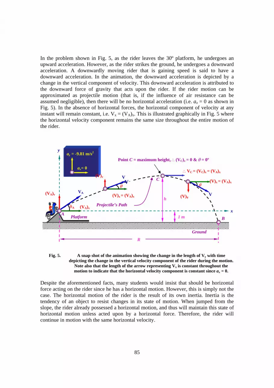
In the problem shown in Fig. 5, as the rider leaves the 30º platform, he undergoes an upward acceleration. However, as the rider strikes the ground, he undergoes a downward acceleration. A downwardly moving rider that is gaining speed is said to have a downward acceleration. In the animation, the downward acceleration is depicted by a change in the vertical component of velocity. This downward acceleration is attributed to the downward force of gravity that acts upon the rider. If the rider motion can be approximated as projectile motion (that is, if the influence of air resistance can be assumed negligible), then there will be no horizontal acceleration (i.e. ax = 0 as shown in Fig. 5). In the absence of horizontal forces, the horizontal component of velocity at any instant will remain constant, i.e. Vx = (VA)x. This is illustrated graphically in Fig. 5 where the horizontal velocity component remains the same size throughout the entire motion of the rider.
Fig. 5. A snap shot of the animation showing the change in the length of Vy with time
depicting the change in the vertical velocity component of the rider during the motion. Note also that the length of the arrow representing Vx is constant throughout the motion to indicate that the horizontal velocity component is constant since ax = 0.
Despite the aforementioned facts, many students would insist that should be horizontal force acting on the rider since he has a horizontal motion. However, this is simply not the case. The horizontal motion of the rider is the result of its own inertia. Inertia is the tendency of an object to resist changes in its state of motion. When jumped from the slope, the rider already possessed a horizontal motion, and thus will maintain this state of horizontal motion unless acted upon by a horizontal force. Therefore, the rider will continue in motion with the same horizontal velocity.
ay = -9.81 m/s2
ax= 0
θ
(V)y
(V)x = (VA)x
V
Ground
y
x
R
B
Point C = maximum height, ∴(VC)y = 0 & θ = 0º
h
1 m
C
∴VC = (VC)x = (VA)x
(VA)y VA
(VA)x
A Platform
θA Projectile’s Path
θV
(V)y
(V)x = (VA)x
V
86
In the conventional method this sort of problems are usually presented to the student as a combination of schematic diagrams and text descriptions. The user/student must immediately apply learned knowledge in order to form an internal model of what the problem means. In addition, in mechanical engineering, the shapes and lines that make up the schematic diagram have very specific engineering meanings. Furthermore, the words accompanying the diagram normally provide additional hints to the problem in question and the user is expected to understand this before applying the appropriate theories in solving the question (Manjit et al., 2003a). On the contrary, with multimedia technology, such information and theories could be explained clearly through various media, which is not possible via conventional method of classroom teaching. The key benefits that users could gained by using the multimedia tool to study the motion of projectile in Fig. 3 are summarized as follows: • The user could see the motion of the projectile at any instant or over a period of time. • The velocity components (i.e. Vx and Vy) at any instant could be analyzed. This is
clearly illustrated in Fig. 5. For example, when time t = 0, the rider is at the start point A on the slope of the platform. At this instant, the rider is moving with a velocity of VA measured at an angle of 30º from the x-axis. In the analysis, the velocity VA can be represented by its components, i.e. (VA)y measured along the y-axis and (VA)x measured along the x-axis. Since the motion of the projectile at A is known, point A is taken as the reference point and the origin of the x-y axes is located at A.
• Enhanced visualization and understanding of the problem. The trace of the path taken
by the rider can be visualized in step-by-step manner as shown in Fig. 6. The user can then observe that the rider has taken a parabolic path, and as such is treated as a projectile motion. As the rider moves in a parabolic trajectory after leaving the platform, the velocity (V) of the rider changes with time and this is illustrated by the change in the length of the arrows representing the velocity components, i.e. (V)x and (V)y. However, since there is no acceleration in the x-direction (i.e. ax = 0), the horizontal component of velocity (Vx) will always be the same as the initial (VA)x. This is shown in the tool by keeping the length Vx equal to (VA)x. To explain further on the theory, during the motion the user is narrated to reinforce learning and understanding. When the rider reached the maximum height at point C, the user can observe that at this instant, (VC)y = 0 and thus the velocity of the rider at C will be VC = (VC)x = (VA)x.
• Promote learning. The incorporation of multimedia technology in this tool could give
a better understanding of the underlying projectile theory i.e. projectile travel with a parabolic trajectory due to the fact that the downward force of gravity accelerates the rider downward from his otherwise straight-line, gravity-free trajectory. This downward force and acceleration results in a downward displacement from the position that the object would be if there were no gravity. The force of gravity does

87
not affect the horizontal component of velocity; a projectile maintains a constant horizontal velocity since there are no horizontal forces acting upon it as clearly illustrated in Fig. 5. For slow learner, the motion of the projectile can be replay as many time necessary and in any order until the user understands the underlying principles.
• In addition, animated graphs could be shown to interpret the velocity (V) versus time
(t) and distance (R) versus time (t) simultaneously of the projectile motion from t = 0 (point A) to t = 1.5 s (point B) as shown in Fig. 7.
Motion of the rider Time interval
t = 0
t = 1.5 s
Fig. 6. Multimedia animation showing the sequence of motion of the rider with respect to
time.

88
Fig. 7. Animated graphs describing the motion of the rider with respect to time. Conclusions Engineering education is an area that holds great interest and potential for virtual engineering tool developers. One reason for this is the ability of experiential learning. The multimedia interactive tool presented in this paper has achieved its objectives, as users were able to describe the position, velocity and acceleration as two-dimensional vectors, recognize two-dimensional projectile motion as simultaneous one-dimensional motion in two directions. Users were able to apply the relevant mechanics theories and kinematics equations to solve projectile motion. Furthermore, users could retained more information through interacting with the multimedia tools then they do from reading books and lectures. The study has shown that multimedia technology is a powerful learning aid that could help learners/users to understand the underlying mechanics principles, visualize the motion of projectile in a dynamic manner and more importantly, to promote deep learning. The interactivity that was incorporated in the multimedia tool allowed users to manage and control the delivery of the material and act as a guide in problem solving. The potential benefits offered by effective virtual learning environment and the approach of learning by doing was identified and discussed. Further work is in progress to develop and implement realistic 2D and 3D virtual learning environments where users could learn by discovery and gain better understanding of the various theories pertaining to mechanical engineering. Our initial step of incorporating multimedia technology in virtual learning environment has enabled the understanding of the process and challenges involved in developing a virtual learning environment.

89
Acknowledgements The authors would like to express their gratitude to UNITEN and University Malaya for the support provided. References Cairncross S and Mannion M. (2000). “Interactive Multimedia and Learning: Realizing
the Benefits”. Innovations in Education and Teaching International, ISSN 1470-3297 © Taylor & Francis Ltd, pp. 153-164.
Entwistle, N., Thomson. S. and Tait, H. (1992). Guidelines for Promoting Effective
Learning in Higher Education, Technical Report, Centre for Research on Learning and Instruction, University of Edinburgh.
Janson, J. L. (1992). Computer-based training helps firms trim budgets. PC Week. pp. 90-
93. Manjit Sidhu, S. Ramesh, S. and Selvanathan, N. (2003a). “Using Multimedia To
Minimize Computational Effort in Engineering”. Proceedings of the Malaysian Scientific & Technology Congress (MSTC) pp. 811-815.
Manjit Sidhu, S., Selvanathan, S. and Ramesh, S. (2003b). “The Role of Multimedia in
Engineering Courseware”. The 32nd International Conference on Computers and Industrial Engineering Proceedings, Ireland U.K, ISBN 1-974653-68-2. Vol. 1. pp. 367-372.
Manjit Sidhu, S., Selvanathan, S., Diljit, S. and Ramesh, S. (2003c). “Visualizing
Mechanics Statics Through Multimedia Interaction”. Proceedings of the World Conference on Science and Technology Education ICASE, pp. 65-71.
Manjit Sidhu, S., Sevanathan, S. and Ramesh, S. (2003d). “Analysis of Engineering
Structures with Multimedia Technology,”. Proceedings of the 2nd Technical Postgraduate Symposium, University Malaya. ISBN 983-100-197-4 pp. 662-666.


