Embed Size (px)
Citation preview

IEEE TRANSACTIONS ON POWER ELECTRONICS, VOL. 21, NO. 4, JULY 2006 985
A Novel DSP-Based Current-Controlled PWMStrategy for Single Phase Grid Connected InvertersHossein Madadi Kojabadi, Bin Yu, Idris A. Gadoura, Member, IEEE, Liuchen Chang, Senior Member, IEEE,
and Mohsen Ghribi
Abstract—The three major approaches for current-regulated in-verters are ramp comparison, hysteresis control, and predictivecurrent control. From these three, predictive current control offersthe potential for achieving more precise current control with min-imum distortion and harmonic noise. But, the predictive method isdifficult to implement and needs more computational burden. Thetraditional predictive current controller has a poor performanceunder component parameter variations, and is less robust to filtersinductance mismatch. A robust predictive current control strategywas proposed and studied. Both simulations and experimental re-sults show that the proposed method is much more robust to pa-rameter mismatch than the traditional one.
Index Terms—Grid connected inverter, predictive control, pulsewidth modulated (PWM), robust control, single phase.
I. INTRODUCTION
THE three major techniques used for regulating the outputcurrent of a voltage source inverter (VSI) are hysteresis,
ramp comparison, and predictive current control [1]. Hysteresiscurrent controllers, presented in [2], utilize hysteresis in com-paring load currents to the references. Hysteresis current con-trollers have the advantage of simplicity and robustness, but theconverters’ switching frequency largely depends on the load pa-rameters and consequently the load current harmonics ripple isnot optimal. Improved hysteresis control strategies were pro-posed, including those of Bose in [3] and Yao and Holmes in[4] which presented the variable-hysteresis-band current con-trol technique. This control method, where the band is modu-lated with the system parameters, maintains a nearly constantswitching frequency. However, its current ripple is still not op-timal. Pan proposed the switch status dependent inner boundcurrent control strategy [5], where an adaptive inner bound ismodulated to reduce switching frequency while maintaining thecurrent error within a specified bound. Ramp comparison con-trol using a PI regulator has a long history of use, but has thedisadvantages of a steady state phase error between referencecurrent and the output current, and also requires accurate tuningto suit load parameters [1].
Manuscript received December 14, 2004; revised September 9, 2005. Rec-ommended by Associate Editor J. Espinoza.
H. M. Kojabadi is with the Department of Electrical Engineering, SahandUniversity of Technology, Tabriz 51335/1996 Iran (e-mail: [email protected]).
B. Yu, I. A. Gadoura, and L. Chang are with the Department of Electrical andComputer Engineering, University of New Brunswick, Fredericton, NB E3B5A3, Canada (e-mail: [email protected]; [email protected]; [email protected]).
M. Ghribi is with the Faculty of Engineering, Universite de Moncton,Moncton, NB E1A 3E9, Canada (e-mail: [email protected]).
Digital Object Identifier 10.1109/TPEL.2006.876851
Predictive controllers calculate the inverter voltages requiredto force the measured currents to follow the reference current[6], [7]. This method offers the potential for achieving moreprecise current control with minimum distortion and harmonicnoise, however, it needs more calculations and requires a goodknowledge of the system parameters. Thanks to the availabilityof powerful, low-cost digital signal processors (DSP)-basedmicrocontrollers, the implementation of predictive strategiesinto digital controllers has been of particular interest in recentstudies. In [6] and [7], the digital predictive current controllersfor single-phase and three-phase voltage-source inverters areproposed. This method fully compensates for the computa-tional and sampling delays errors but the controller has a poorrobustness in real system. The predictive controllers needgood knowledge of the system parameters. If there are modelmismatch in the control system, the mismatch will influencethe control accuracy. In [9], the fuzzy logic controller has beenapplied for single-phase grid connected inverters. Even thoughfuzzy logic control provides robust performance under param-eter and load disturbances, its real time implementation requiresfast microcontrollers. Meanwhile, the authors have providedneither experimental results of their proposed fuzzy logic-basedpredictive current control nor the THD values of inverter outputcurrent. Bode, et al. [10] have proposed a new predictive currentregulation algorithm for single- and three-phase grid connectedinverters. In their paper, they proposed that, instead of zero, thetargeted current error at the end of the period is made equalto half the difference of the previous two current errors. Theexisting predictive current controller by Holmes and Martin [7]had proposed that the target of the controller is making the loadcurrent at the sampling point 1 equal to the referencecurrent value at the end of the switching period [ 1],
1 . In other words, in [7] and [12] the targeted current in1 is made equal to reference current at 1 . The stability
margin for any parameter mismatch in [10] has significantlybeen improved in comparison to methods that are based ondeadbeat algorithm [7], [11], [12]. But their proposed methodis just stable for a margin of 50% mismatch in filter inductance.Experimental results show that the system with more than a50% mismatch in load (or filter) inductance moves the polesout of the unit circle and so, the system becomes unstable.
The authors propose a robust digital predictive current con-troller for grid connected single phase inverters. Simulation andexperimental results demonstrate the superiority of the proposedmethod over existing methods. The experimental results showthat the inverter with the robust predictive current controller hasbetter robustness to parameters mismatch than the inverter withthe traditional predictive current controller. Later, the model
0885-8993/$20.00 © 2006 IEEE

986 IEEE TRANSACTIONS ON POWER ELECTRONICS, VOL. 21, NO. 4, JULY 2006
Fig. 1. Single-phase grid-connected full bridge voltage source inverter.
TABLE ISINGLE PHASE GRID CONNECTED INVERTER’S OPERATIONAL MODES
mismatch influence on two predictive controllers will be dis-cussed. The resultant current controller achieves minimum cur-rent error, constant switching frequency, robustness to modelparameters mismatch, and is simple enough for digital imple-mentation in a DSP microcontroller.
II. ROBUST PREDICTIVE CURRENT-CONTROLLED
PWM STRATEGY
A. Signal-Phase Full-Bridge Voltage Source Inverter
The single-phase full bridge voltage source inverter topologyis shown in Fig. 1. It is composed of a dc voltage source, fourpower switches and a filter inductor. The full-bridge inverter’soperation can be divided into four modes: two modes in posi-tive load current period and two modes in negative load currentperiod. Table I shows the single-phase grid connected inverter’soperational modes.
B. Current Controller Strategies of Voltage Source Inverter
For inverter-based distributed generation systems (DG),the inverters are connected to the existing grid, therefore, thevoltage cannot be controlled. The power quality is definedby the current quality. Pulse width modulation (PWM) is themost popular control technique in voltage-source inverters.As compared to the open loop voltage PWM converters, thecurrent-controlled PWM has several advantages. One of theadvantages is control of instantaneous current waveform andhigh accuracy. This advantage can control precisely the currentinjected into grid with low distortion and harmonic noise.
The strategies of current controllers can be classified as: rampcomparison controllers, hysteresis controllers, and predictivecontrollers. The ramp comparison controller compares the cur-rent errors to triangle wave to generate the inverter firing signals.The hysteresis controllers utilize some type of hysteresis in thecomparison of the currents to the current reference. The predic-tive controllers calculate the inverter voltages required to forcethe measured currents to follow the current reference.
C. Traditional Predictive Current Controller
In [7], Holmes and Martin have proposed an algorithm for di-rectly implementing a predictive current controller in a micro-processor for load situation where the load voltage is known.The proposed method compensates the errors caused by dig-ital sampling and computing delays. The algorithm uses the re-sults of previous switching cycles to estimate both the next gridvoltage and load current. Fig. 1 illustrates the circuit diagram ofsingle-phase grid-connected inverter. The inverter load current
is decided by following differential equation:
(1)
where is the grid voltage, is the inverter’s outputvoltage, and is the filter’s inductance in mH.
Assuming that the inverter is operating with a constantswitching frequency, the switching period is a constant value,
. In the switching period 1 , (1) can be writtenin a discrete form, as
(2)
where are the average inverter outputvoltage and average grid voltage over the switching period
1 , respectively, and 1 are themeasured load currents at the sampling point of 1 and ,respectively. The timing schematic is shown in Fig. 2.
The target of the controller is making the load current at thesampling point 1 equal to the reference currentvalue at the end of the switching period 1 1 .So the predictive average output voltage turns to be
(3)
The practical implementation will require computational timeto solve for the . As illustrated in Fig. 2, the tradi-tional predictive algorithm does the computation in the previousswitching period [ 1 ]. This means that the measured valuesof current, 1 , and grid voltage, 1 , are onlyavailable up to 1 before the calculation proceed. The con-troller will predict the and and calculate thedemand inverter output voltage . Then, the controllercontrols the four switches at controlling point of 1 .
To predict, , the average grid voltage overswitching period 1 , assume that the change of gridvoltage over the switching period is linear and the grid voltagechange over the switching period 1 is equal to thechange of the switching period 1 . Then, canbe estimated from previously measured voltage using a simplelinear extrapolation
(4)

KOJABADI et al.: NOVEL DSP-BASED CURRENT-CONTROLLED PWM STRATEGY 987
Fig. 2. Timing schematic of switching periods and sampling points.
Fig. 3. Timing schematic of sampling point and controlling point.
can be estimated by adding the predicted current changeduring the switching period 1 to the measured currentat time 1
(5)
By substituting (4) and (5) into (3) the demand average outputvoltage applied in the switching period 1 , is
(6)
D. Robust Predictive Current Controller
Laboratory tests show that the traditional predictive currentalgorithm has poor robustness to model parameters mismatch,such as filter’s inductance. The error between the actual andmodel filter inductance will cause the inverter output current tooscillate.
A robust predictive current controller with better robustnessto parameters mismatch is proposed. As mentioned before, thepredictive average output voltage is
The traditional predictive algorithm does the computation inthe previous switching period to compensate the errors intro-duced by sampling and computation delays. In experiments, the
delays can be measured. For TMS320-2407A the delays is arearound 10 s. Fig. 3 illustrates the delays as total delay (TD).Compared to a 16.6-ms cycle period of a 60-Hz grid voltageand current frequency, 10 s is so negligible that one can as-sume the sampled grid voltage and load current are unchangedin this period.
As illustrated in Fig. 3, the sampling point is set just aheadof controlling point by the period of the TD. With the aboveassumption, the measured values of current and gridvoltage are available up to instant before the calcu-lation proceeds to predict the demanded output voltage of theinverter.
To predict , the average grid voltage overswitching period , assume that the change of gridvoltage over the switching period is linear and the grid voltagechange over the switching period 1 is equal to the changeof the switching period 1 . Then, can beobtained from the measured grid voltage, 1 ,as
(7)
Substituting (7) and (5) into (3), the predictive average outputvoltage of the inverter over the switching period 1
(8)

988 IEEE TRANSACTIONS ON POWER ELECTRONICS, VOL. 21, NO. 4, JULY 2006
Fig. 4. Output current waveform of inverter with traditional predictivecontroller.
Fig. 5. Output current waveform of inverter with robust predictive controller.
III. SIMULATION RESULTS
Two current controlled PWM strategies: traditional predictivecurrent controller and robust predictive current controller areverified by the simulation using PSIM software package. For allsimulations, the dc voltage and grid voltage are 400 V and 240 V,respectively, filter inductor is 2 mH, and output power is 10 kW.The simulation results of traditional current predictive controlleris shown in Fig. 4. The switching frequency of IGBTs sets at10 kHz. The current THD is 2.8% at 10 kW. The simulationresults of robust current predictive controller is shown in Fig. 5.The switching frequency of IGBTs sets at 10 kHz. The currentTHD is 2.6% at 10 kW.
Comparing the simulation results of two current controllersconfirm that both algorithms meet the IEEE Standard 1547 re-quirement of THD, which is below 5% [1]. The predictive con-trollers need good knowledge of the system parameters. If thereare model mismatches in the control system, the mismatcheswill influence the control accuracy [8]. In Section V, the in-fluence of model parameters mismatch on two predictive con-trollers will be discussed.
Fig. 6. The 10-kW prototype grid-connected single-phase IGBT inverter.
TABLE IICURRENT THD OF 10-KW PROTOTYPE INVERTER
IV. EXPERIMENTAL RESULTS
The proposed predictive current control strategy is tested on10-kW prototype grid-connected single-phase IGBT inverter.Fig. 6 illustrates the configuration of the inverter. The proto-type IGBT inverter includes a power circuit module, an inter-facing and sensing module, a DSP-based control module, and anIGBT driver module. The input of the inverter is connected to athree-phase generator driven by wind turbine or micro-gas-tur-bine system. The rated input line-line voltage from the generatoris 280 V, corresponding to a dc link voltage of 390 V. The outputof the inverter is connected to the grid. The normal grid voltageis 240 V and grid frequency is 60 Hz. The rated output currentis 42 A. The inverter is equipped with software and hardwareprotections including the over-current of dc link and inverteroutput, the over-temperature of IGBTs, the over-voltage of grid,dc link and generator, the under-voltage of grid and generator,the over-frequency of grid, and the under-frequency of grid.
For all experiments, the grid voltage is 242 V, and filter’s in-ductor is 2 mH. THD of grid voltage is 2.3%. The experimentalresults of the current THD at four different output power levelsare listed in Table II.
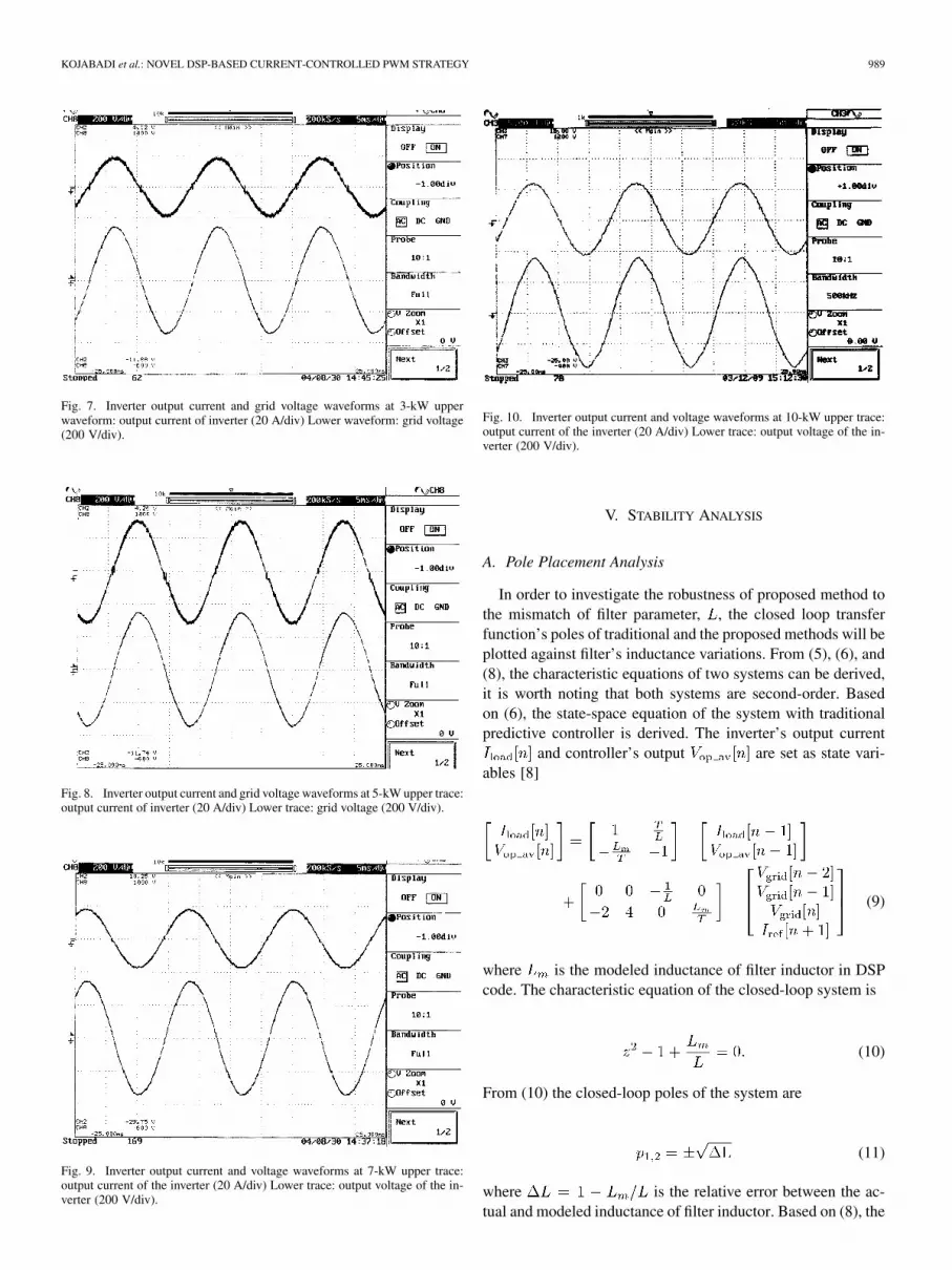
Figs. 7–10 illustrate the experimental waveforms of theinverter output current and grid voltage at four output powerlevels: 3, 5, 7, and 10 kW. The dc link voltage is 400 V. Theexperimental data were sampled by the digital scope. Thesetests confirm the results of Table II that by increasing the outputpower THD of output current reduces. Fig. 7 shows the largerTHD at 3-kW output and Fig. 10 indicates the lowest THD at10-kW output power.
Fig. 8 indicates the output current and grid voltages at 5-kWoutput power. One can recognize that the current THD is re-duced in comparison to Fig. 7 with 3-kW output. Inverter’soutput current and voltage waveforms are shown in Fig. 9 for7–kW output power. THD is much smaller than in case of 3 kW.In Fig. 10, the grid voltage and output current waveforms havebeen shown. The THD of output current is 0.9% thus 2% smallerthan the same inverter with 3-kW output power. By large dcvoltage of dc link the current waveform will be closer to puresinusoidal as one can see from Table II. For 3-kW output the dcvoltage is 360 V with 2.9% THD whereas for 10 kW the dc linkvoltage has been increased to 400 V with 0.95% THD.
KOJABADI et al.: NOVEL DSP-BASED CURRENT-CONTROLLED PWM STRATEGY 989
Fig. 7. Inverter output current and grid voltage waveforms at 3-kW upperwaveform: output current of inverter (20 A/div) Lower waveform: grid voltage(200 V/div).
Fig. 8. Inverter output current and grid voltage waveforms at 5-kW upper trace:output current of inverter (20 A/div) Lower trace: grid voltage (200 V/div).
Fig. 9. Inverter output current and voltage waveforms at 7-kW upper trace:output current of the inverter (20 A/div) Lower trace: output voltage of the in-verter (200 V/div).
Fig. 10. Inverter output current and voltage waveforms at 10-kW upper trace:output current of the inverter (20 A/div) Lower trace: output voltage of the in-verter (200 V/div).
V. STABILITY ANALYSIS
A. Pole Placement Analysis
In order to investigate the robustness of proposed method tothe mismatch of filter parameter, , the closed loop transferfunction’s poles of traditional and the proposed methods will beplotted against filter’s inductance variations. From (5), (6), and(8), the characteristic equations of two systems can be derived,it is worth noting that both systems are second-order. Basedon (6), the state-space equation of the system with traditionalpredictive controller is derived. The inverter’s output current
and controller’s output are set as state vari-ables [8]
(9)
where is the modeled inductance of filter inductor in DSPcode. The characteristic equation of the closed-loop system is
(10)
From (10) the closed-loop poles of the system are
(11)
where is the relative error between the ac-tual and modeled inductance of filter inductor. Based on (8), the

990 IEEE TRANSACTIONS ON POWER ELECTRONICS, VOL. 21, NO. 4, JULY 2006
state-space equation of the system with proposed robust predic-tive controller is derived. Again, the inverter’s output current
and controller’s output are set as state vari-ables [8]
(12)
The characteristic equation of the closed-loop system is
(13)
From (13), the closed-loop poles of the system are
(14)
The relative error between the actual and modeled induc-tance, , will influence the location of closed-loop poles. Thismodel mismatch will influence the transient response character-istics and the stability of the two systems. The relative error ofinductance, , could be positive or negative. The positive rel-ative error implies that the modeled inductance value is smallerthan actual inductance value. The negative relative error im-plies that the modeled inductance value is bigger than actualinductance value. For traditional predictive current controller,the poles of closed-loop systems in -plane are .When relative inductance error is positive, one pole is on posi-tive half real axis and another one is on negative half real axis.When relative inductance error is negative, one pole is on pos-itive half imaginary axis and another one is on negative halfimaginary axis. On the other hand, for robust predictive cur-rent controller, the poles of closed-loop systems in -plane are
0 and . When relative inductance error is posi-tive, one pole is on positive half real axis and another one is atorigin. When relative inductance error is negative, one pole is onnegative half real axis and another one is at the origin. Fig. 11illustrates the closed-loop pole placement of traditional and ro-bust system. From Fig. 11 it is worth noting that with2 the poles will be on or outside the unit circle and, therefore,both systems will be unstable as shown in Figs. 15 and 16. First,the stable range of two systems is discussed with respect to therelative error between the actual and modeled inductance. Thestable criterion of controlled system in -plane is that the polesof closed-loop system are located inside the unit circle. For bothsystems, the stable range of relative error of inductance is
Therefore, the stable range of modeled filter inductance for tra-ditional and robust predictive systems is
Fig. 11. Closed-loop poles with changing of �L for: Upper trace, traditionaland Lower trace, robust systems.
Thus, both systems have the same stable range of modeled filterinductance. But for both positive and negative relative error ofinductance, , the proposed method’s poles will be locatedon origin or real axis. For the traditional one method, the poleswill be located on imaginary axes for negative . In [10],the root locus plots of various predictive current controllers arepresented in -domain. It can be seen that proposed method in[10] and all existing predictive methods based on a deadbeatalgorithm [[7], [11], [12]] are unstable for 1.51.5 ). However, the stability margin shows more significant im-provement in [10] than the methods based on previous deadbeatalgorithm.
B. Robustness Analysis of Two Predictive Methods
In this robustness analysis, a multiplicative-uncertaintymodel is used to represent the uncertainty
where is the perturbed model, is the nominal model, isthe uncertainty model, and is the number of values, i.e.,

KOJABADI et al.: NOVEL DSP-BASED CURRENT-CONTROLLED PWM STRATEGY 991
Fig. 12. Comparison between the 1-norm of relative errors for traditional(solid-line) and proposed systems (dotted-line) Y -axis: the eight-norm of rela-tive error.
Fig. 13. Model mismatch(�L > 0)influence on traditional system.
0.7 , 0.8 , 0.9 , 1.3 , 1.6 , 2 , where is thevalue of output filter inductor.
In order to carry out the preliminary comparison betweenboth systems, their robustness has been examined by checkingthe -norm of the relative errors
(15)
where is the relative error between the nominal model withactual inductance, , and the perturbed model with mod-eled inductance, , and is the frequency range, e.g., 10
10 as shown in Fig. 12. Equation (15) is usually used tomodel the multiplicative-input uncertainty, , which is definedas the upper boundary of all possible , wherefor all is a condition to achieve a robust control design
Fig. 14. Model mismatch (�L > 0) influence on proposed system.
From Fig. 12, it is clear that the proposed system producessmaller than the traditional system.
This indicates that the uncertainty of the robust predictivecontrol design has less influence on the overall system than thetraditional predictive control design, especially in low frequencyregion.
C. Robustness Comparison of Two Predictive Algorithms byExperimental Tests
To confirm the conclusion in Section V-A, the modeled filterinductance, , is set to four different values 1.3
1.6 2.0 in the experiments to see the model mis-match influence on two systems. The tests have been done on a10-kW prototype inverter with 2-mH filter inductor. The digitalcontroller implements two predictive algorithms separately. Theoutput power of inverter is set at 3 kW, and dc link voltage was380 V. The predictive average output voltage, , and in-verter output current are monitored in order to compare. Fig. 13illustrates the experimental results of old system with the tra-ditional predictive algorithm, where the modeled inductance issmaller than the actual inductance. It is noted that the predictiveoutput voltage and load current begin to oscillate when10%. The oscillations are getting more severe when turns
bigger ( 20% and 30%).Fig. 14 illustrates the experimental results of proposed system
with the robust predictive algorithm, where the modeled induc-tance is smaller than the actual inductance. It is seen that thereis no oscillation in predictive output voltage and load current.So the conclusion in Section V-A has been confirmed by ex-perimental results. Fig. 15 illustrates experimental results of thesystem whose controller implements the traditional predictivealgorithm, where modeled inductance is bigger than actual in-ductance. One can note that predictive output voltage and loadcurrent begin to oscillate when 30%. The oscilla-tion turns more obviously when 60%. When
100%, the predictive output voltage and load current oscil-late continuously. This confirms the analysis in previous Sec-tions V-A and V-B that a traditional system turns unstable whenmodel inductance is two times bigger than actual inductance.

992 IEEE TRANSACTIONS ON POWER ELECTRONICS, VOL. 21, NO. 4, JULY 2006
Fig. 15. Model mismatch influence on traditional method, (�L < 0).
Fig. 16. Model mismatch influence on proposed method, (�L < 0).
Fig. 16 illustrates experimental results of a proposed systemwhose controller implements the robust predictive algorithm,where modeled inductance is bigger than actual inductance. Onecan note that predictive output voltage and load current begin tooscillate when 60%. When 100%, the pre-dictive output voltage and load current oscillate continuously.Also, the proposed system turns unstable when model induc-tance is two times bigger than actual inductance. By comparingboth Figs. 15 and 16, it is worth noting that both systems start tooscillate continuously when modeling inductance is two timesbigger than the actual one, but the magnitude of perturbations inthe traditional method is much bigger than the proposed one. Inaddition, for 60%, the proposed method has an accept-able output current waveform with small THD. However, thetraditional method has an unacceptable THD for 30%.Stability results in Figs. 13–16 are verified by the experiments.The waveforms shown are plotted in a MATLAB environment;however, the data has been transferred from a DSP target board.
VI. CONCLUSION
Simulation and experimental results confirm that the pre-dictive current controllers in grid connected inverters provide
better THD value based on IEEE standards. The theoreticalanalysis and experimental results proved that model mismatchof a filter inductor influences the system stability and transientresponse characteristics. For a predictive controller, accuracy ofthe model will affect the controller’s performance dramatically.Comparing two predictive control algorithms, the system thatimplements the proposed algorithm is more robust than thesystem which implements the traditional predictive algorithm.Both traditional and proposed predictive methods provide ac-ceptable 5% value but the proposed method producessmaller than the traditional system. This indicates thatthe uncertainty of the robust predictive control design has lessinfluence on the overall system than the traditional predictivecontrol design, especially in the low frequency region.
REFERENCES
[1] D. M. Brod and D. W. Novotny, “Current control of VSI-PWM in-verters,” IEEE Trans Ind. Appl., vol. IA-2, no. 4, pp. 562–570, Jul./Aug.1985.
[2] A. B. Plunkett, “A current controlled PWM transistor inverted drive,”in Proc. IEEE IAS Annu. Meeting, 1979, pp. 785–792.
[3] B. K. Bose, “An adaptive hysteresis–Band current control technique ofa voltage-fed PWM inverter for machine drive system,” IEEE Trans.Ind. Electron., vol. 37, no. 5, pp. 402–408, Oct. 1990.
[4] Q. Yao and D. G. Holmes, “A simple novel method for variable—Hys-teresis-band current control of a three phase inverter with constantswitching frequency,” in Proc. IEEE Ind. Appl. Meeting, Oct. 1993,pp. 1122–1129.
[5] C. T. Pan, Y. S. Huang, and T. L. Jong, “A constantly sampled currentcontroller with switch status dependent inner bound,” IEEE Trans. Ind.Electron., vol. 50, no. 3, pp. 528–535, Jun. 2003.
[6] J. Holtz and S. Stadtfeld, “A predictive controller for the stator currentvector of AC machines fed from a switched voltage source,” in Proc.Annu. Meeting Int. Power Electron. Conf., 1983, pp. 1665–1675.
[7] D. G. Holmes and D. A Martin, “Implementation of a direct digitalpredictive current controller for single and three phase voltage sourceinverter,” in Proc. Annu. Meeting IEEE Ind. Appl., 1996, pp. 906–913.
[8] B. Yu, “Predictive Current Controlled PWM Strategy for Grid-con-nected Single-Phase Inverter,” M.Sc. thesis, Univ. New Brunswick,Fredericton, NB, Canada, 2004.
[9] S. Premrudeepreechacharn and T. Poapornsawan, “Fuzzy logic con-trol of predictive current control for grid connected single phase in-verter,” in Proc. 28th IEEE Photovolt. Spec. Conf., Sep. 15-22, 2000,pp. 1715–1718.
[10] G. H. Bode, P. C. Loh, M. J. Newman, and D. G. Holmes, “An im-proved robust predictive current regulation algorithm,” in Proc. 5thInt. Conf. Power Electron. Drive Syst. (PEDS’03), 2003, vol. 2, pp.1058–1063.
[11] T. Summers and R. E. Betz, “Dead—Time issues in predictive currentcontrol,” in Proc. 37th IAS Annu. Meeting, 2002, vol. 3, pp. 2086–2093.
[12] O. kukrer, “Discrete time current control of voltage fed three phasePWM inverters,” IEEE Trans. Power Electron., vol. 11, no. 2, pp.260–269, May 1996.
Hossein Madadi Kojabadi received the B.Sc. andM.Sc. degrees (with honors) in electrical engineeringfrom University of Tabriz, Tabriz, Iran, in 1989 and1992, respectively, and the Ph.D. degree in electricalengineering from the University of New Brunswick,Fredericton, NB, Canada, in 2003.
He is currently an Associate Professor at SahandUniversity of Technology, Tabriz. He was Post-Doc.Fellow at the University of New Brunswick andUniversite de Moncton, Moncton, NB, from 2003 to2005. He has published over 30 papers in technical
journals and conference proceedings and two books. His research interestsinclude motor drives, power electronics, electrical machines, renewable energysystems, state estimation, energy conversion, and control and applications.

KOJABADI et al.: NOVEL DSP-BASED CURRENT-CONTROLLED PWM STRATEGY 993
Bin Yu received the B.Sc. degree from Nanjing University of Aeronautics andAstronautics, Nanjing, China, in 1996 and the M.Sc. degree from the Universityof New Brunswick, Fredericton, NB, Canada, in 2004.
His research interests include grid connected inverters, control theory, andpower electronics.
Idris A. Gadoura (S’95–M’03) received the B.Sc.degree in electrical engineering from the Universityof Garyounis, Benghazi, Libya, in 1989 and theM.Sc. degree in electrical engineering and the Lic.Sc. and D.Sc. degrees in control engineering fromthe Helsinki University of Technology, Espoo,Finland, in 1997, 1999, and 2002, respectively.
From 1989 to 1995, he was a Consultant Engineerwith Brown and Root, Ltd. He has been with theControl Engineering Laboratory, Helsinki Universityof Technology, as a Research Scientist from 1998
to 2002. Since 2003, he has been with the University of New Brunswick,Fredericton, NB, Canada, as a Research Associate. His main research inter-ests are system modeling and control design in telecom power supplies andrenewable energy systems applications.
Liuchen Chang (S’87–M’92–SM’99) received theB.S.E.E. degree from Northern Jiaotong University,Beijing, China, in 1982, the M.Sc. degree fromthe China Academy of Railway Sciences (CARS),Beijing, in 1984, and the Ph.D. degree from Queen’sUniversity, London, ON, Canada, in 1991.
From 1984 to 1987, he was at CARS as a Re-searcher on railway traction systems. He is currentlya Professor of electrical and computer engineeringand NSERC Chair in Environmental Design En-gineering at the University of New Brunswick,
Fredericton, NB, Canada. He has published over 90 papers in technical journalsand conference proceedings and two books. His principal research interests andexperience include distributed power generation, renewable energy conversion,power electronic converters and variable-speed drives, analysis and design ofelectrical machines, and finite-element electromagnetic analysis and design.
Dr. Chang is a s Registered Professional Engineer with the Association ofProfessional Engineers and Geoscientists of New Brunswick (APEGNB).
Mohsen Ghribi received the B.Ing. degree inelectrical engineering and the M.Sc. degree inindustral electronics from Université du Québec àTrois-Rivières, Trois-Rivières, QC, Canada, in 1987and 1989, respectively, and the Ph.D. degree fromthe Université Laval, Quebec City, QC, in 1994.
He has been a Professor at École de TechnologieSupérieure, Montréal, QC and the École Polytech-nique de Masuku, Gabon. Since 1997, he has beena Professor in electrical engineering at the Universitéde Moncton, Moncton, NB, Canada. His research in-
terests include ac drives, control systems, and real-time implementation usingDSP.


