Embed Size (px)
Citation preview

Nuclear Instruments and Methods in Physics Research A 696 (2012) 55–65
Contents lists available at SciVerse ScienceDirect
Nuclear Instruments and Methods inPhysics Research A
0168-90
http://d
n Corr
E-m
journal homepage: www.elsevier.com/locate/nima
Accelerator-induced transients in Accelerator Driven Subcritical Reactors
Ali Ahmad n, Benjamin A. Lindley, Geoffrey T. Parks
Department of Engineering, University of Cambridge, Cambridge CB2 1PZ, United Kingdom
a r t i c l e i n f o
Article history:
Received 28 July 2012
Received in revised form
14 August 2012
Accepted 1 September 2012Available online 8 September 2012
Keywords:
Accelerator Driven Subcritical Reactor
Accelerator reliability
Beam interruptions
Pulsed operation
Beam overpower
02/$ - see front matter & 2012 Elsevier B.V. A
x.doi.org/10.1016/j.nima.2012.09.004
esponding author. Tel.: þ44 1223 748245; fa
ail address: [email protected] (A. Ahmad).
a b s t r a c t
Achieving higher particles energies and beam powers have long been the main focus of research in
accelerator technology. Since Accelerator Driven Subcritical Reactors (ADSRs) have become the subject
of increasing interest, accelerator reliability and modes of operation have become important matters
that require further research and development in order to accommodate the engineering and economic
needs of ADSRs. This paper focuses on neutronic and thermo-mechanical analyses of accelerator-
induced transients in an ADSR. Such transients fall into three main categories: beam interruptions
(trips), pulsed-beam operation, and beam overpower. The concept of a multiple-target ADSR is shown
to increase system reliability and to mitigate the negative effects of beam interruptions, such as
thermal cyclic fatigue in the fuel cladding and the huge financial cost of total power loss. This work also
demonstrates the effectiveness of the temperature-to-reactivity feedback mechanisms in ADSRs. A
comparison of shutdown mechanisms using control rods and beam cut-off highlights the intrinsic
safety features of ADSRs. It is evident that the presence of control rods is crucial in an industrial-scale
ADSR. This paper also proposes a method to monitor core reactivity online using the repetitive pattern
of beam current fluctuations in a pulsed-beam operation mode. Results were produced using PTS-ADS,
a computer code developed specifically to study the dynamic neutronic and thermal responses to beam
transients in subcritical reactor systems.
& 2012 Elsevier B.V. All rights reserved.
1. Introduction
Accelerator Driven Subcritical Reactors (ADSRs) have recentlygained increased interest as a promising nuclear reactor technol-ogy that offers inherent safety, sustainability and economiccompetitiveness. The concept of an ADSR is based on the couplingof a particle accelerator that delivers a beam of protons of� 1 GeV energy to initiate spallation reactions in a heavy metaltarget and a subcritical nuclear reactor fed by the spallationneutrons. This coupling facilitates better control of reactor opera-tion. Fig. 1 shows a conceptual representation of an ADSR and itsthree main components: accelerator, spallation target and sub-critical core surrounding the target.
A major safety feature of ADSRs is the fact that the reactoroperates subcritically and is therefore not able to sustain a fissionchain reaction without the external supply of neutrons providedby spallation. The reactor system can be shutdown by simplycutting off the beam current.
ADSRs can potentially utilise a variety of nuclear fuels basedon uranium, plutonium or thorium. Furthermore, due to theirintrinsic subcriticality, ADSRs can also accommodate fuel forms,
ll rights reserved.
x: þ44 1223 332662.
such as mixed oxide (MOX) fuel, with lower delayed neutronfractions [24]. MOX fuel is favourable in countries, such as the UKand France, that have adopted or could readily adopt a closednuclear fuel cycle.
In most current ADSR proposals, the subcritical core is oper-ated with a fast neutron energy spectrum; in other words, unlikecurrent power generating nuclear reactors, there is no moderatorpresent to slow the neutrons produced by fission (or spallation)down to thermal energies. Operation in the fast spectrum isbelieved to offer an ADSR better neutron economy and enhancedsafety [5].
The sustainability benefits of ADSRs are closely related to thepossible exploitation of the thorium fuel cycle in them [27].Thorium is three to four times more abundant in nature thanuranium and under certain circumstances produces fewer minoractinides [16].
For the work presented in this paper, the core and fuel pingeometries and the physical properties of the fuel, cladding andcoolant were taken from the XADS design [6,7]. The values of theprincipal XADS core and fuel design specifications are detailedin Table 1.
This paper aims to provide a neutronic analysis of accelerator-induced transients in ADSRs. For the concept of an accelerator–reactor hybrid system to advance, accelerator technology mustachieve certain operational criteria that mainly target improved
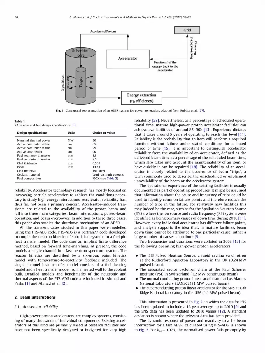
Fig. 1. Conceptual representation of an ADSR system for power generation, adapted from Rubbia et al. [27].
Table 1XADS core and fuel design specifications [6].
Design specifications Units Choice or value
Nominal thermal power MW 80
Active core outer radius cm 85
Active core inner radius cm 29
Active core height cm 90
Fuel rod inner diameter mm 1.8
Fuel rod outer diameter mm 8.5
Clad thickness mm 0.565
Pitch mm 13.43
Clad material T91 steel
Coolant material Lead–bismuth eutectic
Fuel composition MOX (see Table 2)
A. Ahmad et al. / Nuclear Instruments and Methods in Physics Research A 696 (2012) 55–6556
reliability. Accelerator technology research has mostly focused onincreasing particle acceleration to achieve the conditions neces-sary to study high energy interactions. Accelerator reliability has,thus far, not been a primary concern. Accelerator-induced tran-sients are related to the availability of the proton beam andfall into three main categories: beam interruptions, pulsed-beamoperation, and beam overpower. In addition to these three cases,this paper also studies the shutdown mechanism of an ADSR.
All the transient cases studied in this paper were modelledusing the PTS-ADS code. PTS-ADS is a Fortran77 code developedto couple the neutron kinetics of subcritical systems to a fuel pinheat transfer model. The code uses an implicit finite differencemethod, based on forward time-marching. At present, the codemodels a single channel in a fast neutron spectrum reactor. Thereactor kinetics are described by a six-group point kineticsmodel with temperature-to-reactivity feedback included. Thesingle channel heat transfer model consists of a fuel heatingmodel and a heat transfer model from a heated wall to the coolantbulk. Detailed models and benchmarks of the neutronic andthermal aspects of the PTS-ADS code are included in Ahmad andParks [1] and Ahmad et al. [2].
2. Beam interruptions
2.1. Accelerator reliability
High-power proton accelerators are complex systems, consist-ing of many thousands of individual components. Existing accel-erators of this kind are primarily based at research facilities andhave not been specifically designed or budgeted for very high
reliability [28]. Nevertheless, as a percentage of scheduled opera-tional time, mature high-power proton accelerator facilities canachieve availabilities of around 85–90% [13]. Experience dictatesthat it takes around 5 years of operating to reach this level [11].Reliability is the probability that an item will perform a requiredfunction without failure under stated conditions for a statedperiod of time [15]. It is important to distinguish acceleratorreliability from the availability of an accelerator, defined as thedelivered beam time as a percentage of the scheduled beam time,which also takes into account the maintainability of an item, orhow quickly it can be repaired [18]. The reliability of an accel-erator is closely related to the occurrence of beam ‘‘trips’’, aterm commonly used to describe the unscheduled or unplannedunavailability of the beam or the accelerator system.
The operational experience of the existing facilities is usuallydocumented as part of operating procedures. It might be assumedthat information about the cause and frequency of trips could beused to identify common failure points and therefore reduce thenumber of trips in the future. For relatively new facilities thismay indeed be the case, such as for the Spallation Neutron Source(SNS), where the ion source and radio frequency (RF) system wereidentified as being primary causes of down time during 2010 [11].However, every individual accelerator has different failure points,and analysis supports the idea that, in mature facilities, beamdown time cannot be attributed to one particular cause, rather alarge number of causes contribute [9].
Trip frequencies and durations were collated in 2008 [13] forthe following operating high-power proton accelerators:
�
The ISIS Pulsed Neutron Source, a rapid cycling synchrotronat the Rutherford Appleton Laboratory in the UK (0.24 MWpulsed beam). � The separated sector cyclotron chain at the Paul ScherrerInstitute (PSI) in Switzerland (1.2 MW continuous beam).
� The normal conducting proton linear accelerator at Los AlamosNational Laboratory (LANSCE) (1 MW pulsed beam).
� The superconducting proton linear accelerator for the SNS at OakRidge National Laboratory in the USA (1.1 MW pulsed beam).
This information is presented in Fig. 2, in which the data for ISIShas been updated to include a 12 year average up to 2010 [9] andthe SNS data has been updated to 2010 values [12]. A standarddeviation is shown where the relevant data has been provided.
The dynamic response of power and reactivity to a 1 s beaminterruption for a fast ADSR, calculated using PTS-ADS, is shownin Fig. 3. For keff¼0.973, the normalised power falls promptly by

Fig. 2. Trip frequency versus trip duration for existing high power proton
accelerators [2].
Fig. 3. Power and reactivity variations in a fast ADSR during a 1 s beam interruption.
Fig. 4. Cladding inner surface temperature variation for different beam trip
durations at 12.8 kW pin power.
A. Ahmad et al. / Nuclear Instruments and Methods in Physics Research A 696 (2012) 55–65 57
about 90% then decreases steadily under the effect of the six-group delayed neutrons. When the proton beam is restored, thepower immediately returns to close to its initial value. The powercontinues to rise, reaching a peak about 1.15% above its initialvalue, as a result of the additional reactivity caused by thetemperature drops in the fuel and coolant. During beam inter-ruptions, the reactivity increases steadily, as shown in Fig. 3.When the beam is restored, the temperatures will continue todecrease (and thus the reactivity will keep increasing) for a shorttime (about 2 s) but at a slower rate due to heat diffusion. Thereactivity then decreases again to its steady-state level as thermalequilibrium is restored. The temperature variations in the fuelcladding due to beam interruptions of different durations areshown in Fig. 4. For this modelling, the fuel pin geometry and thephysical properties of the fuel, cladding and coolant were takenfrom the XADS fuel pin design [6,7]. The transients were modelledat a pin power of 12.8 kW, which gives a steady-state innercladding temperature of 550 1C. Throughout the period of thetransient, the inlet coolant temperature was kept constant at300 1C. It can be seen that interruptions of duration longer than30 s result in the same change in temperature. Consequently, forthe purposes of assessing thermal fatigue, all beam trips ofduration longer than 30 s can be treated as equivalent.
2.2. Multiple-target ADSR
The potential of a multiple-target ADSR to improve systemreliability was studied. Previous studies have considered multiple-target ADSR systems as a means of accommodating low power
accelerators [19] and improving the power distribution [14] aswell as mitigating the impact of poor accelerator reliability. In themultiple-target ADSR concept considered here the spallation targetat the centre of the core was replaced by three smaller targets runby three different proton beams. The basic idea is that, even if beaminterruptions are quite frequent, the likelihood of two or threecoincident interruptions is very low. Thus, when one of the beamsfails in the proposed multiple-target system, the continued opera-tion of the other beams ensures continued, albeit reduced, powerproduction. This concept addresses two major needs: an economicneed to reduce the likelihood of unplanned shutdowns of thereactor system and the associated financial penalties for failing tohonour a contract to supply electricity [29]; and an engineeringneed to preserve the mechanical integrity of structural materials,such as fuel cladding, which can be severely affected by thermalcyclic fatigue [2].
2.2.1. Neutronic modelling of a multiple-target ADSR
The reactor physics of an ADSR is fundamentally different fromthat of critical reactors. Its subcriticality has many implicationsfor the neutronic behaviour of the core, and thus for reactorcontrol. While the power level of critical reactors depends on thefuel mass present in the core and the deployment of controlmaterials (control rods, soluble boron, etc.), the power level in anADSR depends on the margin of subcriticality and the acceleratorbeam current. In subcritical reactors the total neutron flux is thesummation of the source neutrons, prompt fission neutronsand delayed neutrons. The source neutrons are produced viathe spallation process through the interaction between the highenergy protons in the accelerator beam and the heavy metalspallation target, and therefore their population is independent ofthe multiplying medium characteristics. In contrast, the popula-tions of prompt and delayed neutrons depend on the properties ofthe multiplying medium and the intensity of the source.
To perform a steady-state neutronic analysis to study themultiple-target ADSR concept, the MCNPX Monte Carlo (MC) code[20] was used to study spatial variations of neutron flux, reactionrates and power levels. Since a full core model was required, twomain simplifications were adopted to reduce the otherwiselengthy computational run time: an inbuilt neutron evaporationmodel replaced proton transport; and a homogeneous core modelwas used.
The use of an inbuilt spectrum function greatly simplifies themodel, as modelling of the transport of 1 GeV protons is no longer

A. Ahmad et al. / Nuclear Instruments and Methods in Physics Research A 696 (2012) 55–6558
required, meaning that the computationally expensive simulationof the intra-nuclear cascade in the spallation process can beomitted. The number of neutrons emerging from the spallationtarget is pre-defined, and the inbuilt MCNPX evaporation functionenergy spectrum is similar to that at the end of the intra-nuclearcascade. Thus, its use reduces computational cost substantiallywithout significantly affecting the spallation neutron yield andspectrum feeding into the subcritical core.
Adopting a homogeneous core model instead of a complicatedheterogeneous core geometry greatly reduces the complexity andtherefore computational time in MC methods due to the reducednumber of boundary crossings and pseudo-collisions whereWoodcock tracking is used. The latter approximation was justifiedbased on the fact that fast reactor systems have a long neutronmean free path. A comparison of the radial and axial neutron fluxdistributions found using MCNPX for a detailed heterogeneouscore model and the equivalent homogeneous model is presentedin Fig. 5. This confirms the validity of using the homogeneousmodel for steady-state neutronic analysis.
Table 2MOX fuel composition [25].
Isotope 92238U 94
238Pu 94239Pu 94
240Pu 94241Pu 94
242Pu 95241Am
(%) 76.50 0.96 11.74 5.40 2.82 2.23 0.35
Table 3Neutronic performance of spallation targets.
Target
diameter (cm)
Neutron creation
(per source proton)
Neutron loss
(per source proton)
Neutron balance
(per source proton)
58.000 30.875 3.563 29.577
33.486 27.576 2.753 26.569
2.2.2. Three-target ADSR concept
In the multiple-target model, the size of the three targets iscollectively equal to that of the target in the single-target model.The fuel composition is given in Table 2. As indicated in Table 1, thediameter of the spallation target in the single-target ADSR model is58 cm. The diameter of the targets in the multiple-target model is33.5 cm. This choice means that the quantity of fissile material isthe same in both systems. The centre-to-centre spacing of the threetargets was chosen to be 72.7 cm for this study. The optimal targetspacing is the subject of ongoing research.
Table 3 shows the MCNPX predictions of the neutronicperformance of the three-target system compared to that of theone-target system. It is evident that reducing the target diameterfrom 58 cm to 33.5 cm has little effect on the overall productionof spallation neutrons. Only about three spallation neutrons (outof about 30) per incident proton are lost upon shifting to thethree-target configuration. The neutron multiplicity in the spalla-tion target depends on the energy of the incident particles(protons), the material composition of the target and its size.For the MCNPX simulations used to produce the results in Table 3,the proton beam is of 1 GeV energy and the target is lead–bismuth eutectic (LBE), as proposed by the MYRRHA project [23].
Fig. 6 shows the distributions of the spallation neutron flux inone- and three-target ADSRs. As mentioned earlier, the productionof spallation neutrons was modelled using an inbuilt evaporationspectrum in MCNPX. In the three-target model, spallation neutronswere evenly sampled from equidistant targets. In reality, thissimulates replacing a single beam of current I0 with three beamsimpinging on three different LBE targets, each with current I0=3.
Fig. 5. Radial and axial neutron flux distributions in ho
When the fission and spallation neutrons are combined, the effectof shifting to a three-target concept becomes clearer. As shown inFig. 7, the three-target model reduced the power peaking factor byincreasing the volume of the core with high neutron flux. This ledto an increase in the keff of the subcritical core, and, consequently,reduced the total beam current required to achieve the samepower level, as shown in Table 4.
The main objective in proposing a three-target ADSR is tominimise the impact of proton beam interruptions. Case C inFig. 7 and the results in Table 4 illustrate the effectiveness of thisscheme. If one of the three operating proton beams is lost, theneutron flux in the core will reduce; however, the amount ofpower being generated can be restored to the original level(80 MWth) by increasing the total beam current of the tworemaining beams by only 0.007 mA (1.6%). Economically, thisrepresents a significant advantage, especially during lengthy,unplanned beam interruptions which can have a substantialfinancial cost [29].
From a reactor engineering point of view, even if beamcurrents are not increased to compensate, losing a fraction (athird if one of three beams is lost) rather than all (neglectingdecay heat) of the total power would reduce the magnitude of thetemperature drop experienced by the fuel cladding during a beaminterruption, as shown in Fig. 8. The temperature of the inner fuelcladding surface drops by 67.7 1C compared to 243.8 1C in thecase of a single-target ADSR. Both cases were run for the samefuel pin power (12.8 kW), which corresponds to the maximumallowed steady-state cladding temperature of 550 1C. Thedynamic thermal response was modelled using the PTS-ADS codewith the assumption that the coolant inlet temperature remainsat 300 1C during the beam interruption transient. The fuel rodspecifications are the same of those of the XADS design, which areincluded in Ahmad et al. [2].
mogeneous and heterogeneous ADSR core models.
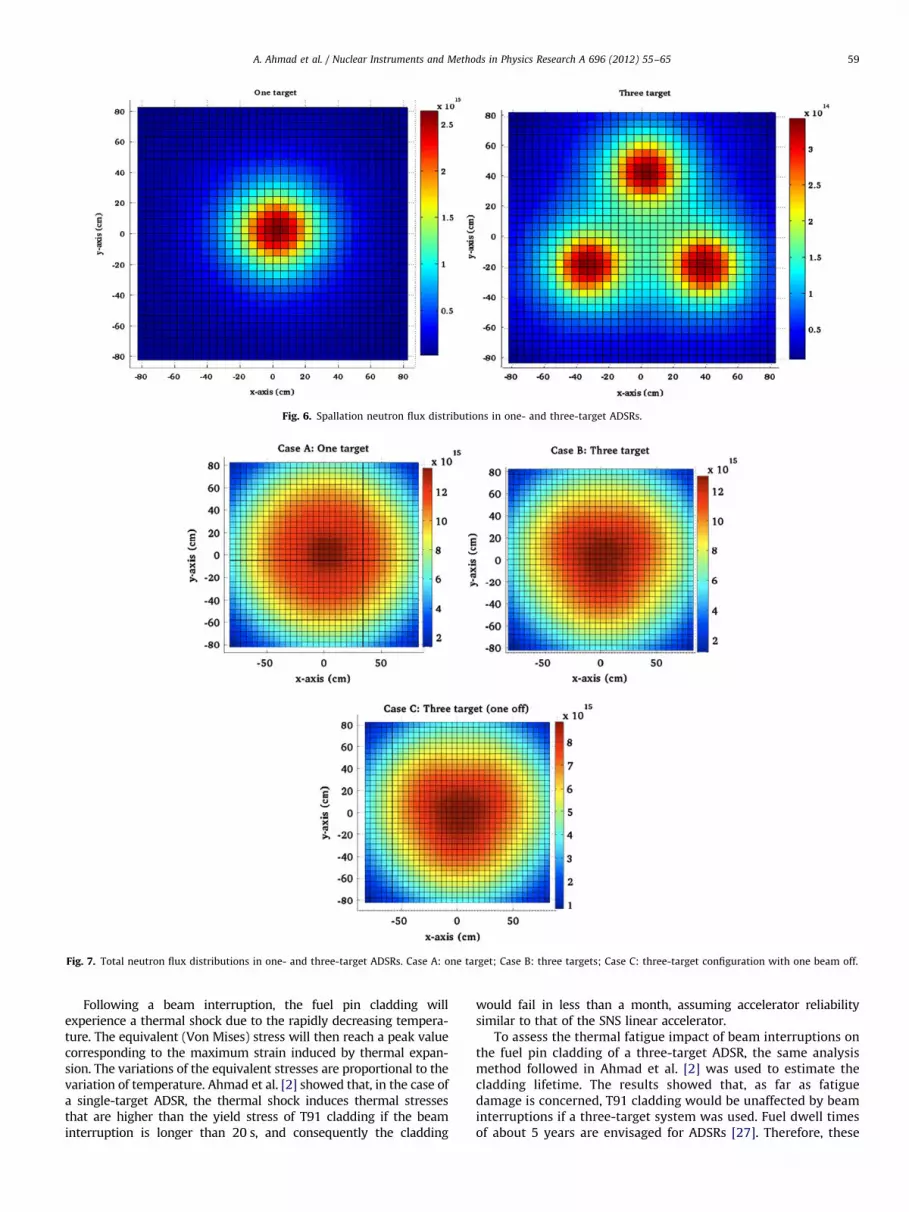
Fig. 6. Spallation neutron flux distributions in one- and three-target ADSRs.
Fig. 7. Total neutron flux distributions in one- and three-target ADSRs. Case A: one target; Case B: three targets; Case C: three-target configuration with one beam off.
A. Ahmad et al. / Nuclear Instruments and Methods in Physics Research A 696 (2012) 55–65 59
Following a beam interruption, the fuel pin cladding willexperience a thermal shock due to the rapidly decreasing tempera-ture. The equivalent (Von Mises) stress will then reach a peak valuecorresponding to the maximum strain induced by thermal expan-sion. The variations of the equivalent stresses are proportional to thevariation of temperature. Ahmad et al. [2] showed that, in the case ofa single-target ADSR, the thermal shock induces thermal stressesthat are higher than the yield stress of T91 cladding if the beaminterruption is longer than 20 s, and consequently the cladding
would fail in less than a month, assuming accelerator reliabilitysimilar to that of the SNS linear accelerator.
To assess the thermal fatigue impact of beam interruptions onthe fuel pin cladding of a three-target ADSR, the same analysismethod followed in Ahmad et al. [2] was used to estimate thecladding lifetime. The results showed that, as far as fatiguedamage is concerned, T91 cladding would be unaffected by beaminterruptions if a three-target system was used. Fuel dwell timesof about 5 years are envisaged for ADSRs [27]. Therefore, these

Table 4Multi-target ADSR comparisons.
Case Total beam
current
(mA)
keff Total core
power (MWth)
A. One target 1.000 0.97171 73.5�10�4 80
B. Three targets 0.431 0.98781 73.4�10�4 80
C. Three targets (one off) 0.438 0.98762 73.6�10�4 80
Fig. 8. Fuel cladding inner surface temperature variation during a 30 s beam
interruption in one- and three-target ADSRs at 12.8 kW fuel pin power.
Fig. 9. ADSR dynamic response to a �0:01508ðDk=kÞ control rod insertion.
A. Ahmad et al. / Nuclear Instruments and Methods in Physics Research A 696 (2012) 55–6560
calculations show that ADSR fuel cladding mechanical integritywould not be limited by thermal fatigue damage if multipletargets are used, even if accelerator reliability is no better thanthat of contemporary high-power proton accelerators.
The fuel cladding is the focus of attention as it forms the barrierthat prevents fission fragments from leaking into the coolant circuit.As long as the cladding maintains its integrity, thermo-mechanicaldamage to the fuel pellets is of limited significance.
3. ADSR shutdown
Inherent safety is one of the attractive features of ADSRs. Based onan intrinsic margin of subcriticality, an ADSR shutdown is believed tobe quick and simple. Switching the accelerator beam off terminatesthe production of spallation neutrons in the target. Consequently, thefission chain reaction will no longer be sustained and the core powerwill fall to the decay heat level. In this context, it is interesting toperform a dynamic response comparison of an ADSR shutdown usingbeam halt and control rod insertion. Both cases were modelledusing the PTS-ADS code. The beam halt shutdown mechanism wassimulated by simply removing the source term from the pointkinetics model at a time t. An ADSR shutdown using control rodswas simulated by inserting a negative reactivity equivalent to acontrol rod insertion in real shutdown cases over a suitable timeinterval (less than 0.5 s). The neutron source remained in operationduring the addition of this negative reactivity.
3.1. Control rod insertion
Fig. 9 shows the dynamic power response of an ADSR follow-ing a reactivity insertion of �0:01508ðDk=kÞ at different values ofkeff. This value of negative reactivity insertion was used byMahalakshmi [21] as the total reactivity worth of a control rod
in a typical fast reactor. As long as the proton beam and thereforethe neutron source is operating, control rod insertion reduces thepower level of an ADSR rather than shutting it down. Thus,control rods could be used for ADSR power level control, althoughthis can also be achieved by adjusting the total beam current.The effectiveness of control rods is inversely proportional to themargin of subcriticality. Adding �0:01508ðDk=kÞ to an ADSRoperating at keff ¼ 0:999 reduces the power to about 10% of theinitial steady-state level, whereas adding the same amount ofreactivity to an ADSR operating at keff ¼ 0:95 only reduces thepower by about 20%.
The variation of the steady-state power level as a function ofkeff following a control rod insertion observed in Fig. 9 can besupported by an intuitive mathematical model.
The power P of an ADSR can be expressed as [17]
P¼ Ckeff I
ð1�keff Þð1Þ
where C is a constant and I is the beam current.Defining �okeff to be the change in keff due to rod insertion
and �l to be the power-to-reactivity feedback coefficient, makingthe simplifying assumption that this is linear, the change inpower level DP will be given by
PþDP¼ Cðkeff�okeff�lDPÞI
ð1�keff þokeff þlDPÞ: ð2Þ
Here we would expect DP to be negative, of course.Dividing Eq. (2) by Eq. (1):
1þDP
P¼ð1�keff Þðkeff�okeff�lDPÞ
keff ð1�keff þokeff þlDPÞ: ð3Þ
Eq. (3) can be rearranged to give the following quadraticequation in DP=P:
kefflPDP
P
� �2
þ½keff ð1�keff þokeff ÞþlP�DP
Pþokeff ¼ 0: ð4Þ
Fig. 10 illustrates how the normalised steady-state power(1þDP=P) varies with keff according to Eq. (4) for the case wherelP¼ 0:0015 and o¼ 0:01508. It can be seen that the trend shownis in good qualitative agreement with that observed for thesimulations shown in Fig. 9.
3.2. Beam shutdown
The dynamic power response of an ADSR following a beamshutdown at different values of keff is shown in Fig. 11. High

Fig. 10. Normalised steady-state ADSR power as a function of keff for sample
control rod insertions (o¼ 0:01508) and increases in beam power (g¼ 2)
predicted by Eqs. (4) and (7).
Fig. 11. ADSR dynamic response to beam shutdown.
Fig. 12. The beam current required to run an ADSR at different power levels for
different values of keff.
A. Ahmad et al. / Nuclear Instruments and Methods in Physics Research A 696 (2012) 55–65 61
margins of subcriticality ensure quick and effective ADSR shut-down: the power falls quickly to a level that depends on the keff ofthe core before decreasing at a slower rate that is determined bythe decay constants of the delayed neutron groups. Note that theeffects of decay heat are neglected in this analysis.
The response changes dramatically for very narrow margins ofsubcriticality as the effects of the fuel and coolant temperaturefeedback mechanisms become more significant. As shown Fig. 11,in the case of keff ¼ 0:999, beam shutdown does not lead to ADSRshutdown. Instead, the power level will only be lowered by about23%. The effect of the temperature-to-reactivity feedback mechan-isms can be appreciated by comparing the response of the ‘‘solidline’’ with the ‘‘No feedback’’ line.
Operating an ADSR with a very narrow margin of subcriticalityminimises the beam current and power requirements for a givenreactor power level. Moreover, it increases fuel burn-up as morefission reactions will be induced per source neutron. Fig. 12 showsthe variation in the current of a 1 GeV proton beam needed to runan ADSR at different values of keff for different core power levels.As illustrated by the keff ¼ 0:999 case in Fig. 11, the desire tominimise the margin of subcriticality in order to reduce ADSR
beam power requirements must be traded off against the need tomaintain a margin of subcriticality for reasons of controllabilityand safety. A value of keff ¼ 0:985 appears to be a good compro-mise between these competing requirements.
4. Beam overpower
The response of the system to a sudden increase in beamcurrent is a scenario that needs to be studied to ensure successfulaccelerator–reactor integration in ADSRs. Although any beamoverpower accidents caused by equipment malfunctions arelikely to be of very short duration (the order of milliseconds), itis important to study more prolonged overpower scenarios whichmay result from human error. Any sudden increase in the coretemperature will need to be analysed, especially the effect on thefuel pin cladding, given the importance of the cladding inpreventing the release of gaseous fission products.
An extreme beam overpower accident was modelled using thePTS-ADS code by increasing the strength of the source term in thepoint kinetics model at a given time. Fig. 13 shows the dynamicresponse in the normalised reactor power upon doubling the beamcurrent for different values of keff. For a relatively large margins ofsubcriticality, the increase in power is almost proportional to thatof the beam current. In the keff ¼ 0:95 case, the power increases byabout 94% following a doubling of beam current.
From Eq. (1), it is clear that P is much more sensitive to keff
when the system is very close to criticality. When the beamcurrent is doubled the temperatures of the fuel and coolantincrease accordingly, and this adds negative reactivity to thesystem which reduces keff and consequently limits the extent ofthe increase in reactor power. Due to the impact of thistemperature-to-reactivity feedback, the percentage increase inpower following a doubling of beam current reduces as the valueof keff approaches unity, as shown in Fig. 13.
As before, the variation of the steady-state power level as afunction of keff following a change in beam current observed inFig. 13 can be supported by an intuitive mathematical model.
Define g to be the factor by which the beam current ismultiplied, and �l again to be the power-to-reactivity feedbackcoefficient (assumed linear). Multiplying the beam current by afactor g, the change in power level DP will be given by
PþDP¼ Cðkeff�lDPÞgI
ð1�keff þlDPÞ: ð5Þ

Fig. 14. Dynamic thermal response in T91 cladding upon doubling the beam
current at keff ¼ 0:973.
Fig. 15. T91 creep
Fig. 13. Normalised dynamic power response upon doubling the beam current at
different keff values.
A. Ahmad et al. / Nuclear Instruments and Methods in Physics Research A 696 (2012) 55–6562
Dividing Eq. (5) by Eq. (1):
1þDP
P¼gð1�keff Þðkeff�lDPÞ
keff ð1�keff þlDPÞ: ð6Þ
Eq. (6) can be rearranged to give the following quadraticequation in DP=P:
kefflPDP
P
� �2
þ½keff ð1�keff ÞþlP½keff þgð1�keff Þ�DP
P
�ðg�1Þkeff ð1�keff Þ ¼ 0: ð7Þ
Fig. 10 illustrates how the normalised steady-state power(1þDP=P) varies with keff according to Eq. (7) for the case wherelP¼ 0:0015 and g¼ 2. It can be seen that the trend displayed is ingood qualitative agreement with that observed for the simula-tions shown in Fig. 13. When operating an ADSR with keff nearcriticality g has to increase significantly to provide the sameincrease in the thermal power as can be achieved with a smallervalue of g at a lower value of keff.
The dynamic thermal response to a beam overpower accidentwith T91 cladding is shown in Fig. 14. The steady-state claddingtemperature was assumed to be 550 1C, which corresponds to themaximum allowed fuel pin power of 12.8 kW for T91 fuelcladding [2]. Fig. 14 shows that doubling the beam current atkeff ¼ 0:973 increases the fuel centreline temperature by about735 K and a new steady-state temperature of 2225 K will bereached after about 20 s. Although this is a significant tempera-ture increase, the fuel temperature is still below the meltingtemperature of PuO2 (which is lower than that of UO2 or anyintermediate MOX composition) in the MOX fuel matrix which isaround 2761 K [26]. In the case shown in Fig. 14, the cladding andcoolant temperature increases of 186 K and 147 K respectively areof more concern. Prolonged core operation at elevated tempera-tures accelerates cladding failure due to high temperature creep.The variation of the time-to-rupture as a function of the claddingtemperature is shown in Fig. 15. During a beam overpoweraccident in which, due to operator error, the beam current isdoubled, the cladding temperature reaches a higher steady-statetemperature of about 1000 K, which according to Fig. 15 willinduce cladding rupture after only 3 min.
rupture curve.

A. Ahmad et al. / Nuclear Instruments and Methods in Physics Research A 696 (2012) 55–65 63
5. Pulsed beam operation
Among the accelerator technologies under consideration fordeployment in an ADSR, the Fixed Field Alternating Gradient(FFAG) concept is seen as a promising candidate [31]. The FFAGoffers better performance than a cyclotron in terms of its beamcharacteristics such as beam focusing and rapid acceleration [22].Moreover, due to their compact structure, FFAGs should havemuch lower construction costs than linear accelerators. The FFAGwas developed for rapid acceleration, which is ideal for systemsrequiring both high beam power and high repetition rates [30]. Itshould be noted, however, that current FFAG technology is stillseveral orders of magnitude from the powers required forindustrial ADSR systems. An FFAG accelerator has been coupledto a reactor core in Kyoto University Research Reactor Institute(KURRI) and studies of its performance conducted [33,32]. AnFFAG delivers accelerated protons in the form of discontinuousbunches, which in an ADSR would result in a pulsed spallationsource. This, in turn, would lead to oscillations in the number offission reactions within the subcritical core and therefore in thecore power.
A full analysis of the impact of pulsed operation on themechanical integrity of the fuel pin cladding is presented inAhmad and Parks [1]. In this study, pulsed beam operation isrevisited to illustrate the possible use of pulsed operation tomeasure the reactivity of the core of an ADSR accurately. Previousstudies have shown that core reactivity can be measured usingapproaches such as the source-jerk method, area method andcurrent-to-flux indicator [10,4]. These methods require a changein the neutron flux to be able to measure the reactivity. It hasbeen suggested that this could be achieved by relying on accel-erator beam interruptions [4]. Pulsed-beam operation, on theother hand, has the potential to provide continuous, online corereactivity measurements without the need for frequent, poten-tially problematic, beam interruptions.
The proposed reactivity monitoring using pulsed beam opera-tion method is based on the source-jerk method. It relies on sourceperturbations, such as a beam cut-off, to estimate the reactivity ofthe system. In an ADSR, the source-jerk method can be implemen-ted by recording the values of the neutron flux before and after thesource cut-off. The evolution of the neutron flux in a subcriticalsystem upon beam interruptions can be expressed as [10]
nðtÞ ¼ n0eaðt�t0Þ þbeff
r�beff
n0½eaðt�t0Þ�1� ð8Þ
where a is the prompt neutron decay constant, beff is the effectivedelayed neutron fraction, r is the reactivity and t0 is the time atwhich is external source is cut off.
Following the rapid decay of prompt neutrons from level n0,the neutron flux reaches an asymptotic level n1. Using Eq. (8), thereactivity can be found from
r¼ beff
n1�n0
n1
� �ð9Þ
and hence the effective multiplication factor of the system can bewritten as
keff ¼n1
n1�beff ðn1�n0Þ: ð10Þ
The dynamic neutronic response to pulsed operation in anADSR is shown in Fig. 16. Here the results from the PTS-ADS codeand its point kinetics model are compared with those given byEVENT [8]. EVENT is a deterministic code produced by ImperialCollege London, which solves the time-dependent radiationtransport equation. The ADSR model consisted of a toroidal coreregion surrounded by LBE coolant. 11 group cross-sections for the
two regions were generated using a steady-state calculation inMONK, the commercial UK Monte Carlo code [3]. Use of a coarsergroup structure was found to result in an error of 3% in keff, whilethe error was reduced to around 1% for 11 groups. A volumesource was defined over the spallation target region. EVENT wasthen used to solve the time-dependent transport equation.
The properties of the pulsed beam operation illustrated inFig. 16 are listed in Tables 5 and 6. The choices of the beamfrequency and beam-off time were based on the current capabil-ities of FFAG accelerators [1]. As for the pulse width, a FFAGaccelerator delivers the proton pulse in 102100 ms. This timescaleis too short to be simulated in PTS-ADS and consequently a pulsewidth of 1 ms was chosen. The neutronic data in Tables 5 and 6refer to fast ADSR systems of the fuel composition shown inTable 2 and cooled by LBE.
The three cases shown in Fig. 16 represent operating a pulsed-beam ADSR at three different values of keff: 0.958, 0.978 and 0.996respectively. In general, a very good agreement between PTS-ADSand EVENT is observed. The predictions of keff by the two codesare shown in Table 7. These predictions were obtained using thesource-jerk method described in Eqs. (8) and (10). One canobserve that the PTS-ADS keff predictions generally deviate lessfrom the pre-defined values of keff than those of EVENT. This is notsurprising given that the source-jerk method is developed fromthe point kinetics model. In EVENT, the deviations seem to bedependent on the initial convergence of the steady-state beforethe pulsed mode starts. The advantages of this method as a way ofmonitoring ADSR reactivity are that it is simple, accurate and canbe used while the reactor is operating. The repetitions naturallyassociated with pulsed beam operation also offer a statisticaladvantage which will allow reactivity changes to be monitored asnuclear fuel burns up or is bred.
6. Conclusions
This paper is sought to provide a better understanding ofthe effects of accelerator-induced transients in ADSRs. A successfulintegration between accelerator and reactor technologies is of highimportance from an economic perspective and must be achieved forthe ADSR concept to advance. The different aspects of this integra-tion studied in this paper can be summarised as follows.
�
Current high-power proton accelerators are complex systemswith reliability that does not satisfy the nearly ‘‘trip-free’’operation required by ADSRs. Beam interruptions of differentdurations present real engineering and economic challengesthat need to be addressed. � The concept of a multiple-target ADSR seems to be effective inmitigating the effects of a beam loss. As long as only one of themultiple beams is lost at any given time, the multiple-targetsystem allows continued operation at a lower power levelduring beam interruptions. This mitigates the considerableeconomic risks associated with generation intermittency insingle-target systems. Moreover, only losing a fraction of thereactor power during a beam interruption reduces the magni-tude of the consequent temperature drop which will mitigatethermal fatigue issues in the fuel cladding. Additionally, themultiple-target concept improves the neutron economy in anADSR leading to a lower beam current demand.
� The presence of control rods is crucial in ADSRs. They providefurther control and safety to the system. An ADSR cannot becompletely shutdown using control rods only; the beam(s)must be shut off to achieve this. Control rods can be utilisedfor ADSR power control, a requirement in any nuclear powerplant. It has been observed that the effectiveness of control

Fig. 16. Comparison of the dynamic neutronic response to pulsed operation in an ADSR using EVENT and PTS-ADS.
Table 5Characteristics of pulsed beam operation.
Property Units Value Reference
Beam frequency Hz 100
Pulse width ms 1
Beam-off time ms 10
Delayed neutron fraction (beff ) 0.0035 [6]
Neutron lifetime (L) s�1 4.2�10�7 [6]
Table 6Delayed neutron data [6].
Group (i) Fraction (bi) Decay constant (li) (s�1)
1 8.6�10�5 0.0129
2 7.3�10�4 0.0313
3 6.55�10�4 0.1346
4 1.267�10�3 0.3443
5 5.8�10�4 1.3764
6 1.82�10�4 3.7425
A. Ahmad et al. / Nuclear Instruments and Methods in Physics Research A 696 (2012) 55–6564

Table 7PTS-ADS & EVENT predictions of keff using the source-jerk method.
Pre-defined keff EVENT EVENT
deviation (%)
PTS-ADS PTS-ADS
deviation (%)
0.9587 0.9566 �0.22 0.9586 �0.01
0.9783 0.9804 0.24 0.9783 0.00
0.9966 0.9964 �0.02 0.9959 �0.07
A. Ahmad et al. / Nuclear Instruments and Methods in Physics Research A 696 (2012) 55–65 65
rods in an ADSR is inversely proportional to the margin ofsubcriticality of the system. Shutting down an ADSR operatingvery near criticality is not straightforward due to potentialreactivity swings and the availability of control rods providesfurther safety assurance in this scenario. A keff value of 0.985appears to be a good compromise between the competingdemands of core controllability and safety and the minimisa-tion of beam requirements.
� Although significant beam overpower accidents are veryunlikely to occur in practice, a hypothetical scenario showedthat such an accident can cause substantial damage in a veryshort time especially to the fuel pin cladding. Temperaturefeedback mechanisms play an important role in preventingsharp power excursions in an ADSR operating with a relativelynarrow margin of subcriticality.
� Pulsed beam operation, which is associated with the possibledeployment of pulsed accelerators such as the FFAG in ADSRs,can be used to perform online a simple and accurate measure-ment of core reactivity using the source-jerk method. Repeatedpulses offer a statistically strong data set through which tomonitor any reactivity loss or build-up.
References
[1] A. Ahmad, G. Parks, Annals of Nuclear Energy 42 (2012) 35.[2] A. Ahmad, S. Sheehy, G. Parks, Annals of Nuclear Energy 46 (2012) 97.[3] M. Armishaw, A. Cooper, Current status and future direction of the MONK
software package, in: Proceedings of the 8th International Conference onNuclear Criticality Safety, St. Petersburg, Russia, 2007.
[4] P. Baeten, H. Ait Abderrahim, Progress in Nuclear Energy 43 (2003) 413.[5] C.D. Bowman, Annual Review of Nuclear and Particle Science 48 (1) (1998)
505.[6] A. D’Angelo, B. Arien, V. Sobolev, G. Van den Eynde, F. Gabrielli, Benchmark on
Beam Interruptions in an Accelerator-Driven System Final Report on Phase ICalculations, Technical Report NEA/NSC/DOC(2003)17, NEA, 2003.
[7] A. D’Angelo, B. Arien, V. Sobolev, G. Van den Eynde, F. Gabrielli, Benchmark onBeam Interruptions in an Accelerator-Driven System Final Report on Phase IICalculations, Technical Report NEA/NSC/DOC(2004)7, NEA, 2004.
[8] C. de Oliveira, Progress in Nuclear Energy 18 (1986) 227.[9] D. Findlay, High power operational experience at ISIS, in: ICFA Advanced
Beam Dynamics Workshop on High-Intensity and High-Brightness HadronBeams, Morschach, Switzerland, 2010, pp. 381–385.
[10] F. Gabrielli, M. Carta, A. D’Angelo, W. Maschek, A. Rineiski, Progress inNuclear Energy 50 (2008) 370.
[11] J. Galambos, SNS operation experience: expectations and realities, in: ICFAAdvanced Beam Dynamics Workshop on High-Intensity and High-BrightnessHadron Beams, Morschach, Switzerland, 2010, pp. 11–15.
[12] J. Galambos, Private communications, May 2011.[13] J. Galambos, T. Koseki, M. Seidel, Commissioning strategies, operations and
performance, beam loss management, activation, machine protection, in:ICFA Advanced Beam Dynamics Workshop on High-Intensity and High-Brightness Hadron Beams, Tennessee, USA, 2008, pp. 489–496.
[14] L. Goncalves, A. Ahmad, G. Parks, W. Nuttall, S. Steer, A comparison of ADSRconcepts for power generation, in: Proceedings of the OECD Nuclear EnergyAgency International Workshop on Technology and Components of Accel-erator Driven Systems, Karlsruhe, Germany, 2010.
[15] L. Hardy, A brief history of accelerator reliability /www.tlabs.ac.za/ARW2011_CD/Monday/session1/Hardy_history_of_reliability2.pptS, Presented at the AcceleratorReliability Workshop, 2011 (accessed 10-10-11).
[16] International Atomic Energy Agency, Thorium fuel cycle—Potential Benefitsand Challenges, Technical Report IAEA-TECDOC-1450, IAEA, 2005.
[17] S. Kapoor, Pramana—Journal of Physics 59 (2002) 941.[18] D. Kececioglu, Reliability Engineering Handbook, vol. 1, Prentice Hall, New Jersey,
1991.[19] Y. Liu, A Study on the Feasibility of Electron-Based Accelerator Driven
Systems for Nuclear Waste Transmutation, Ph.D. Thesis, North Carolina StateUniversity, 2006.
[20] Los Alamos National Laboratory, Welcome to the Home of the MCNPX Code/http://mcnpx.lanl.gov/S, 2011 (accessed on 27-03-12).
[21] B. Mahalakshmi, Annals of Nuclear Energy 18 (1) (1991) 25.[22] Y. Mori, FFAG accelerators and their applications, in: Proceedings of the EPAC
2006, Edinburgh, Scotland, 2006, pp. 950–954.[23] MYRRHA, The MYRRHA Fuel Element and Fuel Assembly Pre-design /http://
myrrha.sckcen.be/en/Engineering/Spallation_targetS, 2012 (accessed on27-03-12).
[24] H. Nifenecker, O. Meplan, S. David, Comptes Rendus de l’Academie desSciences—Series IV—Physics-Astrophysics 2 (1) (2001) 163.
[25] F. Pairot, PCSR Sub-Chapter 4.3 Nuclear Design, Technical Report UKEPR-0002-043 Issue 04, UK-EPR, 2011.
[26] S. Popov, J. Carbajo, V. Ivanov, G. Yoder, Thermophysical Properties of MOXand UO2 Fuels Including Effects of Irradiation, Technical Report ORNL/TM-2000/351, ORNL, 2000.
[27] C. Rubbia, J. Rubio, S. Buono, F. Carminati, N. Fietier, J. Galvez, C. Gel�es, Y.Kadi, R. Klapisch, P. Mandrillon, J. Revol, C. Roche, Conceptual Design of a FastNeutron Operated High Power Energy Amplifier, Technical Report CERN/AT/95-44 (ET), European Organization for Nuclear Research, 1995.
[28] S. Steer, M.-A. Cardin, W. Nuttall, G. Parks, L. Goncalves, Nuclear Engineeringand Design 243 (2012) 135.
[29] S. Steer, W. Nuttall, G. Parks, L. Goncalves, Electric Power Systems Research81 (2011) 1662.
[30] K. Symon, D. Kerst, L. Jones, L. Laslett, K. Terwilliger, Physical Review 103(1956) 1837.
[31] H. Takahashi, Progress in Nuclear Energy 37 (2000) 363.[32] M. Tanigaki, Y. Mori, M. Inoue, K. Mishima, S. Shiroya, Y. Ishi, S. Fukumoto, S.
Machida, Present status of FFAG accelerators in KURRI for ADS study, in:Proceedings of EPAC 2006, Edinburgh, Scotland, 2006, pp. 2367–2369.
[33] A. Yamamoto, S. Shiroya, Annals of Nuclear Energy 30 (2003) 1425.