Embed Size (px)
Citation preview
SSUD13-311
Structural
Engineering Assignment 2
Samuel Beckett Bridge
STUDENT (SID):
Hongsheng YE (13262123)
2014/11/11 Tuesday
2014
Nick YEhs
1 / 9
Samuel Beckett Bridge
Executive Summary
Samuel Beckett Bridge (Irish: Droichead Samuel Beckett) is a cable-stayed bridge in Dublin that joins Sir
John Rogerson's Quay on the south side of the River Liffey to Guild Street and North Wall Quay in the
Docklands area.
It is the Dublin City’s newest bridge, and is now established as a landmark structure spanning the
maritime gateway to the City. The bridge is located East of the City’s centre and within the ‘heart’ of
the newly developed docklands’ area, facilitating an important urban transport link for private car use,
public transport, cyclists and pedestrians; and contributing towards the improved environmental,
commercial and social development of the urban area in which it is located.
Geometry
Describe the principal structural system (load-bearing form) adopted for the
structure.
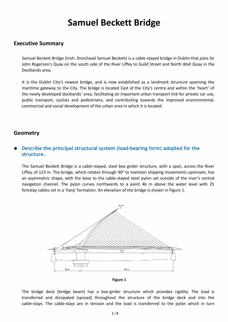
The Samuel Beckett Bridge is a cable-stayed, steel box girder structure, with a span, across the River
Liffey, of 123 m. The bridge, which rotates through 90° to maintain shipping movements upstream, has
an asymmetric shape, with the base to the cable-stayed steel pylon set outside of the river’s central
navigation channel. The pylon curves northwards to a point 46 m above the water level with 25
forestay cables set in a ‘harp’ formation. An elevation of the bridge is shown in Figure 1.
Figure 1
The bridge deck (bridge beam) has a box-girder structure which provides rigidity. The load is
transferred and dissipated (spread) throughout the structure of the bridge deck and into the
cable-stays. The cable-stays are in tension and the load is transferred to the pylon which in turn
2 / 9
transfers the load to the bridge’s foundation, and in turn to the ground. The pylon is in compression.
When a load is applied to a member of the bridge structure, that member will deform to some extent
and when this deformation takes place, internal forces in the material of the structural member will
resist it. These internal forces are called stresses. The force transmitted across a section of the
structural member divided by the area of that section gives the intensity of the stress; it therefore has
the same units as pressure – pascals (Pa) or N/m2.
Outline the architectural inspiration/rationale that influenced the shape of the structure.
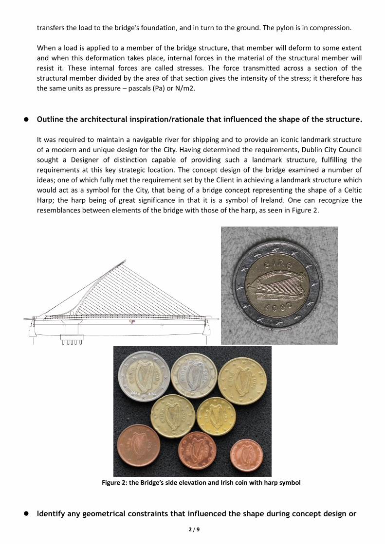
It was required to maintain a navigable river for shipping and to provide an iconic landmark structure
of a modern and unique design for the City. Having determined the requirements, Dublin City Council
sought a Designer of distinction capable of providing such a landmark structure, fulfilling the
requirements at this key strategic location. The concept design of the bridge examined a number of
ideas; one of which fully met the requirement set by the Client in achieving a landmark structure which
would act as a symbol for the City, that being of a bridge concept representing the shape of a Celtic
Harp; the harp being of great significance in that it is a symbol of Ireland. One can recognize the
resemblances between elements of the bridge with those of the harp, as seen in Figure 2.
Figure 2: the Bridge’s side elevation and Irish coin with harp symbol
Identify any geometrical constraints that influenced the shape during concept design or
3 / 9
detailed design.
It was a requirement to design the bridge in such a way that the navigable channel in the centre of the
river was maintained. This meant that an opening bridge was required. The option of rotating the
bridge in the horizontal plane was chosen by the Designer, which led to an architectural and structural
engineering challenge. Due to the navigable channel in the centre of the river, the axis of rotation was
positioned closer to the South river bank. The challenge for the structural engineers was to provide an
elegant solution in terms of balance and strength. In order to produce an architecturally ‘balanced’
impression the tip of the pylon was placed at the centre of the river, and using the lines of the front
and back cable stays, a triangle was created, which architecturally ‘balances’ the bridge.
Load
Identify all of the design live loads imparted on the structure.
The assessment of the requirements of the bridge dictated that the bridge was to provide for two lanes
of traffic in both directions, one of which would provide for public transport – in the initial years
facilitating a dedicated bus lane, and for possible future years a provision for a light rail system, and
was also required to provide for ample space for pedestrians and cyclists. Therefore, its biggest live
loads must be from people and public transport. And wind force should be another outstanding load.
Also, the river should be one of outstanding load.
Describe any structural issues that arose once all of the loads had been identified.
It was a requirement to design the bridge in such a way that the navigable channel in the centre of the
river was maintained. This meant that an opening bridge was required. The option of rotating the
bridge in the horizontal plane was chosen by the Designer, which led to an architectural and structural
engineering challenge. Due to the navigable channel in the centre of the river, the axis of rotation was
positioned closer to the South river bank. The challenge for the structural engineers was to provide an
elegant solution in terms of balance and strength. In order to produce an architecturally ‘balanced’
impression the tip of the pylon was placed at the centre of the river, and using the lines of the front
and back cable stays, a triangle was created, which architecturally ‘balances’ the bridge. The bridge
span between quay walls is 123m and the height of the pylon from the mean tide level is 46m.These
were principally to protect the environmental impact on the river and its quay wall infrastructure, and
on the urban area in which the bridge was to be constructed and operated.
Analysis
Annotate diagrams of the structural system showing load paths for permanent
(dead) and imposed (live) loads. Note: choose only one live load for discussion (e.g.
wind load, earthquake load, occupancy floor load).
4 / 9
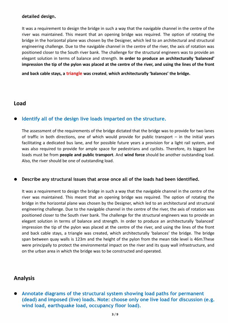
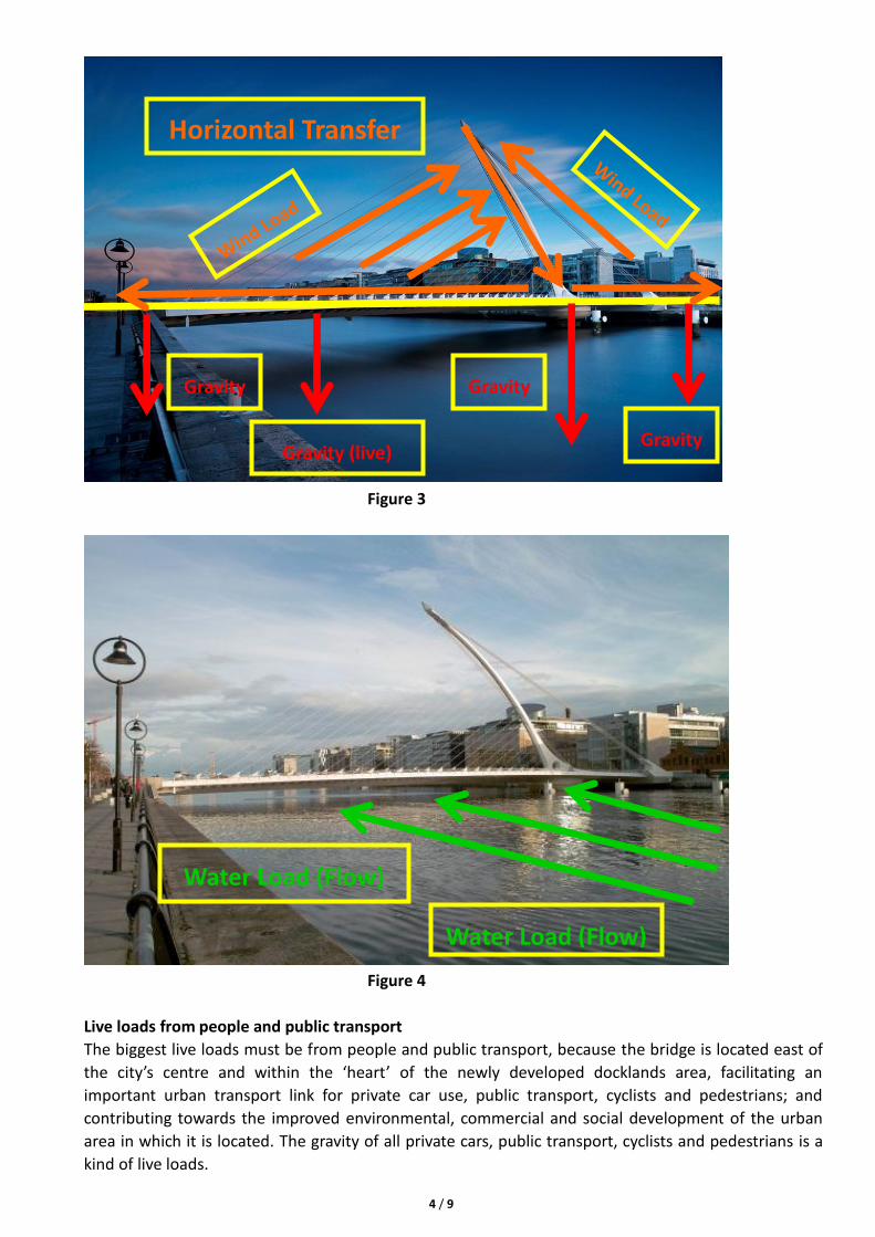
Figure 3
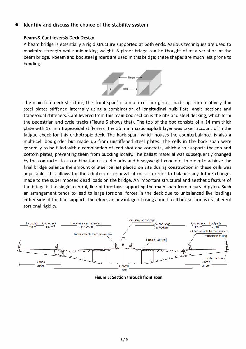
Figure 4
Live loads from people and public transport
The biggest live loads must be from people and public transport, because the bridge is located east of
the city’s centre and within the ‘heart’ of the newly developed docklands area, facilitating an
important urban transport link for private car use, public transport, cyclists and pedestrians; and
contributing towards the improved environmental, commercial and social development of the urban
area in which it is located. The gravity of all private cars, public transport, cyclists and pedestrians is a
kind of live loads.
Horizontal Transfer
Gravity
Water Load (Flow)
Water Load (Flow)
Gravity
Gravity (live) Gravity
5 / 9
Identify and discuss the choice of the stability system
Beams& Cantilevers& Deck Design
A beam bridge is essentially a rigid structure supported at both ends. Various techniques are used to
maximize strength while minimizing weight. A girder bridge can be thought of as a variation of the
beam bridge. I-beam and box steel girders are used in this bridge; these shapes are much less prone to
bending.
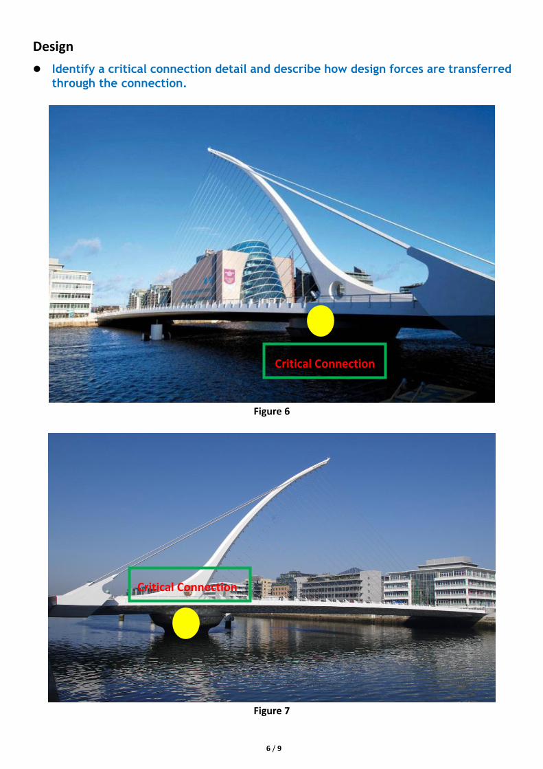
The main fore deck structure, the ‘front span’, is a multi-cell box girder, made up from relatively thin
steel plates stiffened internally using a combination of longitudinal bulb flats, angle sections and
trapezoidal stiffeners. Cantilevered from this main box section is the ribs and steel decking, which form
the pedestrian and cycle tracks (Figure 5 shows that). The top of the box consists of a 14 mm thick
plate with 12 mm trapezoidal stiffeners. The 36 mm mastic asphalt layer was taken account of in the
fatigue check for this orthotropic deck. The back span, which houses the counterbalance, is also a
multi-cell box girder but made up from unstiffened steel plates. The cells in the back span were
generally to be filled with a combination of lead shot and concrete, which also supports the top and
bottom plates, preventing them from buckling locally. The ballast material was subsequently changed
by the contractor to a combination of steel blocks and heavyweight concrete. In order to achieve the
final bridge balance the amount of steel ballast placed on site during construction in these cells was
adjustable. This allows for the addition or removal of mass in order to balance any future changes
made to the superimposed dead loads on the bridge. An important structural and aesthetic feature of
the bridge is the single, central, line of forestays supporting the main span from a curved pylon. Such
an arrangement tends to lead to large torsional forces in the deck due to unbalanced live loadings
either side of the line support. Therefore, an advantage of using a multi-cell box section is its inherent
torsional rigidity.
Figure 5: Section through front span
6 / 9
Design
Identify a critical connection detail and describe how design forces are transferred
through the connection.
Figure 6
Figure 7
Critical Connection
Critical Connection
7 / 9
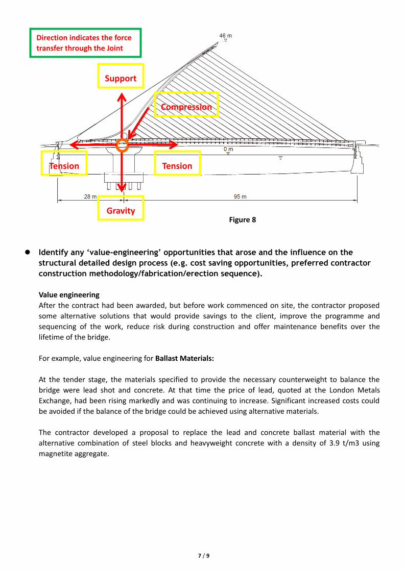
Figure 8
Identify any ‘value-engineering’ opportunities that arose and the influence on the
structural detailed design process (e.g. cost saving opportunities, preferred contractor
construction methodology/fabrication/erection sequence).
Value engineering
After the contract had been awarded, but before work commenced on site, the contractor proposed
some alternative solutions that would provide savings to the client, improve the programme and
sequencing of the work, reduce risk during construction and offer maintenance benefits over the
lifetime of the bridge.
For example, value engineering for Ballast Materials:
At the tender stage, the materials specified to provide the necessary counterweight to balance the
bridge were lead shot and concrete. At that time the price of lead, quoted at the London Metals
Exchange, had been rising markedly and was continuing to increase. Significant increased costs could
be avoided if the balance of the bridge could be achieved using alternative materials.
The contractor developed a proposal to replace the lead and concrete ballast material with the
alternative combination of steel blocks and heavyweight concrete with a density of 3.9 t/m3 using
magnetite aggregate.
Support
Direction indicates the force
transfer through the Joint
Compression
Tension Tension
Gravity
8 / 9
References
Cutter, J. & Flanagan, J. W. & Brown, P. & Rando, M. & Mo, G. (2011), ‘Samuel Beckett Bridge, Dublin,
Ireland’, Ice Proceedings.
Cutter, J. & Flanagan, J. W & Mo, G. (2010), ‘The Realisation of the Samuel Beckett Bridge – Dublin, Ireland’,
IABSE.