Embed Size (px)
Citation preview
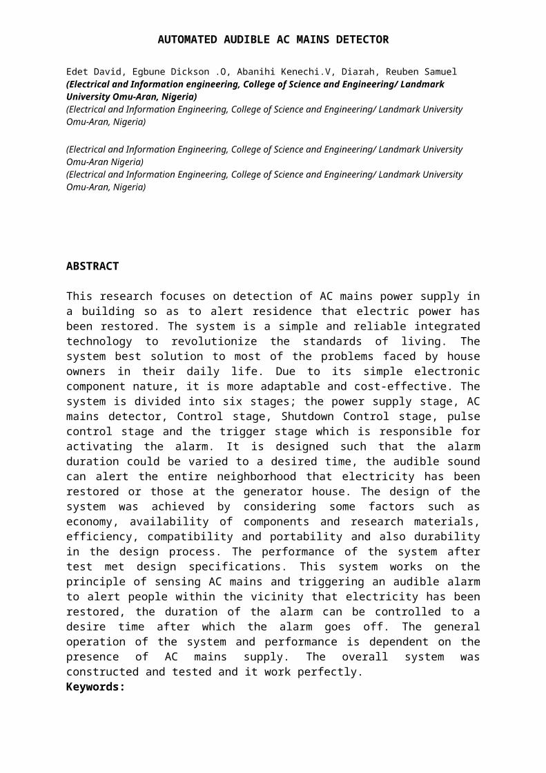
AUTOMATED AUDIBLE AC MAINS DETECTOR
Edet David, Egbune Dickson .O, Abanihi Kenechi.V, Diarah, Reuben Samuel(Electrical and Information engineering, College of Science and Engineering/ Landmark University Omu-Aran, Nigeria)(Electrical and Information Engineering, College of Science and Engineering/ Landmark University Omu-Aran, Nigeria)
(Electrical and Information Engineering, College of Science and Engineering/ Landmark University Omu-Aran Nigeria)(Electrical and Information Engineering, College of Science and Engineering/ Landmark University Omu-Aran, Nigeria)
ABSTRACT
This research focuses on detection of AC mains power supply ina building so as to alert residence that electric power hasbeen restored. The system is a simple and reliable integratedtechnology to revolutionize the standards of living. Thesystem best solution to most of the problems faced by houseowners in their daily life. Due to its simple electroniccomponent nature, it is more adaptable and cost-effective. Thesystem is divided into six stages; the power supply stage, ACmains detector, Control stage, Shutdown Control stage, pulsecontrol stage and the trigger stage which is responsible foractivating the alarm. It is designed such that the alarmduration could be varied to a desired time, the audible soundcan alert the entire neighborhood that electricity has beenrestored or those at the generator house. The design of thesystem was achieved by considering some factors such aseconomy, availability of components and research materials,efficiency, compatibility and portability and also durabilityin the design process. The performance of the system aftertest met design specifications. This system works on theprinciple of sensing AC mains and triggering an audible alarmto alert people within the vicinity that electricity has beenrestored, the duration of the alarm can be controlled to adesire time after which the alarm goes off. The generaloperation of the system and performance is dependent on thepresence of AC mains supply. The overall system wasconstructed and tested and it work perfectly.Keywords:
AUTOMATED AUDIBLE AC MAINS DETECTOR
Electronic circuit, AC mains detector, Audible alarm, Alarmcontrol, Shutdown control
1. INTRODUCTION
The present device is in the technical field of electronics.More particularly, the present device is in the technicalfield of an automated audible AC mains detectorConventional AC means devices, are complex and are notcompact, also do not possess the ability to vary or controlledthe duration of the alarm to a desire time after which thealarm goes off. Further, it is not an uncommon experience torealize that the device alarm does not automatically switchits self-off unless someone goes to put it off. Further, thedevices processes only a particular kind of frequency. The aim of this project is to alert residence using generatingplant, that electric power has been restored.
2. DESIGN
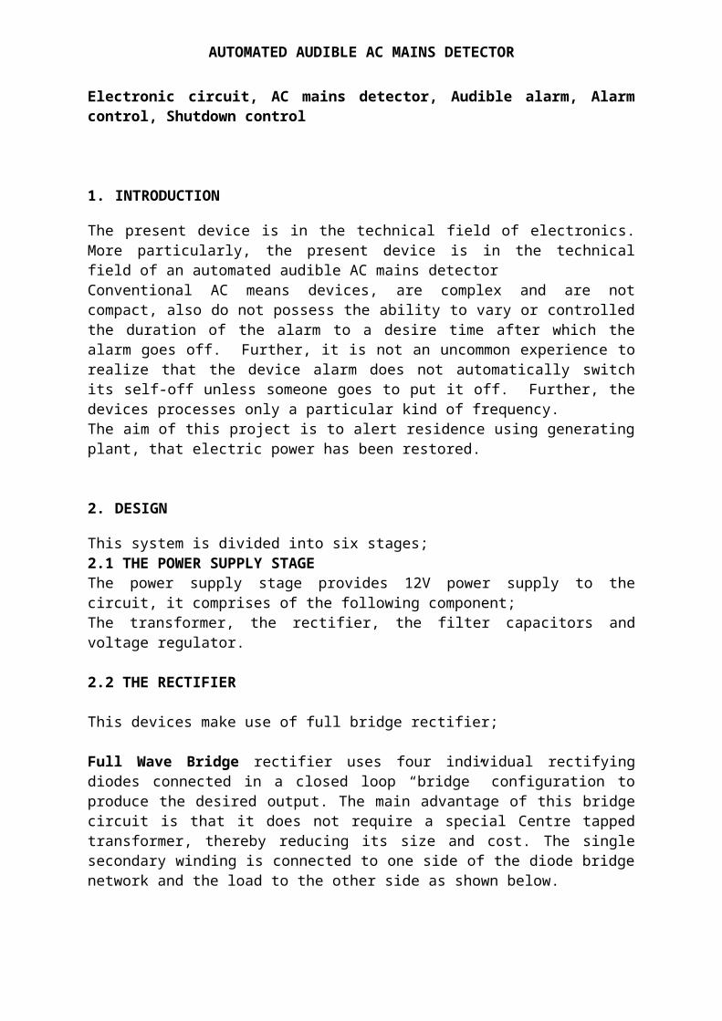
This system is divided into six stages;2.1 THE POWER SUPPLY STAGEThe power supply stage provides 12V power supply to thecircuit, it comprises of the following component;The transformer, the rectifier, the filter capacitors andvoltage regulator.
2.2 THE RECTIFIER
This devices make use of full bridge rectifier;
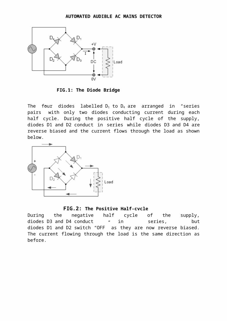
Full Wave Bridge rectifier uses four individual rectifyingdiodes connected in a closed loop “bridge” configuration toproduce the desired output. The main advantage of this bridgecircuit is that it does not require a special Centre tappedtransformer, thereby reducing its size and cost. The singlesecondary winding is connected to one side of the diode bridgenetwork and the load to the other side as shown below.
AUTOMATED AUDIBLE AC MAINS DETECTOR
The four diodes labelled D1 to D4 are arranged in “seriespairs” with only two diodes conducting current during eachhalf cycle. During the positive half cycle of the supply,diodes D1 and D2 conduct in series while diodes D3 and D4 arereverse biased and the current flows through the load as shownbelow.
During the negative half cycle of the supply,diodes D3 and D4 conduct in series, butdiodes D1 and D2 switch “OFF” as they are now reverse biased.The current flowing through the load is the same direction asbefore.
FIG.1: The Diode Bridge
FIG.2: The Positive Half-cycle
AUTOMATED AUDIBLE AC MAINS DETECTOR
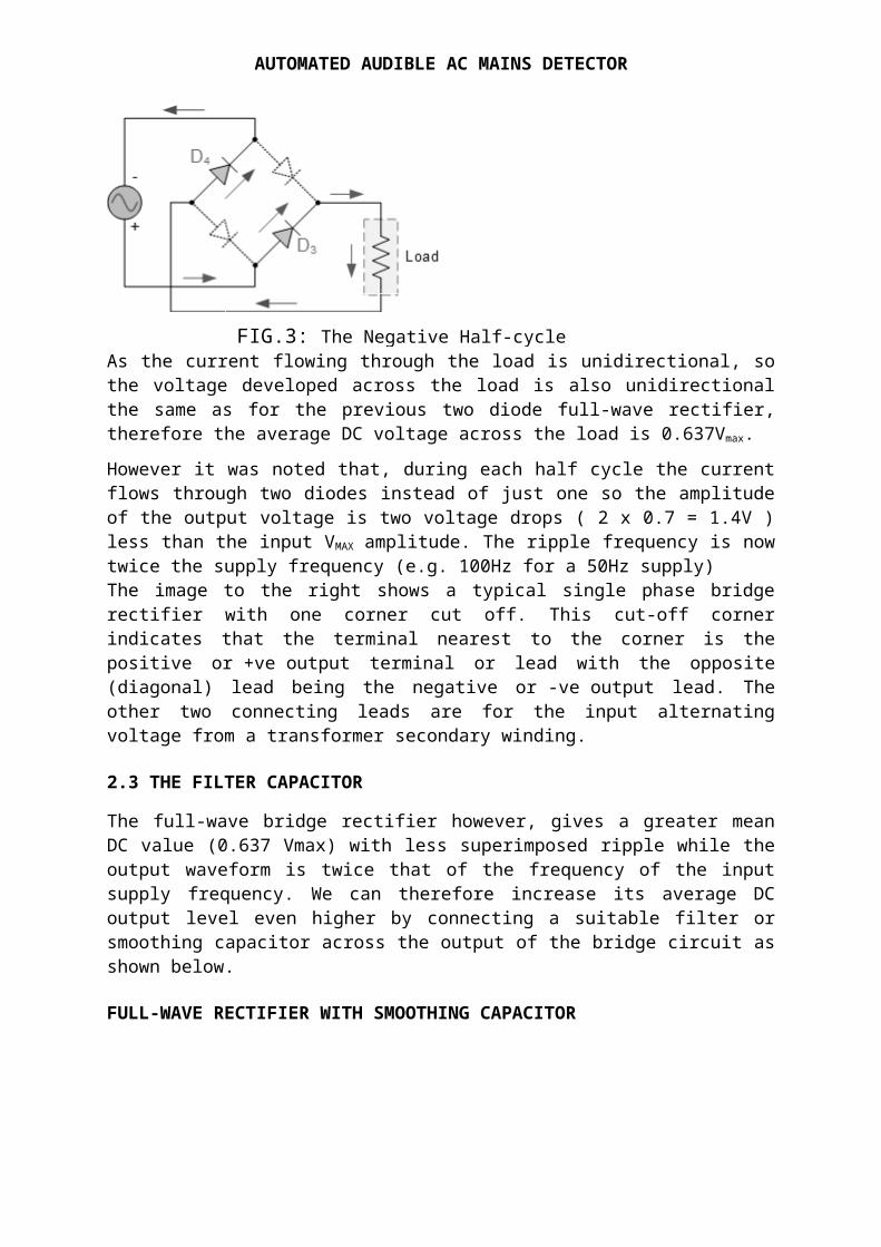
As the current flowing through the load is unidirectional, sothe voltage developed across the load is also unidirectionalthe same as for the previous two diode full-wave rectifier,therefore the average DC voltage across the load is 0.637Vmax.However it was noted that, during each half cycle the currentflows through two diodes instead of just one so the amplitudeof the output voltage is two voltage drops ( 2 x 0.7 = 1.4V )less than the input VMAX amplitude. The ripple frequency is nowtwice the supply frequency (e.g. 100Hz for a 50Hz supply)The image to the right shows a typical single phase bridgerectifier with one corner cut off. This cut-off cornerindicates that the terminal nearest to the corner is thepositive or +ve output terminal or lead with the opposite(diagonal) lead being the negative or -ve output lead. Theother two connecting leads are for the input alternatingvoltage from a transformer secondary winding.
2.3 THE FILTER CAPACITOR
The full-wave bridge rectifier however, gives a greater meanDC value (0.637 Vmax) with less superimposed ripple while theoutput waveform is twice that of the frequency of the inputsupply frequency. We can therefore increase its average DCoutput level even higher by connecting a suitable filter orsmoothing capacitor across the output of the bridge circuit asshown below.
FULL-WAVE RECTIFIER WITH SMOOTHING CAPACITOR
FIG.3: The Negative Half-cycle
AUTOMATED AUDIBLE AC MAINS DETECTOR
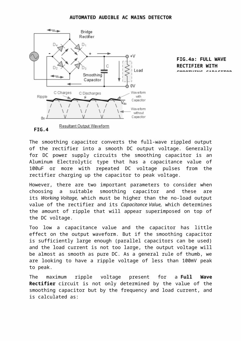
The smoothing capacitor converts the full-wave rippled outputof the rectifier into a smooth DC output voltage. Generallyfor DC power supply circuits the smoothing capacitor is anAluminum Electrolytic type that has a capacitance value of100uF or more with repeated DC voltage pulses from therectifier charging up the capacitor to peak voltage.However, there are two important parameters to consider whenchoosing a suitable smoothing capacitor and these areits Working Voltage, which must be higher than the no-load outputvalue of the rectifier and its Capacitance Value, which determinesthe amount of ripple that will appear superimposed on top ofthe DC voltage.Too low a capacitance value and the capacitor has littleeffect on the output waveform. But if the smoothing capacitoris sufficiently large enough (parallel capacitors can be used)and the load current is not too large, the output voltage willbe almost as smooth as pure DC. As a general rule of thumb, weare looking to have a ripple voltage of less than 100mV peakto peak.The maximum ripple voltage present for a Full WaveRectifier circuit is not only determined by the value of thesmoothing capacitor but by the frequency and load current, andis calculated as:
FIG.4
FIG.4a: FULL WAVE RECTIFIER WITH SMOOTHING CAPACITOR
AUTOMATED AUDIBLE AC MAINS DETECTOR
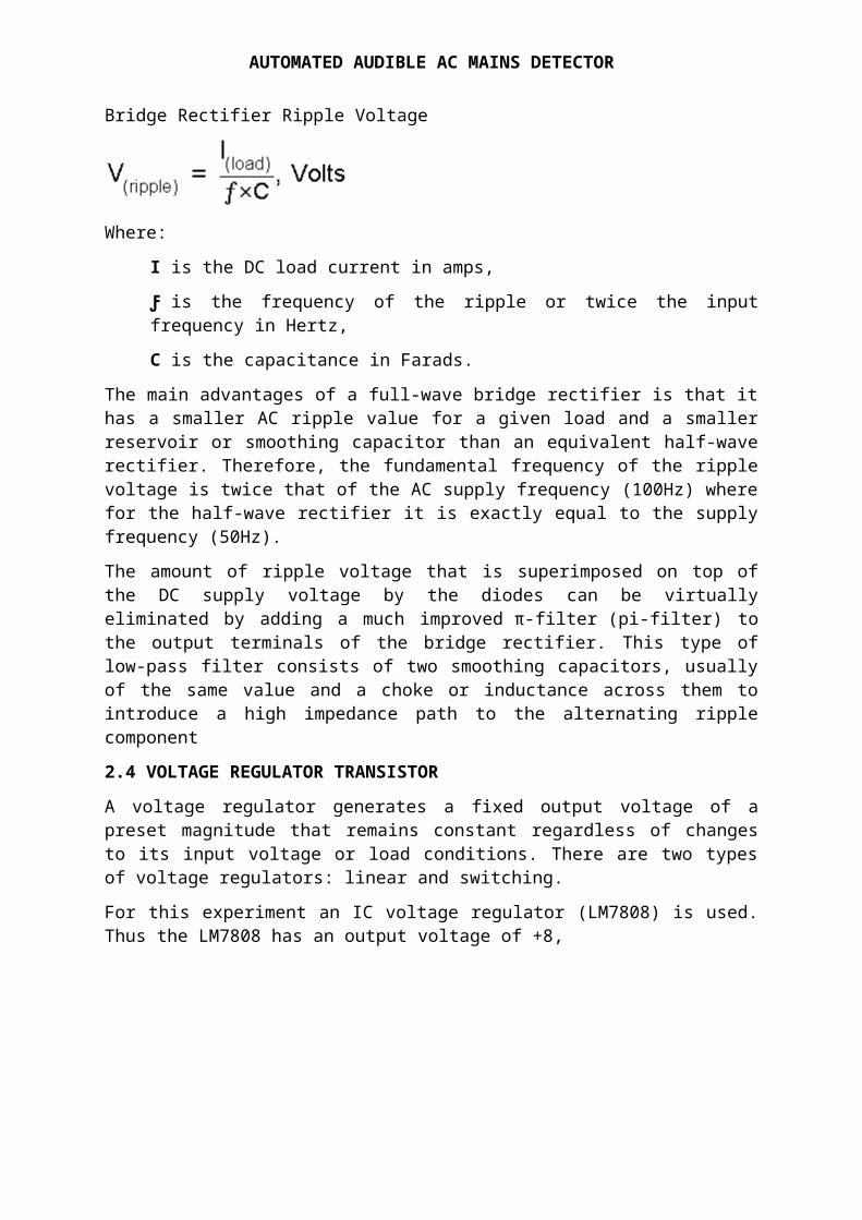
Bridge Rectifier Ripple Voltage
Where: I is the DC load current in amps,Ƒ is the frequency of the ripple or twice the inputfrequency in Hertz,C is the capacitance in Farads.
The main advantages of a full-wave bridge rectifier is that ithas a smaller AC ripple value for a given load and a smallerreservoir or smoothing capacitor than an equivalent half-waverectifier. Therefore, the fundamental frequency of the ripplevoltage is twice that of the AC supply frequency (100Hz) wherefor the half-wave rectifier it is exactly equal to the supplyfrequency (50Hz).The amount of ripple voltage that is superimposed on top ofthe DC supply voltage by the diodes can be virtuallyeliminated by adding a much improved π-filter (pi-filter) tothe output terminals of the bridge rectifier. This type oflow-pass filter consists of two smoothing capacitors, usuallyof the same value and a choke or inductance across them tointroduce a high impedance path to the alternating ripplecomponent2.4 VOLTAGE REGULATOR TRANSISTORA voltage regulator generates a fixed output voltage of apreset magnitude that remains constant regardless of changesto its input voltage or load conditions. There are two typesof voltage regulators: linear and switching.For this experiment an IC voltage regulator (LM7808) is used.Thus the LM7808 has an output voltage of +8,
AUTOMATED AUDIBLE AC MAINS DETECTOR
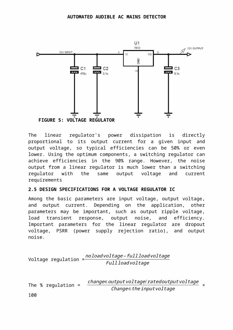
The linear regulator's power dissipation is directlyproportional to its output current for a given input andoutput voltage, so typical efficiencies can be 50% or evenlower. Using the optimum components, a switching regulator canachieve efficiencies in the 90% range. However, the noiseoutput from a linear regulator is much lower than a switchingregulator with the same output voltage and currentrequirements2.5 DESIGN SPECIFICATIONS FOR A VOLTAGE REGULATOR ICAmong the basic parameters are input voltage, output voltage,and output current. Depending on the application, otherparameters may be important, such as output ripple voltage,load transient response, output noise, and efficiency.Important parameters for the linear regulator are dropoutvoltage, PSRR (power supply rejection ratio), and outputnoise.
Voltage regulation =noloadvoltage–fullloadvoltageFullloadvoltage
The % regulation = change∈outputvoltage/ratedoutputvoltageChange∈theinputvoltage ×
100
FIGURE 5: VOLTAGE REGULATOR
AUTOMATED AUDIBLE AC MAINS DETECTOR
From the fig above;The output voltage = 12V At no load V out = 12.5VThe full load current = 2A
Therefor from equation above
2.6 AC MAINS DETECTOR
Voltage regulation
= 12.5−1212 = 0.042
∼ 0.42%% change in output voltage per stage load
current = 0.42%2 = 0.21%
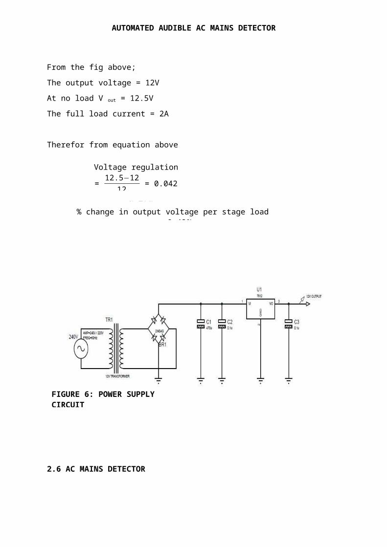
FIGURE 6: POWER SUPPLY CIRCUIT
AUTOMATED AUDIBLE AC MAINS DETECTOR
This detects the AC and convert it to DC for the triggeringstage. The device used here is 12v transformer which detects220V or 240V, it steps down these voltage to 12V, thenconnected to a rectifier and to a voltage regulator, thefilter capacitor remove some repels of AC in other wordssmoothing the voltage.
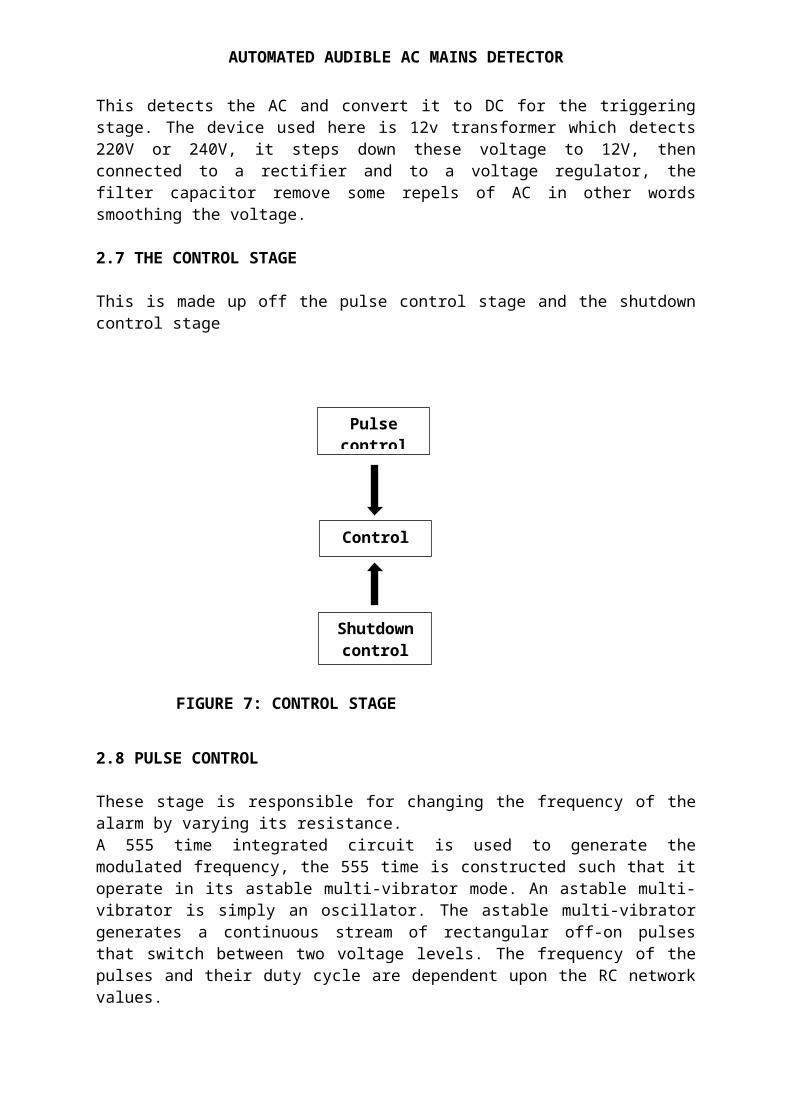
2.7 THE CONTROL STAGE
This is made up off the pulse control stage and the shutdowncontrol stage
2.8 PULSE CONTROL
These stage is responsible for changing the frequency of thealarm by varying its resistance.A 555 time integrated circuit is used to generate themodulated frequency, the 555 time is constructed such that itoperate in its astable multi-vibrator mode. An astable multi-vibrator is simply an oscillator. The astable multi-vibratorgenerates a continuous stream of rectangular off-on pulsesthat switch between two voltage levels. The frequency of thepulses and their duty cycle are dependent upon the RC networkvalues.
Controlstage
Shutdowncontrol
Pulsecontrol
FIGURE 7: CONTROL STAGE
AUTOMATED AUDIBLE AC MAINS DETECTOR
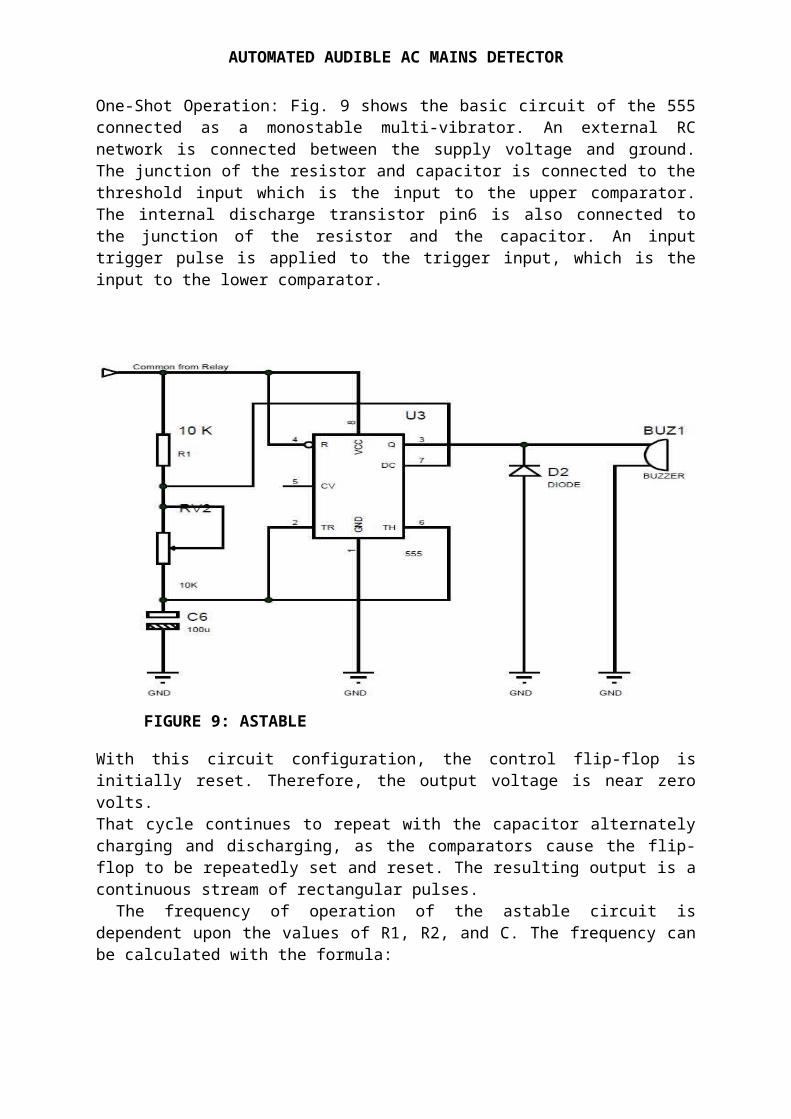
One-Shot Operation: Fig. 9 shows the basic circuit of the 555connected as a monostable multi-vibrator. An external RCnetwork is connected between the supply voltage and ground.The junction of the resistor and capacitor is connected to thethreshold input which is the input to the upper comparator.The internal discharge transistor pin6 is also connected tothe junction of the resistor and the capacitor. An inputtrigger pulse is applied to the trigger input, which is theinput to the lower comparator.
With this circuit configuration, the control flip-flop isinitially reset. Therefore, the output voltage is near zerovolts. That cycle continues to repeat with the capacitor alternatelycharging and discharging, as the comparators cause the flip-flop to be repeatedly set and reset. The resulting output is acontinuous stream of rectangular pulses. The frequency of operation of the astable circuit isdependent upon the values of R1, R2, and C. The frequency canbe calculated with the formula:
FIGURE 9: ASTABLE
AUTOMATED AUDIBLE AC MAINS DETECTOR
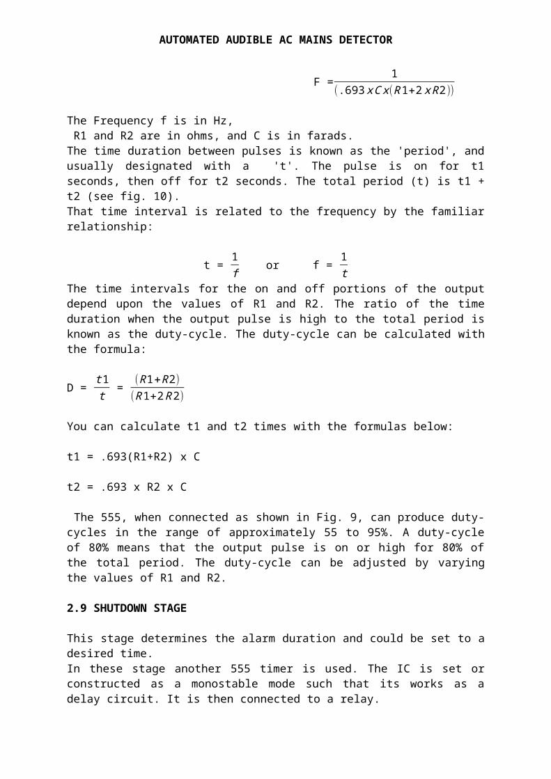
F = 1(.693xCx(R1+2xR2))
The Frequency f is in Hz, R1 and R2 are in ohms, and C is in farads. The time duration between pulses is known as the 'period', andusually designated with a 't'. The pulse is on for t1seconds, then off for t2 seconds. The total period (t) is t1 +t2 (see fig. 10). That time interval is related to the frequency by the familiarrelationship:
t = 1f or f = 1t
The time intervals for the on and off portions of the outputdepend upon the values of R1 and R2. The ratio of the timeduration when the output pulse is high to the total period isknown as the duty-cycle. The duty-cycle can be calculated withthe formula:
D = t1t = (R1+R2)(R1+2R2)
You can calculate t1 and t2 times with the formulas below:
t1 = .693(R1+R2) x C
t2 = .693 x R2 x C
The 555, when connected as shown in Fig. 9, can produce duty-cycles in the range of approximately 55 to 95%. A duty-cycleof 80% means that the output pulse is on or high for 80% ofthe total period. The duty-cycle can be adjusted by varyingthe values of R1 and R2.
2.9 SHUTDOWN STAGE
This stage determines the alarm duration and could be set to adesired time.In these stage another 555 timer is used. The IC is set orconstructed as a monostable mode such that its works as adelay circuit. It is then connected to a relay.
AUTOMATED AUDIBLE AC MAINS DETECTOR
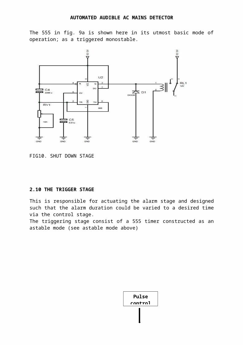
The 555 in fig. 9a is shown here in its utmost basic mode ofoperation; as a triggered monostable.
FIG10. SHUT DOWN STAGE
2.10 THE TRIGGER STAGE
This is responsible for actuating the alarm stage and designedsuch that the alarm duration could be varied to a desired timevia the control stage.The triggering stage consist of a 555 timer constructed as anastable mode (see astable mode above)
Pulsecontrol
AUTOMATED AUDIBLE AC MAINS DETECTOR
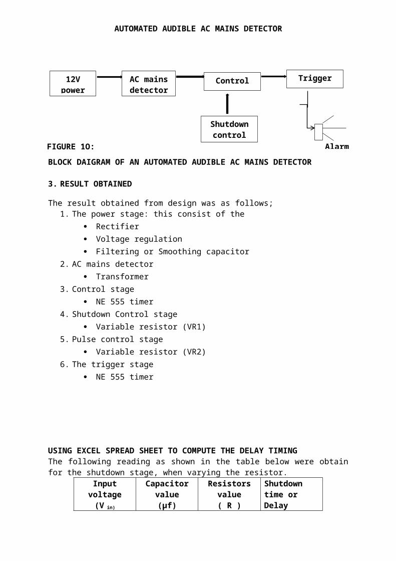
BLOCK DAIGRAM OF AN AUTOMATED AUDIBLE AC MAINS DETECTOR
3. RESULT OBTAINED
The result obtained from design was as follows;1. The power stage: this consist of the
Rectifier Voltage regulation Filtering or Smoothing capacitor
2. AC mains detector Transformer
3. Control stage NE 555 timer
4. Shutdown Control stage Variable resistor (VR1)
5. Pulse control stage Variable resistor (VR2)
6. The trigger stage NE 555 timer
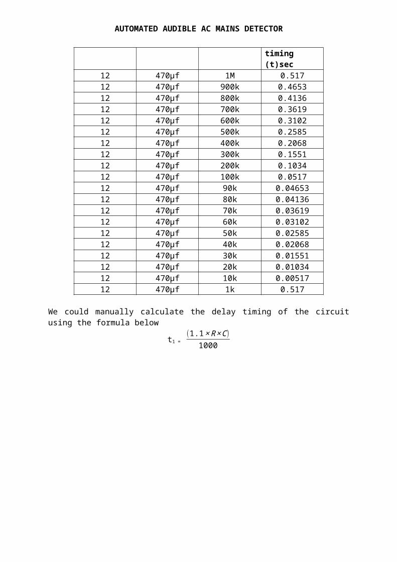
USING EXCEL SPREAD SHEET TO COMPUTE THE DELAY TIMING The following reading as shown in the table below were obtainfor the shutdown stage, when varying the resistor.
Inputvoltage(V in)
Capacitorvalue(µf)
Resistorsvalue( R )
Shutdown time or Delay
12Vpower
AC mainsdetector
Controlstage
Triggerstage
Shutdowncontrol
AlarmFIGURE 1O:
AUTOMATED AUDIBLE AC MAINS DETECTOR
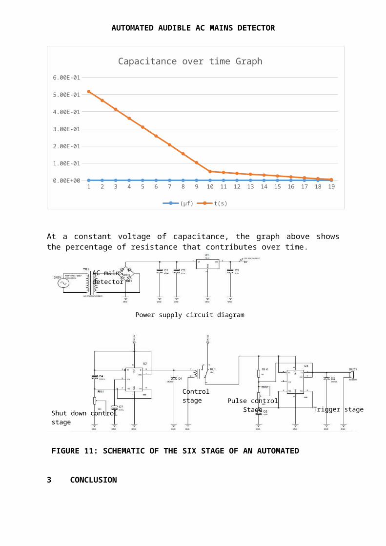
timing (t)sec
12 470µf 1M 0.51712 470µf 900k 0.465312 470µf 800k 0.413612 470µf 700k 0.361912 470µf 600k 0.310212 470µf 500k 0.258512 470µf 400k 0.206812 470µf 300k 0.155112 470µf 200k 0.103412 470µf 100k 0.051712 470µf 90k 0.0465312 470µf 80k 0.0413612 470µf 70k 0.0361912 470µf 60k 0.0310212 470µf 50k 0.0258512 470µf 40k 0.0206812 470µf 30k 0.0155112 470µf 20k 0.0103412 470µf 10k 0.0051712 470µf 1k 0.517
We could manually calculate the delay timing of the circuitusing the formula below
t1 = (1.1×R×C)
1000
AUTOMATED AUDIBLE AC MAINS DETECTOR
1 2 3 4 5 6 7 8 9 10 11 12 13 14 15 16 17 18 190.00E+00
1.00E-01
2.00E-01
3.00E-01
4.00E-01
5.00E-01
6.00E-01
Capacitance over time Graph
(µf) t(s)
At a constant voltage of capacitance, the graph above showsthe percentage of resistance that contributes over time.
3 CONCLUSION
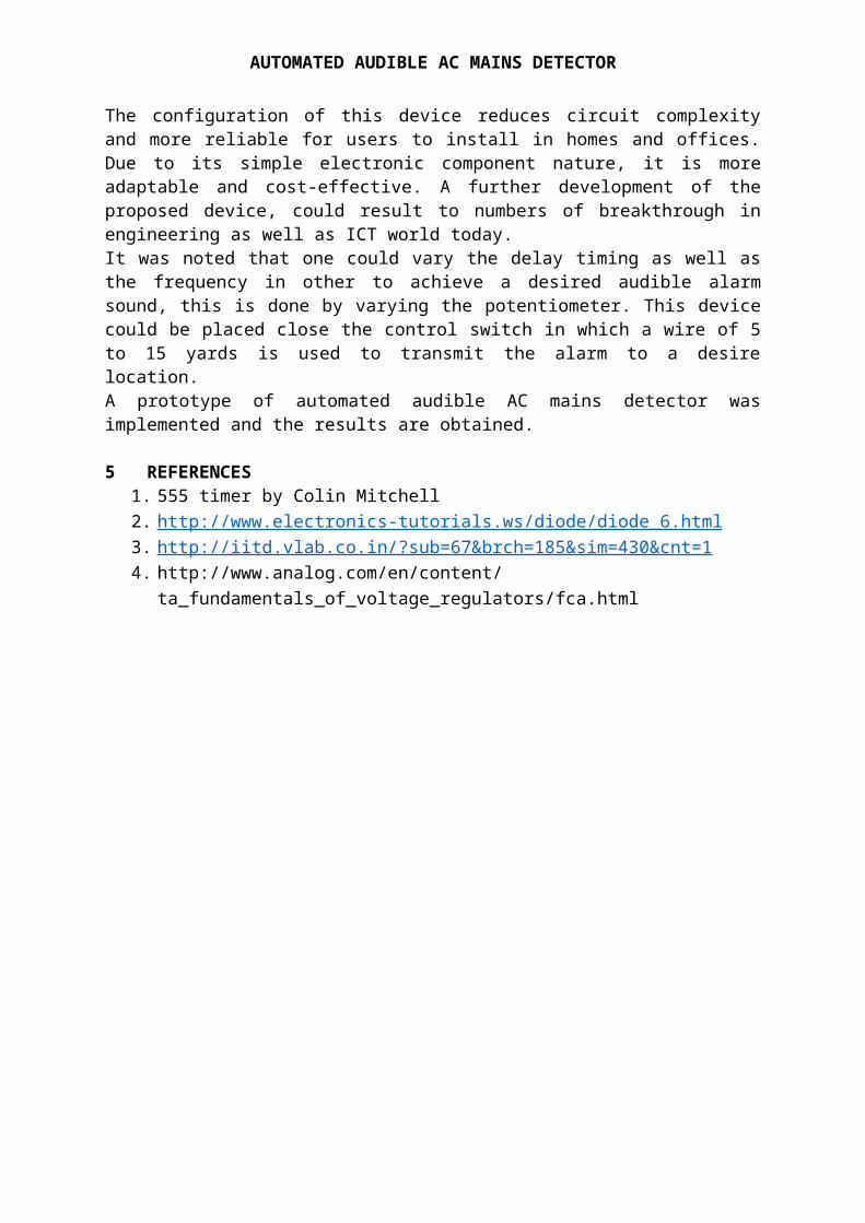
FIGURE 11: SCHEMATIC OF THE SIX STAGE OF AN AUTOMATED
Control stage
Power supply circuit diagram
Trigger stageShut down control stage
Pulse controlStage
AC mains detector
AUTOMATED AUDIBLE AC MAINS DETECTOR
The configuration of this device reduces circuit complexityand more reliable for users to install in homes and offices.Due to its simple electronic component nature, it is moreadaptable and cost-effective. A further development of theproposed device, could result to numbers of breakthrough inengineering as well as ICT world today.It was noted that one could vary the delay timing as well asthe frequency in other to achieve a desired audible alarmsound, this is done by varying the potentiometer. This devicecould be placed close the control switch in which a wire of 5to 15 yards is used to transmit the alarm to a desirelocation.A prototype of automated audible AC mains detector wasimplemented and the results are obtained.
5 REFERENCES 1. 555 timer by Colin Mitchell2. http://www.electronics-tutorials.ws/diode/diode_6.html 3. http://iitd.vlab.co.in/?sub=67&brch=185&sim=430&cnt=1 4. http://www.analog.com/en/content/
ta_fundamentals_of_voltage_regulators/fca.html