Embed Size (px)
Citation preview
A. Campilho and M. Kamel (Eds.): ICIAR 2006, LNCS 4142, pp. 317 – 328, 2006. © Springer-Verlag Berlin Heidelberg 2006
Automatic 3D Face Feature Points Extraction with Spin Images
Cristina Conde, Licesio J. Rodríguez-Aragón, and Enrique Cabello
Universidad Rey Juan Carlos (ESCET), C/Tulipán s/n,
28933 Móstoles, Spain [email protected]
http://frav.escet.urjc.es
Abstract. We present a novel 3D facial feature location method based on the Spin Images registration technique. Three feature points are localized: the nose tip and the inner corners of the right and left eye. The points are found directly in the 3D mesh, allowing a previous normalization before the depth map calcu-lation. This method is applied after a preprocess stage where the candidate points are selected measuring curvatures on the surface and applying clustering techniques. The system is tested on a 3D Face Database called FRAV3D with 105 people and a widely variety of acquisition conditions in order to test the method in a non-controlled environment. The success location rate is 99.5% in the case of the nose tip and 98% in the case of eyes, in frontal conditions. This rate is similar even if the conditions change allowing small rotations. Results in more extremely acquisition conditions are shown too. A complete study of the influence of the mesh resolution over the spin images quality and therefore over the face feature location rate is presented. The causes of the errors are discussed in detail.
1 Introduction
During the last years, the biometrics techniques applied to facial verification have suffered a great development, especially those concerning 2D facial verification [1]. Promising results on images have been obtained but mainly in a constraint acquisition environment. Very well known limitations are lighting and pose changes that largely decrease the success verification rate.
It has been recently when a less expensive and more accurate 3D acquisition de-vices have opened a more common use. Main advantage of 3D data verification is to be independent from lighting conditions and on the other hand huge geometrical in-formation given, so it is possible to make a very precise data normalization. Past years several reviews on the current status of these techniques have been written [2] [3].
An especially relevant step in any 3D face verification system is normalization, be-cause incorrectly normalized data provoke poor final results. To succeed on this stage it is necessary to find the facial feature points that can be used as control points on the normalization work. The automatic location of these feature points is still being an open issue.

318 C. Conde, L.J. Rodríguez-Aragón, and E. Cabello
A method based on Spin Images [4] proposed here finds the face feature points automatically and is intended to be integrated into a 3D face verification system. Despite the great computational efforts that are needed to handle 3D data, we have found that our algorithm is fast enough to fulfill our requirements.
This method has been tested on a 105 people 3D face database. It is called the FRAV3D [5] and has been acquired by the FRAV research group in the Rey Juan Carlos University in Spain. This database contains different acquisition conditions respecting pose and expression. It is available for the research community.
The remainder of the paper is organized as follows. Section 2 describes some pre-vious work made in the face feature location topic. The database used in this paper is described in section 3. The feature location and normalization method is presented in section 4. The experimental results are shown in section 5 and the last section presents several conclusions that can be achieved from this work.
2 Previous Work
The identification of feature points for 2D face recognition is a very well studied problem [6]. 3D facial feature extraction is a relatively new area of research. Colbry et al. [7] found the anchor points in depth map images by calculating the shape index, that contains local curvature information, and applying a statistical face feature model. They obtained a success rate of 99% over frontal faces and an 86% over pose and expression variations. Lu et al. [8] proposed other approach based on the shape index too. They combined 5 face scans of each face to generate a 3D model. Based on the shape index value, the inside eye corner was located and, applying a facial model with relative distances between features, the nose tip and the outer eye corner were found too. This had the advantage that both eyes need not to appear in the scanned data. This method was applied to a small face database of 18 persons with different poses, expressions and lighting conditions. Irfanoglu et al. [9] found automatically ten landmark points in the face based on curvatures and a reference mesh with the land-mark points manually located. The system was tested in the 3D RMA Face Database [10] just in the first session, with 30 people and 3 shots per person.
Gordon et al. [11] used curvatures but calculating it analytically over the three-dimensional surface representing the face. They used a 24 scanned examples face database.
Another different approach if the texture information is available is to register it with the 3D data and find the feature points using the 2D image. Boehnen et al. [12] applied this method to the UND Face Database [13]. They obtained a 99.6% of success rate but only with frontal images. Wang et al. [14] used the 2D and 3D data combined. The 2D facial features were located using a Gabor Filter and the point signature method on 3D data. The method was tested with a 50 people face database. Xiao et al. [15] combined 2D active appearance models and 3D morphable models to track the face moving in a video.
Finally Lee et al. [16] extracted three curvatures, eight invariant facial points and their relative features by a profiles method. They obtained different curve profiles by the intersection between the data and different planes, and analyzing the curvature of
Automatic 3D Face Feature Points Extraction with Spin Images 319
these profiles the eight facial feature points were obtained. Several tests were done using a 100 people face database with only frontal images.
One of the main advantages of the method presented on this paper is that it can be directly applied over a 3D mesh, which allows a previous normalization and the building of an optimal depth map or range data.
On the other hand the system has been tested on a real database with several indi-viduals and even more important over a great variety of acquisition terms.
3 Face Database
The 3D face database used for testing the system is the so-called FRAV3D. A scanner MINOLTA�VIVID-700 laser light-stripe triangulation range finder was used capable to generate both, a 3D set of points organized in a triangular mesh and a 2D colour image.
Data were collected under laboratory controlled conditions including an indoor stage without daylight illumination. Dim spotlights were used except for data cap-tured under light variations, something that would be seen later on, in which zenithal direct illumination was employed.
The database contains data from 105 Caucasian subjects (81 males/24 women) all of them adults. The acquisition process took 10 months, from September 2004 to June 2005, and each individual participated in one complete acquisition session. All acqui-sitions were taken with closed eyes for safety reasons, though the scanner guarantied no harm. No hats, scarfs or glasses were allowed.
16 acquisitions were taken from each individual included in our database. An ac-quisition protocol was discussed and established to keep conditions as well as image standardization controlled. The sequence of acquisitions was generated in such way that only one perturbation parameter was included at each stage, varying this parame-ter from one acquisition to the next. By doing so, we obtained the required variability between images affected by the same perturbation.
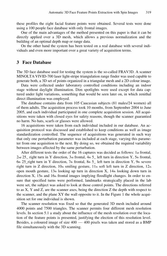
After different tests the order of the 16 captures was decided as follows: 1st frontal, 2nd 25_ right turn in Y direction, 3rd frontal, 4th 5_ left turn in direction Y, 5th frontal, 6th 25_right turn in Y direction, 7th frontal, 8th 5_ left turn in direction Y, 9th severe right turn in Z direction, 10th smiling gesture, 11th soft left turn in Z direction, 12th open mouth gesture, 13th looking up turn in direction X, 14th looking down turn in direction X, 15th and 16th frontal images implying floodlight changes. In order to en-sure that specified turns were performed, landmarks strategically placed in the lab were set, the subject was asked to look at those control points. The directions referred to as X, Y and Z, are the scanner axes, being the direction Z the depth with respect to the scanner, and the plane XY the wall opposite to it. In the Figure 1 the whole acqui-sition set for one individual is shown.
The scanner resolution was fixed so that the generated 3D mesh included around 4000 points and 7500 triangles. The scanner permits four different mesh resolution levels. In section 5.1 a study about the influence of the mesh resolution over the loca-tion of the feature points is presented, justifying the election of this resolution level. Besides, a coloured image of size 400 −− 400 pixels was taken and stored as a BMP file simultaneously with the 3D scanning.
320 C. Conde, L.J. Rodríguez-Aragón, and E. Cabello
Some parts of the FRAV3D database are available at the web page [5] and the whole database is available upon request. Both VRML files and BMP coloured im-ages are available.
Fig. 1. From left to right, top to bottom, the acquisition sequence of a subject is displaced. Both BMP color images and VRML 3D meshes are shown.
3.1 Acquisition Problems
During the acquisition period two main problems were detected: areas where the laser signal is lost, carving holes, and noise in the laser signal producing peaks.
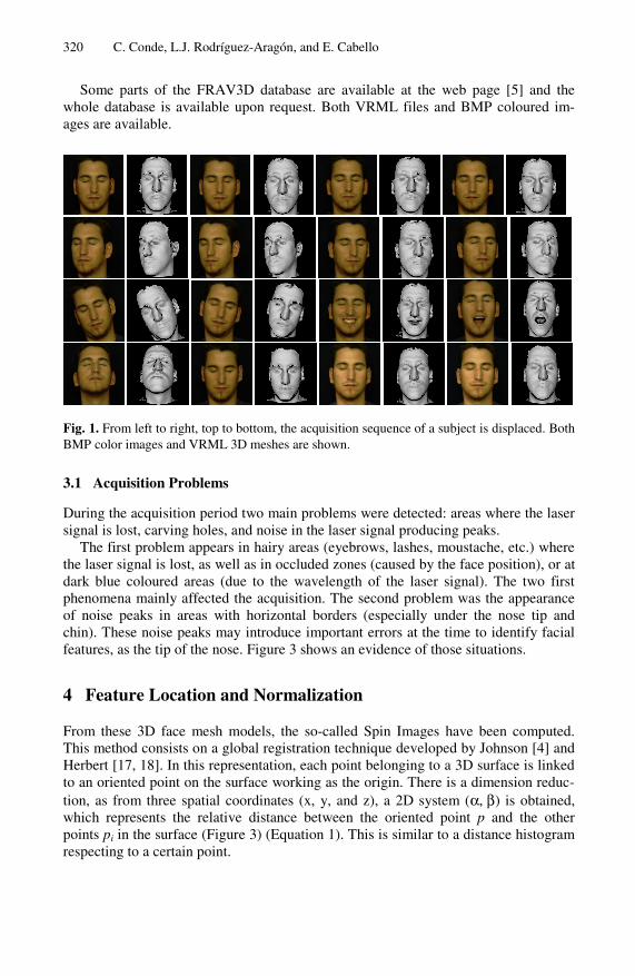
The first problem appears in hairy areas (eyebrows, lashes, moustache, etc.) where the laser signal is lost, as well as in occluded zones (caused by the face position), or at dark blue coloured areas (due to the wavelength of the laser signal). The two first phenomena mainly affected the acquisition. The second problem was the appearance of noise peaks in areas with horizontal borders (especially under the nose tip and chin). These noise peaks may introduce important errors at the time to identify facial features, as the tip of the nose. Figure 3 shows an evidence of those situations.
4 Feature Location and Normalization
From these 3D face mesh models, the so-called Spin Images have been computed. This method consists on a global registration technique developed by Johnson [4] and Herbert [17, 18]. In this representation, each point belonging to a 3D surface is linked to an oriented point on the surface working as the origin. There is a dimension reduc-tion, as from three spatial coordinates (x, y, and z), a 2D system (α, β) is obtained, which represents the relative distance between the oriented point p and the other points pi in the surface (Figure 3) (Equation 1). This is similar to a distance histogram respecting to a certain point.
Automatic 3D Face Feature Points Extraction with Spin Images 321
Fig. 2. Acquisition problems: top row, lost points; down row noise effects
The Spin-map S0 components can be computed as follows:
))(,))(((),()(
:
22
0
230
pxnpxnpxx −⋅−⋅−−=→
→
βαS
RRS (1)
Encoding the density of points in the Spin-map, the 2D array representation of a Spin Image can be produced.
Fig. 3. Parameters of Johnson’s geometrical Spin Image [4]
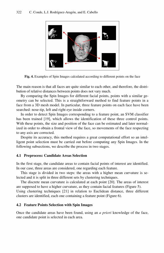
As the Spin images depend on the origin point, different facial points generate par-ticular different images (see Figure 4). We have considered Spin images for the nose-tip and the eyes corners, which provide us with similar images, even for different persons.
322 C. Conde, L.J. Rodríguez-Aragón, and E. Cabello
Fig. 4. Examples of Spin Images calculated according to different points on the face
The main reason is that all faces are quite similar to each other, and therefore, the distri-bution of relative distances between points does not vary much.
By comparing the Spin Images for different facial points, points with a similar ge-ometry can be selected. This is a straightforward method to find feature points in a face from a 3D mesh model. In particular, three feature points on each face have been searched: nose-tip, left and right eye inside corners.
In order to detect Spin Images corresponding to a feature point, an SVM classifier has been trained [19], which allows the identification of these three control points. With these points, the size and position of the face can be estimated and later normal-ized in order to obtain a frontal view of the face, so movements of the face respecting to any axis are corrected.
Despite its accuracy, this method requires a great computational effort so an intel-ligent point selection must be carried out before computing any Spin Images. In the following subsections, we describe the process in two stages.
4.1 Preprocess: Candidate Areas Selection
In the first stage, the candidate areas to contain facial points of interest are identified. In our case, three areas are considered, one regarding each feature.
This stage is divided in two steps: the areas with a higher mean curvature is se-lected and it is split in three different sets by clustering techniques.
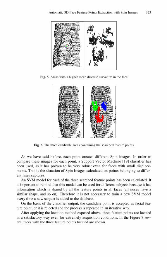
The discrete mean curvature is calculated at each point [20]. The areas of interest are supposed to have a higher curvature, as they contain facial features (Figure 5). Using clustering techniques [21] in relation to Euclidean distance, three different clusters are identified, each one containing a feature point (Figure 6).
4.2 Feature Points Selection with Spin Images
Once the candidate areas have been found, using an a priori knowledge of the face, one candidate point is selected in each area.
Automatic 3D Face Feature Points Extraction with Spin Images 323
Fig. 5. Areas with a higher mean discrete curvature in the face
Fig. 6. The three candidate areas containing the searched feature points
As we have said before, each point creates different Spin images. In order to compare these images for each point, a Support Vector Machine [19] classifier has been used, as it has proven to be very robust even for faces with small displace-ments. This is the situation of Spin Images calculated on points belonging to differ-ent laser captures.
An SVM model for each of the three searched feature points has been calculated. It is important to remind that this model can be used for different subjects because it has information which is shared by all the feature points in all faces (all noses have a similar shape, and so on). Therefore it is not necessary to train a new SVM model every time a new subject is added to the database.
On the basis of the classifier output, the candidate point is accepted as facial fea-ture point, or it is rejected and the process is repeated in an iterative way.
After applying the location method exposed above, three feature points are located in a satisfactory way even for extremely acquisition conditions. In the Figure 7 sev-eral faces with the three feature points located are shown.

324 C. Conde, L.J. Rodríguez-Aragón, and E. Cabello
Fig. 7. Location Results (feature points are brought out). From left to right: a frontal capture, Y axis rotated, smiling and X axis rotated.
5 Results and Discussion
In order to measure the quality of our system and its response over different environ-ments a process of feature location was done separately from each kind of image ac-quired. Table 1 shows the success location percentages of each searched feature point.
It is greater the rate of correct location for nose feature than for eyes feature. This happens because nose has a more remarkable geometry than eyes and also that, con-cerning to eyes, especially if the images are too rotated, it is very usual the occlusion and the point is not even acquired. The greater the turn degree is, the more usual it is. These fails on the data acquisition process are very common, because it was allowed a natural pose towards the camera, with no hair hiding the face or resting the head back. It is necessary a friendly subject, but not in a very uncomfortable environment.
The location system shown here is very robust facing those acquisition fails. As it can be seen in Figure 7, second image from the left (Y axis rotated) the system has been able to locate the searched points though there is a huge area of lost points. On the contrary, it can be seen in Figure 8 an example where the degree turning is such that the location is not possible. On the left image it can be seen the face in the origi-nal acquisition pose, and on the right, the image frontally rotated. It can be seen a great deal of points not acquired, making the eyes unallocated.
Table 1. Success rate feature location in all the acquisition conditions considered
Acquisition Condition Nose Right Eye Left Eye frontal 99.5 97.3 98 5º round Y axis 98.57 96.5 96.4 25º round Y axis 97.2 77.2 73.5 severe turn round Z axis 98.1 88.4 92 soft turn round Z axis 99 96.4 97.1 smiling expression 99.5 96.3 95.3 open mouth expression 98.1 92.1 90.1 looking up turn round X axis 97.2 86 86.2 looking down turn round X axis 99.5 96.3 97.7 frontal images implying floodlight changes 99.2 96.5 97.6
Automatic 3D Face Feature Points Extraction with Spin Images 325
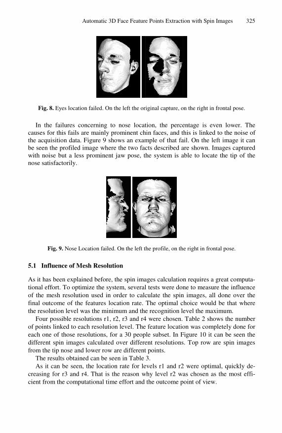
Fig. 8. Eyes location failed. On the left the original capture, on the right in frontal pose.
In the failures concerning to nose location, the percentage is even lower. The causes for this fails are mainly prominent chin faces, and this is linked to the noise of the acquisition data. Figure 9 shows an example of that fail. On the left image it can be seen the profiled image where the two facts described are shown. Images captured with noise but a less prominent jaw pose, the system is able to locate the tip of the nose satisfactorily.
Fig. 9. Nose Location failed. On the left the profile, on the right in frontal pose.
5.1 Influence of Mesh Resolution
As it has been explained before, the spin images calculation requires a great computa-tional effort. To optimize the system, several tests were done to measure the influence of the mesh resolution used in order to calculate the spin images, all done over the final outcome of the features location rate. The optimal choice would be that where the resolution level was the minimum and the recognition level the maximum.
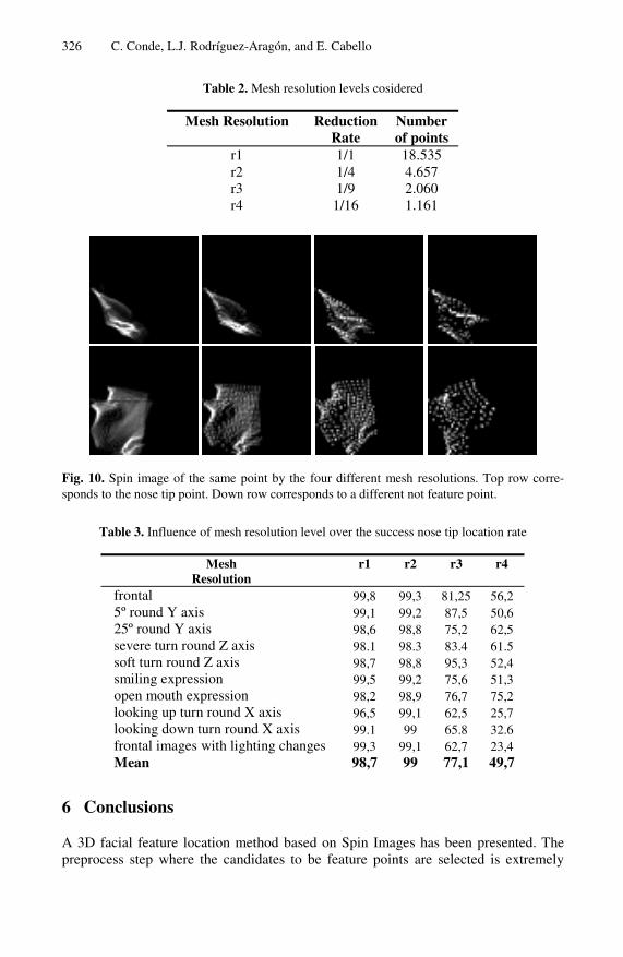
Four possible resolutions r1, r2, r3 and r4 were chosen. Table 2 shows the number of points linked to each resolution level. The feature location was completely done for each one of those resolutions, for a 30 people subset. In Figure 10 it can be seen the different spin images calculated over different resolutions. Top row are spin images from the tip nose and lower row are different points.
The results obtained can be seen in Table 3. As it can be seen, the location rate for levels r1 and r2 were optimal, quickly de-
creasing for r3 and r4. That is the reason why level r2 was chosen as the most effi-cient from the computational time effort and the outcome point of view.
326 C. Conde, L.J. Rodríguez-Aragón, and E. Cabello
Table 2. Mesh resolution levels cosidered
Mesh Resolution Reduction Rate
Number of points
r1 1/1 18.535 r2 1/4 4.657 r3 1/9 2.060 r4 1/16 1.161
Fig. 10. Spin image of the same point by the four different mesh resolutions. Top row corre-sponds to the nose tip point. Down row corresponds to a different not feature point.
Table 3. Influence of mesh resolution level over the success nose tip location rate
Mesh Resolution
r1 r2 r3 r4
frontal 99,8 99,3 81,25 56,2 5º round Y axis 99,1 99,2 87,5 50,6 25º round Y axis 98,6 98,8 75,2 62,5 severe turn round Z axis 98.1 98.3 83.4 61.5 soft turn round Z axis 98,7 98,8 95,3 52,4 smiling expression 99,5 99,2 75,6 51,3 open mouth expression 98,2 98,9 76,7 75,2 looking up turn round X axis 96,5 99,1 62,5 25,7 looking down turn round X axis 99.1 99 65.8 32.6 frontal images with lighting changes 99,3 99,1 62,7 23,4 Mean 98,7 99 77,1 49,7
6 Conclusions
A 3D facial feature location method based on Spin Images has been presented. The preprocess step where the candidates to be feature points are selected is extremely

Automatic 3D Face Feature Points Extraction with Spin Images 327
important because of Spin Images is a powerful tool but with a high computational cost. This preprocess is made by selecting areas with a higher curvature and splitting it in three candidate areas by clustering techniques.
A 3D face database with 105 persons and 16 captures per person, FRAV3D, has been acquired and is available for researching purposes [5]. Both VRML files and BMP coloured images are available.
The feature location method has been tested over a widely variety of acquisition conditions, allowing to check it robustness in a non controlled environment. In the case of frontal images, the results show a 99.5% of nose tip location success rate and about 98% in the eyes location. These results are similar if the acquisition conditions change softly, with small rotations. Especially in the case of severe turns round Y axis, there are occluded areas that decrease largely the eyes location success rate. Looking up rotations affect the success rate too because of the chin and the tip of the nose can be confused.
The results show that the method is relatively independent from acquisition condi-tions except in extreme cases. Its principal advantage is that the feature points are located in the 3D mesh, allowing a previous normalization before the depth map cal-culation, obtaining and optimal representation.
Acknowledgements
This paper has been supported by grants from Rey Juan Carlos University. The au-thors would like to thank Jorge Pérez for his enthusiastic work.
References
1. W. Zhao, R. Chellappa, P.J. Phillips, and A. Rosenfeld: Face Recognition: A Literature Survey. ACM Computing Surveys, Volume 35, Issue 4, December 2003.
2. Kevin W. Bowyer, Kyong Chang, and Patrick Flynn: A Survey of 3D and Multi-Modal 3D+2D Face Recognition. International Conference on Pattern Recognition, August 2004
3. J. Kittler, A. Hilton, M. Hamouz, J. Illingworth.: 3D Assisted Face Recognition: A Survey of 3D imaging, Modelling and Recognition Approaches. IEEE CVPR05 Workshop on Advanced 3D Imaging for Safety and Security. San Diego, CA, 2005.
4. A.E. Johnson. Spin-images: “A representation for 3-D surface matching.” PhD Thesis. Robotics Institute. Carnegie Mellon University. 1997.
5. http://frav.escet.urjc.es/databases/FRAV3D 6. Ming-Hsuan Yang, Kriegman, D.J., Ahuja, N.: Detecting faces in images: a survey. Pat-
tern Analysis and Machine Intelligence, IEEE Transactions on . Volume 24, Issue 1, Jan. 2002 Page(s):34 - 58
7. D. Colbry, G. Stockman and A. Jain: Detection of Anchor Points for 3D Face Verification, Proc. IEEE Workshop on Advanced 3D Imaging for Safety and Security A3DISS, San Diego, CA, June 25, 2005.
8. X. Lu, D. Colbry, and A. K. Jain: Three dimensional model based face recognition, ICPR, Cambridge UK, August 2004.

328 C. Conde, L.J. Rodríguez-Aragón, and E. Cabello
9. Irfanoglu, M.O., Gokberk, B., Akarun, L., 3D shape-based face recognition using auto-matically registered facial surfaces. Pattern Recognition, 2004. ICPR 2004. Proceedings of the 17th International Conference on. Volume 4, 23-26 Aug. 2004 Page(s):183 - 186
10. 3DRMA Face Database. http://www.sic.rma.ac.be/˜beumier/DB/3d rma.html 11. Gordon G.: Face recognition based on depth and curvature features, CVPR, 1992, pp. 108-
110. 12. C. Boehnen and T. Russ.: A fast multi-modal approach to facial feature detection. In
Workshop on Applications of ComputerVision, 2004 13. University of Notre Dame Database.
http://www.nd.edu/~cvrl/UNDBiometricsDatabase.html 14. Y. Wang, C. Chua, Y. Ho: Facial feature detection and face recognition from 2D and 3D
images , Pattern Recognition Letters, vol. 23, no. 10, August 2002, pp. 1191-1202. 15. J. Xiao, S. Baker, I. Mathews, and T. Kanade: Real-time combined 2D + 3D active ap-
pearance models , CVPR, June 2004. 16. Yongjin Lee , Kyunghee Lee and Sungbum Pan: Audio- and Video-Based Biometric Per-
son Authentication: 5th International Conference, AVBPA 2005 Proceedings, pp219, NY, USA, 2005
17. 17.A. E. Johnson, M.Hebert.: Surface matching for object recognition in complex three-dimensional scenes. Image Vision Computing, 1998, 16: 635-651.
18. A. E. Johnson, M.Hebert.: Using Spin Images for efficient object recognition in cluttered 3D scenes. IEEE Trans. PAMI.1999, 21(5): 433-449
19. T. Joachims: Making large-Scale SVM Learning Practical. Advances in Kernel Methods. pp.169 .
20. Tom Lyche and Larry L. Schumaker (eds.): Mathematical Methods for Curves and Sur-faces. Oslo 2000. pp. 135–146.Copyright 2001 by Vanderbilt University Press, Nashville, TN. ISBN 0-8265-1378-6.
21. Sergios Theodoridis and Konstantinos Koutroumbas: Pattern Recognition. Academic Press. 1999. Chapter 11.


