Embed Size (px)
Citation preview

Hindawi Publishing CorporationEURASIP Journal on Embedded SystemsVolume 2007, Article ID 75368, 10 pagesdoi:10.1155/2007/75368
Research ArticleAutomatic Generation of Spatial and Temporal MemoryArchitectures for Embedded Video Processing Systems
Hakan Norell, Najeem Lawal, and Mattias O’Nils
Electronics Design Division, Department of Information Technology and Media, Mid Sweden University, 851 70 Sundsvall, Sweden
Received 1 May 2006; Revised 11 October 2006; Accepted 15 October 2006
Recommended by Heinrich Garn
This paper presents a tool for automatic generation of the memory management implementation for spatial and temporal real-time video processing systems targeting field programmable gate arrays (FPGAs). The generator creates all the necessary memoryand control functionality for a functional spatio-temporal video processing system. The required memory architecture is auto-matically optimized and mapped to the FPGAs’ memory resources thus producing an efficient implementation in terms of usedinternal resources. The results in this paper show that the tool is able to efficiently and automatically generate all required memorymanagement modules for both spatial and temporal real-time video processing systems.
Copyright © 2007 Hakan Norell et al. This is an open access article distributed under the Creative Commons Attribution License,which permits unrestricted use, distribution, and reproduction in any medium, provided the original work is properly cited.
1. INTRODUCTION
In today’s society it is apparent that video systems are gener-ally becoming standard applications. These systems are play-ing a central role in the daily life of the majority of homes.Embedded video applications contained in home entertain-ment systems are becoming more and more complex as is theprocessing required. Real-time streamed video is commonand this places significant constraints on the processing ap-plications as the data rates increase towards high-definitiontelevision (HDTV). Surveillance application is one of themost rapidly developing areas. Video monitoring is nowpresent in almost every store or public place. The amountof video data produced by these systems requires them to beable to efficiently derive features or events that are present inthe scene. This, in turn, has led to an increased requirementto enable more complex operations such as prefiltering, ob-ject recognition, or compression to be performed as close aspossible to the video source. This advance has led to the rapiddevelopment of smart cameras which have the ability to ful-fill these requirements. Complex reconfigurable embeddedsystems with advanced image processing functions must berapidly developed which are also available at a low cost [1].
Video processing systems required in the broadcast andpostprocessing market are typically in the low-volume andhigh-cost segment. These are systems performing real-timehigh-resolution (2048 � 2048@24 fps) high-performance
computation with complex motion compensating spatio-temporal filters [2]. The trend is for the algorithm complex-ity to increase over time. This increased complexity is oftenreflected in the memory usage. One example involves thememory usage required by algorithms with temporal datadependencies. In order to manage the increased complexityand the requirement for a shorter period of time-to-market,efficient toolsets are required. Effective development toolscan abstract the hardware layer and ease the developmentby enabling the systems designer to perform actual hardwareimplementation without extensive hardware knowledge.
Attempts at reducing the time-to-market of modern elec-tronic systems have, in general, increased the motivation todevelop automation tools for system modeling [3–8], opti-mization [9], simulations [3, 10, 11], and synthesis [9, 12–17]. The main objective of these automation tools is to em-power the designer not to only have the ability to cope withincreasing design complexity but also to generate efficient de-signs as quickly as possible. In this paper, we present a designsuite for generating the architecture for real-time spatial andtemporal image/video filters targeting field programmablegate arrays (FPGAs) thus enabling designers to cope with de-sign complexities and time-to-market constraints.
The outline of this paper is as follows. Firstly, relatedwork is presented and then the background and the scopeof this paper are stated. We then present the real-time videoprocessing system (RTVPS) synthesis and limitations in

2 EURASIP Journal on Embedded Systems
Section 4. The results are presented in Section 5 followed bythe discussions and conclusions in Section 6 and Section 7,respectively.
2. RELATED WORK
This work is built on the success of many previous worksin the area of memory estimation, optimization, mapping,memory accessing, and interfacing for both on- and off-chipmemory allocations. However, there is a rather limited selec-tion in the literature of work relating to homogenous toolswhich unify the management of on- and off-chip memoriesin a seamless manner and, additionally, of tools able to han-dle boundary conditions for real-time video processing sys-tems.
Reference [18] presents the design and implementationof a high-level core generator for 2D convolution operations,which contains the parameters and ability to scale in terms ofthe convolution window size and coefficients, the input pixelword length, and the image size. The work has been extendedto be generic and automatically implemented. The allocationof line buffers required by the convolution cores has also beeninvestigated. The work by Schmit and Thomas [19] performsarray grouping (vertically and horizontally) and dimensionaltransformation (array widening and array narrowing). Arraywidening is useful for read-only arrays and those accessed inloops with an unrolled number of iterations. Jha and Dutt[20] presented two algorithms for memory mapping. Thefirst, linear memory mapping, approximates target memoryword-count to the largest power-of-two that is less than orequal to the source memory word-count. The second, ex-haustive memory mapping, assumes that the target memorymodule may have a larger bit-width and word count. Lawalet al. [21] presented a heuristics-based algorithm for allocat-ing FPGA block RAMs for the implementation of RTVPS. Toachieve optimal results, dual port capabilities of block RAMswere exploited and vertical grouping of the line buffers aswell as dynamic allocation of memory objects to multipleblock RAMs were utilised. The effectiveness of the algorithmwas shown through the implementation of realistic imageprocessing systems.
With reference to background memory management,Thornberg et al. [22] proposed a methodology for back-ground memory estimation and optimization. A tool imple-menting the methodology to generate optimized estimatesof the memory requirements of an RTVPS was also pre-sented. Weinhardt and Luk [23] present a technique thatoptimally allocates memory objects to a set of backgroundmemory banks using integer linear programming (ILP). Thetechnique achieved optimisation by parallelisation of dataaccesses through pipelining. Diniz and Park [24] addressedthe problems associated with external memory interfacingby exploiting target memory architecture and the applicationmemory access pattern.
We have taken advantage of these, and other notableworks, in developing the work presented in this paper. Touse the architecture generator presented in this paper, the
designer is only required to specify the memory requirementsof a neighbourhood oriented RTVPS and continue with thedevelopment of the core RTVPS. This work will implementdata storage to both on- and off-chip memories and provideinterface for the pixel data required by the filter. FlexFilm[2] and Imagine [25] are the closest related research worksat the present time. FlexFilm is a top-end multi-FPGA hard-ware/software architecture, for computation intensive, high-resolution real-time digital film processing. The architectureimplements the external memories and achieved record per-formance. However, very little was reported concerning theallocation to on-chip memory. Our work differs from theImagine Stream Architecture since our core processing tech-nology is FPGA.
3. BACKGROUND
This work was developed as part of the IMEM-IMapper de-sign tool [8, 10]. The primary objective is to assist designersin a seamless implementation of neighbourhood-orientedRTVPS filters by handling the memory requirements andboundary conditions of a filter. IMEM is a system descriptiondataflow graph that generates a fully synthesisable real-timeregister-transfer level (RTL) model of a RTVPS. Its basis liesin the knowledge that the filter kernel and the interface andmemory model of a real-time video processing system can bedescribed separately [10]. Parameters extracted from IMEMinclude image size, kernel size, colour-model, and data de-pendencies. Naturally, an RTVPS will consist of several suchfilters, which may possibly contain varying values.
Each set of parameters is the interface and memorymodel generated for each of the filters in RTVPS. The fullmodel also includes interfaces and operators relative to eachother. The IMEM model can be imported into our automaticsynthesis tool IMapper which generates the target-specificimplementation of the interface and memory model. A man-ually refined filter kernel is then merged with the automat-ically generated interface and memory model into target-specific RTL-code. This video system implementation canbe further transformed into gate-level code using a target-specific synthesis tool. Figure 1 shows the relationship be-tween IMEM and IMapper.
This work implements the interface and memory modeland the filter boundary conditions thus freeing up the de-signer to implement the filter. The presented tool includesthe following work.
(i) Automatic allocation of line buffers and frame buffersfor embedded block RAMs and external RAMs, re-spectively.
(ii) Automatic address generation and interfaces for thetwo memory hierarchies (off and on-chip memory).
(iii) Automatic implementation of boundary conditions.(iv) Implementation of parallel access to all pixel data re-
quired in a neighbourhood (spatial or temporal).(v) Provision of a test-bench with valid image streaming
and image capturing for efficient simulation and veri-fication of a customized video processing algorithm.

Hakan Norell et al. 3
Simulationinput stimuli
IMEMconceptual modelling
Functionalsimulation data
Interface andmemory model Filter kernel
RTL-code generation inIMapper
Filter kernel,refined into RTL-
code
Target-specificRTL-code
RTL to gate level synthesis
Targetarchitecture
Figure 1: The IMEM workflow.
Linebuffers
SLWC
Pixelswitch
Windowctrl.
...
VDMC
External SS/SDRAM
VIP algorithm Sync.
Figure 2: Architectural overview.
4. RVTPS SYNTHESIS
As described in the previous section, the designer speci-fies the required system parameters derived from either theIMEM environments or with parameters derived from an-other source. From these parameters, the IMapper createsthe required hardware structure as depicted in Figure 2. Thearchitecture is derived from three major parts, the slidingwindow controller (SLWC), video data memory controller(VDMC), and the synchronisation block. To ease the imple-mentation of a custom filter function, an HDL template pro-viding the necessary interface for seamless integration in thedesign flow is generated. To illustrate the architecture in de-tail, each of the subparts is presented in the following sec-tions.
4.1. Memory allocation
Almost all image neighbourhood operations using either acontinuous or block wise pixel flow are processed by using a
sliding window. Line buffers are required to store the neces-sary data in the spatial neighbourhood.
They are implemented using global memory object(GMO) architecture [26]. For each operator in the neigh-bourhood-oriented RTVPS, GMO can be achieved through
WRi = nlines �wp, (1)
where WRi is the width of the GMO, nlines is the number ofrequired memory objects for an operator, and wp is the bitwidth representing a pixel.
The length of the GMO is equal to that of the memoryobjects forming it [26]. GMOs require a minimal number ofmemory entities in comparison to the direct mapping archi-tecture. Consequently, the number of memory accesses foran RTVPS operation is minimal for a GMO.
Implementing GMOs and their allocation to block RAMsrequires an efficient algorithm so that accessing the allocateddata and reconstructing the line buffers occurs in a seam-less manner with minimal overhead resource and low latency.Two allocation algorithms (one optimized for heuristics [21]and the other for ILP [22]) have been developed and im-plemented for this purpose. The algorithm in [21] createsthe GMOs based on (1). It partitions the GMOs to ensurethat their widths conform to those specified by the FPGAthus ensuring optimal usage of the block RAMs. The algo-rithm takes advantage of the dual port capabilities of theblock RAMs to achieve optimal allocations and the possibil-ity of allocating a GMO to as many block RAMs as required.Figure 3 depicts the method used by the algorithm to allo-cate four memory objects according to the GMO architec-ture. In Figure 3(a), the four line buffers were grouped to-gether to form one GMO. Assuming the GMO is 640-pixelwide, then if it were to be allocated on a Xilinx Spartan 3FPGA, it would require partitioning into two segments, ofwidths 32 and 16, as it is not possible to have a data pathwidth of 48 on a Xilinx Spartan 3 FPGA. In addition, sinceeach block RAM is 16 Kibit (excluding parity feature), thefirst segment, of width 32, would require 2 block RAMs, thuscreating two partitions. The second segment would requirea single partition on a block RAM. Figure 3(b) illustrates thepartitioning of the GMO while Figure 3(c) shows how theGMO is allocated to two block RAMs using a data path of32 bits and 16 bits. The main objective of the allocation algo-rithm is to minimise block RAM usage. This is achieved inFigure 3 since two block RAMs were used as opposed to thefour block RAMs required for the direct mapping of the fourline buffers. With direct mapping, we refer to memory map-ping in which each line buffer is allocated to one block RAM,without resource sharing. In the figure op, seg, par, and BRrepresent the operator, segment, partition, and block RAMnumbers, respectively, and where Ports A and B are the twoio-ports available on a block RAM configured as a dual port(BR2). In this case only Port A is used on a block RAM con-figured as single port (BR1). In [27], two possible approachesfor accessing and reconstructing the allocated memory ob-jects were presented and compared.
The implemented GMO takes the form of a circularbuffer allocated to a set of memory locations. The example

4 EURASIP Journal on Embedded Systems
L� 12
L� 12
L� 12
L� 12
L� 48
Ri
op id = 1
(a)
op = 1 seg = 2 par = 1640� 16
512� 32
op = 1 seg = 1
par = 1
Allocation 128�32
op = 1seg = 1par = 2
640� 48
op = 1
(b)
512� 32
op = 1 seg = 1
par = 1
Port A BR1
Unused memory 2 kBit
op = 1 seg = 2 par = 1
640� 16
Port A BR2 Port B
128�32
op = 1seg = 1par = 2
(c)
Figure 3: Implementation of memory architecture.
in Figure 4 depicts a set of eight memory locations, n � 8 ton � 1, which are indexed by a pointer in a modulus-8 or-der. For every pointer position, pixel data Pn�8 is firstly readand then pixel data Pn is written. The benefit of the Xilinxblock RAM is that it allows first-read-then-write operationto be executed in one single clock cycle. In the continuouscase of a sliding window the mask window will overlap theimage under processing when the border is reached, creatinga boundary condition, as shown in Figure 5.
For each mask window, b possible numbers of bound-ary sets are required to be handled, depending on how manymask positions fall outside the image perimeter. An exam-ple of a boundary set is shown as a dark grey shaded area inFigure 5:
b = 4 �[
(ω � 1)2
2�
ω � 12
]. (2)
Equation (2) holds true, provided that ω � width(I) and ωis an odd number, where ω is the window width and I theimage under processing, according to Figure 5.
For each separate boundary, care has to be taken in orderto prevent the introduction of nonvalid data. With nonvaliddata, we refer to undefined or extreme values that would cor-rupt or bias the following processing functions. Positions inthe window not filled by correct data can be expressed as aset, B �W � IC , where W is the desired processing windowand I the image under processing, according to Figure 5.
For each boundary, the set B is filled with pixels accordingto B � wc, where wc can be configured to originate from thevalid central spatial pixel, inside the image, of the window W ,defined in (3), or for the processing function suitable value:
wc =W(ω + 1
2,ω + 1
2
). (3)
From these boundary conditions, a boundary state controller(BSC) is generated, which provides the necessary control sig-
Pn�8 Pn�7
Pn�6
Pn�5
Pn�4Pn�3
Pn�2
Pn�1
Current pointerposition
incremented atevery clock cycle
After read,write pixel Pn
Firstly,read pixel Pn�8
Figure 4: Read-write cycle.
nals for the spatial or temporal window buffers. The con-troller monitors the inputted vertical and horizontal syn-chronisation signals and keeps track of the window positionrelative to the image boundary. If a boundary is within thewindow, each pixel, falling outside the image, is replaced. Thecontroller and the required line buffers form the temporalarchitecture. An example of an architecture which has a tem-poral depth of n frames is depicted in Figure 6.
The structure of the line buffers that provide the slidingwindow is created by block RAMs, allocated according to themethod previously described. Line buffers are instantiatedaccording to the requirement in the specification and formthe spatial pixel buffer which has two lines in the exampledepicted in Figure 7.
The BSC is generated from generic expressions whichcontain the rules for the operations requiring to be per-formed when an image boundary is reached. At this point,the controller determines which positions in the filter maskmust be replaced.

Hakan Norell et al. 5
W
ω
I
Width
Hei
ght
� � �
. . ....
Figure 5: Illustration of boundary condition.
1
2
3
Boundarystate
control
. . . St=2n+1
St=1
St=0
. . .
� � �
. . .
1. Synchronization and control
2. Temporal pixel data
3. Temporal windows
Figure 6: Temporal buffer architecture for n frames.
The control signals generated in the BSC are fed into theline buffer and are utilized by a pixel switch. The replacementis performed in the boundary pixel switch, at which the de-fault boundary values can be chosen to originate from eitheran external constant or an existing mask position as depictedin Figure 7.
4.2. Temporal memory controller architecture
The architecture generator supports static random accessmemories (SRAMs) in addition to synchronous dynamicrandom access memories (SDRAMs). The choice of mem-ory technology is mainly dependent on the type of systemto be implemented. SRAMs are suitable for video process-ing systems with a nonpredictable read-write access pattern,for example, block search, due to the internal design thateliminates latency between read and write cycles. For stream-oriented applications, such as filter applications with regularread and write patterns, SDRAMs are suitable.
Read and write accesses can be performed in burst modeand scheduled to optimize the related penalties. Limita-tions associated with the two memory types are presented inSection 4.3. The physical memory controller is interchange-able with the memory controller generated by the memoryinterface generator MIG from Xilinx [12]. This enables sim-
1
2
3
...
4
Line 1
Line 2
Boundary pixel sw.
Default bundary values
P9
P6
P3
P8
P5
P2
P7
P4
P1
1. Mask and line control2. Serial pixel data3. Window mask4. Default boundary input
Figure 7: Line buffer architecture.
FrmCnt
RW addr
PAT
+
Glue logic
PhyMemCtrl
4
1 : N
Fifo 0
Fifo 1...
Fifo n� 1
Fifo n
Fifo W
MemSyncCtrl
1
2
3
1. Temporal pixel data2. Processed data3. Syncronization4. Physical memory interface
Figure 8: Video data memory controller (VDMC).
ple and seamless migration to other memory types if re-quired. The read and write patterns stored in the physical ad-dress table (PAT) can be configured during compile time. Ad-dress generation is managed by configurable counters. Theaddress space is derived from the input video stream char-acteristics, image width and height. In order to synchronisedata, a FIFO buffer is implemented for each required tempo-ral level. The size of each buffer depends on the read-writepattern and the number of temporal levels used. The de-scribed architecture is depicted in Figure 8.
The total amount of block RAM available is 432 Kibit dis-tributed on 24 18 Kibit blocks for a Spartan 3 1000. Using
6 EURASIP Journal on Embedded Systems
�103
10
9
8
7
6
5
4
3
2
1
0
Max
imu
mim
age
wid
th(p
ixel
s)
1 3 5 7 9
Frame depth
3� 35� 5
7� 79� 9
Figure 9: Maximum buffer length.
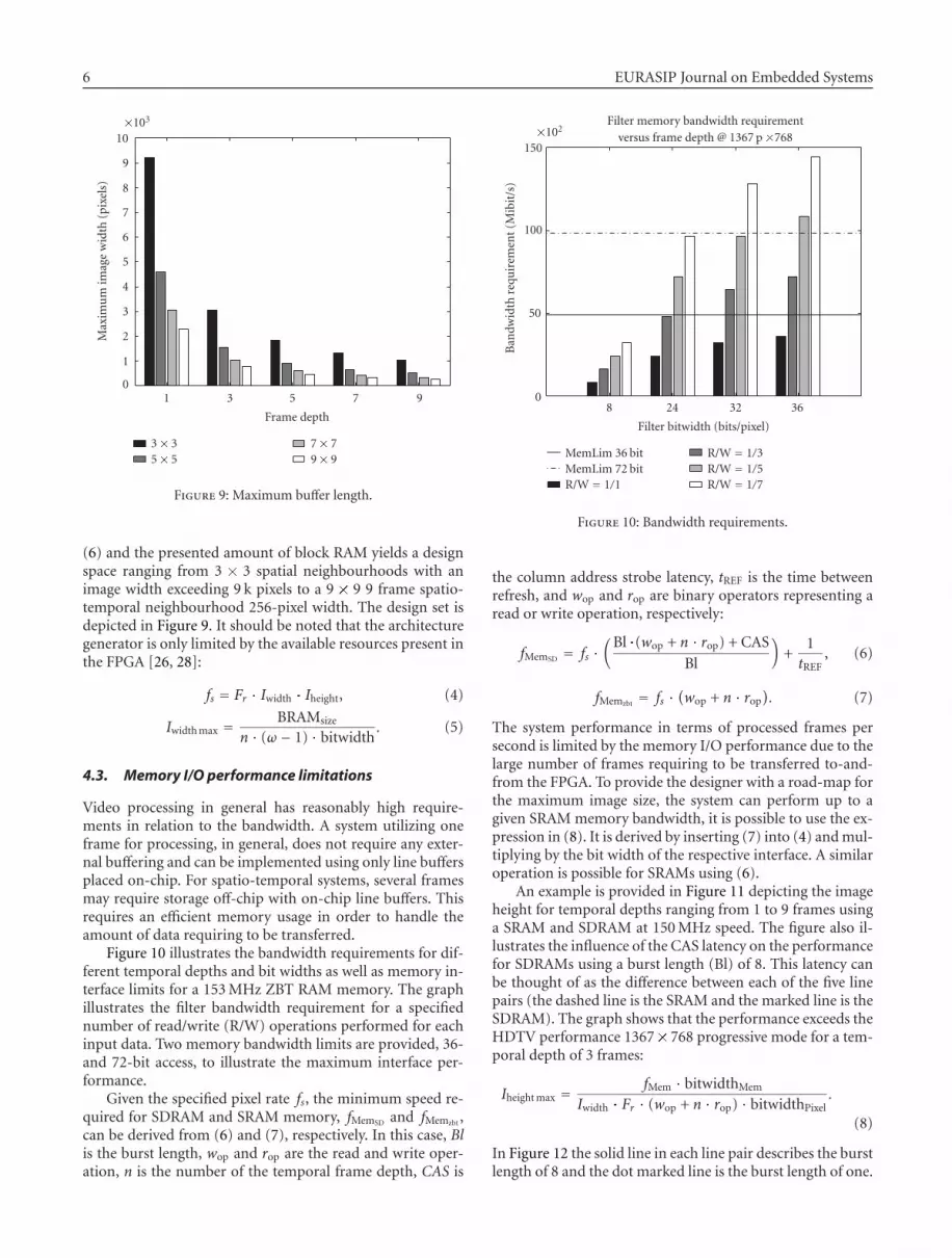
(6) and the presented amount of block RAM yields a designspace ranging from 3 � 3 spatial neighbourhoods with animage width exceeding 9 k pixels to a 9 � 9 9 frame spatio-temporal neighbourhood 256-pixel width. The design set isdepicted in Figure 9. It should be noted that the architecturegenerator is only limited by the available resources present inthe FPGA [26, 28]:
fs = Fr � Iwidth � Iheight, (4)
Iwidth max = BRAMsize
n � (ω� 1) � bitwidth. (5)
4.3. Memory I/O performance limitations
Video processing in general has reasonably high require-ments in relation to the bandwidth. A system utilizing oneframe for processing, in general, does not require any exter-nal buffering and can be implemented using only line buffersplaced on-chip. For spatio-temporal systems, several framesmay require storage off-chip with on-chip line buffers. Thisrequires an efficient memory usage in order to handle theamount of data requiring to be transferred.
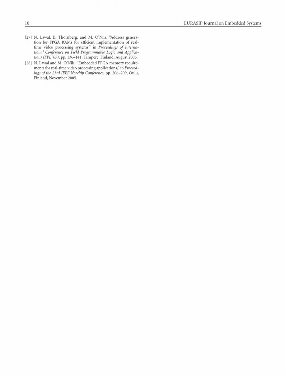
Figure 10 illustrates the bandwidth requirements for dif-ferent temporal depths and bit widths as well as memory in-terface limits for a 153 MHz ZBT RAM memory. The graphillustrates the filter bandwidth requirement for a specifiednumber of read/write (R/W) operations performed for eachinput data. Two memory bandwidth limits are provided, 36-and 72-bit access, to illustrate the maximum interface per-formance.
Given the specified pixel rate fs, the minimum speed re-quired for SDRAM and SRAM memory, fMemSD and fMemzbt ,can be derived from (6) and (7), respectively. In this case, Blis the burst length, wop and rop are the read and write oper-ation, n is the number of the temporal frame depth, CAS is
Filter memory bandwidth requirementversus frame depth @ 1367 p �768�102
150
100
50
0
Ban
dwid
thre
quir
emen
t(M
ibit
/s)
8 24 32 36
Filter bitwidth (bits/pixel)
MemLim 36 bitMemLim 72 bitR/W = 1/1
R/W = 1/3R/W = 1/5R/W = 1/7
Figure 10: Bandwidth requirements.
the column address strobe latency, tREF is the time betweenrefresh, and wop and rop are binary operators representing aread or write operation, respectively:
fMemSD = fs �(Bl �(wop + n � rop) + CAS
Bl
)+
1tREF
, (6)
fMemzbt = fs �(wop + n � rop
). (7)
The system performance in terms of processed frames persecond is limited by the memory I/O performance due to thelarge number of frames requiring to be transferred to-and-from the FPGA. To provide the designer with a road-map forthe maximum image size, the system can perform up to agiven SRAM memory bandwidth, it is possible to use the ex-pression in (8). It is derived by inserting (7) into (4) and mul-tiplying by the bit width of the respective interface. A similaroperation is possible for SRAMs using (6).
An example is provided in Figure 11 depicting the imageheight for temporal depths ranging from 1 to 9 frames usinga SRAM and SDRAM at 150 MHz speed. The figure also il-lustrates the influence of the CAS latency on the performancefor SDRAMs using a burst length (Bl) of 8. This latency canbe thought of as the difference between each of the five linepairs (the dashed line is the SRAM and the marked line is theSDRAM). The graph shows that the performance exceeds theHDTV performance 1367� 768 progressive mode for a tem-poral depth of 3 frames:
Iheight max = fMem � bitwidthMem
Iwidth � Fr � (wop + n � rop) � bitwidthPixel.
(8)
In Figure 12 the solid line in each line pair describes the burstlength of 8 and the dot marked line is the burst length of one.

Hakan Norell et al. 7
Max height for available BW versus frame depth h�102
20
18
16
14
12
10
8
6
4
2
0
Imag
eh
eigh
tfo
rSR
AM
(das
hed
)SD
RA
M
(sol
idm
arke
d)Bl=
815
0M
Hz
@32
bit
BW
(pix
els)
10 11 12 13 14 15 16 17 18 19 20
�102Image width (pixels)
Frames = 1Frames = 3Frames = 5
Frames = 7Frames = 9
CAS latency
Figure 11: Image height versus temporal depth.
This shows that a low-burst length severely degrades the per-formance for low-frame depths. The selected type of memorymainly depends on the application. Generally static memo-ries have a low density compared to that of the correspondingdynamic, which implies a high cost (area).
5. IMPLEMENTATION RESULTS
All parts of the architecture depicted in Figure 2 and Figures13–15 have been implemented and the synthesis results us-ing Xilinx integrated software environment (ISE) version 8.1itargeting the Xilinx Spartan 3 1000 FPGA are shown. Sev-eral results exceeded the resources available on one FPGAchip and hence led to the use of multiple chips. The figuresshow the results for 3 � 3, 5 � 5, and 7 � 7 spatial neigh-bourhoods implemented on 1-, 3-, 5-, 7-, and 9-frame tem-poral neighbourhoods. Figure 13 shows the number of slicesand flip-flops. Figures 14 and 15 display the number of re-quired block RAMs and maximum frequency, respectively.The results were obtained for a resolution of 1367�768, with24 bits per pixel. Table 1 shows the resources required by allthe components in Figure 2 apart from the filter core and theexternal SDRAM used to support the implementation of afilter with 3 � 3 spatial and a 7-frame temporal neighbour-hood.
6. DISCUSSION
The results show that resources increase linearly with the di-mensions of the spatial and temporal neighbourhoods andthat the maximum frequency decreases with the dimensions.This architecture greatly reduces the designer’s developmenttime, increasing productivity and reducing time-to-market,
Max height for available BW (Bl = 1 and 8)versus frame depth h�102
18
16
14
12
10
8
6
4
2
0
Imag
eh
eigh
tfo
rSD
RA
MBl=
8an
d
Bl=
1,15
0M
Hz
@32
bit
BW
(pix
els)
10 11 12 13 14 15 16 17 18 19 20�102
Image width (pixels)
Bl = 8, frame depth (FD) 1, 3, 5, 7, 9 relative bottomBl = 1, frame depth (FD) 1, 3, 5, 7, 9 relative bottom
FD = 1
FD = 3
FD = 5
FD = 9 FD = 7
Figure 12: Burst length influence.
Synthesis results Spartran-3 1000�104
5
4.5
4
3.5
3
2.5
2
1.5
1
0.5
0
Res
ourc
eu
sage
Slices3� 3
FF3� 3
Slices5� 5
FF5� 5
Slices7� 7
FF7� 7
Spatial neighbourhood
Frames = 1Frames = 3Frames = 5
Frames = 7Frames = 9
Figure 13: Synthesis results.
while, at the same time, providing efficient hardware mod-ules. The generic nature of this architecture makes it subjec-tive to the core filter algorithm rather than constraining it.Hence it is only necessary for the designers to define the in-terfaces required by the filter, implement the filter, and spec-ify the required memory parameter. The architecture genera-tor then generates the modules (as indicated in Figure 2) nec-essary to manage the filter data requirements.

8 EURASIP Journal on Embedded Systems
Synthesis results Spartran-3 1000120
100
80
60
40
20
0
Req
uir
edn
um
ber
ofbl
ock
RA
Ms
3� 3 5� 5 7� 7
Spatial neighbourhood
Frames = 1Frames = 3Frames = 5
Frames = 7Frames = 9
Figure 14: Block RAM requirements.
Synthesis results Spartran-3 1000140
120
100
80
60
40
20
0
Freq
uen
cy(M
Hz)
3� 3 5� 5 7� 7
Spatial neighbourhood
Frames = 1Frames = 3Frames = 5
Frames = 7Frames = 9
Figure 15: Implementation frequency.
This significantly increases the possibility of rapid andsimple implementation of embedded video systems. The in-cluded block RAM allocation and optimization method pro-vide an automatic resource minimisation that would nothave been available to the designer without using this pre-sented architecture generator.
The results in this paper show that the implementationspeed is close to the physical limitations of the block RAMs.Thus, there are only limited possibilities for manual opti-
Table 1: Synthesis results for a spartan 3 1000.
3� 3 Output 7-frameTotal
SLWC sync. neighborhood
ADR ZBT
CTRL SRAM
CTRL
Number of slices 4262 41 98 74 4475
Number of sliceFlip-flops
7035 50 115 75 7275
Number of 4-input LUTs 392 65 132 37 626
Number of block RAMs 35 3 — — 38
misations. With regards to the cost aspects, the automaticmemory allocation, based on heuristics, produces a near op-timal solution which is almost impossible to achieve manu-ally. This implies that the tool is able, in fractions of a sec-ond, to generate an implementation with comparable per-formance and lower block RAM costs compared to a man-ual implementation. When this is taken into consideration,the proposed architecture generator efficiently generates ar-chitectures for video systems utilizing sliding windows. Forexample, the design time involved in implementing a sim-ple 3 � 3 neighbourhood would require a significant bud-get, but the complexities involved for a larger 9 � 9 systemare too complex, for several designs, to be handled manu-ally. The results also provide the designer with a road mapillustrating the limits involved for physical implementation.Comparisons with previous works are discussed below.
With regards to boundary condition implementation
In [18], implementation of a pixel neighbourhood at theboundaries was not considered. In this work, we have im-plemented how it is possible to correct pixel data affected byboundary conditions.
With regards to on-chip memory management
We have adopted the approach in [21] over [19] and [20]since it exploits true dual port capabilities of block RAMs andperforms vertical grouping of line buffers and dynamic allo-cation of memory objects to multiple block RAMs to achieveoptimal results.
With regards to background memory management
We used an IP core from Xilinx to allocate and retrieve videoframes from background memory. The core is very close to[24] since a memory access pattern was exploited. Our workcan integrate with [22, 23] or any other background memorymanagement tool available to the designer.
With regards to video processing platforms
The goal for our IMEM-IMAPPER software tool is to manage(on- and off-chip) memory requirements and complexities

Hakan Norell et al. 9
and provide interfaces for the required data thus enablingdesigners to focus on core RTVPS algorithms. The synthe-sizable VHDL code generated by our tool is capable of per-formances in speed and video resolution comparable to Flex-Film [2] and Imagine [25].
7. CONCLUSIONS
A fully automatic spatio-temporal video processing architec-ture generator has been presented. It provides the designerwith a unique degree of flexibility in terms of both spatial andtemporal behaviour. Memory-optimized systems spanningfrom a 3 � 3 spatial neighbourhood up to a 9 frame spatio-temporal 7 � 7 pixel neighbourhood with off-chip memorystorage have been presented. However, it is easily possible togenerate larger designs if they are required. Usage of the pro-posed architecture generator will greatly reduce the designtime and provide the designer with a powerful, efficient, andfully automatic design tool suitable for embedded video pro-cessing systems.
REFERENCES
[1] M. Bramberger, A. Doblander, A. Maier, B. Rinner, andH. Schwabach, “Distributed embedded smart cameras forsurveillance applications,” Computer, vol. 39, no. 2, pp. 68–75,2006.
[2] A. do Carmo Lucas, S. Heithecker, P. Ruffer, et al., “A recon-figurable HW/SW platform for computation intensive high-resolution real-time digital film applications,” in Proceedingsof Design, Automation and Test in Europe (DATE ’06), vol. 1,pp. 1–6, Munich, Germany, March 2006.
[3] http://www.mathworks.com/products/simulink/.
[4] System-C Language Reference Manual, http://www.systemc.org.
[5] P. Green, M. Edwards, and S. Essa, “UML for system-level de-sign: extending the object model for systems-on-chips,” in Sys-tem on Chip Design Languages, A. Mignotte, E. Villar, and L.Horobin, Eds., Kluwer Academic, Boston, Mass, USA, 2002.
[6] W. F. J. Verhaegh, P. E. R. Lippens, E. H. L. Aarts, J. H. M.Korst, J. L. van Meerbergen, and A. van der Werf, “Modellingperiodicity by PHIDEO streams,” in Proceedings of 6th Inter-national Workshop on High Level Synthesis, pp. 256–266, DanaPoint, Calif, USA, November 1992.
[7] D. D. Gajski, F. Vahid, S. Narayan, and J. Gong, Specificationand Design of Embedded Systems, Prentice-Hall, EnglewoodCliffs, NJ, USA, 1994.
[8] B. Thornberg, H. Norell, and M. O’Nils, “Conceptual interfaceand memory-modeling for real time image processing sys-tems, IMEM, a tool for modeling, simulation, and design pa-rameter extraction,” in Proceedings of IEEE Workshop on Mul-timedia Signal Processing (MMSP ’02), St.Thomas, Virgin Is-lands, USA, December 2002.
[9] F. Catthoor, S. Wuytack, E. De Greef, F. Balasa, L. Nachter-gaele, and A. Vandecappelle, Custom Memory ManagementMethodology, Kluwer Academic, Boston, Mass, USA, 1998.
[10] B. Thornberg, H. Norell, and M. O’Nils, “IMEM: an object-oriented memory- and interface modelling approach for real-time video processing systems,” in Proceedings of the Forum on
Specification and Design Languages, Marseille, France, Septem-ber 2002.
[11] P. R. Panda, “SystemC - a modeling platform supporting mul-tiple design abstractions,” in Proceedings of the 14th Interna-tional Symposium on System Synthesis (ISSS ’01), pp. 75–80,Montreal, Quebec, Canada, September-October 2001.
[12] http://www.xilinx.com.
[13] http://www.celoxica.com.
[14] M. Edwards and B. Fozard, “Rapid prototyping of mixed hard-ware and software systems,” in Proceedings of Euromicro Sym-posium on Digital System Design, pp. 118–125, Dortmund,Germany, September 2002.
[15] P. Mc Curry, F. Morgan, and L. Kilmartin, “Xilinx FPGA im-plementation of an image classifier for object detection ap-plications,” in Proceedings of IEEE International Conference onImage Processing (ICIP ’01), vol. 3, pp. 346–349, Thessaloniki,Greece, October 2001.
[16] R. Lauwereins, M. Engels, M. Ade, and J. A. Peperstraete,“Grape-II: a system-level prototyping environment for DSPapplications,” Computer, vol. 28, no. 2, pp. 35–43, 1995.
[17] D. D. Gajski and L. Ramachandran, “Introduction to high-level synthesis,” IEEE Design and Test of Computers, vol. 11,no. 4, pp. 44–54, 1994.
[18] K. Benkrid and S. Belkacemi, “Design and implementation ofa 2D convolution core for video applications on FPGAs,” inProceedings of the 3rd International Workshop on Digital andComputational Video (DCV ’02), pp. 85–92, Clearwater Beach,Fla, USA, November 2002.
[19] H. Schmit and D. E. Thomas, “Synthesis of application-specific memory designs,” IEEE Transactions on Very LargeScale Integration (VLSI) Systems, vol. 5, no. 1, pp. 101–111,1997.
[20] P. K. Jha and N. D. Dutt, “High-level library mapping formemories,” ACM Transactions on Design Automation of Elec-tronic Systems, vol. 5, no. 3, pp. 566–603, 2000.
[21] N. Lawal, B. Thornberg, M. O’Nils, and H. Norell, “Globalblock RAM allocation algorithm for FPGA implementation ofreal-time video processing systems,” Journal on Circuits, Sys-tems and Computers, vol. 15, no. 5, 2006.
[22] B. Thornberg, L. Olsson, and M. O’Nils, “Optimization ofmemory allocation for real-time video processing on FPGA,”in Proceedings of the International Workshop on Rapid SystemPrototyping, pp. 141–147, Montreal, Quebec, Canada, June2005.
[23] M. Weinhardt and W. Luk, “Memory access optimisation forreconfigurable systems,” IEE Proceedings: Computers and Digi-tal Techniques, vol. 148, no. 3, pp. 105–112, 2001.
[24] P. Diniz and J. Park, “Automatic synthesis of data storageand control structures for FPGA-based computing engines,”in Proceedings of IEEE Symposium on Field-Programmable Cus-tom Computing Machines (FCCM ’00), pp. 91–100, Napa Val-ley, Calif, USA, April 2000.
[25] J. H. Ahn, W. J. Dally, B. Khailany, U. J. Kapasi, and A. Das,“Evaluating the imagine stream architecture,” in Proceedings ofthe 31st Annual International Symposium on Computer Archi-tecture (ISCA ’04), pp. 14–25, Munich, Germany, June 2004.
[26] M. O’Nils, B. Thornberg, and H. Norell, “A comparison be-tween local and global memory allocation for FPGA imple-mentation of real-time video processing systems,” in Prooced-ings of the IEEE International Conference on Signals and Elec-tronic System (ICSES ’04), Poznan, Poland, September 2004.
10 EURASIP Journal on Embedded Systems
[27] N. Lawal, B. Thornberg, and M. O’Nils, “Address genera-tion for FPGA RAMs for efficient implementation of real-time video processing systems,” in Proceedings of Interna-tional Conference on Field Programmable Logic and Applica-tions (FPL ’05), pp. 136–141, Tampere, Finland, August 2005.
[28] N. Lawal and M. O’Nils, “Embedded FPGA memory require-ments for real-time video processing applications,” in Proceed-ings of the 23rd IEEE Norchip Conference, pp. 206–209, Oulu,Finland, November 2005.

Photograph © Turisme de Barcelona / J. Trullàs
Preliminary call for papers
The 2011 European Signal Processing Conference (EUSIPCO 2011) is thenineteenth in a series of conferences promoted by the European Association forSignal Processing (EURASIP, www.eurasip.org). This year edition will take placein Barcelona, capital city of Catalonia (Spain), and will be jointly organized by theCentre Tecnològic de Telecomunicacions de Catalunya (CTTC) and theUniversitat Politècnica de Catalunya (UPC).EUSIPCO 2011 will focus on key aspects of signal processing theory and
li ti li t d b l A t f b i i ill b b d lit
Organizing Committee
Honorary ChairMiguel A. Lagunas (CTTC)
General ChairAna I. Pérez Neira (UPC)
General Vice ChairCarles Antón Haro (CTTC)
Technical Program ChairXavier Mestre (CTTC)
Technical Program Co Chairsapplications as listed below. Acceptance of submissions will be based on quality,relevance and originality. Accepted papers will be published in the EUSIPCOproceedings and presented during the conference. Paper submissions, proposalsfor tutorials and proposals for special sessions are invited in, but not limited to,the following areas of interest.
Areas of Interest
• Audio and electro acoustics.• Design, implementation, and applications of signal processing systems.
l d l d d
Technical Program Co ChairsJavier Hernando (UPC)Montserrat Pardàs (UPC)
Plenary TalksFerran Marqués (UPC)Yonina Eldar (Technion)
Special SessionsIgnacio Santamaría (Unversidadde Cantabria)Mats Bengtsson (KTH)
FinancesMontserrat Nájar (UPC)• Multimedia signal processing and coding.
• Image and multidimensional signal processing.• Signal detection and estimation.• Sensor array and multi channel signal processing.• Sensor fusion in networked systems.• Signal processing for communications.• Medical imaging and image analysis.• Non stationary, non linear and non Gaussian signal processing.
Submissions
Montserrat Nájar (UPC)
TutorialsDaniel P. Palomar(Hong Kong UST)Beatrice Pesquet Popescu (ENST)
PublicityStephan Pfletschinger (CTTC)Mònica Navarro (CTTC)
PublicationsAntonio Pascual (UPC)Carles Fernández (CTTC)
I d i l Li i & E hibiSubmissions
Procedures to submit a paper and proposals for special sessions and tutorials willbe detailed at www.eusipco2011.org. Submitted papers must be camera ready, nomore than 5 pages long, and conforming to the standard specified on theEUSIPCO 2011 web site. First authors who are registered students can participatein the best student paper competition.
Important Deadlines:
P l f i l i 15 D 2010
Industrial Liaison & ExhibitsAngeliki Alexiou(University of Piraeus)Albert Sitjà (CTTC)
International LiaisonJu Liu (Shandong University China)Jinhong Yuan (UNSW Australia)Tamas Sziranyi (SZTAKI Hungary)Rich Stern (CMU USA)Ricardo L. de Queiroz (UNB Brazil)
Webpage: www.eusipco2011.org
Proposals for special sessions 15 Dec 2010Proposals for tutorials 18 Feb 2011Electronic submission of full papers 21 Feb 2011Notification of acceptance 23 May 2011Submission of camera ready papers 6 Jun 2011


