Embed Size (px)
Citation preview
M u h a m m a d Nadeem
Adaptive, Low-power Architectures for Embedded Multimedia Systems
w i t h focus on H . 2 6 4 / A V C video codec

Adaptive, Low-power Architectures for Embedded MuMmedia Systems
w i t h focus on H . 2 6 4 / A V C video codec
P R O E F S C H R I F T
ter verkrijging van de graad van doctor
aan de Technische Universiteit Delft ,
op gezag van de Rector Magnificus prof. ir. K . C . A . M . Luyben,
voorzitter van het College voor Promoties,
in het openbaar te verdedigen
op donderdag 15 mei 2014 om 10:00 uur
door
Muhammad N A D E E M
Master of Science in Electronics
Quaid-i-Azam University, Islamabad
geboren te Muitan, Pakistan
Dit proefschrift is goedgekeurd door de promotor: Prof.dr. K.L.M. Bertels
Coproinotor: Dr.ir. J.S.S.M. Wong
Sainenstelling promotiecommissie:
Rector Magnificus Prof.dr K.L.M. Bertels D r i r J.S.S.M. Wong Prof.dr. L. Carro Prof dr i r G.J.T. Leus Prof.dr.-Ing. M . Hübner Prof dr Jose Pineda de Gyvez Dr. G.K. Kuzmanov Prof dr. RM. Sano
voorzitter Technische Universiteit Delft, promotor Technische Universiteit Delft, copromotor UFRGS Porto Alegre, Brasil Technische Universiteit, Delft Ruhr-Universitat Bochum, Germany Technische Universiteit Eindhoven ARTEMIS-JU, Belgium Technische Universiteit Delft, reservelid
This thesis has been completed in partial fulfillment of the requirements of the Delft University ofTechnology (Delft, The Netherlands) for the award of Ph.D. degree. The research described in this thesis was supported in parts by: (1) CELab. Delft University ofTechnology, (2) HEC Pakistan
Published by Muhammad Nadeem Email: [email protected]
ISBN: 978-94-6186-301-0
Keywords: Low-power Architectures, VLIW processor. Softcore Processor, Application-specific Custom Instructions, Embedded Multimedia Systems, Reduced Complexity Video Compression Algorithms, Video Codec H.264/AVC, Run-time Adaptive Processor
Copyright © 2014 Muhammad Nadeem
A l l rights reserved. No part of this publication may be reproduced, stored in a retrieval system, or transmitted, in any form or by any means, electronic, mechanical, photocopying, recording, or otherwise, without permission of the author
Printed in The Netherlands

Dedicated to my
Parents, Teachers, Wife and Kids
with gratitude and love

Adaptive, Low-power Architectures for
Embedded MuMmedia Systems w i t h focus on H . 2 6 4 / A V C video codec
Summary
RE C E N T advances in computing and communicadon technology have ex
panded the boundaries of communication systems to include a rich visual
dimension. Standards-based video compression has played a significant role in
the realizadon of these technologies by bridging the gap between demand for
quaUty and performance, and limitations of cuiTcnt storage and transmission
capabilities. Advanced video codecs, however, consume a significant amount
of time and energy/power due to their adaptive processing nature in order to
provide better compression. Moreover, the requirement for computing plat
forms to flexibly adapt to standard evolutions along with market and/or tech
nology induced changes has added a new dimension to the processor archi
tecture design. Consequently, power consumpdon and flexibility beside high-
throughput have emerged as important design constraints in today's embedded
multimedia systems.
Design methodologies have to take the power consumption into account at
different levels of abstraction such as systems, architectures, algorithm/logic
designs, basic cells as well as layouts. Efforts to reduce power consumption
at higher abstraction levels are relatively more effective. However, these ef
forts may resuk in a system with less funcdonality or less programmability.
Moreover, for embedded multimedia systems, the existing low-power design
approaches generally tradeoff throughput and/or quality level.
In this dissertation, we target high-performance in terms of low-power, high-
throughput, area-efficient, and flexible digital signal processing for battery-
powered multimedia embedded systems, with a case study of H.264/AVC
video codec. The goal of high-performance is achieved by exploiting the po
tential of area, power reduction and throughput enhancement at the algorithm
design as well as at the processor architecture levels without compromising the
video quality. From the algorithm design level perspective, we propose opti
mized video processing algorithms in H.264/AVC video codec for embedded
i
multimedia systems. The opdmizahons are essendally about algorithmic com
plexity reduction by removing redundancy in number of operations, extracting
more parallelism, identifying mutually exclusive processing blocks within the
algorithms, simplifying complex operations, re-using the intermediate results
effectively, adapting for the statistical nature of video signal in algorithm de
sign, etc. Efficient hardware designs for these optimized algorithms are then
proposed by using standard low-power hardware design techniques such as
clock-gating and/or data-enabhng etc.
Traditional Von Neumann architecture based approach provides flexibility
through software programming. This approach was based on the assumptions
of hardware being expensive and the power consumption being non-critical.
Therefore, time multiplexing approach was used to provide maximum sharing
of the hardware resources. The situation, however, has fundamentally changed
now. With potentially large number of cores possible on a chip, hardware has
rather become a cheap commodity. Meanwhile, Reconfigurable Computing
(RC) has emerged as a new paradigm for satisfying the simultaneous demand
for apphcation performance and flexibility. The dynamically reconfigurable
processors have further boosted the dramatic nature of reconfigurable com
puting systems by combining programmability with adaptivity. This approach
allows applications to be developed at high-level while at the same time, the
processor organization can be adapted to apphcation-specific requirements at
design as well as at run-time. We beheve that reconfigurable processors along
with the application-specific data-paths can provide the needed flexibihty and
performance in energy-constrained embedded systems. In this dissertation, we
identify various H.264/AVC video codec specific custom operations, propose
their designs and implement them in the data-path of a dynamically reconfig
urable, extensible, soft-core V L I W processor (p -VEX) .
i i
Adaptive, Low-power Architectures for
Embedded Multimedia Systems w i t h focus on H . 2 6 4 / A V C video codec
Samenvatting
RE C E N T E ontwikkeüngen in de informatica-en communicatietechnologie
hebben de grenzen van communicatiesystemen verlegd om een rijke v i
suele dimensie toe te voegen. Standaard gebaseerde video compressie heeft
een belangrijke rol gespeeld in de reahsatie van deze technologieën door
de kloof tussen de vraag naar kwaliteit en prestaties te verkleinen, en door
beperkingen van de huidige opslag en het transport mogehjkheden boven te
komen. Geavanceerde video codecs verbruiken echter een significante t i jd-
shoeveelheid en energie / vermogen door hun adaptieve bewerkingsaard om
betere compressie te leveren. Bovendien heeft de eis voor computerplatforms
om flexibel te kunnen aanpassen aan standaard evoluties naast markt en / of
technologie geïnduceerde veranderingen een nieuwe dimensie toegevoegd aan
het processor architectuur ontwerp. Zodoende zi jn energieverbruik en flex-
ibihteit naast high throughput naar voren gekomen als belangrijke ontwei-p
randvoorwaarden in huidige embedded multimediasystemen.
Ontwerpmethoden moeten rekening houden met het stroomverbruik op ver
schülende abstractieniveaus zoals systemen, architecturen, algoritme / logis
che ontwerpen, basiscellen en layouts. Inspanningen om het energieverbruik
te verlagen op hogere abstractieniveaus zi jn relatief effectiever. Daarentegen
kunnen deze inspanningen resulteren in een systeem met minder functionaliteit
of minder programmeerbaarheid. Bovendien maken de bestaande low-power
ontwerpbenaderingen voor embedded multimedia-systemen in het algemeen
een afweging voor throughput en / of kwaliteit.
In dit proefschrift richten we op high-performance in het gebied van low-
power, high throughput, oppervlakte efficiënte en flexibele digitale signaalver
werking voor batterij gevoede multimedia embedded systemen, met een cases
tudy van H.264/AVC video codec. De high-performance target wordt bereikt
door het exploiteren van het potentieel van de oppervlakte, vermogensver
mindering en throughput verbetering van het algoritme ontwerp als op de
in
processorarchitectuur niveaus zonder afbreuk te doen aan de beeldkwahteit.
Vanuit het algoritme ontwerpniveau perspectief, stellen w i j geopdmaliseerde
video processing algoritmes voor in H.264/AVC video codec voor embedded
muhimedia systemen. De opdmalisades gaan in essentie over algoritmische
complexiteit vermindering door het verwijderen van redundantie in vele oper
ades, het verkrijgen van meer parallelhsme, het identificeren van elkaar uit
sluitende verwerkingsblokken binnen de algoritmen, het vereenvoudigen van
complexe operaties, tussentijdse resultaten effectief hergebruiken, aanpassing
voor de statistische aard van videosignaal in algoritmeontwerp, enz. Efficiënte
hardware ontwerpen voor deze geoptimaliseerde algoritmes worden vervol
gens voorgesteld door gebruik te maken van standaard low-power hardware
ontwerptechnieken zoals clock-gating en / of data-enabling enz. .
De traditionele Von Neumann architectuur gebaseerde methode biedt flexi-
biUteit aan door middel van het programmeren van software. Deze methode is
gebaseerd op de aannames dat hardware duur is en dat het stroomverbruik
niet kritisch is. Daarom werd tijd-multiplexing gebruikt om het maximaal
delen van hardware resources mogelijk te maken. De situatie is nu echter
fundamenteel veranderd. Met potentieel grote aantallen cores op een chip,
is hardware uitgegroeid tot een goedkope grondstof. Ondertussen heeft Her-
configureerbaar Computing (RC) zich ontpopt als een nieuw paradigma voor
het voldoen aan de gelijktijdige vraag naar apphcatie performance en flexi-
biUteit. De dynamisch herconfigureerbare processoren hebben de dramatische
aard van herconfigureerbare computersystemen verder versterkt door het com
bineren van programmeerbaarheid met adaptiviteit. Deze aanpak maakt het
mogelijk om applicaties te ontwikkelen op hoog niveau, terwij l tegelijkertijd
de processor organisatie kan worden aangepast aan de applicatie-specifieke
eisen in de ontwerpfase en tijdens de uitvoering. W i j geloven dat hercon
figureerbare processoren samen met applicatie-specifieke datapaden de ben
odigde flexibiliteit en prestaties in energie-gehmiteerde embedded systemen
kunnen leveren. In dit proefschrift identificeren we verschillende H.264/AVC
video codec specifieke aangepaste activiteiten, stellen we hun ontweipen voor
en implementeren hun in de datapad van een dynamisch herconfigureerbare,
uitbreidbare, soft-core V L I W processor (p -VEX) .
iv
Acknowledgments In the name of Allah the most gracious, the most merciful
First and foremost, I express my utmost gratitude to Almighty Allah SWT for
endowing me with health, patience and knowledge to complete this disserta-
don.
This dissertadon at hand, and the subsequent PhD has been a long journey f u l l
with moments of joy, sorrow, hard work, hopes, determination and conscien
tious efforts over many years. I am happy that at any rate, I am done. This
dissertadon would not have been possible and I could not have succeeded and
gotten to where I am today, without the invaluable support of a several. I would
hke to take the opportunity to thank them all.
I owe my deepest gratitude to Prof.dr. Stamatis Vassihadis for believing in
me and accepting me in his group for doing my PhD. Though we spent very
httle time together and had only few meetings in Delft , but this is a fact that it
was he who played a very important role in the process of making a decision
to start this journey towards PhD. I am also deeply indebted to my supervi
sor Dr.ir. J.S.S.M. Wong. He always gave me the freedom to do whatever I
wanted, at the same time he continued to contribute valuable feedback, advice,
and encouragement. He never judged nor pushed when he knew I needed to
juggle priorities. I also enjoyed working with Dr. G.K. Kuzmanov. The re
view comments on my draft papers, f rom Georgi, helped me a lot to improve
my writ ing skills. M y work would not have been the same without inputs f rom
Stephan Wong and Gerogi Kuzmanov. I am also grateful to my promoter,
Prof.dr. K . L . M . Bertels, especially for his help at the final stages of my PhD. I
would hke to extend my gratitude to the PhD examination committee for tak
ing time out to read my dissertation and providing valuable comments. I am
grateful to HEC and NUFFIC for theiifunding and support. I also express my
sincere thanks to all the CE staff namely Lidwina for her administrative assis
tance, and to Bert, Erik and Eef for their technical support throughout these
years.
During my stay in Netherlands and Belgium, I met many wonderful people.
Most of them were very friendly, social and supportive, and some of them
were a little reserve, conservative and shy too. Nevertheless, i t was a great
leaming experience of my hfe. I would like to thank all my colleagues at
Computer Engineering Laboratory. It was really an international environment
with people f rom many different parts of the world with different background.
v

culture and faith. M y appreciation also goes to my colleagues at NXP Software
at Eindhoven, Mapper Lithography at Delft and Cochlear at Mechelen. They
are so many that its simply not possible to mention them all here.
M y appreciation goes to my Pakistani friends Hisham, Mehfooz, Laiq, Mazhar,
Zubair, f fusnul Amin, Tariq, Ahsan, Faisal, Fakhar, Seyab, Shah Muhammad,
Aqeel, Imran, Umar, and Shahzad for their help to settle down here in Nether
lands in my early days, for various family gathering and social events on the
weekends to make me feel at home during my endre stay, and making my stay
comfortable in my last days at Delft . Special thanks to Motta for transladng
my propositions and summary into Dutch. I am indebted to Faisal, for his
valuable suggestions during proofreading of my dissertation. I would also like
to take this opportunity to express my sincere appreciadon to all my teachers
who have taught me since I went to school.
Finally, There are no words that can express my gratitude for all what my
parents have done for me. There is no doubt in my mind that I would not have
been able to achieve this all, without their end less love, care, prayers, support,
devodon and so many sacrifices throughout my life. I am also grateful to my
brothers and sisters for all their kindness, support and encouragement.
Last but certainly not least, my tremendous, deep and especial thanks goes to
my wife Amna and my kids Aisha, Abdullah and Khudaija. With my wife
Amna, we have laughed and cried, traveled and played, built and setded, and
planned and discussed our lives. I could not have completed this journey
without her by my side. Aisha, Abdullah and Khudaija - happy, loving, and
fun to be with kids deserve a special thanks for inspiring and amazing me
every day. Ahhough they often had to endure my absence but they seldom
complained. I am sure they w i l l enjoy the effort being completed.
Muhammad Nadeem
Delft , The Netherlands, 2014
vi
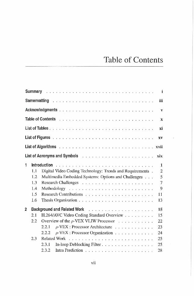
Table of Contents
Summary i
Samenvatting iii
Acknowledgments v
Table of Contents x
List of Tables xi
List of Figures xv
List of Algorithms xvii
List of Acronyms and Symbols xix
1 Introduction 1
1.1 Digital Video Coding Technology: Trends and Requirements . 2
1.2 Multimedia Embedded Systems: Options and Challenges . . . 5
1.3 Research Challenges 7
1.4 Methodology 9
1.5 Research Contributions 11
1.6 Thesis Organization 13
2 Background and Related Work 15
2.1 H.264/AVC Video Coding Standard Overview 15
2.2 Overview of the p-YEX V L I W Processor 22
2.2.1 /9-VEX : Processor Architecture 23
2.2.2 p - V E X : Processor Organizadon 24
2.3 Related Work 25
2.3.1 In-loop Deblocking Filter 25
2.3.2 Intra Predicdon 28
v i i
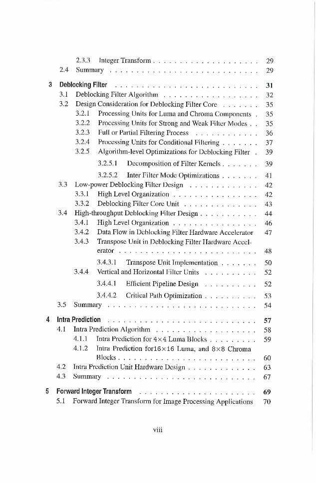
2.3.3 Integer Transform 29
2.4 Summary 29
3 Deblocking Filter 31
3.1 Deblocking Filter Algorithm 32
3.2 Design Consideration for Deblocking Filter Core 35
3.2.1 Processing Units for Luma and Chroma Components . 35
3.2.2 Processing Units for Strong and Weak Filter Modes . . 35
3.2.3 Full or Partial Filtering Process 36
3.2.4 Processing Units for Conditional Fikering 37
3.2.5 Algorithm-level Optimizations for Deblocking Filter . 39
3.2.5.1 Decomposition of Filter Kernels 39
3.2.5.2 Inter Filter Mode Optimizations 41
3.3 Low-power Deblocking Filter Design 42
3.3.1 High Level Organization 42
3.3.2 Deblocking Filter Core Unit 43
3.4 High-throughput Deblocking Filter Design 44
3.4.1 High Level Organization 46
3.4.2 Data Flow in Deblocking Filter Hardware Accelerator 47
3.4.3 Transpose Unit in Deblocking Filter Hardware Accel
erator 48
3.4.3.1 Transpose Unit Implementation 50
3.4.4 Vertical and Horizontal Filter Units 52
3.4.4.1 Efficient Pipeline Design 52
3.4.4.2 Critical Path Optimization 53 3.5 Summary 54
4 Intra Prediction 57
4.1 Intra Prediction Algorithm 58
4.1.1 Intra Prediction for 4 x 4 Luma Blocks 59
4.1.2 Intra Prediction f o r l 6 x l 6 Luma, and 8 x 8 Chroma
Blocks 60
4.2 Intra Prediction Unit Hardware Design 63
4.3 Summary 67
5 Forward Integer Transform 69
5.1 Forward Integer Transform for Image Processing Apphcations 70
v i i i
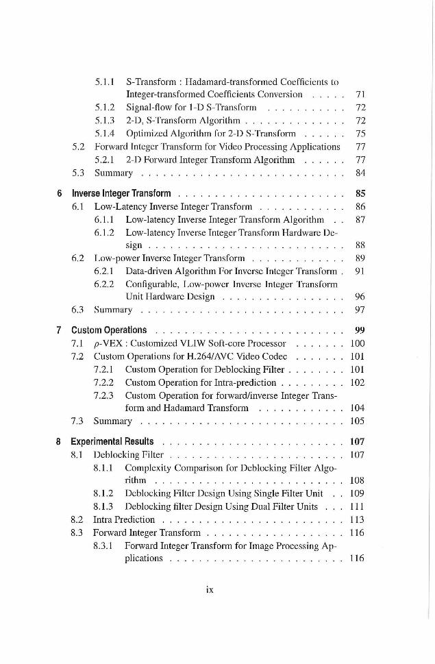
5.1.1 S-Transform : Hadamard-transformed Coefficients to
Integer-transformed Coefficients Conversion 71
5.1.2 Signal-flow for 1-D S-Transform 72
5.1.3 2-D, S-Transform Algorithm 72
5.1.4 Opdmized Algorithm for 2-D S-Transform 75
5.2 Forward Integer Transform for Video Processing Applications 77
5.2.1 2-D Forward Integer Transform Algorithm 77
5.3 Summary 84
6 Inverse Integer Transform 85
6.1 Low-Latency Inverse Integer Transform 86
6.1.1 Low-latency Inverse Integer Transform Algorithm . . 87
6.1.2 Low-latency Inverse Integer Transform Hardware De
sign 88
6.2 Low-power Inverse Integer Transform 89
6.2.1 Data-driven Algori thm For Inverse Integer Transform . 91
6.2.2 Configurable, Low-power Inverse Integer Transform
Unit Hardware Design 96
6.3 Summary 97
7 Custom Operations 99
7.1 p-VEX : Customized VLFW Soft-core Processor 100
7.2 Custom Operadons for H.264/AVC Video Codec 101
7.2.1 Custom Operation for Deblocking Filter 101
7.2.2 Custom Operation for Intra-prediction 102
7.2.3 Custom Operation for forward/inverse Integer Trans
form and Hadamard Transform 104
7.3 Summary 105
8 Experimental Results 107
8.1 Deblocking Filter 107
8.1.1 Complexity Comparison for Deblocking Filter Algo
rithm 108
8.1.2 Deblocking Filter Design Using Single Filter Unit . . 109
8.1.3 Deblocking filter Design Using Dual Filter Units . . . I l l
8.2 Intra Predicdon 113
8.3 Forward Integer Transform 116
8.3.1 Forward Integer Transform for Image Processing Ap
plications 116
ix
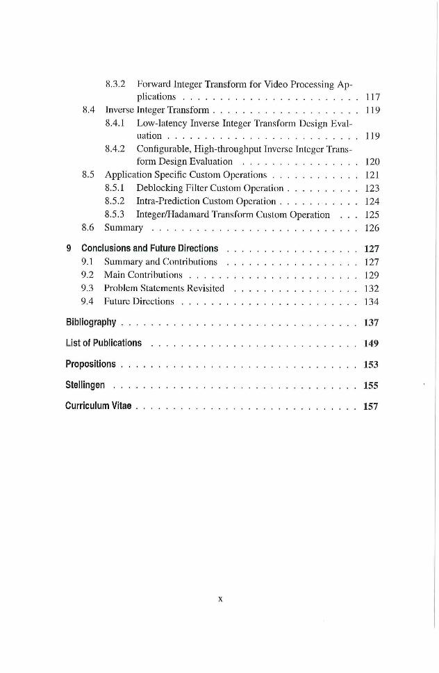
8.3.2 Forward Integer Transform for Video Processing Ap
plications 117
8.4 Inverse Integer Transform 119
8.4.1 Low-latency Inverse Integer Transform Design Eval
uation 119
8.4.2 Configurable, High-throughput Inverse Integer Trans
form Design Evaluation 120
8.5 Application Specific Custom Operations 121
8.5.1 Deblocking Filter Custom Operation 123
8.5.2 Intra-Prediction Custom Operation 124
8.5.3 Integer/Hadamard Transform Custom Operation . . . 125
8.6 Summary 126
9 Conclusions and Future Directions 127
9.1 Summary and Contributions 127
9.2 Main Contributions 129
9.3 Problem Statements Revisited 132
9.4 Future Directions 134
Bibliography 137
List of Publications 149
Propositions 153
Stellingen 155
Curriculum Vitae 157
X
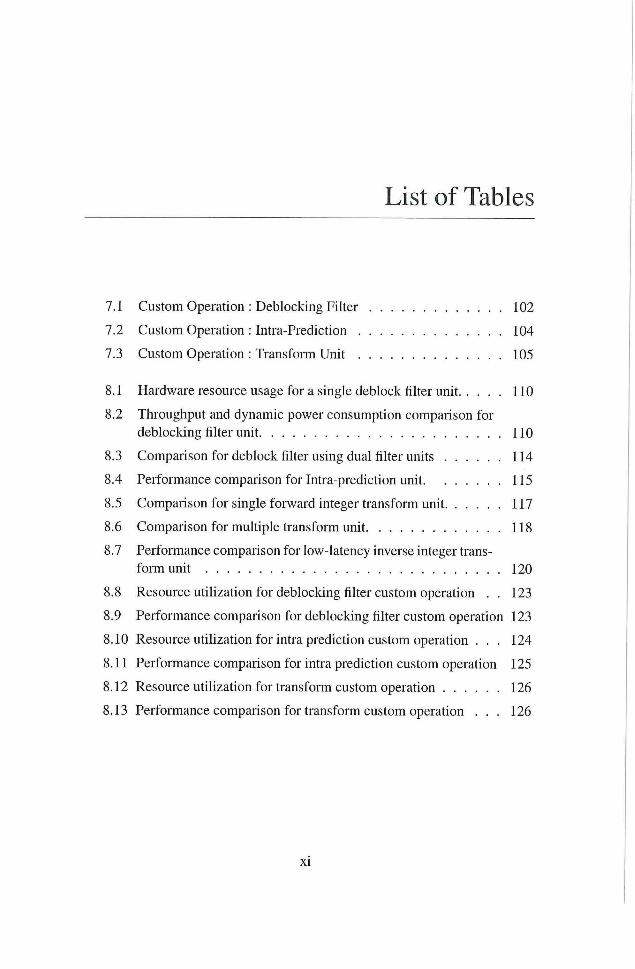
List of Tables
7.1 Custom Operation : Deblocking Filter 102
7.2 Custom Operation : Intra-Prediction 104
7.3 Custom Operation : Transform Unit 105
8.1 Hardware resource usage for a single deblock filter unit 110
8.2 Throughput and dynamic power consumpdon comparison for
deblocking filter unit 110
8.3 Comparison for deblock filter using dual filter units 114
8.4 Performance comparison for Intra-prediction unit 115
8.5 Comparison for single forward integer transform unit 117
8.6 Comparison for multiple transform unit 118
8.7 Performance comparison for low-latency inverse integer trans
form unit 120
8.8 Resource utilization for deblocking filter custom operadon . . 123
8.9 Performance comparison for deblocking filter custom operation 123
8.10 Resource utilizadon for intra predicdon custom operadon . . . 124
8.11 Performance comparison for intra predicdon custom operation 125
8.12 Resource utihzadon for transform custom operation 126
8.13 Performance comparison for transform custom operation . . . 126
xi

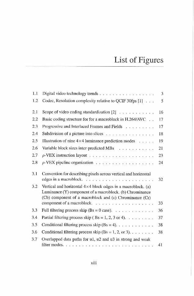
List of Figures
1.1 Digital video technology trends 3
1.2 Codec, Resolution complexity relative to QCIF30fps [1] . . . 5
2.1 Scope of video coding standardizadon [2] 16
2.2 Basic coding structure for for a macroblock in H.264/AVC . . 17
2.3 Progressive and Interlaced Frames and Fields 17
2.4 Subdivision of a picture into slices 18
2.5 Illustradon of nine 4 x 4 luminance prediction modes 19
2.6 Variable block sizes inter-predicted MBs 21
2.7 p - V E X instruction layout 23
2.8 p - V E X pipeline organization 24
3.1 Convention for describing pixels across vertical and horizontal
edges in a macroblock 32
3.2 Vertical and horizontal 4 x 4 block edges in a macroblock. (a)
Luminance (Y) component of a macroblock. (b) Chrominance
(Cb) component of a macroblock and (c) Chrominance (Cr)
component of a macroblock 33
3.3 Full filtering process skip (Bs = 0 case) 36
3.4 Partial filtering process skip ( Bs = 1, 2, 3 or 4) 37
3.5 Conditional filtering process skip (Bs = 4) 38
3.6 Conditional filtering process skip (Bs = 1, 2, or 3) 38
3.7 Overlapped data paths for u l , u2 and u3 in strong and weak
filter modes 41
x i i i
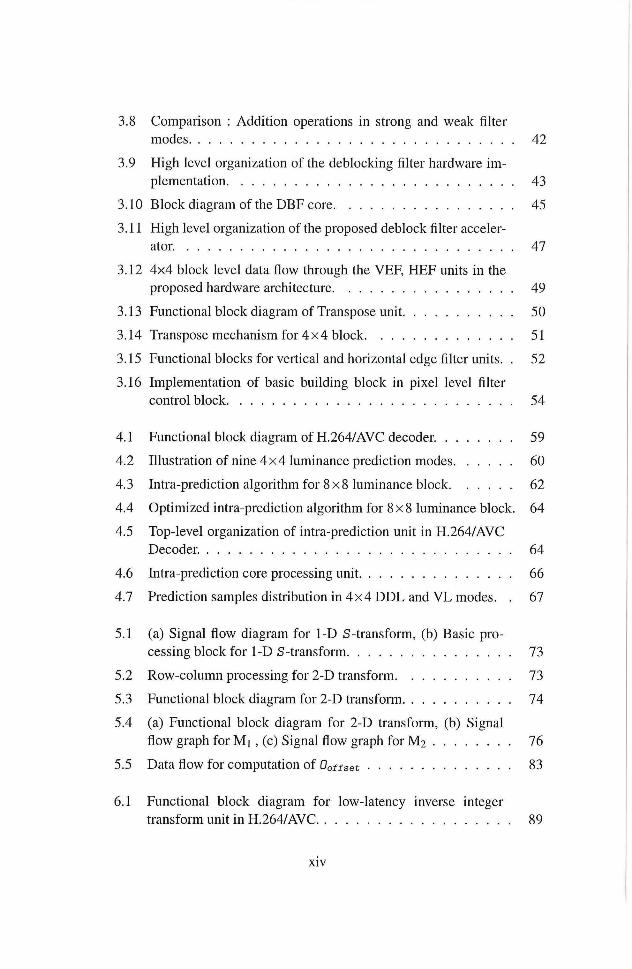
3.8 Comparison : Addition operations in strong and weak filter
modes 42
3.9 High level organization of the deblocking filter hardware im
plementation 43
3.10 Block diagram of the DBF core 45
3.11 High level organizadon of the proposed deblock fiher acceler
ator 47
3.12 4x4 block level data flow through the VEF, HEF units in the
proposed hardware architecture 49
3.13 Functional block diagram of Transpose unit 50
3.14 Transpose mechanism for 4 x 4 block 51
3.15 Functional blocks for vertical and horizontal edge filter units. . 52
3.16 Implementation of basic building block in pixel level filter
control block 54
4.1 Functional block diagram of H.264/AVC decoder. 59
4.2 Illustration of nine 4 x 4 luminance prediction modes 60
4.3 Intra-prediction algorithm for 8 x 8 luminance block 62
4.4 Optimized intra-prediction algorithm for 8 x 8 luminance block. 64
4.5 Top-level organization of intra-prediction unit in H.264/AVC
Decoder. 64
4.6 Intra-prediction core processing unit 66
4.7 Prediction samples distribution in 4 x 4 D D L and V L modes. . 67
5.1 (a) Signal flow diagram for 1-D S-transform, (b) Basic pro
cessing block for 1 -D S-transform 73
5.2 Row-column processing for 2-D transform 73
5.3 Functional block diagram for 2-D transform 74
5.4 (a) Functional block diagram for 2-D transform, (b) Signal
flow graph for M i , (c) Signal flow graph for M 2 76
5.5 Data flow for computation of Ootfset 83
6.1 Functional block diagram for low-latency inverse integer
transform unit i n H . 264/AVC 89
xiv
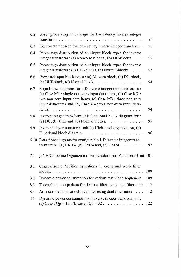
6.2 Basic processing unit design for low-latency inverse integer
transform 90
6.3 Control unit design for low-latency inverse integer transform. . 90
6.4 Percentage distribution of 4x4input block types for inverse
integer transform : (a) Non-zero blocks , (b) DC-blocks. . . . 92
6.5 Percentage distribution of 4x4input block types for inverse
integer transform : (a) ULT-blocks, (b) Normal-blocks 93
6.6 Proposed input block types : (a) All-zero block, (b) DC-block,
(c) ULT-block, (d) Normal block 94
6.7 Signal-flow diagrams for 1-D inverse integer transform cases :
(a) Case M l : single non-zero input data-item , (b) Case M 2 :
two non-zero input data-items, (c) Case M3 : three non-zero
input data-items and, (d) Case M 4 : four non-zero input data-
items 94
6.8 Inverse integer transform unit funcdonal block diagram for :
(a) DC, (b) ULT and, (c) Normal blocks 95
6.9 Inverse integer transform unit (a) High-level organization, (b)
Functional block diagram 96
6.10 Data-flow diagrams for configurable 1-D inverse integer trans
form units : (a) CM14, (b) CM24 and, (c) CM34 97
7.1 p - V E X Pipeline Organizadon with Customized Functional Unit 101
8.1 Comparison : Addidon operations in strong and weak filter
modes 108
8.2 Dynamic power consumption for various test video sequences. 109
8.3 Throughput comparison for deblock filter using dual filter units 112
8.4 Area comparison for deblock filter using dual filter units . . . 112
8.5 Dynamic power consumpdon of inverse integer transform unit
(a) Case : Qp - 16 , (b)Case : Qp = 32 122
X V


List of Algorithms
3.1 : Deblocking filter algorithm for single block edge 34
3.2 : Optimized deblocking filter algorithm for single block edge. . 40
4.1 : Proposed decomposed filter kernels for intra-prediction modes. 61
xv i i

List of Acronyms and Symbols
ALU Arithmetic Logic Unit
ASIC Application Specific Integrated Circuit
ASIP Application Specific Instruction-set Processor
BRAM Block R A M
CAB AC Context Adaptive Binary Arithmetic Coding
CAVLC Context Adaptive Variable Length Coding
CFU Custom Functional Unit
CIF Common Intermediate Format
OCT Discrete Cosine Transform
DPR Data Processing Rate
DSC Digital Still Cammera
DSP Digital Signal Processor
FIR Finite Impulse Response filter
FPGA Field Programmable Gate AiTays
GPP General Purpose Processor
HDTV High Definition T V
ILP Instruction Level Parallelism
ISA Instraction Set Architecture
JPEG Joint Picture Expert Group
JVT Joint Video Team
MPEG Motion Picture Expert Group
RC Reconfigurable Computing
RISC Reduced Instruction Set Computer
RTL Register Transfer Logic
SAD Sum of Absolute Difference
SAID Sum of Absolute Transformed Difference
VCD Value Change Dump
VCL Video Coding Layer
VEX V L I W Example
VHDL Very High Scale Integrated Circuits Hardware Description Language
VLIW Very Long Instruction Word
xix

Introduction
DI G I T A L video coding is one of the primidve apphcations of multimedia
embedded systems. With the evoludon of context-aware processing in
advanced video coding standards, the exploitadon of parallehsm is becoming
increasingly challenging [3] [4]. Advanced video codecs may consume a sig
nificant amount of processing time and energy/power, due to their adaptive
nature of processing, to provide better compression. Beside performance and
power consumpdon, other parameters like cost, short-dme-to-market, mass
volume production, flexibihty and re-useability have created a multidimen
sional pressure on industry, as well as on research to come up with innovative
architectures for embedded multimedia systems. The realization of advanced
video coding with high-resolution videos on battery-powered mobile devices
demands high complexity reduction in video coding algorithms for their real
time and low-power implementation. Consequently, the main objectives of this
dissertation are to investigate how to achieve high-performance for real-time
video processing applications in terms of throughput, while utihzing less on-
chip resources. Similarly, this dissertation also proposes adaptive, low-power
hardware design for multimedia video compression apphcations on battery-
powered electronic devices without compromising the video quality.
This introductory chapter starts with providing a brief overview on cuiTent
trends in digital video processing apphcations/services and state-of-the-art in
video compression technologies (Section 1.1). The hardware design options
and trends in state-of-the-art for implementation of multimedia embedded sys
tems along with the associated issues and challenges are summarized in Sec
tion 1.2. The summary of research challenges and goals is provided in Sec
tion 1.3. Similarly, Sections 1.4 and 1.5 describe the methodology and thesis
contributions respectively. Finally, Section 1.6 presents organization of this
dissertation.
1
2 C H A P T E R 1. I N T R O D U C T I O N
1.1 Digital Video Coding Technology: Trends and Requirements
Why Video Compression? A video CODEC (enCOder / DECoder pair) is
a software component or hardware device that enables compression and de
compression of digital video signal. Typically, videos must be encoded before
their storage or transmission, and decoded before their display. The amount
of uncompressed video data is too large for limited transmission bandwidth or
storage capacities. For example, to store a 2 - hours uncompressed video of
fuh High Definidon (HD) resoludon frames (1920 x 1080 pixels), a capacity
of 2 (hours) x60 (minutes per hour) x 6 0 (seconds per minute) x25(frame
rate, frames per second) x 1920 x 1080 (frame size in pixels) x 3 / 2 (number
of bytes per pixel) = 559, 872 GB is required, which far exceeds the capacity
of current opdcal disc storage (50 GB for dual layer Blue-ray Disc). With
efficient compression techniques, a significant reduction in amount of video
data can be achieved with httle or no adverse effect on the visual quahty.
Digital Video Services/Trends: Digital video coding is an enabhng technol
ogy and generating ever new applications with a broadening range of require
ments regarding basic video characteristics, such as spatio-temporal resolu
tion, chroma format, and sample accuracy. Digital video-based services have
become an integral part of wide range of industries-from telecommunications
to broadcasting and entertainment to consumer electronics. Today, the appli
cation areas for digital video coding technology range f rom videoconferenc
ing over mobile T V and broadcasting of standard-/ high-definition T V con
tent, up to very high-quality applications such as professional digital video
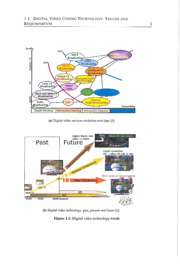
recording or digital cinema/large-screen digital imagery as illustrated in Fig
ure 1.1a. Recently, the demands for more realistic multimedia contents have
been increased dramatically. The ultimate objective of future video process
ing technology is to offer reahstic 3D visual experiences. Full high-definition
television technology has been adopted in consumer electronics, but it cannot
offer sufficient realism yet. Therefore, attempts are being made to not only
provide even higher-resolution images in spatial dimension (HD to Ultra HD) ,
but also higher frame-rates up to 200 Hz (temporal dimension) and realistic
3D perception with more views (Figure L i b ) [5],
Similarly, recent advances in computing and the communication technology
have led to a significantly increased use of a large number of multimedia com
puting devices hke mobile phones, personal navigation devices (PND), per
sonal multimedia players (PMP), mobile internet devices (MID) , tablets and
1.1. D I G I T A L V I D E O C O D I N G T E C H N O L O G Y : T R E N D S A N D
R E Q U I R E M E N T S 3
(a) Digital video services evolution over time [5]
(b) Digital video technology: past, present and future [5]
Figure 1.1: Digital video technology trends
4 C H A P T E R 1. I N T R O D U C T I O N
notebooks. The average smart-phone usage grew 81% in 2012, whereas the
mobile video traffic was more than 51°/. of the total global mobile data traf
fic by the end of same year [6]. The convergence of mobile phone, internet,
mapping, gaming, and office automadon tools with high-quality video and sdll
imaging capture capability are becoming a strong market trend for portable
devices. High-density video encode and decode, 3D graphics for gaming,
increased apphcadon-software complexity, and uhra-high-bandwidth 4G mo
dem technologies are driving the CPU performance and memory bandwidth
requirements close to the PC segment. Consequently, on the one hand, the next
generation multimedia apphcations being executed on these portable multime
dia devices are becoming increasingly complex and consume more power to
f u l f i l l the end-user requirements. On the other hand, the growth in recharge
able battery-capacity has shown modest increases. Thus, the larger demand
for increased functionahty and speed has increased the severity of the power
constraint in the world of hand-held and mobile multimedia systems. Even in
the case of applications that have an unhmited energy source, we have moved
into an era of power-constrained performance since heat removal requires the
processor to operate at lower clock rates than dictated by the logic delays.
Standard Based Video Coding: Different compression technologies, both
proprietary and industry standards, are available. Video codec standards are
important in ensuring compatibility and interoperability. Over the last two
decades, standard based digital video coding/compression technologies have
evolved f r o m MPEG-1 to MPEG-2/H.262 to H.264/AVC. The H.264/AVC [7]
is the latest video coding standard joint iy developed by ISO-IEC and ITU-T.
I t provides 2 x compression compared to previous coding standards (such as
H.262/MPEG-2, H.263) for the same subjective video quality at the cost of
additional computational complexity and energy consumption (approx. 10 x
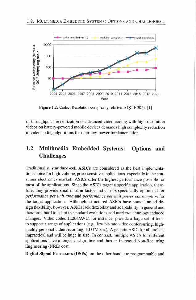
relative to MPEG-4 advance simple profile [8]). Beside higher resolutions,
the key reason of increasing video coding complexity is the complex tool-set
for advance video encoders. The authors in [1] state an expected increase
in the video complexity by 2x every two years (Figurei.2). Although, high
resolutions are mainly targeted for high-end multimedia devices, multiview
video conferencing or personal recording at much higher resolutions Quad-
H D , 3840 X 2160 or 4096 x 2304) is foreseen within next few years on mobile
devices. Industrial prototypes like [9] have akeady demonstrated the feasibility
of 3D-videos and multiview video coding on mobile devices using two views.
In short, as mentioned before, with the evolution of context-aware processing
in advanced video coding standards, exploitation of parallehsm is becoming
extensively challenging [3], [4]. Moreover, besides high performance in terms
1.2. M U L T I M E D I A E M B E D D E D S Y S T E M S : O P T I O N S A N D C H A L L E N G E S 5
coduc CJ:jn^;ilu?(ily (x10) ruyuJulion c ó n ' p l u x i l / ^ ^ ^ o v o r i i l l uunip lo i i ly
2004 2005 2006 2007 2008 2009 2010 2011 2013 2015 2017 2020
Year
Figure 1.2: Codec, Resolution complexity relative to QCIF 30fps [1]
of throughput, the realization of advanced video coding with high resolution
videos on battery-powered mobile devices demands high complexity reduction
in video coding algorithms for their low-power implementation.
1.2 Multimedia Embedded Systems: Options and Challenges
Traditionally, standard-cell A S I C s are considered as the best implementa
tion choice for high-volume, piice-sensitive applications-especially in the con
sumer electronics market. ASICs offer the highest performance possible for
most of the applications. Since the ASICs target a specific applicadon, there
fore, they provide smaher form-factor and can be specificahy opdmized for
performance per unit area and performance per unit power consumption for
the target apphcation. Although, structured ASICs have some limited de
sign flexibility, however, ASICs lack flexibihty and adaptability in general and
therefore, hard to adapt to standard evolutions and market/technology induced
changes. Video codec H.264/AVC, for instance, provide a large set of tools
to support a range of applications (e.g., low bit-rate video conferencing, high-
quality personal video recording, HDTV, etc.). A generic ASIC for all tools is
impractical and w i l l be huge in size. In contrast, multiple ASICs for different
apphcations have a longer design time and thus an increased Non-Recuning
Engineering (NRE) cost.
Digital Signal Processors (DSPs), on the other hand, are programmable and
6 C H A P T E R 1. I N T R O D U C T I O N
offer high flexibihty over ASICs. DSPs include support for frequently used
signal processing operadons and addressing modes. These operations include
multiple parallel muldply-accumulate operations used to implement efficiendy
computation kernels, such as FIR/IIR filters and linear transformation opera
tions. The speciahzed ISA and specialized functional units, therefore, enable
DSPs to provide better performance per unit area and performance per unit
power consumption over General Puipose Processor (GPPs) for a software-
based muldmedia system. However, DSPs alone may not satisfy the power
and/or performance challenges when considering the combination of tight
power budgets on battery-powered mobile devices and intricate processing na
ture of next-generation multimedia algorithms. Moreover, DSP petformance is
limited by the avaflable data bandwidth f rom the external memory [10], [11].
Although stream architecture [10] provides an efficient memory hierarchy to
exploit the concurrency and data locality, i t exploits a hmited amount of par
allehsm (e.g., only data level paraUelism) [12]. DSP based software solutions
alone do offer flexibility but can not provide the required performance and,
therefore, dedicated hardware accelerators are often inevitable.
ASIPs can be tailored for a specific application and, therefore, provides a
tradeoff between flexibility and performance of some degree. They overcome
the shortcomings of DSPs and ASICs and provide better performance per unit
area and peiformance per unit power, when compared with GPP and DSPs.
A number of IPs for embedded customizable processor along with tool suites
are available from vendors like Tensilica and ARC. Application specific in
struction set processors (ASIPs) offers a compromise between flexibility and
performance, however, the customization of ASIP for larger apphcations with
many kernels may end up with considerably larger core size and, therefore,
requires larger silicon footprint.
MPSoCs, on the other hand, deliver high performance and programmability
by integrating applicadon-specific hardware accelerators with programmable
processors hke GPPs and DSPs. Commercially available O M A P f rom Texas
Instruments, Trimedia/Nexperia f rom Philips/NXP and Nomadik by STMi-
croelectronics are some prominent examples of MPSoCs. Since the pro
grammable cores and apphcation-specific hardware accelerators are selected
at design time targeting certain type of applications. Therefore, MPSoC may
not provide sufficient performance for applications f rom different domains.
Moreover, the currently-used MPSoC may becomes obsolete because of need
to support a new standard or evolutions in the current standard..
Reconfigurable Computing (RC) is emerging as the new paradigm for sat-
1.3. R E S E A R C H C H A L L E N G E S 7
isfying the simultaneous demand for application performance and flexibility.
Reconfigurable computing udlizes hardware that can be adapted at run-dme to
facilitate greater flexibihty without compromising performance. It combines
the flexibility of software with the high performance of hardware by process
ing with very flexible high speed computing fabrics like FPGAs. The principal
difference when compared to using ordinary microprocessors is the abihty to
make substandal changes to the data-path itself in addition to the control flow.
On the other hand, the main difference with custom hardware (ASICs) is the
possibihty to adapt the hardware during run-dme by loading a new circuit
on the reconfigurable fabric. Reconfigurable architectures can exploit fine-
grain and coarse-grain parallelism available in the application because of the
adaptability. Exploiting this paraflehsm provides significant performance ad
vantages compared to conventional microprocessors. The re-configurability
permits adaptation of the hardware for specific computadons in each apphca-
don to achieve higher performance compared to software. Complex funcdons
can be mapped onto the architecture achieving higher silicon utilization and
reducing the instruction fetch and execute bottleneck.
1.3 Research Challenges
In previous secdons, we argued that even though processor speeds and net
work bandwidth continue to increase, efficient video processing for muldme
dia consumer electronics devices is still a very important requirement for a
successful/competidve product. Consequently, in this dissertadon we shall in-
vesdgate:
• How to achieve high-performance and flexible processing in video pro
cessing/compression applications 7
Since H.264/AVC is state-of-the-art in video compression standards and has
already been widely accepted by the industry. Consequently, we shall fo
cus on how to improve the performance of compute-intensive modules in
H.264/AVC video codec in terms of throughput, resources/area-cost and
power-consumpdon. Our first problem statement is:
• How to reduce the coding complexity and improve the real-time perfor
mance without compromising the video quality ?
Like previous video coding standards (H.261, H.262/MPEG-2, H.263 etc.),
H.264/AVC also does not exphcitly define a CODEC (enCOder / DECoder
8 C H A P T E R 1 . I N T R O D U C T I O N
pair). Rather, it defines the syntax of an encoded video bitstream together with
methods for the decoding process of these syntax elements. There are a couple
of syntax elements, where a set of constraints is imposed by the video coding
standard and the actual method/algorithm to compute these syntax elements is
out of scope of the standard. Whereas, for couple of other compute-intensive
syntax elements, an algorithm/method along with constraints is specified in
the H.264/AVC video coding standard. This dissertation shall focus on the
complexity reduction of standardized video coding algorithms/methods.
The tradeoff of various types of architectures to implement DSP algorithms
has been a topic of research since the initial development of the theory. Re
cently, the application of these DSP algorithms to systems those require low
cost and the lowest possible energy consumption has placed a new emphasis
on defining the most appropriate solutions. Moreover, the flexibility require
ment to adapt to standard evolutions and market/technology induced changes
has become a new dimension in the algorithm/architecture design. Traditional
Von Neumann architecture-based approach, provides flexibility through soft
ware programming. This approach was based on technology assumptions that
hardware was expensive and the power consumption was not critical. There
fore, time multiplexing approach was used to provide maximum sharing of the
hardware resources. The situation, however, is fundamentally different now.
The energy/power consumption is a critical design constraint beside through
put in battery-powered portable devices. Whereas, wi th potentially thousands
of multipliers and adders available on a chip, hardware is rather a cheap com
modity. Similarly, even in the case of applications with an unlimited energy
source, we have moved into an era of power-constrained performance since
heat removal requires the processor to operate at lower clock rates than dic
tated by the logic delays. Consequently, in reladon with above mentioned first
problem statement, this dissertation shall:
• Propose new algorithms or optimizations for existing algorithms within
the scope of standardized video coding blocks/components (H.264/AVC)
to achieve complexity reduction without compromising the video qualit}'.
• Design, implementation, and evaluation of high-throughput, area-
efficient and low-power video signal processing architecture for various
video processing components/tools in H.264/AVC.
As mentioned before, the flexibility requireinent to adapt to video coding stan
dard evolutions and market/technology induced changes has become a new di
mension in the algorithm/architecture design. We believe that reconfigurable
1.4. M E T H O D O L O G Y 9
computing could possibly be the solution to provide the needed flexibility be
side performance. Our second problem statement is:
• How can reconfigurable computing be utilized to improve the flexibility
and peiformance for video coding signal processing applications?
Reconfigurable computing has proven itself to be able to speed-up many ap
plications despite its lack in achieving high frequencies. However, frequency
is not the sole factor that determines performance. Field-programmable Gate
Arrays (FPGAs) - as the most udhzed reconfigurable fabric nowadays - pro
vide a large amount of parallel structures that when exploited efficiently can
greatly contribute to the speedup of applications.
Digital video coding/signal processing applicadons have been identified to
have significant fine- and coarse-grained parallelism [13] Therefore, Very
Long Instrucdon Word ( V L I W ) processors can be utilized to increase the per
formance beyond normal Reduced Instrucdon Set Computer (RISC) architec
tures [14]. While RISC architectures only take advantage of temporal paral
lelism (by utihzing pipelining), V L I W architectures can addidonally take ad
vantage of the spadal paraflehsm by udlizing muldple fimctional units (FUs)
to execute several operations simultaneously. V L I W processor improves the
perfonnance by exploiting Instracdon Level Parallehsm (ILP) in a program.
Similarly, the customization of processors for an application is another way of
improving the peiformance for a moderate cost. Consequently, in relation with
our second problem statement, this dissertation shall:
• Propose customization of reconfigurable VLIW processor for compute-
intensive H.264/AVC video codec tools to improve the performance.
1.4 Methodology
From digital video coding perspective, with a wide range of target apphcations
f rom low-end to high-end under various constraints, such as throughput, power
consumpdon and resources/area cost, an application-specific implementadon
for digital video coding algorithms, may be pure software, pure hardwired, or
something in between. The video coding algorithm defines a detailed imple
mentation outhne of a required original function and, therefore, determines
how to solve the problem and how to reduce the original complexity. In order
to do an optimal implementation, it is essendal to fu l ly understand the princi
ples behind and algorithms employed in video coding as it is a key to reduce
10 C H A P T E R 1. I N T R O D U C T I O N
power consumption and improve efficiency. In this secdon, we propose differ
ent steps to achieve high-performance video processing systems as proposed
in the previous section. These steps are hsted in the following:
• Identify the compute-intensive video compression tools within the scope
of video coding standard H.264/AVC.
• Propose algorithmic optimization to reduce complexity ofthe video com
pression algorithms.
• Exploit video signal statistics and data correlations for further complex
ity reduction.
• Propose efficient design in terms of high-throughput, low-area and
low-power consumption, for compute-intensive processing units in
H.264/AVC.
• Investigate the processing chain for video compression engine in
H.264/AVC for possible complexity reduction by reusing the interme
diate results and propose an efficient algorithm.
• While titiUzing the reduced-complexity optimized algorithms, design,
implement and evaluate the high-throughput, area-efficient and low-
power solution for compute-intensive processing units in H.264/AVC.
• Validate the proposed design using variety of video test sequences from
Joint Video Team (JVT), responsible for development of video coding
standard H.264/AVC, and ffirther comparing the results against that of
reference video coding standard implementation provided by JVT.
In order to support processor level adaptivity and customization, dynamically
reconfigurable processor (/?-VEX) shall be used as a target computing plat
form. /9-VEX is an open source, extensible and reconfigurable soft-core V L f W
processor. The processor architecture is based on the V E X ( V L f W Example)
Instrucdon Set Architecture (ISA), as introduced in [15], and is implemented
on an FPGA. The ISA of p - V E X shall be extended with custom operations.
From the prospective of our second problem statement, we propose to combine
multiple-issue architectures (p -VEX) and customization techniques to further
improve the performance of the processor.
• Design, implement, and evaluate custom operations for compute-
intensive processing tools/units within scope of video coding standard
H.264/AVC.
1.5. R E S E A R C H C O N T R I B U T I O N S 11
1.5 Research Contributions
The research earned out in the course of this PhD project is published in several
scientific publicadons. This secdon highlights the main contribudons of the
research work described in this dissertation, as follows:
1. Indoop deblocking filter.
• The complexity of indoop deblocking filter algorithm is reduced
by novel decomposition of filter kernels and intra-module opti
mizations. The complexity of the deblocking filter algorithm is
reduced by more than 51°/, when compared with that of algorithm
described in the video coding standard H . 2 6 4 / A V C [ 1 6 ] .
• A low-power hardware design for deblocking fiher unit is pro
posed. Experimental results suggest that the dynamic power con
sumption is reduced up to 50°/ , when compared with state-of-the-
art designs in hterature. [ 1 7 ] .
• For real-time video processing applications, a high-throughput,
area-efficient hardware design, based on the low-power filter unit,
is proposed. . This design utihzes 2 filter units and, therefore,
can process input pixels on-the-fly in both horizontal and verti
cal directions. The proposed design provides significandy higher
throughput (more than 63° / when compared with state-of-the-art
in literature having similar area-cost) and require less on-chip area
(around 35° / when compared with state-of-the-art in hterature hav
ing similar throughput) [ 1 6 ] .
2 . Intra-prediction
• The complexity of intra-prediction algorithm for various intra-
prediction modes is reduced by 27° / - 60° / in comparison with intra-
prediction algorithm proposed in H . 2 6 4 / A V C video coding stan
dard. A configurable, high-throughput, and area-efficient hardware
design for intra-prediction unit, based on the reduced complexity
intra-prediction algorithm, is proposed in this dissertation. The
comparison with other state-of-the-art suggests that our proposed
hardware design provides 50° / -75° / performance improvement and
requires only 2 I K gates for its implementation, when synthesized
under 0 . 1 8 / im C M O S standard cell technology [ 1 8 ] .
12 C H A P T E R 1. I N T R O D U C T I O N
3. Forward integer transform
• A transformation, to compute integer-transformed residual block
f rom Hadamard-transformed residual block in the processing chain
of H.264/AVC video codec, is proposed in this dissertadon. This
approach reduces the number of addition operations by more than
507, for realization of integer transform in the video codec. The
comparison with the existing single 4 x 4 forward integer transform
solutions f rom the literature suggest that the proposed solution pro
vides the minimum latency penalty (4.82ns) among all solutions
and also requires significantly less area (2 . 6K gates) in terms of
equivalent gate count for its hardware implementation. Therefore,
it provides up to 5 times better performance in terms of through
put/area rado for the same process technology. [19].
• Similarly, a low-latency and area-efficient solution for reahzation
of forward integer transform unit in the intra-frame processing
chain is proposed. With this proposed soludon, the effective la
tency penalty for the forward integer transform unit is reduced to
zero. In additions to zero latency penalty in the intra-frame pro
cessing chain, the proposed soludon provides up to 30 dmes better
performance in terms of throughput/area ratio. [19].
4. Inverse integer transform
• For inverse integer transform unit, a configurable, low-power hard
ware design is presented in this dissertadon. The proposed design
is based on a data-driven computation algoiithm for the inverse in
teger transform. I t efficiently exploits the zero-valued coefficients
in the input blocks to reduce dynamic power consumption. The ex
perimental results show that the proposed design consumes signif
icantly less dynamic power (up to 80°/, reduction), when compared
with existing conventional designs for the inverse integer trans
form, with a small area-overhead (approximately 2 K gates) [20]
[21].
5. Custom instructions/processing units for extensible, reconfigurable,
soft-core V L I W processor (p -VEX) .
• In this dissertadon, we also proposed custom operadons for de
blocking filter, intra-prediction and forward/inverse integer trans
fo rm units in H.264/AVC foe a reconfigurable V L I W processor.
1.6. T H E S I S O R G A N I Z A T I O N 13
The datapath is based on the optimized algorithms presented in
this dissertadon. The proposed custom operations significandy re
duce the compute time (approximately 40% - 59°/. ) for the corre
sponding compute-intensive functions in fI .264/AVC on a recon
figurable, soft-core V L I W processor (p -VEX) . [8.9, 8.11, 8.13].
1.6 Thesis Organization
The remainder of the thesis is organized as follows.
Chapter 2 provides the background for digital video coding, with a focus on
advanced video codec H.264/AVC. Next, the prominent related work on high-
throughput, area-efficient and low-power codec design and implementations is
presented. The background for dynamically reconfigurable V L I W processor
(p -VEX) is also is presented towards end of the chapter.
Chapter 3 covers the deblocking filter in H.264/AVC. Low-power and high-
throughput hardware designs based on single and double filter units are pre
sented for image and real-time video processing apphcations, respectively.
Chapter 4 deals with the intra-prediction module in H.264/AVC. This chapter
introduces an optimized algorithm to compute all intra-prediction mode for
4x4 pixel block along with the hardware design.
Chapter 5 introduces two designs for the reahzation of forward integer trans
form. A novel transform is also presented in this chapter to derive the forward
integer transform coefficients directly f rom that of Hadamard transfoim coef
ficients.
Chapter 6 deals with inverse integer transfoim module in H.264/AVC. Two
hardware designs for the inverse integer transform are presented in this chap
ter. The first design is intended for intra-frame encoder with reduced latency.
The proposed design process the input data on-the-fly to produce the inverse
transformed data block. A data-driven algorithm with variable number of oper
ations is also introduced in this chapter. The second hardware design, based on
the data-driven algorithm, provides high-throughput and consume significantly
less dynamic power for its implementation.
Chapter 7, proposes to incorporate a customized functional unit in the data
path of reconfigurable, soft-core, V L I W processor (p -VEX) . This customized
functional unit implements several application specific custom instructions for
the compute intensive processing blocks in video codec H.264/AVC.

14 C H A P T E R 1 . I N T R O D U C T I O N
Chapter 8 provides experimental results for the proposed designs, in terms of
throughput, area and dynamic power consumption. A comparison with the
designs already presented in the hterature is also done in the same chapter
Finahy, Chapter 9 concludes our work and also provides outlook of the poten
tial future works.
Background and Related Work
IDEO compression or video encoding is a process of reducing the amount V of data required to represent a digital video signal, prior to transmission
or storage. Similarly, video decoding recovers the digital video signal f rom
the compressed representation, prior to display. In order to provide solutions
of high quality (high frame resolution, high frame rate, and low distortion) or
low cost (low bit rate for storage or transmission) or both, video compression is
indispensable when storage capacity or transmission bandwidth is constrained.
Advancement in semiconductor technology makes possible the efficient imple
mentation of effective but computationahy comphcated compression methods.
This chapter provides the background information for the H.264/AVC video
coding standard and introduces the funcdonal blocks of video codec in Sec
tion 2.1. This section also identifies the compute-intensive functional units in
H.264/AVC video codec. Section 2.2 introduces the p - V E X Reconfigurable
V L f W processor. Einally, Section 2.3 presents the related work for the identi
fied compute-intensive video coding functional units in H.264/AVC and Sec
tion 2.4 summarizes this chapter.
2.1 H.264/AVC Video Coding Standard Overview^
The H.264/AVC (also known as MPEG4 Part 10) is state-of-the-art video cod
ing standard joint ly developed by ITU-T and ISO/IEC. In common with earlier
video coding standards f rom ITU-T (such as H.261 and H.263) and ISO/IEC
(such as MPEG-1, MPEG-2, and MPEG-4), the H.264/AVC standard does not
exphcitly define a CODEC (enCOder / DECoder pair). Rather, the standard
defines the syntax of an encoded video bit-stream together with the method of
'The overview of the H.264/AVC video coding standard is extracted from [2] and [7].
15
16 C H A P T E R 2 . B A C K G R O U N D A N D R E L A T E D W O R K
S o u r c e Pre - P r o c e s s i n g E n c o d i n g Pre - P r o c e s s i n g E n c o d i n g
Pos t - P r o c e s s i n g
& n r r i i r R e c o v e r y
, 1 D e c o t l i n g
D e s l i n a t i o n Pos t - P r o c e s s i n g
& n r r i i r R e c o v e r y 1 D e c o t l i n g Pos t - P r o c e s s i n g
& n r r i i r R e c o v e r y 1 Sco|)e o l ' .S lnnda r i l 1
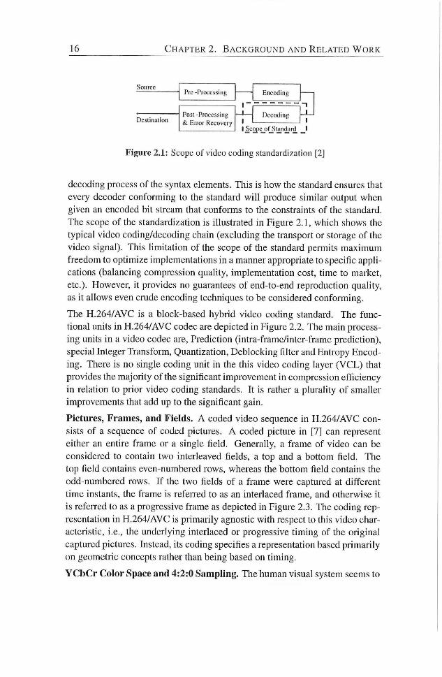
Figure 2.1: Scope of video coding standardization [2]
decoding process of the syntax elements. This is how the standard ensures that
every decoder conforming to the standard w i h produce similar output when
given an encoded bit stream that conforms to the constraints of the standard.
The scope of the standardization is illustrated in Figure 2 . 1 , which shows the
typical video coding/decoding chain (excluding the transport or storage of the
video signal). This hmitadon of the scope of the standard permits maximum
freedom to optimize implementadons in a manner appropriate to specific appli
cations (balancing compression quality, implementation cost, dme to market,
etc.). However, it provides no guarantees of end-to-end reproduction quahty,
as it allows even crude encoding techniques to be considered conforming.
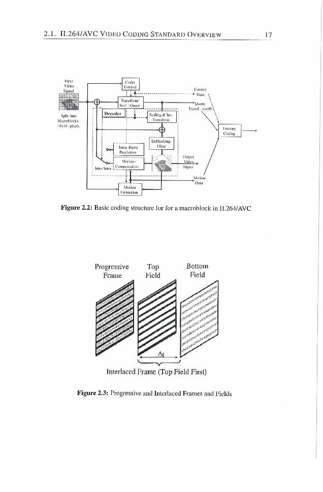
The H . 2 6 4 / A V C is a block-based hybrid video coding standard. The func
donal units in H . 2 6 4 / A V C codec are depicted in Figure 2 .2 . The main process
ing units in a video codec are. Prediction (intra-frame/inter-frame predicdon),
special Integer Transform, Quandzation, Deblocking filter and Entropy Encod
ing. There is no single coding unit in the this video coding layer ( V C L ) that
provides the majority of the significant improvement in compression efficiency
in relation to prior video coding standards. It is rather a plurality of smaller
improvements that add up to the significant gain.
Pictures, Frames, and Fields. A coded video sequence in H . 2 6 4 / A V C con
sists of a sequence of coded pictures. A coded picture in [ 7 ] can represent
either an endre frame or a single field. Generally, a frame of video can be
considered to contain two interleaved fields, a top and a bottom field. The
top field contains even-numbered rows, whereas the bottom field contains the
odd-nuinbered rows. I f the two fields of a frame were captured at different
time instants, the frame is referred to as an interiaced frame, and otherwise i t
is refeiTed to as a progressive frame as depicted in Figure 2 .3 . The coding rep
resentadon in H . 2 6 4 / A V C is primarily agnosdc with respect to this video char
acteristic, i.e., the underlying interlaced or progressive timing of the original
captured pictures. Instead, its coding specifies a representation based primarily
on geometric concepts rather than being based on timing.
Y C b C r Color Space and 4:2:0 Sampling. The human visual system seems to
H . 2 6 4 / A V C V I D E O C O D I N G S T A N D A R D O V E R V I E W
Coder
Control
T T Trims fomi '
Sciil . 'Quimi
D l ' I ' O Ü L T Scaling «Ji l i iv . r iniislbii i i
Inlralnlcr
l iur j - t ranu '
Prctlicliivn
Mi l l i on -
Compciiiuliun
Deblocking
Filter
1 ~
Moiiun
rsiiniutioii
Conlrul
> Data '
Transt . ciicffs
Oulpul
Siunul
I ntropy
Coding
VIoiioii
Data
Figure 2.2: Basic coding structure for for a macroblock in H.264/AVC
Figure 2.3: Progressive and Interlaced Frames and Fields
18 C H A P T E R 2. B A C K G R O U N D A N D R E L A T E D W O R K
Slice #0
''SI ''SI ce#1
Slice #2
Figure 2.4: Subdivision of a picture into slices
perceive scene content in terms of brightness and color information separately,
and with greater sensitivity to the details of brightness than color. The video
color space used by H.264/AVC separates a color representation into three
components called Y, Cb, and Cr. Component Y is cahed luma, and represents
brightness. The two chroma components Cb and Cr represent the extent to
which the color deviates f rom gray toward blue and red, respectively. Because
the human visual system is more sensidve to luma than chroma, H.264/AVC
uses a sampling structure in which the chroma component has one fourth of
the number of samples than the luma component. This is called 4:2:0 sampling
with 8 bits of precision per sample.
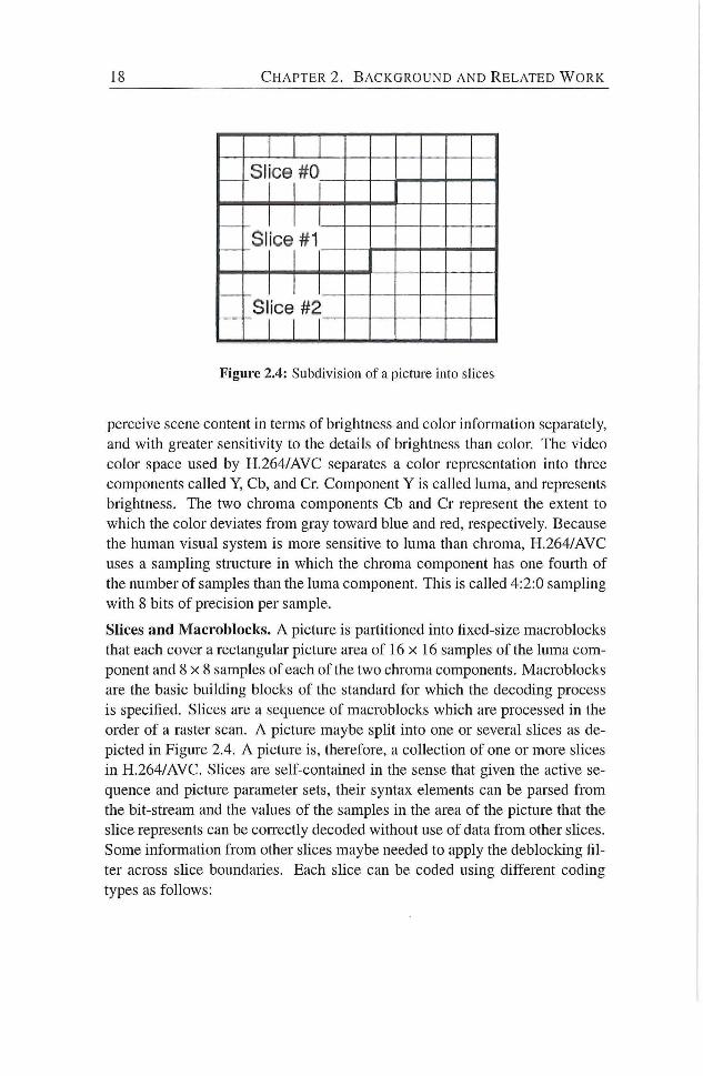
Slices and Macroblocks. A picture is partitioned into fixed-size macroblocks
that each cover a rectangular picture area of 16 x 16 samples of the luma com
ponent and 8 x 8 samples of each of the two chroma components. Macroblocks
are the basic building blocks of the standard for which the decoding process
is specified. Slices are a sequence of macroblocks which are processed in the
order of a raster scan. A picture maybe split into one or several shoes as de
picted in Figure 2.4. A picture is, therefore, a collecdon of one or more slices
in H.264/AVC. Slices are self-contained in the sense that given the active se
quence and picture parameter sets, their syntax elements can be parsed f rom
the bit-stream and the values of the samples in the area of the picture that the
shce represents can be correcdy decoded without use of data f rom other slices.
Some infonnation f rom other shoes luaybe needed to apply the deblocking fil
ter across slice boundaries. Each slice can be coded using different coding
types as follows:
2 . 1 . H . 2 6 4 / A V C V I D E O C O D I N G S T A N D A R D O V E R V I E W 19
X.. :>:, '•• X, 1 X, 1 X , 1 X , >:.- X .
X, 1 X . 1 Xfc 1 x, •< • X.i •'•1 x_
M o d e - 0
V e r t i c a l
| \T-)
' , ' ode - •
H o r i z o n t a l
(HZ)
•>•••
M o d e - 2
DC
M o d e - 0
V e r t i c a l
| \T-)
•>•• ' , ' ode - •
H o r i z o n t a l
(HZ)
>• M o d e - 2
DC y j
M o d e - 0
V e r t i c a l
| \T-) ^ ' , ' ode - •
H o r i z o n t a l
(HZ)
M o d e - 2
DC y j
M o d e - 0
V e r t i c a l
| \T-)
' , ' ode - •
H o r i z o n t a l
(HZ)
M o d e - 2
DC
y j 1'
M o d e - 0
V e r t i c a l
| \T-)
•>':
' , ' ode - •
H o r i z o n t a l
(HZ)
y
M o d e - 2
DC
>•• :<•. X.1 y... Xl X - X j 1 X! 1 Xt 1 Xf Xii Xl X . X.( 1 X J 1 Xi, 1 X.i
y j / / / / / / \ \ \ M o d e - 4
D i a g o n a l
D o w n R i g h t
I D D R )
\ \ \ \ M o d e - 5
V e r t i c a l
R i g h t
(VR)
y- / / Vfode - 3 / ^ D i a g o n a l
^ D o w n L e f t
( D D L )
y- \ \ \ \ M o d e - 4
D i a g o n a l
D o w n R i g h t
I D D R )
y- \ \ \ M o d e - 5
V e r t i c a l
R i g h t
(VR)
y^ / / / Vfode - 3 / ^ D i a g o n a l
^ D o w n L e f t
( D D L )
\ \ \ \ M o d e - 4
D i a g o n a l
D o w n R i g h t
I D D R )
y- \ \ \ \ M o d e - 5
V e r t i c a l
R i g h t
(VR) y j / /
/ Vfode - 3 / ^ D i a g o n a l
^ D o w n L e f t
( D D L ) \ \ \ \
M o d e - 4
D i a g o n a l
D o w n R i g h t
I D D R ) '}'•• H %
M o d e - 5
V e r t i c a l
R i g h t
(VR)
/ Vfode - 3 / ^ D i a g o n a l
^ D o w n L e f t
( D D L )
M o d e - 4
D i a g o n a l
D o w n R i g h t
I D D R )
M o d e - 5
V e r t i c a l
R i g h t
(VR)
X, 1 X< 1 X.J 1X, X.- Xi, x. x^ x . | x j | x , X.. x_ ^ 1 1 t> 1
M o d e - S
H o r i z o n t a l
D o w n
(HO)
/ / / / / M o d e - 7
V e r t i c a l
L e f t
( V L )
M o d e - 8
H o r i z o n t a l
U p
(HU)
y i -.. M o d e - S
H o r i z o n t a l
D o w n
(HO)
y- / / / ./ / M o d e - 7
V e r t i c a l
L e f t
( V L )
V ' M o d e - 8
H o r i z o n t a l
U p
(HU)
y^
M o d e - S
H o r i z o n t a l
D o w n
(HO)
y^ / / /
/ M o d e - 7
V e r t i c a l
L e f t
( V L )
y; .-If"
M o d e - 8
H o r i z o n t a l
U p
(HU) y j '•
>
M o d e - S
H o r i z o n t a l
D o w n
(HO) y- i
/ M o d e - 7
V e r t i c a l
L e f t
( V L ) y '
M o d e - 8
H o r i z o n t a l
U p
(HU)
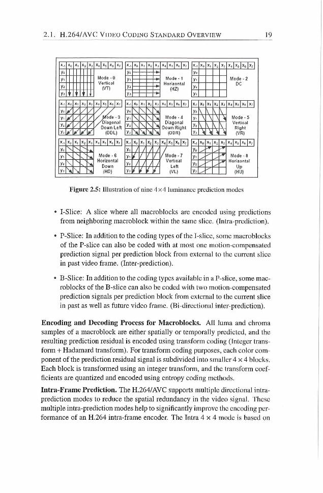
Figure 2.5: Illustration of nine 4x4 luminance prediction modes
• I-Slice: A slice where ah macroblocks are encoded using predictions
f rom neighboring macroblock within the same shce. (Intra-prediction).
• P-Shce: In addition to the coding types of the I-shce, some macroblocks
of the P-shce can also be coded with at most one motion-compensated
prediction signal per prediction block f rom external to the current slice
in past video frame. (Inter-prediction).
• B-Slice: In addition to the coding types available in a P-shce, some mac
roblocks of the B-shce can also be coded with two motion-compensated
prediction signals per prediction block f rom extemal to the current slice
in past as well as future video frame. (Bi-directional inter-prediction).
Encoding and Decoding Process for Macroblocks. A l l luma and chroma
samples of a macroblock are either spatially or temporally predicted, and the
resuldng prediction residual is encoded using transform coding (Integer trans
form -t- Hadamard transform). For transform coding purposes, each color com
ponent of the predicdon residual signal is subdivided into smaller 4 x 4 blocks.
Each block is transformed using an integer transform, and the transform coef
ficients are quantized and encoded using entropy coding methods.
Intra-Frame Prediction. The H.264/AVC supports multiple directional intra-
predicdon modes to reduce the spadal redundancy in the video signal. These
multiple intra-prediction modes help to significantly improve the encoding per
formance of an H.264 intra-frame encoder The Intra 4 x 4 mode is based on
20 C H A P T E R 2. B A C K G R O U N D A N D R E L A T E D W O R K
predicting eacii 4 x 4 luma block separately and is well suited for coding of
parts of a picture with significant detail. The Intra 1 6 x 1 6 mode, on the other
hand, performs prediction of the whole 1 6 x 1 6 luma block and is more suited
for coding very smooth areas of a picture. In addition to these two types of
luma prediction, a separate chroma prediction is conducted. As an alternative
to Intra 4 x 4 and Intra 16 x 16, the standard also provides an option to bypass
the prediction and transform coding process and directly send the values of the
encoded samples using Intra PCM coding type.
When using the Intra 4 x 4 mode, each 4 x 4 block is predicted f rom spadahy
neighboring samples as illustrated in Figure 2.5. The 16 samples of the 4 x
4 block are predicted using prior decoded samples in adjacent blocks labeled
as xO - x7 and yO - y7. For each 4 x 4 block, one of nine prediction modes
can be utilized. In addition to "DC" prediction (where one value is used to
predict the entire 4 x 4 block), eight directional prediction modes are specified
as ihustrated in Figure 2.5. Those modes are suitable to predict directional
structures in a picture such as edges at various angles.
When utilizing the Intra 1 6 x 1 6 mode, the whole luma component of a mac
roblock is predicted. Four prediction modes are supported. Prediction mode
0 (vertical prediction), mode 1 (horizontal prediction), and mode 2 (DC pre
diction) are specified similar to the modes in Intra 4 x 4 prediction except that
instead of 4 neighbors on each side to predict a 4 x 4 block, 16 neighbors on
each side to predict a 16 x 16 block are used. For the specification of predic
tion mode 4 (plane prediction), please refer to [7]. The chroma samples of a
macroblock are predicted using a similar prediction technique as for the luma
component in Intra 1 6 x 1 6 macroblocks, since chroma is usually smooth over
large areas. Intra prediction across shce boundaries is not used, in order to
keep all slices independent of each other
Inter-Frame Prediction. In addition to the intra macroblock coding types,
various predictive or motion-compensated coding types are specified as P mac
roblock types. Each P macroblock type corresponds to a specific partition of
the macroblock into the block shapes used for motion-compensated predic
tion. Partitions with luma block sizes of 16 x 16, 16 x 8, 8 x 16, and 8 x 8
samples are supported by the syntax. In case partitions with 8 x 8 samples
are chosen, one additional syntax element for each 8 x 8 partition is transmit
ted. This syntax element specifies whether the corresponding 8 x 8 paitition
is further partitioned into partitions of 8 x 4, 4 x 8, or 4 x 4 luma samples and
corresponding chroma samples. Figure 2.6 illustrates the partitioning.
Transform, Scaling, and Quantization. Similar to previous video coding
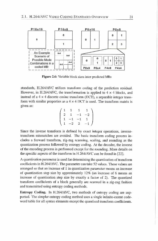
2 .1 . H .264 /AVC V I D E O C O D I N G S T A N D A R D O V E R V I E W 21
P16x16 P16x8 P8x16
An Example Scenario of
Possible Mode Combinations in a
coded MB;
8x4 8x8 8x8
4x0 4x4
P8x8
0 1
2 3
0 0
0 1 0 1
0 •1
0 1 2 3
P8x8 P8x4 P4x8 P4x4
Figure 2.6: Variable block sizes inter-predicted MBs
Standards, H.264/AVC utilizes transform coding of the prediction residual. However, in H.264/AVC, the transformation is applied to 4 x 4 blocks, and instead of a 4 x 4 discrete cosine transform (DCT), a separable integer transform with similar propeilies as a 4 x 4 DCT is used. The transform matrix is given as:
/ 1 1 1 1 \
2 1 - 1 - 2
1 - 1 - 1 1
V 1 - 2 2 - 1 /
Since the inverse transform is defined by exact integer operations, inverse-transform mismatches are avoided. The basic transfonn coding process includes a forward transform, zig-zag scanning, seahng, and rounding as the quandzation process followed by entropy coding. A t the decoder, the inverse of the encoding process is performed except for the rounding. More details on the specific aspects of the transform in H.264/AVC can be found in [22].
A quantization parameter is used for determining the quantization of transform coefficients in H.264/AVC. The parameter can take 52 values. These values are arranged so that an increase of 1 in quantization parameter means an increase of quantization step size by approxiinately 12% (an increase of 6 means an increase of quantization step size by exactly a factor of 2). The quantized transform coefficients of a block generahy are scanned in a zig-zag fashion and transmitted using entropy coding methods.
Entropy Coding. In H.264/AVC, two methods of entropy coding are supported. The simpler entropy coding method uses a single infinite-extent codeword table for all syntax elements except the quantized transform coefficients.
22 C H A P T E R 2. B A C K G R O U N D A N D R E L A T E D W O R K
Thus, instead of designing a different V L C table for each syntax element, only
the mapping to the single codeword table is custoiTiized according to the data
statistics. The single codeword table chosen is an exp-Goloinb code with very
simple and regular decoding properdes.
For transmitdng the quantized transform coefficients, a more efficient method
called Context-Adaptive Variable Length Coding (CAVLC) is employed. In
this scheme, V L C tables for various syntax elements are switched depending
on already transmitted syntax elements. Since the V L C tables are designed
to match the corresponding conditioned statistics, the entropy coding perfor
mance is improved in comparison to schemes using a single V L C table. The
efficiency of entropy coding can be improved further i f the Context-Adaptive
Binary Arithmetic Coding (CABAC) is used. Compared to CAVLC, CABAC
typically provides a reduction in bit rate between 5%-15% [23].
In-Loop Deblocking Filter. One particular characteristic of block-based cod
ing is the accidental production of visible block structures. Block edges are
typically reconstructed with less accuracy than interior pixels and "blocking"
is generally considered to be one of the most visible artifacts wi th the present
compression methods. For this reason, H.264/AVC defines an adaptive in-loop
deblocking filter, where the strength of filtering is controlled by the values of
several syntax elements.
The basic idea of deblocking filter is that i f a relatively large absolute dif
ference between samples near a block edge is measured, it is quite hkely a
blocking artifact and should therefore be reduced. However, i f the magnitude
of that difference is so large that it cannot be explained by the coarseness of the
quantization used in the encoding, the edge is more likely to reflect the actual
behavior of the source picture and should not be smoothed over. The deblock
ing filter in H.264/AVC reduces the blockiness while keeping the sharpness
of the content unchanged. Consequently, the subjective quahty is significantly
improved. The filter reduces the bit rate typically by 5%-10% while producing
the same objective quahty as the non-filtered video. A detailed description of
the adaptive deblocking filter can be found in [24].
2.2 Overview of the p-YEX VLIW Processor ^
p-YEX is an open source, extensible, and reconfigurable, soft-core V L I W pro
cessor. The processor architecture is based on the V E X ( V L I W Example)
^The overview of the r-VEX V L I W is extracted from [25]
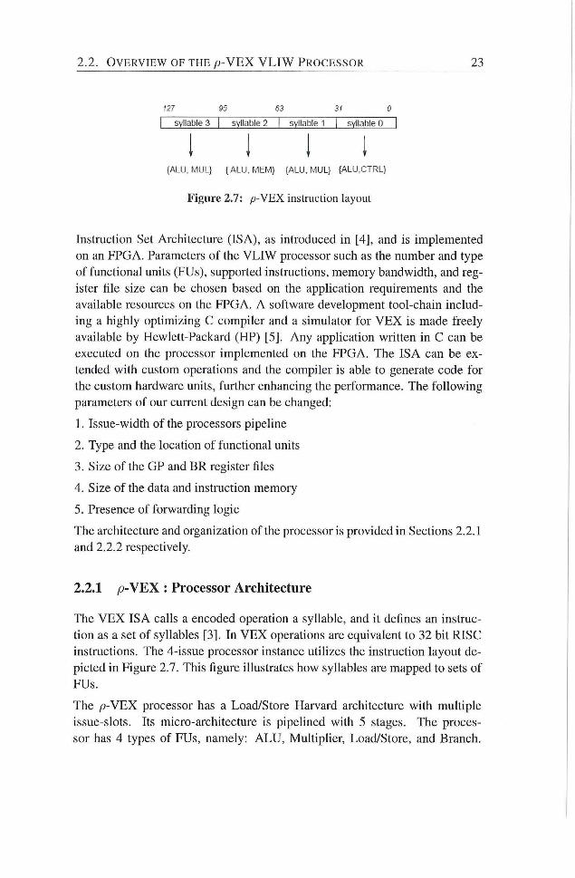
2.2. O V E R V I E W OF T H E p-YEX V L I W PROCESSOR 23
127 95 63 31 0
I syllables | syllatjle 2 | syllable 1 | syllable 0 |
{ALU, MUL} {ALU. MEM} {ALU, MUL} {ALU.CTRL}
Figure 2.7: p - V E X instruction layout
Instruction Set Architecture (ISA), as introduced in [4], and is implemented
on an FPGA. Parameters of the V L I W processor such as the number and type
of funcdonal units (FUs), supported instructions, memory bandwidth, and reg
ister file size can be chosen based on the applicadon requirements and the
available resources on the FPGA. A software development tool-chain includ
ing a highly optimizing C compiler and a simulator for V E X is made freely
available by Hewlett-Packard (HP) [5]. Any apphcation written in C can be
executed on the processor implemented on the FPGA. The ISA can be ex
tended with custom operations and the compiler is able to generate code for
the custom hardware units, further enhancing the performance. The fol lowing
parameters of our current design can be changed:
1. Issue-width of the processors pipeline
2. Type and the location of functional units
3. Size of the GP and BR register files
4. Size of the data and instruction memory
5. Presence of forwarding logic
The architecture and organization of the processor is provided in Sections 2.2.1
and 2.2.2 respectively.
2.2.1 p - V E X : Processor Architecture
The V E X ISA calls a encoded operation a syllable, and it defines an instruc
tion as a set of syllables [3]. In V E X operations are equivalent to 32 bit RISC
instructions. The 4-issue processor instance utihzes the instruction layout de
picted in Figure 2.7. This figure illustrates how syhables are mapped to sets of
FUs.
The p-YEX processor has a Load/Store Harvard architecture with multiple
issue-slots. Its micro-architecture is pipehned with 5 stages. The proces
sor has 4 types of FUs, namely: A L U , Multiplier, Load/Store, and Branch.
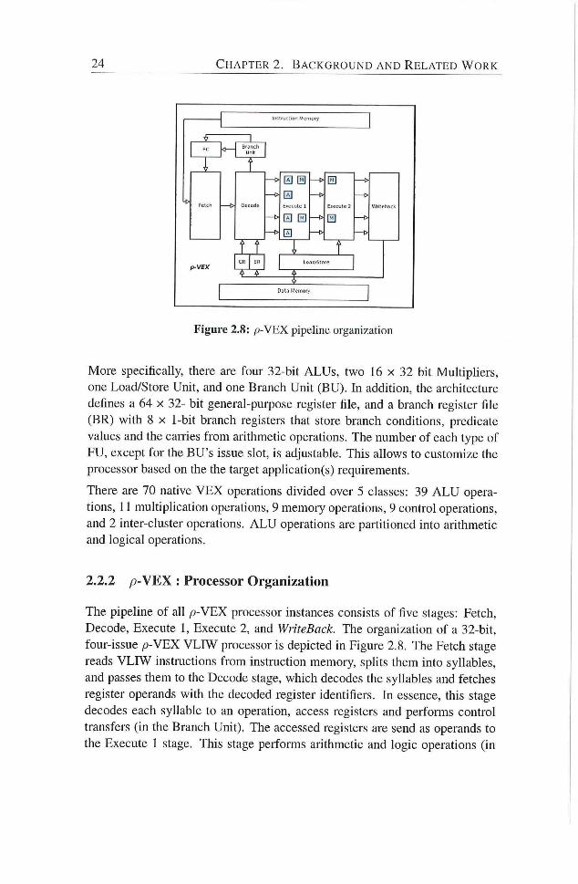
24 C H A P T E R 2. B A C K G R O U N D A N D R E L A T E D W O R K
0 0
0 Decode Execute 1
0
0
E>ecu!e 2
0
Figure 2.8: p - V E X pipeline organization
More specifically, there are four 32-bit ALUs, two 16 x 32 bit Multiphers,
one Load/Store Unit, and one Branch Unit (BU). In addidon, the architecture
defines a 64 x 32- bit general-purpose register file, and a branch register file
(BR) with 8 X 1-bit branch registers that store branch conditions, predicate
values and the canies f rom arithmetic operations. The number of each type of
FU, except for the BU's issue slot, is adjustable. This allows to customize the
processor based on the the target applicadon(s) requirements.
There are 70 native V E X operations divided over 5 classes: 39 A L U opera-
dons, 11 multiphcadon operadons, 9 memory operadons, 9 control operadons,
and 2 inter-cluster operations. A L U operations are partitioned into arithmetic
and logical operations.
2.2.2 / 9 -VEX : Processor Organization
The pipeline of all /3-VEX processor instances consists of five stages: Fetch,
Decode, Execute 1, Execute 2, and WriteBack. The organization of a 32-bit,
four-issue p -VEX V L f W processor is depicted in Figure 2.8. The Fetch stage
reads V L I W instructions f rom instruction memory, sphts them into syllables,
and passes them to the Decode stage, which decodes the syhables and fetches
register operands with the decoded register identifiers. In essence, this stage
decodes each syhable to an operation, access registers and performs control
transfers (in the Branch Unit). The accessed registers are send as operands to
the Execute 1 stage. This stage performs arithmetic and logic operations (in
2.3. R E L A T E D W O R K 25
the A L U and M U L units) on hs operands. The Execute 2 stage performs a
pre-selection of functional results for the commit stage and does the store or
load phase of data memory operations in the load/store unit. The WriteBack
stage performs all write activides and avoids read-after-write data hazards that
are created by the decode stage. The register file write targets can be in the
General Purpose Register file (GR) and/or in the Branch Register file (BR).
The data memory of the processor is implemented by udhzing the Block R A M
(BRAMs) that are provided by the FPGA.
2.3 Related Work
This section presents the prominent related work for design of low-power,
area-efficient and high-throughput video processing units in H.264/AVC. It
covers both the ASIC as weh as FPGA based soludons. In-loop deblock
ing filter designs are presented in Secdon 2.3.1. The related work for intra-
predicdon unit in H.264/AVC is hsted in Secdon 2.3.2, fohowed by the state-
of-the-art presented in the hterature for forward (inverse) integer transform
units i n H.264/AVC in Secdon 2.3.3.
2.3.1 In-loop Deblocking Filter
From a low-power deblocking filter hardware design point of view, a num
ber of architectures and their hardware implementations have been presented
in hterature for last few years [24, 26-56]. For instance, in [44, 45], the au
thors presented two different low-power hardware implementations for the de
blocking filter Their design consists of a 2-stage pipeline datapath. The first
pipehne stage includes a 12-bit adder and two shifters. The second stage in
cludes a 12-bit comparator, several two's complement units and multiplexers
for conditional branching. The dynamic power consumption of the deblocking
filter is significantly reduced with such a simplified datapath. However, be
cause of lack of sufficient storage registers, the intermediate results are to be
stored and fetched f rom the memory several times during filtering processing.
This results in a large number of cycles to process a single M B (5248 cycles
/ M B ) . Therefore, the throughput of the proposed design is reduced quite sig
nificantly. Moreover, no attempts were made, or at least reported to remove
the redundancy in the deblocking filter algorithm. The hardware implemen
tation of proposed design works at 72 M H z in a Xi l inx Virtex E FPGA and
can process up to Common Intermediate Format (CIF, 352 x 288) video frame
26 C H A P T E R 2. B A C K G R O U N D A N D R E L A T E D W O R K
resolution only.
Similarly, Byung-Joo, et al., also proposed a low-power deblocking filter in
[36]. They attempt to reduce the dynamic power consumption by skipping fil
tering process completely or partially by exploidng the reladonship between
block level encoding parameters and filtering conditions. The proposed design,
however, requires 2272 cycles to process one M B and, therefore, can only pro
cess up to CCIR601 video frame format (704x576) in real-dme. The proposed
design though provides better throughput, but still do not meet the real-time
processing requirement of a wide range of portable multimedia devices where
standard-definidon (SD, 720x480) , high-definidon (HD, 1280x720) or even
higher resoludons are to be supported.
Recently, Nam Thang, et al., [43] also proposed a low-power, high-throughput
4-stage pipelined architecture, implemented using 0 .18 p m CMOS standard
cell technology, for deblocking filter in H.264/AVC. Four stages pipehne im
plementadon of deblocking filter and hybrid processing order enable them to
process a single macroblock in 192 cycles. Whde working at 220 MHz , it can
provide a throughput up to 1146 K MB/s. The filter core consumes 34. 8 p W
for QCIF frame resolution at an operating frequency of 220 MHz . The pro
posed design uses five 4 x 4 block buffers for intermediate result storage dur
ing M B processing to achieve high throughput and attempts to reduce power
consumption by adopdng clock gadng for these blocks. However, no such
attempts are made for 2"'' and 3' '' pipeline stages where most of the filter pro
cessing take place. Moreover, no pardal or f u l l filtering process skipping sce
narios are taken care o f f in the proposed architecture to reduce the dynamic
power
From real-time video processing applications point of view, a large number
of deblock filter accelerators using single filter unit have been presented in
the literature. For instance, in [46], Shih, et al., propose a 5-stage pipelined
hardware architecture for deblocking filter They employ a novel filtering order
and data reuse strategy to reduce the number of cycles, memory traffic and
required area for their implementation. The authors of [32] re-an-ange the data
flow to significantly reduce the memory size requirement and propose in-place
architecture which re-uses the intermediate data as soon as it is available and
thus are able to reduce the intermediate data storage to four 4 x 4 blocks instead
of a complete 16x16 macroblock . Sintiilarly Chang in [31] also re-orders the
computing flow to efficiently use the intermediate data between the adjacent
edges in their proposed architecture.
The hardware architecture in [52] implements a parallel-in parallel-out recon-
2.3. R E L A T E D W O R K 27
figurable FIR filter to carry out the filtering operations and uses a dual port
SRAM for intermediate data storage. L i , et al., [38] adopt a 2 dimensional
parallel memory scheme for parallel access in both the horizontal and vertical
directions to speed up the fihering process and also eliminate the need of a
transpose circuitry by using this memory scheme efficiently.
A hybrid filter scheduling described in [40] reduces required number of clock
cycles for filtering and thus improves the system throughput while using
the column-of-pixel data anangement to facilitate the memory accesses and
reusing the pixel value. A 5-stage pipehned architecture proposed in [29] for
simultaneous processing of strong and weak filtering modes uses a novel trans
pose design to reduce the hardware cost and an alternate processing order of
verdcal and horizontal edges to reduce the on-chip memory requirement.
The area requirement for some of these hardware accelerators [38] [31] [56],
is significandy low. This reduction in area requirement is because of their re
duced funcdonality as these architectures do not implement boundary strength
(BS) computation module.
Some of the hardware soludons based on multiple filter units are also intro
duced in the literature quite recendy. These solutions provide higher through
put at the cost of additional on-chip area, but stih most of these soludons do
not meet the throughput requirements of all the levels (level 1-5.2) offered
by the video Ccodec H.264/AVC. For instance, F. Tobajas based on a double-
filter strategy, and using a raster scan filtering order, proposes a hardware ar
chitecture in [48]. Cheng in [27] [28]proposes a configurable window based
architecture to simultaneously filter in both the directions. The main idea is
to reduce the number of memory references through simultaneous processing
architecture (SPA) using the vertical processing order instead of the raster scan
order. A similar architecture is proposed in [53] by Venkatraman, et al.
Some efforts are also made to optimize the filter kernels by removing redun
dant operations, however the strong filter mode is the main focus in most of
these attempts. For instance, in [49], the author suggest 3 different decom
positions of the filter kernels in Strong filter mode to reduce the number of
addition operations. The author however, do not consider similar decomposi
tions for Weak Filter mode.
In shoit, single filter unit based solutions require less area in terms of equiv
alent gate count fort their implementation but fa i l to meet the processing re
quirements of high definidon video in real-time. In some of the cases area
reduction is achieved through reduced functionality offered by these hardware
designs. The soludons based on multiple filtering units, on the other hand,
28 C H A P T E R 2. B A C K G R O U N D A N D R E L A T E D W O R K
though provide better throughput at the cost of additional area but still do not
meet the real-dme processing requirement of ah the levels offered by the video
coding standard H.264/AVC.
2.3.2 Intra Prediction
Many different variants of intra-predicdon algorithm has been presented in
literature for last few years [47, 57-73]. The recent research on H.264/AVC
intra predicdon has focused on efficient hardware designs. The work pre
sented in [71] proposes a hardware design with 5-stage registers and three
configurable data paths for intra prediction unit. It uses reconfigurable pre
dictor generators that exploit inherent parallehsm within one predicdon mode.
The proposed design can process approximately 100 V G A frames in real-dme.
The proposed design, process each predicdon mode individuahy and therefore,
does not exploit the f u h space of opdmizadon and parallehsm between the dif
ferent intra prediction modes. Since the proposal made in this work processes
the intra prediction modes sequentially. Consequently, i t requires a relatively
higher frequency to achieve a throughput of 100 V G A frames in real-time.
Moreover, it also suffers f rom overhead of configuring the hardware for differ
ent predicdon modes.
In [68], an efficient intra-frame codec is proposed. The proposed solution can
process 720p @ 30 fps in real-time and can be used for both the encoder and
decoder implementations. This soludon, however, excludes the plane mode for
16x16 luma and 8 x 8 chroma blocks. The proposed solution, therefore, can
be used in a matched encoder-decoder scenarios only where it is guaranteed
that plane mode is not used for intra-predicdon.
High-throughput hardware designs for a H.264/AVC decoder are proposed
i n [47] and [65]. The proposed designs can process high-definidon (HD)
video in real-time. Since no attempts were made to optimize the intra pre
diction algorithm to reduce the arithmetic operations, therefore, the hardware
implementation of these designs cost significant amount of hardware resources
(approximately 29K gates).
Similarly, in [72], an efficient hardware implementation for intra-prediction
unit is proposed. The design targets the H.264/AVC encoder and uses a so-
called combined module approach to generate a subset of intra-prediction
modes in parallel. Furthermore, the intra-prediction algorithm is opdmized to
significantly reduce the number of arithmetic operadon for the computation of
predicdon samples. The proposed soludon, however, does not fu l ly eliminate
2.4. S U M M A R Y 29
the redundancy in the algorithm and also primarily targets the H.264 encoder.
2.3.3 Integer Transform
A number of efficient algorithms and hardware designs for forward and
inverse-integer transform in H.264/AVC, are presented in literature in recent
past [22,64,74-94] .From the perspective of hardware designs for integer trans
form in H.264/AVC, the main focus of research has been to develop fast algo
rithms with reduced on-chip area for its hardware implementation. In [82], L i u
et a l , used a parallel register array to realize the transpose operation for the 2D
4 x 4 forward integer transform. In [89], Cheng proposed high-throughput 4 x 4
integer transform architecture with no transpose memory requirement. Fan, et
al., proposed a fast 2D transform algorithm in [79]. Similarly in [88,93,95], a
number of fast algorithms for the integer transform have been proposed.
The H.264/AVC encoder utilizes multiple transforms (Forward/Inverse) in
teger transform and (Forward/Inverse) Hadamard Transform. Therefore, re
cently, the research focus has been shifted to design a unified transform unit to
support multiple transforms in H.264/AVC [80], [94], [90], [92]. The motiva
tion for such efforts is to reduce the on-chip area for the hardware implemen
tadon of these transforms units by sharing area between them. The proposed
architectures although support multiple transforms in H.264/AVC, but most of
them provide only one type of transform at a time. A l l of these architectures
take residual data as an input and provide the transformed coefficients for the
selected type of transform at the output.
2.4 Summary
In this chapter, we have presented an overview of the latest and state-of-the-
art video coding standard H.264/AVC. Different functional units of the video
codec are briefly described and the compute-intensive units are idendfied. A f
terward, /9-VEX Reconfigurable V L I W processor is introduced. The proces
sor's architecture and design is also explained. Finally, the related work for
the idendfied compute-intensive video coding funcdonal units in H.264/AVC
is presented in this chapter.

3 Deblocking Filter
THE adaptive deblocking filter in H.264/AVC not only provides perceptu
ally improved video quality by removing blocking artifacts in the recon-
stmcted video frames, but also helps to reduce bit-rate typically between 5%
-10% [2]. However, this improvement in video quality and reduction in video
bit-rate is achieved at the cost of increased complexity of deblocking filter al
gorithm.
The complexity of deblocking filter algorithm in H.264/AVC is mainly based
on high adaptivity of the filter, which requires conditional processing on block
edge and sample levels. Another reason for high complexity is small block
size employed for residual coding in H.264/AVC coding algorithms. With 4 x 4
blocks and a typical filter length of 2-samples in each direction, almost every
sample in a video frame must be loaded f rom memory, either to be modified
or to determine i f neighboring samples w i l l be modified.
According to analysis of run-time profile of H.264/AVC decoder sub-
functions, deblocking filter consumes about one-third of the total computa
tional resources required for video decoder [96], This is true even though
the deblocking filter can be implemented without any muUiphcation or divi
sion operations. These demanding characteristics suggest a high-throughput
implementation for such a filter, especially for High Definition (HD) video ap
plications such as Digital T V (DTV) , where even larger frame-size at higher
frame-rate is to be processed in real-time. Similarly a low-power solution is
required for portable battery-powered multimedia electronic devices, such as
mobile phones, digital cameras, and Personal Dighal Assistant (PDA).
The main contributions of this chapter are:
1. For image processing apphcations, a single-filter-unit based low-power
hardware design for deblocking filter in H.264/AVC.
31
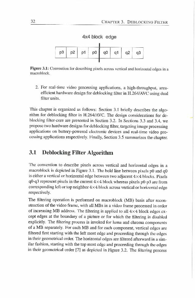
32 C H A P T E R 3. D E B L O C K I N G F I L T E R
4x4 block edge
p3 p2 P1 pO qO q1 q2 q3
Figure 3.1: Convention for describing pixels across vertical and horizontal edges in a
macroblock.
2. For real-time video processing apphcations, a high-throughput, area-
efficient hardware design for deblocking filter in H.264/AVC using dual
filter units.
This chapter is organized as follows: Section 3.1 briefly describes the algo
rithm for deblocking filter in H.264/AVC. The design considerations for de
blocking filter-core are presented in Secdon 3.2. In Sections 3.3 and 3.4, we
propose two hardware designs for deblocking filter, targeting image processing
applications on batteiy-powered electronic devices and real-time video pro
cessing applications respectively. Finally, Section 3.5 summarizes the chapter.
3.1 Deblocking Filter Algorithm
The convention to describe pixels across veilical and horizontal edges in a
macroblock is depicted in Figure 3.1. The bold hne between pixels pO and qO
is either a vertical or horizontal edge between two adjacent 4 x 4 blocks. Pixels
qO-q3 represent pixels in the current 4 x 4 block whereas pixels pO-p3 are f rom
corresponding left or top neighbor 4 x 4 block across vertical or horizontal edge
respectively.
The filtering operation is peiformed on macroblock (MB) basis after recon
struction of the video frame, with all MBs in a video frame processed in order
of increasing M B address. The filtering is applied to all 4 x 4 block edges ex
cept edges at the boundary of a picture or for which the filtering is disabled
explicitly. The filtering process is invoked for luma and chroma components
of a M B separately. For each M B and for each component, vertical edges are
filtered first starting with the left most edge and proceeding through the edges
in their geometrical order. The horizontal edges are filtered afterward in a sim
ilar fashion, starting with the top most edge and proceeding through the edges
in their geometrical order [7] as depicted in Figure 3.2. The filtering process
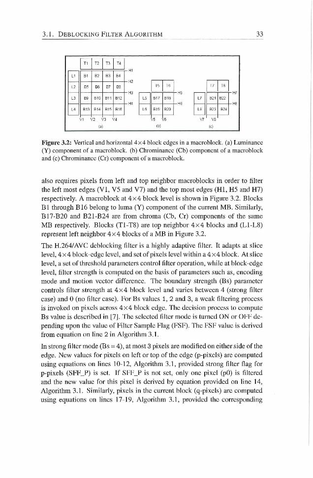
3.1 . D E B L O C K I N G F I L T E R A L G O R I T H M 33
B-:
B13
57
- H I
- H 2
-H3
- H 4
(a)
-H5
-H6
\ 7 VA
Figure 3.2: Vertical and horizontal 4x4 block edges in a macroblock. (a) Luminance (Y) component of a macroblock. (b) Chrominance (Cb) component of a macroblock and (c) Chrominance (Cr) component of a macroblock.
also requires pixels f rom left and top neighbor macroblocks in order to filter
the left most edges ( V I , V5 and V7) and the top most edges ( H I , H5 and H7)
respectively. A macroblock at 4 x 4 block level is shown in Figure 3.2. Blocks
B l through B16 belong to luma (Y) component of the current M B . Similarly,
B17-B20 and B21-B24 are f rom chroma (Cb, Cr) components of the same
M B respectively. Blocks (T1-T8) are top neighbor 4 x 4 blocks and (L1-L8)
represent left neighbor 4 x 4 blocks of a M B in Figure 3.2.
The H.264/AVC deblocking filter is a highly adaptive filter. It adapts at slice
level, 4 x 4 block-edge level, and set of pixels level within a 4 x 4 block. A t slice
level, a set of threshold parameters control filter operation, while at block-edge
level, filter strength is computed on the basis of parameters such as, encoding
mode and modon vector difference. The boundary strength (Bs) parameter
controls filter strength at 4 x 4 block level and varies between 4 (strong filter
case) and 0 (no filter case). For Bs values 1, 2 and 3, a weak filtering process
is invoked on pixels across 4 x 4 block edge. The decision process to compute
Bs value is described in [7]. The selected filter mode is turned O N or OFF de
pending upon the value of Filter Sample Flag (FSF). The FSF value is derived
f rom equadon on hne 2 in Algorithm 3.1.
In strong filter mode (Bs = 4), at most 3 pixels are modified on either side of the
edge. New values for pixels on left or top of the edge (p-pixels) are computed
using equations on hnes 10-12, Algorithm 3.1, provided strong filter flag for
p-pixels (SFF_P) is set. I f SFF_P is not set, only one pixel (pO) is filtered
and the new value for this pixel is deiived by equadon provided on hne 14,
Algori thm 3.1. Similarly, pixels in the cuiTcnt block (q-pixels) are computed
using equations on hnes 17-19, Algorithm 3.1, provided the corresponding
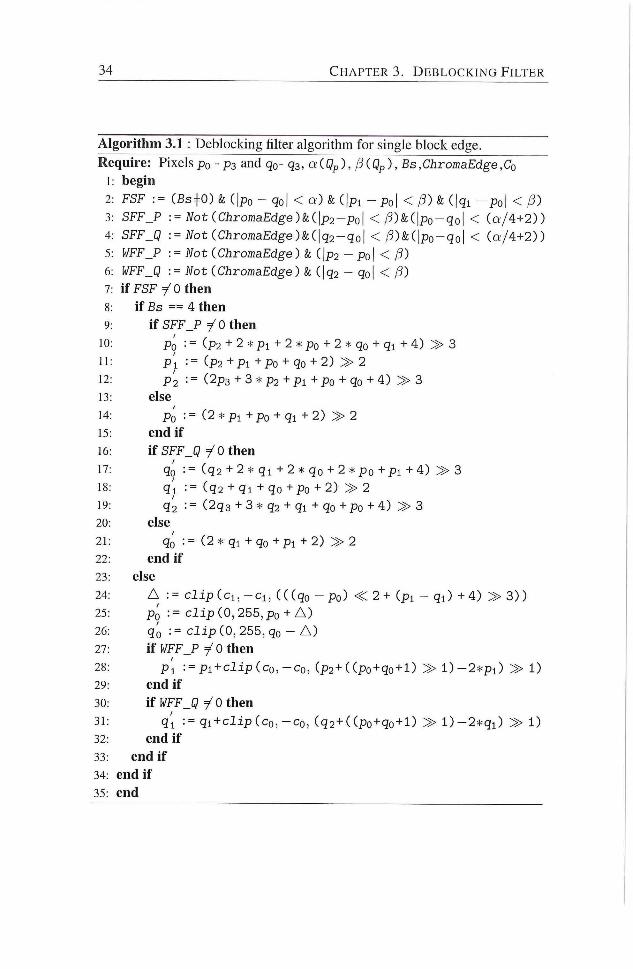
34 C H A P T E R 3. D E B L O C K I N G F I L T E R
Algorithm 3.1 : Deblocking filter algorithm for single block edge.
Require: Pixels po - ps and qo- qa, aiQp), /S(Qp), Bs,ChromaEdge,Co
begin
FSF := (Bs=|=0)& (|po - qo| < Q ' ) & ( | p i - p o | < ( | q i - p o | < P)
SFF_P := Not(ChromaEdge)ki\p2-po\ < / 3 ) & ( | p o - q o | < ( a ' / 4+2) )
SFF_Q := Not iChromaEdge)k(\q2-qo\ < / 3 )&( |po -qo | < ( Q ' / 4 + 2 ) )
WFF_P — Not (ChromaEdge) & ( |p2 - Po| < /3)
WFF_Q := Not (ChromaEdge) & (jqs - qoj < /3)
i f F S F 7^0 then
if Bs == 4 then
if SFF_P T'O then
Po : = (P2 + 2 * Pl + 2 * Po + 2 * qo + qi + 4) > 3
p'l : = ( p 2 + P i + P o + qo + 2) > 2
p'2 : = (2p3 + 3 * p2 + Pl + Po + go + 4) » 3
else
Po := (2 * p i +po + qi + 2) » 2
end if
if SFF_Q i 0 then
qó := ( q 2 + 2 * q i + 2 * qo + 2 *po + p i + 4 ) » 3
q'l := ( q 2 + q i + qo +Po + 2) > 2
q2 : = (2q3 + 3 * q2 + q i + qo + po + 4) » 3
else
qó := (2 * qi + qo + p i + 2 ) » 2
end if
else
A := c l i p ( c i , - c i , ( ( (qo - p o ) <C 2 + ( p i - q i ) + 4 ) » 3 ) )
Po := c l i p (0, 255, po + A )
qó := c l i p (0, 255, qo - A )
'\ÏWF_P yOthen
p ' l : = p i + c I i p ( c o , - c o , (p2+( (po + qo + l ) » l ) - 2 * p i ) » 1)
end if
\iWF_Q 7^Othen
q'l := q i + c I i p ( c o , - C Q , ( q 2 + ( ( p o + qo + D » l ) - 2 * q i ) » 1)
end if
end if
end if
end
3.2. D E S I G N C O N S I D E R A T I O N FOR D E B L O C K I N G F I L T E R C O R E 35
strong filter flag (SFF_Q) is set. In case SFF_Q is not set, only one pixel (qO)
is filtered using equation provided on line 21 Algorithm 3.1 and rest of the
pixels remain unchanged. The values for SFF_F and SFF_Q flags are derived
f rom equations described on lines 2 and 3, in Algorithm 3.1 respectively.
In weak filter mode (Bs = 1, 2 or 3), at most 2 pixels on either side of the edge
are filtered. The new values for pixels pO and qO across the edge are derived
f rom equations on hnes 25 and 26 in Algori thm 3.1 respectively. Similarly,
equadons on lines 28 and 31 in Algori thm 3.1 are used to compute filtered val
ues for pixels p l and q l , provided the corresponding weak filter flag (WFF_P,
WFF_Q) is set. In case weak filter flag is not set, filtering operation for these
pixels is turned off.. The values for WFF_P and WFF_Q are derived f rom
equadons on lines 5 and 6, Algorithm 3.1. No filtering is apphed for Bs = 0.
3.2 Design Consideration for Deblocking Filter Core
In this section, we elaborate on the opdmizations carried out at deblocking
filter algorithm level. Other design-level considerations along with their justi
fication and/or motivadon are also described, for low-power and area-efficient
hardware design for core filtering unit in deblocking filter.
3.2.1 Processing Units for Luma and Chroma Components
The H.264/AVC supports Y U V 4:2:0, Y U V 4:2:2, and Y U V 4:4:4 video frame
formats. In case of Y U V 4:2:0, 33% of pixels belong to chroma component
of a macroblock. This number increases to 50%, and 66% for Y U V 4:2:2
and Y U V 4:4:4 video frame formats respectively. Since the chroma filtering
is much cheaper than the luma filtering in terms of required arithmetic opera
tions (13 vs. 45), i t is potendally beneficial to design separate processing units
for luma and chroma components of a macroblock. These separate luma-,
chroma-processing units, depending upon the status of ChromaEdge flag ( A l
gorithm 3.1), can be enabled or disabled independent of each other to reduce
the dynamic power consumpdon.
3.2.2 Processing Units for Strong and Weak Filter Modes
For both luma and chroma components of a M B , the filter mode for pixels
across any edge is determined on the basis of Bs value for that edge. Since
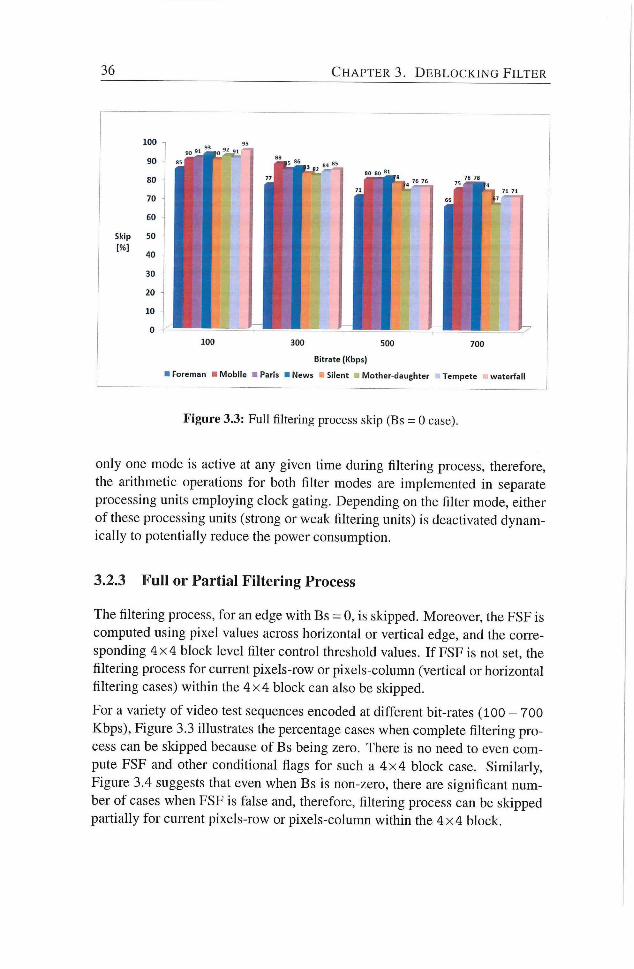
36 C H A P T E R 3. D E B L O C K I N G F I L T E R
Figure 3.3: Full filtering process skip (Bs = 0 case).
only one mode is active at any given time during filtering process, therefore,
the arithmetic operations for both filter modes are implemented in separate
processing units employing clock gating. Depending on the filter mode, either
of these processing units (strong or weak filtering units) is deactivated dynam
ically to potentiahy reduce the power consumption.
3.2.3 Ful l or Partial Filtering Process
The filtering process, for an edge with Bs = 0, is skipped. Moreover, the FSF is
computed using pixel values across horizontal or verdcal edge, and the C O I T C -
sponding 4 x 4 block level filter control threshold values. I f FSF is not set, the
filtering process for current pixels-row or pixels-column (vertical or horizontal
filtering cases) within the 4 x 4 block can also be skipped.
For a variety of video test sequences encoded at different bit-rates (100 - 700
Kbps), Figure 3.3 illustrates the percentage cases when complete filtering pro
cess can be skipped because of Bs being zero. There is no need to even com
pute FSF and other conditional flags for such a 4 x 4 block case. Similarly,
Figure 3.4 suggests that even when Bs is non-zero, there are significant num
ber of cases when FSF is false and, therefore, filtering process can be skipped
pardally for current pixels-row or pixels-column within the 4 x 4 block.
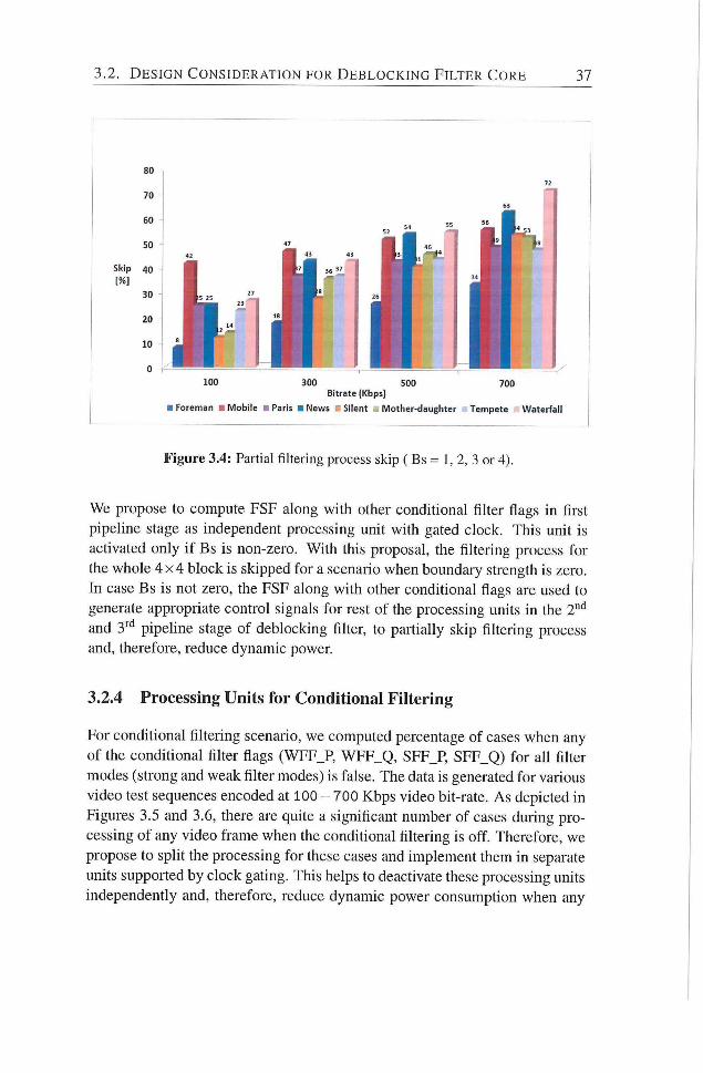
3.2. D E S I G N C O N S I D E R A T I O N FOR D E B L O C K I N G F I L T E R C O R E 37
Figure 3.4: Partial fil tering process skip ( Bs = 1, 2, 3 or 4).
We propose to compute FSF along with other conditional filter flags in first
pipeline stage as independent processing umt with gated clock. This unit is
activated only i f Bs is non-zero. With this proposal, the filtering process for
the whole 4 x 4 block is skipped for a scenario when boundary strength is zero.
In case Bs is not zero, the FSF along with other conditional flags are used to
generate appropriate control signals for rest of the processing units in the 2"''
and 3'"'' pipehne stage of deblocking filter, to paitially skip fikering process
and, therefore, reduce dynamic power.
3.2.4 Processing Units for Conditional Filtering
For condidonal filtering scenario, we computed percentage of cases when any
of the conditional filter flags (WFF_P, WFF_Q, SFF_P, SFF_Q) for all fiher
modes (strong and weak filter modes) is false. The data is generated for various
video test sequences encoded at 100 - 700 Kbps video bh-rate. As depicted in
Figures 3.5 and 3.6, there are quite a significant number of cases during pro
cessing of any video frame when the conditional filtering is off. Therefore, we
propose to split the processing for these cases and implement them in separate
units supported by clock gating. This helps to deactivate these processing units
independently and, therefore, reduce dynamic power consumpdon when any
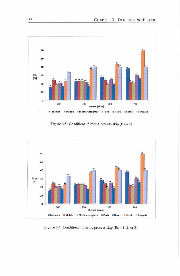
38 C H A P T E R 3. D E B L O C K I N G F I L T E R
100 300 500 700 Bitrate (Kbps)
• Foreman • Mobile Mother-daughter • Paris • News Silent Tempete
Figure 3.5: Conditional filtering process skip (Bs = 4).
100 300 500 700 Bitrate (Kbps)
• Foreman • Mobile i Mother-daughter • Paris • News Silent Tempete
Figure 3.6: Conditional filtering process skip (Bs = 1, 2, or 3).
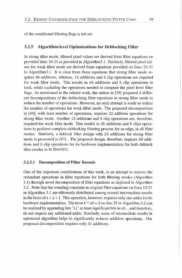
3.2. D E S I G N C O N S I D E R A T I O N FOR D E B L O C K I N G F I L T E R C O R E 39
of the conditional filtering flags is not set.
3.2.5 Algorithm-level Optimizations for Deblocking Filter
In strong filter mode, filtered pixel values are derived f rom filter equations on
provided lines 10-21 as provided in Algorithm3.1. Similarly, filtered pixel val
ues for weak filter mode are derived f rom equadons provided on lines 24-31
in Algorithm3.1. It is clear f rom these equations that strong filter mode re
quires 36 additions; whereas, 13 additions and 5 chp operations are required
for weak filter mode. This resuhs in 49 additions and 5 chp operations in
total, while excluding the operations needed to compute the pixel level filter
flags. As mentioned in the related work, the author in [49] proposed 3 differ
ent decompositions of the deblocking filter equations in strong filter mode to
reduce the number of operations. However, no such attempt is made to reduce
the number of operations for weak filter mode. The proposed decomposition
in [49], with least number of operations, requires 22 addition operations for
strong filter mode. Another 13 additions and 5 clip operations are, therefore,
required for weak filter mode. This results in 35 additions and 5 clips opera
tions to perform complete deblocking filtering process for an edge, in all filter
modes. Similarly, a deblock filter design with 23 additions for strong filter
mode is presented in [97] . The proposed design, therefore, requires 36 addi
tions and 5 clip operations for its hardware implementation for both deblock
filter modes in H.264/AVC.
3.2.5.1 Decomposition of Filter Kernels
One of the important contributions of this work, is an attempt to remove the
redundant operations in filter equations for both filtering modes (Algorithm
3.1) through novel decomposition of filter equations as depicted in Algorithm
3.2 . Note that the rounding constants in original filter equations on lines 10-21
in Algori thm 3.1 are efficiently distributed among several intermediate results
in the form of x H- y -H I . This operation, however, requires only one adder for its
hardware implementation. The term 4 * uO - I - 3 on line 25 in Algorithm 3.2 can
be reahzed by appending bits ' 11 ' as least significant bits in uO. , and therefore,
do not require any additional adder. Similarly, reuse of intermediate results in
optimized algorithm helps to significandy reduces addition operations. Our
proposed decomposition requires only 31 additions.
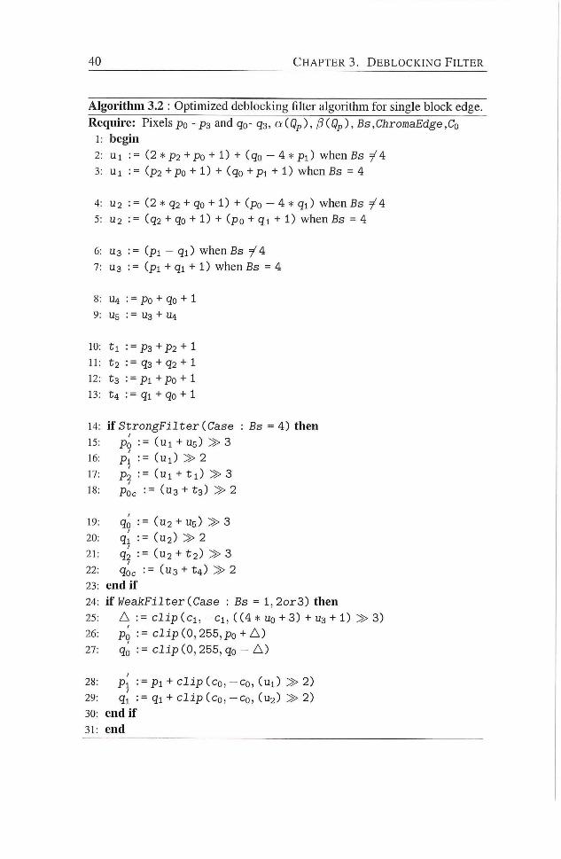
40 C H A P T E R S . D E B L O C K I N G F I L T E R
Algorithm 3.2 : Optimized deblocking filter algorithm for single block edge.
Require: Pixels po - ps and qo- qa, a(Qp), jiiQp), Bs,ChromaEdge,Co
1: begin
2: U l : = (2 * p 2 +Po + 1) + (qo - 4 * P l ) when Bs y^A
3: U l : = ( p 2 +po + 1) + (qo + P i + 1) when Bs = 4
4: U2 := (2 * q2 + qo + 1) + (po - 4 * q i ) when Bs 7^4
5: U2 : = ( q 2 + qo + 1) + (po + q i + 1) when Bs = 4
6: U3 := ( p i - q i ) when Bs =/ A
7: 0 3 : = ( p i + q i + 1) when Bs = 4
8: U4 : = Po + qo + 1
9: U5 : = U3 + U4
10: t l : = p 3 + p 2 + l
11: t 2 : = q3 + q2 + 1
12: t 3 : = p i +po + 1
13: U : = q i + qo + 1
14: if S t r o n g - F i l t e r (Case : Bs = 4) then
15: Po : = ( u i + u g ) » 3
16: P l := ( u i ) » 2
17: P2 : = ( u i + t l ) > 3
18: p'o^ : = ( u 3 + t 3 ) » 2
19: qó := ( u 2 + Ug) » 3
20: q i : = ( U 2 ) > 2
21: q2 : = ( U 2 + t 2 ) > 3
22: qóc := ( U 3 + t 4 ) > 2
23: endif
24: if P/eaJcFilter (Case : Bs = l , 2 o r 3 ) then
25: A : = clipici, - C i , ( ( 4 * uo + 3) + U3 + 1) » 3)
26: Pq : = c l i p (0, 255, po + A )
27: qó := c l i p (0, 255, qo - A )
28: P l : = p i + c l i p ( c o , - c o , ( u i ) » 2)
29: q { := q i + c l i p ( c o , - C o , ( U 2 ) > 2)
30: endif
31: end
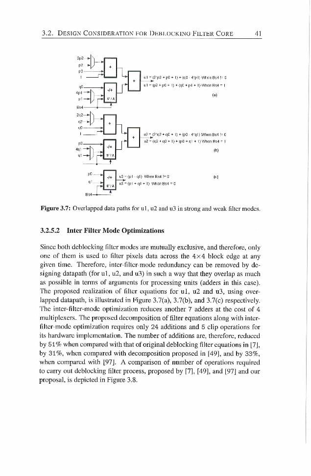
3.2. D E S I G N C O N S I D E R A T I O N FOR D E B L O C K I N G F I L T E R C O R E 41
2p2-
P 2 -
p O -
1
q C -
B54 2 q 2 - ^ '
q 2 - ^
q O -
-/+
S' / A
U l -
u l -
I
pc 4q1
Ml
-ƒ+ S'/A
u 2 -
u2 -
pC-
qi -1+ u3 -
S'/A u3 -
_ i
(b)
(c)
Figure 3.7: Overlapped data paths for u l , u2 and u3 in strong and weak fiher modes.
3.2.5.2 Inter Filter Mode Optimizations
Since both deblocking filter modes are mutually exclusive, and therefore, only
one of them is used to filter pixels data across the 4 x 4 block edge at any
given time. Therefore, inter-filter-mode redundancy can be removed by de
signing datapath (for u l , u2, and u3) in such a way that they overlap as much
as possible in terms of arguments for processing units (adders in this case).
The proposed reahzadon of fiher equadons for u l , u2 and u3, using over
lapped datapath, is illustrated in Figure 3.7(a), 3.7(b), and 3.7(c) respectively.
The inter-filter-mode optimization reduces another 7 adders at the cost of 4
multiplexers. The proposed decomposition of filter equadons along with inter-
filter-mode optimizadon requires only 24 additions and 5 clip operations for
its hardware implementation. The number of additions are, therefore, reduced
by 5 1 % when compared with that of original deblocking filter equadons in [7],
by 3 1 % , when compared with decomposition proposed in [49], and by 33%,
when compared with [97]. A comparison of number of operations required
to carry out deblocking filter process, proposed by [7], [49], and [97] and our
proposal, is depicted in Figure 3.8.
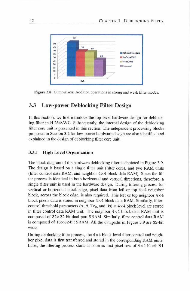
42 C H A P T E R 3. D E B L O C K I N G F I L T E R
• HlHAVCSanditd
Vi'ebb200a
H PropoMd
Ref.
Figure 3.8: Comparison: Addition operations in strong and weak filter modes.
3.3 Low-power Deblocking Filter Design
In this section, we first introduce the top-level hardware design for deblock
ing filter in H.264/AVC. Subsequently, the internal design of the deblocking
fiher core unit is presented in this section. The independent processing blocks
proposed in Secdon 3.2 for low-power hardware design are also idendfied and
explained in the design of deblocking filter core unit.
3.3.1 High Level Organization
The block diagram of the hardware deblocking filter is depicted in Figure 3.9.
The design is based on a single filter unit (filter core), and two R A M units
(filter control data R A M , and neighbor 4 x 4 block data R A M ) . Since the fil
ter process is identical in both horizontal and vertical directions, therefore, a
single filter unit is used in the hardware design. During fihering process for
vertical or horizontal block edge, pixel data f rom left or top 4 x 4 neighbor
block, across the block edge, is also required. This left or top neighbor 4 x 4
block pixels data is stored in neighbor 4 x 4 block data R A M . Similarly, filter-
control-threshold parameters (a, (3, TCQ, and Bs) at 4 x 4 block level are stored
in filter control data R A M unit. The neighbor 4 x 4 block data R A M unit is
composed of 32 x 32-bit dual port SRAM. Similarly, filter control data R A M
is composed of 16 x 32-bit SRAM. A l l the datapaths in Figure 3.9 are 32-bit
wide.
During deblocking filter process, the 4 x 4 block level filter control and neigh
bor pixel data is first transferred and stored in the corresponding R A M units.
Later, the filtering process stalls as soon as first pixel-row of 4 x 4 block B1
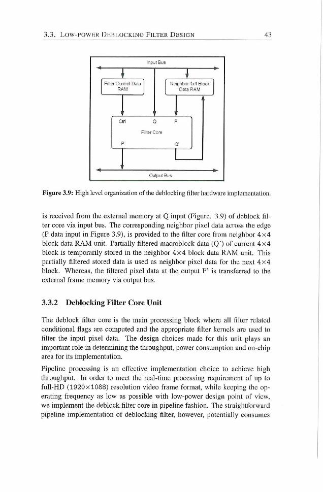
3.3. L O W - P O W E R D E B L O C K I N G F I L T E R D E S I G N 43
R 1er Ccfiircl DaQ N e i g h b o r 4:<:4 B I c c ' :
Dm R. i .M
:::tr1 O P
Fl terCo-B
P Q'
Output E „s
Figure 3.9: High level organization of the deblocking filter hardware implementation.
is received f rom the extemal memory at Q input (Figure. 3.9) of deblock fil
ter core via input bus. The corresponding neighbor pixel data across the edge
(P data input in Figure 3.9), is provided to the filter core f rom neighbor 4 x 4
block data R A M unit. Pardally filtered macroblock data (QO of cuiTent 4 x 4
block is temporarily stored in the neighbor 4 x 4 block data R A M unit. This
partially filtered stored data is used as neighbor pixel data for the next 4 x 4
block. Whereas, the filtered pixel data at the output P' is transferred to the
extemal frame memory via output bus.
3.3.2 Deblocking Filter Core Unit
The deblock filter core is the main processing block where all fiher related
condidonal flags are computed and the appropriate filter kemels are used to
filter the input pixel data. The design choices made for this unit plays an
important role in determining the throughput, power consumption and on-chip
area for its implementation.
Pipehne processing is an effective implementation choice to achieve high
throughput. In order to meet the real-time processing requirement of up to
fuU-HD (1920x1088) resolution video frame format, while keeping the op
erating frequency as low as possible with low-power design point of view,
we implement the deblock fiher core in pipeline fashion. The straightforward
pipeline implementadon of deblocking filter, however, potentially consumes
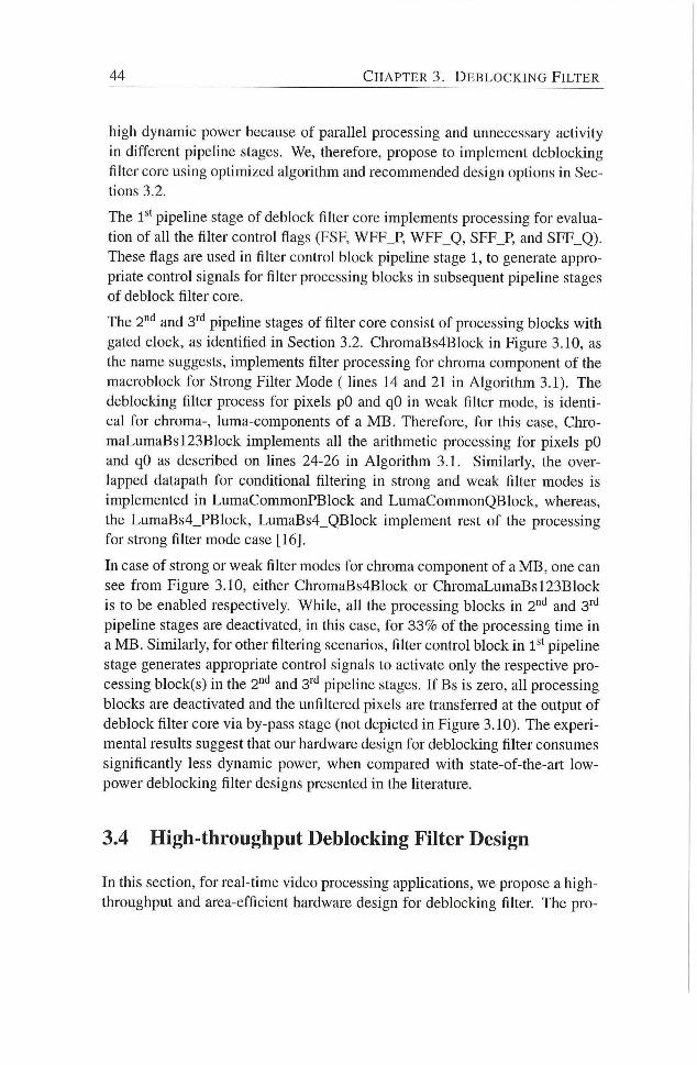
44 C H A P T E R 3. D E B L O C K I N G F I L T E R
high dynamic power because of parallel processing and unnecessary activity
in different pipehne stages. We, therefore, propose to implement deblocking
filter core using optimized algorithm and recommended design options in Sec
tions 3.2.
The 1**' pipeline stage of deblock filter core implements processing for evalua
tion of ah the filter control flags (FSF, WFF_P, WFF_Q, SFF_P, and SFF_Q).
These flags are used in filter control block pipehne stage 1, to generate appro
priate control signals for filter processing blocks in subsequent pipeline stages
of deblock filter core.
The 2"'' and 3" pipeline stages of filter core consist of processing blocks wi th
gated clock, as identified in Section 3.2. ChromaBs4Block in Figure 3.10, as
the name suggests, implements filter processing for chroma component of the
macroblock for Strong Filter Mode ( hnes 14 and 21 in Algori thm 3.1). The
deblocking fiker process for pixels pO and qO in weak filter mode, is identi
cal for chroma-, luma-components of a M B . Therefore, for this case, Chro-
maLumaBsl23Block implements ah the arithmetic processing for pixels pO
and qO as described on lines 24-26 in Algorithm 3.1. Similarly, the over
lapped datapath for conditional filtering in strong and weak filter modes is
implemented in LumaCommonPBlock and LumaCommonQBlock, whereas,
the LumaBs4_PBlock, LumaBs4_QBlock implement rest of the processing
for strong filter mode case [16].
In case of strong or weak filter modes for chroma component of a M B , one can
see f rom Figure 3.10, either ChromaBs4Block or ChromaLumaBsl23Block
is to be enabled respectively. While, all the processing blocks in 2"* and 3''''
pipehne stages are deactivated, in this case, for 33% of the processing time in
a M B . Similarly, for other filtering scenarios, filter control block in 1**' pipeline
stage generates appropriate control signals to activate only the respective pro
cessing block(s) in the 2"'' and 3''' pipeline stages. I f Bs is zero, afl processing
blocks are deactivated and the unfiltered pixels are transferred at the output of
deblock filter core via by-pass stage (not depicted in Figure 3.10). The experi
mental results suggest that our hardware design for deblocking filter consumes
significantly less dynamic power, when compared with state-of-the-art low-
power deblocking filter designs presented in the literamre.
3.4 High-throughput Debloclting Filter Design
In this section, for real-time video processing apphcations, we propose a high-
throughput and area-efficient hardware design for deblocking filter. The pro-
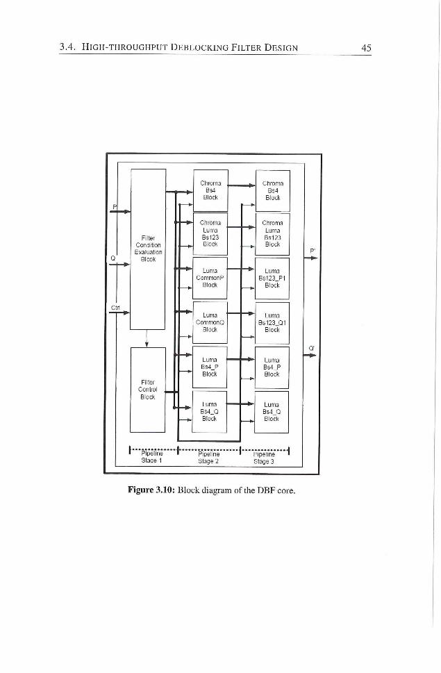
H I G H - T H R O U G H P U T D E B L O C K I N G F I L T E R D E S I G N
Fi l ter
C o n ( j i t o n
Eva lua t ion
BIcok
Ctrl
Fi l ter
Contro l
B lock
C h r o m a
Bs4
B lock
C h r o m a
Lun\3
B3123
B lock
L u m a
C o m n x j n F
B lock
Luma
C o m n x i n Q
Block
Luma
Gs4_P
Block
Luma
B s 4 _ Q
Block
P ipe l i ne
Stage 1 P ipe l ine
S tage 2
^ ' p loe l i ne
C h r o m a
B s 4
B lock
Ch roma
L u m a
8-3123
B lock
L u m a
B s 1 2 3 _ P 1
B lock
L u m a
B s 1 2 3 _ Q 1
B lock
L u m a
B s 4 _ P
B lock
L u m a
Bs4_Q
BlocJ(
P ipe l i ne
Stage 3
Figure 3.10: Block diagram of the DBF core.
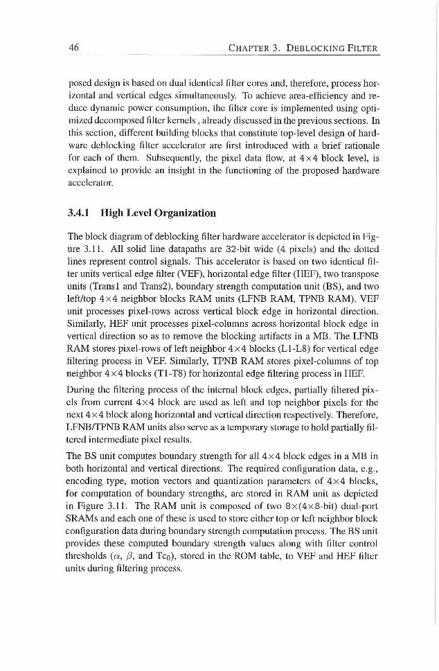
46 C H A P T E R S . D E B L O C K I N G F I L T E R
posed design is based on dual identical filter cores and, therefore, process hor
izontal and vertical edges simultaneously. To achieve area-efficiency and re
duce dynamic power consumption, the fiher core is implemented using opti
mized decomposed filter kernels , already discussed in the previous sections. In
this section, different building blocks that constitute top-level design of hard
ware deblocking filter accelerator are first introduced with a brief rationale
for each of them. Subsequently, the pixel data flow, at 4 x 4 block level, is
explained to provide an insight in the functioning of the proposed hardware
accelerator.
3.4.1 High Level Organization
The block diagram of deblocking filter hardware accelerator is depicted in Fig
ure 3.11. A l l solid line datapaths are 32-bit wide (4 pixels) and the dotted
lines represent control signals. This accelerator is based on two identical fil
ter units vertical edge filter (VEF), horizontal edge filter (HEF), two transpose
units (Trans 1 and Trans2), boundary strength computation unit (BS), and two
left/top 4 x 4 neighbor blocks R A M units (LENB R A M , TPNB R A M ) . VEF
unit processes pixel-rows across vertical block edge in horizontal direction.
Similarly, HEF unit processes pixel-columns across horizontal block edge in
vertical direction so as to remove the blocking artifacts in a M B . The LENB
R A M stores pixel-rows of left neighbor 4 x 4 blocks (L1-L8) for vertical edge
filtering process in VEF. Similarly, TPNB R A M stores pixel-columns of top
neighbor 4 x 4 blocks (T1-T8) for horizontal edge filtering process in HER
During the filtering process of the intemal block edges, partially filtered pix
els f rom current 4 x 4 block are used as left and top neighbor pixels for the
next 4 x 4 block along horizontal and vertical direction respectively. Therefore,
LFNB/TPNB R A M units also serve as a temporary storage to hold partially fil
tered intermediate pixel results.
The BS unit computes boundary strength for all 4 x 4 block edges in a M B in
both horizontal and vertical directions. The required configuration data, e.g.,
encoding type, motion vectors and quantization parameters of 4 x 4 blocks,
for computation of boundary strengths, are stored in R A M unit as depicted
in Figure 3.11. The R A M umt is composed of two 8 x (4x 8-bit) dual-port
SRAMs and each one of these is used to store either top or left neighbor block
configuration data during boundary strength computation process. The BS unit
provides these computed boundary strength values along with filter control
thresholds (a, /3, and TCQ), stored in the R O M table, to VEF and HEF filter
units during filtering process.
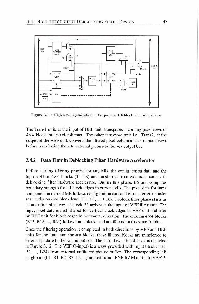
3.4. H I G H - T H R O U G H P U T D E B L O C K I N G F I L T E R D E S I G N 47
bus •Jegico lop
I ='31 Co-
HEF Q FP \
I l / i j i : 5
I
Figure 3.11: High level organization of the proposed deblock filter accelerator
The Trans 1 unit, at the input of HEF unit, transposes incoming pixel-rows of
4 x 4 block into pixel-columns. The other transpose umt i.e. Trans2, at the
output of the HEF unit, converts the filtered pixel-columns back to pixel-rows
before transferring them to external picture buffer via output bus.
3.4.2 Data Flow in Deblocking Filter Hardware Accelerator
Before stardng filtering process for any M B , the configuradon data and the
top neighbor 4 x 4 blocks (T1-T8) are transferred f rom external memory to
deblocking filter hardware accelerator. During this phase, BS unit computes
boundary strength for all block edges in current M B . The pixel data for luma
component in cuiTcnt M B follows configuration data and is transferred in raster
scan order on 4x4 block level ( B l , B2, B16). Deblock filter phase starts as
soon as first pixel-row of block B l arrives at the input of VEF filter unit. The
input pixel data is first filtered for vertical block edges in VEF unit and later
by HEF unit for block edges in horizontal direcdon. The chroma 4 x 4 blocks
(B17, BIS , B24) fol low luma blocks and are filtered in the same fashion.
Once the filtering operation is completed in both directions by VEF and HEF
units for the luma and chroma blocks, these filtered blocks are transferred to
external picture buffer via output bus. The data-flow at block level is depicted
in Figure 3.12. The VEF(Q-input) is always provided with input blocks ( B l ,
B2, B24) f r o m external unfiltered picture buffer. The corresponding left
neighbors ( L l , B l , B2, B3, L2 , . . . ) are fed f rom LFNB R A M unit into VEF(P-
48 C H A P T E R S . D E B L O C K I N G F I L T E R
input) filter unit.
The partially filtered blocks (B1, B 2 , B 2 4 ) f rom V E F (Q-output) are always
stored in LFNB R A M and are used as left neighbor blocks in next filter block
cycle. The filtered blocks ( B l , B2, B23), after completion of vertical edge
filtering operation f rom VEF unit, are transfeiTcd to next filtering unit HEF
for horizontal edge filtering operation. The last 4 x 4 block in each block row
of current M B (B4, B8, B12) are temporarily stored in the LFNB R A M , and
are also sent to HEF umt via the same data path before start of next block
row. HEF unk also receives 4 x 4 blocks of current M B , after being filtered
in horizontal direction by VEF unit, in the same sequence as that of V E F unit
(Q-input), as shown in Figure 3.12.
The last column of 4 x 4 blocks (B4, B8, B12, B16, B18, B20, B22 and B24)
in current M B are stored in LFNB R A M as (L1-L8) for next macroblock after
compledon of filter operadon in both directions. The blocks in the last luma,
chroma block rows (B13, B14, B15, B17, B19, B21 and B23), temporarily
stored in the TPNB R A M module are sent to the external picUire buffer. These
blocks are transposed f rom pixel-columns to pixel-rows orientadon during the
transfer process by Trans2 unit. The left neighbor blocks of the previous M B
are directly sent f rom LFNB R A M .
When vertical filtering process for current M B is completed, transfer of config
uradon data and top neighbor blocks (T1-T8) in next M B is inidated, in parallel
wi th the processing of HEF unit for cuiTent M B , to maximize the throughput
of the deblock filter
3.4.3 Transpose Unit in Deblocking Filter Hardware Accelerator
Our deblocking fiher hardware accelerator utihzes two identical filter units to
achieve high throughput. However, because of identical filter units, two trans
pose unks are required in the design as depicted in Figure 3.11. These trans
pose units are an overhead of such an arrangement and cost significant amount
of area for their implementation. Different techniques have been presented in
the literature to reduce area cost of transpose units. A l l of these techniques, in
one way or another, require a separate temporal register file for its realization.
We, however, fol low a different approach in our design to minimize this over
head. We identify that the transpose process and the boundary strength compu
tation process are two mutually exclusive set of operations in time. The storage
used for BS parameters is a free resource during the transpose phase. There
fore, in our design we re-use R A M units s as a storage during the transpose
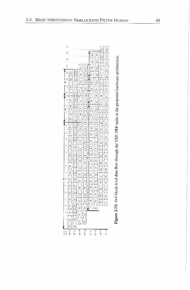
3.4. H I G H - T H R O U G H P U T D E B L O C K I N G F I L T E R D E S I G N 49
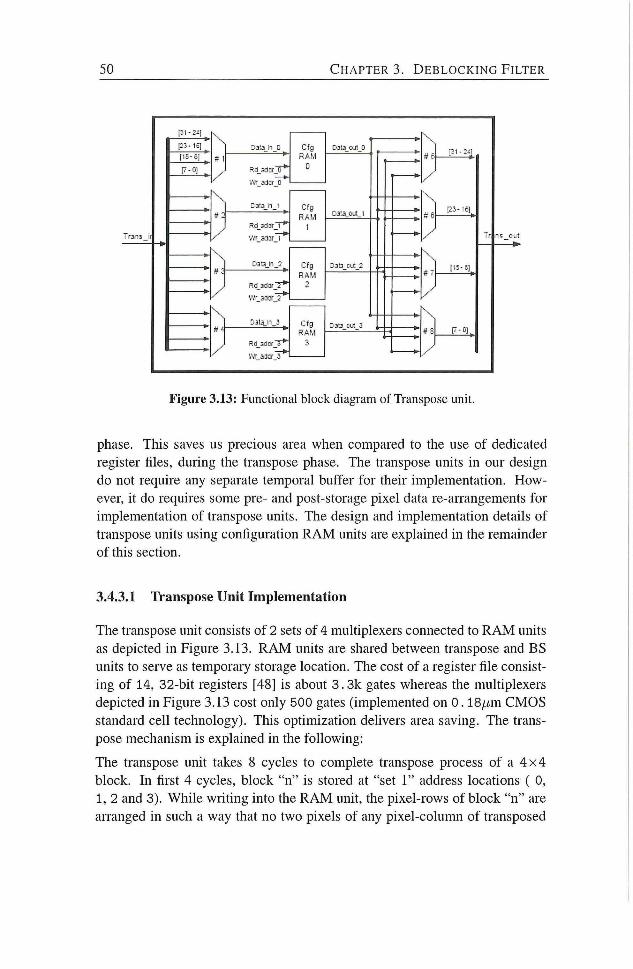
50 C H A P T E R 3. D E B L O C K I N G F I L T E R
12-3-15]
1'
• K
4 \
najii-jy
VV 33:rT*
Cfg RAM
D
Cfg RAM
1
Cfg RAM
Cfg RAM
' ir 5 -
-/
• \
' # 6¬
' * ' -
• \
! * - -
l i 5 - . ; i
Figure 3.13: Functional block diagram of Transpose unit.
phase. This saves us precious area when compared to the use of dedicated
register files, during the transpose phase. The transpose units in our design
do not require any separate temporal buffer for their implementation. How
ever, it do requires some pre- and post-storage pixel data re-aiTangements for
implementation of transpose units. The design and implementation details of
transpose units using configuration R A M units are explained in the remainder
of this section.
3.4.3.1 Transpose Unit Implementation
The transpose unit consists of 2 sets of 4 multiplexers connected to R A M units
as depicted in Figure 3.13. R A M units are shared between transpose and B S
units to serve as temporary storage location. The cost of a register file consist
ing of 14, 32-bit registers [48] is about 3. 3k gates whereas the multiplexers
depicted in Figure 3.13 cost only 500 gates (implemented on 0 .18pm C M O S
standard cell technology). This optimization delivers area saving. The trans
pose mechanism is explained in the following:
The transpose unit takes 8 cycles to complete transpose process of a 4 x 4
block. In first 4 cycles, block "n" is stored at "set 1" address locations ( 0,
1, 2 and 3). While wridng into the R A M unit, the pixel-rows of block " n " are
arranged in such a way that no two pixels of any pixel-column of transposed
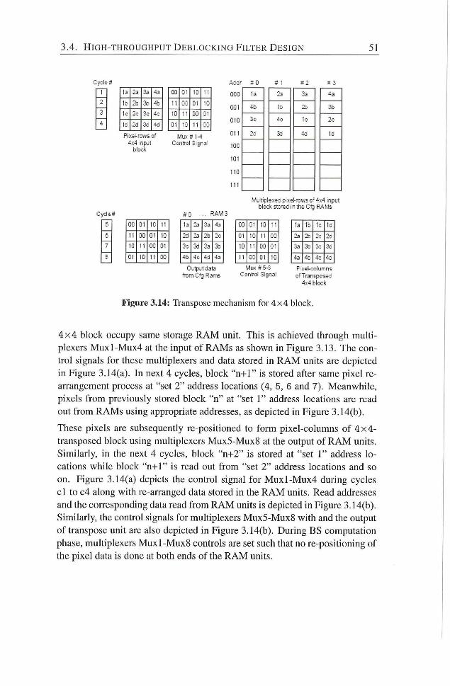
3.4. H I G H - T H R O U G H P U T D E B L O C K I N G F I L T E R D E S I G N 51
# 0
I:- - 3
1- ; i :
-;:
1: 3d 4o
P i ï ï - Ü . V S of
block
03 2 • i j
l l 01 • -
Id OJ
Ci • - 11
Mux # 1 4
Ccnfrct -2
000
001
010
O i l
100
101
Id
I IC
Wu I i p k x ^ : z- xel- icws c" •ix4 input
block s t ; . - 5 d i " t f e C f 3 P J M , 1 s
CC 01 IC i -
I I Oü Cl i :
IC 11 cc 0-
Cl 10 11 o :
. . R A M 3
1.1 23 45
•14 J> 2b 2::
o-. ;. j :.;
- b - d 43
Outp.1 data
T i m C-13 Rams
CO : • 10 • •
o T ^ T T T T
MLI>: ff 5-B Cont ro Signal
la 1; 1 : 1 :
2a 2 : 2 :
;.: J.:
4a 4c. 4 : -: P xsl-'Dolumns
o f T r a n j p o s i - :
4 ï 4 bloc^fc
Figure 3.14: Transpose mechanism for 4x4 block.
4 x 4 block occupy same storage R A M unit. This is achieved through multi
plexers M u x l - M u x 4 at the input of RAMs as shown in Figure 3.13. The con
trol signals for these multiplexers and data stored in R A M units are depicted
in Figure 3.14(a). In next 4 cycles, block "n-i-1" is stored after same pixel re
arrangement process at "set 2" address locations (4, 5, 6 and 7). Meanwhile,
pixels f rom previously stored block "n" at "set I " address locations are read
out f rom RAMs using appropriate addresses, as depicted in Figure 3.14(b).
These pixels are subsequently re-positioned to form pixel-columns of 4 x 4 -
transposed block using multiplexers Mux5-Mux8 at the output of R A M units.
Similarly, in the next 4 cycles, block "n+2" is stored at "set 1" address lo
cations while block " n + 1 " is read out f rom "set 2" address locations and so
on. Figure 3.14(a) depicts the control signal for M u x l - M u x 4 during cycles
c l to c4 along with re-arranged data stored in the R A M unks. Read addresses
and the corresponding data read f rom R A M units is depicted in Figure 3.14(b).
Similarly, the control signals for multiplexers Mux5-Mux8 with and the output
of transpose umt are also depicted in Figure 3.14(b). During BS computation
phase, multiplexers M u x l - M u x 8 controls are set such that no re-positioning of
the pixel data is done at both ends of the R A M units.
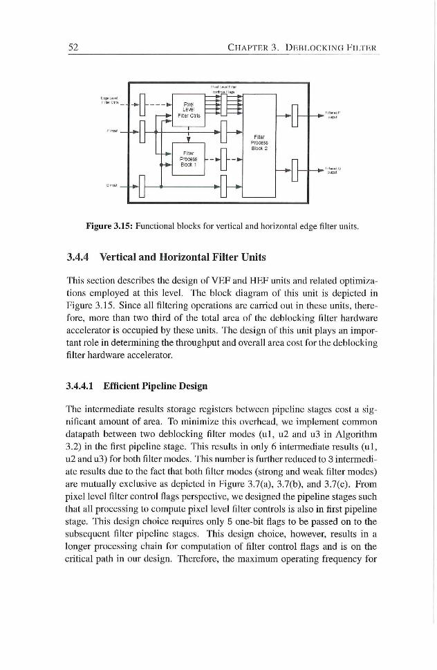
52 C H A P T E R 3. D E B L O C K I N G F I L T E R
Figure 3.15: Functional blocks for vertical and horizontal edge filter units.
3.4.4 Vertical and Horizontal Filter Units
This section describes the design of VEF and HEF units and related opdmiza
tions employed at this level. The block diagram of this unit is depicted in
Figure 3.15. Since all filtering operadons are carried out in these units, there
fore, more than two third of the total area of the deblocking filter hardware
accelerator is occupied by these units. The design of this unit plays an impor
tant role in determining the throughput and overall area cost for the deblocking
filter hardware accelerator.
3.4.4.1 Efficient Pipeline Design
The intermediate results storage registers between pipeline stages cost a sig
nificant amount of area. To minimize this overhead, we implement common
datapath between two deblocking filter modes ( u l , u2 and u3 in Algorithm
3.2) in the first pipeline stage. This results in only 6 intermediate results ( u l ,
u2 and u3) for both filter modes. This number is further reduced to 3 intermedi
ate results due to the fact that both filter modes (strong and weak filter modes)
are mutuahy exclusive as depicted in Figure 3.7(a), 3.7(b), and 3.7(c). From
pixel level filter control flags perspecdve, we designed the pipeline stages such
that all processing to compute pixel level filter controls is also in first pipehne
stage. This design choice requires only 5 one-bit flags to be passed on to the
subsequent filter pipehne stages. This design choice, however, results in a
longer processing chain for computation of filter control flags and is on the
critical path in our design. Therefore, the maximum operating frequency for
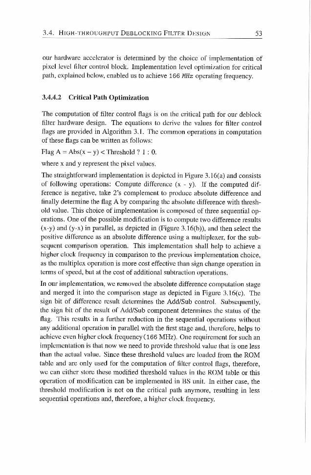
3 . 4 . H I G H - T H R O U G H P U T D E B L O C K I N G F I L T E R D E S I G N 5 3
our hardware accelerator is determined by the choice of implementation of
pixel level filter control block. Implementadon level opdmizadon for critical
path, explained below, enabled us to achieve 166 MHz operating frequency.
3.4.4.2 Critical Path Optimization
The computadon of filter control flags is on the cridcal path for our deblock
filter hardware design. The equations to derive the values for filter control
flags are provided in Algorithm 3 . 1 . The common operadons in computation
of these flags can be written as follows:
Flag A = Abs(x - y) < Threshold ? 1 : 0.
where x and y represent the pixel values.
The straightforward implementadon is depicted in Figure 3.16(a) and consists
of following operations: Compute difference (x - y). I f the computed dif
ference is negative, take 2's complement to produce absolute difference and
finally determine the flag A by comparing the absolute difference with thresh
old value. This choice of implementation is composed of three sequential op
eradons. One of the possible modificadon is to compute two difference results
(x-y) and (y-x) in parallel, as depicted in (Figure 3.16(b)), and then select the
positive difference as an absolute difference using a muldplexer, for the sub
sequent comparison operation. This implementadon shad help to achieve a
higher clock frequency in comparison to the previous implementation choice,
as the multiplex operation is more cost effective than sign change operation in
terms of speed, but at the cost of additional subtraction operations.
In our implementation, we removed the absolute difference computation stage
and merged it into the comparison stage as depicted in Figure 3.16(c). The
sign bit of difference result determines the Add/Sub control. Subsequentiy,
the sign bit of the result of Add/Sub component determines the status of the
flag. This results in a further reduction in the sequential operations without
any additional operation in parallel with the first stage and, therefore, helps to
achieve even higher clock frequency (166 MHz) . One requirement for such an
implementation is that now we need to provide threshold value that is one less
than the actual value. Since these threshold values are loaded f rom the R O M
table and are only used for the computation of filter control flags, therefore,
we can either store these modified threshold values in the R O M table or this
operation of modification can be implemented in BS unit. In either case, the
threshold modification is not on the critical path anymore, resulting in less
sequential operations and, therefore, a higher clock frequency.
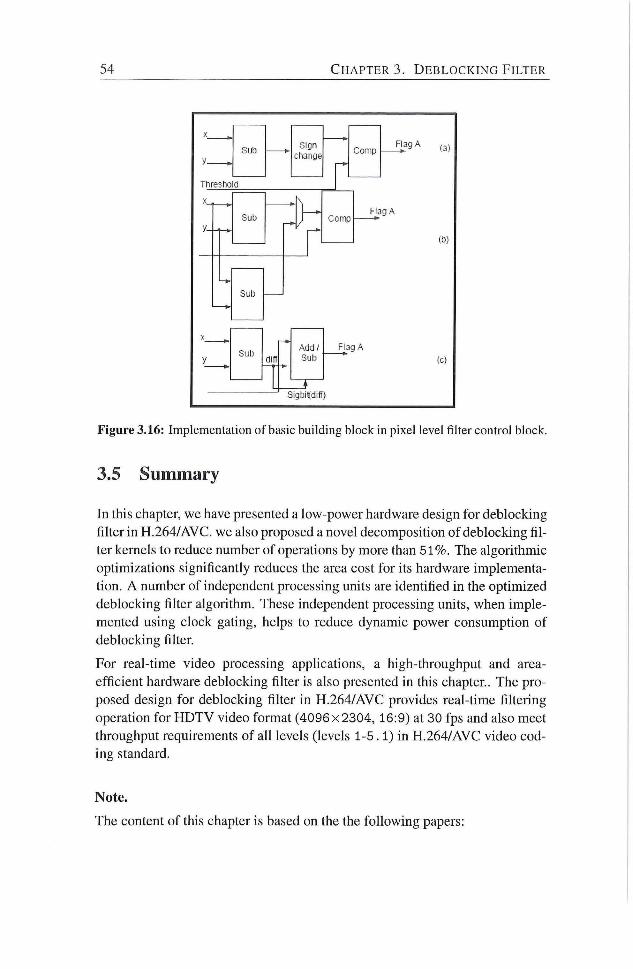
54 C H A P T E R 3. D E B L O C K I N G F I L T E R
S u b S i g n
c l range C o m p
F lag A S u b
S i g n
c l range
r
C o m p F lag A
S u b S i g n
c l range
r
C o m p
T h r e s h o l d
X
Sub
ni
C o m p F aa A
;ul : i Oin
A d d /
S u b
F lag A
(c)
Sigbit t 'd i f f )
Figure 3.16: Implementation of basic building block in pixel level filter control block.
3.5 Summary
In this chapter, we have presented a low-power hardware design for deblocking
fiher in H.264/AVC. we also proposed a novel decomposidon of deblocking fil
ter kernels to reduce number of operadons by more than 5 1 % . The algorithmic
optimizadons significantly reduces the area cost for its hardware implementa
tion. A number of independent processing units are idendfied in the optimized
deblocking filter algorithm. These independent processing units, when imple
mented using clock gadng, helps to reduce dynamic power consumpdon of
deblocking filter.
For real-time video processing apphcations, a high-throughput and area-
efficient hardware deblocking filter is also presented in this chapter.. The pro
posed design for deblocking filter in H.264/AVC provides real-time filtering
operadon for H D T V video format (4096x2304, 16:9) at 30 fps and also meet
throughput requirements of all levels (levels 1-5.1) in H.264/AVC video cod
ing standard.
Note.
The content of this chapter is based on the the fol lowing papers:

3.5. S U M M A R Y 55
Muhammad Nadeem, Stephan Wong, Georgi Kuzmanov and Ahsan Shab
bir, A High-throughput, Area-efficient Hardware Accelerator for Adaptive De
blocking Filter in H.264/AVC, proceedings of International Symposium on
Embedded Systems For Real-dme Multimedia 2009 (ESTIMEDIA), pp. 18¬
27, Grenoble, France, October 2009.
Muhammad Nadeem, Stephan Wong, Georgi Kuzmanov, Ahsan Shabbir,
M.F. Nadeem and Fakhar Anjam, Low-power, High-throughput Deblocking
Filter for H.264/AVC, proceedings of Internadonal Symposium on System-on-
Chip 2010 (SoC), pp. 93-98, Tampere, Finland, September 2010.

4 Intra Prediction
THE H.264/AVC video coding standard supports multiple directional intra
prediction modes to reduce the spatial redundancy in the video signal.
There 4 intra prediction modes for luma 16x 16 block type, 4 intra predicdon
modes for chroma 8 x 8 block type, and 9 intra predicdon modes for 4 x 4 block
type in H.264/AVC. These muldple intra predicdon modes help to significandy
improve the encoding performance of intra-frame encoder. Studies have shown
that H.264/AVC outperforms JPEG2000, a state-of-the-art stdl-image coding
standard, in terms of subjective as well as objective image quahty [66]. This
makes H.264/AVC intra-frame codec an attractive choice to be utihzed as an
image compression engine. Applicadons like Digkal Sdh Camera (DSC) em
ploy intra-frame encoding technique to compress high-resoludon images.
In a video frame encoded in intra mode, the current macroblock is predicted
f rom previously encoded neighboring macroblocks f rom the same video frame.
A video frame with all MBs encoded in intra mode does not depend on any
other video frame(s) and, therefore, can be decoded independently. Con
sequently, a video encoded with intra-frames only, is easier to edit than a
video encoded with inter-frames (frames predicted f rom past or future video
frames). Similarly, in many surveihance systems, video is compressed using
intra-frames encoding mode due to legal reasons. Courts in many countries
do not accept predicted frames as legal evidence [98]. As a resuk, a typical
video surveillance system compresses videos using intra-encoded frames only.
Consequently, intra-only video coding is widely used coding technique in tele
vision studio broadcast, digital cinema and surveihance video apphcadons.
The H.264/AVC comphant baseline decoder is approximately 2 .5 dmes more
time-complex than H.263 compliant basehne-decoder [66]. According to anal
ysis of run-time profiling data of H.264/AVC baseline decoder sub-funcdons,
intra-predicdon is one of the top 3 compute-intensive functions [66]. A high-
57
58 C H A P T E R 4. I N T R A P R E D I C T I O N
throughput intra-frame processing chain is, therefore, an important require
ment for H.264/AVC intra-frame codec for real-time video processing appli
cations. The demanding characteristics of intra-prediction algorithm suggest
its hardware implementation for high-definition video applications, where even
larger frame size at higher frame rates are to be processed in real-time.
In this chapter, we describe a high-throughput and area-efficient design for
intra-prediction umt in H.264/AVC compliant video codecs. The main contri
butions are as follows:
1. A proposal to optimize the intra-prediction algorithm for 4 x 4 luma
blocks by decomposing the filter kernels. The proposed decomposition
significantly reduces additions operations for its hardware implementa
tion (27% - 60% reduction).
2. A n efficient hardware design of intra-prediction unit to reduce on-chip
area by using hardware sharing approach for mutually exclusive pro
cessing scenarios (approximately 21K gates).
Furthermore, we also optimize the common equations in intra-prediction al
gorithm, to efficiently compute intra-predicted samples for 16x16 luma and
8 x 8 chroma blocks.
The chapter is organized as follows. Section 4.1 provides an overview of intra
prediction algorithm and also describes proposed optimizadons in the algo
rithm. The proposed configurable hardware design is presented in Section 4.2,
whereas, Secdon 4.3 summarizes this chapter.
4.1 Intra Prediction Algorithm
In this section, we briefly introduce intra-frame processing chain in
H.264/AVC video decoder Subsequently, an overview of intra prediction al
gorithm for 4 x 4 luma blocks, 16x16 luma blocks, and 8 x 8 chroma blocks is
provided in separate subsections. The optimizadons to reduce number of oper
ations in intra prediction algorithm are also explained along with the algorithm
overview.
The functional block diagram for an H.264/AVC intra-frame decoder is de
picted in Figure 4.1. The entropy decoder unit parses input bitstream and de
codes intra-predicdon mode used for cuiTcnt M B . This intra-prediction mode
information is then passed on to intra prediction unit to generate the intra-
predicted pixels block as per given intra-prediction mode.
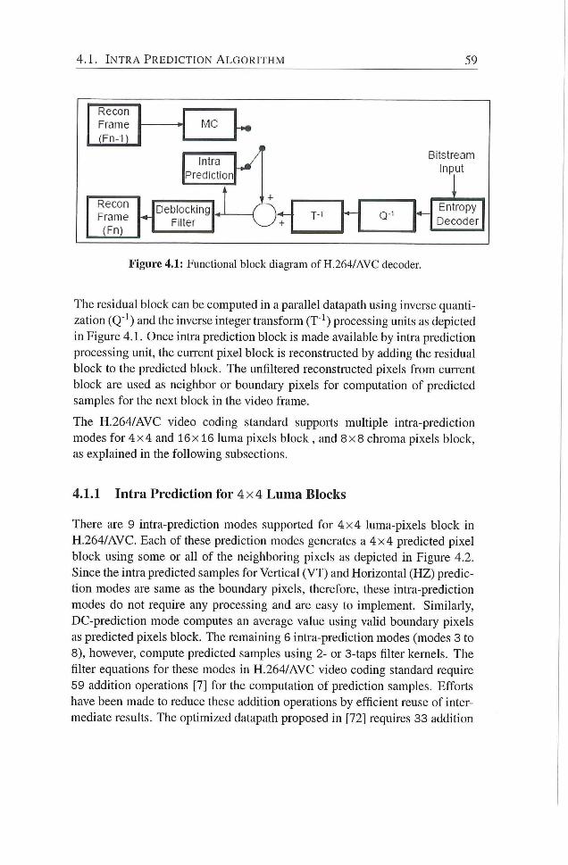
4 . 1 . I N T R A P R E D I C T I O N A L G O R I T H M 59
Recon
Frame
(Fn-1)
-A MC
Intra
Prediction
Recon Frame
Detilocl<ing
Filter
Bitstream Input
Or T-1 Q-' Entropy
T-1 Q-' Decoder
Figure 4.1: Functional block diagram of H.264/AVC decoder
The residual block can be computed in a parallel datapath using inverse quanti
zation (Q'^) and the inverse integer transfonn (T"^) processing units as depicted
in Figure 4.1. Once intra predicdon block is made available by intra prediction
processing unit, the cunent pixel block is reconstructed by adding the residual
block to the predicted block. The unfiltered reconstructed pixels f rom cuiTcnt
block are used as neighbor or boundary pixels for computation of predicted
samples for the next block in the video frame.
The H.264/AVC video coding standard supports multiple intra-prediction
modes for 4 x 4 and 16x16 luma pixels block , and 8 x 8 chroma pixels block,
as explained in the following subsections.
4.1.1 Intra Prediction for 4 x 4 Luma Blocks
There are 9 intra-prediction modes supported for 4 x 4 luma-pixels block in
H.264/AVC. Each of these predicdon modes generates a 4 x 4 predicted pixel
block using some or all of the neighboring pixels as depicted in Figure 4.2.
Since the intra predicted samples for Vertical (VT) and Horizontal (HZ) predic
tion modes are same as the boundary pixels, therefore, these intra-prediction
modes do not require any processing and are easy to implement. Similarly,
DC-prediction mode computes an average value using vahd boundary pixels
as predicted pixels block. The remaining 6 intra-prediction modes (modes 3 to
8), however, compute predicted samples using 2- or 3-taps filter kernels. The
filter equations for these modes in H.264/AVC video coding standard require
59 addition operations [7] for the computation of prediction samples. Efforts
have been made to reduce these addition operations by efficient reuse of inter
mediate results. The optimized datapath proposed in [72] requires 33 addition
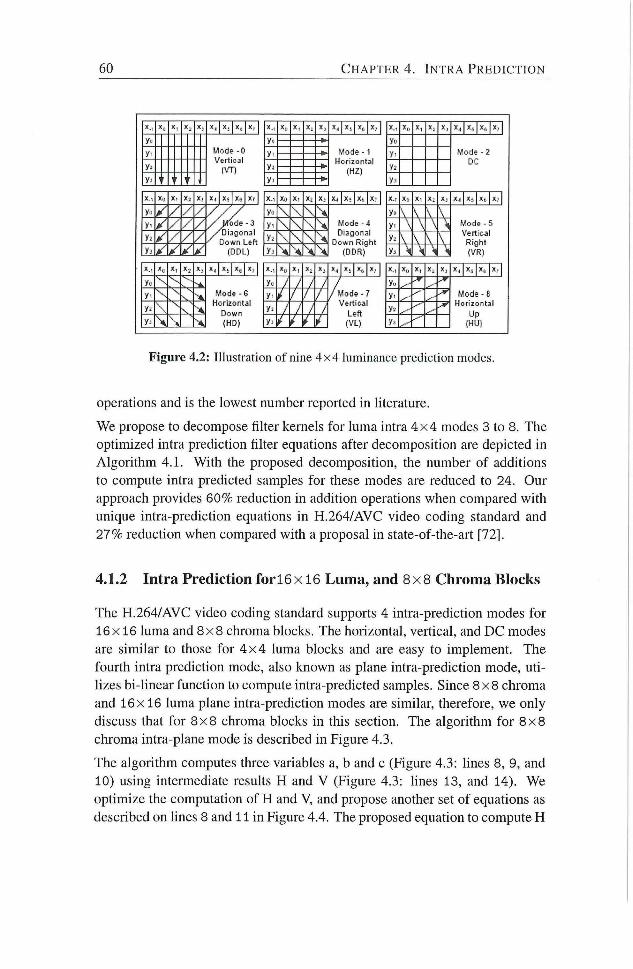
60 C H A P T E R 4. I N T R A P R E D I C T I O N
X. . >:. X . x J x^ 1 X , 1 X.- X . X , 1 X ; 1 Xt, | X ; 1 X . . x„ X, X , X^ 1 X^ 1 X[, |x,. 1
Mode - 0
Ver t i ca l
>••-
M o d e - 1
Hor i zon ta l
(HZ)
V o d e - 2
DC y- Mode - 0
Ver t i ca l y M o d e - 1
Hor i zon ta l
(HZ)
V o d e - 2
DC
Mode - 0
Ver t i ca l j ' i —&^
M o d e - 1
Hor i zon ta l
(HZ) y .
V o d e - 2
DC
Mode - 0
Ver t i ca l j ' i
M o d e - 1
Hor i zon ta l
(HZ) y .
V o d e - 2
DC
y j ?
Mode - 0
Ver t i ca l M o d e - 1
Hor i zon ta l
(HZ)
y-
V o d e - 2
DC
X.-, y.- X . x , J Xï 1 X.] 1 Xr 1 Xn X ' X . X 4 | x t | x t [ x . ' 1 X.- Xu Xl X; X i 1 X , 1 x>. 1 x.< 1 yu / / / . / /
y!ode - 3 Diagona l
Down Le f t
(DDL)
\ \ M o d e - 4 D iagona l
D o w n R igh t (DDR)
\ \ \ M o d e - 5
Ver t i ca l
R igh t
(VR)
y- / / / . / /
y!ode - 3 Diagona l
Down Le f t
(DDL)
\ \ M o d e - 4 D iagona l
D o w n R igh t (DDR)
\ \ \ M o d e - 5
Ver t i ca l
R igh t
(VR)
y^ / /
/ . / /
y!ode - 3 Diagona l
Down Le f t
(DDL)
Ï : \ M o d e - 4 D iagona l
D o w n R igh t (DDR)
\ \ \ \ M o d e - 5
Ver t i ca l
R igh t
(VR) y j /
/ . / /
y!ode - 3 Diagona l
Down Le f t
(DDL) i- \ • \ \
M o d e - 4 D iagona l
D o w n R igh t (DDR) \ M \
M o d e - 5
Ver t i ca l
R igh t
(VR)
. / /
y!ode - 3 Diagona l
Down Le f t
(DDL)
M o d e - 4 D iagona l
D o w n R igh t (DDR)
M o d e - 5
Ver t i ca l
R igh t
(VR)
X . , X . >!( 1 X l 1 x^ 1 Xf 1 X . . Xfi X- X j x^ 1 X l 1 Xt, 1X,. 1 X. . X j X 4 | X i | X t | l . . |
y j •-- ~ - -* M o d e - 6
Hor i zon ta l
D o w n
(HD)
y.. / / / / / M o d e - ?
Ve r t i ca l
Lef t
(VL)
Vlr ..- . - f
Mode - 8
H o r i z o n t a l
Up
(HU(
y- \ ••• •-*,
M o d e - 6
Hor i zon ta l
D o w n
(HD)
/ / / / / M o d e - ?
Ve r t i ca l
Lef t
(VL)
. - r Mode - 8
H o r i z o n t a l
Up
(HU(
\ ••
-••
M o d e - 6
Hor i zon ta l
D o w n
(HD)
/ / / / / M o d e - ?
Ve r t i ca l
Lef t
(VL)
Mode - 8
H o r i z o n t a l
Up
(HU( Y' \ ••
M o d e - 6
Hor i zon ta l
D o w n
(HD) /
/ M o d e - ?
Ve r t i ca l
Lef t
(VL) •"•*
Mode - 8
H o r i z o n t a l
Up
(HU(
Figure 4.2: Illustration of nine 4x4 luminance prediction modes.
operations and is the lowest number reported in literature.
We propose to decompose filter kernels for luma intra 4 x 4 modes 3 to 8. The
optimized intra prediction filter equations after decomposition are depicted in
Algori thm 4.1. With the proposed decomposition, the number of additions
to compute intra predicted samples for these modes are reduced to 24. Our
approach provides 60% reduction in addition operadons when compared with
unique intra-predicdon equadons in H.264/AVC video coding standard and
27% reduction when compared with a proposal in state-of-the-ait [72].
4.1.2 Intra Prediction for 16 x 16 Luma, and 8 x 8 Chroma Blocks
The H.264/AVC video coding standard supports 4 intra-predicdon modes for
16x 16 luma and 8 x 8 chroma blocks. The horizontal, verdcal, and DC modes
are similar to those for 4 x 4 luma blocks and are easy to implement. The
fourth intra prediction mode, also known as plane intra-predicdon mode, ut i
lizes bi-linear function to compute intra-predicted samples. Since 8 x 8 chroma
and 16x 16 luma plane intra-prediction modes are similar, therefore, we only
discuss that for 8 x 8 chroma blocks in this secdon. The algorithm for 8 x 8
chroma intra-plane mode is described in Figure 4.3.
The algorithm computes three variables a, b and c (Figure 4.3: lines 8, 9, and
10) using inteiiTiediate results H and V (Figure 4.3: lines 13, and 14). We
optimize the computation of H and V, and propose another set of equations as
described on lines 8 and 11 in Figure 4.4. The proposed equadon to compute H
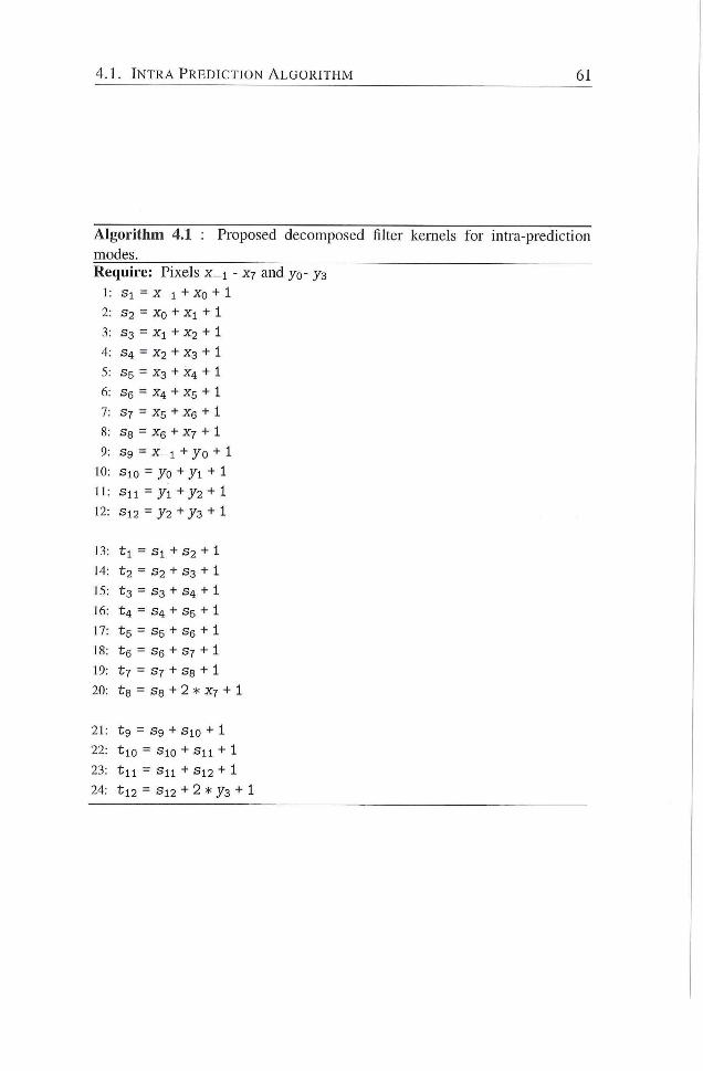
4 . 1 . I N T R A P R E D I C T I O N A L G O R I T H M 61
Algorithm 4.1 : Proposed decomposed filter kernels for intra-prediction
modes. Require: Pixels x_i - xj and yo- 73
1: Sl = X_ i + X o + 1
2: S2 = Xo + + 1
3: S3 = Xl + X 2 + 1
4: S 4 = X2 + X3 + 1
5: S5 = X 3 + X 4 + 1
6: S6 = X 4 + X 5 + 1
7: S7 = X 5 + X 6 + 1
8: S s = X e + X 7 + 1
9: sg = x_i +70 + 1
10: SlO = = 70 + 71 + 1
I I : S n = = 71+72 + 1 12: Sl2 = = 72 + 73 + 1
13: t l = Sl + S2 + 1
14: t 2 = S 2 + S3 + 1
15: t 3 = S3 + S 4 + 1
16: t 4 = S 4 + S5 + 1
17: t 5 = S5 + Se + 1
18: te = Se + S7 + 1
19: tl = S7 + S s + 1
20: ts = S s + 2 * X 7 + 1
21: tg = = Sg + Sio + 1 22: tio = Sio + Sn + 1
23: t i l = S n + S 1 2 + 1
24: t l 2 = S 1 2 + 2 * 73 + 1
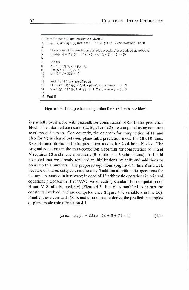
62 C H A P T E R 4. I N T R A P R E D I C T I O N
1. Intra Chroma Plane Prediction Mo(Je-3 2. If {p[x. -1] andpl-1. yJ with x = 0..7 and. y--1 ..7 are available) Then 3. 4. The values ofthe prediction samples predjx.y] are denved as follows: 5. predjx.y] = Clip (a + b ' ix - 3} + C (y - 3) + 16 » 5)
12. and H and V are specified as 13. H = I (>:• +1 ) ' (p[4+x', -1] - p[2-x'. -1], where x' = 0 .. 3 14. V = z (y- +1) ' {p[-i, 4+y'] - p[-1, 2-y'], where y' = 0 .. 3 15. 16. End If
Figure 4.3: Intra-prediction algorithm for 8x8 luminance block.
is partially overlapped with datapath for computation of 4 x 4 intra-prediction
block. The intermediate results (t2, t6, s l and s8) are computed using common
overlapped datapath. Consequently, the datapath for computation of H (and
also for V ) is shared between plane intra-prediction mode for 16x16 luma,
8 x 8 chroma blocks and intra-prediction modes for 4 x 4 luma blocks. The
original equations in the intra-prediction algorithm for computation of H and
V requires 16 aiithmetic operations (8 additions -i- 8 subtractions). It should
be noted that we already replaced multiplications by shift and additions to
come up this numbers. The proposed equadons (Figure 4.4: hne 8 and 11),
because of shared datapath, require only 9 additional arithmetic operations for
its implementation in hardware; instead of 16 arithmedc operadons in original
equadons proposed in H.264/AVC video coding standard for computadon of
H and V. Similariy, pred[x,y] (Figure 4.3: hne 5) is modified to extract the
constants involved, and are computed once (Figure 4.4: variable k in line 16).
Finally, these constants (k, b, and c) are used to derive the predicdon samples
of plane mode using Equation 4.1.
6. 7. 8. 9. •0 '1
a = 16M:p[-l,7] + p[7,-1]) l;i = (5 ' H + 32) 6 C = (5 • V + 32) » 6
Where
predc [x ,y] = Clip [(A + B + C) « 5] (4.1)
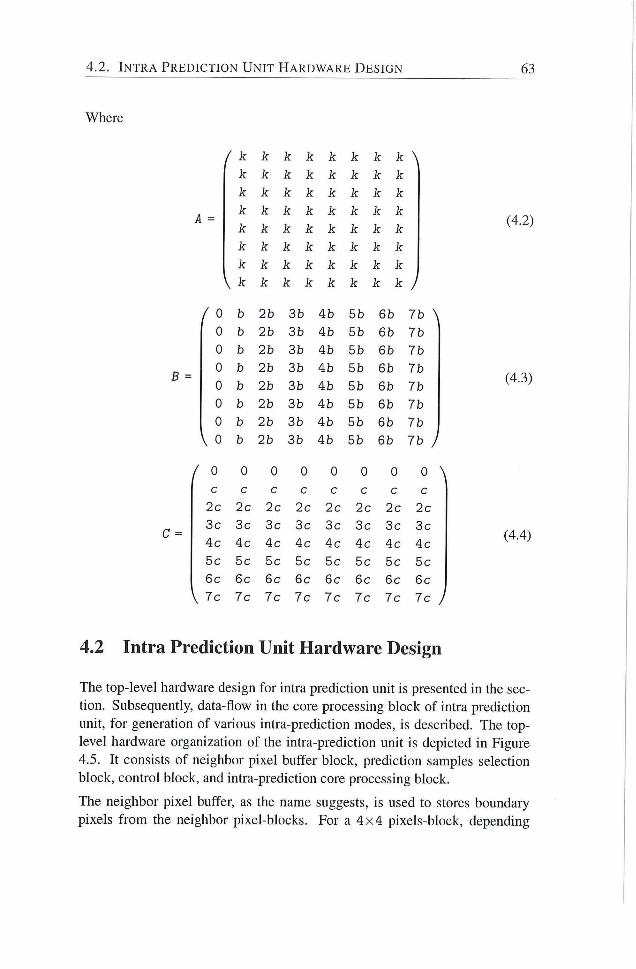
4.2. I N T R A P R E D I C T I O N U N I T H A R D W A R E D E S I G N 63
Where
A =
B =
C =
0
0
0
0
0
0
V 0
/ 0
c
5c
6c
\ 7c
k k k k Ic Jf k \ ic k k k k k k k
k k k k k k k k
k k k k k k k k
k k k k k k k k
k k k k k k k k
k k k k k k k k
\ k k k k k k k k /
b 2b 3b 4b 5b 6b 7b \
h 2b 3b 4b 5b 6b 7b
b 2b 3b 4b 5b 6b 7b
b 2b 3b 4b 5b 6b 7b
b 2b 3b 4b 5b 6b 7b
b 2b 3b 4b 5b 6b 7b
b 2b 3b 4b 5b 6b 7b
b 2b 3b 4b 5b 6b 7b /
0 0 0 0 0 0 0
c c c c c c c
2c 2c 2c 2c 2c 2c 2c
3c 3c 3c 3c 3c 3c 3c
4c 4c 4c 4c 4c 4c 4c
5c 5c 5c 5c 5c 5c 5c
6c 6c 6c 6c 6c 6c 6c
7c 7c 7c 7c 7c 7c 7c
(4.2)
(4.3)
(4.4)
4.2 Intra Prediction Unit Hardware Design
The top4evel hardware design for intra prediction unit is presented in the sec
don. Subsequendy, data-flow in the core processing blocic of intra predicdon
unit, for generation of various intra-prediction modes, is described. The top-
level hardware organization of the intra-prediction unit is depicted in Figure
4.5. I t consists of neighbor pixel buffer block, predicdon samples selection
block, control block, and intra-prediction core processing block.
The neighbor pixel buffer, as the name suggests, is used to stores boundary
pixels f r o m the neighbor pixel-blocks. For a 4 x 4 pixels-block, depending
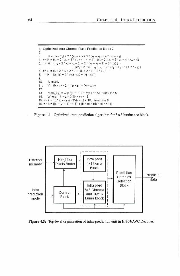
6 4 C H A P T E R 4 . I N T R A P R E D I C T I O N
I . Optimized Intra Chroma Plane Prediction Mode-3 2. 3. H = X2> + 2 ' ( « ; - X l ) + 3 • (Xs - Xo) + 4 ' (X7 - X-i)
4. => H = (Xj + 2 ' Xf + 3 * XR + 4 ' Xy + 4) - (X2 + 2 ' X, + 3 * Xo + 4 • y . , + 4) 5. => H = ( iX j ^ 2 « Xs + Xe + 2) + 2 ' {Xs + X7 + 1) + 2 ' X j ) ) -
6. ( (Xj + 2 ' X| + Xo + 2) + 2 " {>:.-i + x., - 1) + 2 ' x.,) 1 7. => H = (tf + 2 ' S6 + 2 > X-) - (t2 + 2 ' s, + 2 • x.,) 8. => H = (te -1:) + 2 ' {{s?- S i ) + (Xr - x. i))
Cl. 10. Similarly I I . V = ( t 6 - t 2 ) + 2 - ( ( S e - r 3 , ) + { X - - X . i ) )
12. 13. predjx.y] = Clip (fk + b*x + c*y ) » 5), From line 5 14. Where h = a - S'lb + c) + 16 15. => k = 16 ' (X7 + y-) - 3'(b + c) + 16, From line 8 16. => k = <{x, + y: +1) « 4) -({b + c) + ((b + c) •= < 1))
Figure 4.4: Optimized intra-prediction algorithm for 8 x 8 luminance block.
Neighbor I Pixels Buffer
Control Block
Intra pred 4x4 Luma
Block
Intra pred 8x8 Chroma and 16x16 Luma Block
Prediction Samples Selection
Block
Prediction cfeta
Figure 4.5: Top-level organization of intra-prediction unit in H.264/AVC Decoder
4.2. I N T R A P R E D I C T I O N U N I T H A R D W A R E D E S I G N 65
upon the decoding order, block position, and encoding conditions, up to 13
boundary pixels (8-bit each) are stored in neighbor pixel buffer. Similarly, for
16x16 block, it provides storage registers to holds 33 boundary pixels at most.
These boundary pixels are required in core intra prediction processing unit, for
computation of prediction samples. The same buffer is also used to store partial
results during computation of DC and plane intra-prediction modes, in case of
16x16 luma and 8 x 8 , chroma blocks.
A l l processing to compute any given intra-prediction mode takes place in intra
predicdon core processing unit as depicted by dotted block in Figure 4.5. The
detailed intemal design of intra prediction core processing unit is depicted in
Figure 4.6. The vertical and horizontal intra-predicdon modes for all luma and
chroma blocks ( 4 x 4 , 8 x 8 and 16x16) do not require any computadon. The
boundary pixels for these modes bypass the intra-prediction core block (not
depicted in Figure 4.6). In case of 4 x 4 luma intra-predicdon modes 3 to 8, all
unique prediction samples are generated in 1 clock cycle. Similarly, in case
of 4 x 4 luma intra-prediction mode 2 (DC mode), the prediction sample (or
DC value) is computed in 2 clock cycles. This is a vi'orst-case scenario for
luma 4 x 4 intra-prediction modes. The core processing unit computes unique
sample values only. The distribution of these prediction samples to form a 4 x 4
prediction block is performed in the prediction samples selection block. In
case of plane-mode, intra prediction core processing unit takes 6 clock cycles
to computes constants (b, c and k) and the corresponding offset values for b and
c (nb, nc). Using these constants, while computing 16 intra-predicted pixels in
each cycle, all 64 intra-predicted pixels in 8 x 8 chroma predicted-pixels block
are generated in subsequent 4 clock cycles. Therefore, i t takes just 10 clock
cycles in total to dehver the plane-mode, intra 8 x 8 chroma predicted-pixels
block. Similarly 22 clock cycles are required to compute the plane-mode,
intra 16x16 luma predicted-pixels M B .
In most of the 4 x 4 intra-prediction modes, some of the prediction samples
are identical in the final intra-predicted pixels block. Figure 4.7 illustrates this
fact for D D L and V L intra-prediction modes where some of the prediction
samples (tx and Sx in Figure 4.7; defined in Algorithm 4.1) are re-distributed
in the predicted block. For such cases, prediction sample selection unit is
responsible for this re-distribution of unique prediction samples in the final
4 x 4 predicted block accordingly, and transfer it to the next processing unit in
the intra-processing chain of H.264/AVC decoder.
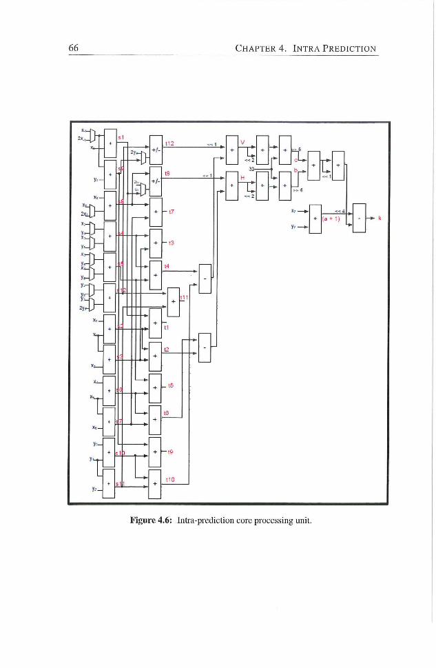
66 C H A P T E R 4 . I N T R A P R E D I C T I O N
Figure 4.6: Intia-piediction core processing unit.
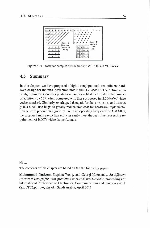
4.3. S U M M A R Y 67
1; •-• t:
!• t:
t , %, t;
t , ; , t .
Mode - 3 Diagonal
Down Left (DDL)
X.- X, X ' X . X , X . 1 X,, 1 X ,
y.. / / Mode - 7 Vertical
Left IVLl
y- ,/ / / Mode - 7 Vertical
Left IVLl
/ / y /'
/ Mode - 7 Vertical
Left IVLl
Y' ^'
/ Mode - 7 Vertical
Left IVLl
t,
/ Mode - 7 Vertical
Left IVLl
5. :. s> t.
/ Mode - 7 Vertical
Left IVLl
S l u S ; t .
/ Mode - 7 Vertical
Left IVLl
s. t,
/ Mode - 7 Vertical
Left IVLl
Figure 4.7: Prediction samples distribution in 4x4 DDL and V L modes.
4.3 Summary
In tiiis ciiapter, we have proposed a high-throughput and area-efficient hard
ware design for the intra-prediction unit in the H.264/AVC. The optimization
of algorithm for 4 x 4 intra prediction modes enabled us to reduce the number
of additions by 60% when compared with those proposed in H.264/AVC video
codec standard. Similarly, overlapped datapath for the 4 x 4 , 8 x 8 , and 16x 16
pixels-block also helps to greatly reduce area-cost for hardware implementa
tion of intra prediction algorithm. With an operating frequency of 150 MHz,
the proposed intra prediction unit can easily meet the real-time processing re
quirement of H D T V video frame formats.
Note.
The contents of this chapter are based on the the fol lowing paper:
Muhammad Nadeem, Stephan Wong, and Georgi Kuzmanov, An Efficient
Hardware Design for Intra-prediction in H.264/AVC Decoder, proceedings of
International Conference on Electronics, Communications and Photonics 2011
(SIECPC),pp. 1-6, Riyadh, Saudi Arabia, Apr i l 2011.

Forward Integer Transform
TH E H.264/AVC, like its predecessors, is a hybrid codec. However, i t is the
first video coding standard that uses an integer inverse-transform design
for its main spatial transform. The corresponding forward transform used in
the encoder is, therefore, also an integer transform. The major advantage of
this forward, inverse transform-pair being integer is that there is no possibility
of a mismatch between standard-compliant encoder and decoder. The previous
video coding standards such as H.261, H.262/MPEG-2, H.263, MPEG-1 and
MPEG-4 part 2 ad suffers encoder-decoder mismatch problem.
In a video encoder, forward integer transform is used to de-correlate video data
at 4 x 4 predicted pixels-block level, preceding the quantizadon process. Be
side integer transform, H.264/AVC standard also apply Hadamard transform to
a block of DC-values in a macroblock for both luma and chroma components
of video signal. The forward and inverse integer transform is computed for
each 4 x 4 predicted block along with Hadamard transform for DC- blocks in
a H.264/AVC video encoder. Additionahy, the Hadamard transform is com
monly used to compute Sum of Absolute Transformed Difference (SATD), as
part of intra-mode decision process to choose best prediction block in inter-
frame encoding process. The spadal transform processing in H.264/AVC
codec is, therefore, one of the top 3 compute-intensive processing units in
H.264/AVC codec.
In this chapter, we propose efficient hardware designs for reahzation of for
ward integer transform in H.264/AVC video encoder. The main contributions
of this chapter are as fohows:
1. A low-power, area-efficient hardware design to realize forward integer
transform in H.264/AVC encoder. This design targets image compres
sion applications, running on battery-powered electronic devices, such
as Digital Sdh Cameras (DSC).
69
70 C H A P T E R 5. F O R W A R D I N T E G E R T R A N S F O R M
2. For real-time video compression applications, a high-throughput, low-
latency, and area-efficient hardware design to realize forward integer
transform in H.264/AVC encoder.
The chapter is organized as follows: Sections 5.1 and 5.2 describe the proposed
solutions for image processing apphcations and real-time video processing ap
phcations respectively. Finally, Section 5.3 summarizes the chapter
5.1 Forward Integer Transform for Image Processing Applications
In this section, we propose a solution to realize forward integer transform for
image processing/compression apphcations using H.264/AVC codec. Since
image processing applications are typically not real-time applications, there
fore, compression-tiine or throughput of image compression engine is of less
importance. However, as most of these apphcations nm on battery-powered
electronic devices, dynamic-power-consumption reduction is of prime impor
tance for such applications.
Image compression applications compress the input image using intra-
encoding technique. H.264/AVC video coding standard suppoits multiple di
rectional intra-predicdon modes to reduce spadal redundancy in the input sig
nal. Putting it more precisely, H.264/AVC supports 4 intra-prediction modes
at 16x16 pixels-block level and 9 intra-predicdon modes at 4 x 4 pixels-block
level, to significantly reduce the predictive enor by exploiting spatial correla
tion between block to be encoded and its already encoded neighboring blocks
in the input image or a frame. When a current pixles-block is to be encoded in
intra-mode, a conesponding prediction block is formed using previously en
coded and reconstructed pixels-blocks. Intra-prediction-mode-decision unit in
an encoder, is responsible to determine the best intra-prediction mode for to be
encoded cunent pixels-block at hand. The reference software for H.264/AVC
encoder udlizes a Lagrange cost funcdon to make an intra-predicdon mode
decision and the cost for an intra-prediction mode is computed as follows:
JMode (MBk ,Ik\Qp, Aftode ) = D (MBk ,Ik\Qp) + A;.,ode * R (MBj, ,Ik\Qp, ><Mode )
(5.1)
Where Ajviode < E) and R represent Lagrange parameter, distortion and rate, re
spectively. The rate (R) is estimated by number of bits to encode the mode.
5 . 1 . F O R W A R D I N T E G E R T R A N S F O R M FOR I M A G E P R O C E S S I N G
A P P L I C A T I O N S 7 1
while, distortion (D) is measured using Sum of Absolute Difference (SAD) or
Sum of Absolute Transformed Differences (SATD) for residual pixels-block
data. SATD, however, is more precise in estimating the distortion and, there
fore, helps to provide better image quahty. The H.264/AVC reference soft
ware utihzes Hadamard transform to compute frequency domain coefficients
of a residual block for candidate intra-prediction mode [99]. The distortion
D in Equation. 5.1 is estimated by using the absolute sum of all Hadamard
transformed coefficients.
We follow a different approach f rom related works cited in Section 2.3.3.
As mentioned earher, Hadamard-transformed residual block is used to esti
mate distortion (D) for the candidate intra-prediction mode iMode in an intra-
predichon-mode-decision unit [99]. We propose to use same Hadamard-
transformed residual block of the selected intra-prediction mode and derive
the forward-integer-transformed coefficients for residual block in H.264/AVC
compliant encoder This approach requires less than half the number of ad
ditions (30 vs. 64) when compared with those for state-of-the-art designs in
literature.
5.1.1 S-Transform: Hadamard-transformed Coefficients to Integer-transformed Coefficients Conversion
H.264/AVC udhzes an integer transform (C) to convert spacial domain 4 x 4
residual pixel block (X) into frequency domain (Z) as follows: .
Z = C-X-C^ (5.2)
where
/ 1 2
1
V 1
1 1
1 - 1
- 1 - 1
- 2 2
1 \
- 2
1
- 1 /
(5.3)
Similarly, 2-D Hadamard transformed coefficients (Y) for 4 x 4 input pixels-
block (X) s are computed using the Hadamard transform (H) as follows:
(5.4)
72 C H A P T E R 5. F O R W A R D I N T E G E R T R A N S F O R M
where
/ 1
H =
1 1
1 1 - 1
1 - 1 - 1
V 1 - 1 1
- 1
1
- 1 y
(5.5)
I f S is such a transform that it can be used to convert the Hadamard transformed
coefficients (Y) into integer transformed coefficients (Z) Z , then for 1-D case,
we can write as follows:
S = C-H' (5.6)
where S is provided as follows:
S =
/ 1
0
0
\ 0
0
1.5
0
0 0 \
0 0 .5
1 0
-0.5 0 1.5 /
/ 1 0 0
0 1 0
0 0 1
V 0 0 0
0 \
0
0
/ 0 0
0 0.5
0 0
V 0 - 0 . 5
0 \
0 .5
0
0 .5 y (5.7)
5.1.2 Signal-flow for 1-D S-Transform
The proposed 1-D, S-transform in Equadon 5.7 takes the Hadamard trans
formed coefficients and derive the integer transform coefficients. Only 4 ad
ditions and 2 shift operations are required for the implementation of 1-D, S-
transform. While, on the other hand, a fast 1 -D forward integer transform
algorithm presented in [22] requires 8 additions along with 2 shift operations
to compute the same integer-transformed results f rom intra-predicted residual
block. The signal flow diagram for 1-D, S-transform is depicted in Figure 5.1.
5.1.3 2-D, S-Transform Algorithm
For 1-D S-transform computation case, only two Hadamard-transformed co
efficients are required to be processed for any given column or row in Y, as
depicted in Figure5.1(a). A 2-D integer transform can be reahzed using two
1-D S-transform, depicted in Figure 5.2. This approach, however, has an over
head as it requires a transpose unit between two successive 1-D transforms.
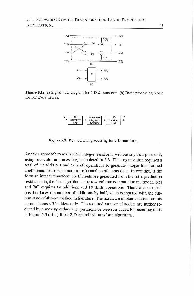
5.1 . F O R W A R D I N T E G E R T R A N S F O R M FOR I M A G E P R O C E S S I N G
A P P L I C A T I O N S 73
Yd)-
Ye5-
X
(3)
Yd}-
Yi3)-
-31)
- 3 3 )
(b)
3C'i
35.;
32)
Figure 5.1: (a) Signal flow diagram for 1-D S-transform, (b) Basic processing block for 1-D S-transform.
ID — * • — & r3-aï:ïn-i
LHt
Figure 5.2: Row-column processing for 2-D transform.
Another approach to realize 2-D integer transform, without any transpose unit,
using row-column processing, is depicted in 5.3. This organization requires a
total of 32 additions and 16 shift operadons to generate integer-transformed
coefficients f rom Hadamard-transformed coefficients data. In contrast, i f the
forward integer transform coefficients are generated f rom the intra prediction
residual data, the fast algorithm using row-colunm computadon method in [95]
and [80] requires 64 additions and 16 shifts operations. Therefore, our pro
posal reduces the number of additions by half, when compared with the cur
rent state-of-the-art method in hterature. The hardware implementation for this
approach costs 32 adders only. The required number of adders are further re
duced by removing redundant operations between cascaded P processing units
in Figure 5.3 using direct 2-D optimized transform algorithm .
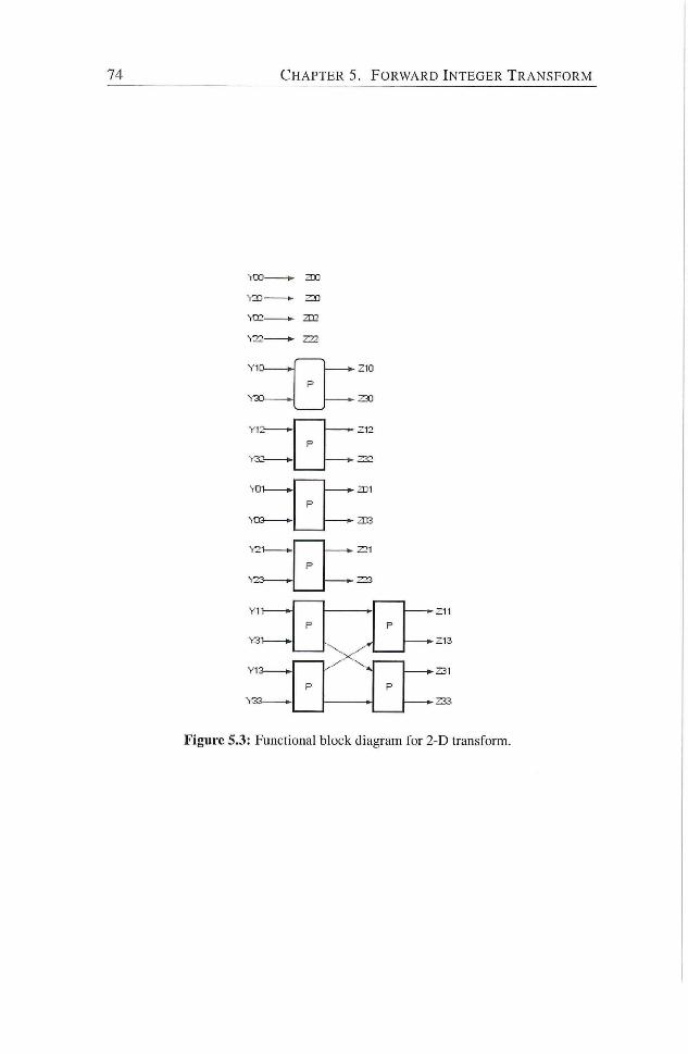
74 C H A P T E R 5. F O R W A R D I N T E G E R T R A N S F O R M
310
ZD2
•Z10
• Z30
• Z12
^ 3
Figure 5.3: Functional blocic diagram for 2-D transform.
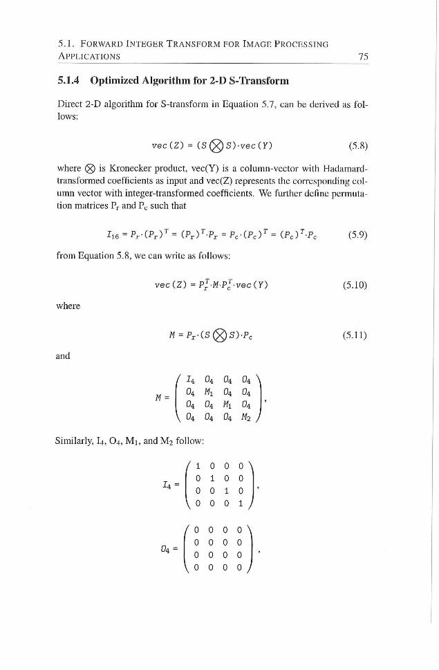
5.1 . F O R W A R D I N T E G E R T R A N S F O R M FOR I M A G E P R O C E S S I N G
A P P L I C A T I O N S 75
5.1.4 Optimized Algorithm for 2-D S-Transform
Direct 2-D algorithm for S-transform in Equation 5.7, can be derived as f o l
lows:
veciZ) = (Sl^S)-vec(Y) (5.8)
where 0 is Kronecker product, vec(Y) is a column-vector with Hadamard-
transformed coefficients as input and vec(Z) represents the corresponding col
umn vector with integer-transformed coefficients. We further define permuta
tion matrices Pr and Pc such that
I l 6 = P r - ( F r ) ^ = (PrV-Pr = Pc-iPc)^ = iPc^-Pc (5.9)
f rom Equation 5.8, we can write as follows:
vec ( Z ) = Pl-M-Pl-vec{Y) (5.10)
where
W = Pr - (S (g )S) -Pc (5.11)
and
/ I4 O4 O4 D4 \ O4 Ml D4 O4 O4 O4 Ml O4
V O4 O4 O4 M2 /
Similarly, I4, O4, M i , and M 2 follow:
14 =
/ I 0 0
0 1 0 0
0 0 1 0
V 0 0 0 1 /
( ° 0 0 0 \
0 0 0 0
0 0 0 0
\ o 0 0 0 /
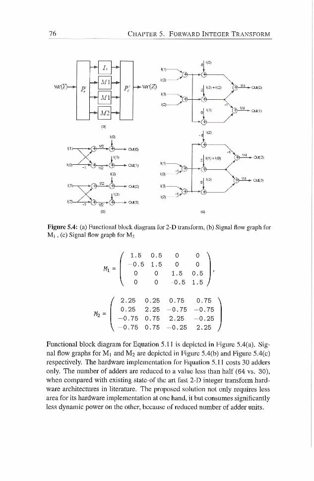
76 C H A P T E R 5. F O R W A R D I N T E G E R T R A N S F O R M
Ml
1.0,
I;
i
A- i
Ki)-i
K1)-
1(2)
2 1(3)+K3 i3 » cmc)
^ ^ ^ ^
cu;2)
Figure 5.4: (a) Functional block diagram for 2-D transfonn, (b) Signal flow graph for M l , (c) Signal flow graph for M2
/ 1.5 0.5 0 0 ^
- 0 . 5 1.5 0 0
0 0 1.5 0.5
0 0 - 0 . 5 1.5 }
/ 2. 25 0 .25 0.75 0.75 \ 0. 25 2 25 - 0 . 7 5 - 0 . 7 5
-0 .75 0 75 2.25 - 0 . 2 5
V --0 .75 0 75 - 0 . 2 5 2.25 /
M, =
Functional block diagram for Equation 5.11 is depicted in Figure 5.4(a). Sig
nal flow graphs for M j and M 2 are depicted in Figure 5.4(b) and Figure 5.4(c)
respectively. The hardware implementation for Equation 5.11 costs 30 adders
only. The number of adders are reduced to a value less than half (64 vs. 30),
when compared with existing state-of the art fast 2-D integer transform hard
ware architectures in hterature. The proposed solution not only requires less
area for its hardware implementation at one hand, it but consumes significantly
less dynamic power on the other, because of reduced number of adder units.
5.2. F O R W A R D I N T E G E R T R A N S F O R M FOR V I D E O P R O C E S S I N G
A P P L I C A T I O N S 77
5.2 Forward Integer Transform for Video Processing Applications
The intra prediction process, as explained in Section4.1, requires reconstracted
pixels f rom neighbor blocks. Therefore, intra prediction process for next block
is not started until the cuiTcnt block in not reconstructed and its pixels are not
available for prediction. Video processing applications using intra-frames only,
therefore, require eflicient processing chain for real-time processing of high-
resolution videos. A low-latency and high-throughput forward integer trans
form unit is very important requirement for an efficient intra frame processing
chain. The straightforward solution for low-latency is to implement forward
integer transform unit in parallel with intra-prediction mode decision unit. De
pending on the outcome of intra-prediction mode decision unit, the forward in
teger transformed block for the selected intra-prediction mode is readily avail
able for the next processing unit in the intra-frame processing chain with zero
latency. This approach provides an efficient soludon for latency issue. The
area cost for this proposed solution is reduced by reusing intermediate results
f rom Hadamard transform unit in the intra-frame processing chain. Wi th our
proposal, not only the number of operations to realize integer transform are sig
nificantly reduced (32 vs. 64) but effective latency penalty diminishes as the
proposed computation for the integer transform are removed f rom the critical
path.The remainder of this secdon describes our approach to idendfy common
intermediate results and the hardware design for its implementadon.
5.2.1 2-D Forward Integer Transform Algorithm
From Equations 5.2 and 5.5, the 2-D 4 x 4 integer transform and 2-D Hadamard
transform can be expressed as follows:
v e c ( Z ) = ( C ( g ) C ) - v e c ( X ) (5.12)
v e c ( 7 ) = ( H ( g ) f f ) - v e c ( X ) (5.13)
where 0 is Kronecker product, vec(X) is a column-vector with residual pixel
data, vec(Y), and vec(Z) are corresponding column-vectors with Hadamard-
transformed coefficients and integer-transfoiTned coefficients respectively. We
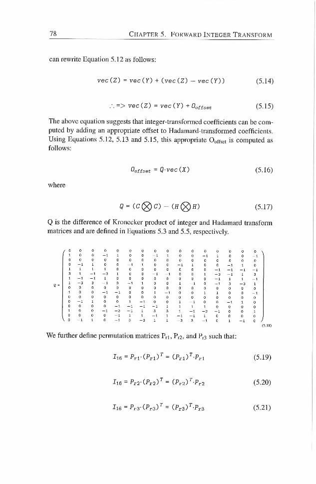
78 C H A P T E R 5. F O R W A R D I N T E G E R T R A N S F O R M
can rewrite Equation 5.12 as follows:
vecCZ) = vec(Y) + (vec(Z) - v e c ( 7 ) ) (5.14)
.-. = > v e c ( Z ) = veciY) + Ooffset (5.15)
The above equation suggests that integer-transformed coefhcients can be com
puted by adding an appropriate offset to Hadamard-transformed coefficients.
Using Equations 5.12, 5.13 and 5.15, this appropiiate Ooffset is computed as
follows:
O o f f s e t = Q-vec(X) (5.16)
where
Q = ( C ( g ) C ) - ( J f (g )H) (5.17)
Q is the difference of Kronecker product of integer and Hadamard transform
matrices and are defined in Equations 5.3 and 5.5, respectively.
V 0
0 0 0
- 1 0 0 0 1 0 0 0 1 1 1
- 1 - 3
0 0
- 1
- 3 - 1 1
- 3 0 0 0 1 0 0 0
(5.18)
We further define permutation matrices Pri, Pr2, and Pr3 such that:
I l 6 = P r l - ( P r l ) ^ = i P r l V - P r l (5.19)
I l 6 = P r 2 - ( P r 2 ) ^ = ( P r 2 ) ^ - P r 2
I l 6 = P r 3 ' ( P r 3 ) ^ = ( P r s V - P r S
(5.20)
(5.21)
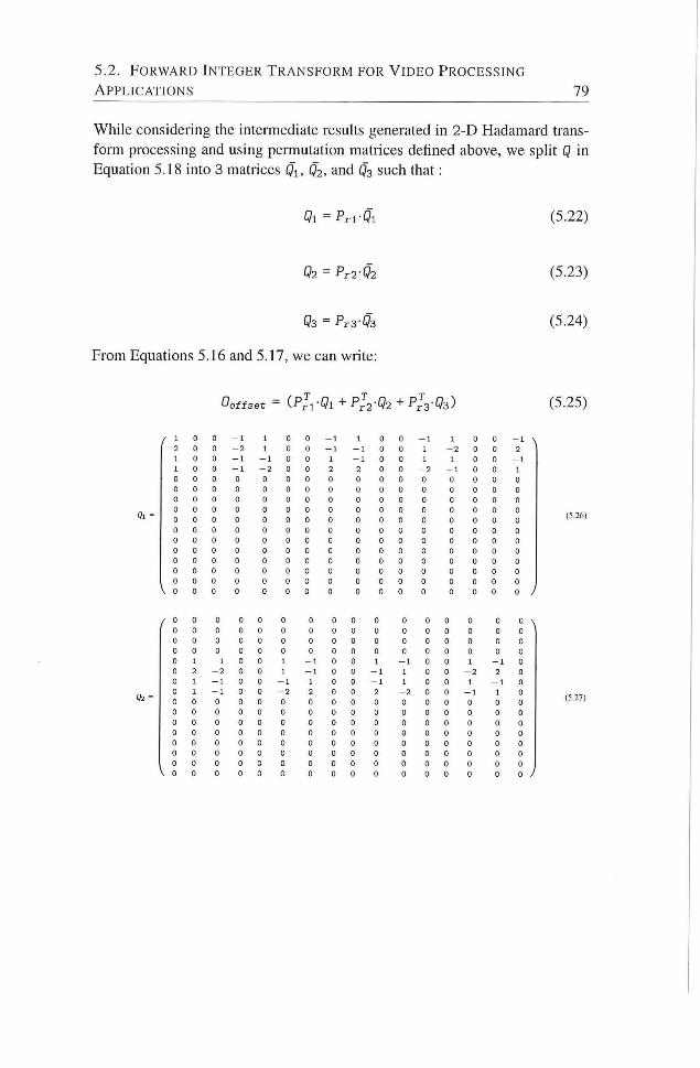
5.2. F O R W A R D I N T E G E R T R A N S F O R M FOR V I D E O P R O C E S S I N G
A P P L I C A T I O N S 79
While considering the intennediate results generated in 2-D Hadamard trans
form processing and using permutation matrices defined above, we spht Q in
Equation 5.18 into 3 matrices Qi, Ö 2 . and Ö 3 such that:
Ql = PrvQl (5.22)
O2 = P r 2 - Q 2
Q3 = P r 3 - Ö 3
From Equations 5.16 and 5.17, we can write:
(5.23)
(5.24)
0 o f f s e t = (P T
r l ' Ql + Pr2 •Q2 + P T
r3' Q3)
I 0 0 - 1 1 0 0 — 1 1 0 0 —1 1 0 0 - 1 2 0 0 - 2 1 0 0 - 1 -1 0 0 1 —2 0 0 2 1 0 0 - 1 - 1 0 0 1 -1 0 0 1 1 0 0 - 1 1 0 0 - 1 - 2 0 0 2 2 0 0 - 2 - 1 0 0 1 0 0 0 0 0 0 0 0 0 0 0 0 0 0 0 0 0 0 0 0 0 0 0 0 0 0 0 0 0 0 0 0 0 0 0 0 0 0 0 0 0 0 0 0 0 0 0 0 0 0 0 0 0 0 0 0 0 0 0 0 0 0 0 0 0 0 0 0 0 0 0 0 0 0 0 0 0 0 0 0 0 0 0 0 0 0 0 0 0 0 0 0 0 0 0 0 0 0 0 0 0 0 0 0 0 0 0 0 0 0 0 0 0 0 0 0 0 0 0 0 0 0 0 0 0 0 0 0 0 0 0 0 0 0 0 0 0 0 0 0 0 0 0 0 0 0 0 0 0 0 0 0 0 0 0 0 0 0 0 0 0 0 0 0 0 0 0 0 0 0 0 0 0 0 0 0 0 0 0 0 0 0 0 0 0 0 0 0 0 0 0 0
0 0 0 0 0 0 0 0 0 0 0 0 0 0 0 0 0 0 0 0 0 0 0 0 0 0 0 0 0 0 0 0 0 0 0 0 0 0 0 0 0 0 0 0 0 0 0 0 0 0 0 0 0 0 0 0 0 0 0 0 0 0 0 0 0 1 - 1 0 0 1 — 1 0 0 1 - 1 0 0 1 - 1 0 0 2 - 2 0 0 1 - 1 0 0 - 1 1 0 0 - 2 2 0 0 1 - 1 0 0 - 1 1 0 0 - 1 1 0 0 1 - 1 0 0 1 - 1 0 0 —2 2 0 0 2 —2 0 0 - 1 1 0 0 0 0 0 0 0 0 n 0 0 0 0 0 0 0 0 0 0 0 0 0 0 0 0 0 0 0 0 0 0 0 0 0 0 0 0 0 0 0 0 0 0 0 0 0 0 0 0 0 0 0 0 0 0 0 0 0 0 0 0 0 0 0 0 0 0 0 0 0 0 0 0 0 0 0 0 0 0 0 0 0 0 0 0 0 0 0 0 0 0 0 0 0 0 0 0 0 0 0 0 0 0 0 0 0 0 0 0 0 0 0 0 0 0 0 0 0 0 0 0 0 0 0 0 0 0 0 0
(5.25)
(5.26)
(5.27)
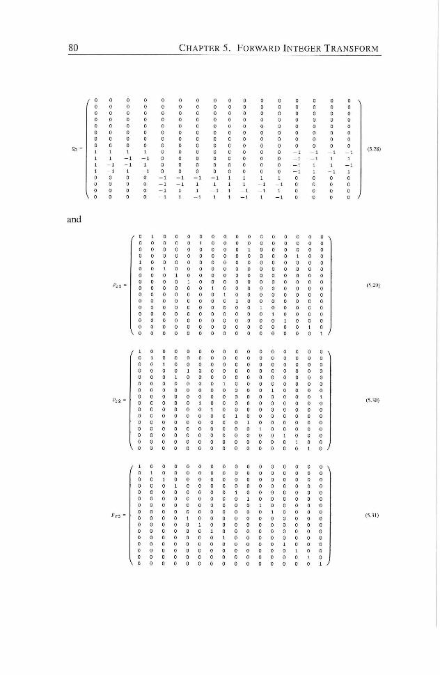
80 C H A P T E R 5. F O R W A R D I N T E G E R T R A N S F O R M
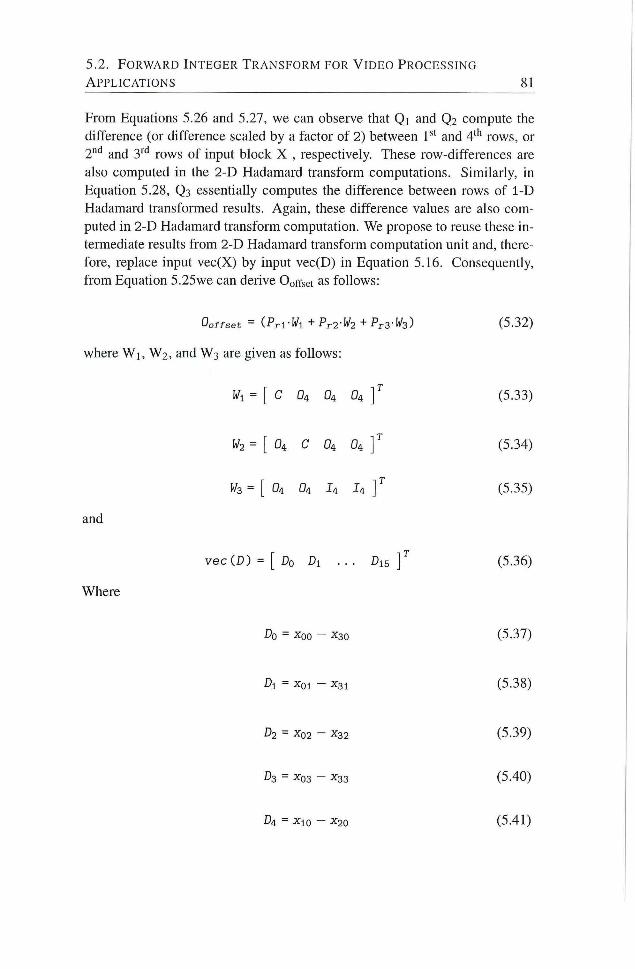
5.2. F O R W A R D I N T E G E R T R A N S F O R M FOR V I D E O P R O C E S S I N G
A P P L I C A T I O N S 81
From Equations 5.26 and 5.27, we can observe that Qi and Q 2 compute the
difference (or difference scaled by a factor of 2) between l * " and 4'^ rows, or
ï " ' and S"* rows of input block X , respectively. These row-differences are
also computed in the 2-D Hadamard transform computations. Similarly, in
Equation 5.28, Q3 essentially computes the difference between rows of i - D
Hadamard transformed results. Again, these difference values are also com
puted in 2-D Hadamard transform computation. We propose to reuse these in
termediate results f rom 2-D Hadamard transform computation unit and, there
fore, replace input vec(X) by input vec(D) in Equation 5.16. Consequendy,
f rom Equation 5.25we can derive Ooffset as follows:
O o f f s e t = ( P r l - I ^ l + P r 2 - l ^ 2 + P r S ' I ^ s ) (5.32)
where W i , W 2 , and W 3 are given as follows:
Wi = [ C D4 O4 O4 ] ' (5.33)
W2 = [ O4 C O4 O4 ] ' (5.34)
= [ O4 O4 I4 I4 ] ' (5.35)
and
veciD) = [ D O Di . . . Di5 ] ^ (5.36)
Where
Do = ^ 0 0 - ^30 (5.37)
Dl = xoi - X 3 1 (5.38)
D2 = X02 - X 3 2 (5.39)
O3 = - X33 (5.40)
D4 = Xio - X20 (5.41)
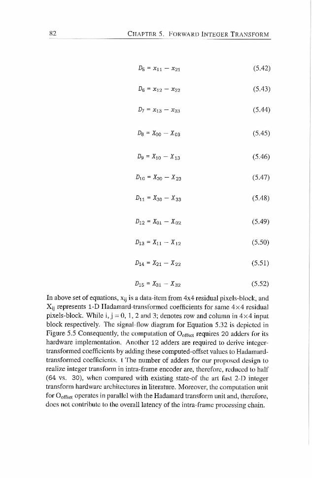
82 C H A P T E R 5. F O R W A R D I N T E G E R T R A N S F O R M
DB = Xn - X21 (5.42)
De = - X22 (5.43)
Df = xi3 - X23 (5.44)
Ds = Xoo - Xo3 (5.45)
Dg = Xio - Xi3 (5.46)
Dio = X20 - X23 (5.47)
Dn = X30 - X33 (5.48)
D12 = Xoi - X02 (5.49)
Di3 = Xn - X 1 2 (5.50)
Du = X21 - X22 (5.51)
DiB = X31 - X32 (5.52)
In above set of equations, xy is a data-item f rom 4x4 residual pixels-block, and
Xi j represents 1-D Hadamard-transformed coefficients for same 4 x 4 residual
pixels-block. While i , j = 0, 1, 2 and 3; denotes row and column in 4 x 4 input
block respectively. The signal-flow diagram for Equation 5.32 is depicted in
Figure 5.5 Consequently, the computation of Ooffset requires 20 adders for its
hardware implementation. Another 12 adders are required to derive integer-
transformed coefficients by adding these computed-offset values to Hadamard-
transformed coefficients, t The number of adders for our proposed design to
realize integer transform in intra-frame encoder are, therefore, reduced to half
(64 vs. 30), when compared with exisdng state-of the art fast 2-D integer
transform hardware architectures in literature. Moreover, the computation unit
for Ooffset operates in parallel with the Hadamard transform unit and, therefore,
does not contribute to the overall latency of the intra-frame processing chain.
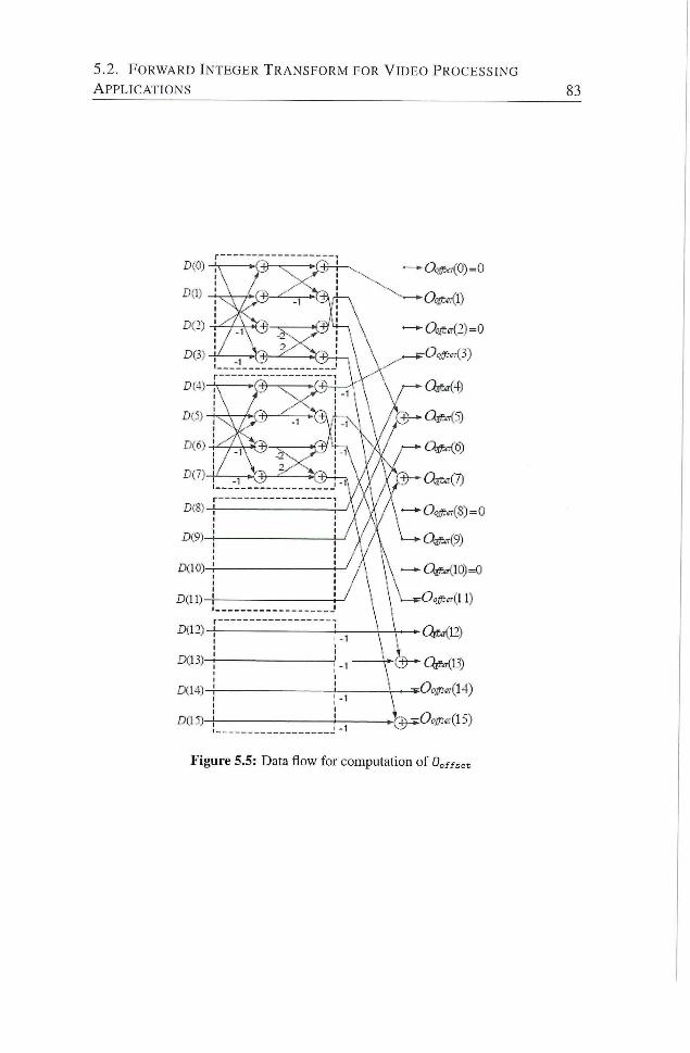
5.2. F O R W A R D I N T E G E R T R A N S F O R M FOR V I D E O P R O C E S S I N G
A P P L I C A T I O N S
Figure 5.5: Data flow for computation of Ooftset
84 C H A P T E R 5. F O R W A R D I N T E G E R T R A N S F O R M
5.3 Summary
In this chapter, we have presented two solutions for realization of integer trans
form in the processing chain of intra-frame encoder applications. The first
solution targets image compression apphcations running on battery-powered
electronic devices, such as digital still camera. The proposed solution utilizes
a novel 2-D transform to derive integer-transformed coefficients directly f rom
that of Hadamard-transformed coefficients with significantly reduced number
of operations and, therefore, area and power consumption. The second solu
tion targets real-time video compression apphcations using intra-frames only.
The proposed solution reduces the effective latency penalty of forward integer
transform to zero. Moreover, it aggressively reuses the intermediate results
f rom Hadamard transform and, therefore, requires significantly reduced num
ber of operations and, thus, less area for its hardware implementation.
Note.
The content of this chapter is based on the the fol lowing paper:
Muhammad Nadeem, Stephan Wong, and Georgi Kuzmanov, An Efficient
Realization of Fonvard Integer Transform in H.264/AVC Intra-frame Encoder
, proceedings of International Conference on Embedded Computer Systems:
Architectures, Modeling, and Simuladon (SAMOS) 2010, pp. 71-78, Samos,
Greece, l u ly 2010.
6 Inverse Integer Transform
THE H.264/AVC is a bloclc-based, hybrid video coding standard that utihzes
a spatial, DCT-based integer inverse-transform design in its compression
engine to avoid encoder-decoder mismatch. Although, the transformation can
be carried out by addition operations only, i t is one of the top 3 compute-
intensive processing modules in H.264/AVC decoder. In this chapter, we pro
pose two hardware designs for inverse integer transform unit in H.264/AVC
compliant video encoder and decoder.
The main contribudons of this chapter are:
1. A proposal to compute inverse integer transform on-the-fly and a low-
latency hardware design for inverse integer transform unit in an intra-
frame encoder processing chain.
2. Derivation of data-driven algorithm for inverse integer transform in
H.264/AVC with variable number of operations.
3. Low-power, high-throughput hardware design for inverse integer trans
form unit based on data-driven algorithm.
The chapter is organized as follows: In Secdon, 6.1, we briefly provide a mo
tivation for low-latency inverse integer transform. Subsequently, a hardware
design for low-latency inverse integer transform is provided in the same sec
don. In Section 6.2, a data-driven algorithm for inverse integer transform is de
scribed. A low-power, high-throughput hardware design based on data-driven
algorithm is also presented at the end of this secdon. Finally, Section 6.3 sum
marizes the chapter.
85
8 6 C H A P T E R 6 . I N V E R S E I N T E G E R T R A N S F O R M
6.1 Low-Latency Inverse Integer Transform
In this section, we first describe our approach for the low-latency and area-
efficient soludon for the inverse integer transform unit. Subsequently, the al
gorithm and the corresponding architecture for the inverse integer transform
unit are described.
A typical implementadon of forward and inverse quandzadon units, f rom the
perspective to reduce multiplier's area-cost, processes the input data either se
rially or four data-items in parallel. Similarly, the hardware unit for inverse in
teger transform, depending upon implemented algorithm, requires one-fourth,
half, or a complete 4 x 4 input block of data to start its processing. Therefore,
an additional buffer is required for pipeline its implementation or a delay is to
be introduced before start of inverse integer transform process. Moreover, most
of inverse integer transform algorithms assume that all 4 x 4 input block data-
items are non-zero. Consequently, these algorithms perform constant number
of operations per block in order to compute inverse integer transform for a
given block of input data.
However, in digital video coding, it is very common that a substantial number
of spatial high-frequency transformed-coefficients of residual block are quan
tized to zero. A typical transformed and quantized residual block contains few
non-zero coefficients in the low-frequency region and mostly zero-valued co
efficients in the high-frequency region. From inverse integer transform unit's
perspective, while decoding incoming video bitstream in decoder or during (in
verse) quantization process in encoder, i t is already known for that how many
and at what positions in a 4 x 4 input data-block, the transformed-quantized
coefficients are non-zero and, therefore, how shall they contribute to the pixel
values for the reconstructed block. A considerable amount of computations
can be saved by exploiting this information, while developing an algorithm for
inverse integer transform.
In this work, we have followed a different approach and derived a serial al
gorithm for inverse integer transform unit. The hardware unit for inverse in
teger transform, based on serial processing algorithm, directly interfaces with
the inverse quantization unit, without requiring any additional buffer or delay.
Inverse integer transform unit processes the incoming inverse-quantized data
items on-the-fly and accumulates their contribution towards the final value for
the inverse integer transformed block or residual block. With this approach,
latency penalty is significantly reduced. In case of zero-valued incoming data-
item, the processing for this particular data-item is skipped in order to avoid
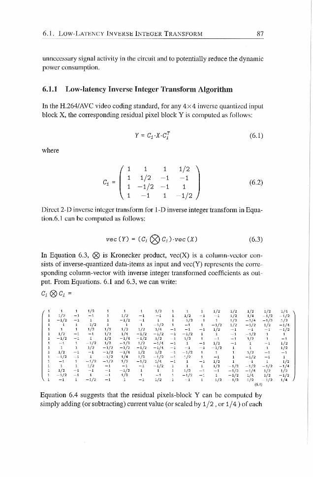
6 .1 . L O W - L A T E N C Y I N V E R S E I N T E G E R T R A N S F O R M 87
unnecessary signal activity in the circuit and to potendahy reduce the dynamic
power consumpdon.
6.1.1 Low-latency Inverse Integer Transform Algorithm
In the H.264/AVC video coding standard, for any 4 x 4 inverse quantized input
block X, the corresponding residual pixel block Y is computed as follows:
where
Ci =
/ 1 1 1 1/2 \
1 1/2 - 1 - 1
1 - 1 / 2 - 1 1
V 1 - 1 1 - 1 / 2 /
(6.1)
(6.2)
Direct 2-D inverse integer transform for 1-D inverse integer transfoim in Equa-
don.6.1 can be computed as follows:
vec(Y) = {Ci(S<)Ci)-vec(X) (6.3)
In Equation 6.3, is Kronecker product, vec(X) is a column-vector con
sists of inverse-quandzed data-items as input and vec(Y) represents the corre
sponding column-vector with inverse integer transformed coefficients as out
put. Erom Equations. 6.1 and 6.3, we can write:
V 1
1 1 1 1/2 1 1 1 1/2 1 1 1 1/2 1/2 1/2 1/2 1/4 ^ 1 1/2 - 1 - 1 1 1/2 - 1 - 1 1 1/2 - 1 - 1 1/2 1/4 - 1 / 2 - 1 / 2 1 - 1 / 2 - 1 1 1 - 1 / 2 - 1 1 1 - 1 / 2 - 1 1 1/2 - 1 / 4 - 1 / 2 1/2 1 - 1 1 - 1 / 2 1 - 1 1 - 1 / 2 1 - 1 1 - 1 / 2 1/2 - 1 / 2 1/2 - 1 / 4 1 I 1 1/2 1/2 1 /2 1/2 1/4 - 1 - 1 - 1 1/2 - 1 - 1 - 1 - 1 / 2 1 1/2 - 1 - 1 1/2 1/4 - 1 / 2 - 1 / 2 - 1 - 1 / 2 1 1 — 1 - 1 / 2 1 1 1 - 1 / 2 - 1 1 1/2 - 1 / 4 - 1 / 2 1/2 - 1 1/2 1 — 1 — 1 1/2 1 - 1 1 - 1 1 - 1 / 2 1/2 - 1 / 2 1/2 - 1 / 4 - 1 1 - 1 1/2 - 1 1 - 1 1/2 1 1 1 1/2 - 1 / 2 - 1 / 2 - 1 / 2 - 1 / 4 - 1 - 1 - 1 - 1 / 2 1 1 1 1/2 1 1/2 — 1 - 1 - 1 / 2 - 1 / 4 1/2 1/2 - 1 - 1 / 2 I 1 1 1/2 - 1 - 1 1 - 1 / 2 - 1 1 - 1 / 2 1/4 1/2 - 1 / 2 - 1 1/2 1 - 1 1 - 1 / 2 - 1 1 1 - 1 1 - 1 / 2 - 1 / 2 1 /2 - 1 / 2 1/4 - 1 1 - 1 1/2 1 - 1 1 - 1 / 2 1 1 1 1/2 — 1 - 1 - 1 - 1 / 2 1 1 1 1 /2 - 1 / 2 - 1 / 2 - 1 / 2 - 1 / 4 1 1/2 — 1 - 1 - 1 - 1 / 2 1 1 1 1/2 - 1 - 1 - 1 / 2 - 1 / 4 1/2 1/2 1 - 1 / 2 - 1 1 - 1 1/2 1 - 1 1 - 1 / 2 - 1 1 - 1 / 2 1/4 1/2 - 1 / 2 ,
1/4 J 1 - 1 1 - 1 / 2 - 1 1 - 1 1/2 1 - 1 1 - 1 / 2 - 1 / 2 1/2 - 1 / 2 - 1 / 2 ,
1/4 J (6.4)
Equation 6.4 suggests that the residual pixels-block Y can be computed by
simply adding (or subtracdng) current value (or scaled by 1/2 , or 1 / 4 ) of each
88 C H A P T E R 6. I N V E R S E I N T E G E R T R A N S F O R M
given input coefficient Xy to tiie accumulated values for the output block data-
items Y i j . Therefore, the serial inverse integer transform algorithm requires
only one register to hold incoming input data-item and 16 registers to hold
pardal or accumulated resuks for the output block data-items Yy. Similarly,
16 add/sub units are required to add the current (or scaled) value to the already
accumulated pardal results. The accumulator is initialized to zero at the start
of each input block. As soon as the last data-item of the input block arrives, the
corresponding residual pixel block Y is available at the output of the inverse
integer transform unit. With this approach, inverse-quantized data-items Xy
from the inverse quandzadon unit are processed on-the-fly without introducing
any delay for the computation of the residual pixel block. Moreover, only
non-zero input data-items are stored in the input register of inverse integer
transform unit for processing. This helps to reduce the unnecessary signal
acdvity in the circuit which can, therefore, contribute to potentially reduce the
dynamic power consumption especially at coarser quandzadon parameter (Qp)
value and/or smoother regions of the video frame being processed.
6.1.2 Low-latency Inverse Integer Transform Hardware Design
In this section, high-level organization of low-latency inverse integer transform
unit is introduced. The design is based on inverse integer transform algorithm
introduced in Secdon 6.1.1. Subsequently, hardware design of basic process
ing unit along with control unit is explained.
High Level Organization The functional block diagram of inverse integer
transform unit is depicted in Figure 6.1. The proposed design takes inverse-
quantized coefficient (X_val) and its position in the input-block as inputs to
the hardware unit. In case this input inverse-quantized coefficient is non-zero,
it is stored in a register (InReg) as depicted in Figure 6.1. Fx processing blocks
hold the partial or final computed value of each residual-pixel-bock data-hems
Yy. There are 16 such processing blocks in order to compute a complete 4 x 4
residual pixels-block.
Hardware Design for Basic Processing Unit The internal design of Pxblock
is depicted in Figure 6.2. This block consists of one muldplexer (Mux) at the
input, one accumulator register Acc, and one Add/Sub unit. Mux is used to
select the correct contribudon of input inverse-quantized data-item to compute
Yy, while Acc register holds pardal results during processing. Reset control
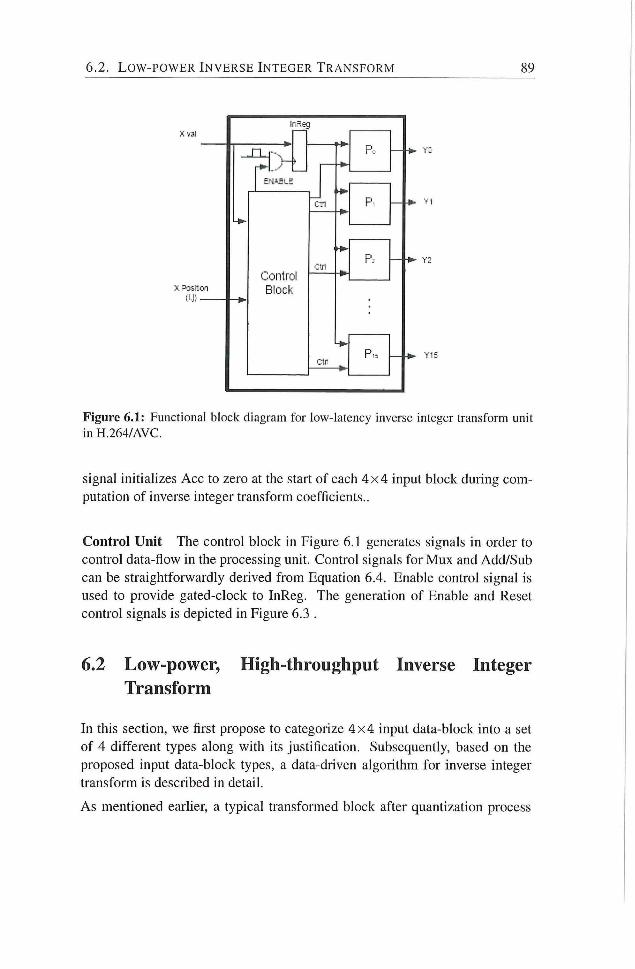
6.2. L O W - P O W E R I N V E R S E I N T E G E R T R A N S F O R M 89
Figure 6.1: Functional block diagram for low-latency inverse integer transform unit in H.264/AVC.
signal initializes Acc to zero at the start of each 4 x 4 input block during com
putation of inverse integer transform coefficients..
Control Unit The control block in Figure 6.1 generates signals in order to
control data-flow in the processing umt. Control signals for Mux and Add/Sub
can be straightforwardly derived f rom Equation 6.4. Enable control signal is
used to provide gated-clock to InReg. The generation of Enable and Reset
control signals is depicted in Eigure 6.3 .
6.2 Low-power, High-throughput Inverse Integer Transform
In this section, we first propose to categorize 4 x 4 input data-block into a set
of 4 different types along with its justification. Subsequently, based on the
proposed input data-block types, a data-driven algorithm for inverse integer
transform is described in detail.
As mentioned earher, a typical transformed block after quantization process
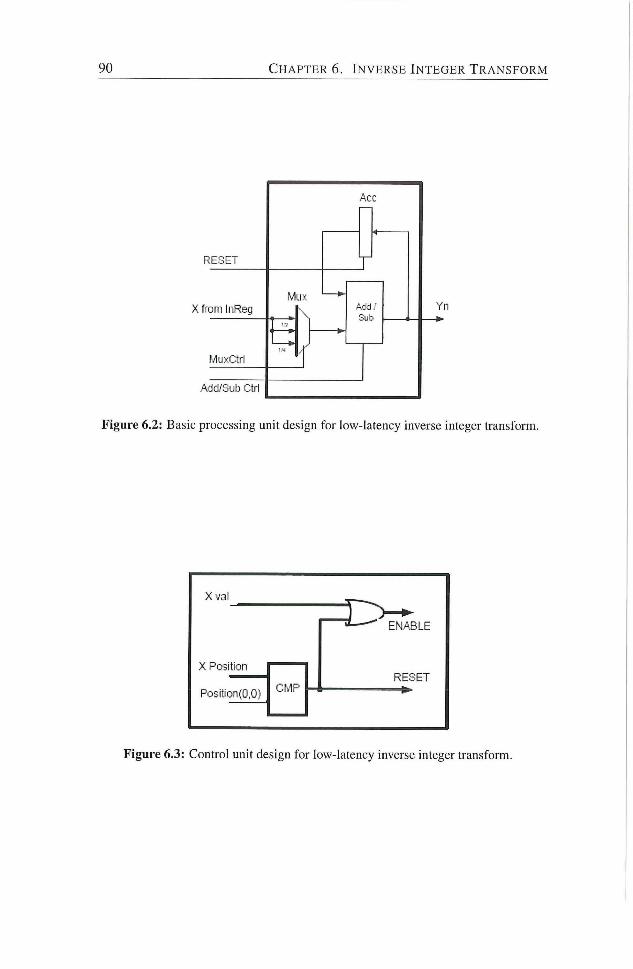
90 C H A P T E R 6 . I N V E R S E I N T E G E R T R A N S F O R M
RESE
X from InReg
Acd/S'jb Ctrl
Figure 6.2: Basic processing unit design for low-latency inverse integer transform.
Xval
ENABLE
X Position
Poslt;on(0,0) CMP RESET
Figure 6.3: Control unit design for low-latency inverse integer transform.
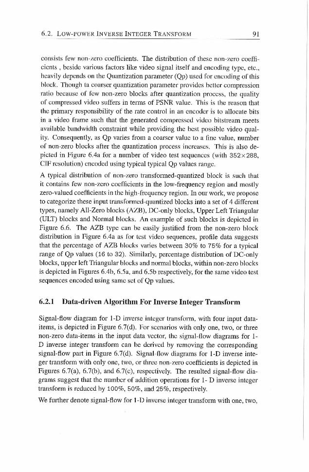
6.2. L O W - P O W E R I N V E R S E I N T E G E R T R A N S F O R M 91
consists few non-zero coefficients. The distribution of these non-zero coeffi
cients , beside various factors hlce video signal itself and encoding type, etc.,
heavily depends on the Quantization parameter (Qp) used for encoding of this
block. Though ta coarser quantization parameter provides better compression
ratio because of few non-zero blocks after quantization process, the quality
of compressed video suffers in terms of PSNR value. This is the reason that
the primary responsibihty of the rate control in an encoder is to allocate bits
in a video frame such that the generated compressed video bitstream meets
available bandwidth constraint while providing the best possible video qual
ity. Consequently, as Qp varies f rom a coarser value to a fine value, number
of non-zero blocks after the quantization process increases. This is also de
picted in Figure 6.4a for a number of video test sequences (with 352x288,
CIF resoludon) encoded using typical typical Qp values range.
A typical distribution of non-zero transformed-quantized block is such that
it contains few non-zero coefficients in the low-frequency region and mostly
zero-valued coefficients in the high-frequency region. In our work, we propose
to categorize these input transformed-quandzed blocks into a set of 4 different
types, namely All-Zero blocks (AZB), DC-only blocks. Upper Lef t Triangular
(ULT) blocks and Normal blocks. A n example of such blocks is depicted in
Figure 6.6. The A Z B type can be easily justified f rom the non-zero block
distribudon in Figure 6.4a as for test video sequences, profile data suggests
that the percentage of A Z B blocks varies between 30% to 75% for a typical
range of Qp values (16 to 32). Similarly, percentage distribudon of DC-only
blocks, upper left Triangular blocks and normal blocks, within non-zero blocks
is depicted in Figures 6.4b, 6.5a, and 6.5b respectively, for the same video test
sequences encoded using same set of Qp values.
6.2.1 Data-driven Algorithm For Inverse Integer Transform
Signal-flow diagram for 1-D inverse integer transform, with four input data-
items, is depicted in Figure 6.7(d). For scenarios with only one, two, or three
non-zero data-items in the input data vector, the signal-flow diagrams for 1-
D inverse integer transform can be derived by removing the corresponding
signal-flow part in Figure 6.7(d). Signal-flow diagrams for 1-D inverse inte
ger transform with only one, two, or three non-zero coefficients is depicted in
Figures 6.7(a), 6.7(b), and 6.7(c), respectively. The residted signal-flow dia
grams suggest that the number of addition operations for 1- D inverse integer
transform is reduced by 100%, 50%, and 25%, respectively.
We further denote signal-flow for 1-D inverse integer transfonn with one, two.

92 C H A P T E R 6. I N V E R S E I N T E G E R T R A N S F O R M
16 20 24 28 32 Qp
(a)
70
• Mobile
16 20 „ 24 28 32 Qp
(b)
Figure 6.4: Percentage distribution of 4x4input block types for inverse integer transform: (a) Non-zero blocks , (b) DC-blocks.
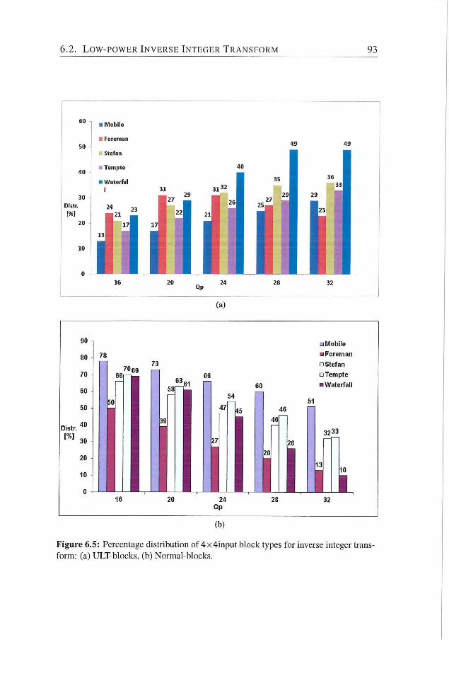
6.2. L O W - P O W E R I N V E R S E I N T E G E R T R A N S F O R M 93
Figure 6.5: Percentage distribution of 4x4input block types for inverse integer transform: (a) ULT-blocks, (b) Normal-blocks.
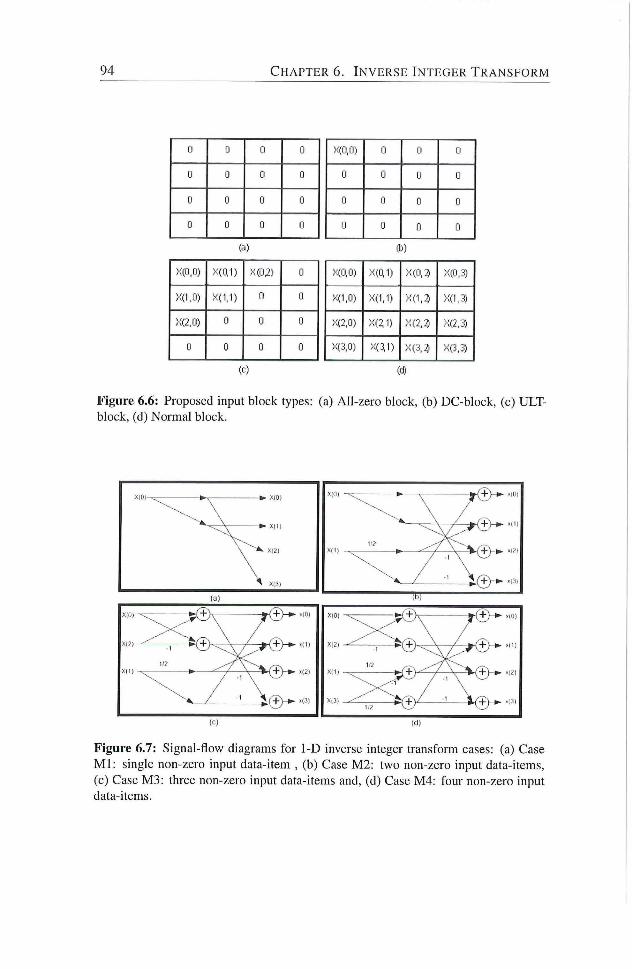
94 C H A P T E R 6. I N V E R S E I N T E G E R T R A N S F O R M
0 Cl 0 0
0 0 0 0
Cl 0 0 0
0 0 0 0
Xffl.O) XCQl) X(02) 0
>;(i.o) X(l,l) 0 0
XG.O) ! 0 0
0 0 0 0
('-)
X(0,0) 0 0 0
0 0 0
0 0 0 0
0 0 0 0
X(0,0) X(CI1) X(0,2i X(P,3)
X(1,0) X(1,1) X(1,^ X(l,3)
X(2,0) XG1) X(2.3 ;<(2,3)
X(3,0) X«1) X(3,^ X(j,3)
(if)
Figure 6.6: Proposed input block types: (a) All-zero block, (b) DC-block, (c) ULT-block, (d) Normal block.
(c) (d)
Figure 6.7: Signal-flow diagrams for 1-D inverse integer transform cases: (a) Case M l : single non-zero input data-item , (b) Case M2: two non-zero input data-items, (c) Case M3: three non-zero input data-items and, (d) Case M4: four non-zero input data-items.
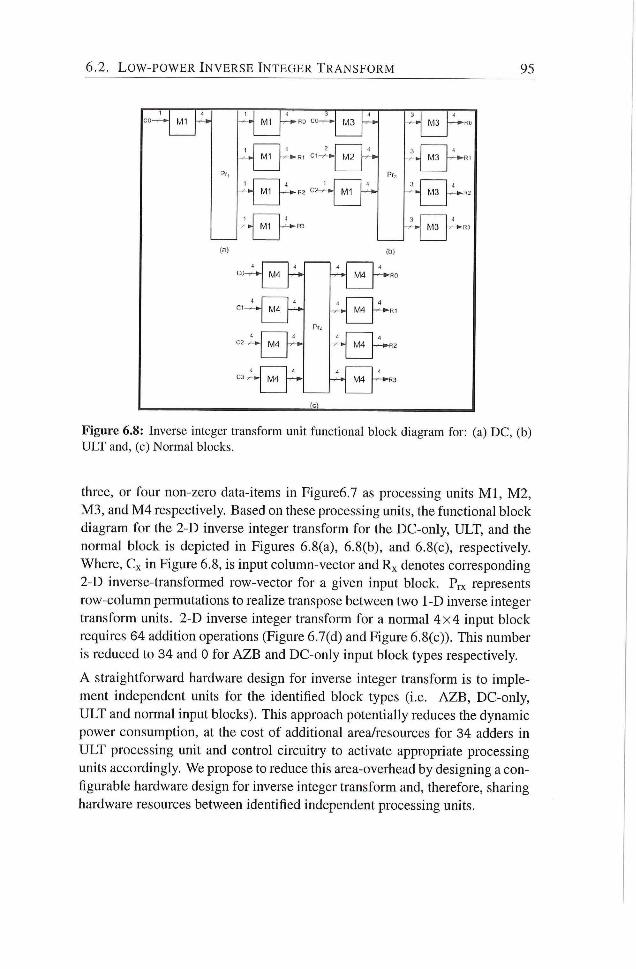
6.2. L O W - P O W E R I N V E R S E I N T E G E R T R A N S F O R M 95
M l M1
Ml
(a)
M4
M4
(v'13
4
M1
4 • f M3
3 4
M:i
-y- ^ M3
3
M3
M 4
^44
M4
Figure 6.8: Inverse integer transform unit functional block diagram for: (a) D C , (b) U L T and, (c) Normal blocks.
three, or four non-zero data-items in Figure6.7 as processing units M l , M 2 ,
M 3 , and M 4 respectively. Based on these processing units, the functional block
diagram for the 2-D inverse integer transform for the DC-only, ULT, and the
normal block is depicted in Figures 6.8(a), 6.8(b), and 6.8(c), respectively.
Where, Cx in Figure 6.8, is input column-vector and Rx denotes corresponding
2-D inverse-transformed row-vector for a given input block. Prx represents
row-column permutations to realize transpose between two 1-D inverse integer
transform units. 2-D inverse integer transform for a normal 4 x 4 input block
requires 64 addition operadons (Figure 6.7(d) and Figure 6.8(c)). This number
is reduced to 34 and 0 for A Z B and DC-only input block types respectively.
A straightforward hardware design for inverse integer transform is to imple
ment independent units for the idendfied block types (i.e. A Z B , DC-only,
ULT and normal input blocks). This approach potentially reduces the dynamic
power consumption, at the cost of additional area/resources for 34 adders in
ULT processing unit and control circuitry to activate appropriate processing
units accordingly. We propose to reduce this area-overhead by designing a con
figurable hardware design for inverse integer transform and, therefore, sharing
hardware resources between identified independent processing units.
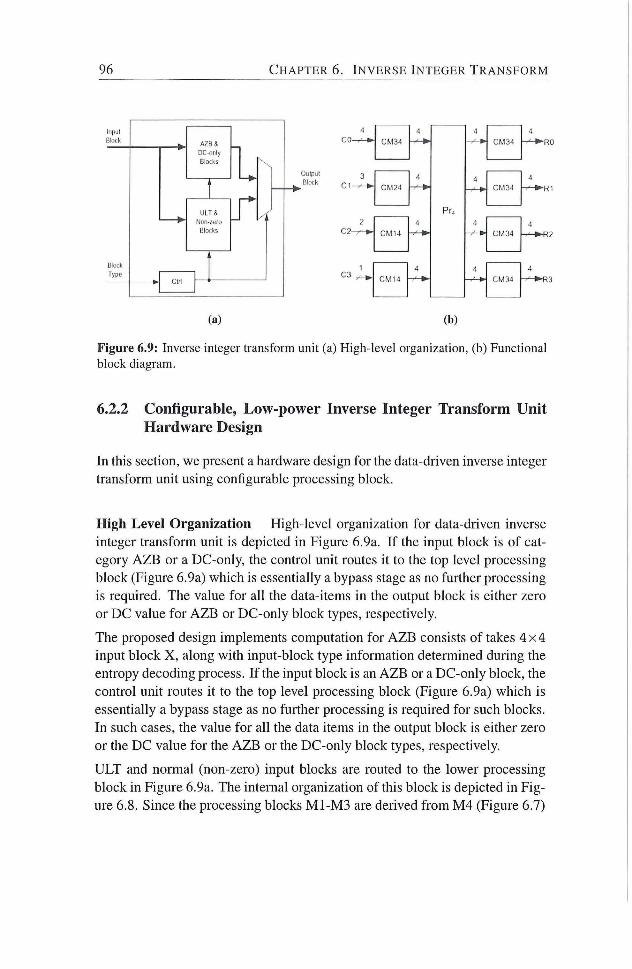
96 C H A P T E R 6. I N V E R S E I N T E G E R T R A N S F O R M
1
BliXk
Type
A Z B S
Blocks
U I T S
Blocks
CM34
Oiilpul
Block 3
C2-
CM34
4
«J CM34
(a) (b)
Figure 6.9: Inverse integer transform unit (a) High-level organization, (b) Functional block diagram.
6,2,2 Configurable, Low-power Inverse Integer Transform Unit Hardware Design
In this section, we present a hardware design for the data-driven inverse integer
transform unit using configurable processing block.
High Level Organization High-level organization for data-driven inverse
integer transform unit is depicted in Figure 6.9a. I f the input block is of cat
egory A Z B or a DC-only, the control unit routes it to the top level processing
block (Figure 6.9a) which is essendally a bypass stage as no further processing
is required. The value for all the data-items in the output block is either zero
or DC value for A Z B or DC-only block types, respectively.
The proposed design implements computadon for A Z B consists of takes 4 x 4
input block X , along with input-block type informadon determined during the
entropy decoding process. I f the input block is an A Z B or a DC-only block, the
control unit routes it to the top level processing block (Figure 6.9a) which is
essentially a bypass stage as no further processing is required for such blocks.
In such cases, the value for all the data items in the output block is either zero
or the DC value for the A Z B or the DC-only block types, respectively.
ULT and normal (non-zero) input blocks are routed to the lower processing
block in Figure 6.9a. The internal organization of this block is depicted in Fig
ure 6.8. Since the processing blocks M1-M3 are deiived f rom M 4 (Figure 6.7)
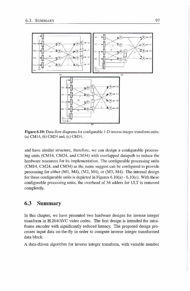
6.3. S U M M A R Y 97
Figure 6.10: Data-flow diagrams for configurable 1-D inverse integer transform units: (a) CM 14, (b) CM24 and, (c) CM34.
and have similar structure, therefore, we can design a configurable process
ing units ( C M 14, CM24, and CM34) with overlapped datapath to reduce the
hardware resources for its implementadon. The configurable processing units
(CM14, CM24, and CM34) as the name suggest can be configured to provide
processing for either ( M l , M4) , (M2, M4) , or (M3, M4) . The intemal design
for these configurable units is depicted in Figures 6.10(a) - 6.10(c). With these
configurable processing units, the overhead of 34 adders for ULT is removed
completely.
6.3 Summary
In this chapter, we have presented two hardware designs for inverse integer
transform in H.264/AVC video codec. The first design is intended for intra-
frame encoder with significantly reduced latency. The proposed design pro
cesses input data on-the-fly in order to compute inverse integer transformed
data block.
A data-driven algorithm for inverse integer transform, with variable number
98 C H A P T E R 6. I N V E R S E I N T E G E R T R A N S F O R M
of operations, is also introduced in this chapter The proposed hardware de-
sign,based on data-driven algorithm, provides high-throughput and consumes
significantly less dynamic power for its implementation. The area-overhead of
inverse integer transform unit is reduced by designing a configurable hardware
and efficiently sharing hardware resources between independent processing
units.
Note.
The content of this chapter is based on the the fol lowing papers:
Muhammad Nadeem, Stephan Wong, and Georgi Kuzmanov, Inverse Integer
Transform in H.264/AVC Intra-frame Encoder, proceedings of Intemational
Symposium on Electronic Design, Test and Applicadon 2011 (DELTA), pp.
228-233, Queens town. New Zealand, lanuary 2011.
Muhammad Nadeem, Stephan Wong, and Georgi Kuzmanov, Configurable,
Low-power design for Inverse Integer Transform in H.264/AVC, proceedings of
Intemational Conference on Fronders of Informadon Technology 2010 (FIT),
pp. 32-37, Islamabad, Pakistan, December 2010.
7 Custom Operations
PPLlCATlON-specific embedded system design lias become more difficult i ~ \ than ever due to rapid increase in design complexity. Efficiency and
flexibihty must be carefully balanced to meet a number of embedded system
application requirements. Apphcations running on a programmable platform
can be executed either as a software algorithm or a speciahzed hardware unit.
The first approach is slowest one but most flexible. Specialized hardware ap
proach, on the other hand, is the fastest approach but least flexible. From video
processing perspective, flexibility to adapt to video coding standard evoludons
and market/technology induced changes has become a new dimension in the
algorithm/architecture design. Newly emerged reconfigurable and extensible
processors offer a favorable tradeoff between efficiency and flexibility, and
a promising way to minimize certain important metrics (e.g., execudon-time
and code-size, etc.) of embedded processors. Reconfigurable computing has
proven itself to be able to speed-up many apphcations despite its lack in achiev
ing high frequencies. However, frequency is not the sole factor that determines
performance. Field Programmable Gate Arrays (FPGAs) - as most utihzed re
configurable fabric nowadays - provide a large amount of parallel stmctures
those when exploited efficiently greatly contribute to the speedup of applica
dons. Therefore, reconfigurable computing could possibly be the soludon to
provide needed flexibility along with performance.
With high-performance computing point of view, a custom instraction in a pro
cessor is an assembly operadon that implements functionality of a compute-
intensive kernel of an application for its accelerated performance. Tradition
ally, custom operations have already been used in commercial Complex In
stracdon Set Computers (CISC) and Dighal Signal Processors (DSP) to ac
commodate operadons that consist of more complexity; operadons such as
floadng point or complex arithmedc operadons. By extending instracdon set
with a more complex operation, fewer operations are needed to achieve the
99
100 C H A P T E R 7. C U S T O M O P E R A T I O N S
same result leading to a more compact set of operations in an application with
potentially faster execution time as a result. From efficient and flexible video
processing perspective, we propose to incorporate a customized functional unit
in the datapath of reconfigurable, soft-core, V L I W processor for compute in
tensive functions in H.264/AVC video codec. More specifically, main contri
butions are provided as fohows:
1. A proposal to extend ISA of p - V E X reconfigurable, soft-core, V L I W
processor with an apphcation-specific custom-operations.
2. Designs for various compute-intensive operations in H.264/AVC video
codec and their implementadon in p - V E X datapath.
The chapter is organized as follows: In Section 7.1, we provide an overview of
proposed customized funcdonal unit in p -VEX, soft-core V L I W processor. A
number of custom-operadons for compute-intensive functions in H.264/AVC
are presented in Secdon 7.2. Finally, Secdon 7.3 provides summary of this
chapter
7.1 p - \ E X : Customized VLIW Soft-core Processor
Digital video signal processing applicadons are identified to have significant
fine and coarse-grained parallelism [13] Therefore, Very Long Instmction
Word ( V L I W ) processors are preferred computing platform for such appli
cations to achieve high performance [14]. V L I W processors exploit existing
parallehsm in video processing applications in order to provide improved per
formance by utilizing pipehning and multiple funcdonal units (FUs) to execute
several operations simultaneously. For a moderate cost, the peiformance of
V L I W processors can be further improved. p - V E X is an open source, extensi
ble, and reconfigurable, soft-core V L I W processor We propose to incorporate
a customized functional unit in the datapath of p - V E X V L I W processor. This
customized funcdonal unit implements applicadon-specific custom instmction
for compute-intensive functions in video codec H.264/AVC.
The top-level functional blocks in the five-stage pipeline of p -VEX along wi th
Custom Functional Unit (CFU) is depicted in Figure 7.1. The ISA of V E X
processor is extendable. CFU implements new applicadon-specific custom-
operations with a latency of 2 cycles. The CFU is part of Execution stages
(Exec.1 and Exec. 2) in the pipeline of p - V E X processor and interfaces wi th
Decode and WriteBack stages as depicted in Figure 7.1. The custom funcdonal
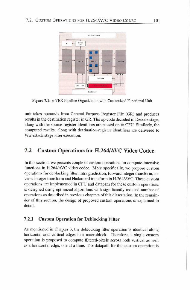
7 .2 . C U S T O M O P E R A T I O N S FOR H . 2 6 4 / A V C V I D E O C O D E C 101
Figure 7.1: p-VEX Pipeline Organization with Customized Functional Unit
unit takes operands f rom General-Purpose Register File (GR) and produces
resuhs in the destination register in GR. The op-code decoded in Decode stage,
along with the source-register identifiers are passed on to CFU. Similarly, the
computed results, along with destination-register identifiers are dehvered to
WriteBack stage after execution.
7.2 Custom Operations for H.264/AVC Video Codec
In this section, we presents couple of custom operations for compute-intensive
functions in H.264/AVC video codec. More specifically, we propose custom
operations for deblocking filter, intra prediction, forward integer transform, in
verse integer transform and Hadamard transform in H,264/AVC. These custom
operadons are implemented in CFU and datapath for these custom operations
is designed using opdmized algorithms with significantly reduced number of
operations as described in previous chapters of this dissertation. In the remain
der of this secdon, the design of proposed custom operadons is explained in
detail.
7.2.1 Custom Operation for Deblocking Filter
As mentioned in Chapter 3, the deblocking filter operation is identical along
horizontal and verdcal edges in a macroblock. Therefore, a single custom
operadon is proposed to compute filtered-pixels across both vertical as weh
as a horizontal edge, one at a time. The datapath for this custom operation is
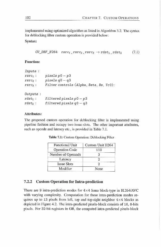
102 C H A P T E R 7. C U S T O M O P E R A T I O N S
implemented using optimized algorithm as hsted in Algorithm 3.2. The syntax
for deblocking filter custom operadon is provided below:
Syntax:
CU_DBF_H264: r s r c i , r s r c s , r s r c g ^ r d s t i ^ r d s t j (7.1)
Function:
I n p u t s :
rsrci : pixels pO — p3
rsrc2 • pixels qO — qS
rsrc3 : Filter controls (Alpha, Beta, Bs, TcO):
Outputs :
rdsti : filtered pixels pO — p3
r d s t g : f i l t e r e d p i x e l s qO — q3
Attributes:
The proposed custom operation for deblocking filter is implemented using
pipehne fashion and occupy two issue-slots. The other important attributes,
such as opcode and latency etc., is provided in Table 7.1.
Table 7.1: Custom Operation: Deblocking Filter
Functional Unit Custom Unit H264
Operation Code 110
Number of Operands 3
Latency 2
Issue Slots 2
Modifier None
7.2.2 Custom Operation for Intra-prediction
There are 9 intra-predicdon modes for 4 x 4 luma block-type in H.264/AVC
with varying complexity. Computation for these intra-prediction modes re
quires up to 13 pixels f rom left, top and top-right neighbor 4 x 4 blocks as
depicted in Figure 4.2. The intra-predicted pixels-block consists of 16, 8-bits
pixels. For 32-bit registers in GR, the computed intra-predicted pixels-block
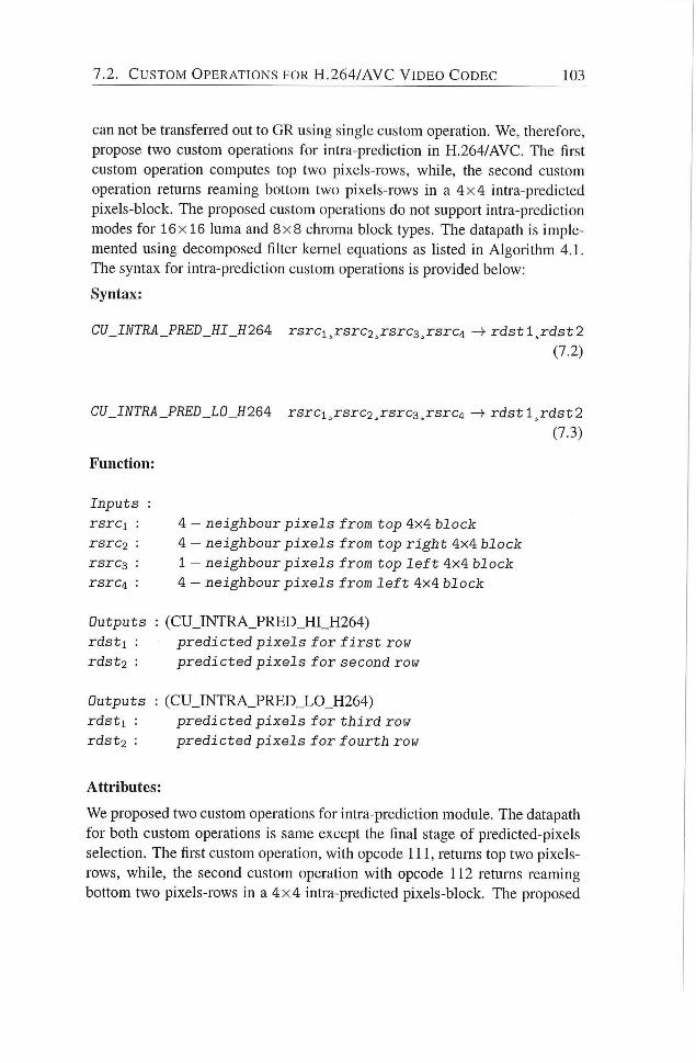
7 . 2 . C U S T O M O P E R A T I O N S FOR H . 2 6 4 / A V C V I D E O C O D E C 103
can not be transferred out to GR using single custom operation. We, therefore,
propose two custom operations for intra-prediction in H.264/AVC. The first
custom operation computes top two pixels-rows, while, the second custom
operation returns reaming bottom two pixels-rows in a 4 x 4 intra-predicted
pixels-block. The proposed custom operations do not support intra-prediction
modes for 16x 16 luma and 8 x 8 chroma block types. The datapath is imple
mented using decomposed filter kernel equations as listed in Algori thm 4.1.
The syntax for intra-prediction custom operations is provided below:
Syntax:
CU_INTRA_PRED_HI_H26A rsrci^rsrc2,rsrc3^rsrcA ^ r d s t l ^ r d s t 2
(7.2)
CU_INTRA_PRED_L0_H26A rsrci^rsrc2,rsrc3^rsrcA
Function:
r d s t l ^ r d s t 2
(7.3)
Inputs :
rsrci : A — neighbour pixels from top AxA block
rsrc2 : 4 — ne ighbour pixels from top right 4x4 block
rsrc3 : 1 - neighbour pixels from top l e f t 4x4 block
rsrcA : 4 - ne ighbour pixels from l e f t 4x4 blocJc
Outputs : (CUJNTRA_PRED_HI_H264)
r d s t i : p r e d i c t e d pixels for f i r s t row
rdst2 • predicted pixels for second row
Outputs : (CU_INTRA_PRED_LO_H264)
r d s t i : predicted pixels for third row
rdst2 : predicted pixels for fourth row
Attributes:
We proposed two custom operations for intra-prediction module. The datapath
for both custom operadons is same except the final stage of predicted-pixels
selecdon. The first custom operadon, with opcode 111, returns top two pixels-
rows, while, the second custom operadon with opcode 112 returns reaming
bottom two pixels-rows in a 4 x 4 intra-predicted pixels-block. The proposed
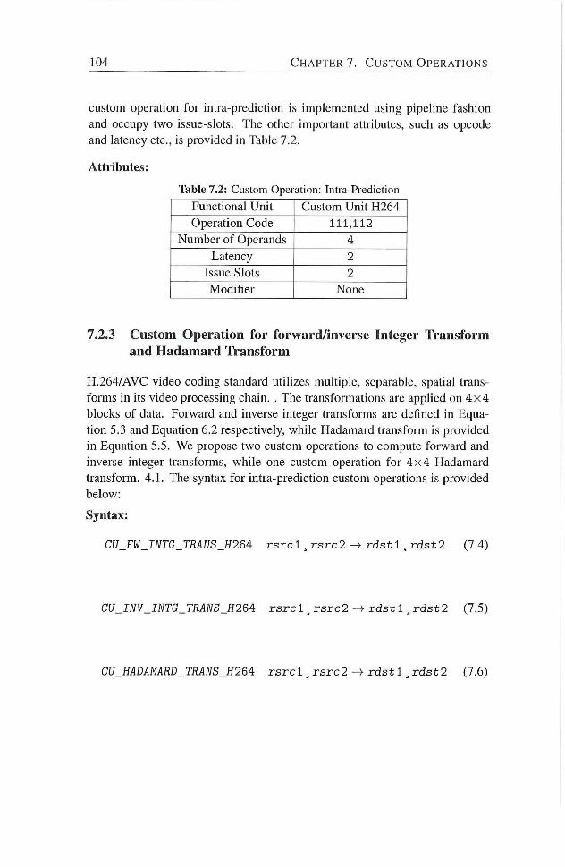
104 C H A P T E R 7 . C U S T O M O P E R A T I O N S
custom operation for intra-prediction is implemented using pipeline fashion
and occupy two issue-slots. The other important ahributes, such as opcode
and latency etc., is provided in Table 7.2.
Attributes:
Table 7.2: Custom Operation: Intra-Prediction
Functional Unit Custom Unit H264
Operation Code 111,112
Number of Operands 4
Latency 2
Issue Slots 2
Modifier None
7.2.3 Custom Operation for forward/inverse Integer Transform and Hadamard Transform
H.264/AVC video coding standard utilizes multiple, separable, spatial trans
forms in its video processing chain. . The transformations are applied on 4 x 4
blocks of data. Forward and inverse integer transforms are defined in Equa
tion 5.3 and Equadon 6.2 respectively, while Hadamard transform is provided
in Equadon 5.5. We propose two custom operations to compute forward and
inverse integer transforms, while one custom operadon for 4 x 4 Hadamard
transform. 4.1. The syntax for intra-predicdon custom operations is provided
below:
Syntax:
CU_FW_INTG_TRANS_H264: rsrc 1 ^ rsrc 2 -> r d s t 1 , r d s t 2 (7.4)
CU_INV_INTG_TRANS_H26A rsrc 1 , r s r c 2 r d s t 1 , r d s t 2 (7.5)
CU_HADAMARD_TRANS_H26A rsrc 1 ^ r s r c 2 -> r d s t 1 , r d s t 2 (7.6)
7.3. S U M M A R Y 105
Function:
I n p u t s
r s r c i :
rsrc2 :
[ X Q X I ] elements o f 4 x 1 i n p u t vector
[ x 2 X 3 ] e lements o f 4 x 1 i n p u t v e c t o r
Outputs :
r d s t i :
r d s t o :
[yoy i ] ( f o r w a r d / i n v e r s e , H a d a m a r d ) transformed
elements o f 4 x 1 o u t p u t v e c t o r
[y2y3] ( f o r w a r d / i n v e r s e , H a d a m a r d ) transformed
elements o f 4 x 1 o u t p u t v e c t o r
Attributes:
The opcode 113 and 114 are assigned to 1 -D forward and inverse integer trans
form custom operations respectively. While, opcode 115 is assigned to 1-D
Hadamard transform custom operation. The proposed custom operation for
transform is also implemented using pipeline fashion and occupy two issue-
slots. The other important attributes, such as opcode and latency etc., is pro
vided in Table 7.3.
Table 7.3: Custom Operation: Transform Unit
Functional Unit Custom Unit H264
Operation Code 113,114, 115
Number of Operands 2
Latency 2
Issue Slots 2
Modifier None
7.3 Summary
In this chapter, we have proposed to incorporate a customized functional unit in
the datapath of reconfigurable, soft-core V L I W (p -VEX) processor. The pro
posed customized functional unit implements custom operations for compute-
intensive processing functions in video codec H.264/AVC. More specifically,
we propose one custom operation for deblocking filter, two custom operadons
to compute 9 intra-prediction modes for 4 x 4 luma pixels-block, two custom
operations for forward, inverse integer transform pair, and one custom opera-
don to compute 4 x 4 Hadamard transform. Datapath for these custom opera-
1 0 6 C H A P T E R 7 . C U S T O M O P E R A T I O N S
tions are implemented using coiTesponding optimized algorithms with signif
icantly reduced complexity as presented in previous chapters of this disserta
tion.
Note.
The content of this chapter is based on the the following paper:
Muhammad Nadeem, Fakliar Anjam, and Stephan Wong, Application Spe
cific Custom Operations for H.264/AVC on p-VEX: A Reconfigurable Soft-core
VLIW Processor., <To be submitted>.
8 Experimental Results
ADVANCES in video compression standards continue to enable high-end
video applicadons (for instance video conferencing/video calls, personal
video recording, digital TV, internet video streaming, etc.) with better video
quality, higher video resolutions, and lower bit-rates. The reahzation of ad
vanced video coding with high-resoludon videos on battery-powered mobile
devices demands high complexity reducdon in video coding algorithms for
their real-dme and low-power implementadon. Consequendy, the main objec
tives of this dissertadon are to investigate how to achieve high-performance
for real-time video processing apphcations in terms of throughput while utiliz
ing less on-chip resources. Similarly, this dissertation also proposes adaptive,
low-power hardware design for multimedia video compression apphcations on
battery-powered electronic devices without compromising the video quality.
In previous chapters of this dissertation, we have presented several different de
signs for compute-intensive processing functions in H.264/AVC video codec.
For experimental evaluation , the proposed design are described in V H D L and
various parameters such as throughput, area-cost, and dynamic power con
sumption are computed using a number of typical test video sequences. . This
chapter presents the experimental results and also provides a comparison of
proposed hardware designs with sate-of-the-ait already presented in the litera
ture. The concluding remarks are provided at the end of this chapter.
8.1 Deblocking Filter
Deblocking filter is one of the top three compute intensive functions in
H.264/AVC video codec. In Chapter 3, we have presented two hardware
designs for deblocking fiher. Both of these hardware designs as based on
optimized deblokcing filter algorithm with significantly reduced complexity
107
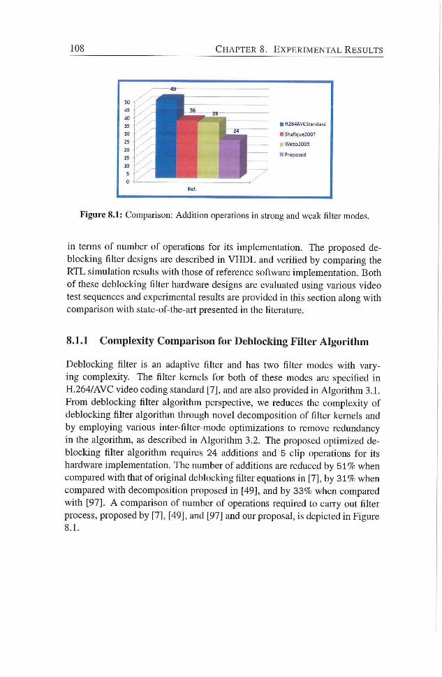
108 C H A P T E R 8. E X P E R I M E N T A L R E S U L T S
• H2HAVCSanclstd
• 5haFH,ue2007
Wthh2003
• Proposed
Ref.
Figure 8.1: Comparison: Addition operations in strong and weak filter modes.
in terms of number of operations for its implementation. The proposed de
blocking filter designs are described in V H D L and verified by comparing the
RTL simulation results with those of reference software implementation. Both
of these deblocking filter hardware designs are evaluated using various video
test sequences and experimental results are provided in this section along with
comparison with state-of-the-art presented in the literature.
8.1.1 Complexity Comparison for Deblocking Filter Algorithm
Deblocking filter is an adaptive filter and has two filter modes with vary
ing complexity. The filter kernels for both of these modes are specified in
H.264/AVC video coding standard [7], and are also provided in Algorithm 3.1.
From deblocking filter algorithm perspective, we reduces the complexity of
deblocking filter algorithm through novel decomposition of fiher kernels and
by employing various inter-filter-mode optimizations to remove redundancy
in the algorithm, as described in Algori thm 3.2. The proposed opdmized de
blocking filter algorithm requires 24 additions and 5 clip operadons for its
hardware implementation. The number of additions are reduced by 5 1 % when
compared with that of original deblocking fiker equations in [7], by 3 1 % when
compared with decomposidon proposed in [49], and by 33% when compared
with [97]. A comparison of number of operations required to caiTy out filter
process, proposed by [7], [49], and [97] and our proposal, is depicted in Figure
8.1.
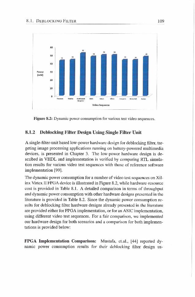
8.1. D E B L O C K I N G F I L T E R 109
Power 30
(mW)
ForeoMn MoWIe Mothwand Parii Ne us atent Tenpete WaletFall iltfan Daughter
Video Sequence
Figure 8.2: Dynamic power consumption for various test video sequences.
8.1.2 Deblocking Filter Design Using Single Filter Unit
A single-filter-unit based low-power hardware design for deblocking filter, tar
geting image processing applications running on battery-powered multimedia
devices, is presented in Chapter 3. The low-power hardware design is de
scribed in V H D L and implementation is verified by comparing RTL simula
tion results for various video test sequences with those of reference software
implementation [99].
The dynamic power consumption for a number of video test sequences on X i l
inx Virtex I I FPGA device is illustrated in Figure 8.2, while hardware-resource
cost is provided in Table 8.1. A detailed comparison in terms of throughput
and dynamic power consumption with other hardware designs presented in the
literature is provided in Table 8.2. Since the dynamic power consumption re
sults for deblocking filter hardware designs already presented in the literature
are provided either for FPGA implementation, or for an ASIC implementadon,
using different video test sequences. For a fair comparison, we implemented
our hardware design for both scenaiios and a comparison for both implemen
tadons is provided below:
F P G A Implementation Comparison: Mustafa, et.al., [44] reported dy
namic power consumpdon results for their deblocking filter design us-
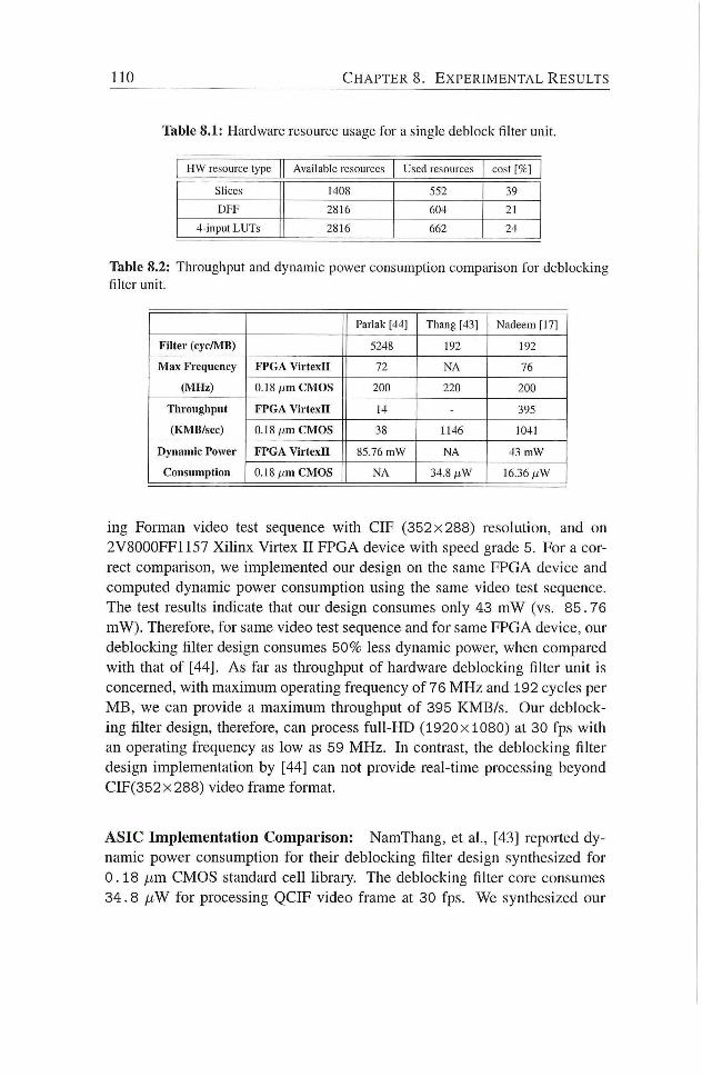
110 C H A P T E R 8. E X P E R I M E N T A L R E S U L T S
Table 8.1: Hardware resource usage for a single deblock filter unit.
ITW resource type Available resources Used resources cost [%]
Slices 1408 552 39
D F F 2816 604 21
4-input L U T s 2816 662 24
Table 8.2: Throughput and dynamic power consumpdon comparison for deblocking filter unit.
Parlak [44] Thang [43] Nadeem [17]
F i l t er ( cyc /MB) 5248 192 192
M a x Frequency
( M H z )
F P G A V i r t e x n 72 NA 76 M a x Frequency
( M H z ) 0.18 AJm C M O S 200 220 200
Tl iroughput
( K M B / s e c )
F P G A V i r t e x n 14 - 395 Tl iroughput
( K M B / s e c ) 0.18/j,m C M O S 38 1146 1041
D y n a m i c Power
Consumption
F P G A V i r t e x n 85.76 m W N A 43 m W D y n a m i c Power
Consumption 0.18 p m C M O S N A 34.8 /J.W 16.36/.tW
ing Eorman video test sequence with CIE (352x288) resolution, and on
2V8000FE1157 Xihnx Virtex I I FPGA device with speed grade 5. For a cor
rect comparison, we implemented our design on the same FPGA device and
computed dynamic power consumpdon using the same video test sequence.
The test results indicate that our design consumes only 43 m W (vs. 85.76
mW). Therefore, for same video test sequence and for same FPGA device, our
deblocking filter design consumes 50% less dynamic power, when compared
with that of [44]. As far as throughput of hardware deblocking filter unit is
concerned, with maximum operating frequency of 76 M H z and 192 cycles per
M B , we can provide a maximuin throughput of 395 KMB/s . Our deblock
ing filter design, therefore, can process f u l l - H D (1920x1080) at 30 fps with
an operating frequency as low as 59 MHz . In contrast, the deblocking filter
design implementation by [44] can not provide real-time processing beyond
CIF(352x288) video frame format.
A S I C Implementation Comparison: NamThang, et al., [43] reported dy
namic power consumption for their deblocking filter design synthesized for
0 .18 fim CMOS standard cell hbrary. The deblocking filter core consumes
34 .8 jiW for processing QCIF video frame at 30 fps. We synthesized our
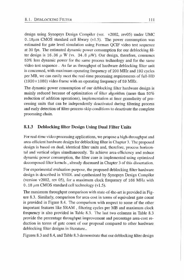
8.1. D E B L O C K I N G F I L T E R 111
design using Synopsys Design Compiler (ver. v2002, rev05) under U M C
0 .18pm CMOS standard cell library (v l .5) . The power consumption was
estimated for gate level simulation using Forman QCIF video test sequence
at 30 fps. The estimated dynamic power consumption for our deblocking h l
ter design is 16.36 p W (vs. 34 .8 p W ) . Our design, therefore, consumes
53% less dynamic power for the same process technology and for the same
video test sequence . As far as throughput of hardware deblocking filter unit
is concemed, with maximum operating frequency of 200 M H z and 192 cycles
per M B , we can easily meet the real-time processing requirements of f u l l - H D
(1920 X1080) video frame with an operating frequency of 59 MHz.
The dynamic power consumption of our deblocking filter hardware design is
mainly reduced because of opdmizadon of filter algorithm (more than 50%
reducdon of addhion operadons), implementadon at finer granularity of pro
cessing units that can be independently deactivated during filtering process
and early detecdon of filter-process-skip conditions to deactivate the complete
processing chain.
8.1.3 Deblocking filter Design Using Dual Filter Units
For real-dme video processing apphcadons, we propose a high-throughput and
area-efficient hardware design for deblocking filter in Chapter 3. The proposed
design is based on dual, idendcal filter units and, therefore, process horizon
tal and vertical edges simultaneously. To achieve area-efficiency and reduce
dynamic power consumpdon, the filter core is implemented using opdmized
decomposed filter kernels , already discussed in Chapter 3 of this dissertation.
For experimental evaluation purpose, the proposed deblocking filter hardware
design is described in V H D L and synthesized by Synopsys Design Compiler
(version v2002, rev 05), for a maximum clock frequency of 166 M H z with
0 .18 p m CMOS standard ceU technology (v l .5) .
The maximum throughput comparison with state-of-the-art is provided in Fig
ure 8.3. Similarly, comparison for area-cost in terms of equivalent gate count
is provided in Figure 8.4. The comparison with respect to some of the other
important features like S R A M , filtering cycles per M B and maximum clock
frequency is also provided in Table 8.3. The last two columns in Table 8.3
provide the percentage throughput improvement and percentage area-cost re
duction in terms of gate count of our proposal compared to other hardware
deblocking filter designs in hterature..
Figures 8.3 and 8.4, and Table 8.3 demonstrate that our deblocking filter design
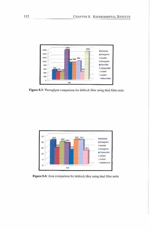
112 C H A P T E R S . E X P E R I M E N T A L R E S U L T S
• shihzoos
• Zhen|2<>04
U ÜU20O5
• chengzoos
• T0b3jas2Q011
KU2003
UU20O7
Hadeeni2010
Figure 8.4: Area comparison for deblock filter using dual filter units
8.2. I N T R A P R E D I C T I O N 113
provides much higher throughput on one hand and requires signihcantly less
area for its implementation on the other
The comparisons with [48] and [27] need some clarihcation. The design by
[48] requires almost the same area as ours, however, we provide 63% higher
throughput. While on the other hand, reference [27] provides almost the same
throughput as we do, however, we require 35% less area in terms of equivalent
gates for its implementation.
The higher throughput of our design is achieved by merging the processing
elements on the critical path and making it shorter. The area reduction, on the
other hand, is mainly achieved because of:
• Algorithm level optimization - through decomposition of the filter kernels,
inter-filter-mode optimizations and overlapped datapaths, we are able to reduce
the number of additions by 5 1 % and, therefore, reduce the combinatorial logic
for the implementation;
• Hardware design level optimization - through efficient pipehne stage design
we reduce the number of registers required for intermediate resuhs for the
next pipeline stage, reuse the same hardware resource for the realization of
transpose units by identification of mutual exclusive operations in processing
chain.
From the comparison with other designs presented in Table 8.3, we suggest
that the proposed hardware accelerator requires 17%-44% less area in teims of
equivalent gate count on one hand and provides up to 271% higher throughput
on the other The designs by [38], [31], [56], though require less area in terms
of equivalent gate count. However, this is not a fair comparison as these three
designs do not include the logic for the boundary strength computation, where
as, our design includes the boundary strength computadon unit. As far as the
throughput is concemed, the proposed hardware design is 24% better when
compared with [38] having highest throughput among [38], [31], [56].
8.2 Intra Prediction
In Chapter 4, we have presented a high-throughput and area-efficient hard
ware design for intra-prediction in H.264/AVC. The proposed design sup
ports 4 intra-prediction modes for luma 16x16 pixels-block type, 4 intra-
prediction modes for chroma 8 x 8 pixels-block type, and 9 intra-prediction
modes fo r 4 x 4 pixels-block type in H.264/AVC. The hardware design for
intra-prediction unit is based on optimized algorithm with reduced complexity
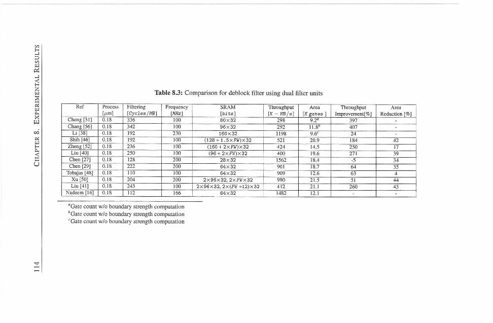
C/5
ir.
<
w Table 8.3: Comparison for deblock filter using dual filter units
X
Ref Process Filtering Frequency S R A M Throughput Area Throughput Area [/jm] [Cycles/MB] [MHz] [ b i t s ] [K - MB/s] [K g a t e s ] Improvement[%] Reduction [%]
Cheng [31] 0.18 336 too 8 0 x 3 2 298 9.2" 397 -
Chang [56] 0.18 342 too 9 6 x 3 2 292 11.8" 407 -
L i [38] 0.18 192 230 1 6 0 x 3 2 1198 9.6'' 24 -
Shih [46] 0.18 192 100 (128 + 1 .5XF1 / )X32 521 20.9 184 42 Zheng [52] 0.18 236 100 (160 + 2 x F W ) x 3 2 424 14.5 250 17
L i u [40] 0.18 250 100 (96 + 2 X F J / ) X 3 2 400 19.6 271 39 Chen [27] 0.18 128 200 2 8 X 3 2 1562 18.4 -5 34 Chen [29] 0.18 222 200 6 4 X 3 2 901 18.7 64 35
Tobajas [48] 0.18 n o too 64X32 909 12.6 63 4 X u [50] 0.18 204 200 2 x 9 6 x 3 2 . 2 X F I / X 3 2 980 21.5 51 44 L i u [41] 0.18 243 100 2 X 9 6 X 3 2 , 2x(Fil + 1 2 ) x 3 2 412 21.1 260 43
Nadeem [16] 0.18 112 166 6 4 X 3 2 1482 12.1 - -
"Gate count w/o boundary strength computation 'Gate count w/o boundary strength computation ' Gate count w/o boundary strength computation
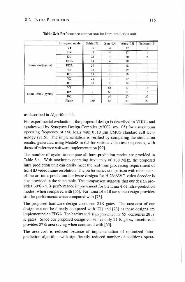
8.2. I N T R A P R E D I C T I O N 115
Table 8.4: Performance comparison for Intra-prediction unit.
Intra-pred mode Sahin [71] X u n [65] Wang [73] Nadeem [18]
V T 17 4 17 1
H Z 17 4 17 1
D C 21 4 20
D D L 24 4 18 1
L u m a 4x4 [cycles] D D R 24 4 18 1
V R 23 4 19 1
H D 23 4 19 1
V L 22 4 19 1
H U 20 4 18 1
V T - 66 17 16
L u m a 16x16 [cycles] H Z - 66 17 16
L u m a 16x16 [cycles] D C - 66 20 22
Plane 340 66 20 22
as described in Algorithm 4.1.
For experimental evaluation , the proposed design is described in V H D L and
synthesized by Synopsys Design Compiler (v2002, rev. 05) for a maximum
operating frequency of 150 M H z with 0.18 jim CMOS standard ceh tech
nology (v l .5 ) . The implementadon is verified by comparing the simulation
results, generated using ModelSim 6.5 for various video test sequences, with
those of reference software implementation [99].
The number of cycles to compute all intra-prediction modes are provided in
Table 8.4. With maximum operating frequency of 150 MHz, the proposed
intra prediction unit can easily meet the real-time processing requirement of
f u l l - H D video frame resoludon. The performance comparison with other state-
of-the-art intra-predicdon hardware designs for H.264/AVC video decoder is
also provided in the same table. The comparison suggests that our design pro
vides 50% -75% performance improvement for the luma 4 x 4 intra-prediction
modes, when compared with [65], For luma 16x 16 case, our design provides
similar peiformance when compared with [73].
The proposed hardware design consumes 2 I K gates. The area-cost of our
design can not be directly compared with [71] and [73] as these designs are
implemented on FPGA. The hardware design presented in [65] consumes 28 .7
K gates. Since our proposed design consumes only 21 K gates, therefore, it
provides 27% area saving when compared with [65].
The area-cost is reduced because of implementadon of optimized intra-
prediction algorithm with significantly reduced number of additions opera-
116 C H A P T E R S . E X P E R I M E N T A L R E S U L T S
tions (27-60% reduction). Moreover, overlapped datapath for 4 x 4 ,8x8 , and
16x16 pixels-block types also helps to greatly reduce area-cost for hardware
implementation of intra-prediction unit.
8.3 Forward Integer Transform
In Chapter 5, we have presented two solutions for realization of integer trans
form in the processing chain of intra-frame encoder applications. The first
soludon targets image compression apphcations i-unning on battery-powered
electronic devices, such as digital still camera. The proposed solution utilizes
a novel 2-D transform to derive integer-transformed coefficients directly f rom
that of Hadamard-transformed coefficients with significantly reduced number
of operadons and, therefore, area and power consumpdon. The second solu
don targets real-time video compression apphcations using intra-frames only.
The proposed solution reduces the effective latency penalty of forward integer
transform to zero. Moreover, i t aggressively reuses the intermediate results
f rom Hadamard transform and, therefore, requires significantly reduced num
ber of operations and, thus, less area for its hardware implementation
Both of the hardware designs for realization of integer transform are evaluated
experimentally by describing them V H D L and synthesized using Synopsys
Design Compiler (v2002 rev05) under 0.18 //m CMOS standard cell library
(v l .5 ) . The implementation for these designs, was verified, as useual, by com
paring the simulation results for a set of video test sequences with those of ref
erence software implementation [99]. The maximum operating frequency for
synthesized design is 200 MHz. After logic synthesis, the dynamic power con
sumption was estimated using Synopsys Pr imePower™. Experimental evalu
ation of proposed designs is provided as follows:
8.3.1 Forward Integer Transform for Image Processing Applications
The comparison of proposed hardware design for single 4 x 4 integer transform
unit with state-of-the-art is provided in Table 8.5. From the comparison with
other solutions, we suggest that the proposed solution provides the minimum
latency penalty (4 .82 ns) among all solutions in Table 8.5. and also requires
significantly less area (2 . 6K gates) in terms of equivalent gate count for its
hardware implementation. Therefore, i t provides up to 5 times better perfor
mance in terms of throughput/area ratio for the same process technology. This
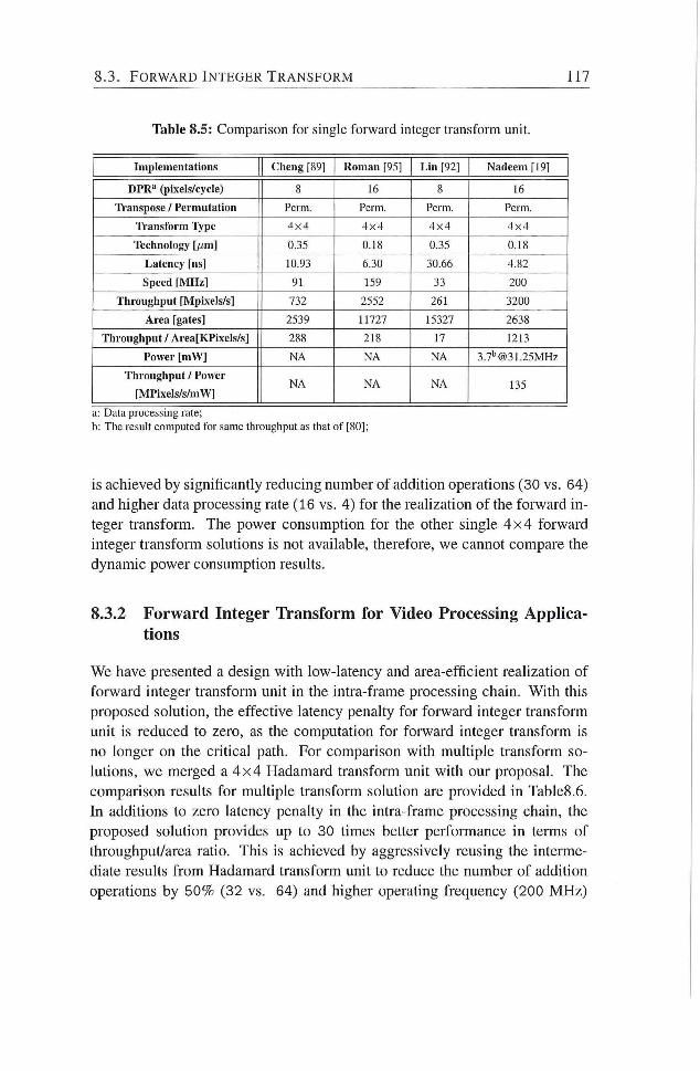
8.3. F O R W A R D I N T E G E R T R A N S F O R M 117
Table 8.5: Comparison for single forward integer transform unit.
Implementations Cheng [89] R o m a n [95] L i n [92] Nadeem [19]
D P R " (pixels/cycle) 8 16 8 16
Transpose / Permutation Perm. Perm. Perm. Perm.
Trans form l^pe 4 x 4 4 x 4 4 x 4 4 x 4
Teclmology [/jm] 0.35 0.18 0.35 0.18
Latency [ns] 10.93 6.30 30.66 4.82
Speed [ M H z ] 91 159 33 200
Throughput [Mpixels/s] 732 2552 261 3200
A r e a [gates] 2539 11727 15327 2638
Throughput / Area[KPixe l s / s ] 288 218 17 1213
Power [ m W ] N A N A N A 3.7''@31.25MHz
Throughput / Power
[MPixels / s /mW] N A N A N A 135
a: Data processing rate;
b: The result computed for same throughput as that of [80];
is achieved by significantly reducing number of addition operations (30 vs. 64)
and higher data processing rate (16 vs. 4) for the realization of the forward in
teger transform. The power consumption for the other single 4 x 4 forward
integer transform solutions is not available, therefore, we cannot compare the
dynamic power consumption results.
8.3.2 Forward Integer Transform for Video Processing Applications
We have presented a design with low-latency and area-efficient realizadon of
forward integer transform unit in the intra-frame processing chain. With this
proposed solution, the effective latency penalty for forward integer transform
unit is reduced to zero, as the computation for forward integer transform is
no longer on the critical path. For comparison with multiple transform so
lutions, we merged a 4 x 4 Hadamard transform unit wi th our proposal. The
comparison results for muldple transform soludon are provided in Table8.6.
In additions to zero latency penalty in the intra-frame processing chain, the
proposed solution provides up to 30 times better performance in terms of
throughput/area ratio. This is achieved by aggressively reusing the interme
diate results f rom Hadamard transform unit to reduce the number of addition
operations by 50% (32 vs. 64) and higher operating frequency (200 MHz)
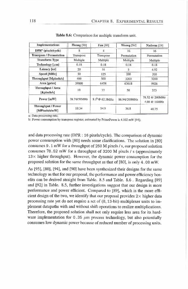
118 C H A P T E R S . E X P E R I M E N T A L R E S U L T S
Table 8.6: Comparison for multiple transform unit.
Implementations H u a n g [90] F a n [80] Woong [94] Nadeem [19]
D P R " (pixels/cycle) 8 4 16 16
Transpose / Permutation Transpose Transpose Permutation Permutation
Trans form Type Multiple Multiple Multiple Multiple
Teclmology [/jm] 0.18 0.18 0.18 0.18
Latency [ns] 20 16 5 4.92
Speed [ M H z ] 50 125 200 200
Throughput [Mpixels/s] 400 500 3200 3200
A r e a [gates] 39800 6458 63618 9926
Throughput / A r e a
[Kpixels/s] 10 77 50 323
Power [ m W ] 38.7@50MHz 9. l ' '@ 62.5MHz 86.9@200MHz 78.52 @ 200MHz
4.08 @ 16MHz
Throughput / Power
[MPixels / s /mW] 10.34 54.9 36.8 40.75
a: Data processing rate;
b: Power consumption by transpose register, estimated by PrimePower is 4.102 m W [94];
and data processing rate (DPR : 16 pixels/cycle). The comparison of dynamic
power consumption with [80] needs some clarifications. The solution in [80]
consumes 9 . 1 mW for a throughput of 250 M pixels / s, our proposed solution
consumes 78.52 m W for a throughput of 3200 M pixels / s (approximately
13 X higher throughput). However, the dynamic power consumption for the
proposed solution for the same throughput as that of [80], is only 4 . 08 mW.
As [95], [80], [94], and [90] have been synthesized their designs for the same
technology as that for our proposal, the performance and power efficiency ben
efits can be derived straight f rom Table. 8.5 and Table. 8.6 . Regarding [89]
and [92] in Table. 8.5, further investigations suggest that our design is more
performance and power efficient. Compared to [89], which is the more eff i
cient design of the two, we identify that our proposal provides 2 x higher data
processing rate yet do not require a set of (8,13-bit) multiplexer units to i m
plement datapaths with and without shift operations to realize multiplications.
Therefore, the proposed solution shall not only require less area for its hard
ware implementation for 0.35 /xm process technology, but also potentially
consumes low dynamic power because of reduced number of processing units.
8.4. I N V E R S E I N T E G E R T R A N S F O R M 119
8.4 Inverse Integer Transform
In Chapter 6, we have presented 2 hardware designs for inverse integer trans
form in H.264/AVC. The first design is intended for intra-frame encoder with
significandy reduced latency. The proposed design processes input data on-
the-fly in order to compute inverse integer transformed data block. From video
processing apphcadon perspecdve, the second proposed hardware design for
inverse integer transform, targets targets high-throughput and significantly less
dynamic power consumption for its implementadon. Experimental evaluation
of proposed designs is provided as follows:
8.4.1 Low-latency Inverse Integer Transform Design Evaluation
The proposed low-latency inverse integer transform design is described in
V H D L and synthesized by Synopsys Design Compiler (v2002, rev. 05) for
a maximum operadng frequency of 375 M H z with 0.18 / im CMOS standard
cell technology (v l .5) . The implementation is verified by comparing the simu
ladon results for various video test sequences with those of reference software
implementation [99].
The comparison of proposed hardware design for inverse integer transform unit
with other state-of-the-art designs in hterature is provided in Table 8.7. The
proposed design requires significantly less area (7512 gates) in terms of equiv
alent gate count for its hardware implementation. The proposed design with
a maximum operating frequency of 375 MHz, therefore, can easily meet the
throughput requirement of the real-dme processing of H D T V (1920x1080;
16 : 9; 30 frame per second) with an operadng frequency as low as 94 MHz .
It should be noted that all other designs in Table 8.7require one or more ad
ditional buffers to interface with the inverse quantization processing unit in
the intra-frame processing chain. Therefore, they require additional chip-area
for interface, whereas our proposed design does not require such buffers be
cause of the fact that it processes the input data-items on-the-fly and therefore,
requires only a single 16-bit register (it is included in 7512 gates).
The latency penalty of the proposed design is 2 .67 ns. The latency penalty
for our design can not be compared direcdy with those of [89], [92], and [93],
because of different process technology. The scale factors for a set of different
latest process technologies are provided in [100]. However, i t does not provide
a scale factor for 0 .18 /xm and 0.35 pm technologies. Since a scale factor of
2 .2 exist among technologies like (80nm and 40nm), and (70nm and 36nm).
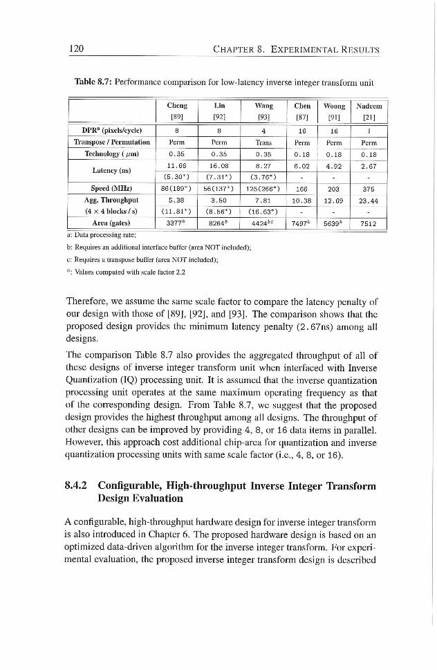
120 C H A P T E R S . E X P E R I M E N T A L R E S U L T S
Table 8.7: Performance comparison for low-latency inverse integer transform unit
C h e n g L i n W a n g C h e n Woong Nadeem
[89] [92] [93] 187] [91] [21]
D P R " (pixels/cycle) 8 8 4 16 16 1
Transpose / Permutation Perm Perm Trans Perm Perm Perm
Technology (lum) 0 . 3 5 0 . 3 5 0 . 3 5 0 . 1 8 0 . 1 8 0 . 1 8
Latency (ns) 1 1 . 6 6 1 6 . 0 8 8 . 2 7 6 . 0 2 4 . 9 2 2 . 6 7
Latency (ns) ( 5 . 3 0 * ) ( 7 . 3 1 * ) ( 3 . 7 6 * ) - - -
Speed ( M H z ) 8 6 ( 1 8 9 * ) 5 6 ( 1 3 7 * ) 1 2 5 ( 2 6 6 * ) 166 203 375
Agg. Throughput 5 . 3 8 3 . 5 0 7 .81 1 0 . 3 8 1 2 . 6 9 2 3 . 4 4
( 4 X 4 blocks / s) ( 1 1 . 8 1 * ) ( 8 . 5 6 * ) ( 1 6 . 6 3 * ) - - -
A r e a (gates) 3377'' 8264'" 4424^'= 7497'' 7512
a: Data processing rate;
b: Requires an additional interface buffer (area N O T included);
c: Requires a transpose buffer (area N O T included);
*: Values computed with scale factor 2.2
Therefore, we assume the same scale factor to compare the latency penalty of
our design with those of [89], [92], and [93]. The comparison shows that the
proposed design provides the minimum latency penalty (2.67ns) among all
designs.
The comparison Table 8.7 also provides the aggregated throughput of all of
these designs of inverse integer transform unit when interfaced with Inverse
Quantization (IQ) processing unit. I t is assumed that the inverse quantization
processing unit operates at the same maximum operating frequency as that
of the coiTesponding design. From Table 8.7, we suggest that the proposed
design provides the highest throughput among ah designs. The throughput of
other designs can be improved by providing 4, 8, or 16 data items in parallel.
However, this approach cost additional chip-area for quantization and inverse
quantization processing units with same scale factor (i.e., 4, 8, or 16).
8.4.2 Configurable, High-throughput Inverse Integer Transform Design Evaluation
A configurable, high-throughput hardware design for inverse integer transform
is also introduced in Chapter 6. The proposed hardware design is based on an
optimized data-driven algorithm for the inverse integer transform. For experi
mental evaluation, the proposed inverse integer transform design is described
8.5. A P P L I C A T I O N S P E C I F I C C U S T O M O P E R A T I O N S 121
in V H D L and synthesized by Synopsys Design Compiler (v2002, rev. 05) for
a maximum operating frequency of 166 M H z with 0.18 /xm CMOS standard
cell technology (vl .5) . The implementation is verified by comparing the simu
lation results for various video test sequences with those of reference software
implementation [99].
Since the dynamic power consumption for the inverse integer transform unit
using video test sequence data is not provided in the literature, we implemented
a parahel 2-D inverse integer transform based on architecture proposed in [95]
as a reference for the same technology and the maximum operating frequency.
The area-cost of proposed design, in terms of equivalent gate count, is 9.6 K
gates. The dynamic power consumption estimated for a number of video test
sequences with fine (Qp = 16) and coarse (Qp = 32) quantization parameter is
illustrated in Figure 8.5(a) and Figure 8.5(b) respectively.
The test results suggest that dynamic power consumption is greatly affected by
the Qp value chosen and a significant reducdon (up to 80%) can be achieved
by using a data-driven computation algorithm for the inverse integer trans
form. The number of operations to compute the inverse integer transform is
variable and depends on the input block type in contrast to the conventional
inverse integer transform algorithm with constant number of operations for all
types of input blocks. This result in a sigmficantiy reduced signal activity in
the hardware circuit and, therefore, lower dynamic power consumption. The
area-overhead for such an algorithm was reduced by designing a configurable
processing unit to share the hardware resources.
8.5 Application Specific Custom Operations
In Chapter 7, custom operations for 3 compute-intensive processing units in
H.264/AVC, are proposed for reconfigurable, soft-core, V L I W processor (p-
V E X ) . The Customized Functional Unit (CFU) implements these new apph
cation specific custom operations with latency of 2 cycles each as depicted
in Figure 7.1. The proposed custom operations for deblocking filter, intra-
prediction and transform units are based on the optimized algorithms already
provided in respective previous chapters in this dissertation. In this section,
we evaluate the performance gain and also compute related hardware resource
overhead for these custom operations reconfigurable, soft-core, V L I W proces
sor (p-YEX).
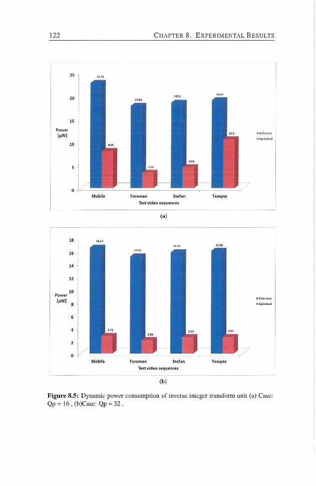
122 C H A P T E R 8. E X P E R I M E N T A L R E S U L T S
Figure 8.5: Dynamic power consumption of inverse integer transform unit (a) Case: Qp=16,(b)Case: Qp = 32 .
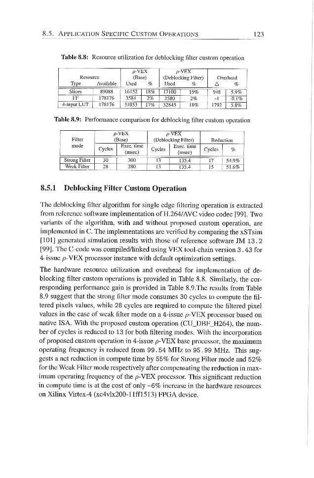
8.5. A P P L I C A T I O N S P E C I F I C C U S T O M O P E R A T I O N S 123
Table 8.8: Resource utilization for deblocking filter custom operation
p - V E X P- V E X
Resource (Base) (Deblocking Filter) Overhead Type Available Used % Used % A %
Slices 89088 16152 18% 17100 19% 948 5.9% F F 178176 3584 2% 3580 2% -4 -0.1 %
4-input L U T 178176 31053 17% 32845 18% 1792 5.8%
Table 8.9: Performance comparison for deblocking filter custom operation
P - V E X P - V E X Filter (Base) (Deblocking Filter) Reduction mode
Cycles Exec , time
(msec) Cycles
Exec , time
(msec) Cycles %
Strong Filter 30 300 13 135.4 17 54.9% Weak Filter 28 280 13 135.4 15 51.6%
8.5.1 Deblocking Filter Custom Operation
The (ieblocking filter algoiithm for single edge filtering operation is extracted
f rom reference software implementation of H.264/AVC video codec [99]. Two
variants of the algorithm, with and without proposed custom operation, are
implemented in C. The implementadons are verified by comparing the xSTsim
[101] generated simulation results with those of reference software JM 13. 2
[99]. The C-code was compiled/linked using V E X tool-chain version 3.43 for
4-issue /9-VEX processor instance with default opdmizadon setdngs.
The hardware resource utilization and overhead for implementadon of de
blocking filter custom operadons is provided in Table 8.8. Similarly, the cor
responding performance gain is provided in Table 8.9.The resuhs f rom Table
8.9 suggest that the strong filter mode consumes 30 cycles to compute the fib
tered pixels values, while 28 cycles are required to compute the filtered pixel
values in the case of weak fiker mode on a 4-issue /9-VEX processor based on
nadve ISA. With the proposed custom operadon (CU_DBF_H264), the num
ber of cycles is reduced to 13 for both filtering modes. With the incorporadon
of proposed custom operadon in 4-issue /9-VEX base processor, the maximum
operating frequency is reduced f rom 99.54 M H z to 95. 99 MHz. This sug
gests a net reduction in compute dme by 55% for Strong Eilter mode and 52%
for the Weak Filter mode respectively after compensating the reduction in max
imum operating frequency of the p - V E X processor. This significant reducdon
in compute time is at the cost of only - 6 % increase in the hardware resources
on X i l i n x Virtex-4 (xc4vlx200-llflF15I3) FPGA device.
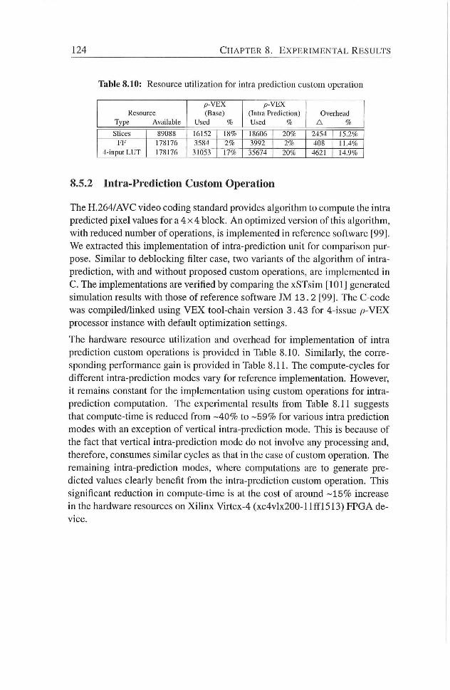
124 C H A P T E R S . E X P E R I M E N T A L R E S U L T S
Table 8.10: Resource utilization for intra prediction custom operation
Resource
Type Available
p - V E X
(Base)
Used %
p - V E X
(Intra Prediction)
Used %
Overhead
A %
Slices 89088 16152 18% 18606 20% 2454 15.2%
F F 178176 3584 2% 3992 2% 408 11.4%
4-input LUT 178176 31053 17% 35674 20% 4621 14.9%
8.5.2 Intra-Prediction Custom Operation
The H.264/AVC video coding standard provides algorithm to compute the intra
predicted pixel values for a 4 x 4 block. A n optimized version of this algorithm,
with reduced number of operadons, is implemented in reference software [99].
We extracted this implementation of intra-prediction unit for comparison pur
pose. Similar to deblocking filter case, two variants of the algorithm of intra-
predicdon, wi th and without proposed custom operadons, are implemented in
C. The implementadons are verified by comparing the xSTsim [101] generated
simuladon results with those of reference software JM 13.2 [99]. The C-code
was compiled/linked using V E X tool-chain version 3.43 for 4-issue p - V E X
processor instance with default opdmization setdngs.
The hardware resource utihzation and overhead for implementadon of intra
prediction custom operadons is provided in Table 8.10. Similarly, the corre
sponding performance gain is provided in Table 8.11. The compute-cycles for
different intra-prediction modes vary for reference implementation. However,
i t remains constant for the implementation using custom operadons for intra-
predicdon computadon. The experimental results f rom Table 8.11 suggests
that compute-time is reduced f rom -40% to -59% for various intra predicdon
modes with an exception of vertical intra-prediction mode. This is because of
the fact that vertical intra-prediction mode do not involve any processing and,
therefore, consumes similar cycles as that in the case of custom operation. The
remaining intra-prediction modes, where computations are to generate pre
dicted values clearly benefit f rom the intra-prediction custom operation. This
significant reduction in compute-time is at the cost of around - 1 5 % increase
in the hardware resources on Xihnx Virtex-4 (xc4vlx200-l l f f l 5 1 3 ) FPGA de
vice.
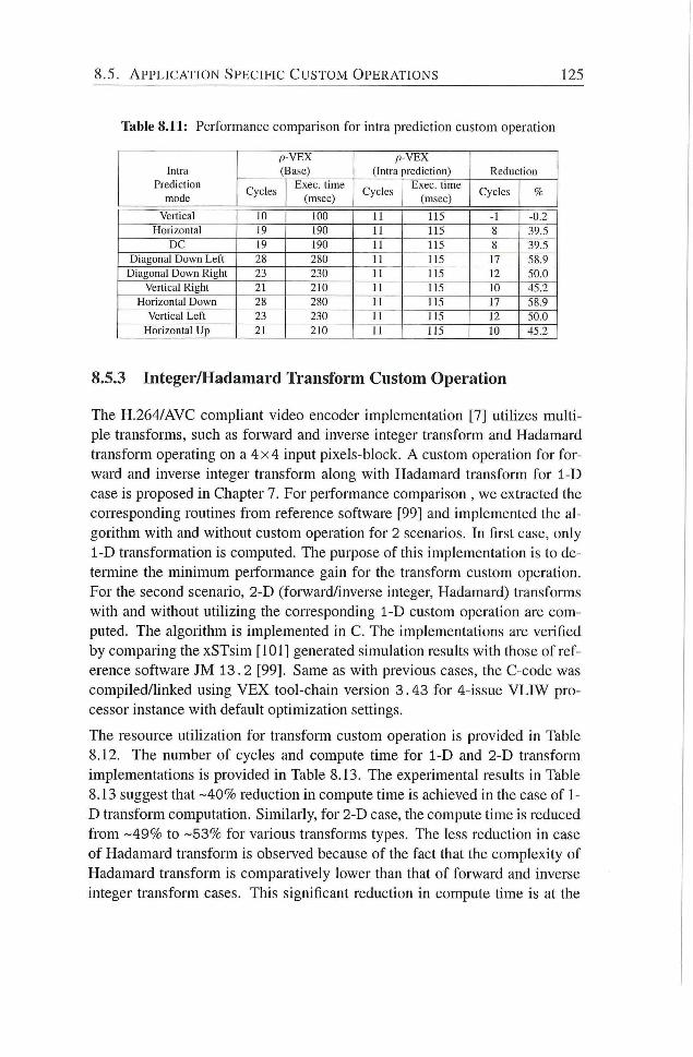
8 . 5 . A P P L I C A T I O N S P E C I F I C C U S T O M O P E R A T I O N S 125
Table 8.11: Performance comparison for intra prediction custom operation
P - V E X P - V E X
Intra (Base) (Intra prediction) Reduction
Prediction Cycles
Exec , time Cycles
Exec, time Cycles %
mode Cycles
(msec) Cycles
(msec) Cycles %
Vertical 10 too 11 115 -1 -0.2
Horizontal 19 190 11 115 8 39.5
D C 19 190 11 115 8 39.5
Diagonal Down Left 28 280 11 115 17 58.9
Diagonal Down Right 23 230 11 115 12 50.0
Vertical Right 21 210 11 115 10 45.2
Horizontal Down 28 280 11 115 17 58.9
Vertical Left 23 230 11 115 12 50.0
Horizontal Up 21 210 11 115 to 45.2
8.5.3 Integer/Hadamard Transform Custom Operation
The H.264/AVC comphant video encoder implementation [7] utihzes muld
ple transforms, such as forward and inverse integer transform and Hadamard
transform operating on a 4 x 4 input pixels-block. A custom operation for for
ward and inverse integer transform along with Hadamard transform for 1-D
case is proposed in Chapter 7. For peiformance comparison , we extracted the
corresponding routines f rom reference software [99] and implemented the al
gorithm with and without custom operation for 2 scenarios. In first case, only
1-D transformation is computed. The puipose of this implementadon is to de
termine the minimum performance gain for the transform custom operation.
For the second scenario, 2-D (forward/inverse integer, Hadamard) transforms
with and without udlizing the con-esponding 1-D custom operation are com
puted. The algorithm is implemented in C. The implementations are verified
by comparing the xSTsim [101] generated simuladon results with those of ref
erence software JM 13.2 [99]. Same as with previous cases, the C-code was
compiled/linked using V E X tool-chain version 3.43 for 4-issue V L I W pro
cessor instance with default opdmization settings.
The resource utilizadon for transform custom operadon is provided in Table
8.12. The number of cycles and compute time for 1-D and 2-D transform
implementadons is provided in Table 8.13. The experimental results in Table
8.13 suggest that -40% reduction in compute dme is achieved in the case of 1-
D transform computation. Similarly, for 2-D case, the compute time is reduced
f r o m - 4 9 % to -53% for various transforms types. The less reduction in case
of Hadamard transform is observed because of the fact that the complexity of
Hadamard transform is comparatively lower than that of forward and inverse
integer transform cases. This significant reducdon in compute dme is at the
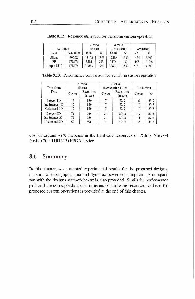
126 C H A P T E R S . E X P E R I M E N T A L R E S U L T S
Table 8.12: Resource utilization for transform custom operation
Resource
Type Available
p - V E X
(Base)
Used %
p - V E X
(Transform)
Used %
Overhead
A %
Slices 89088 16152 18% 17586 19% 1434 8.9%
F F 178176 3584 2% 3476 1% -108 -3.0%
4-input L U T 178176 31053 17% 33834 18% 2781 9.0%
Table 8.13: Performance comparison for transform custom operation
Transform
Type
p - V E X
(Base)
p - V E X
(Deblocking Filter) Reduction Transform
Type Cycles
Exec , time
(msec) Cycles
Exec , time
(msec) Cycles %
Integer-ID 13 130 7 72.9 6 43.9
Inv Integer-ID 12 120 7 72.9 5 39.3
Hadamard-ID 12 120 7 72.9 5 39.3
Integer-2D 76 760 34 354.2 42 53.4
Inv Integer-2D 75 750 34 354.2 41 52.8
Hadamard-2D 69 690 34 354.2 35 48.7
cost of around - 9 % increase in the hardware resources on Xihnx Virtex-4
(xc4vlx200-l l f f l 5 1 3 ) EPGA device.
8.6 Summary
In this chapter, we presented experimental results for the proposed designs,
in terms of throughput, area and dynamic power consumption. A compari
son with the designs state-of-the-art is also provided. Similarly, performance
gain and the corresponding cost in terms of hardware resource-overhead for
proposed custom operations is provided at the end of this chapter
9 Conclusions and Future Directions
INHIS this dissertation, we have presented several designs for compute-
intensive processing functions in fI .264/AVC. The proposed hardware de
signs are based on optimized algorithms with significantly less number of op
erations, when compared with those for original algorithms proposed in the
H.264/AVC video codec standard . Similarly, custom operations for the same
compute-intensive funcdons are also proposed in this dissertadon. These cus
tom operations are implemented in the datapath of reconfigurable, extensi
ble, soft-core V L I W processor (p-VEX). The performance gain and hardware
resource-overhead for these custom operations is determined experimentally
and presented in this dissertation.
In this chapter, we present concluding remarks along with major achievements
and possible future directions for this research work. The chapter is organized
as foUows: Section 9.1 provides summary of main conclusions of this dis
sertadon. Main contribudons of this dissertation are hsted in Secdon 9.2. In
Secdon 9.3, the problem statements addressed in this dissertation are revisited.
Einally, Section 9.4 outline some open issues and future direcdons based on
this research work.
9.1 Summary and Contributions
In Chapter 1, the importance of digital video coding, typical hardware plat
forms for video processing along with their merits and shortcomings are pre
sented. The challenges, problem statements and methodology to achieve high-
performance video processing systems are also presented in the same chapter
A motivation for a high-throughput, area-efficient and low-power solutions is
described. We argued that even though processor speeds and network band-
widths continue to increase, effective video coding/compression is essential to
127
128 C H A P T E R 9. C O N C L U S I O N S A N D F U T U R E D I R E C T I O N S
almost all of the muhimedia consumer apphcations and markets.
In Chapter 2, we have presented an overview of the latest and state-of-the-
art video coding standard H.264/AVC. Several different functional blocks of
the video codec are briefly described. The compute-intensive functional units
within the scope of video coding standard are identified. The state-of-the-art
high performance designs for these compute-intensive functional units, already
presented in the literature, are introduced briefly as part of related work. The
shortcomings of these hardware designs are also highlighted. Subsequently,
p-VEX reconfigurable, extensible, soft-core V L I W processor as a target hard
ware platform is introduced. The background knowledge for the processor's
architecture and design is also explained at the end of this chapter in reladon
with our subsequent proposal for custom operations for video processing.
In Chapter 3, we a low-power hardware design for deblocking filter core in
H.264/AVC is presented. As part of opdmization of deblocking fiker algo
rithm, a novel decomposidon of the deblocking filter kernels to reduce the
number of operadons by more than 5 1 % is proposed. Furthermore, we iden
tified mumally exclusive independent processing units within the optimized
algorithm and proposed to implement them separately with clock gating. .
Subsequently, for real-dme video processing apphcadons, we have presented
a high-throughput, area-efficient, hardware accelerator for the deblocking filter
in H.264/AVC. The optimizadon techniques employed and proposed hardware
design provides significantly higher throughput and reduced the on-chip area.
The proposed design easily provide reakdme filtering operadon for the H D T V
video format (4096x2304, 16:9) at 30 fps and meet the throughput require
ments of all levels (level 1-5.1) in H.264/AVC video coding standard.
Similarly, in Chapter 4, a high-performance hardware design for intra-
prediction in H.264/AVC is presented. Again, in order to reduce the complex
ity of the intra-prediction algorithm, optimizations are carried out to lower the
number of operadons. The opdmization of algorithm for 4 x 4 intra-predicdon
modes enabled us to reduce the number of addition by 60% when compared
with that of standard predicdon equadons. Similarly, overlapped data-paths
for the 4 x 4 ,8x8 , and 16x16 block types also helped to greatly reduce the re
quired on-chip resources for its hardware implementation. With an operating
frequency of 150 MHz , the proposed intra-predicdon unit can easily meet the
real-time processing requirement of H D T V video frame formats.
In Chapter 5, we proposed two soludons for reahzadon of the forward in
teger transform in the processing chain of intra-only frame encoder apphca
tions. The first solution targeted image compression applicadons running on
9.2. M A I N C O N T R I B U T I O N S 129
battery-powered electronic devices, such as Digital Stih Camera (DSC). The
proposed solution utilized a novel 2-D transform to derive the forward integer
transform coefficients directly f rom that of Hadamard transfonn with signifi
cantly reduced number of operations and, therefore, area and power consump
tion. The second solution targeted video compression apphcations process
ing high-resolution video frames in real-time, such as Digital Video Camera
(DVC), Television Studio Broadcast and Surveillance video. The proposed
solution reduced the effective latency penalty of the forward integer trans
form to zero. Moreover, i t aggressively re-used the intermediate results f rom
Hadamard transform and, therefore, requires significantly reduced number of
operations and thus less area for its hardware implementation.
In Chapter 6, we proposed two hardware designs for the inverse integer trans
form in H.264/AVC video codec. The first design is intended for intra-frame
encoder with reduced latency. The proposed design process the input data
on-the-fly to produce the inverse transformed data block. A data-driven al
gorithm with variable number of operations is also introduced in this chapter
The second hardware design, based on the data-driven algorithm, enabled us
to provide high-throughput and consume significantly less dynamic power for
its implementation.
In Chapter 7, we proposed to incorporate a customized functional unit in the
datapath of reconfigurable, soft-core, V L I W processor. This customized func
tional unit implements apphcation specific custom operadons for the compute
intensive processing functions in video codec H.264/AVC. More specifically,
one custom instruction for deblocking filter, two custom operadonss to com
pute the complete predicted 4 x 4 pixel block in intra-predicdon module and
another three custom operationss for forward/inverse integer transform along
with Hadamard transform are proposed in this chapter. It is proposed to use
the optimized algorithms with significantly reduced number of operation for
the implementadon of these custom operadons in CFU.
In Chapters, we have presented experimental resuhs for the proposed design
in previous chapters of this dissertation. A comparison with state-of-the-art is
also presented in the same chapter.
9.2 Main Contributions
The research carried out in the course of this PhD project is published in several
sciendfic publicadons. This secdon highhghts the main contributions of the
research work described in this dissertation and are provided as follows:
130 C H A P T E R 9. C O N C L U S I O N S A N D F U T U R E D I R E C T I O N S
1. In-loop deblocking filter.
• The complexity of in-loop deblocking filter algorithm is reduced
by novel decomposition of filter kernels and intra-module opti
mizations. The complexity of the deblocking filter algorithm is
reduced by more than 51% when compared with that of algorithm
described in the video coding standard H.264/AVC [Section: 3.2],
[16].
• A low-power hardware design for deblocking filter unit is proposed
in this dissertation. The proposed design consumes 43 m W dy
namic power on a Xi l inx Virtex I I FPGA and consumes 16.36 / iW,
when synthesized using 0 .18 /xm CMOS standard cell hbrary. The
FPGA implementation on Virtex I I can work at 76 MHz, whereas
the maximum operating frequency for 0.18 fim process technol
ogy is 200 MHz. Experimental results suggest that the dynamic
power consumption is reduced up to 50%, when compared with
state-of-the-art designs in literature. [Table:8.2] [17].
• For real-time video processing apphcations, a high-throughput,
area-efficient hardware design, based on the low-power filter unit,
is proposed. . This design utihzes 2 filter units and, therefore,
can process input pixels on-the-fly in both horizontal and verti
cal directions. The proposed design provides significantly higher
throughput (more than 63% when compared with state-of-the-art
in literature having similar area-cost) and require less on-chip area
(around 35% when compared with state-of-the-art in literature hav
ing similar throughput) [Table: 8.3] [16].
2. Intra-prediction
• The complexity of intra-prediction algorithm for various intra-
prediction modes is reduced by 27% - 60% in comparison with intra-
prediction algorithm proposed in H.264/AVC video coding stan
dard. A configurable, high-throughput, and area-efficient hardware
design for intra-prediction unit, based on the reduced complexity
intra-prediction algorithm, is proposed in this dissertadon. The
comparison with other state-of-the-art suggests that our proposed
hardware design provides 50%-75% performance improvement and
requires only 2 I K gates for its implementation, when synthesized
under 0.18 / im CMOS standard ceh technology [18].
9.2. M A I N C O N T R I B U T I O N S 131
3. Forward integer transform
• A transformation, to compute integer-transformed residual block
f rom Hadamard-transformed residual block in the processing chain
of H.264/AVC video codec, is proposed in this dissertation. This
approach reduces the number of addition operations by more than
507. for reahzation of integer transform in the video codec. The
comparison with the existing single 4 x 4 forward integer transform
solutions f rom the literature suggest that the proposed solution pro
vides the minimum latency penalty (4.82ns) among all solutions
and also requires significantly less area (2 . 6K gates) i n terms of
equivalent gate count for its hardware implementation. Therefore,
it provides up to 5 times better performance in terms of through
put/area ratio for the same process technology. [19].
• Similarly, a low-latency and area-efficient solution for realization
of forward integer transform unit in the intra-frame processing
chain is proposed. With this proposed solution, the effective la
tency penalty for the forward integer transform unit is reduced to
zero. In additions to zero latency penalty in the intra-frame pro
cessing chain, the proposed solution provides up to 30 times better
performance in terms of throughput/area ratio. [19].
4. Inverse integer transform
• For inverse integer transform unit, a configurable, low-power hard
ware design is presented in this dissertation. The proposed design
is based on a data-driven computation algorithm for the inverse in
teger transform. It efficiently exploits the zero-valued coefficients
in the input blocks to reduce dynamic power consumption. The ex
perimental results show that the proposed design consumes signif
icantly less dynamic power (up to 807, reduction), when compared
with existing conventional designs for the inverse integer trans
form, with a small area-overhead (approximately 2 K gates) [20]
[21].
5. Custom instructions/processing units for extensible, reconfigurable,
soft-core V L I W processor (p -VEX) .
• In this dissertation, we also proposed custom operations for de
blocking filter, intra-prediction and forward/inverse integer trans
fo rm units in H.264/AVC foe a reconfigurable V L f W processor
132 C H A P T E R 9. C O N C L U S I O N S A N D F U T U R E D I R E C T I O N S
The datapath is based on the optimized algorithms presented in
this dissertation. The proposed custom operations significantly re
duce the compute time (approximately 407. - 59°/. ) for the corre
sponding compute-intensive functions in H.264/AVC on a recon
figurable, soft-core V L I W processor (p -VEX) . [8.9, 8.11, 8.13].
9.3 Problem Statements Revisited
The answers to the research questions presented in Section 1.3 can, therefore,
be summarized as follows:
• How to achieve high-performance and flexible processing in video pro
cessing/compression applications? High-performance in terms of high-
throughput typically comes f rom parallelism in application kernels.
Similariy, beside high-performance in terms of throughput, the realiza
tion of advanced video coding on battery-powered multimedia electronic
devices with reduced on-chip area and lower dynamic power, is also
extremely important. Although parallel processing or high-throughput,
typically in a module for filtering process of video data, can be achieved
by duphcating the circuit. However, it doesn't help in other dimensions
of constraint based design-space of that module. In this dissertation, we
have demonstrated that an optimized algoiithm with reduced complex
ity is a key to achieve high-performance in terms of throughput, area
and dynamic power consumption at the same time [Chapters: 3, 4, 5,
6]. The flexibility to adapt to video coding standard evolutions and mar
ket/technology induced changes can be satisfied by utilizing reconfig
urable fabric. Reconfigurable processors provide the flexibility as wel l
as performance for the applications that are amenable to acceleration
with reconfigurable hardware. In this dissertation, we also proposed to
extend the ISA of extensible, reconfigurable, soft-core V L I W processor
(p -VEX) with application specific custom operations for various video
processing units in H.264/AVC video coding standard. This includes
deblocking filter, intra-prediction and forward/inverse integer transform
units as weh as Hadamard transform [7].
• How to reduce the coding complexity and improve the real-time per
formance without compromising the video cpiality? The video coding
algorithm defines a detailed implementation outline of a required orig
inal function and, therefore, determines how to solve the problem and
9.3. P R O B L E M S T A T E M E N T S R E V I S I T E D 133
how to reduce the original complexity. In order to do an optimal imple
mentation, it is essential to fu l ly understand the principles behind, and
algorithms employed, in video coding as it is a key to reduce power con
sumption and improve efficiency. In this dissertation, we demonstrated
that improved throughput and lower dynamic power consumption can
be achieved at the same time by reducing algorithm complexity, (please
refer to Section 9.2 for summary of our contributions and supporting
experimental results). The optimized algorithm with lower number of
operations not only require less on-chip area for its implementation, the
target throughput can be achieved at lower clock rate or i n less number
of cycles. The optimized algorithm with reduced number of operations
also helps to lower the dynamic power consumption of the processing
modules. The complexity of the algorithm can be reduced by intra-
module optimization to remove the redundancy in the algorithm itself
(e.g. deblocking filter and intra-prediction modules), or by inter-module
optimizations by reusing the previous results (e.g. forward integer trans
form). Similarly, the complexity can also be reduced by considering
the statisdcal nature of the input signal in the processing module (e.g.
inverse integer transform module). A n adaptive design to exploit the
stadsdcal redundancy in the video signal not only helps to carry out
required processing in reduced number of operations but also helps to
significantly lower the the dynamic power consumption.
• How can reconfigurable computing be utilized to improve the flexibil
ity and peiformance for video coding signal processing applications?
Customizadon of reconfigurable processors is a way forward to improve
the performance for a moderate cost. In this dissertation, we extended
the ISA of p -VEX reconfigurable soft-core V L I W processor with appli
cation specific custom operations such as adaptive in-loop deblocking
filter, intra-predicdon, forward integer transform, inverse integer trans
fo rm and Hadamard transform in H.264/AVC video codec. The cus
tomized modules implemented in the datapath of p - V E X processor, for
the proposed custom operadons, are based on the optimized algorithms
for these modules already discussed in the dissertation. Because of the
reduced number of operations and extensive parallel processing in the
proposed custom operations for video processing, it not only signifi
cantly reduces the required number of cycles at the cost of slight in
crease in hardware resources but can potentially reduce the dynamic
power consumption as well (please refer to Secdon 9.2 for summary
of our contributions and supporting experimental results).
134 C H A P T E R 9. C O N C L U S I O N S A N D F U T U R E D I R E C T I O N S
9.4 Future Directions
This section provides future research directions and improvements to the work
presented in this dissertation:
This dissertation focused on several compute-intensive processing functions
in FI.264/AVC video codec and proposed low-power, area-efficient and high-
throughput hardware designs. The algorithms for these compute-intensive
functions were optimized to reduce algorithm complexity in terms of num
ber of arithmetic operations for their implementation. Similar efforts can be
made for video pre-, and post-processing chain. Moreover, the proposed con
cepts can be further extended for the image processing algorithms and also for
the upcoming video coding standard H.265.
In this dissertadon, we targeted to reduce the power consumpdon at mod
ule/algorithm level. However, there is a need to deal with the power-related
issues at all abstracdon levels (process technology, module/processor design,
and application levels).
Custom operations for reconfigurable soft-core processor were proposed in this
dissertadon. These custom operations and datapaths were designed manually,
which is time consuming. This process need to be automated by designing
new tools similar to that used in ASIP. Similarly, low-power optimizadons,
intelligent algorithms and transformation techniques need to be investigated
for automated design of efficient datapaths.
In Chapter 3, we proposed a hardware design for deblocking filter based on
double filter units. Two edges (horizontal and vertical edges) are processed
simultaneously and, the proposed design can meet the throughput requirement
for H.264/AVC video codec up to level 5.1. For even higher throughput. The
proposed design can be extended by employing more filter units to process all
horizontal/vertical edges at 4 x 4 , 8 x 4 or 1 6 x 4 pixels block level to reduce
the number of filtering cycles per macroblock at the cost of additional on-chip
area.
In Chapter 4, a design for intra-prediction module is presented. In video codec,
the M B is either encoded in intra or inter-encoding mode. Both of these modes
are mutually exclusive. Moreover, the structure of intra-prediction filter ker
nels and SAD computation are similar Therefore, the same hardware re
sources can be efficiently utilized by reusing them for SAD computation in
case of inter encoding mode of a M B .
In this dissertation, we proposed hardware designs for different compute-

9.4. F U T U R E D I R E C T I O N S 135
intensive modules in H.264/AVC. We plan to design other modules such as
CAVLC/CABAC and integrate them all to implement complete video codec.

Bibliography
[1] J. Meehan, S. Busch, J. Noel, and F. Noraz. Multimedia IP Architecture
Trends in the Mobile Multimedia Consumer Device. Image Communi
cation., 25(5):317-324, June 2010.
[2] T. Wiegand, G.J. Sullivan, G. Bjontegaard, and A. Luthra. Overview of
the H.264/AVC Video Coding Standard. IEEE Transactions on Circuits
and Systems for Video Technology, 13(7):560-576, j u ly 2003.
[3] Yen-Kuang Chen and S. Y. Kung. Trend and Challenge on System-on-
a-Chip Designs. Journal of Signal Processing and System, 53(1-2):217-
229, November 2008.
[4] Yen-Kuang Chen, Eric Q. L i , Xiaosong Zhou, and Steven Ge. Im
plementation of H.264 Encoder and Decoder on Personal Computers.
Journal of Visual Communication and Image Representation, 17(2):509
- 532, 2006.
[5] S. Donggyu. High Efficiency Video Coding(HEVC). uri-
http://goo.gl/U29qll.
[6] Cisco Visual Networking Index: Global Mobile Data Traffic Forecast
Update,2012-2117. h t t p : / / g o o . g l / 0 4 Z 3 V W , 2013.
[7] Advanced Video Coding for Generic Audiovisual Services, 2005.
[8] J. Ostermann, J. Bormans, P. List, D. Marpe, M . Narroschke, F. Pereira,
T. Stockhammer, and T. Wedi. Video Coding with H.264/AVC:Ttools,
Performance, and Complexity. IEEE Magazine on Circuits and Systems,
4(1):7 - 28, quarter 2004.
[9] K. ; Salmimaa M . ; Hallapuro A.; Lainema J. Willner, K. ; Ugur. Mobile
3D Video Using M V C and N800 Internet Tablet. In 3DTV Conference:
The True Vision - Capture, Transmission and Display of 3D Video, pages
69-72, 2008.
[10] U.J. Kapasi, S. Rixner, W.J. Dally, B. Khailany, J.H. Ahn, P Matt-
son, and J.D. Owens. Programmable Stream Processors. Computer,
36(8):54-62, Aug. 2003.
[11] Shuai Hu, Zhe Zhang, Mengsu Zhang, and Tao Sheng. Optimization of
Memory Allocation for H.264 Video Decoder on Digital Signal Proces
sors. In Image and Signal Processing, 2008. CISP '08. Congress on,
volume 2, pages 71-75, May.
137
138 B I B L I O G R A P H Y
[12] G. R. Stewart. Implementing Video Compression Algorithms on Re
configurable Devices, June. 2009.
[13] K. Diefendorff and RK. Dubey. How multimedia workloads w i l l change
processor design. Computer.
[14] R Faraboschi, G. Brown, J. Fisher, G. Desoll, and F. Homewood. Lx:
A Technology Platform for Customizable V L I W Embedded Processing.
In International Symposium on Computer Architecture, pages 203-213,
lune.
[15] P. Faraboschi J. Fisher and C. Young. Embedded Computing: A V L I W
Approach to Architecture, Compilers and Tools., 2004.
[16] M . Nadeem, S. Wong, G. Kuzmanov, and A. Shabbir A High-
throughput, Area-efficient Hardware Accelerator for Adaptive Deblock
ing Filter in H.264/AVC. In lEEE/ACM/IFIP 7th Workshop on Embed
ded Systems for Real-Time Multimedia (ESTIMedia), pages 18-27, Oct.
2009.
[17] M . Nadeem, S. Wong, G. Kuzmanov, A . Shabbir, M.F. Nadeem,
and F. Anjam. Low-power, High-throughput Deblocking Filter for
H.264/AVC. In International Symposium on System on Chip (SoC),
pages 93-98, Sept. 2010.
[18] M . Nadeem, S. Wong, and G. Kuzmanov. A n Efficient Hardware Design
for Intra-prediction in H.264/AVC Decoder, year=2011, month=Apr,
pages=l-6,. In Saudi International Electronics, Comnumications and
Photonics Conference (SIECPC).
[19] M . Nadeem, S. Wong, and G. Kuzmanov. An Efficient Realization
of Forward Integer Transform in H.264/AVC Intra-frame Encoder. In
International Conference on Embedded Computer Systems (SAMOS),
pages 71-78, ju ly 2010.
[20] Muhammad Nadeem, Stephan Wong, and Georgi Kuzmanov. Con
figurable, Low-power Design for Inverse Integer Transfonn in
H.264/AVC. In International Conference on Frontiers of Information
Technology (IFIT), pages 32:1-32:5. A C M , 2010.
[21] M . Nadeem, S. Wong, and G. Kuzmanov. Inverse Integer Transform in
H.264/AVC Intra-frame Encoder. In IEEE International Symposium on
Electronic Design, Test and Application (DELTA), pages 228-233, Jan.
2011.
B I B L I O G R A P H Y 139
[22] H.S. Malvar, A . Hallapuro, M . Karczewicz, and L . Kerofsky. Low-
complexity Transform and Quantization in H.264/AVC. IEEE Transac
tions on Circuits and Systems for Video Technology, 13(7):598 - 603,
July 2003.
[23] D. Marpe, H . Schwarz, and T. Wiegand. Context-based Adaptive B i
nary Arithmetic Coding in the H.264/AVC Video Compression Stan
dard. IEEE Transactions on Circuits and Systems for Video Technology,
13(7):620-636, July.
[24] P. List, A . Joch, J. Lainema, G. Bjontegaard, and M . Karczewicz. Adap
tive deblocking filter. IEEE Transactions on Circuits and Systems for
Video Technology, 13(7):614-619, July 2003.
[25] P. Benzie, J. Watson, R Surman, I . Rakkolainen, K. Hopf, H . Urey,
V. Sainov, and C. von Kopylow. A Survey of 3DTV Displays: Tech
niques and Technologies. IEEE Transactions on Circuits and Systems
for Video Technology, 17(11): 1647 -1658, nov. 2007.
[26] Bin Sheng, Wen Gao, and D i Wu. An Implemented Architecture of De
blocking Filter for H.264/AVC. In International Conference on Image
Processing (ICIP), volume 1, pages 665-668, Oct 2004.
[27] Chung-Ming Chen and Chung-Ho Chen. A Memory Efficient Architec
ture for Deblocking Filter in H.264 Using Vertical Processing Order. In
International Conference on Intelligent Sensors, Sensor Networks and
Information Processing, pages 361-366, Dec. 2005.
[28] Chung-Ming Chen and Chung-Ho Chen. Configurable V L S I Architec
ture for Deblocking Filter in H.264/AVC. IEEE Transactions on Veiy
Large Scale Integration (VLSI) Systems, 16(8): 1072-1082, Aug. 2008.
[29] Qing Chen, Wei Zheng, Jian Fang, Kai Luo, Bing Shi, Ming Zhang,
and Xianmin Zhang. A Pipehned Hardware Architecture of Deblocking
Filter in H.264/AVC, booktitle = Intemational Conference on Commu
nications and Networking in China (ChinaCom), year - 2008, pages =
815—819, months Aug.,.
[30] C. M . Cheng and C. H . Chen. A Memory Efficient Architecture for
Deblocking Filter in H.264 Using Vertical Processing Order In IEEE
International Conference on InteUigent Sensors, Sensor Networks. In
formation Process, pages 361-366, 2005.
140 B I B L I O G R A P H Y
[31] Chao-Chung Cheng and Tian-Sheuan Chang. A n Hardware Efficient
Deblocking Filter for H.264/AVC. In International Conference on Con
sumer Electronics, ICCE. 2005 Digest of Technical Papers, pages 235¬
236,Jan. 2005.
[32] Chao-Chung Cheng, Tian-Sheuan Chang, and Kun-Bin Lee. A n In-
place Architecture for the Deblocking Filter in H.264/AVC, journal -
IEEE Transactions on Circuits and Systems I I : Express Briefs,, year =
2006, volume = 53, pages - 530-534, number = 7, month - July, issn
= 1549-7747.
[33] Heng-Yao L i n , Jwu-Jin Yang, Bin-Da L iu , and Jar-Ferr Yang. Efficient
Deblocking Filter ArchitecUire for H.264 Video Coders. In IEEE Inter
national Symposium on Circuits and Systems (ISCAS), page 4 pp. May
2006.
[34] G. Khurana, A . A . Kassim, Tien Ping Chua, and M . B . M i . A Pipelined
Hardware Implementation of In-loop Deblocking Filter in H.264/AVC.
IEEE Transactions on Consumer Electronics, 52(2):536-540, May
2006.
[35] Sung Deuk K i m , Jaeyoun Y i , Hyun Mun K i m , and Jong Beom Ra.
A Deblocking Filter With Two Separate Modes in Block-based Video
Coding. IEEE Transactions on Circuits and Systems for Video Teclmol
ogy, 9(1): 156-60, Feb 1999.
[36] Byung-Joo K i m , Jae-Il Koo, Min-Cheol Hong, and Seongsoo Lee. Low-
Power H.264 Deblocking Fiher Algorithm and hs SoC Implementadon.
In Long-Wen Chang and Wen-Nung Lie, editors. Advances in Image
and Video Technology, volume 4319 of Lecture Notes in Computer Sci
ence, pages 771-779. Springer Beriin / Heidelberg, 2006.
[37] Kyeong-Yuk M i n and Jong-Wha Chong. A Memory and Performance
Optimized Architecture of Deblocking Filter in H.264/AVC. In Interna
tional Conference on Multimedia and Ubiquitous Engineering (MUE),
pages 220-225, Apr i l 2007.
[38] S.Goto L . L i and and T. Ikenaga. A Highly ParaUel Architecture for
Deblocking Filter in H.264/AVC. lEICE Transactions on Information
and Systems, E88-D(7):1623 -1629, 2005.
[39] Lingfeng L i , Satoshi Goto, and Takeshi Ikenaga. A n Efficient De
blocking Filter Architecture with 2-dimensional Parallel Memory for
B I B L I O G R A P H Y 141
H.264/AVC. In Proceedings ofthe 2005 Asia and South Pacific Design
Automation Conference, pages 623-626. A C M , 2005.
[40] Tsu-Ming Liu , Wen-Ping Lee, Ting-An L in , and Chen-Yi Lee. A
Memoiy-efficient Deblocking Filter for H.264/AVC Video Coding. In
IEEE International Symposium on Circuits and Systems, ISCAS 2005,
volume 3, pages 2140-2143, May 2005.
[41] Tsu-Ming L iu , Wen-Ping Lee, and Chen-Yi Lee. An In/Post-Loop De
blocking Filter With Hybrid Filtering Schedule. IEEE Transactions on
Circuits and Systems for Video Technology, 17(7):937-943, July 2007.
[42] Miao Sima, Yuanhua Zhou, and Wei Zhang. A n Efficient Architecture
for Adaptive Deblocking Filter of H.264/AVC Video Coding. IEEE
Transactions on Consumer Electronics, 50(l):292-296, Feb 2004.
[43] NamThang Ta, JinSeon Youn, HuiGon K i m , JunRim Choi, and Seung-
Soo Han. Low-power High-throughput Deblocking Filter Architecture
for H.264/AVC. In International Conference on Electronic Computer
Technology, pages 627-631, Feb. 2009.
[44] M . Pariak and I . Hamzaoglu. A Low Power Implementadon of H.264
Adaptive Deblocking Filter Algorithm. In NASA/ESA Conference on
Adaptive Hardware and Systems, pages 127-133, Aug. 2007.
[45] M . Pariak and I . Hamzaoglu. Low power H.264 deblocking Filter Hard
ware Implementations. IEEE Transactions on Consumer Electronics,
54(2):808-816, May 2008.
[46] Shen-Yu Shih, Cheng-Ru Chang, and Youn-Long L in . A Near Opdmal
Deblocking Filter for H.264 Advanced Video Coding. In As/a and South
Pacific Conference on Design Automation, pages 170-175., jan. 2006.
[47] W.T. Staehler, E.A. Berriel, A . A . Susin, and S. Bampi. Architecture
of an H D T V Intraframe Predictor for a H.264 Decoder In Interna
tional Conference on Veiy Large Scale Integration (IFIP), pages 228¬
233, Oct. 2006.
[48] F. Tobajas, G.M. Callico, PA. Perez, V. de Armas, and R. Sarmiento.
A n Efficient Double-Filter Hardware Architecture for H.264/AVC De
blocking Filtering. IEEE Transactions on Consumer Electronics,
54(1): 131-139, Feb. 2008.
142 B I B L I O G R A P H Y
[49] J. Webb. Video deblocking filter, Feb 2003.
[50] Ke X u and Chiu-Sing Choy. A Five-Stage Pipeline, 204 Cycles/MB,
Single-Port SRAM-Based Deblocking Filter for H.264/AVC. IEEE
Transactions on Circuits and Systems for Video Technology, 18(3):363-
374, Mar 2008.
[51] Yu-Wen Huang, To-Wei Chen, Bing-Yu Hsieh, Tu-Chih Wang, Te-Hao
Chang, and Liang-Gee Chen. Architecture Design for Deblocking Filter
in H.264/JVT/AVC. In International Conference on Multimedia arid
Expo (ICME), volume 1, pages 1-693-6, lu ly 2003.
[52] G. Zheng and L . Yu. A n Efficient Architecture Design for Deblocking
Loop Filte. In Picture Coding Symposium, 2004.
[53] S. Krishnan V. Venkatraman and N . Ling. Architecture for De-blocking
Filter in H.264. In Picture Coding Symposium, 2004.
[54] K .K . Pang and T.K. Tan. Optimum Loop Filter in Hybrid Coders. IEEE
Transactions on Circuits and Systems for Video Technology, 4(2): 158¬
167, Apr 1994.
[55] Yung-Lyul Lee and HyunWook Park. Loop Filtering and
Post-filtering for Low-bit-rates Moving Picture Coding, jour
nal = Signal Processing: Image Communication, year ~
2001, volume = 16, pages = 871-890, number = 9, doi =
I0.1016/S0923-5965(00)00048-5, issn = 0923-5965, url =
http://www.sciencedirect.com/science/article/pii/S0923596500000485.
[56] Shih-Chien Chang, Wen-Hsiao Peng, Shih-Hao Wang, and Tihao Chi
ang. A Platform Based Bbus-interleaved Architecture for De-blocking
Filter in H.264/MPEG-4 AVC, joumal = IEEE Transactions on Con
sumer Electronics, year = 2005, volume = 51, pages = 249—255, num¬
ber = 1, month = Feb., doi = 10.1109/TCE.2005.1405728, issn = 0098¬
3063.
[57] Fangwen Fu, Xinggang L in , and Lidong Xu. Fast Intra Prediction Algo
rithm in H.264-AVC, year=2004, month=Aug, volume=2, pages=l 1 9 1 -
1194 volume = 2,. In International Conference on Signal Processing
(ICSP).
B I B L I O G R A P H Y 143
[58] Chao-Chung Cheng and Tian-Sheuan Chang. Fast Three Step Intra Pre
diction Algorithm for 4x4 Blocks in H.264. In IEEE Intemational Sym
posium on Circuits and Systems (ISCAS), volume 2, pages 1509-512,
May 2005.
[59] Chao-Hsuing Tseng, Hung-Ming Wang, and lar-Ferr Yang. Enhanced
Intra-4 x4 Mode Decision for H.264/AVC Coders. IEEE Transactions
on Circuits and Systems for Video Technology, 16(8): 1027-1032, Aug
2006.
[60] Jhing-Fa Wang, lia-Ching Wang, Jang-Ting Chen, An-Chao Tsai,
and A . Paul. A Novel Fast Algorithm for Intra Mode Decision in
H.264/AVC Encoders. In IEEE Intemational Symposium on Circuits
and Systems (ISCAS), page 4 pp.. May 2006.
[61] Jia-Ching Wang, Jhing-Fa Wang, Jar-Ferr Yang, and Jang-Ting Chen.
A Fast Mode Decision Algorithm and Its V L S I Design for H.264/AVC
Intra-Prediction. IEEE Transactions on Circuits and Systems for Video
Technology, 17(10):1414-1422, Oct 2007.
[62] Byeongdu La, Minyoung Eom, and Yoonsik Choe. Fast Mode Decision
for Intra Prediction in H.264/AVC Encoder. In IEEE International Con
ference on Image Processing (ICIP), volume 5, pages 321-324, Sept
2007.
[63] An-Chao Tsai, A . Paul, Jia-Ching Wang, and Jhing-Fa Wang. Intensity
Gradient Technique for Efhcient Intra-Prediction in H.264/AVC. IEEE
Transactions on Circuits and Systems for Video Teclmology, 18(5):694-
698, May 2008.
[64] Yan Ye and M . Karczewicz. Improved h.264 intra coding based on b i
directional intra predicdon, direcdonal transfonn, and adaptive coeffi
cient scanning. In IEEE Intemational Conference on Image Processing
(ICIP), pages 2116-2119, Oct 2008.
[65] X u n He, Dajiang Zhou, Jinjia Zhou, and S. Goto. A New Architecture
for High Performance Intra Prediction in H.264 Decoder In Interna
tional Symposium on InteUigent Signal Processing and Communication
Systems (ISPACS), pages 41-44, Jan. 2009.
[66] Yu-Wen Huang, Bing-Yu Hsieh, Tung-Chien Chen, and Liang-Gee
Chen. Analysis, Fast Algorithm, and V L S I Architecture Design for
144 B I B L I O G R A P H Y
H.264/AVC Intra Frame Coder. IEEE Transactions on Circuits and Sys
tems for Video Technology, 15(3):378 - 401, March 2005.
[67] Genhua Jin and Hyuk-Jae Lee. A Parallel and Pipelined Execution
of H.264/AVC Intra Prediction. In IEEE International Conference on
Computer and Information Technology (CIT), page 246, Sept. 2006.
[68] Chun-Wei Ku, Chao-Chung Cheng, Guo-Shiuan Yu, Min-Chi Tsai, and
Tian-Sheuan Chang. A High-Definition H.264/AVC Intra-Frame Codec
IP for Dighal Video and Sdh Camera Applications. IEEE Transactions
on Circuits and Systems for Video Technology, 16(8):917-928, Aug.
2006.
[69] D. Marpe, V. George, H . L . cycon, and K. U . Barthel. Performance
Evaluation of Motion-JPEG2000 in Comparison with H.264/AVC Op
erated in Pure Intra Coding Mode, volume 13, pages 129-137, 2003.
[70] E. Sahin and I . Hamzaoglu. A n Efficient Hardware Architecture for
H.264 Intra Prediction Algorithm. In Design, Automation Test in Europe
Conference Exhibition, 2007. DATE '07, pages 1-6, Apr i l 2007.
[71] E. Sahin and I . Hamzaoglu. A n Efficient Intra Prediction Hardware
Architecture for H.264 Video Decoding. In Euromicro Conference on
Digital System Design Architectures, Methods and Tools (DSD), pages
448-454, Aug. 2007.
[72] M . Shafique, L . Bauer, and J. Henkel. A Parallel Approach for High
Performance Hardware Design of Intra Prediction in H.264/AVC Video
Codec. In Design, Automation Test in Europe Conference Exhibition
(DATE), pages 1434-1439, A p r i l 2009.
[73] X i Wang, Xiaoxin Cui, and Dunshan Yu. A parallel Intra prediction
Architecture for H.264 Video Decoding. In IEEE International Confer
ence on ASIC (ASICON), pages 859-862, Oct. 2009.
[74] G. Raja, S. Khan, and M.J. Mirza. V L S I Architecture and Implemen
tation of H.264 Integer Transform. In International Conference on Mi
croelectronics (ICM), pages 218-223, Dec 2005.
[75] Hanh Wang, Sam Kwong, and Chi-Wah Kok. Efficient Prediction Algo
rithm of Integer DCT Coefficients for H.264/AVC Optimization. IEEE
Transactions on. Circuits and Systems for Video Technology, 16(4):547-
552, Apr i l 2006.
B I B L I O G R A P H Y 145
[76] Ji Xiuhua, Zhang Caiining, and Wang Yanling. Fast Algorithm of the
2-D 4x4 Inverse Integer Transform for H.264/AVC. In International
Conference on Innovative Computing, Information and Control, pages
144-144, Sept 2007.
[77] N . T Ngo, T T T Do, T M . Le, Y. S. Kadam, and A. Beimak.
ASIP-controUed Inverse Integer Transform for H.264/AVC Compres
sion. In lEEE/IFIP International Symposium on Rapid System Proto
typing, pages 158-164, June 2008.
[78] T.T.T. Do and T .M. Le. High throughput Area-efficient SoC-based For
ward/Inverse Integer Transforms for H.264/AVC. In IEEE International
Symposium on Circuits and Systems (ISCAS), pages 4113-4116, May
2010.
[79] Chih-Peng Fan. Fast 2-dimensional 4x4 Forward Integer Transform I m
plementation for H.264/AVC. IEEE Transactions on Circuits and Sys
tems, 53(3): 174-177, March 2006.
[80] Chih-Peng Fan. Cost-Effective Hardware Sharing Architectures of Fast
8x8 and 4x4 hiteger Transforms for H.264/AVC. In IEEE Asia Pacific
Conference on Circuits and Systems (APCCAS), pages 776-779, Dec.
2006.
[81] Chih-Peng Fan and Yu-Lian L i n . Implementations of Low-Cost Hard
ware Sharing Architectures for Fast 8x8 and 4x4 Integer Transforms
in H.264/AVC. lEICE Transactions on Fundam. Electron. Commun.
Comput. Sci., E90-A(2):511-516, February 2007.
[82] L i u Ling-zhi, Qiu L i n , Rong Meng-tian, and Jiang L i . A 2-D For
ward/Inverse Integer Transform Processor of H.264 Based on Highly-
parallel Architecture. In IEEE International Workshop on System-on-
Chip for Real-Time Applications, pages 158-161, lu ly 2004.
[83] Yi-Chih Chao, Hui-Hsien Tsai, Yu-Hsiu L in , lar-Ferr Yang, and Bin-Da
L i u . A Novel Design for Computation of A l l Transforms in H.264/AVC
Decoders. In IEEE International Conference on Multimedia and Expo.,
pages 1914-1917,July 2007.
[84] Bing Shi, Wei Zheng, Dongxiao L i , and Ming Zhang. Fast Algori thm
and ArchhecUire Design for H.264/AVC Muldple Transforms. In IEEE
International Conference on Multimedia and Expo, pages 2086-2089,
July 2007.
146 B I B L I O G R A P H Y
[85] Grzegorz Pastuszak. Transforms and Quantization in the High-
Throughput H.264/AVC Encoder Based on Advanced Mode Selection.
In IEEE Computer Society Anmial Symposium on VLSI (ISVLSI), pages
203-208, A p r i l 2008.
[86] Honggang Qi, Qingming Huang, and Wen Gao. A Low-Cost Very
Large Scale Integration Architecture for Multistandard Inverse Trans
form. IEEE Transactions on Circuits and Systems, 57(7):551-555, July
2010.
[87] Kuan-Hung Chen, Jiun-In Guo, Kuo-Chuan Chao, Jinn-Shyan Wang,
and Yuan-Sun Chu. A High-performance Low Power Direct 2-D Trans
form Coding IP Design for MPEG-4 AVC/H.264 With a SwitchingP-
power Suppression Technique. In IEEE VLSI-TSA International Sym
posium on VLSI Design, Automation and Test (VLSI-TSA-DAT), pages
291-294, Apr i l 2005.
[88] Kuan-Hung Chen, Jiun-In Guo, and Jinn-Shyan Wang. A High-
performance Direct 2-D Transform Coding IP Design for MPEG-4
AVC/H.264. IEEE Transactions on Circuits and Systems for Video Tech
nology, 16(4):472- 483, Apr i l 2006.
[89] Zhan-Yuan Cheng, Che-Hong Chen, Bin-Da Liu , and Jar-Ferr Yang.
High throughput 2-D Transform Architectures for H.264 Advanced
Video Coders. In IEEE Asia-Pacific Conference on Circuits and Sys
tems, volume 2, pages 1141-1144, dec. 2004.
[90] Chong-Yu Huang, Lien-Fei Chen, and Yeong-Kang Lai. A High-speed
2-D Transfonn Architecture with Unique Kernel for Multi-standard
Video Applications. In IEEE International Symposium on Circuits and
Systems (ISCAS), pages 21-24, May 2008.
[91] Woong Hwangbo, Jaemoon K i m , and Chong-Min Kyung. A High¬
Performance 2-D Inverse Transform Architecture for the H.264/AVC
Decoder. In IEEE International Symposium on Circuits and Systems
(ISCAS), pages 1613 -1616, May 2007.
[92] Heng-Yao L in , Yi-Chih Chao, Che-Hong Chen, Bin-Da L iu , and Jar-
Fen Yang. Combined 2-D Transform and Quantization Architectures
for H.264 Video Coders. In IEEE International Symposium on Circints
and Systems (ISCAS), volume 2, pages 1802-1805, May 2005.
B I B L I O G R A P H Y 147
[93] Tu-Chih Wang, Yu-Wen Huang, Hung-Chi Fang, and Liang-Gee Chen.
Parallel 4x4 2D Transform and Inverse Transform Architecture for
MPEG-4 AVC/H.264. In International Symposium on Circuits and Sys
tems (ISCAS), volume 2, pages 800-803, may 2003.
[94] Woong Hwangbo and Chong-Min Kyung. A Multitransform Architec
ture for H.264/AVC High-Profile Coders. IEEE Transactions on Multi
media, 12(3):157-167, Apr i l 2010.
[95] R.C. Kordasiewicz and S. Shirani. ASIC and FPGA Implementations
of H.264 DCT and Quantization Blocks. In IEEE International Con
ference on Image Processing (ICIP), volume 3, pages 1020-1023, Sept.
2005.
[96] M . Horowhz, A. Joch, F. Kossentini, and A . HaUapuro. H.264/AVC
Basehne Profile Decoder Complexity Analysis, journal = IEEE Trans
actions on Circuits and Systems for Video Technology , year = 2003,
volume = 13, pages = 704-716, number = 7, month = ju ly , doi =
10.1109/TCSVL2003.814967, issn = 1051-8215.
[97] M . Shafique, L . Bauer, and J. Henkel. A n Optimized Apphcation Ar
chitecture of the H.264 Video Encoder for Application Specific Plat
forms. In lEEE/ACM/IFIP Workshop on Embedded Systems for Real-
Time Multimedia (ESTIMedia), pages 119-124, Oct. 2007.
[98] G. L . Foresü, P. Mahonen, and C. S. Regazzoni. Multimedia Video-
Based Sun'eillance Systems: Requirements, Issues and Solutions.
Kluwer Academic, 2000.
[99] Joint Video Team. H.264/AVC Reference Software JM 13.2, 2003.
[100] Internadonal Technology Roadmap for Semiconductors, h t t p : / /
www . i t r s . net/, 2010.
[101] Hewlett-Packard Laboratories. V E X Toolchain. http://www.hpl.
hp.com/downloads/vex/.

List of Publications
International Conferences/Workshops
1. M . Nadeem, S. Wong, G. Kuzmanov, A. Shabbir, A High-throughput,
Area-efficient Hardware Accelerator for Adaptive Deblocking Filter
in H.264/AVC, In Proceedings of IEEE Worlcshop for Embedded
Systems for Real-Time Multimedia (ESTIMedia), pp. 18-27, Grenoble,
France, October 2009. citations^: 7
2. M . Nadeem, S. Wong, G. Kuzmanov, A . Shabbir, M . F. Nadeem,
Low-power, High-throughput Deblocking Filter for H.264/AVC, In
Proceedings of International Symposium on System-on-Chip (SoC), pp.
93-98, Tampere, Finland, September 2010. citations': 4
3. M . Nadeem, S. Wong, G. Kuzmanov, An Efficient Realization of
Forward Integer Transform in H.264/AVC Intra-frame Encoder, In
Proceedings of International Symposium on Systems, Architectures,
Modeling, and Simulation (SAMOS X ) , pp. 71-78, Samos, Greece,
July 2010. citations': I I
4. M . Nadeem, S. Wong, G. Kuzmanov, Configurable, Low-power
Design for Inverse Integer Transform in H.264/AVC, In Proceedings
of International Conference on Frontiers of Information Technology
(FIT), pp. 32:1-32:5, Islamabad, Pakistan, December 2010. citations': 0
5. M . Nadeem, S. Wong, G. Kuzmanov, Inverse Integer Transform
in H.264/AVC Intra-frame Encoder, In Proceedings of International
Symposium on Electronic Design, Test and Application (DELTA), pp.
228-233, Queenstown, New Zealand, January 2011. citations': 1
6. M . Nadeem, S. Wong, G. Kuzmanov, An Efficient Hardware Design
for Intra-prediction in H.264/AVC Decoder, In Proceedings of Inter
national Conference on Electronics, Communications and Photonics
(SIECPC), pp. 228-233, Riyadh, Saudi Arabia, Apr i l 2011. citations': 2
'citation based on 'Google Scholar' as of 2014/05/06
149
150 L I S T OF P U B L I C A T I O N S
International Journals
1. M . Nadeem, S. Wong, G. Kuzmanov, K . L . M . Bertels, Low-complexity,
Content-adaptive Design for In-loop Deblocking Filter in H.264/AVC,
to be submitted.
2. M . Nadeem, S. Wong, G. Kuzmanov, K . L . M . Bertels, On Realization
of 2-D Transforms in H.264/AVC Video Codec, to be submitted.
Patents
1. S. M . Ziauddin, Imran ul-Haq, M . Nadeem, M . Shafique, Methods and
Systems for Providing Low Cost Robust Operational Control for Video
Encoders, Pubhcadon Date: September 6th, 2007; Patent Pubhcadon
No. US-2007-0206674-A1.
Non-related Publications
1. F Anjam, M . Nadeem, S. Wong, Targeting Code Diversity with Run
time Adjustable Issue-slots in a Chip Multiprocessor, In Proceedings
of the International Conference on Design, Automation & Test in
Europe Conference & Exhibidon (DATE), pp. 1358-1363, Grenoble,
France, March 2011
2. F Anjam, M . Nadeem, S. Wong, A VLIW Softcore Processor with
Dynamically Adjustable Issue-slots, In Proceedings of the Intemational
Conference on Field Programmable Technology (FPT), pp. 393-398,
Beijing, China, December 2010
3. M . F. Nadeem, M . Nadeem, S. Wong, On Virtualization of Recon
figurable Hardware in Distributed Systems, In Proceedings of the
Internadonal Conference on Parallel Processing (ICPP), , pp. 348-356,
Pittsburgh, USA, September 201 I Z
4. M . R Nadeem, S. A . Ostadzadeh, M . Nadeem, S. Wong, K. L . M .
Bertels, A Simulation Framework for Reconfigurable Processors in
Large-scale Distributed Systems, In Proceedings of the Intemational
Conference on Parallel Processing (ICPP), , pp. 348-356, Taipei City,
Taiwan, September 2011
L I S T OF P U B L I C A T I O N S 151
5. M . F. Nadeem, S. A. Ostadzadeh, M . Nadeem, M . Ahmadi, S. Wong,
A Novel Dynamic Task Scheduling Algorithm for Grid Networks
with Reconfigurable Processors, In Proceedings of HiPEAC Workshop
on Reconfigurable Computing (WRC), Heraklion, Greece, January 2011
6. M . F. Nadeem, M . Ahmadi, M . Nadeem, S. Wong, Modeling and
Simulation of Reconfigurable Processors in Grid Networks, In Pro
ceedings of Internadonal Conference on ReConFigurable Computing
and FPGAs (ReConFig), pp. 226-231, Cancun, Mexico, December 2010
7. Z. Nawaz, M . Nadeem, J. van Someren, K. L . M . Bertels, A Parallel
FPGA Design of the Smith-Waterman Traceback, In Proceedings
of the Internadonal Conference on Field Programmable Technology
(FPT), Beijing, China, December 2010

L I S T OF P U B L I C A T I O N S
P R O P O S I T I O N S 153
Propositions accompanying the PhD dissertation
Adaptive, Low-power Architectures for Embedded Multimedia Systems
with focus on H.264/AVC video codec
by Muhammad Nadeem
1. Optimized algorithms with reduced complexity is the key to achieve
high performance in terms of throughput, on-chip area, and power con
sumpdon in embedded systems. [This thesis]
2. Low-power solutions at the cost of reduced performance or quahty are
counterproductive. [This thesis]
3. Reconfigurable processors along with apphcation-specific units provide
the needed flexibility and performance in energy-constrained embedded
systems. [This thesis]
4. Human creativity is nothing but a mapping of a problem-space to a
solution-space.
5. Ideas without a thought to implementation are of little use.
6. Eor a nation to make progress, moral values and posidve attitudes are far
more important than anything else.
7. Distress is the difference between two wills: ours and that of God's.
[Anonymous]
8. The number of revisions of a PhD draft thesis are directly proportional
to the number of visits to the supervisor.
9. Dreams are a pre-requisite for a PhD. I f you do, then all you need is a
supervisor to wake you up and ask you to make it a reality.
10. No matter what rehgion you practice, you 'h find a worship place of your
preference in Netherlands. This is not only because the Dutch people are
tolerant but mostly because they have a different opinion on everything.
These propositions are regarded as opposable aud defendable, and Iiave been approved as such by the promoter, Prof.dr K.L.M. Bertels.

1 5 4 P R O P O S I T I O N S

S T E L L I N G E N 155
Stellingen behorende bij het proefschrift
Adaptive, Low-power Architectures for Embedded Multimedia Systems
with focus on H.264/AVC video codec
door Muhammad Nadeem
1. Geoptimaliseerde algoritmen door gereduceerde complexiteit is de sleu
tel tot het realiseren van high peiformance in termen van throughput, on-
chip oppervlakte, en het energieverbmik in embedded systemen [Deze
dissertatie]
2. Low-power oplossingen die ten koste gaan van prestatie of kwaliteit zi jn
contraproductief [Deze dissertatie]
3. Herconfigureerbare processoren leveren samen met applicatie-specifieke
units de benodigde flexibiliteit en prestaties in energie-begrensde em
bedded systemen. [Deze dissertatie]
4. Menselijke creativiteit is niets anders dan het afbeelden van een prob
leemruimte naar een oplossingsruimte.
5. Ideeën zonder gedachte te hebben aan implementatie zijn van weinig
nut.
6. Om als volk vooruitgang te boeken zi jn morele waarden en positieve
opvattingen veel belangrijker dan wat dan ook.
7. Benardheid is het verschil tussen twee wensen: de onze en die van God.
[Anoniem]
8. Het aantal revisies van een doctoraal concept proefschrift zi jn recht
evenredig met het aantal bezoeken aan de supervisor.
9. Dromen zijn vereist voor een PhD. Als je dat doet, dan is alles wat je
nodig hebt een begeleider om je te ontwaken en je te vragen om het een
reahteit te maken.
10. Welke rehgie je ook beoefent, je zult een bidplaats vinden van jouw
voorkeur in Nederland. Di t is niet alleen omdat de Nederlandse mensen
tolerant zijn, maar vooral omdat ze over alles van mening verschillen.
Deze stellingen worden opponeerbaar en verdedigbaar geacht en zijn als zodanig goedgekeurd door de
promotor, Prof.dr K.L.M. Bertels.

1 5 6 S T E L L I N G E N
C U R R I C U L U M V I T A E 157
Curriculum Vitae
Muhammad Nadeem was born on October
1, 1970 in Multan, Pakistan. He received
his B.Sc. and M.Sc. degrees f rom Ba-
hauddin Zakariya University (BZU), Multan,
Pakistan, Quaid-i-Azam University (QAU), Is
lamabad, Pakistan in 1991 and 1994 respec
tively Later in 1995, after compledng his post
graduate diploma in Computer Systems Soft
ware/Hardware, f rom Computer Training Cen
ter (CTC) Islamabad, he worked as Scientific
Officer in a research and development organi
zation in Pakistan between 1995-1998. From
1998-2013, he worked for several weh-known
intemational companies in USA and Europe
(incl. Lucent Technologies, NXP Software, Mapper Lithography, Cochlear
etc).
M r Nadeem has accmed 15+ years' design, development and research expe
rience in real-time embedded systems in different domains, like audio/video
compression technologies, tele-communications, and low-power medical im
plants (covering both hardware & software perspectives) in leading industrial
and research/educational organizations. He is always interested in, and posses
valuable experience in different phases of the product development, f rom con
cept to its reahzation and has contributed in number of successful products
on the market. His main research interests includes signal processing applica
tions/algorithms, architectures, and design methodologies for embedded sys
tems based on Digital Signal Processors (DSP), muhi/many-core extensible
and reconfigurable processors with a focus on high-peri^ormance, low-power,
and reliability.
h i 2006, he joined Computer Engineering Lab, in EEMCS faculty at Delf t
University of Technology for pursuing his PhD. He worked on adaptive,
low-power architectures for embedded muhimedia systems; with focus on
H.264/AVC video codec, under the supervision of Prof. Stamatis Vassihadis
and Prof. Koen Bertels. He was co-supervised by D r J.S.S.M. Wong. The
research conducted by h im is presented in this dissertation.