Embed Size (px)
Citation preview

Assembly instructions3 842 358 724/2013-04
Replaces: –English
BS 2/C-100
BS 2/C-H
BS 2/R-700BS 4/R-700
BS 2/R-300BS 4/R-300
BS 2/R-HBS 2/R-V-1200
BS 2/C-250
BS 2/C-…, BS 2/R-…Belt sections
Applies to the following types:3 842 998 096 , BS 2/R-700
3 842 998 097 , BS 4/R-300
3 842 998 238 , BS 2/R-H
3 842 998 239 , BS 2/C-H
3 842 998 492 , BS 2/R-V-1200
3 842 999 901 , BS 4/R-700
3 842 999 904 , BS 2/R-300
3 842 999 917 , BS 2/C-100
3 842 999 985 , BS 2/C-250
EN
GLI
SH
358724_2013_04_EN.indd 1358724_2013_04_EN.indd 1 27.05.2013 13:07:3127.05.2013 13:07:31

2/76
Bosch Rexroth AG, MIT: BS 2/C-… + BS 2/R-…, 3 842 358 724/2013-04
The data specifi ed only serve to describe the product. The information provided in the instructions on how to use the supplied product should only be considered application examples and suggestions. Catalog information is not binding. The information given does not release the user from the obligation of own judgment and verifi cation. Our products are subject to a natural process of wear and aging.
© This document, as well as the data, specifi cations and other information set forth in it, are the exclusive property of Bosch Rexroth AG. It may not be reproduced or given to third parties without its consent.
An example confi guration is shown on the title page. The delivered product may thus vary from the illustration.
The original assembly instructions were generated in German.
DE Die vorliegende Montageanleitung ist in den hier angebenen Sprachen verfügbar. Als gedruckte Version (print) oder als PDF-Datei (media) zum Download aus dem Medienverzeichnis: www.boschrexroth.com/medienverzeichnis 1. Geben Sie in die Suchmaske (oben rechts, unter „Suche“) 3 842 358 723 ein. 2. Klicken Sie auf „Suche“.
EN These assembly instructions are available in the languages indicated here. They come in a hard copy (print) or a PDF fi le (media) that can be downloaded at: www.boschrexroth.com/mediadirectory 1. Enter 3 842 358 724 in the search mask (at the top right, under “Search”). 2. Click “Search”.
FR Les présentes instructions de montage sont disponibles dans les langues mentionnées ici. Disponible au téléchargement en version imprimée (print) ou en fi chier PDF (media) à partir du répertoire médias : www.boschrexroth.com/mediadirectory 1. Dans le masque de recherche (en haut à droite dans « Search »), saisissez 3 842 358 725. 2. Cliquez sur « Search ».
IT Le presenti istruzioni per il montaggio sono disponibili nelle lingue qui indicate, in versione stampata (print) o come fi le PDF (media) da scaricare dalla media directory: www.boschrexroth.com/mediadirectory 1. Nella maschera di ricerca (in alto a destra, sotto “Search”) immettere 3 842 358 726. 2. Fate clic su “Search”.
ES Este manual de instrucciones está disponible en los idiomas aquí indicados como versión impresa o archivo PDF para descarga desde el directorio de medios: www.boschrexroth.com/mediadirectory 1. Indique en el cuadro de búsqueda (parte superior derecha, “Search”) 3 842 358 727. 2. Haga clic en “Search”.
PT O presente manual de montagem está disponível nos idiomas aqui indicados. Como versão impressa (print) ou como arquivo PDF(media) para ser descarregado do diretório de mídias: www.boschrexroth.com/mediadirectory 1. Introduza no motor de busca (em cima à direita, em “Search”) 3 842 358 728. 2. Clique em “Search”.
ZH 本安装说明书有这里给出的语言版本。有印刷版本 (print) 或者电子版 PDF 文件 (media) 供使用,电子版文件可在下列的公司网站媒体网
页上下载: www.boschrexroth.com/mediadirectory 1. 在搜索窗口 (右上角,“Search”窗口) 内输入编号 3 842 358 729。2. 点击“Search”。
CS Tento návod k montáži je k dispozici ve zde uvedených jazycích. Jako tištěná verze (print) nebo jako soubor PDF (media) je ke stažení z adresáře médií: www.boschrexroth.com/mediadirectory 1. Zadejte do vyhledávací obrazovky (nahoře vpravo, pod „Search“) MTCS 358 723. 2. Klikněte na „Search“.
PL Dana instrukcja montażu jest dostpna w podanych tutaj językach. W postaci wydrukowanej lub w wersji pdf (media) do pobrania ze strony: www.boschrexroth.com/mediadirectory 1. Do wyszukiwarki wpisać (w prawym górnym rogu „Search“) MTPL 358 723 . 2. KKliknać „Search“
3 842 358 723 print media Bandstrecke BS 2/C-… + BS 2/R-… DE Deutsch3 842 358 724 print media Belt sections BS 2/C-… + BS 2/R-… EN English3 842 358 725 print media Section à bande BS 2/C-… + BS 2/R-… FR Français3 842 358 726 print media Tratto a nastro BS 2/C-… + BS 2/R-… IT Italiano3 842 358 727 print media Tramo de cinta BS 2/C-… + BS 2/R-… ES Español3 842 358 728 print media Via de esteira BS 2/C-… + BS 2/R-… PT Português3 842 358 729 print media 皮带输送段 BS 2/C-… + BS 2/R-… ZH 中文
MTCS 358 723 media Dopravníková trať BS 2/C-… + BS 2/R-… CS ČeskyMTPL 358 723 media Przenośnik BS 2/C-… + BS 2/R-… PL Polski
358724_2013_04_EN.indd 2358724_2013_04_EN.indd 2 27.05.2013 13:07:5327.05.2013 13:07:53

3 842 358 724/2013-04, MIT: BS 2/C-… + BS 2/R-…, Bosch Rexroth AG
3/76 Contents
1 About This Documentation 61.1 Scope of documentation 61.2 Required and supplementary documentation 61.3 Presentation of information 61.3.1 Safety instructions 61.3.2 Symbols 71.3.3 Designations 81.3.4 Abbreviations 82 Notes on Safety 82.1 About this chapter 82.2 Intended use 82.3 Improper use 92.4 Personnel qualifi cations 92.5 General safety instructions 102.6 Product-specifi c safety instructions 102.7 Personal protective equipment 112.8 Obligations of the system owner 113 General Notes on Equipment and Product Damage 124 Scope of Delivery 134.1 Condition on delivery 135 About This Product 135.1 Performance description 135.1.1 BS 2 belt section application... 135.1.2 BS 2 belt section version... 135.2 Product description 145.3 Product identifi cation 156 Transport and Storage 156.1 Transporting the product 156.2 Storing the product 157 Assembly 167.1 Unpacking 167.2 Installation requirements 167.2.1 Mounting orientation 167.2.2 Mounting with T-bolts 167.3 Required tools 167.4 Required accessories 177.5 Symbols used 187.6 Assembling the product 197.6.1 Assembling the belt section on leg sets 197.6.2 Changing the mounting position of the motor/gear combination
or the gear motor 217.6.3 BS 2/C-100, -250, BS 2/R-300, -700, BS 4/R-300, -700:
Assembling the belt section between two sections 227.6.4 BS 2/C-H, BS 2/R-H, BS 4/R-V-1200:
Assembling the belt section between two sections 23
Contents
EN
GLI
SH
358724_2013_04_EN.indd 3358724_2013_04_EN.indd 3 27.05.2013 13:07:5427.05.2013 13:07:54
4/76
Bosch Rexroth AG, MIT: BS 2/C-… + BS 2/R-…, 3 842 358 724/2013-04
7.6.5 BS 2/R-H, reversible: Assembling the belt section between two sections 24
7.6.6 BS 2/C-100, -250, BS 2/R-300, -700, BS 4/R-300, -700: Assembling two belt sections, drive head to return unit 25
7.6.7 BS 2/C-H, BS 2/R-H, BS 4/R-V-1200: Assembling two belt sections, drive head to return unit 26
7.6.8 Checking the chain elongationBS 2/C-100, -250, BS 2/R-300, -700, BS 4/R-300, -700 27
7.6.9 Checking the chain elongationBS 2/C-H, BS 2/R-H, BS 4/R-V-1200 28
7.6.10 BS 2/R-300, -700, BS 4/R-300, -700: Assembling the accelerating element (only if lWT = 160/240) 29
7.6.11 Electrically connecting the product 318 Commissioning 338.1 Commissioning for the fi rst time 338.2 Residual hazards 348.3 Recommissioning after shutdowns 349 Operation 359.1 Notes on operation 359.1.1 Wear 359.1.2 Measures to reduce wear 359.1.3 Loading the workpiece pallet 369.1.4 Ambient infl uences 3610 Maintenance and Repair 3710.1 Cleaning and care 3810.2 Inspection 3810.2.1 Conveyor chain (fl at top chain/accumulation roller chain) 3810.3 Maintenance 3810.3.1 Bearings 3810.3.2 Gears 3810.3.3 Motor 3810.3.4 Conveyor chain (fl at top chain/accumulation roller chain) 3910.3.5 Options to lubricate the conveyor chain manually 4010.3.6 LU 2 automatic lubrication unit 4110.4 Replacing wear parts 4210.4.1 Designations 4210.4.2 Required tools 4210.4.3 Required accessories 4210.4.4 Notes for mounting: Finding the master link on a functional chain 4310.4.5 Notes for mounting: securing the chain tensioner for
BS 2/C-100, BS 2/C-250, BS 2/R-300, BS 4/R-300, BS 2/R-700, BS 4/R-700 44
10.4.6 Notes for mounting: Securing the chain tensioner forBS 2/C-H, BS 2/R-H, BS 2/R-V-1200 44
10.4.7 Checking the chain elongation forBS 2/C-100, BS 2/C-250, BS 2/R-300, BS 4/R-300, BS 2/R-700, BS 4/R-700 45
10.4.8 Checking the chain elongation forBS 2/C-H, BS 2/R-H, BS 2/R-V-1200 45
358724_2013_04_EN.indd 4358724_2013_04_EN.indd 4 27.05.2013 13:07:5427.05.2013 13:07:54

5/76
3 842 358 724/2013-04, MIT: BS 2/C-… + BS 2/R-…, Bosch Rexroth AG
10.4.9 Shortening the conveyor chain: BS 2/C-100, BS 2/R-300, BS 4/R-300, BS 2/C-250, BS 2/R-700, BS 4/R-700, motor mounting (MA) = R/L 46
10.4.10 Shorten conveyor chain: BS 2/C-100, BS 2/R-300, BS 4/R-300, motor mounting (MA) = M 48
10.4.11 Shortening the conveyor chain: BS 2/C-H, BS 2/R-H, BS 2/R-V-1200, motor mounting (MA) = R/L 50
10.4.12 Shortening the conveyor chain: BS 2/R-H, reversible, BS 2/R-V, reversible, motor mounting (MA) = R/L 52
10.4.13 Notes for mounting: Exchanging the chain and wear parts 5410.4.14 Notes for mounting: Direction of movement of the chain 5610.4.15 Notes for mounting: Lubrication points 5610.4.16 Exchanging the conveyor chain:
BS 2/C-100, BS 2/R-300, BS 4/R-300 BS 2/C-250, BS 2/R-700, BS 4/R-700, motor mounting (MA) = R/L 57
10.4.17 Exchanging the conveyor chain:BS 2/C-100, BS 2/R-300, BS 4/R-300 motor mounting (MA) = M 59
10.4.18 Exchanging the conveyor chain: BS 2/C-H, BS 2/R-H, BS 2/R-V-1200, motor mounting (MA) = R/L 62
10.4.19 Exchanging the conveyor chain: BS 2/R-H, reversible, BS 2/R-V, reversible, motor mounting (MA) = R/L 65
10.4.20 Exchanging the relief roller/connection roller toothed belt: BS 2/C-H, BS 2/R-H, BS 2/R-V-1200, motor mounting (MA) = R/L 67
10.4.21 Exchanging the motor and/or gear:BS 2/C-100, BS 2/R-300, BS 4/R-300, motor mounting (MA) = R/L 68
10.4.22 Exchanging the motor and/or gear:BS 2/C-100, BS 2/R-300, BS 4/R-300, motor mounting (MA) = M 69
10.4.23 Exchanging the gear motor:BS 2/C-H, BS 2/R-H, BS 2/R-V-1200, motor mounting (MA) = R/L 70
10.4.24 Exchanging the gear motor:BS 2/C-H, BS 2/R-H, BS 2/R-V-1200, motor mounting (MA) = M 71
10.4.25 Exchanging the glide profi les: BS 2/C-100, BS 2/C-250, BS 2/C-H 72
10.5 Spare parts 7311 Decommissioning 7312 Disassembly and Exchange 7312.1 Preparing the product for storage/further use 7313 Disposal 7414 Extension and Conversion 7415 Troubleshooting and Resolution 7416 Technical Data 7516.1 Ambient conditions 75
EN
GLI
SH
358724_2013_04_EN.indd 5358724_2013_04_EN.indd 5 27.05.2013 13:07:5427.05.2013 13:07:54

6/76 About This Documentation
Bosch Rexroth AG, MIT: BS 2/C-… + BS 2/R-…, 3 842 358 724/2013-04
1 About This Documentation
1.1 Scope of documentationThis documentation applies to the following products: • 3 842 998 096, BS 4/R-700 • 3 842 998 097, BS 4/R-300 • 3 842 998 238, BS 2/R-H • 3 842 998 239, BS 2/C-H • 3 842 998 492, BS 2/R-V • 3 842 999 901, BS 2/R-700 • 3 842 999 904, BS 2/R-300 • 3 842 999 917, BS 2/C-100 • 3 842 999 985, BS 2/C-250
This documentation is intended for installers, operators, service technicians, and system owners.This documentation contains important information on the safe and appropriate assembly, transportation, commissioning, operation, use, maintenance, disassembly, and simple troubleshooting of the product.
Read this documentation completely, especially chapter 2 “Notes on Safety” and chapter 3 “General Notes on Equipment and Product Damage”, before working with the belt section.
1.2 Required and supplementary documentation Only commission the product once you have obtained the system documentation
that is marked with a book symbol and understood and complied with its contents.
Table 1: Required and supplementary documentation
Title Document number Document type
Instructions for Employees on Safety 3 842 527 147
MTparts 3 842 529 770 Spare parts list on CD
1.3 Presentation of informationUniform safety instructions, symbols, terms, and abbreviations have been used in this documentation in order to ensure that you can get to work quickly and safely with your product. They are discussed in more detail in the following sections.
1.3.1 Safety instructionsThis documentation contains safety instructions in section 2.6 “Product-specifi c safety instructions” and chapter 3 “General Notes on Equipment and Product Damage” and before any actions or steps whenever there is a danger of personal injury or damage to the equipment. The measures described to avoid these hazards must be observed.
358724_2013_04_EN.indd 6358724_2013_04_EN.indd 6 27.05.2013 13:07:5427.05.2013 13:07:54

About This Documentation 7/76
3 842 358 724/2013-04, MIT: BS 2/C-… + BS 2/R-…, Bosch Rexroth AG
Safety instructions are set out as follows:
SIGNAL WORDHazard type and sourceConsequences Precautions: …
• Safety sign: draws attention to the risk • Signal word: identifi es the degree of hazard • Type and source of the risk: identifi es the type and source of the hazard • Consequences: describes what occurs when the safety instructions are not complied with
• Precautions: states how the hazard can be avoided
Table 2: Hazard classes acc. to ANSI Z535.6-2006
Safety sign, signal word Meaning
DANGERIndicates an imminently hazardous situation which, if not avoided, will certainly result in death or serious injury.
WARNINGIndicates a potentially hazardous situation which, if not avoided, could result in death or serious injury.
CAUTIONIndicates a potentially hazardous situation which, if not avoided, could result in minor or moderate injury.
NOTICE Damage to equipment: The product or surrounding equipment may be damaged.
1.3.2 SymbolsThe following symbols identify information that is not relevant for safety, but which increases the comprehensibility of the documentation.
Table 3: Meaning of the symbols
Symbol Meaning
If this information is disregarded, the operating procedure may be impaired.
Individual, independent action
1. 2. 3.
Numbered steps:The numbers indicate the order for the steps.
EN
GLI
SH
358724_2013_04_EN.indd 7358724_2013_04_EN.indd 7 27.05.2013 13:07:5427.05.2013 13:07:54

8/76 Notes on Safety
Bosch Rexroth AG, MIT: BS 2/C-… + BS 2/R-…, 3 842 358 724/2013-04
1.3.3 DesignationsThis documentation uses the following designations:
Table 4: Designations
Designation Meaning
BS 2/C-100BS 2/C-250BS 2/C-H
BS 2: Belt section from the Rexroth TS 2plus transfer system/C: Conveyor medium: fl at top chain-100: Permissible load, cumulative load [kg]-250: Permissible load, cumulative load [kg]-H: Heavy load version, permissible load, cumulative load 400 kg
BS 2/R-300BS 2/R-700BS 2/R-HBS 2/R-V-1200
BS 2: Belt section from the Rexroth TS 2plus transfer system/R: Conveyor medium: accumulation roller chain-300: Permissible load, cumulative load [kg]-700: Permissible load, cumulative load [kg]-H: Heavy load version, permissible load, cumulative load 1200 kg-V: Conveyor medium accumulation roller chain Vplus,
permissible load, cumulative load 1200 kg
1.3.4 AbbreviationsThis documentation uses the following abbreviations:
Table 5: Abbreviations
Abbreviation Meaning
Chain Conveyor chain with conveyor medium: • Flat top chain (…/C-…) • Accumulation roller chain (…/R-…) • Accumulation roller chain Vplus (…/R-V-…)
2 Notes on Safety
2.1 About this chapterThe product has been manufactured according to the accepted rules of current technology. Even so, there is a risk of injury or damage if this chapter and the safety information in these instructions are not observed.
Read these instructions completely and thoroughly before working with the product.
Keep this documentation in a location where it is accessible to all users at all times.
Always include the operating instructions when you pass the product on to third parties.
2.2 Intended useThis product is an incomplete machine.The product may be used as follows: • For installation in a Rexroth TS 2plus transfer system • For transporting Rexroth WT 2 workpiece pallets. • Maximum load/section load: see Technical data on page 75. • For ambient conditions, see page 75.
358724_2013_04_EN.indd 8358724_2013_04_EN.indd 8 27.05.2013 13:07:5427.05.2013 13:07:54

Notes on Safety 9/76
3 842 358 724/2013-04, MIT: BS 2/C-… + BS 2/R-…, Bosch Rexroth AG
The product is intended exclusively for professional applications and not designed for private use.Intended use includes having read and understood these instructions, especially chapter 2 “Notes on Safety”.
2.3 Improper useAny use other than that described in section “Intended use” is considered improper and is not permitted.Bosch Rexroth AG is not liable for any damages resulting from improper use. The user alone bears the risks of improper use of the product.The following foreseeable cases of misuse are also considered improper use: • Transport of goods other than those specifi ed. • Persons riding on the product or transported material. • Persons climbing on the product – walking on the product is not permitted.
• Operation of the product without a safety device to prevent toppling. • Personal use of the product.
2.4 Personnel qualifi cationsThe work described in this documentation requires basic mechanical, electrical, and pneumatics knowledge, as well as knowledge of the appropriate technical terms. Additional knowledge of the lifting device’s usage and of the associated lifting equipment are necessary to transport and handle the product. In order to ensure operating safety, these activities may therefore only be carried out by qualifi ed technical personnel or an instructed person under the direction and supervision of qualifi ed personnel.Qualifi ed personnel are those who can recognize possible hazards and institute the appropriate safety measures due to their professional training, knowledge, and experience, as well as their understanding of the relevant conditions pertaining to the work to be done. Qualifi ed personnel must observe the rules relevant to the subject area and carry the necessary technical expertise.For pneumatic products such expertise would, for example, involve: • Being able to read and fully understand pneumatic diagrams, • Especially understanding completely the complexity and interactions of safety equipment, and
• Having knowledge of the function and structure of pneumatic components.
Bosch Rexroth offers training for special fi elds. You can fi nd an overview of the training contents on the Internet at http://www.boschrexroth.de/didactic
EN
GLI
SH
358724_2013_04_EN.indd 9358724_2013_04_EN.indd 9 27.05.2013 13:07:5427.05.2013 13:07:54

10/76 Notes on Safety
Bosch Rexroth AG, MIT: BS 2/C-… + BS 2/R-…, 3 842 358 724/2013-04
2.5 General safety instructions • Observe the regulations for accident prevention and environmental protection. • Observe the safety instructions and regulations applicable in the country in which the product is used.
• Exclusively use Rexroth products in good technical order and condition. • Follow all instructions printed on the product. • Persons who assemble, operate, disassemble or maintain Rexroth products must not consume any alcohol, drugs, or pharmaceuticals that may affect their ability to respond.
• To avoid injuries due to unsuitable parts, only use original accessories and spare parts from Rexroth.
• Comply with the technical data and ambient conditions listed in the product documentation.
• The installation or use of unsuitable products in safety-relevant applications can result in unanticipated operating states in the application that can lead to personal injury or damage to equipment. The product should thus only be used in applications relevant to safety if this use is explicitly specifi ed and permitted in the product documentation, for example in explosion protection areas or safety-related control components (functional safety).
• Only commission the product after verifying that the end product (e.g. machine or system) in which Rexroth products are installed complies with national regulations, safety guidelines, and norms.
2.6 Product-specifi c safety instructionsThe following safety instructions apply to chapters 6 to 14. • Do not modify or convert the product. • Do not expose the product to any mechanical loads under any circumstances. Never use the product as a handle or step. Do not place any objects on the product.
• Always secure the product to prevent toppling. • Observe the transport instructions on the packaging. • Check the product for visible transport damage. • Lay cables and lines so that they cannot be damaged and no one can trip over them.
• Make sure the relevant system component is not under pressure or voltage before assembling the product or when connecting and disconnecting plugs.
• Protect the system component against being switched on. • Before commissioning, make sure that all seals and caps for the screwed connections are correctly installed and undamaged to prevent fl uids and foreign bodies from penetrating the product.
• Let the product acclimate itself for several hours before commissioning, otherwise water may condense in the housing.
• Make sure that all electrical and pneumatic connections are either used or covered. • Check the safety requirements in accordance with DIN EN 619. • Commission the product only if it is installed completely. • Make sure that all safety equipment belonging to the product is present, has been installed properly, and is fully functional. Do not modify the position of, bypass, or disable the safety equipment.
General
During transportDuring assembly
During commissioning
358724_2013_04_EN.indd 10358724_2013_04_EN.indd 10 27.05.2013 13:07:5427.05.2013 13:07:54

Notes on Safety 11/76
3 842 358 724/2013-04, MIT: BS 2/C-… + BS 2/R-…, Bosch Rexroth AG
• Do not reach into moving parts. • Check the product for malfunctions. • Ensure that only authorized personnel do the following within the scope of intended product use – Start or operate the system, or intervene in its normal functioning – Activate adjustment devices on components.
• Only allow persons who are authorized by the system owner to access the product’s direct operating area. This also applies when the product is standing still.
• Make sure that – There are no obstacles preventing access to the EMERGENCY STOP command devices. – All delivery points, workstations and passages remain freely accessible.
• Do not use EMERGENCY STOP command devices for routine stops. • Regularly check the proper functioning of the EMERGENCY STOP command devices.
• After an EMERGENCY STOP, in the case of a fault, or any other anomalies, switch the product off and protect it against being switched on again.
• Do not reach into moving parts. • An idle system is not a safe system, as stored energy can be released unintentionally or through improper maintenance procedures.
• After an EMERGENCY STOP or a malfunction, only switch on the system once the cause of the fault has been determined and the error resolved.
• Make sure that there are no obstacles blocking access to maintenance and inspection points.
• Perform the prescribed maintenance work at the intervals specifi ed in section 10.3, Maintenance.
• Make sure that no lines, connectors, or components are disconnected as long as the system is under pressure and voltage. Protect the system against being switched on.
• Dispose of the product in accordance with the currently applicable national regulations in your country.
2.7 Personal protective equipment • Wear appropriate protective equipment (e.g. safety shoes, tight clothing, hairnets for those with long hair) when working with the product. As a plant operator, you are responsible for appropriate protective equipment when working with the product. All personal protective equipment must be intact.
2.8 Obligations of the system owner • Perform a risk assessment in accordance with DIN EN ISO 12100 before initial commissioning or recommissioning of a conveyor system.
• Instruct operating personnel on safety before initial commissioning or recommissioning and afterwards regularly.
During operation
EMERGENCY STOPS, malfunctions
During maintenance and repair
During disposal
EN
GLI
SH
358724_2013_04_EN.indd 11358724_2013_04_EN.indd 11 27.05.2013 13:07:5427.05.2013 13:07:54

12/76 General Notes on Equipment and Product Damage
Bosch Rexroth AG, MIT: BS 2/C-… + BS 2/R-…, 3 842 358 724/2013-04
3 General Notes on Equipment and Product Damage
The warranty only applies to the delivered confi guration. • The warranty will not apply if the product is incorrectly assembled, commissioned, or operated, and/or if it is not handled or not used as intended.
• The following safety instructions apply to chapters 6 to 14. • Ensure that there is suffi cient lubrication on the conveyor chain, see page 39.
– Maintain a maintenance schedule. – Keep grease-dissolving or aggressive cleaning agents away from the conveyor chain.
• Deformations such as folds and/or the chain twisting, e.g. due to the chain coil tipping while the chain is being mounted, cause the conveyor chain to fail and can lead to a crash. – Ensure that the chain is lying evenly and that it runs smoothly from the chain coil during mounting. – Ensure that the chain coil does not tip over during assembly. – If the chain coil has tipped over during assembly and the chain is deformed: Use the disassembly tool to remove all of the affected area.
• Prevent cleaning agents from entering the system. • Never use solvents or aggressive detergents. • Do not use a high-pressure cleaner for cleaning.
During operation
During maintenance and repair
During cleaning
358724_2013_04_EN.indd 12358724_2013_04_EN.indd 12 27.05.2013 13:07:5427.05.2013 13:07:54

Scope of Delivery 13/76
3 842 358 724/2013-04, MIT: BS 2/C-… + BS 2/R-…, Bosch Rexroth AG
4 Scope of Delivery
The scope of delivery includes: • 1 BS 2/ belt section…. • 1 “Belt section BS 2/C-… + BS 2/R-…” assembly instructions.
Leg sets and fastening material for connecting to other belt sections or the fl oor must be ordered separately, see the TS 2plus sales catalogue, 3 842 531 138.
4.1 Condition on delivery • Assembled on a pallet.
5 About This Product
5.1 Performance description
5.1.1 BS 2 belt section application... • Longitudinal conveyor for WT 2 workpiece pallets on conveyor sections of up to 6000 mm.
• Transverse conveyor for WT 2 workpiece pallets between parallel conveyor sections (in conjunction with two HQ 2 lift transverse units)
5.1.2 BS 2 belt section version... • Ready-for-operation conveyor section. • Section load: see Technical data on page 75. • Conveyor medium:
– BS 2/C… : Polyamide fl at top chain. – BS 2/R… : Accumulation roller chain. – BS 2/R-V-1200 : Accumulation roller chain Vplus.
• Motor mounting depending on the version, right side (MA = R), left side (MA = L) or center (MA = M)
• Motor connection optionally with cable/plug or terminal box.E
NG
LIS
H
358724_2013_04_EN.indd 13358724_2013_04_EN.indd 13 27.05.2013 13:07:5427.05.2013 13:07:54

14/76 About This Product
Bosch Rexroth AG, MIT: BS 2/C-… + BS 2/R-…, 3 842 358 724/2013-04
5.2 Product description
Fig. 1:
H
547 601-01
BS 2/C-100
B
A
D
BS 2/C-250
BS 2/C-H
BS 2/R-HBS 2/R-V-1200
BS 2/R-700BS 4/R-700
BS 2/R-300BS 4/R-300
D
C
C
D
C
E E
G
E, F
C
H B
A
Belt sections BS 2/C-… + BS 2/R-…
A: Gear
B: Motor
C: Gear motor
D: Flat top chains
E: Accumulation roller chain
F: Vplus accumulation roller chain
G: Only with: BS 2/R-H, reversible
H: Accelerating element for: • BS 2/R-300, -700 • BS 4/R-300, -700
For safe bridging of the conveyor trench without accumulation operation.Only for lWT = 160, lWT = 240.
358724_2013_04_EN.indd 14358724_2013_04_EN.indd 14 27.05.2013 13:07:5427.05.2013 13:07:54
Transport and Storage 15/76
3 842 358 724/2013-04, MIT: BS 2/C-… + BS 2/R-…, Bosch Rexroth AG
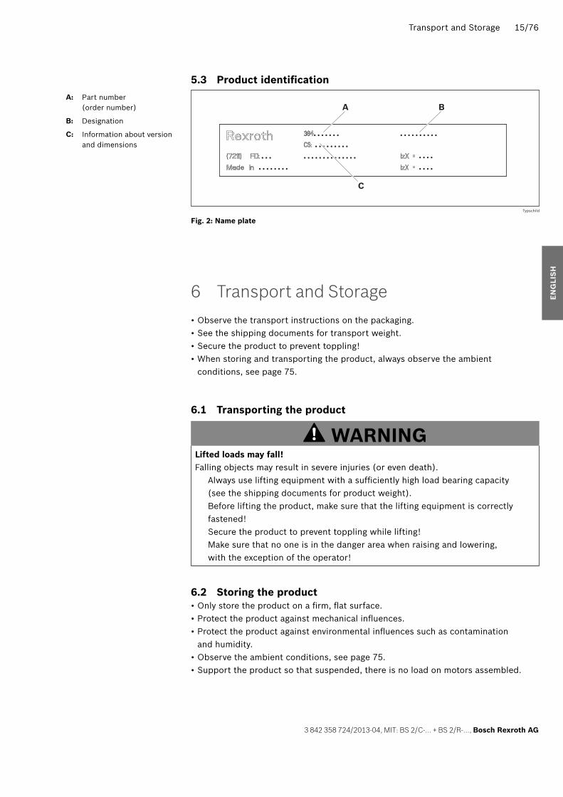
5.3 Product identifi cation
Fig. 2: Name plate
6 Transport and Storage
• Observe the transport instructions on the packaging. • See the shipping documents for transport weight. • Secure the product to prevent toppling! • When storing and transporting the product, always observe the ambient conditions, see page 75.
6.1 Transporting the product
WARNINGLifted loads may fall!Falling objects may result in severe injuries (or even death). Always use lifting equipment with a suffi ciently high load bearing capacity
(see the shipping documents for product weight). Before lifting the product, make sure that the lifting equipment is correctly
fastened! Secure the product to prevent toppling while lifting! Make sure that no one is in the danger area when raising and lowering,
with the exception of the operator!
6.2 Storing the product • Only store the product on a fi rm, fl at surface. • Protect the product against mechanical infl uences. • Protect the product against environmental infl uences such as contamination and humidity.
• Observe the ambient conditions, see page 75. • Support the product so that suspended, there is no load on motors assembled.
. . . . . . . . . . . . . . . . .
. . . .
. . . .
. . . . . . . . .. . . . . . . . . . . . . .. . .
. . . . . . . .
A
C
B
Typschild
A: Part number(order number)
B: Designation
C: Information about version and dimensions
EN
GLI
SH
358724_2013_04_EN.indd 15358724_2013_04_EN.indd 15 27.05.2013 13:07:5527.05.2013 13:07:55

16/76 Assembly
Bosch Rexroth AG, MIT: BS 2/C-… + BS 2/R-…, 3 842 358 724/2013-04
7 Assembly
7.1 Unpacking Lift the product out of the packaging. Dispose of the packaging in accordance with the currently applicable national
regulations in your country.
7.2 Installation requirements When installing the product, always observe the ambient conditions specifi ed
in the Technical Data (see page 75).
7.2.1 Mounting orientation The product should be aligned and level at right angles and parallel to the axis.
This ensures correct functioning and prevents premature wear.
7.2.2 Mounting with T-bolts Mount the transfer systems TS 1, TS 2plus, TS 2pv, TS 4plus, TS 5 and chain
conveyor systems VarioFlow and VarioFlow S with T-bolts and fl ange nuts. Make sure the T-bolt is in the correct position when inserting and tightening
in the slot. The notch at the end of the bolt indicates the T-bolt orientation. 1 = T-bolt insertion orientation in the slot. 2 = T-bolt clamping position in the slot.
Maximum tightening torque: 25 Nm.
7.3 Required tools Hexagon wrenches (open-end):
WS8, WS10, WS13, WS19, WS24. Hex socket wrench: WS4. Water level Combination pliers Flat smooth fi le
21
358724_2013_04_EN.indd 16358724_2013_04_EN.indd 16 27.05.2013 13:07:5527.05.2013 13:07:55

Assembly 17/76
3 842 358 724/2013-04, MIT: BS 2/C-… + BS 2/R-…, Bosch Rexroth AG
7.4 Required accessories • Leg sets to carry the belt section. Note: Support the belt section in the direct vicinity of the drive and return unit. The distance between two leg sets must not exceed 2000 mm. – For BS 2/C-100, BS 2/C-250, BS 2/R-300, BS 4/R-300, BS 2/R-700, BS 4/R-700:SZ 2, 3 842 999 816SZ 2/U, 3 842 999 817SZ 2/T, 3 842 999 818 – For BS 2/C-H, BS 2/R-H, BS 2/R-V:SZ 2-H, 3 842 998 235SZ 2/U-H, 3 842 9998 236SZ 2/T-H, 3 842 998 237
• To fasten the leg sets to the fl oor, each connection requires: – 1x foundation bracket, 3 842 146 815 – 1x dowel, 3 842 526 560 – 2x T-bolts, 3 842 528 718 – 2x fl ange nuts, 3 842 345 081
• Connection kits for the transverse conveyor when using the belt section in lateral transverse transport (drive head to section). – BS 2/C-100, BS 2/C-250, BS 2/R-300, BS 4/R-300, BS 2/R-700, BS 4/R-700 with:ST 2/B, ST 2/B-100, ST 2/C-100, ST 2/R-100, 3 842 528 192 – BS 2/C-400, BS 2/C-700, BS 2/R-1200, BS 2/R-2200 with:ST 2/B, ST 2/B-100, ST 2/C-100, ST 2/R-100, 3 842 518 828 – BS 2/C-H, BS 2/R-H, BS 2/R-V with:ST 2/C-H, ST 2/R-H, ST 2/R-V, 3 842 530 868
• Connection kits for the longitudinal conveyor (drive head to return unit) – BS 2/C-100, BS 2/C-250, BS 2/R-300, BS 4/R-300, BS 2/R-700, BS 4/R-700 with:BS 2/C-100, BS 2/C-250, BS 2/R-300, BS 4/R-300, BS 2/R-700, BS 4/R-700, 3 842 529 881 – BS 2/C-400, BS 2/C-700, BS 2/R-1200, BS 2/R-2200BS 2/C-H, BS 2/R-H, BS 2/R-V with:BS 2/C-100, BS 2/C-250, BS 2/R-300, BS 4/R-300, BS 2/R-700, BS 4/R-700 BS 2/C-400, BS 2/C-700, BS 2/R-1200, BS 2/R-2200BS 2/C-H, BS 2/R-H, BS 2/R-V, 3 842 530 871
EN
GLI
SH
358724_2013_04_EN.indd 17358724_2013_04_EN.indd 17 27.05.2013 13:07:5527.05.2013 13:07:55

18/76 Assembly
Bosch Rexroth AG, MIT: BS 2/C-… + BS 2/R-…, 3 842 358 724/2013-04
7.5 Symbols usedTable 6: Symbols used
21Connect with T-bolt and fl ange nut.Make sure the T-bolt is in the correct position when inserting and tightening in the slot. The notch at the end of the bolt indicates the T-bolt orientation.1 = T-bolt insertion orientation in the slot.2 = T-bolt clamping position in the slot.Maximum tightening torque: 25 Nm.
MD
SW13
= 20Nm
Wrench for hexagonal screwSW = wrench size (WS) … mmMD = required tightening torque … Nm
MD = 8Nm
SW5
Wrench for hex-socket screwSW = wrench size (WS) … mmMD = required tightening torque … Nm
PH3PZ2
Screwdriver for recessed head screwsPZ … = Pozidriv recessed head, size …PH … = Phillips recessed head, size …
Lubricate with Structovis GHD, 0 842 904 229.
gleitmo 585 K Anti-Seize
Grease/grease with specifi ed lubricant: • gleitmo 585 K: gleitmo 585 K, www.fuchs-lubritech.com • Anti-Seize: Food Grade Anti-Seize/Loctite 8014, www.henkel.com
Loctite 243 Loctite 601
Secure the screws with: • Loctite 243: medium strength adhesive (detachable), www.loctite.de • Loctite 601: high strength adhesive (permanent), www.loctite.de
The identifi ed parts are not required for the assembly situation described. Use the parts in another application or dispose of them.
21 3Sequence of assembly steps in the graphics. The numbers correspond with the order of the assembly steps according to the instructions in the accompanying text.
A B C XDesignation of components in graphics. The letters identify the components specifi ed in the instructions.
358724_2013_04_EN.indd 18358724_2013_04_EN.indd 18 27.05.2013 13:07:5527.05.2013 13:07:55

Assembly 19/76
3 842 358 724/2013-04, MIT: BS 2/C-… + BS 2/R-…, Bosch Rexroth AG
7.6 Assembling the product
7.6.1 Assembling the belt section on leg sets
Fig. 3:
SW13 M = 25 NmD
BS 2/...
547 601-02
SZ 2
SZ 2
Assembling the belt section on leg sets (1/2)
1. Assemble the belt section on 2 to 4 leg sets.
Note: • Assemble one leg set each in the direct vicinity of the drive and return unit.
• Assemble the leg sets under the cross connectors of the belt section.
• Maximum distance between 2 leg sets: 2000 mm.
EN
GLI
SH
358724_2013_04_EN.indd 19358724_2013_04_EN.indd 19 27.05.2013 13:07:5527.05.2013 13:07:55

20/76 Assembly
Bosch Rexroth AG, MIT: BS 2/C-… + BS 2/R-…, 3 842 358 724/2013-04
Fig. 4:
SW13
Ø 8
73
M = 25 NmD
3 842 528 718
3 842 146 815
3 842 526 560
SZ 2
SZ 2
1
3.1
3.2
3 842 345 081
SW13 M = 25 NmD
SW24 M = 25 NmD
"A"
BS 2/...
2
547 601-03
Assembling the belt section on leg sets (2/2)
2. Align the belt section at the same height and level as the adjacent components.
3. Bolt the belt section to the fl oor. The following is required per connection: – 1x foundation bracket, 3 842 146 815 – 1x dowel, 3 842 526 560 – 2x T-bolts, 3 842 528 718 – 2x fl ange nuts, 3 842 345 081
358724_2013_04_EN.indd 20358724_2013_04_EN.indd 20 27.05.2013 13:07:5627.05.2013 13:07:56
Assembly 21/76
3 842 358 724/2013-04, MIT: BS 2/C-… + BS 2/R-…, Bosch Rexroth AG
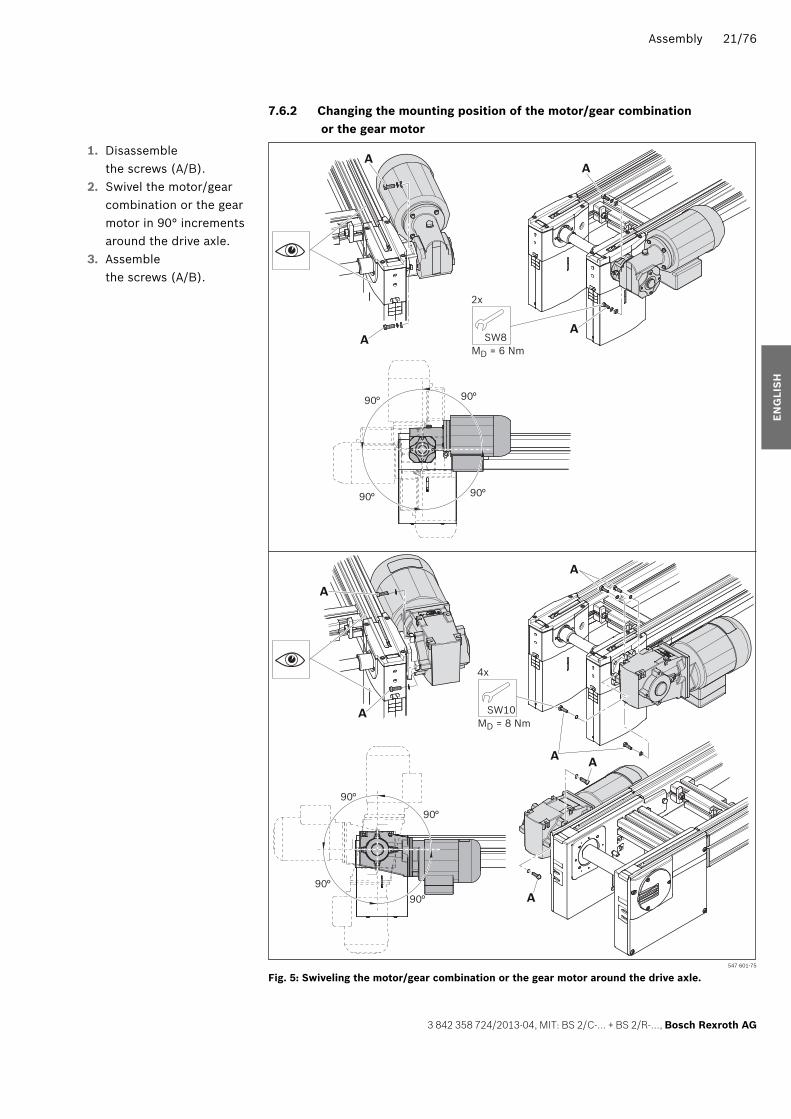
7.6.2 Changing the mounting position of the motor/gear combination or the gear motor
Fig. 5: 547 601-75
SW10
4x
90
MD = 8 Nm
90
9090
9090
90 90
SW8
2x
MD = 6 Nm
A
A
A
A
A
A A
A
A
A
Swiveling the motor/gear combination or the gear motor around the drive axle.
1. Disassemble the screws (A/B).
2. Swivel the motor/gear combination or the gear motor in 90° increments around the drive axle.
3. Assemble the screws (A/B).
EN
GLI
SH
358724_2013_04_EN.indd 21358724_2013_04_EN.indd 21 27.05.2013 13:07:5627.05.2013 13:07:56
22/76 Assembly
Bosch Rexroth AG, MIT: BS 2/C-… + BS 2/R-…, 3 842 358 724/2013-04
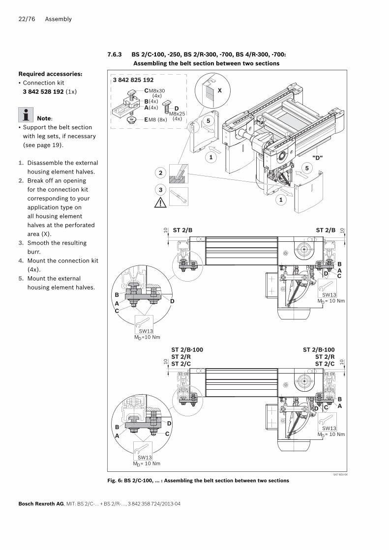
7.6.3 BS 2/C-100, -250, BS 2/R-300, -700, BS 4/R-300, -700: Assembling the belt section between two sections
Fig. 6:
X
5
1
1
2
3
"D"
5
M8x25(4x)
D(4x)
(4x)(4x)
M8 (8x)
M8x30
E
BA
C
3 842 825 192
BA D
SW13 M =10 NmD
SW13 M = 10 NmD
C
BA
D
D
C
C
10
ST 2/B-100ST 2/RST 2/C
ST 2/B-100ST 2/RST 2/C
ST 2/B ST 2/B
101010
BA
SW13 M = 10 NmD
SW13 M = 10 NmD
BAD C
547 601-04
BS 2/C-100, … : Assembling the belt section between two sections
Required accessories: • Connection kit 3 842 528 192 (1x)
Note: • Support the belt section with leg sets, if necessary (see page 19).
1. Disassemble the external housing element halves.
2. Break off an opening for the connection kit corresponding to your application type on all housing element halves at the perforated area (X).
3. Smooth the resulting burr.
4. Mount the connection kit (4x).
5. Mount the external housing element halves.
358724_2013_04_EN.indd 22358724_2013_04_EN.indd 22 27.05.2013 13:07:5627.05.2013 13:07:56

Assembly 23/76
3 842 358 724/2013-04, MIT: BS 2/C-… + BS 2/R-…, Bosch Rexroth AG
7.6.4 BS 2/C-H, BS 2/R-H, BS 4/R-V-1200: Assembling the belt section between two sections
Fig. 7:
SW10MD = 8 Nm
M
4x
D= 7 NmSW4
10ST 2/C-HST 2/R-HST 2/R-V
ST 2/C-HST 2/R-HST 2/R-V
6
52
1
3 3
M
4x
D= 7 NmSW4
43
25
547 601-05
M8x20(4x)
M8x25(4x)
M8(4x)
M8(12x)
4x4x
4x
8x4x
3 842 530 8683 842 518 828M8x50
(4x)M8x25
(4x)
SW13MD = 25 Nm
SW13MD = 25 Nm
BS 2/C-H, … : Assembling the belt section between two sections
Required accessories: • Connection kit 3 842 518 828 (0.5x)
• Connection kit 3 842 530 868 (0.5x)
Note: • Support the belt section with leg sets, if necessary (see page 19).
1. Dismount the gear motor.
2. Disassemble the side cover plates.
3. Mount the connection kit 3 842 518 828 (2x).
4. Mount the connection kit 3 842 530 868 (2x).
5. Mount the side cover plates.
6. Mount the gear motor.
EN
GLI
SH
358724_2013_04_EN.indd 23358724_2013_04_EN.indd 23 27.05.2013 13:07:5727.05.2013 13:07:57

24/76 Assembly
Bosch Rexroth AG, MIT: BS 2/C-… + BS 2/R-…, 3 842 358 724/2013-04
7.6.5 BS 2/R-H, reversible: Assembling the belt section between two sections
Fig. 8:
10
ST 2/R-HST 2/R-V ST 2/R-H
5
6
4
4
8
8
2
9
10
1
SW10MD = 8 Nm
M8x20(4x)
M8x25(4x)
M8(4x)
4x4x
4x
3 842 518 828
M8x25(4x)
D(4x)
(4x)(4x)
M8 (8x)
M8x30
E
BA
C
3 842 825 192
73
SW13MD = 25 Nm
SW13MD = 25 Nm
X
547 601-06
M
4x
D= 7 NmSW4
BS 2/R-H, reversible: Assembling the belt section between two sections
Required accessories: • Connection kit 3 842 518 828 (0.5x)
• Connection kit 3 842 528 192 (0.5x)
1. Dismount the gear motor.
2. Disassemble the side cover plates.
3. Mount the connection kit 3 842 518 828 (2x).
4. Disassemble the external housing element halves.
5. Break off an opening for the connection kit corresponding to your application type on all housing element halves on the perforated area (X).
6. Smooth the resulting burr.
7. Mount the connection kit 3 842 528 192 (2x).
8. Mount the external housing element halves.
9. Mount the side cover plates.
10. Mount the gear motor.
358724_2013_04_EN.indd 24358724_2013_04_EN.indd 24 27.05.2013 13:07:5827.05.2013 13:07:58

Assembly 25/76
3 842 358 724/2013-04, MIT: BS 2/C-… + BS 2/R-…, Bosch Rexroth AG
7.6.6 BS 2/C-100, -250, BS 2/R-300, -700, BS 4/R-300, -700: Assembling two belt sections, drive head to return unit
Fig. 9: 547 601-72
3 842 529 881
52
MD= 15 NmSW5
==
5
2
2
4
4
1
3
3 51
BS 2/C-100, … : Assembling two belt sections, drive head to return unit
Required accessories: • Connection kit 3 842 529 881 (1x)
1. Disassemble the external housing element halves.
2. Slide the connection kit into the T-slot on the drive head.
3. Position the return unit of the connecting belt section without gap at the same height and level as the drive head.
4. Mount the connection kit in the center between the drive head and the return unit.
5. Mount the external housing element halves.
EN
GLI
SH
358724_2013_04_EN.indd 25358724_2013_04_EN.indd 25 27.05.2013 13:07:5827.05.2013 13:07:58
26/76 Assembly
Bosch Rexroth AG, MIT: BS 2/C-… + BS 2/R-…, 3 842 358 724/2013-04
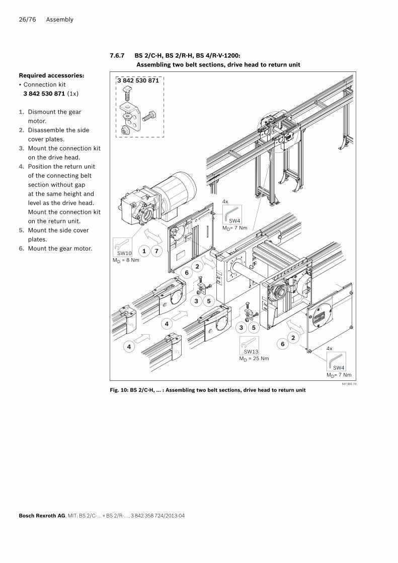
7.6.7 BS 2/C-H, BS 2/R-H, BS 4/R-V-1200: Assembling two belt sections, drive head to return unit
Fig. 10: 547 601-73
3 842 530 871
SW10MD = 8 Nm
M
4x
D= 7 NmSW4
M
4x
D= 7 NmSW4
2
3 5
3
4
5
6
1 7
6
2
SW13MD = 25 Nm
4
BS 2/C-H, … : Assembling two belt sections, drive head to return unit
Required accessories: • Connection kit 3 842 530 871 (1x)
1. Dismount the gear motor.
2. Disassemble the side cover plates.
3. Mount the connection kit on the drive head.
4. Position the return unit of the connecting belt section without gap at the same height and level as the drive head. Mount the connection kit on the return unit.
5. Mount the side cover plates.
6. Mount the gear motor.
358724_2013_04_EN.indd 26358724_2013_04_EN.indd 26 27.05.2013 13:07:5927.05.2013 13:07:59

Assembly 27/76
3 842 358 724/2013-04, MIT: BS 2/C-… + BS 2/R-…, Bosch Rexroth AG
7.6.8 Checking the chain elongationBS 2/C-100, -250, BS 2/R-300, -700, BS 4/R-300, -700
Fig. 11:
1,5 +0,5
A
B
E
D
C
547 601-07
Checking the chain elongation, “small” drive head
You can check the elongation of the chain through the slot (A) in the housing element. The lever of the chain tensioner moves down as the chain length increases, from top (new/short chain) to bottom (elongated chain). The chain must be shortened once the lever in the slot is no longer visible.
As an alternative, mount a proximity switch (E, ø8 mm, max. length incl. the turn radius of the cable: 45 mm) in the fastening clip.Switch distance: 1.5 + 0.5 mmThe tab (C) activates the proximity switch when the max. admissible chain elongation is reached.
Note: • Always observe the switch distance, otherwise the proximity switch will be mechanically destroyed.
• Lead the cable through the break in the housing element to the control unit.
EN
GLI
SH
358724_2013_04_EN.indd 27358724_2013_04_EN.indd 27 27.05.2013 13:07:5927.05.2013 13:07:59

28/76 Assembly
Bosch Rexroth AG, MIT: BS 2/C-… + BS 2/R-…, 3 842 358 724/2013-04
7.6.9 Checking the chain elongationBS 2/C-H, BS 2/R-H, BS 4/R-V-1200
Fig. 12:
1,5+0,5
SH 2/UV
547 601-30
X
Checking the of chain elongation, “large” drive head
You can check the elongation of the chain based on the state of the tension lever (X) of the chain tensioner. The tension lever (X) moves down as the chain length increases, from top (new/short chain) to bottom (elongated chain). The chain must be shortened once the tension lever (X) is in the lowest position.
As an alternative, mount a proximity switch to query the lowest position of the tension lever (X). • SH 2/UV switch bracket, 3 842 168 600.
• Proximity switch, 3 842 537 995.
358724_2013_04_EN.indd 28358724_2013_04_EN.indd 28 27.05.2013 13:08:0027.05.2013 13:08:00

Assembly 29/76
3 842 358 724/2013-04, MIT: BS 2/C-… + BS 2/R-…, Bosch Rexroth AG
7.6.10 BS 2/R-300, -700, BS 4/R-300, -700: Assembling the accelerating element (only if lWT = 160/240)
For short, light workpiece pallets (lWT = 160, 240) it may be required to ensure they pass of the conveyor trench by installing an acceleration elements.
Fig. 13: 547 601-09
5
4
SW10
BS 2/R-700BS 2/R-300
1
1
2)
6
4
2
3
7
3
8
SW19
3
SW10 M = 8 NmD
M = 8 NmD
4x2x
Assemble acceleration element (1/2)
Note:Perform the work steps on both sides at the same time.
1. Dismount the gear motor.
2. Remove the external housing element halves.
3. Turn the drive shaft with the help of a wrench in the transport direction until the master link appears on the chain tensioner.
The master link of the accumulation roller chain can be recognized through the galvanized link plate 2).4. Pull the chain tensioner
upwards3) and secure it in its fi nal position with a pin or a screwdriver.
3) BS…, reversible: unlatch the chain tensioner by lifting the “latches” Fig. 13, pos. 4.
5. Open the chain at the master link.
6. Disassemble the covers on the drive head.
7. Pull the chain back until the slider is exposed in the drive head.
8. Clip the acceleration element onto the slider.
EN
GLI
SH
358724_2013_04_EN.indd 29358724_2013_04_EN.indd 29 27.05.2013 13:08:0027.05.2013 13:08:00

30/76 Assembly
Bosch Rexroth AG, MIT: BS 2/C-… + BS 2/R-…, 3 842 358 724/2013-04
Fig. 14: 547 601-10
11
3 842 530 417
18
12
13
9
BS 2/R-700BS 2/R-300
SW19
10
10
SW10
14
14SW10
M = 8 NmDM = 8 NmD
4x2x
Assembling the acceleration element (2/2)
9. Pull the chain in the top guide profi le up to the drive head.
10. Position the chain on the drive wheel. Turn the drive wheels in the transport direction until the chain appears on the chain tensioner.
11. Close the chain.12. Release the chain
tensioner. Check the tension of the chain.
13. Mount the external housing element halves.
14. Assemble the gear motor.
Note: • Avoid accumulation over the acceleration element! Accumulation over the acceleration element causes heavy wear on the rollers and shortens the lifespan of the chain.
358724_2013_04_EN.indd 30358724_2013_04_EN.indd 30 27.05.2013 13:08:0027.05.2013 13:08:00

Assembly 31/76
3 842 358 724/2013-04, MIT: BS 2/C-… + BS 2/R-…, Bosch Rexroth AG
7.6.11 Electrically connecting the product
WARNINGHigh electrical voltage!Danger of severe injuries or death due to electric shock. Make sure the relevant system component is not under pressure or voltage
before performing any maintenance or repair work. Protect the system against being switched on.
• Select the control and sensor elements in accordance with EN ISO 13849. Observe the load to be conveyed and the transportation speed.
• Only trained specialists are permitted to connect the motor! • Observe regulation VDE 0100 for Germany or the appropriate regulations for the country where the product is used.
Motor connection • Note the existing line voltage! • Note the electrical connection parameters on the motor rating plate, see Fig. 15 on page 32.
• Connect the motor as a Y-connection or a delta connection in accordance with the connection plans, see Fig. 16 on page 32 and the connection plan in the terminal box.
• The motor is equipped with a bi-metal switch (potential-free thermal contact, 230 V AC, 300 mA) to monitor the temperature. Connect the motor in such a manner that it becomes currentless when the switch is actuated.
• Select a cable entry that prevents damage to the cable during operation. • Connection cable option: 3 842 409 645, see Fig. 17 on page 32. Pay attention to the ballast fuse!
Checking the motor’s rotational direction • Start the system for a maximum of 2 s and check that the motor is rotating in the correct direction.
• Exchange any two wires (L1, L2, or L3, see Fig. 16 on page 32) to change the motor’s rotational direction.
Note:In motors with a factory-installed plug, correct the rotational direction in the switch cabinet or at the plug coupling (socket side). This will simplify exchanges.
EN
GLI
SH
358724_2013_04_EN.indd 31358724_2013_04_EN.indd 31 27.05.2013 13:08:0127.05.2013 13:08:01

32/76 Assembly
Bosch Rexroth AG, MIT: BS 2/C-… + BS 2/R-…, 3 842 358 724/2013-04
Fig. 15: Motor rating plate (example)
Fig. 16: Connection plans: delta connection/Y-connection
Fig. 17: Connection cable option
Installation_A
TW1 TW2 PE
T1 T2
1U2 1V2 1W2 1U2 1V2 1W2
1U1 1V1 1W1 1U1 1V1 1W1
2U1 2V1 2W1 2U1 2V1 2W1
PE
U1 V1 W1
TW1 TW2 PE
T1 T2 PE
U1 V1 W1
Installation_DY
3 842 409 645
Installation_C
3 842 409 645
L = 400 mm
L = 400 mm
358724_2013_04_EN.indd 32358724_2013_04_EN.indd 32 27.05.2013 13:08:0127.05.2013 13:08:01

Commissioning 33/76
3 842 358 724/2013-04, MIT: BS 2/C-… + BS 2/R-…, Bosch Rexroth AG
8 Commissioning
8.1 Commissioning for the fi rst time
CAUTIONUnexpected movements, falling workpiece pallets Injuries due to falling objects. Before commissioning, make sure that the product has been correctly assembled
by qualifi ed personnel (see page 9).
NOTICEMalfunctions due to incorrect assembly and commissioningThe product may be damaged or its service life shortened. Commissioning requires basic mechanical, pneumatic, and electrical knowledge. The product may only be commissioned by qualifi ed personnel (see page 9).
Conveyor chain malfunction (fl at top chain/accumulation roller chain)Lack of lubrication will lead to conveyor chain malfunctions and can lead to a crash. There is a danger of damage to property. Lubricate the conveyor chain before comissioning and afterwards every 1000 h
with Structovis GHD, 0 842 904 229, see pages 39, 40. Lubricate the conveyor chain after downtimes > 6 months (e.g. if set-up took
a very long time or if the system was temporarily decommissioned).
• Perform a risk assessment in accordance with DIN EN ISO 12100 before initial commissioning or recommissioning of a conveyor system.
• According to EU Machinery Directive 2006/42/EC, you must provide the transfer system with an EMERGENCY STOP command device.
• The surfaces of motors and gears can reach temperatures of over 65°C under certain load and operating conditions. In such cases, the valid accident prevention regulations (in Germany: UVV) must be met by corresponding constructive measures (safety devices) or safety warning signs!
• Make sure that all electrical and pneumatic connections are either used or covered. Check to see that all threaded and push-in fi ttings are securely mounted. All relevant protective covers must be in place.
• Continuous conveyors that are in motion or operation may only be inspected or adjusted if protective devices are present and correctly positioned.
• Observe DIN EN ISO 13857 when removing or replacing protective devices and/or deactivating safety devices.
• Test runs with open housings are only permitted when they are performed by skilled workers using hold-to-run controls and when the infl uence of all other switching devices can be excluded.
• Only commission the belt section if all safety devices have been installed in the system and are functional.
• Commission the product only if it is installed completely.
EN
GLI
SH
358724_2013_04_EN.indd 33358724_2013_04_EN.indd 33 27.05.2013 13:08:0127.05.2013 13:08:01

34/76 Commissioning
Bosch Rexroth AG, MIT: BS 2/C-… + BS 2/R-…, 3 842 358 724/2013-04
8.2 Residual hazardsTable 7: Residual hazards
Location Situation Hazard Measure
1 Infeed point for conveyor medium
Drawing in of clothing or long hair
Crushing, tearing hair out
Do not reach into the system during operation. Wear suitable protective clothing.
2 Cross connector; drive shaft:Between component and workpiece pallet
Catching of body parts Cutting off Do not reach into the system during operation. Design solutions are necessary in the service area and at transport speeds v > 15 m/min, e.g. a protective fence.
3 Conveyor medium: Between running conveyor medium and standing workpiece pallet (e.g. during separation)
Catching of body parts Crushing Do not reach into the system during operation.
4 Between workpiece pallet and workpiece pallet
Crushing of body parts Crushing Do not reach into the system during operation. Design solutions are necessary in the service area and at transport speeds of v > 15 m/min, e.g. separation of workpiece pallets.
5 End of the belt section Crushing of body parts due to falling parts
Crushing Design solution required, e.g. stopper
1
3
4
2
5
8.3 Recommissioning after shutdownsFollow the same procedure used for initial commissioning.
358724_2013_04_EN.indd 34358724_2013_04_EN.indd 34 27.05.2013 13:08:0127.05.2013 13:08:01
Operation 35/76
3 842 358 724/2013-04, MIT: BS 2/C-… + BS 2/R-…, Bosch Rexroth AG
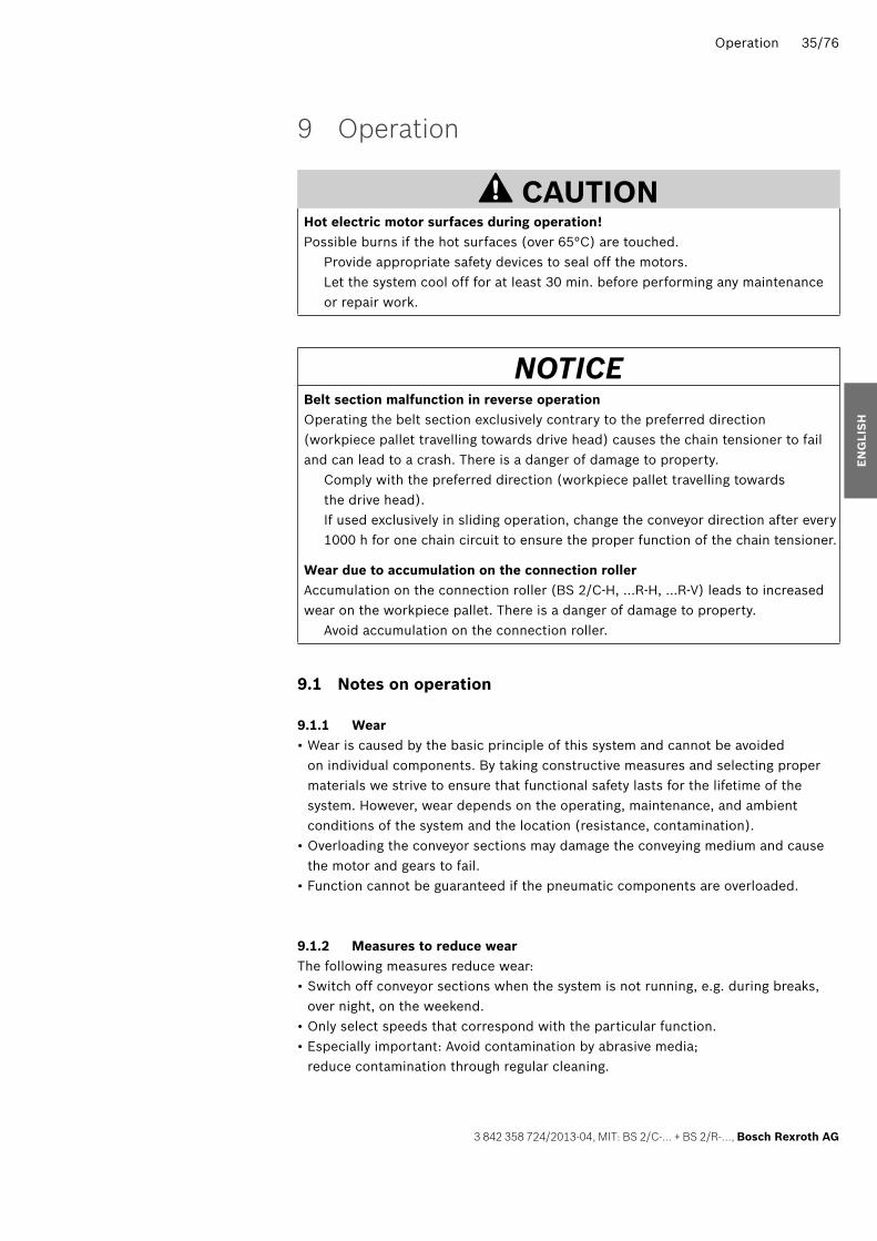
9 Operation
CAUTIONHot electric motor surfaces during operation! Possible burns if the hot surfaces (over 65°C) are touched. Provide appropriate safety devices to seal off the motors. Let the system cool off for at least 30 min. before performing any maintenance
or repair work.
NOTICEBelt section malfunction in reverse operationOperating the belt section exclusively contrary to the preferred direction (workpiece pallet travelling towards drive head) causes the chain tensioner to fail and can lead to a crash. There is a danger of damage to property. Comply with the preferred direction (workpiece pallet travelling towards
the drive head). If used exclusively in sliding operation, change the conveyor direction after every
1000 h for one chain circuit to ensure the proper function of the chain tensioner.
Wear due to accumulation on the connection rollerAccumulation on the connection roller (BS 2/C-H, …R-H, …R-V) leads to increased wear on the workpiece pallet. There is a danger of damage to property. Avoid accumulation on the connection roller.
9.1 Notes on operation
9.1.1 Wear • Wear is caused by the basic principle of this system and cannot be avoided on individual components. By taking constructive measures and selecting proper materials we strive to ensure that functional safety lasts for the lifetime of the system. However, wear depends on the operating, maintenance, and ambient conditions of the system and the location (resistance, contamination).
• Overloading the conveyor sections may damage the conveying medium and cause the motor and gears to fail.
• Function cannot be guaranteed if the pneumatic components are overloaded.
9.1.2 Measures to reduce wearThe following measures reduce wear: • Switch off conveyor sections when the system is not running, e.g. during breaks, over night, on the weekend.
• Only select speeds that correspond with the particular function. • Especially important: Avoid contamination by abrasive media; reduce contamination through regular cleaning.
EN
GLI
SH
358724_2013_04_EN.indd 35358724_2013_04_EN.indd 35 27.05.2013 13:08:0227.05.2013 13:08:02

36/76 Operation
Bosch Rexroth AG, MIT: BS 2/C-… + BS 2/R-…, 3 842 358 724/2013-04
9.1.3 Loading the workpiece palletWhen setting up and testing the modular units, the workpieces pallets should not all have the same weight on the conveyor sections. Full and empty pallets should all come through the circuit. Extreme differences in weight may, however, require special measures to avoid functional disruptions. This applies to: • Permissible accumulation length before stop gates. • Damper function. • Dampened stop gates.
9.1.4 Ambient infl uences • Resistant to many common media used in production such as water, mineral oil, grease, and detergents. Contact your Rexroth representative if you have any doubts about resistance to specifi c chemicals, such as test oil, doped oils, aggressive detergents, solvents, or brake fl uid.
• Avoid long-term contact with strong acidic or basic reacting materials. • Wear may increase dramatically if the system is contaminated due to environmental factors, particularly with abrasive media such as sand and silicates, but also due to processes running on the transfer system (e.g. welding beads, pumice dust, glass shards, shavings, or lost parts…). In such cases, maintenance intervals should be substantially shortened.
• Resistance to media and contamination does not mean that functional safety is guaranteed in every case. – Liquids that thicken on evaporation and are highly viscous or adhesive (sticky) could lead to a disruption in function. – Media with lubricating properties may reduce the driving power that is caused by friction if they are carried over onto systems with rollers.
Such cases require special attention when planning the system and the maintenance intervals need to be shortened accordingly.
358724_2013_04_EN.indd 36358724_2013_04_EN.indd 36 27.05.2013 13:08:0227.05.2013 13:08:02

Maintenance and Repair 37/76
3 842 358 724/2013-04, MIT: BS 2/C-… + BS 2/R-…, Bosch Rexroth AG
10 Maintenance and Repair
WARNINGHigh electrical voltage!Danger of severe injuries or death due to electric shock. Make sure the relevant system component is not under pressure or voltage
before performing any maintenance or repair work. Protect the system against being switched on.
High pneumatic pressure!Danger of severe injuries or death. Switch off the compressed air supply on the relevant system component before
performing any maintenance or repair work. Protect the system against being switched on.
CAUTIONHot electric motor surfaces during operation!Possible burns if the hot surfaces (over 65°C) are touched. Provide appropriate safety devices to seal off the motors. Let the system cool off for at least 30 min. before performing any maintenance
or repair work.
• Continuous conveyors that are in motion or operation may only be inspected or adjusted if protective devices are present and correctly positioned.
• Observe DIN EN ISO 13857 when removing or replacing protective devices and/or deactivating safety devices.
• Test runs with open housings are only permitted when they are performed by skilled workers using hold-to-run controls and when the infl uence of all other switching devices can be excluded.
EN
GLI
SH
358724_2013_04_EN.indd 37358724_2013_04_EN.indd 37 27.05.2013 13:08:0227.05.2013 13:08:02

38/76 Maintenance and Repair
Bosch Rexroth AG, MIT: BS 2/C-… + BS 2/R-…, 3 842 358 724/2013-04
10.1 Cleaning and care
NOTICEBearing malfunctionsMoistening of the bearings with grease-dissolving substances, e.g. for cleaning purposes, will lead to bearing malfunctions. There is a danger of damage to property; the service life may be shortened. Keep grease-dissolving or aggressive cleaning agents away from the bearings! Only use a slightly damp cloth to clean the product.
Conveyor chain malfunction (fl at top chain/accumulation roller chain)Lack of lubrication or moistening of the conveyor chain with grease-dissolving substances, e.g. for cleaning purposes, will lead to conveyor chain malfunctions and can lead to a crash. There is a danger of damage to property. Always comply with the maintenance intervals. Maintain a maintenance schedule. Keep grease-dissolving or aggressive cleaning agents away from the conveyor
chain! Only use a slightly damp cloth to clean the product.
10.2 Inspection
10.2.1 Conveyor chain (fl at top chain/accumulation roller chain)Conduct regular visual inspections of the conveyor chain for wear and suffi cient lubrication.
10.3 Maintenance
10.3.1 BearingsAll bearings are provided with lifelong lubrication and are maintenance-free under normal conditions.
10.3.2 GearsThe gears are maintenance-free.
10.3.3 MotorTo ensure adequate motor cooling, dirt and dust must be removed at regular intervals from the: • Motor surface • Fan housing inlets • Interior surfaces of the cooling fi ns
The cleaning intervals are based on the ambient conditions and operating conditions.
358724_2013_04_EN.indd 38358724_2013_04_EN.indd 38 27.05.2013 13:08:0227.05.2013 13:08:02

Maintenance and Repair 39/76
3 842 358 724/2013-04, MIT: BS 2/C-… + BS 2/R-…, Bosch Rexroth AG
10.3.4 Conveyor chain (fl at top chain/accumulation roller chain)The conveyor chain used in this product has already been lubricated at the factory before delivery.Before commissioning for the fi rst time, lubricate the conveyor chain with 1 to 2 g oil per chain meter, and afterwards every 1000 operating hours with 2 to 3 g oil/m, using Structovis GHD (0 842 904 229).For system-related reasons, the lubricant can spread.
*)*)
Flat top chains Accumulation roller chain Vplus accumulation roller chainFig. 18: Lubrication points
*) Also lubricate the fl at top chain on the side (in curves and sections).
NOTE! Always comply with the maintenance intervals, as a lack of lubrication will result
in operational disruptions due to a chain malfunction, up to a system crash with substantial damage to property.
Maintain a maintenance schedule. The running times during set-up and commissioning of the system count as a part
of the fi rst maintenance interval. If you do not know how long the system ran during set-up and commissioning,
lubricate the conveyor chain before starting production. Lubricate the chain after downtimes > 6 months (e.g. if set-up took a very long
time or if the system was temporarily decommissioned). Before lubricating the chain, clean off any excess grease, dirt, or other
contamination. While doing so, also check the conveyor chain for wear and elongation.
We recommend: The LU 2 automatic lubrication unit enables an optimally defi ned, uniform lubrication of the conveyor chain during operation. See page 41.
EN
GLI
SH
358724_2013_04_EN.indd 39358724_2013_04_EN.indd 39 27.05.2013 13:08:0227.05.2013 13:08:02

40/76 Maintenance and Repair
Bosch Rexroth AG, MIT: BS 2/C-… + BS 2/R-…, 3 842 358 724/2013-04
10.3.5 Options to lubricate the conveyor chain manually
BS 2/C-100, ..C-250 BS 2/R-300, ..R-700
MD= 7 NmSW4
MD= 7 NmSW4
BS 2/C-400, ..C-H BS 2/R-H, ..R-V-1200Fig. 19: Lubricating the conveyor chain in the drive module
MD= 5 NmSW4
MD= 5 NmSW4
ST 2/C-W ST 2/R-WFig. 20: Lubricating the conveyor chain in the maintenance section
358724_2013_04_EN.indd 40358724_2013_04_EN.indd 40 27.05.2013 13:08:0227.05.2013 13:08:02

Maintenance and Repair 41/76
3 842 358 724/2013-04, MIT: BS 2/C-… + BS 2/R-…, Bosch Rexroth AG
10.3.6 LU 2 automatic lubrication unitThe LU 2 automatic lubrication unit enables chain lubrication during operation. The chain can only be lubricated at the drive module.The LU 2 automatic lubrication unit consists of the following components: • LU 2 lubrication unit, 3 842 543 482 • LC 2 oil container, 3 842 543 469 • AS 2/C-100, -250 adapter set, 3 842 543 483 1) • AS 2/C-400, adapter set, 3 842 543 484 • AS 2/R-300, -700 adapter set, 3 842 543 485 1) • AS 2/R-1200, -2200 adapter set, 3 842 543 486 • AS 2/R-V-1200 adapter set, 3 842 543 487
1) An additional LU 2 retrofi t kit 3 842 546 725 is required for retrofi tting older transfer systems without lube hole.
LU 2 AS 2/C-100, AS 2/C-250 AS 2/C-400, AS 2/C-700
LU 2
LC 2
Set AS ... *)
*)
3 842 543 482, LU 2+ 3 842 543 469, LC 2 + 3 842 543 483, AS 2/C-100, -250 set + 3 842 543 484, AS 2/C-400, -700 set
AS 2/R-300, AS 2/R-700 AS 2/R-1200, AS 2/R-2200 AS 2/R-V-1200, AS 2/R-V-2200
*)
*) *)
+ 3 842 543 485, AS 2/R-300, -700 set + 3 842 543 486, AS 2/R-1200, -2200 set + 3 842 543 487, AS 2/R-V set
Fig. 21: LU 2 automatic lubrication unit, overview
The holes identifi ed with *) are used to connect the LU 2 automatic lubrication unit.
EN
GLI
SH
358724_2013_04_EN.indd 41358724_2013_04_EN.indd 41 27.05.2013 13:08:0327.05.2013 13:08:03

42/76 Maintenance and Repair
Bosch Rexroth AG, MIT: BS 2/C-… + BS 2/R-…, 3 842 358 724/2013-04
10.4 Replacing wear parts
10.4.1 DesignationsThis documentation uses the following designations:
Table 8: Designations
Designation Meaning
Chain Conveyor chain with conveyor medium: • Flat top chain (…/C-…) • Accumulation roller chain (…/R-…) • Accumulation roller chain Vplus (…/R-V-…)
10.4.2 Required tools • Hexagon wrenches (open-end):WS8, WS10, WS13, WS19, WS27.
• Hex socket wrenches: WS4.
• Water level • Combination pliers
10.4.3 Required accessories • For the fl at top chain:
– Disassembly tool: 3 842 010 510 – Master link: 3 842 535 333
• For the accumulation roller chain: – Disassembly tool: 3 842 010 511 – Master link: 3 842 530 417
• For the Vplus accumulation roller chain: – Disassembly tool: 3 842 539 357 – Master link: 3 842 538 872
8 981 010 510
3 842 535 3338 981 010 511
3 842 530 417
3 842 539 357
3 842 538 872
Flat top chains Accumulation roller chain Vplus accumulation roller chainFig. 22: Required accessories
358724_2013_04_EN.indd 42358724_2013_04_EN.indd 42 27.05.2013 13:08:0427.05.2013 13:08:04

Maintenance and Repair 43/76
3 842 358 724/2013-04, MIT: BS 2/C-… + BS 2/R-…, Bosch Rexroth AG
10.4.4 Notes for mounting: Finding the master link on a functional chain
CAUTION! Observe DIN EN ISO 13857 when removing or replacing protective devices
and/or deactivating safety devices. Test runs with open housings are only permitted when they are performed
by skilled workers using hold-to-run controls and when the infl uence of all other switching devices can be excluded.
1. On the side without the motor either remove the external housing element half (BS 2/C-100, …-250, BS 2/R-300, …-700, BS 4/R-300, …-700) or unscrew the cover plate on the side (BS 2/C-H, BS 2/R-H, BS 2/R-V-1200).
2. Use the hold-to-run control to run the belt section until the master link appears in the chain tensioner.
The master link can be recognized through: – The gray fl at plate with hole on the gray fl at top chain 1). – The galvanized link plate on the accumulation roller chain 2).
1)
2)
2)
Flat top chains Accumulation roller chain Vplus accumulation roller chainFig. 23: Master link
EN
GLI
SH
358724_2013_04_EN.indd 43358724_2013_04_EN.indd 43 27.05.2013 13:08:0427.05.2013 13:08:04

44/76 Maintenance and Repair
Bosch Rexroth AG, MIT: BS 2/C-… + BS 2/R-…, 3 842 358 724/2013-04
10.4.5 Notes for mounting: securing the chain tensioner forBS 2/C-100, BS 2/C-250, BS 2/R-300, BS 4/R-300, BS 2/R-700, BS 4/R-700
547 601-37
Fig. 24: Securing the chain tensioner: “small” drive head, reversible chain tensioner
10.4.6 Notes for mounting: Securing the chain tensioner forBS 2/C-H, BS 2/R-H, BS 2/R-V-1200
X
547 601-38
X 2
1
3
Fig. 25: Securing the chain tensioner: “large” drive head
BS 2/C…, BS 2/R…: Pull the chain tensioner
upwards and secure it in its fi nal position with a pin or a screwdriver.
BS 2/R…, reversible: Unlatch the chain
tensioner by lifting the “latches” ( Fig. 24). Pull the chain tensioner upwards and secure it in its fi nal position with a pin or a screwdriver.
Pull the chain tensioner (X) upwards and secure it in its fi nal position by turning it 90° clockwise. ( Fig. 25, pos. 2).
Loosen the chain tensioner by turning it 90° counter-clockwise. ( Fig. 25, pos. 3).
358724_2013_04_EN.indd 44358724_2013_04_EN.indd 44 27.05.2013 13:08:0427.05.2013 13:08:04

Maintenance and Repair 45/76
3 842 358 724/2013-04, MIT: BS 2/C-… + BS 2/R-…, Bosch Rexroth AG
10.4.7 Checking the chain elongation forBS 2/C-100, BS 2/C-250, BS 2/R-300, BS 4/R-300, BS 2/R-700, BS 4/R-700
547 601-71
A
B
Fig. 26: Checking the chain elongation for “small” drive head
10.4.8 Checking the chain elongation forBS 2/C-H, BS 2/R-H, BS 2/R-V-1200
547 601-70
X
Fig. 27: Checking the chain elongation for “large” drive head
You can check the elongation of the chain through the slot (A) in the housing element. The lever of the chain tensioner moves down as the chain length increases, from top (new/short chain) to bottom (elongated chain). The chain must be shortened once the lever in the slot is no longer visible. Exchange the chain if the admissible elongation of the chain (= 3% of the original length) is exceeded.
You can check the elongation of the chain based on the state of the tension lever (X) of the chain tensioner. The tension lever (X) moves down as the chain length increases, from top (new/short chain) to bottom (elongated chain). The chain must be shortened once the tension lever (X) is in the lowest position. Exchange the chain if the admissible elongation of the chain (= 3% of the original length) is exceeded.
EN
GLI
SH
358724_2013_04_EN.indd 45358724_2013_04_EN.indd 45 27.05.2013 13:08:0527.05.2013 13:08:05

46/76 Maintenance and Repair
Bosch Rexroth AG, MIT: BS 2/C-… + BS 2/R-…, 3 842 358 724/2013-04
10.4.9 Shortening the conveyor chain: BS 2/C-100, BS 2/R-300, BS 4/R-300, BS 2/C-250, BS 2/R-700, BS 4/R-700motor mounting (MA) = R/L
Fig. 28: 547 601-41
BS 2/R-700BS 2/R-300BS 2/C-250BS 2/C-100
1)
75
3 842 535 333
8 981 010 510
6 2 9
4 8
6
3
SW19
3
SW10
1
1SW10
M = 8 NmDM = 8 NmD
4x2x
Shortening the conveyor chain: BS 2/C-100, …-250, BS 2/R-300, …-700, MA = R/L (1/2)
Note:Perform the work steps on both sides at the same time.
1. Dismount the gear motor.
2. Disassemble the external housing element halves.
3. Turn the drive shaft with the help of a wrench in the transport direction until the master link appears on the chain tensioner.
The master link can be recognized through:
– The gray fl at plate with hole on the gray fl at top chain 1). – The galvanized link plate on the accumulation roller chain 2).
358724_2013_04_EN.indd 46358724_2013_04_EN.indd 46 27.05.2013 13:08:0527.05.2013 13:08:05

Maintenance and Repair 47/76
3 842 358 724/2013-04, MIT: BS 2/C-… + BS 2/R-…, Bosch Rexroth AG
Fig. 29: 547 601-42
2 9
4 8
SW10 10 10
SW10 M = 8 NmD
BS 2/R-700BS 2/R-300BS 2/C-250BS 2/C-100
675
3 842 530 417
8 981 010 511
6
M = 8 NmD
2)
3
SW19
3
4x2x
Shortening the conveyor chain: BS 2/C-100, …-250, BS 2/R-300, …-700, MA = R/L (2/2)
4. Secure the chain tensioner.
5. Open the chain at the master link.
6. With the disassembly tool3) remove enough chain links to be able to close the chain as tightly as possible at the tension wheel.
3) Disassembly tool: – For the fl at top chain: 3 842 010 510 – For the accumulation roller chain: 3 842 010 511
Note: • Remove the same number of chain links from both chains.
• Note the number of chain links removed in the service plan.
• Exchange the chain if the admissible elongation of the chain (= 3% of the original length) is exceeded.
7. Close the chain.8. Release the chain
tensioner. Check the tension of the chain.
9. Mount the external housing element halves.
10. Mount the gear motor.E
NG
LIS
H
358724_2013_04_EN.indd 47358724_2013_04_EN.indd 47 27.05.2013 13:08:0627.05.2013 13:08:06

48/76 Maintenance and Repair
Bosch Rexroth AG, MIT: BS 2/C-… + BS 2/R-…, 3 842 358 724/2013-04
10.4.10 Shorten conveyor chain: BS 2/C-100, BS 2/R-300, BS 4/R-300, motor mounting (MA) = M
Fig. 30: 547 601-43
3
4
1)
3 842 535 333
8 981 010 510
5
7
4
2 6
1
Shortening the conveyor chain: BS 2/C-100, BS 2/R-300, MA = M (1/2)
Note: • An additional master link is required for each chain4).
4) Master link: – For the fl at top chain: 3 842 535 333 – For the accumulation roller chain: 3 842 530 417
• Perform the work steps on both sides at the same time.
1. Disassemble the external housing element halves.
2. Secure the chain tensioner.
3. Open the chain with the disassembly tool3).
3) Disassembly tool: – For the fl at top chain: 3 842 010 510 – For the accumulation roller chain: 3 842 010 511
358724_2013_04_EN.indd 48358724_2013_04_EN.indd 48 27.05.2013 13:08:0627.05.2013 13:08:06

Maintenance and Repair 49/76
3 842 358 724/2013-04, MIT: BS 2/C-… + BS 2/R-…, Bosch Rexroth AG
Fig. 31: 547 601-44
3
4
5
4
2 6
7
1
2)3 842 530 417
8 981 010 511
Shortening the conveyor chain: BS 2/C-100, BS 2/R-300, MA = M (2/2)
4. With the disassembly tool remove enough chain links to be able to close the chain as tightly as possible at the tension wheel.
Note: • Remove the same number of chain links from both chains.
• Note the number of chain links removed in the service plan.
• Exchange the chain if the admissible elongation of the chain (= 3% of the original length) is exceeded.
5. Lubricate the master link and close the chain.
6. Release the chain tensioner. Check the tension of the chain.
7. Mount the external housing element halves.
EN
GLI
SH
358724_2013_04_EN.indd 49358724_2013_04_EN.indd 49 27.05.2013 13:08:0727.05.2013 13:08:07

50/76 Maintenance and Repair
Bosch Rexroth AG, MIT: BS 2/C-… + BS 2/R-…, 3 842 358 724/2013-04
10.4.11 Shortening the conveyor chain: BS 2/C-H, BS 2/R-H, BS 2/R-V-1200, motor mounting (MA) = R/L
Fig. 32: 547 601-45
2
92
7
8
4
8 981 010 510
1)
3 842 535 333
5 6 7
X
"X"
3
M
4x
D= 7 NmSW4
M
4x
D= 7 NmSW4
SW10MD = 8 Nm
SW27
1
BS 2/C-H
Shortening the conveyor chain: BS 2/C-H, BS 2/R-H, BS 2/R-V-1200, MA = R/L (1/2)
Note:Perform the work steps on both sides at the same time.
1. Dismount the gear motor.
2. Disassemble the side cover plates, remove the bottom cover sheets.
3. Turn the drive shaft with the help of a wrench in the transport direction until the master link appears on the chain tensioner.
The master link can be recognized through:
– The gray fl at plate with hole on the gray fl at top chain 1). – The galvanized link plate on the accumulation roller chain 2).
358724_2013_04_EN.indd 50358724_2013_04_EN.indd 50 27.05.2013 13:08:0727.05.2013 13:08:07

Maintenance and Repair 51/76
3 842 358 724/2013-04, MIT: BS 2/C-… + BS 2/R-…, Bosch Rexroth AG
Fig. 33:
2)
X
M
4x
D= 7 NmSW4
SW10MD = 8 Nm
BS 2/R-H BS 2/R-V
2)
3 842 538 872
765
7
94
8
"X"
9
M
4x
D= 7 NmSW4
10
SW27
3
3 842 530 417
75 6
3 842 539 537
8 981 010 511
547 601-46
Shortening the conveyor chain: BS 2/C-H, BS 2/R-H, BS 2/R-V-1200, MA = R/L (2/2)
4. Secure the chain tensioner.
5. Open the chain at the master link.
6. With the disassembly tool3) remove enough chain links to be able to close the chain as tightly as possible at the chain tensioner.
3) Disassembly tool: – For the fl at top chain: 3 842 010 510 – For the accumulation roller chain: 3 842 010 511
Note: • Remove the same number of chain links from both chains.
• Note the number of chain links removed in the service plan.
• Exchange the chain if the admissible elongation of the chain (= 3% of the original length) is exceeded.
7. Close the chain.8. Release the chain
tensioner.Check the tension of the chain.
9. Mount the bottom cover sheets and the side cover plates.
10. Mount the gear motor.
EN
GLI
SH
358724_2013_04_EN.indd 51358724_2013_04_EN.indd 51 27.05.2013 13:08:0727.05.2013 13:08:07

52/76 Maintenance and Repair
Bosch Rexroth AG, MIT: BS 2/C-… + BS 2/R-…, 3 842 358 724/2013-04
10.4.12 Shortening the conveyor chain: BS 2/R-H, reversible, BS 2/R-V, reversible, motor mounting (MA) = R/L
Fig. 34:
BS 2/R-H
BS 2/R-V
3 842 539 537
8 981 010 511
3 842 530 417
3 842 538 872
6
3
2
1
7
7
6
5
6
5XSW10MD= 8 Nm
547 601-58
SW27
4
M
4x
D= 7 NmSW4
Shorten conveyor chain BS 2/R-H, reversible, BS 2/R-V, reversible (1/2)
Note:Perform the work steps on both sides at the same time.
1. Dismount the gear motor.
2. Disassemble the side cover plates, remove the bottom cover sheets.
3. Disassemble the external housing element halves.
4. Turn the drive shaft with the help of a wrench in the transport direction until the master link appears on the return unit’s chain tensioner.
The master link can be recognized through:
– The galvanized link plate on the accumulation roller chain 2).
5. Secure the chain tensioner on the drive and the return unit.
6. Open the chain at the master link.
358724_2013_04_EN.indd 52358724_2013_04_EN.indd 52 27.05.2013 13:08:0827.05.2013 13:08:08

Maintenance and Repair 53/76
3 842 358 724/2013-04, MIT: BS 2/C-… + BS 2/R-…, Bosch Rexroth AG
Fig. 35:
BS 2/R-H
BS 2/R-V
3 842 539 537
8 981 010 511
3 842 530 417
3 842 538 872
8
3 11M
4x
D= 7 NmSW4
10
7
9
8
12
SW10MD= 8 Nm
9
"X"
547 601-59
Shortening the conveyor chain BS 2/R-H, reversible, BS 2/R-V, reversible (2/2)
7. With the disassembly tool3) remove enough chain links to be able to close the chain as tightly as possible at the tension wheel.
3) Disassembly tool: – For the accumulation roller chain: 3 842 010 511 – For Vplus accumulation roller chain: 3 842 539 357
Note: • Remove the same number of chain links from both chains.
• Note the number of chain links removed in the service plan.
• Exchange the chain if the admissible elongation of the chain (= 3% of the original length) is exceeded.
8. Close the chain.9. Release the chain
tensioner.Check the tension of the chain.
10. Mount the bottom cover sheets and the side cover plates.
11. Mount the external housing element halves.
12. Mount the gear motor.
EN
GLI
SH
358724_2013_04_EN.indd 53358724_2013_04_EN.indd 53 27.05.2013 13:08:0927.05.2013 13:08:09

54/76 Maintenance and Repair
Bosch Rexroth AG, MIT: BS 2/C-… + BS 2/R-…, 3 842 358 724/2013-04
10.4.13 Notes for mounting: Exchanging the chain and wear parts
NOTE! Before mounting the new chain, clean any excess grease, dirt or other
contamination off the chain guides. While doing this, check the chain wheels1), the glide profi les, the guide elements2) in the drive and return unit, the chain tensioner3), the connection roller4) and the corresponding toothed belt for wear. Exchange the worn out parts.
Fig. 36: 547 601-63
2)
2)
3)
1)
2)
3)
3)
4)
Wear parts
We recommend: When exchanging the fl at top chain, always exchange the glide profi les
at the same time.
358724_2013_04_EN.indd 54358724_2013_04_EN.indd 54 27.05.2013 13:08:0927.05.2013 13:08:09

Maintenance and Repair 55/76
3 842 358 724/2013-04, MIT: BS 2/C-… + BS 2/R-…, Bosch Rexroth AG
NOTICEConveyor chain malfunction (fl at top chain/accumulation roller chain)Deformations such as folds and/or the chain twisting, e.g. due to the chain coil tipping while the chain is being mounted, will lead to conveyor chain malfunctions and can lead to a crash. There is a danger of damage to property. Ensure that the chain is lying evenly and that it runs smothly from the chain coil. Ensure that the chain coil does not tip over during assembly. If the chain coil has tipped over during assembly and the chain is deformed:
Use the disassembly tool to remove all of the affected area.
547 601-39
Fig. 37: Uncoiling the chain from the chain coil
EN
GLI
SH
358724_2013_04_EN.indd 55358724_2013_04_EN.indd 55 27.05.2013 13:08:1027.05.2013 13:08:10

56/76 Maintenance and Repair
Bosch Rexroth AG, MIT: BS 2/C-… + BS 2/R-…, 3 842 358 724/2013-04
10.4.14 Notes for mounting: Direction of movement of the chain
NOTICEConveyor chain malfunction (fl at top chain/accumulation roller chain with small parts trap)Operation of the chain against the direction of movement will lead to conveyor chain malfunctions and can lead to a crash. There is a danger of damage to property Make sure that the chain is mounted in its correct direction of movement.
Flat top chains Accumulation roller chain with small parts trapFig. 38: Direction of movement of the chain
10.4.15 Notes for mounting: Lubrication points
NOTICEConveyor chain malfunction (fl at top chain/accumulation roller chain)Lack of lubrication on the conveyor chain will lead to conveyor chain malfunctions and can lead to a crash. There is a danger of damage to property. The conveyor chain used in this product has already been lubricated at the
factory before delivery. Before commissioning, lubricate the conveyor chain with 1 to 2 g oil per chain
meter, and afterwards every 1000 operating hours with 2 to 3 g oil/m, using Structovis GHD, 0 842 904 229.
*)*)
Flat top chains Accumulation roller chain Vplus accumulation roller chainFig. 39: Lubrication points
*) Also lubricate the fl at top chain on the side (curves and sections)
For system-related reasons, the lubricant can spread.
358724_2013_04_EN.indd 56358724_2013_04_EN.indd 56 27.05.2013 13:08:1127.05.2013 13:08:11

Maintenance and Repair 57/76
3 842 358 724/2013-04, MIT: BS 2/C-… + BS 2/R-…, Bosch Rexroth AG
10.4.16 Exchanging the conveyor chain: BS 2/C-100, BS 2/R-300, BS 4/R-300 BS 2/C-250, BS 2/R-700, BS 4/R-700, motor mounting (MA) = R/L
Fig. 40:
BS 4/R-300
6 6
8
3
2
7
BS 4/R-700BS 2/R-700BS 2/C-250
BS 2/R-300BS 2/C-100
4
4SW19
9
547 601-47
8 981 010 511
8 981 010 510
SW10
1
1SW10
M = 8 NmDM = 8 NmD
4x2x
Exchanging conveyor chain: BS 2/C-100, …-250, BS 2/R-300, …-700, MA = R/L (1/2)
Note:Perform the work steps on both sides at the same time.
Dismount the chain:1. Dismount the gear
motor.2. Disassemble the external
housing element halves.3. Secure the chain
tensioner.
4. Open the chain with the disassembly tool3).
3) Disassembly tool: – For the fl at top chain: 3 842 010 510 – For the accumulation roller chain: 3 842 010 511
5. Disassemble the covers on the drive and return head.
6. Pull the used chain downwards from the BS 2….
7. Remove the slider from the return head.
Mount the chain:8. Pull the new chain5) up
to the return head with a pulling aid.
5) BS 2/C…, BS 2/R…: Note the direction of movement of the chain Fig. 38, page 56.
EN
GLI
SH
358724_2013_04_EN.indd 57358724_2013_04_EN.indd 57 27.05.2013 13:08:1127.05.2013 13:08:11
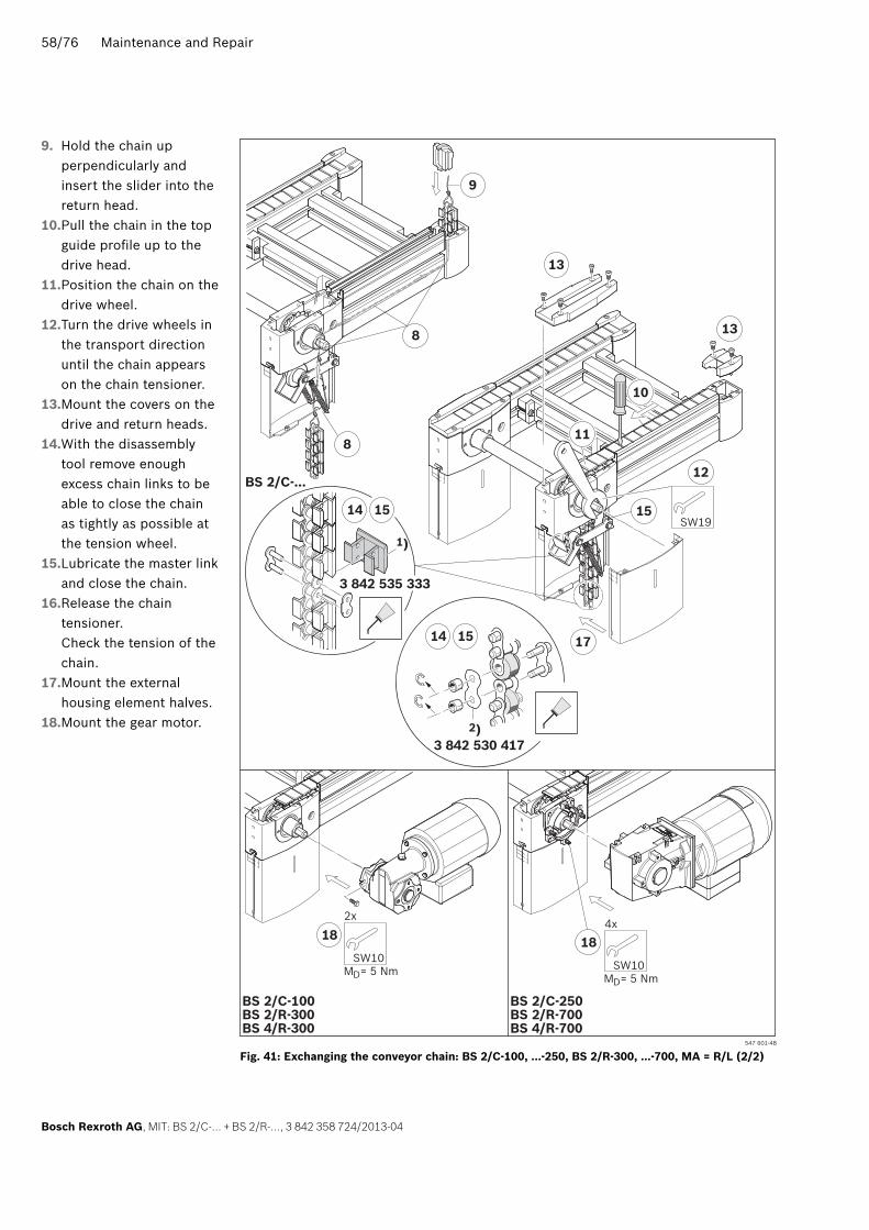
58/76 Maintenance and Repair
Bosch Rexroth AG, MIT: BS 2/C-… + BS 2/R-…, 3 842 358 724/2013-04
Fig. 41:
SW10
18 18
SW10 M = 5 NmD
BS 4/R-700BS 4/R-300BS 2/R-700BS 2/R-300BS 2/C-250BS 2/C-100
BS 2/C-...
M = 5 NmD
4x2x
1)
14 15
14 15
3 842 535 333
8
9
13
13
10
15
17
8
SW19
12
11
547 601-48
2)3 842 530 417
Exchanging the conveyor chain: BS 2/C-100, …-250, BS 2/R-300, …-700, MA = R/L (2/2)
9. Hold the chain up perpendicularly and insert the slider into the return head.
10. Pull the chain in the top guide profi le up to the drive head.
11. Position the chain on the drive wheel.
12. Turn the drive wheels in the transport direction until the chain appears on the chain tensioner.
13. Mount the covers on the drive and return heads.
14. With the disassembly tool remove enough excess chain links to be able to close the chain as tightly as possible at the tension wheel.
15. Lubricate the master link and close the chain.
16. Release the chain tensioner. Check the tension of the chain.
17. Mount the external housing element halves.
18. Mount the gear motor.
358724_2013_04_EN.indd 58358724_2013_04_EN.indd 58 27.05.2013 13:08:1127.05.2013 13:08:11

Maintenance and Repair 59/76
3 842 358 724/2013-04, MIT: BS 2/C-… + BS 2/R-…, Bosch Rexroth AG
10.4.17 Exchanging the conveyor chain:BS 2/C-100, BS 2/R-300, BS 4/R-300 motor mounting (MA) = M
Fig. 42: 547 601-49
8 981 010 511
1
2
8
3
3
1
2
8 981 010 510
9
4
7
4
6
5
Exchanging the conveyor chain BS 2/C-100, BS 2/R-300, MA = M (1/3)
Note:Perform the work steps on both sides at the same time.
Dismount the chain:1. Disassemble the external
housing element halves.2. Secure the chain
tensioner.
3. Open the chain with the disassembly tool3).
3) Disassembly tool: – For the fl at top chain: 3 842 010 510 – For the accumulation roller chain: 3 842 010 511
4. Disassemble the covers on the drive and return heads.
5. Pull the chain back until the drive head is exposed.
6. Remove the slider.7. Dismount the drive train.8. Pull the used chain
downwards from the BS 2….
9. Remove the slider from the return head.
EN
GLI
SH
358724_2013_04_EN.indd 59358724_2013_04_EN.indd 59 27.05.2013 13:08:1227.05.2013 13:08:12

60/76 Maintenance and Repair
Bosch Rexroth AG, MIT: BS 2/C-… + BS 2/R-…, 3 842 358 724/2013-04
Fig. 43: 547 601-50
10
11
10
Exchanging the conveyor aid: BS 2/C-100, BS 2/R-300, MA = M (2/3)
Mount the chain:10. Pull the new chain5) up
to the return head with a pulling aid.
5) BS 2/C…, BS 2/R…: Note the direction of movement of the chain Fig. 38, page 56.
11. Hold the chain up perpendicularly and insert the slider into the return head.
Note:For the next assembly step you will need a helper or a lift aid.
358724_2013_04_EN.indd 60358724_2013_04_EN.indd 60 27.05.2013 13:08:1227.05.2013 13:08:12

Maintenance and Repair 61/76
3 842 358 724/2013-04, MIT: BS 2/C-… + BS 2/R-…, Bosch Rexroth AG
Fig. 44:
3 842 530 417
1918
1918
21
20
21
17
14
13
15
17
12
16
2)
547 601-51
8 981 010 511
8 981 010 510
3 842 530 417
Exchanging the conveyor chain: BS 2/C-100, BS 2/R-300, MA = M (3/3)
12. Pull the chain in the top guide profi le up to the drive head.
13. Hold the drive train over the drive heads.
14. Lead the chain over the drive wheels through the drive head downwards to the chain tensioner.
15. Insert the drive train into the drive heads.
16. Lift the chain up slightly and place the slider into the drive heads.
17. Mount the covers on the drive and return head
18. With the disassembly tool remove enough excess chain links to be able to close the chain as tightly as possible at the tension wheel.
19. Lubricate the master link and close the chain.
20. Release the chain tensioner. Check the tension of the chain.
21. Mount the external housing element halves.
EN
GLI
SH
358724_2013_04_EN.indd 61358724_2013_04_EN.indd 61 27.05.2013 13:08:1327.05.2013 13:08:13

62/76 Maintenance and Repair
Bosch Rexroth AG, MIT: BS 2/C-… + BS 2/R-…, 3 842 358 724/2013-04
10.4.18 Exchanging the conveyor chain: BS 2/C-H, BS 2/R-H, BS 2/R-V-1200, motor mounting (MA) = R/L
Fig. 45: 547 601-52
4 4 4
M
4x
D= 7 NmSW4
SW10MD = 8 Nm
9
3X
"X"
M
4x
D= 7 NmSW4
2
1
7
6
5
BS 2/R-H BS 2/R-VBS 2/C-H
2
6
8 981 010 510 3 842 539 3578 981 010 511
Exchanging the conveyor chain: BS 2/C-H, BS 2/R-H, BS 2/R-V-1200, MA = R/L (1/3)
Note:Perform the work steps on both sides at the same time.
Dismount the chain:1. Dismount the gear
motor.2. Disassemble the side
cover plates, remove the bottom cover sheets.
3. Secure the chain tensioner.
4. Open the chain with the disassembly tool3).
3) Disassembly tool: – For the fl at top chain: 3 842 010 510 – For the accumulation roller chain: 3 842 010 511 – For Vplus accumulation roller chain: 3 842 539 357
5. Dismount the cover of the return head.
6. Pull the used chain downwards from the BS 2….
7. Remove the slider from the return head.
8. Remove the return wheels from the return head.
358724_2013_04_EN.indd 62358724_2013_04_EN.indd 62 27.05.2013 13:08:1327.05.2013 13:08:13

Maintenance and Repair 63/76
3 842 358 724/2013-04, MIT: BS 2/C-… + BS 2/R-…, Bosch Rexroth AG
Fig. 46: 547 601-53
M
4x
D= 7 NmSW4
X
Y
Y
9
9
9
10
11
11
10
10
Exchanging the conveyor chain: BS 2/C-H, BS 2/R-H, BS 2/R-V-1200, MA = R/L (2/3)
Mounting the chain:9. Pull the new chain5) up
to the return head with a pulling aid.
5) BS 2/C…, BS 2/R…: Note the direction of movement of the chain Fig. 38, page 56.
10. Lay the chain around the return wheel in the return head.
11. Mount the slider into the return head.
EN
GLI
SH
358724_2013_04_EN.indd 63358724_2013_04_EN.indd 63 27.05.2013 13:08:1427.05.2013 13:08:14

64/76 Maintenance and Repair
Bosch Rexroth AG, MIT: BS 2/C-… + BS 2/R-…, 3 842 358 724/2013-04
Fig. 47:
SW10MD = 8 Nm
16
X
18
M
4x
D= 7NmSW4
18
12
12
14
19
M
4x
D= 7NmSW4
SW27
15 16
15 163 842 535 333
BS 2/R-H BS 2/R-VBS 2/C-H
3 842 530 417
3 842 538 87215 16
547 601-54
13
Exchanging the conveyor chain: BS 2/C-H, BS 2/R-H, BS 2/R-V-1200, MA = R/L (3/3)
12. Pull the chain in the top guide profi le up to the drive head.
13. Position the chain on the drive wheel.
14. Turn the drive wheels in the transport direction until the chain appears on the chain tensioner.
15. With the disassembly tool remove enough excess chain links to be able to close the chain as tightly as possible at the chain tensioner.
16. Lubricate the master link and close the chain.
17. Release the chain tensioner. Check the tension of the chain.
18. Mount the bottom cover sheets and the side cover plates.
19. Mount the gear motor.
358724_2013_04_EN.indd 64358724_2013_04_EN.indd 64 27.05.2013 13:08:1527.05.2013 13:08:15

Maintenance and Repair 65/76
3 842 358 724/2013-04, MIT: BS 2/C-… + BS 2/R-…, Bosch Rexroth AG
10.4.19 Exchanging the conveyor chain: BS 2/R-H, reversible, BS 2/R-V, reversible, motor mounting (MA) = R/L
Fig. 48: 547 601-56
6
8
4
7 BS 2/R-H
BS 2/R-V 3 842 539 537
8 981 010 511
3
5
5
1
4XSW10MD= 8 Nm
2
4
M
4x
D= 7 NmSW4
Exchanging the conveyor chain: BS 2/R-H, reversible, BS 2/R-V, reversible (1/2)
Note:Perform the work steps on both sides at the same time.
Dismount the chain:1. Dismount the gear
motor.2. Disassemble the side
cover plates, remove the bottom cover sheets.
3. Disassemble the external housing element halves.
4. Secure the chain tensioners to the drive and the return unit.
5. Open the chain with the disassembly tool3) on the return unit.
3) Disassembly tool: – For the accumulation roller chain: 3 842 010 511 – For Vplus accumulation roller chain: 3 842 539 357
6. Dismount the cover of the return head.
7. Pull the used chain downwards from the BS 2….
8. Remove the slider from the return head.
EN
GLI
SH
358724_2013_04_EN.indd 65358724_2013_04_EN.indd 65 27.05.2013 13:08:1627.05.2013 13:08:16

66/76 Maintenance and Repair
Bosch Rexroth AG, MIT: BS 2/C-… + BS 2/R-…, 3 842 358 724/2013-04
Fig. 49: 547 601-57
121111 12
BS 2/R-H BS 2/R-V
3 842 530 417
3 842 538 872
17
14
13
14
15
10
189
9
9
M
4x
D= 7 NmSW4
16
SW10MD=8 Nm
13
X
3 842 539 3578 981 010 511
Exchanging the conveyor chain: BS 2/R-H, reversible, BS 2/R-V, reversible (2/2)
Mount the chain:9. Pull the new chain6) up
to the return head with a pulling aid.
5) BS 2/C…, BS 2/R…: Note the direction of movement of the chain Fig. 38, page 56.
10. Lay the chain around the chain tensioner and the drive wheel and pull it in the top guide profi le up to the return head.
11. With the disassembly tool remove enough chain links to be able to close the chain as tightly as possible at the tension wheel.
12. Lubricate the master link and close the chain.
13. Release the chain tensioner.Check the tension of the chain.
14. Mount the external housing element halves.
15. Mount the bottom cover sheets and the side cover plates.
16. Mount the gear motor.
358724_2013_04_EN.indd 66358724_2013_04_EN.indd 66 27.05.2013 13:08:1727.05.2013 13:08:17
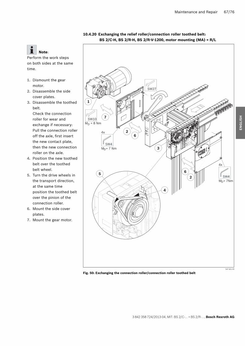
Maintenance and Repair 67/76
3 842 358 724/2013-04, MIT: BS 2/C-… + BS 2/R-…, Bosch Rexroth AG
10.4.20 Exchanging the relief roller/connection roller toothed belt: BS 2/C-H, BS 2/R-H, BS 2/R-V-1200, motor mounting (MA) = R/L
Fig. 50: 547 601-55
M
4x
D= 7 NmSW4
SW27
SW10MD = 8 Nm
7
26
1
3
62
4
5
M
4x
D= 7NmSW4
Exchanging the connection roller/connection roller toothed belt
Note:Perform the work steps on both sides at the same time.
1. Dismount the gear motor.
2. Disassemble the side cover plates.
3. Disassemble the toothed belt.Check the connection roller for wear and exchange if necessary:Pull the connection roller off the axle, fi rst insert the new contact plate, then the new connection roller on the axle.
4. Position the new toothed belt over the toothed belt wheel.
5. Turn the drive wheels in the transport direction, at the same time position the toothed belt over the pinion of the connection roller.
6. Mount the side cover plates.
7. Mount the gear motor.
EN
GLI
SH
358724_2013_04_EN.indd 67358724_2013_04_EN.indd 67 27.05.2013 13:08:1727.05.2013 13:08:17

68/76 Maintenance and Repair
Bosch Rexroth AG, MIT: BS 2/C-… + BS 2/R-…, 3 842 358 724/2013-04
10.4.21 Exchanging the motor and/or gear:BS 2/C-100, BS 2/R-300, BS 4/R-300, motor mounting (MA) = R/L
Fig. 51: 547 601-60
4
SW8MD = 5 Nm
(4x)
X
Antiseize3
5
gleitmo 585K
2
1
SW8MD = 5 Nm
(2x)
Exchanging the motor and/or gear, motor mounting (MA) = R/L
Note: • The plane surfaces on the motor and gear must be undamaged. • The hub of the gear has already been greased with ‘Anti-Seize’ at the factory. • Do not tilt the motor, make sure there is enough clearance for assembling the motor.
• Position the motor correctly (terminal box!) and mount the motor in the gear. If the motor is not properly positioned: do NOT turn it. Disconnect the motor from the gear and assemble it again.
If only the motor is to be exchanged, begin with step 4.
1. Loosen the hexagonal screws on the fl ange.
2. Remove the motor gear combination from the hexagonal shaft.
3. Remove the cover plugs from the faulty gear and fi t onto the new gear.
4. Loosen the hexagonal screws on the gear fl ange.
5. Disconnect the faulty gear from the motor.
6. Remove the yellow protective cap (X) from the shaft on the new motor.Grease the motor shaft.
7. Mount the motor.8. Assemble the motor/gear
combination.
358724_2013_04_EN.indd 68358724_2013_04_EN.indd 68 27.05.2013 13:08:1827.05.2013 13:08:18

Maintenance and Repair 69/76
3 842 358 724/2013-04, MIT: BS 2/C-… + BS 2/R-…, Bosch Rexroth AG
10.4.22 Exchanging the motor and/or gear:BS 2/C-100, BS 2/R-300, BS 4/R-300, motor mounting (MA) = M
Fig. 52: 547 601-64
3
SW8MD = 5 Nm
(4x)
X
4
1
SW8MD = 5 Nm
(2x)
gleitmo 585K
2
Antiseize
Exchanging the motor and/or gear, motor mounting (MA) = M
Note: • The plane surfaces on the motor and gear must be undamaged. • The hub of the gear has already been greased with ‘Anti-Seize’ at the factory. • Do not tilt the motor, make sure there is enough clearance for assembling the motor.
• Position the motor correctly (terminal box!) and mount the motor in the gear. If the motor is not properly positioned: do NOT turn it. Disconnect the motor from the gear and assemble it again.
For dismounting the drive train see Exchanging the conveyor chain, page 59, step 1 to step 7.The drive train does not have to be dismounted if only the motor has to be replaced.In that case begin with step 4.
1. Loosen the hexagonal screws on the fl ange.
2. Disconnect the motor/gear combination from the drive train.
3. Loosen the hexagonal screws on the gear fl ange.
4. Disconnect the faulty gear from the motor.
5. Remove the yellow protective cap (X) from the shaft on the new motor.Grease the motor shaft.
6. Assemble the motor.7. Assemble the drive train.
For assembling the drive train see Exchanging the conveyor chain, page 61, step 12 to step 21.
EN
GLI
SH
358724_2013_04_EN.indd 69358724_2013_04_EN.indd 69 27.05.2013 13:08:1827.05.2013 13:08:18
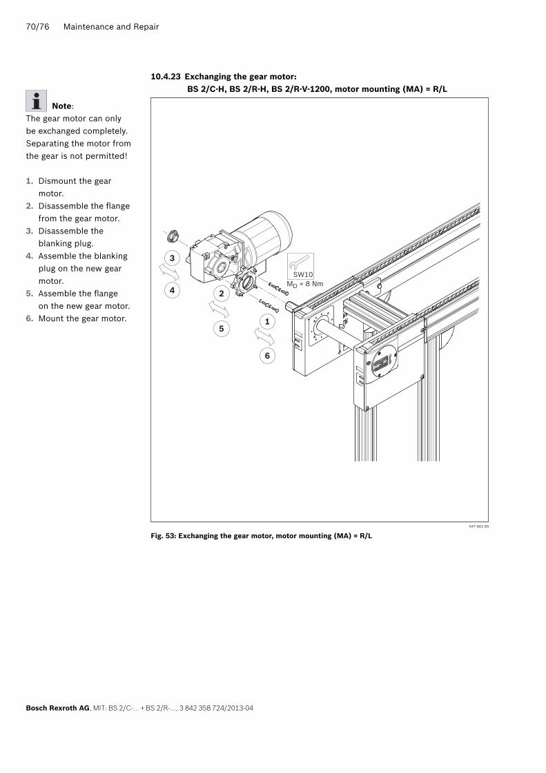
70/76 Maintenance and Repair
Bosch Rexroth AG, MIT: BS 2/C-… + BS 2/R-…, 3 842 358 724/2013-04
10.4.23 Exchanging the gear motor:BS 2/C-H, BS 2/R-H, BS 2/R-V-1200, motor mounting (MA) = R/L
Fig. 53: 547 601-65
SW10MD = 8 Nm
3
4 2
51
6
Exchanging the gear motor, motor mounting (MA) = R/L
Note:The gear motor can only be exchanged completely. Separating the motor from the gear is not permitted!
1. Dismount the gear motor.
2. Disassemble the fl ange from the gear motor.
3. Disassemble the blanking plug.
4. Assemble the blanking plug on the new gear motor.
5. Assemble the fl ange on the new gear motor.
6. Mount the gear motor.
358724_2013_04_EN.indd 70358724_2013_04_EN.indd 70 27.05.2013 13:08:1927.05.2013 13:08:19

Maintenance and Repair 71/76
3 842 358 724/2013-04, MIT: BS 2/C-… + BS 2/R-…, Bosch Rexroth AG
10.4.24 Exchanging the gear motor:BS 2/C-H, BS 2/R-H, BS 2/R-V-1200, motor mounting (MA) = M
Fig. 54: 547 601-66
SW10MD = 8 Nm
4 5 6 8
6
3
8
7
M
4x
D= 7 NmSW4
M
4x
D= 7 NmSW4
2
2
1
Exchanging the gear motor, motor mounting (MA) = M
Note:The gear motor can only be exchanged completely. Separating the motor from the gear is not permitted!
1. Disassemble the side cover plates.
2. Remove the retainer rings from the hexagonal shaft.
3. Push the hexagonal shaft out of the drive.Keep the sheath tube for reusing.
4. Disassemble the fl ange from the gear motor.
5. Assemble the fl ange on the new gear motor.
6. Assemble the gear motor and tighten the screws by hand.
7. Push the hexagonal shaft into the drive.Attach the sheath tube. Secure the hexagonal shaft with retainer rings.
8. Once the gear motor is centered through the hexagonal shaft, tighten the screws fi rmly.
EN
GLI
SH
358724_2013_04_EN.indd 71358724_2013_04_EN.indd 71 27.05.2013 13:08:1927.05.2013 13:08:19

72/76 Maintenance and Repair
Bosch Rexroth AG, MIT: BS 2/C-… + BS 2/R-…, 3 842 358 724/2013-04
10.4.25 Exchanging the glide profi les: BS 2/C-100, BS 2/C-250, BS 2/C-H
Fig. 55: 547 601-67
6,8
M4
99
BS 2/C-HBS 2/C-250
BS 2/C-100
MD = 25 NmT 40
2 7
3
5
Exchanging glide profi les: BS 2/C-100, BS 2/C-250, BS 2/C-H
1. Dismount the chain, see pages 57/59/62.
2. Dismount the return head.
3. Disassemble the locking bolts.
4. Exchange the glide profi les.
5. Fix the glide profi les and drill them open.
6. Assemble the locking bolts.
7. Mount the return head.8. Mount the chain, see
pages 58/61/64.
358724_2013_04_EN.indd 72358724_2013_04_EN.indd 72 27.05.2013 13:08:2027.05.2013 13:08:20
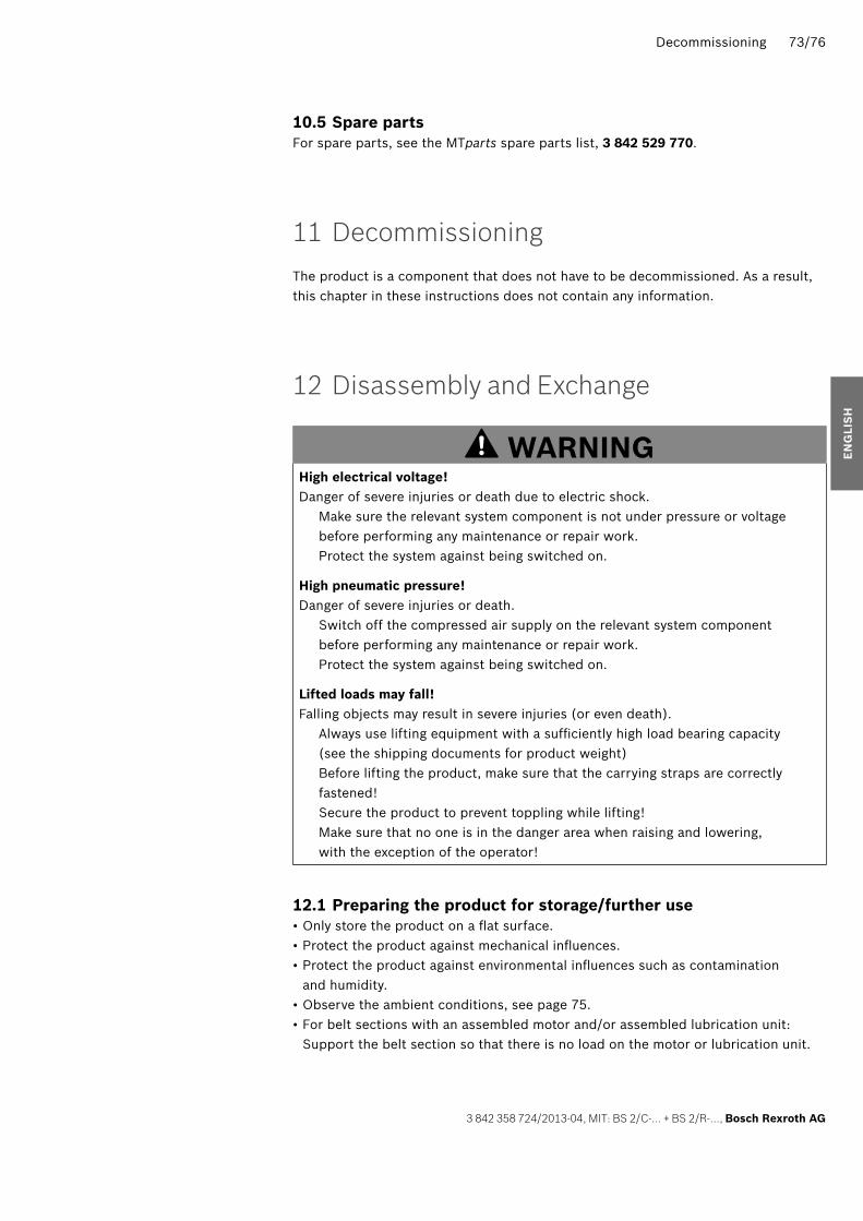
Decommissioning 73/76
3 842 358 724/2013-04, MIT: BS 2/C-… + BS 2/R-…, Bosch Rexroth AG
10.5 Spare partsFor spare parts, see the MTparts spare parts list, 3 842 529 770.
11 Decommissioning
The product is a component that does not have to be decommissioned. As a result, this chapter in these instructions does not contain any information.
12 Disassembly and Exchange
WARNINGHigh electrical voltage!Danger of severe injuries or death due to electric shock. Make sure the relevant system component is not under pressure or voltage
before performing any maintenance or repair work. Protect the system against being switched on.
High pneumatic pressure!Danger of severe injuries or death. Switch off the compressed air supply on the relevant system component
before performing any maintenance or repair work. Protect the system against being switched on.
Lifted loads may fall! Falling objects may result in severe injuries (or even death). Always use lifting equipment with a suffi ciently high load bearing capacity
(see the shipping documents for product weight) Before lifting the product, make sure that the carrying straps are correctly
fastened! Secure the product to prevent toppling while lifting! Make sure that no one is in the danger area when raising and lowering,
with the exception of the operator!
12.1 Preparing the product for storage/further use • Only store the product on a fl at surface. • Protect the product against mechanical infl uences. • Protect the product against environmental infl uences such as contamination and humidity.
• Observe the ambient conditions, see page 75. • For belt sections with an assembled motor and/or assembled lubrication unit: Support the belt section so that there is no load on the motor or lubrication unit.
EN
GLI
SH
358724_2013_04_EN.indd 73358724_2013_04_EN.indd 73 27.05.2013 13:08:2027.05.2013 13:08:20

74/76 Disposal
Bosch Rexroth AG, MIT: BS 2/C-… + BS 2/R-…, 3 842 358 724/2013-04
13 Disposal
• The materials used are environmentally sustainable. • They may be recycled or reused (if components are converted or replaced). Recyclability is ensured by the selection of material and the possibility to take the components apart.
• Careless disposal of the product may pollute the environment. • Dispose of the product in accordance with the currently applicable national regulations in your country.
14 Extension and Conversion
• Do not convert the product. • The Bosch Rexroth warranty only applies to the delivered confi guration and extensions taken into account in the confi guration. The manufacturer can accept no warranty claims if the system is converted or extended in a manner not listed in these instructions.
15 Troubleshooting and Resolution
• If you are unable to remedy the error, please get in touch with one of the contact addresses listed at www.boschrexroth.com.
358724_2013_04_EN.indd 74358724_2013_04_EN.indd 74 27.05.2013 13:08:2027.05.2013 13:08:20

Technical Data 75/76
3 842 358 724/2013-04, MIT: BS 2/C-… + BS 2/R-…, Bosch Rexroth AG
16 Technical Data
• For dimensions, see the sales catalog TS 2plus, 3 842 531 138. • Maximum load/section load:
– BS 2/C-100 belt section: max. 100 kg / 1.0 kg/cm of support surface length – BS 2/C-250 belt section: max. 250 kg / 1.0 kg/cm of support surface length – BS 2/C-H belt section: max. 400 kg / 2.0 kg/cm of support surface length – BS 2/R-300 belt section: max. 300 kg / 1.5 kg/cm of support surface length – BS 4/R-300 belt section: max. 300 kg / 1.5 kg/cm of support surface length – BS 2/R-700 belt section: max. 700 kg / 1.5 kg/cm of support surface length – BS 4/R-700 belt section: max. 700 kg / 1.5 kg/cm of support surface length – BS 2/R-H belt section: max. 1200 kg / 2.0 kg/cm of support surface length – BS 2/R-V-1200 belt section: max. 1200 kg / 1.5 kg/cm of support surface length
• Noise emissions: < 70 dB (A)
16.1 Ambient conditions • The transfer systems have been designed for stationary use in a location that is protected from the elements.
• Operating temperature
+5°C to +40°C–5°C to +60°C with 20% reduced load
• Storage temperature –25°C to +70°C
• Relative humidity 5% to 85%
• Air pressure > 84 kPa, appropriate height < 1400 m above sea level
• Permissible fl oor load: 1000 kg/m2
• The load values of the electrical drives are reduced by 15% when the system is set up in a location with an altitude > 1400 m.
• Avoid molds, fungi, rodents, and other vermin. • Do not install or operate near industrial systems with chemical emissions. • Do not install or operate near sandy or dusty sources. • Do not install or operate in areas that are regularly jarred by high forces caused by e.g. presses or heavy machinery.
• Resistant to many common media used in production such as water, mineral oil, grease, and detergents. Contact your Rexroth representative if you have any doubts about resistance to specifi c chemicals, such as test oil, doped oils, aggressive detergents, solvents, or brake fl uid.
• Avoid long-term contact with acidic or basic reacting materials.E
NG
LIS
H
358724_2013_04_EN.indd 75358724_2013_04_EN.indd 75 27.05.2013 13:08:2027.05.2013 13:08:20

Bosch Rexroth AGPostfach 30 02 07D-70442 StuttgartGermanyFax +49 711 811–[email protected]
Subject to changes.3 842 358 724/2013-04
358724_2013_04_EN.indd 76358724_2013_04_EN.indd 76 27.05.2013 13:08:2027.05.2013 13:08:20