Embed Size (px)
Citation preview
CONCURRENT DETECTION OF TRANSIENT FAULTS IN MICROPROCESSORS
bv
Mohammad Ziaullah Khan
Dissertation submitted to the Faculty of the
Virginia Polytechnic Institute and State University
in partial fulfillment of the requirements for the degree of
DOCTOR OF PHILOSOPHY
in
Electrical Engineering
APPROVED:
May 1989
Blacksburg, Virginia
CONCURRENT DETECTION OF TRANSIENT FAULTS IN MICROPROCESSORS
bv
Mohammad Ziaullah Khan
Dr. Joseph G. Tront (Chairman)
· Electrical EngineeringQ
(ABSTRACT)
A large number of errors in digital systems are due to the presence of transient faults.
This is especially true of microprocessor-based systems working in a radiation envi-
ronment that experience transient faults due to single event upsets. These upsets
cause a temporary change in the state of the system without any permanent damage.
Because of their random and non-recurring nature, transient faults are difficult to de-
tect and isolate, hence they become a source of major concern, especially in critical
real-time application areas. Concurrent detection of these errors is necessary for
real-time operation.
Most existing fault tolerance schemes either use redundancy to mask effects of tran-
sient faults or monitor the system for abnormal operations and then perform recovery
operation. Although very effective, redundancy schemes incur substantial overhead
that makes them unsuitable for small systems. Most monitoring schemes, on the
other hand, only detect control flow errors.
A new approach called Concurrent Processor Monitoring for on-line detection of
transient faults is proposed that attempts to achieve high error coverage with small
error detection latency. The concept of the execution profile of an instruction is de-
fined and is used for detecting control flow and execution errors. To implement this

scheme, a watchdog processor is designed for monitoring operation of the main
processor. The effectiveness of this technique is demonstrated through computer
simulations.

Dedication
lv

Acknowledgements
l am deeply indebted to Dr. Joe Tront, my advisor, for his help, guidance, and pa-
tience throughout this endeavor. I sincerely thank Dr. Jim Armstrong for introducing
me to digital system modeling and simulation. My thanks also to Drs. Dong Ha,
Charles Nunnally and Ezra Brown for serving on my committee. l also wish to thank
Bob Lineberry for the endless hours he spent to get the new computer running for
this work. This work was initially supported in part by Naval Research Laboratories
under contract number FE238311.
l am grateful to my brothers and sisters who through their letters and phone calls
have provided the emotional support. And last, but not least, l wish to express my
gratitude to my parents for their love and affection. Their faith in my abilities has al-
ways been a great source of inspiration for me.
Acknowledgements v
Table of Contents
Introduction ............................................................ 1
1.1 Faults in Digital Systems .............................................. 2
1.2 Single Event Upset Phenomenon ........................................ 3
1.3 SEU Induced Errors .................................................. 4
1.3.1 Data Errors ..................................................... 5
1.3.2T
Control Flow Errors ............................................... 5
1.3.3 Execution Errors ................................................. 6
1.4 Fault Tolerance Concepts ............................................. 6
1.4.1 Self Diagnosis ................................................... 7
1.4.2 Redundancy ..................................................... 7
1.4.3 System Monitoring ................................................ 8
1.5 Purpose and Signiticance of this Research ................................ 9
1.6 Organization of the Dissertation ........................................ 10
Previous Research ...................................................... 12
2.1 Fault Tolerance Techniques ........................................... 13
2.1.1 Technology Approach ............................................ 13
2.1.2 Statistical Approach .............................................. 14
Table or Contents vl
2.1.3 Hardware Approach .............................................. 15
2.1.4 Software Approach .............................................. 16
2.1.5 Hybrid Approach ................................................ 17
2.1.6 Circuit Design Approach .......................................... 20
2.2 Limitations of Previous Techniques ..................................... 21
Concurrent Processor Monitoring Scheme .................................... 24
3.1 Fault Observation ................................................... 24
3.2 Concurrent Processor Monitoring ...................................... 26
3.3 Assumptions ...................................................... 28
3.4 Transient Fault Model ...........................................,... 29
3.5 Instruction Execution Profile ........................................... 31
3.6 Detectable Errors ................................................... 32
3.7 Detection Mechanisms ............................................... 37
Design Implementation .................................................. 40
4.1 Design Requirements ................................................ 40
4.2 8086 Basics ................................................,...... 42
4.3 Execution Profile Verification .......................................... 43
4.3.1 The Execution Profile Verification Algorithm ............................ 44
4.3.2 Discussion ..................................................... 45
4.4 Address Verification ................................................. 45
4.4.1 The Next Address Verification Algorithm .............................. 45
4.4.2 Discussion ..................................................... 46
4.5 Additional Detection Mechanisms ...................................... 47
4.6 Watchdog Processor Architecture for the 8086 ............................. 49
4.6.1 Execution Time Check (ETC) ....................................... 50
4.6.2 Byte Count Check (BCC) .......................................... 52
Table of Contents vii
4.6.3 Data Transfer Check (DTC) ........................................ 52
4.6.4 Data Size Check (DSC) ........................................... 56
4.6.5 Next Address Check (NAC) ........................................ 56
4.6.6 Illegal Opcode Check (IOC) ........................................ 58
4.6.7 Stack Address Check (SAC) ........................................ 60
4.6.8 Undefined Memory Access (UMA) ................................... 63
4.6.9 lmproper Queue Update Signals (IQS) ................................ 63
4.6.10 lmproper Memory Access (IMA) .................................... 65
Concept Verification .................................................... 68
5.1 The Need for Simulation ............................................. 68
5.2 Level of Simulation ................................................. 69
5.3 Simulation Environment .............................................. 70
5.4 Experimental Configuration ........................................... 71
5.4.1 Prototype Test System ............................................ 71
5.4.2 Testbed Setup .................................................. 72
5.4.3 Test Program ................................................... 74
5.4.4 Injected Fault Types .............................................. 76
Performance Evaluation .................................................. 79
6.1 Assessment Parameters ............................................. 79
6.2 Analytical Results .................................................. 81
6.2.1 Error Coverage ................................................. 82
6.2.2 Error Detection Latency ........................................... 86
6.3 Experimental Results ................................................ 87
6.3.1 Distribution of Injected Faults ....................................... 87
6.3.2 Error Coverage ................................................. 92
6.3.3 Error Detection Latency ........................................... 94
Table of Contents vlll
6.4 Hardware Overhead of the CPM Scheme ................................. 97
6.5 Reliability ........................................................ 102
Analysis ol Results .................................................... 105
7.1 Error Coverage ................................................... 105
7.2 Error Detection Latency ............................................. 111
Concluslons .......................................................... 115
8.1 Comparison of CPM With Other Schemes ............................... 116
8.2 Future Directions .................................................. 118
Bibliography ......................................................... 121
Simulation Model of the WDP ............................................. 128
Prototype System Conllguratlon ........................................... 148
Test Program Llstlng ................................................... 150
Fault-free Simulation Run ............................................... 152
Fault Simulation Run ................................................... 179
Vita ................................................................ 191
Table of Contents ix
List of lllustrations
Figure 1. Watchdog Processor Interface ..............................41
Figure 2. Architecture of the Watchdog Processor ......................51
Figure 3. Execution Time Check ....................................53
Figure 4. Byte Count Check .......................................54
Figure 5. Data Transfer Check .....................................55
Figure 6. Data Size Check .........................................57
Figure 7. Next Address Check .....................................59
Figure 8. Illegal Opcode Check .....................................61
Figure 9. Stack Address Check .....................................62
Figure 10. Undefined Memory Access Check ...........................64
Figure 11. Improper Queue Update Signals Check .......................66
Figure 12. Improper Memory Access Check ............................67
Figure 13. The Prototype Test System ................................73
Figure 14. The Simulation Environment ...............................75
Figure 15. Simulation Results .......................................88
Figure 16. Distribution of Injected Faults ...............................90
Figure 17. Distribution of Errors .....................................91
Figure 18. Performance of Individual Mechanisms .......................95
Figure 19. Error Latency of Individual Mechanisms (In clock cycles) ..........98
Figure 20. Error Latency of Individual Mechanisms (in Instruction cycles) .....99
List er lllustrations x
Figure 21. lmprovement in System Reliability ..........................104
Figure 22. Multiple Detections of a Fault (in clock cycles) .................107
Figure 23. Multiple Detections of a Fault (in instruction cycles) ............108
Figure 24. Performance Efficiency of WDP ............................113
List ol lllustrationsE
xl
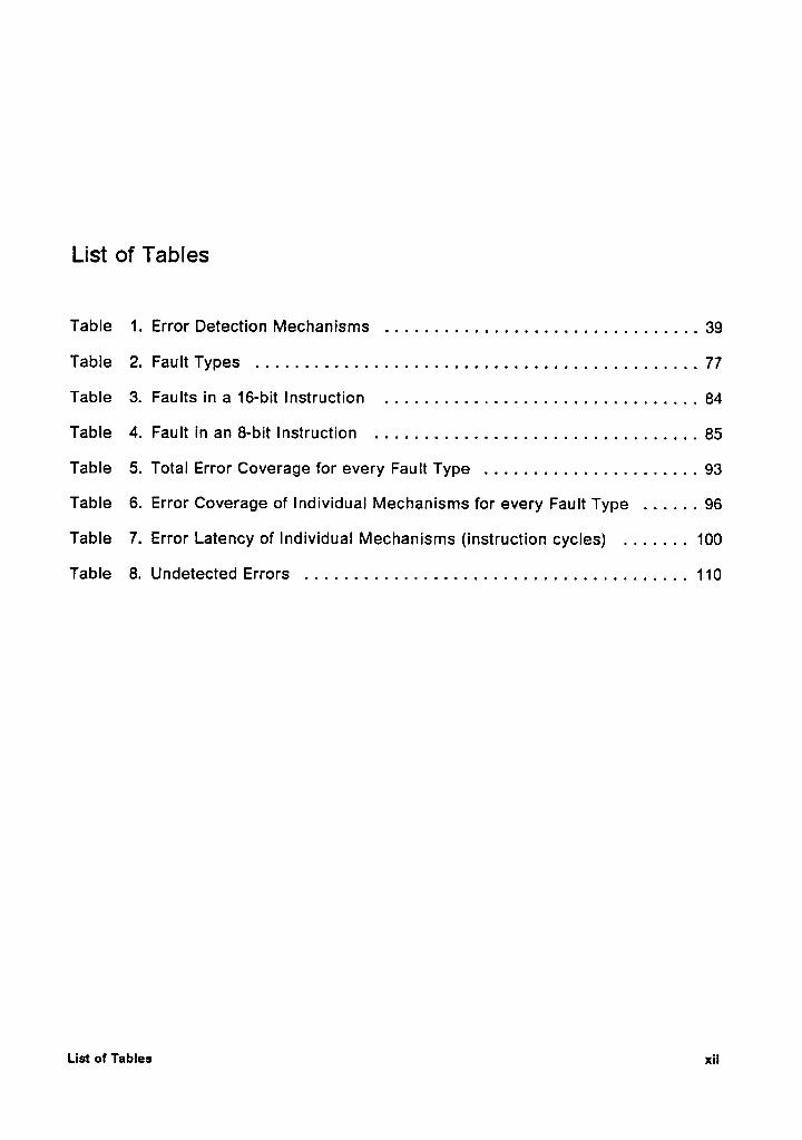
List of Tables
Table 1. Error Detection Mechanisms ................................39
Table 2. Fault Types .............................................77
Table 3. Faults in a 16-bit Instruction ................................84
Table 4. Fault in an 8-bit Instruction .................................85
Table 5. Total Error Coverage for every Fault Type ......................93
Table 6. Error Coverage of Individual Mechanisms for every Fault Type ......96
Table 7. Error Latency of Individual Mechanisms (instruction cycles) .......100
Table 8. Undetected Errors .......................................110
List or Tables xn
Chapter 1
Introduction
The cost and flexibility of microprocessors has made them very attractive for use in
control applications. These include real-time control systems where very high reli-
ability and availability is required because these systems cannot stop to recover from
an error. In addition to high reliability, these systems should also have self repair
capability. This is especially true for systems that are used for the guidance and
control of satellites. These spacecrafts, once launched, remain unattended for their
entire life span and, therefore, must continue to perform satisfactorily in the presence
of faults [1-3]. Several systems have been developed which satisfy these require-
ments by using redundancy schemes [2,4-7]. Since small satellite controllers have
very limited power and weight budgets, the use of redundancy techniques is not a
desirable option.
The constraints involved in achieving fault tolerance in digital systems are explored
in this chapter. The types of faults that may occur in a digital system are enumerated
with emphasis on transient faults. A discussion of some general techniques for fault
~Introduction 1

tolerant design and their Iimitations in detecting transient fauits is presented. An
outiine of the organization of this dissertation concludes this chapter.
1.1 Faults in Digital Systems
Faults in a computer system are classified by extent, value, and duration. Extent in-
dicates whether errors produced by fauits are localized or distributed; value denotes
if fauits generate fixed or varying erroneous data values; duration refers to whether
a fault is permanent or temporary [8]. Permanent fauits can be due to a variety of
reasons including incorrect logic design, manufacturing defects, harsh environmental
abuse, worn out parts, total dose of radiation deposit, and software bugs. Permanent
fauits appear as stuck-at fauits, floating fauits, or parametric fauits and remain in the
system until removed by an explicit action such as repair or replacement [9,10]. Most
of these fauits can be eliminated by taking the necessary precautionsin the design,
manufacturing and testing phases. Environmental abuse can be minimized by pro-
viding proper housing and shielding of components. Temporary fauits are classified
as either intermittent or transient. An intermittent fault manifests itself at regular in-
tervals and is due to partially defective components, loose connections, devices with
small tolerances, or poor design. A marginally working component functions prop-
erly some of the time but not at other times and is a typical example of an intermittent
fault [11]. A transient fault, on the other hand, is a random, non-recurring fault which
is present for a short interval oftime. It may be caused by cosmic radiations, protons,
alpha particles, other high energy nuclei, or glitches in the power supply [11-20].
[11.-20.]. Since a transient fault disappears after the interference is removed and
Introduction 2
leaves no permanent damage to the device, there is no faulty hardware to repair or
replace. That is why transient faults are also referred to as soft faults.
1.2 Single Event Upset Phenomenon
Anomalous behavior in digital circuits of communication satellites has been attributed
to transient faults. This behavior is characterized by changes in the normal operation
of the system without an explicit command such as modification of data stored in the
memory, improper activation of certain control signals, or improper execution of a
sequence of instructions in a program. Research has indicated that space·borne
digital systems are susceptible to transient faults due to the radiation environment in
which they operate [13-20]. A transient fault caused by radiation can produce a
change in the state of a flip flop. This phenomenon is called a single event upset
(SEU). For instance, a change in the state of a flip flop occurs when a charged parti-
cle of sufficient energy is incident on the base emitter junction of a transistor. The
charge on junction capacitance of the sensitive transistor is increased until the
turn-on voltage is reached [13]. The amount of charge needed to turn-on the device
is called the critical charge and is a function of the capacitance of the sensitive node,
the dimensions of the device, and the technology. This phenomenon has been
studied experimentally by bombarding integrated circuits with several types of high
energy particles including protons, alpha particles, carbon (C-12), and iron (Fe-56)
nuclei [21-26]. Typical sources of charged particles include cosmic radiations, other
charged particles in the environment, and the naturally occurring alpha particles in
packaging materials of semiconductor devices. The capacitance of a device node
decreases with decreasing dimensions thus lowering the upset threshold of the de-
lnzmducticn 3
vice [3,13]. Considering the ever decreasing feature sizes in VLSI circuits, transient
faults will remain a problem in digital systems that operate in harsh environments.
SEUs were first discovered in flip flops and, therefore, most of the literature on the
subject relates to the study of storage elements. But SEUs also affect combinational
logic. Typically, a digital system consists of several stages of combinational logic
followed by a storage Iatch. An SEU in combinational logic produces a voltage tran-
sient which propagates through the circuit. For this pulse to produce an error, the
following criteria must be satisfied [27-29]:
1. the pulse must be strong enough to propagate through the circuit,
2. a critical pipe should exist from the affected node to a Iatch,
3. the pulse must have sufficiently high amplitude and width to be able to write the
Iatch, and
4. the arrival of the pulse at the Iatch must coincide with its write-enable strobe.
This implies that there is a small probability that an SEU, occurring in combinational
logic, will be registered in a Iatch. Even if it does get Iatched, it appears as ifthe Iatch _
itself experienced an upset. Thus, most of the errors due to SEUs in combinational
logic can be represented by corresponding errors in latches and, therefore, it is suf-
ficient to consider SEUs in latches only for a complete analysis.
1.3 SEU lnduced Errors
Errors produced by SEU may be broadly classified into three categories: data errors,
control flow errors, and execution errors.
Introduction 4
1.3.1 Data Errors
A data error is produced when an upset occurs in a register or a memory location.
The choice of a data error detection strategy is influenced by the location of the error:
memory, bus or the processor. Error tolerant memory architectures either employ
single error correction codes with periodic memory scrubbing or use redundant
memory units. Data errors on the system bus or in the processor can be detected
by coding redundant data with non-redundant data to form a modified value e.g.,
Hamming codes, residue number system, etc. Error codes for detecting data errors
have been well·studied [11,30,31]. Data errors will not be discussed further.
1.3.2 Control Flow Errors
A change in the state of the system that results in loss of control is called a control
flow error. These can be thought of as errors in the addressing logic of the micro-
processor that alter the normal sequence of instructions. These addressing errors
can result in the following situations:
1. execution of an incorrect sequence of instructions, or
2. a branch to/from an incorrect address.
An incorrect jump results in the loss of control and may put the system in an im-
proper state making it difficult to initiate a successful recovery.
Introduction‘
5
1.3.3 Execution Errors
A perturbation in the internal registers of a microprocessor during execution of an
instruction can produce an execution error. This can result in the following scenar-
los:
1. no activity takes place,
2. a different instruction is executed instead of the one intended,
3. in addition to the current instruction, another instruction ls also executed,
4. an instruction gets aborted during execution l.e., partial instruction execution,
5. an illegal opcode pattern is created, or
6. an improper control signal is generated.
The difficulty in detection of instruction execution errors arises from the fact that the
internal signals and register operations of a microprocessor are not externally ob-
servable.
1.4 Fault Tolerance Concepts
Faults in a digital system can produce errors that can be detrimental to its perform-
ance. There are two strategies to combat these: fault prevention and fault tolerance
[8,11,12,30,31]. Fault prevention schemes attempt to prevent, by construction, the
occurrence of faults. A priori knowledge of all possible failure modes is required in
designing a completely fault free system. Glven the complexity of modern circuits,
this is almost an impossible goal to achieve. Therefore, effort is made to reduce the
Introduction 6
probability of a fault to an acceptably low level. Fault tolerance schemes, on the
other hand, assume that a certain number of faults will occur despite using reliable
components. Consequently an attempt is made to design the system so that it auto-
matically counter acts the effects of faults.
Techniques for incorporating fault tolerance in a computer system can be broadly
classified into three categories: self diagnosis, redundancy, and system monitoring.
An overview of these schemes and their suitability for detection of transient faults
follows.
1.4.1 Self Diagnosis
ln this approach, the processor executes a diagnostic program which tests each of its
functional blocks. This requires a minimal amount of external hardware, such as in-
terrupt logic, that periodically triggers the diagnostics [3,32]. Since the processor is
not available for normal processing when diagnostics are executed, it is not a good
system for real-time applications. Also, since faults are detected only when diag-
nostics are run, this scheme cannot detect transient faults that occur during normal
operation.
1.4.2 Redundancy
Redundancy schemes detect or mask faults by using additional hardware or software.
Fault masking by majority voting is the principle behind many redundancy schemes.
Redundancy can be achieved in hardware, software, or time. Hardware redundancy
calls for voting on the outputs of several identical tightly coupled hardware units
Introduction 7
working concurrently [1,11,30]. A number of fauIt·toIerant general purpose computers
that use hardware redundancy are commercially available. Triple Modular Redun-
dancy (TMR) is a popular method where three identical units are used. Although
hardware redundancy has a very small fault Iatency, there is a high hardware over-
head cost associated with it. Software redundancy is attained by using more than
one algorithm to accomplish a given task; possibly on separate processors. The
outputs of different algorithms are voted in software to obtain the final result
[9,10,33,34]. Time redundancy requires executing the same algorithm on the same
or different processors at different times. The outputs from different runs can then
be voted in software later to obtain a final result.
The voting mechanism in redundancy schemes is the single point of failure and must
be made very reliable. Redundancy techniques are very effective in detecting faults,
especially transient faults, but have a high overhead penalty which makes them un-
suitable for small satellite control systems that have limited power and weight
budget.
1.4.3 System Monitoring
The concept of system monitoring by observing certain attributes of a system has
received oonsiderable attention recently. This strategy calls for adding a moderate
amount of hardware to the processor in order to monitor its data, address and control
lines to detect faults. The monitoring hardware can either be external or internal to
the processor. The external monitor is also called a watchdog processor. An internal
monitor has a higher fault observability than an external monitor because it has ac-
lmmduczlun 6
cess to all internal signals of the processor but cannot be used for existing off—the-
shelf microprocessors.
System monitoring methods can be classified into on-line and off-line schemes. An
on-line monitoring scheme detects errors concurrently in real-time when the system
is operational. The off-line monitoring scheme, on the other hand, collects perform-
ance data during normal processing and analyzes it later to verify correct operation.
An on-line monitoring scheme has a higher error detection Iatency than a hardware
redundancy scheme but has a much lower hardware overhead. It operates in real-
time and is, therefore, effective against transient faults. An off·line scheme, on the
other hand, does not detect faults in real-time and, therefore, is not useful for de-
tecting transient faults [35,36].
1.5 Purpose and Significance of this Research
Transient faults will continue to be a problem in digital systems operating in radiation
environments and the situation may become more aggravated in future designs be-
cause of smaller component dimensions. lt is important that faults are detected as
quickly as possible after their occurrence and an appropriate recovery action is taken
to limit the propagation of errors. A fault detection strategy that tries to minimize the
detection time and has a high error coverage is essential.
Most existing techniques attempt to provide fault tolerance by either using redun-
dancy for fault masking or by monitoring the processor for proper operation. The use
of redundancy, although very effective, may not be suitable for applications that have
constraints on their power and weight budget. Most processor monitoring schemes
Introduction s
have limited scope and can only detect certain types of errors. This limits their error
coverage. For instance, most monitoring techniques using signature analyzers detect
only control flow errors. Execution errors are either not covered at all or are detected
with a very long Iatency. This is an undesirable situation because a small latency is
essential for efficient recovery. Therefore, there is a need to develop methods for
implementing fault tolerance at reasonable costs.
The major thrust of this research is to develop a technique that is capable of detect-
ing, in timely fashion, errors produced by SEUs. To this end, the proposed scheme
is aimed at detecting both control flow and execution errors. The implementation of
this scheme shows that most of the hardware used for detecting execution errors can
also be used to detect control flow errors with very few modlfications.
1.6 Organization of the Dissertation
A brief discussion of the problems associated with SEU phenomenon has been pre-
sented in this chapter. The background of the research reported in this dissertation
is presented in Chapter 2. This includes a review of the existing techniques for de-
tecting transient faults in digital systems and their salient features. Next, the Iimita-
tions of these schemes for SEU environment are discussed. ln chapter 3, a functional
fault model of SEU induced errors is presented. The concept of the execution profile
of an instruction is defined and is shown to be effective in detecting transient faults.
The details of the proposed error detection scheme are presented in Chapter 4. The
strategy for testing and evaluating the performance of this scheme is discussed in
chapters 5 and 6, respectively. The results of the testing are analyzed in Chapter 7.
Introduction 10

In Chapter 8, conclusions are drawn from this research and thoughts on further work
are presented.
Introduction11

Chapter 2
Previous Research
Interest in the design of fauit tolerant computers was initially caused by the error
susceptibility of the components: vacuum tubes and relays. The advent of integrated
circuit technology greatly improved component reliability. It became difficult to justify
the cost of automatic fault recovery mechanisms. The emphasis shifted to the testing
of logic so that faulty hardware may be replaced after a quick fault detection [1]. This
concept is very cost effective but requires external help when faulty hardware is
identified. Also the system has to be shut down in order to perform diagnostic tests.
This is not a viable solution for spacecraft systems where external repair facilities are
generally not available and continuous operation is desired. Therefore, an on-line
testing mechanism is required that works concurrently with the system. The ability
to detect faults with small latency is highly desirable. Because of the very nature of
transient faults, all that is needed is to detect them and initiate a recovery. There is
no faulty hardware to repair or replace as transient faults only disturb the state of the
system and do not leave any permanent damage.
Previous Research 12
2.1 Fault Tolerance Techniques
1The problem of SEUs in digital circuits of spacecraft hardware has been of interest for
a long time. Both theoretical and practical work has been done to better understand
the SEU phenomenon and establish criteria for fault tolerant design. This has led to
several fault tolerance approaches that vary in their design and concept. These in-
clude improvement in the manufacturing process, changes in geometric layout of the
lC components, fine tuning of the system based on statistical models, and error de-
tection schemes that range from pure hardware to pure software approaches. A brief
discussion of these concepts follows.
2.1.1 Technology Approach
There have been several experimental studies to understand the nature of SEUs and
their effects on digital devices. In experimental studies the actual environment in
space has been simulated by bombarding integrated circuits with high energy parti-
cles [19-29]. lt has been observed that certain nodes in a circuit are more susceptible
to SEUs than others [37]. This has led to the creation of radiation hardened (rad hard)
technologies. Rad hard components exhlbit several orders of magnitude improve-
ment in immunity to SEUs. An example of how circuits can be rad hardened can be
seen in memory devices where a transistor memory cell may be made more resistant
to SEUs by increasing the coupling resistance of sensitive nodes. Although these
measures have signlficantly decreased the susceptibility of components to SEUs, the
fact remains that it is not possible to completely eliminate SEUs.
Previous Research 13
Many SEUs are caused by high energy particles passing through a circuit and de-
poslting energy in the form of movement of charge. The energy deposit needed for
an upset to occur is proportional to the capacitance of the node. This capacitance
decreases with decreasing dimensions thus Iowering the upset threshold of the de-
vice [24]. By increasing the capacitance of the device it is possible to reduce the
error rate. This means keeplng gate areas large enough to store the critical charge
and source/drain areas small to minimize the path length of incident particle in silicon
[38]. Although experimental evidence supports this idea, it is but a temporary sol-
ution as the device dimensions will undoubtedly become smaller with advancing
technologies. Additionally, increasing capacitor size both increases power con-
sumption and decreases speed, both of which are undesirable effects.
2.1.2 Statistical Approach
A model for predicting the tolerance of a system to transient errors is described in
[39]. It is based on data collected from four existing systems which experienced
transients due to radioactivity in the packaging material of the integrated circuits. A
statistical model has also been developed for designlng microprocessor-based in-
dustrial controllers which is to operate in an electrically noisy environment [40,41].
An assessment of the probability of recovery following a random jump due to an SEU
is discussed in [42] wherein practical measures have been suggested that can in-
crease the probability of recovery necessitating only minor changes in hardware and
software.
Previous Research 14
2.1.3 Hardware Approach
Redundancy techniques have been successfully employed in many reliable systems.
Redundancy in hardware, software, or time, attempts to eliminate errors by masking
faults [1,10,11,30,31,33]. On-line or concurrent detection of faults in microprocessors
has been proposed in the literature using external detectors, watchdog timers, or
partial hardware redundancy [35,36]. One recovery scheme for transient faults has
been implemented by having the microprocessor generate timing pulses at regular
intervals. In the case of a transient error, the train of pulses is disturbed prompting
the external hardware to trigger a reset signal [43]. A self testing methodology for
periodic testing of a microprocessor is described in [32]. lt is important to note that
periodic testing may not be very effective against SEUs which occur randomly for
short durations and do no permanent damage.
A contalnment set theory has been proposed in [44-46]. lt defines the operation of a
microprocessor system by a containment set which consists of a finite number of
mutually exclusive states covering all possible transfer functions (both valid and in-
valid). A transition matrix is then defined over this set which lists the probabilities
of transition from one state to another following an upset. The fault tolerance of the
system can be calculated using this transition matrix. For practical implementations
of these concepts, an experimental study was conducted to assess the performance
of different error detection mechanisms [47]. A hardware detector based on this
concept for detecting transient faults is described in [48,49].
In another hardware solution, the exact execution of an instruction is verified by
comparing its actual signature with a predetermined signature value [50]. The sig-
Previous Research 15
natures are generated by using the control signals of the processor as inputs to a
parallel linear feedback shift register. This scheme has been implemented for an
8085 microprocessor, The instruction set of the 8085 is mapped in 21 valid signa-
tures. This scheme has been implemented for an 8085 microprocessor, whose entire
instruction set is mapped into 21 valid signatures. Fault masking in this approach is
significantly high because many instructions have identical signatures.
2.1.4 Software Approach
A number of purely software approaches to SEU detection have also been proposed.
One such scheme calls for self testing software which can detect transient errors by
checklng the program flow. The software is partitioned into blocks. A unique tag is
created upon entry to a block and cleared upon exit. Any improper jump into another
block induced by an SEU is detected by checklng the tag [50,51]. An automated
scheme for incorporatlng self testing capability in application software has been im-
plemented in [53]. A translator program scansl an Ada application software and in-
serts the necessary code for implementing the self testing mechanisms in software.
Another scheme incorporates fault tolerance by embedding executable assertions in
the software [54,55]. These assertions test the outcome of an algorithm to see if the
results are reasonable. An error is detected if an assertion is violated. A similar
approach calls for using an alternate algorithm if an error is detected [58]. All of
these schemes detect control flow errors only.
Watchdog timers have also been successfully employed to detect certain types of
errors [57]. A watchdog timer is essentially a count down timer which ls preset by
the executing software before a block of code is entered. This preset value is slightly
Previous Research 16
longer than the actual execution time for a particular block. lf the watchdog timer
counts down to zero before the end of the block is reached, the processor has likely
inadvertently branched incorrectly. This error condition is signalled by the watchdog
timer.
2.1.5 Hybrid Approach
The fault tolerance schemes described in previous sections imply that some types
of errors are easily detectable using hardware solutions while others are more suited
to software solutions. To incorporate the best of both worlds, hybrid schemes have
been proposed that have both hardware and software components. These schemes
are primarily designed to detect control flow errors by monitoring the sequence of
instructions being executed on the main processor. The structure of the application
program is represented by a directed graph; the nodes of the graph represent the
blocks or branch free intervals in the program and the arcs indicate the valid transi-
tions i.e., jump instructions. The proper execution of the program is checked by
tracing on the graph, the transitions made by the program during normal operation
and verifying that no improper path was traversed.
ln many of these hybrid approaches, signature analyzers are employed to trace the
program flow during normal operation. A signature analyzer is a data compression
mechanism in which a selected number of signals are fed into a linear feedback shift
register at every clock cycle. The feedback circuit is defined by a primitive
polynomial that ensures that the number of patterns generated in this feedback
process is large. This minimizes any fault masking. The contents ofthe shift register
is called the signature of the shift register. A signature produced during a fault-free
Previous Research 17
run is known as a golden signature and is saved for later comparison. An on-line
signature is generated and is compared at specified intervals with predetermined
values that are embedded in the program at compile time [11,30,58-60].
The implementation of signature analyzers requires the use of external hardwarethat
may consist of an additional dedicated processor, also called a maintenance
processor or a watchdog processor [35,36]. The processor being monitored is called
the main processor. The effectiveness of a watchdog processor is a function of the
architecture of the main processor and the cooperation of its operating system. A set
of observable features of the main processor is established by monitoring a number
of its l/O pins. This is used to determine the current state ofthe main processor. The
watchdog processor also knows the expected response of the main processor in the
absence of faults. Any deviation in the normal sequence of operations due to a fault
can then be detected. The design of a dedicated watchdog processor is very appli-
cation specific, making it very costly to implement.
A number of schemes for checking control flow of programs have been proposed that
require low complexity watchdog processors. Some of these schemes include
structural Integrity checking (SIC), path signature analysis (PSA), slgnatured in-
struction streams (SIS), asynchronous slgnatured Instruction streams (ASIS), em-
bedded slgnature monitoring (ESM), contlnuous signature monitoring (CSM), roving
monitoring processor (RMP), control state checking (CSC), and synchronized moni-
toring by a watchdog processor (Cereberus-16) [57,61-72].
In the SIC scheme, the high-level control flow structures in an application program
are identified and unique signatures are assigned to every structure. A companion
program, containing this structural information about the application program, is cre-
Previous Research 18
ated for execution on a watchdog processor. The watchdog processor verifies the
program flow during run time by comparing the signatures produced by the main
processor with those embedded in its own program. In the PSA scheme, a
deterministic signature is derived for each node of the program graph; the signature
represents some characteristic of the node. The signature is inserted at the begin-
ning of each node. This signature is distinguished from other program instructions
by using two tag bits. During normal operation, the watchdog processor captures
these signatures as they appear on the bus while the main processor executes a no
operation (NOP) instruction. The watchdog processor computes the signature of the
node concurrently. At the end of the node, the watchdog processor compares the
computed signature to the actual signature to detect any errors. The amount of
memory used for storing the signatures can be significant for programs with small
branch free intervals. A novel approach has been proposed in the SIS scheme for
reducing this memory overhead. The signature of a node is hashed with the desti-
nation address of the jump instruction at the end of the node. This memory overhead
can be further reduced as demonstrated by the ESM and CSM techniques.
Most of the schemes mentioned above require that the signatures be embedded in
the instruction stream thereby increasing the execution time of the program. This
time penalty can be eliminated by storing the signatures in the local memory of the
watchdog processor. Three such schemes have been proposed. The first is a syn-
chronous scheme using a watchdog processor called Cereberus—16. The information
about the program graph and signatures is included in the program executed by the
watchdog processor. The instruction set of Cereberus—16 consists of two types of
instructions; instructions for representing control flow of the program graph and in-
structions for initialization and communication with the main processor. For every
Previous ResearchI
19
node executed by the main processor, a corresponding instruction, that includes the
signature of the node, is executed by the watchdog processor. The actual and ob-
served signatures are compared after every node is executed. The other two
schemes, the ASIS and the RMP schemes, are asynchronous and suited for multi-
processor environment. Every processor has a signature generator which generates
a stream of signatures and stores it in a signature queue. A centralized monitor
samples the signature queues of every processor to check if the signatures gener-
ated on-line match with those already stored in the local memory of the monitor.
The concept of control flow checking can also be used to verify certain operations in
the control section of a processor. The CSC scheme checks the sequence of control
signals corresponding to each opcode by assigning a unique signature to each
opcode. These signatures are stored in a ROM. When an instruction is executed by
the processor, certain control signals of the processor are used to generate a signa-
ture concurrently. The same opcode is used to fetch its actual signature from the
ROM for comparison.
2.1.6 Circuit Design Approach
The architecture of a processor is an important factor in the design of detection
mechanisms. Design for testability considerations in hardware are concerned with
making internal registers and control signals accessible to an external tester. This
makes the design of the external tester very simple [73]. However, it also involves
additional hardware which could make the system more vulnerable to SEUs. Other
options include modifying the microprogrammed control unit of the main processors
to embed signature keys for signature analysis at the microinstruction level, incor-
Previous Research 20
porating error codes in the control unit, and duplicating critical sections ofthe control
unit [74-81]. lt has also been suggested that the set up times of flip flops and Iatches
be made sufficiently longer than the expected maximum duration of a transient. This
will mask an SEU on a line before it is clocked into a register [38]. This ls not a good
solution as it puts a limit on maximum clock rate.
A concurrent testing scheme using a signature analyzer is proposed in [62,69]. This
approach verifies the program flow after execution of each instruction. lt is imple-
mented using either a special field in each microinstruction or defining a special CPU
instruction for storing intermediate signatures. These ideas, although very attractive,
are only feasible if we have the luxury of designing new processors instead of using
off-the-shelf processors.
2.2 Limitations of Previous Techniques
The primary focus of this research is to devise a means for detecting transient errors
produced by SEUs. A number of the techniques proposed in the literature deal with
microprogrammed control units that incorporate fault tolerance by modifying the
internal architecture of the processor. These techniques call for redesigning the
control units by incorporating error codes, duplication of critical sections of the
hardware, extending microinstructions to include keys for signature analysis, or sim-
ply making the entire microprogram control unit redundant. These ideas are not ap-
plicable to existing off-the-shelf processors whose internal architectures are not
modifiable.
Previous Research 21
Most techniques for detecting control flow errors have a high fault coverage and sig-
nificant error detection latency. Also, there are some faults that are not covered and
can potentially lead to system failure. Execution errors are the result of the processor
being perturbed after data or a program instruction has been read from main mem-
ory. More specifically, these are errors due to a fault in the instruction register or the
execution logic of the processor. For instance, the opcode of an instruction can in-
advertently be changed to that of another instruction. This is difficult to detect since
the· executing instruction is not externally observed is the techniques described ear-
lier.
There are a number of error scenarios that are not covered by any of the techniques
mentioned previously and can potentially lead to system failure. Some of these sce-
narios include:
1. If the destination address of a jump instruction is altered because of an error, it
may result in the execution stream being resumed at an incorrect address. This
can be detected using signature analysis or signature monitoring schemes ex-
cept when:
a. the erroneous jump resumes execution at the beginning of an incorrect block.
b. the erroneous jump resumes execution at the second or subsequent byte of
a multi-byte instruction. This can potentially set up an endless loop in the
software that can lead to system failure [52].
c. the erroneous destination address is in an unused or non-existent area of the
memory.
2. A potential for an endless loop exists when the increment logic of the program
counter gets disabled; a special case of dependent multiple errors [64].
Previous Research 22
3. The opcode of an instruction may be changed to a pattern that is not defined in
the instruction set of the processor i.e., an illegal opcode.
4. The opcode of an instruction may be changed to that of another instruction.
5. Instruction execution errors are not detected unless they also produce control
flow errors.
The above mentioned situations clearly indicate the need for a detection strategy that
can provide a high coverage for these types of faults. Since there are limitations on
power and weight allocations in a small system, lt is important to minimize the
amount of additional hardware and software for implementing the error detection
scheme.
Prevlous Research 23
Chapter 3
Concurrent Processor Monitoring Scheme
Transient faults caused by SEUs are random and non-recurring in nature. As there
is no permanent damage to the hardware, their detection and Isolation is difficult.
The most important conslderation in the development of a fault tolerance scheme is
to ensure that there Is no loss of control In the system. Secondary issues include the ‘
detection of execution of illegal opcodes, execution errors, initiation of erroneous
execution at the wrong memory addresses and data errors that may cause the output
of the system to be incorrect. Theoretical background of the proposed scheme is
developed in this chapter starting with the fault models and basic concepts.
3.1 Fault Observation
The classical approach to fault detection In digital systems is to apply a test that is
developed by representing the effect of a fault by means of a model that represents
the change the fault produces in circuit signals. The Inputs of the circuit are then
configured in such a way that the effect of the fault is propagated to an observable
Concurrent Processor Monitoring Scheme 24
point. The process of manipulating the inputs to propagate a signal to an observable
point is called path sensitization [11,30,82-84].
The above mentioned testing approach is limited by the fact that the system under
test must suspend its normal operation so that test inputs can be applied. This pre-
cludes any concurrent testing that is necessary for detecting transient faults. Another
consideration is the complexity of modern high density VLSI circuits; a very small
number of their internal signals are externally observable. This limited observability
makes it difficult to propagate most faults to an observation point.
TThe presence of transient faults can be observed at a higher level called the upset
level [45,46]. At this level the system is viewed as responding to arrival and depar-
ture of a transient fault in two stages; transient response and steady state response.
The transient response of the system, present during or soon after the occurrence
of an SEU, may have a temporary effect on the system such as a data error, loss of
synchronization, skipped execution step, etc. lt leaves no lasting effect and the sys-
tem function remains the same. On the other hand, the steady-state response of the
system results in a functional transformation. That is, after departure ofthe fault, the
system is no longer performing the same transfer function. This is analogous to a
jump into a different loop in the software. For implementation of an error detection
scheme based on this concept, the system must be described by a set consisting of
a finite number of mutually exclusive states covering all possible transfer functions.
This is not an easy goal to achieve especially for systems of moderate to large com-
plexity.
An off-line scheme for detecting permanent faults is presented in [85]. The algorithm
calls for observing execution time and memory read/write sequences for each in-
Concurrent Processor Monitoring Scheme 25
struction while explicit test are performed for every type of faults postulated in [86].
This method has a high fault coverage but is not suitable for transient faults because
it does not detect faults in real-time.
3.2 Concurrent Processor Monitoring
The classical methods of fault detection have limitations in the context of transient
faults in modern VLSI circuits. An alternative approach is to observe the performance
of the system at a higher level. At this level a sophisticated control system monitors
the external signals of the processor to determine if the transient fault has caused
an upset. By noticing any deviations in its operation from normal executlon a fault
can be detected. Most monitoring techniques described in Chapter 2 are based upon
this concept.
An approach that calls for concurrent observation of an instruction under execution
is proposed in this dissertation. The proposed approach, called the concurrent
processor monitoring (CPM) scheme, performs continuous on-line monitoring of the _
processor and is, therefore, useful in detecting transient faults. For implementation
of the CPM scheme, a watchdog processor (WDP) is required to act as a coprocessor
to the main processor and monitor the system bus signals and the status signals of
the main processor. Since high reliability is of prime importance in real-time sys-
tems, the WDP must concurrently monitor and detect faults in the system during
normal operation. This has two attractive features [35,36]:
1. Since the WDP is devoted to continuous monitoring ofthe system, most abnormal
conditions can be handled promptly.
Concurrent Processor Monitoring sonsmo 26
2. The main processor can concentrate on information processing, its main task,
without the added functionality and architectural complexity required to control
and maintain itself in the face of transient upsets.
These features are especially useful for the current off-the-shelf microprocessors
which do not have built·in self monitoring mechanisms.
ln order to ensure correct operation of the main processor by means of on·line
monitoring carried out by the WDP, it is necessary to define monitoring specifications.
This includes defining a set of observable features of the main processor that can be
compared to a previously determlned set of reference features that is a subset of the
operating states of the main processor [35,36,46]. The following issues must be ad-
dressed while defining these specifications:
1. What features of the main processor are observable?
2. What are the symptoms of incorrect performance that can be identified by ob-
serving these features?
3. What subset of these observable features should be selected for monitoring?
4. How will the WDP interpret these feature to determine the performance of main
processor?
5. How will the WDP respond if it detects a fault?
These and other questions are addressed in the following sections when the pro-
posed scheme is explained.
Concurrent Processor Monitoring Schema 27
3.3 Assumptions
The CPM scheme monitors certain attributes of the processor to detect faults. To
define monitorable attributes of the processor, we first present the necessary as-
sumptions. The effect of a transient fault is similar to that of a permanent fault except
that a transient fault occurs at a certain point in time and does not persist. The fol-
lowing assumptions have been made:
1. There is only one transient fault in the system at any time.
2. A transient fault persists for one instruction cycle only.
3. A transient fault changes the contents of a Iatch/register but does no permanent
damage to the hardware.
4. The programs under execution do not modify themselves i.e., no self modifying
code.
The assumptions listed above do not place any severe restrictions on the types of
errors that are considered in this dissertation. Experimental and analytical data re-
ported in the literature show that the frequency of SEUs in a typical satellite control
system operating in low orbit near earth is about one error per day [16-18,28]. This
error rate may be as high as one error per hour in the worst case. This implies that
the assumptions of one fault in the system at any time is reasonable.
Concurrent Processor Monitoring Schema 28
3.4 Transient Fault Model
As indicated earlier in this chapter, the complexity of modern VLSl circuits makes it
very difficult to perform testing at gate level in a comprehensive and economic way.
An alternative approach is to use abstract, formal functional description of the circuit
to express its operation at a higher level. A functional fault model can then be de-
fined with respect to a certain set of functional faults in the circuit. These functional
faults are actually circuit-level faults manifested at the functional level.
Models for permanent faults have been developed for a general graph theoretic
model of a microprocessor at the functional level [86]. The microprocessor is re-
presented by a set of functions such as register decoding function, data paths, data
manipulation functions, and instructlon sequencing operations. A functional fault is
then developed for each of these functions. These functional fault models are capa-
ble of describing faulty behavior ofthe microprocessor at a higher level of abstraction
that is independent of implementation details. The functional models for permanent
faults have been defined in [86]. In this section, these models are extended to in-
clude transient faults as well. As we are prlmarily interested in control flow and in-
struction execution errors only, the following discussion is limited to these faults.
Let / be the set of all instructions of a microprocessor, i.e., /= {l,, I2, , l,,}. Then the
types of faults that can occur during the execution of an instructlon are:
1. I,/¢> Fault: During the execution of an instructlon lj, no activity takes place in the
processor.
Concurrent Processor Monitoring Schema 29
2. Il/I, Fault: During the execution of an Instruction Ij, the microoperations of a dif-
ferent Instruction I, are executed I.e., a different Instruction I, is executed.
3. I,/I,+ I, Fault: During the execution of an Instruction I], two instructions I, and I,
are executed to completion.
4. I,/Il' Fault: The execution of an Instruction I, is aborted before completion.
5. I,,I,/I,,I,„ Fault: Following the execution of Instruction lj, the next Instruction fetch
Is out of sequence. Thus instead of I,, a different Instruction I,„ Is executed.
6. I,/I, Fault: During the fetching of an Instruction Ii, an illegal opcode pattern is
encountered.
7. I,/,u Fault: During the execution of an Instruction If, an Incorrect sequence of
microoperations is executed resulting In generation of Improper control signals.
I,/45, I,/I, and I,/I,+ I, faults were postulated in [86]. These fault models represent er-
rors in the Instruction logic of the microprocessor. To cover other error scenarios,
four additional fault types are defined. An I,/I', fault covers the case when execution
of an Instruction is prematurely aborted due to some error in the execution logic of
the microprocessor. A transient fault in addressing logic of the microprocessor can
result In the fetching of an Instruction which is out of the normal sequence of in-
structions. This Is represented by an I,,I,/I,,l,„ fault. This is a control flow error that
may occur in an SEU environment. An opcode pattern which is not in the Instruction
set of the microprocessor Is called an illegal opcode. It may be created when the
Instruction register or the Instruction queue of the microprocessor, if there is one, Is
perturbed. This is called an I,/I, fault. lt is actually a special case of I,/I, fault. In ad-
dition to these faults, an SEU may mask a control signal, trigger an Improper control
signal, change the microinstruction sequence, or divert program flow by changing the
test condition for a branch. These situations are represented as I,/ii faults.
Concurrent Processor Monitoring Schema so
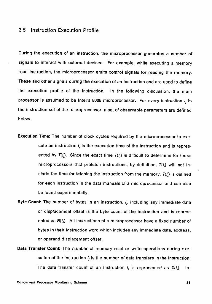
3.5 Instruction Execution Profile
During the execution of an instruction, the microprocessor generates a number of
signals to interact with external devices. For example, while executing a memory
read instruction, the microprocessor emits control signals for reading the memory.
These and other signals during the execution of an instruction and are used to define
the execution profile of the instruction. ln the following discussion, the main
processor is assumed to be lntel's 8086 microprocessor. For every instruction I, in
the instruction set of the microprocessor, a set of observable parameters are defined
below.
Execution Time: The number of clock cycles required by the microprocessor to exe-
cute an instruction I, is the execution time of the instruction and is repres-
ented by T(l,). Since the exact time T(l,) is difficult to determine for those
microprocessors that prefetch instructions, by definition, T(/,) will not in-
clude the time for fetching the instruction from the memory. T(/,) is definedv
for each instruction in the data manuals of a microprocessor and can also
be found experimentally.
Byte Count: The number of bytes in an instruction, I,, including any immediate data
or displacement offset is the byte count of the instruction and is repres-
ented as B(I,). All instructions of a microprocessor have a fixed number of
bytes in their instruction word which includes any immediate data, address,
or operand displacement offset.
Data Transfer Count: The number of memory read or write operations during exe-
cution of the instruction I, is the number of data transfers in the instruction.
The data transfer count of an instruction I, is represented as X(I,). ln-
Concurrent Processor Monitoring Scheme 31
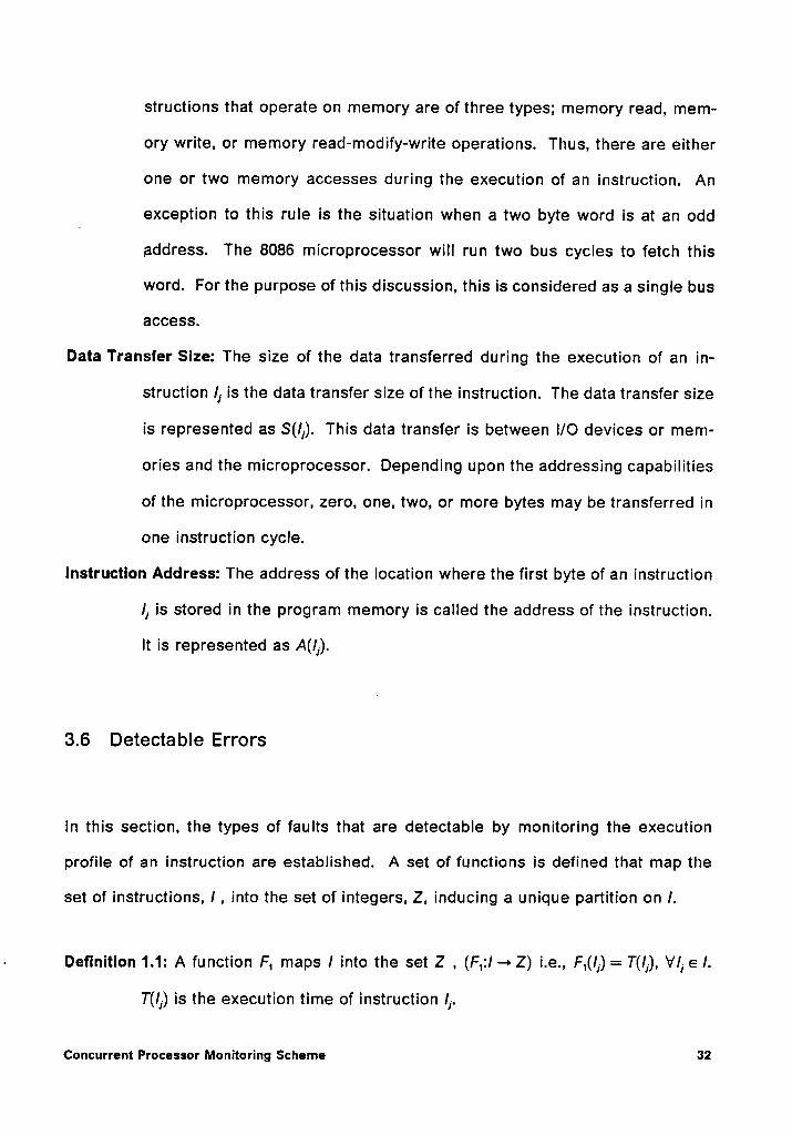
structions that operate on memory are of three types; memory read, mem—
ory write, or memory read-modify-write operations. Thus, there are either
one or two memory acoesses during the execution of an instruction. An
exception to this rule is the situation when a two byte word is at an odd
address. The 8086 microprocessor will run two bus cycles to fetch this
word. For the purpose of this discussion, this is considered as a single bus
access.
Data Transfer Size: The size of the data transferred during the execution of an in-
struction I, is the data transfer size of the instruction. The data transfer size
is represented as S(/,). This data transfer is between l/O devices or mem-
ories and the microprocessor. Depending upon the addressing capabilities
of the microprocessor, zero, one, two, or more bytes may be transferred in
one instruction cycle.
Instruction Address: The address of the location where the first byte of an instruction
I, is stored in the program memory is called the address of the instruction.
It is represented as A(I,).
3.6 Detectable Errors
ln this section, the types of faults that are detectable by monitoring the execution
profile of an instruction are established. A set of functions is defined that map the
set of instructions, I , into the set of integers, Z, inducing a unique partition on I.
- Definition 1.1: A function F, maps I into the set Z , (F,:I —»Z) i.e., F,(I,) = T(I,), VI, e I.
T(I,) is the execution time of instruction I,.
concurrent Processor Monitoring Schema 32
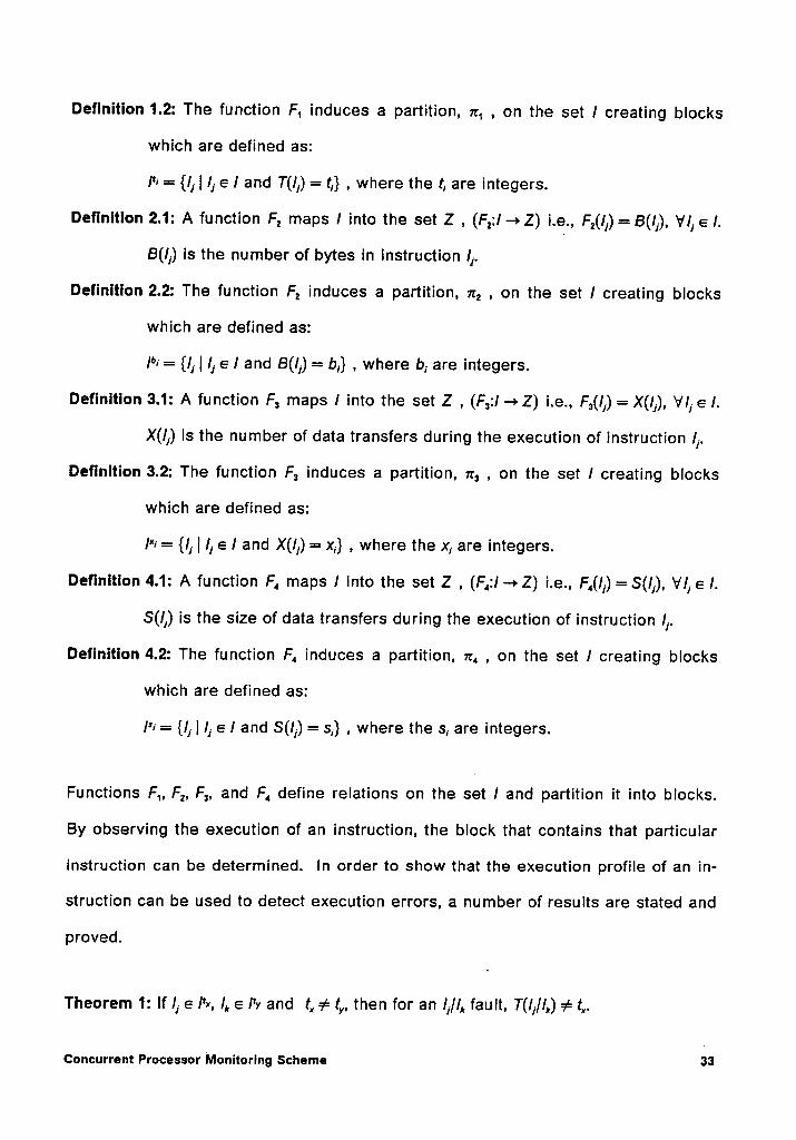
Definition 1.2: The function F, induces a partition, 7Z', , on the set I creating blocks
which are defined as:
/*1= {I, | I, 6 I and T(/,) = I,} , where the I, are integers.
Definition 2.1: A function F, maps I into the set Z , (F,:I —>Z) i.e., F,(I,) = B(/,), VI, 6 I.
B(/,) is the number of bytes in instruction I,.
Definition 2.2: The function F, induces a partition, 1:, , on the set I creating blocks
which are defined as:
/°1= {I, | I, 6 I and B(I,) = b,} , where b, are integers.
Definition 3.1: A function F, maps I into the set Z , (F,:I —>Z) i.e., F,(l,) = X(/,), VI,6 I.
X(I,) is the number of data transfers during the execution of instruction I,.
Definition 3.2: The function F, induces a partition, 1:, , on the set I creating blocks
which are defined as:
/*1 = {I, | I, 6 I and X(I,) = x,} , where the x, are integers.
Definition 4.1: A function F, maps I into the set Z , (F,:I —>Z) i.e., F,(I,) =S(I,), VI,6 I.
S(/,) is the size of data transfers during the execution of instruction I,.
Definition 4.2: The function F, induces a partition, 1:, , on the set I creating blocks
which are defined as:
/*1 = {I, | I, 6 I and S(I,) = s,} , where the s, are integers.
Functions F,, F,, F,, and F, define relations on the set I and partition it into blocks.
By observing the execution of an instruction, the block that contains that particular
instruction can be determined. In order to show that the execution profile of an in-
struction can be used to detect execution errors, a number of results are stated and
proved.
Theorem 1: If I, 6 /*¤, I, 6 /*1 and I, aI= I,, then for an /,//, fault, T(I,//,) aé I,.
ctmcumam Pm¤es¤¤•· Monmmng scmme sa
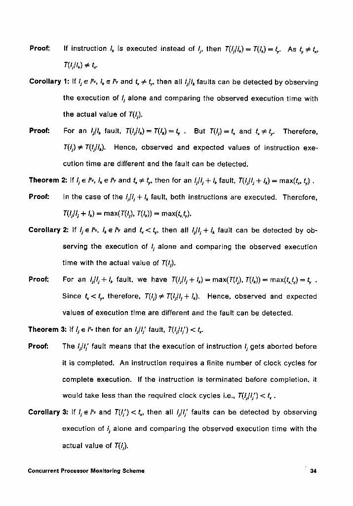
Proof: lf instruction I, is executed instead of I,, then T(I,/I,) = T(I,) = ty. As tyaé ty,
T(l,//,) ¢ t,.
Corollary 1: lf I, 6 I'¤, I, 6 IW and ty aé ty, then all /,/I, faults can be detected by observing
the execution of I, alone and comparing the observed execution time with
the actual value of T(I,).
Proof: For an I,/I, fault, T(I,/I,)= T(l,)=ty . But T(I,)=t,, and tyaéty. Therefore,
T(I,)¢ T(I,/I,). Hence, observed and expected values of instruction exe-
cution time are different and the fault can be detected.
Theorem 2: If I, 6 I*¤, I, 6 IW and t, aé ty, then for an I,/I, + I, fault, T(I,/I, + I,) = max(t,,, ty) .
Proof: In the case of the I,/I, + I, fault, both instructions are executed. Therefore,
T(I,/I, + I,) = max(T(I,), T(I,)) = max(t,,_ty).
Corollary 2: lf I,6 I*¤, I,6 IW and t,,<ty, then all I,/I,-l- I, fault can be detected by ob-
serving the execution of I, alone and comparing the observed execution
time with the actual value of T(I,).
Proof: For an I,/I,+I, fault, we have T(I,/I,+ I,)= max(T(I,), T(I,))= max(t„_ty)= ty .
Since t,,<ty, therefore, T(l,)a¢= T(I,/I,+I,). Hence, observed and expected
values of execution time are different and the fault can be detected.
Theorem 3: lf I, 6 I'¤ then for an I,/I,' fault, T(I,/I,') < t,.
Proof: The I,/I,' fault means that the execution of instruction I, gets aborted before
it is completed. An instruction requires a finite number of clock cycles for
complete execution. If the instruction is terminated before completion, it
would take less than the required clock cycles i.e., T(I,/I,’) < t, .
Corollary 3: lf I,6 I'¤ and T(I,') <t,, then all I,/I,' faults can be detected by observing
execution of I, alone and comparing the observed execution time with the
actual value of T(l,).
Concurrent Processor Mchlzcrlhg schemaI
34
Proof: For an/J/I/’
fault, T(lj//j') = T(l,') < t, . Thus, the expected and observed value
of execution times are different and the fault can be detected.
Theorem 4: lf /1 e l'¤ and t, > 1, then for an fault, (IJ) > T(qS).
Proof: ln the case of an I,/¢> fault, no instruction is executed. Since there is no
permanent damage, the microprocessor would fetch the next instruction for
execution. Thus T(lj/¢>) = T(q5) = 1. As all instructions require more than 1
clock cycle for execution (e.g., in the 8086 microprocessor), T(l,)>1 and
TU;) > T(¢>) -Corollary 4: lf lje /'¤ and t,„¢ T(qS), then all I,/¢> faults can be detected by observing
execution of instruction I, anddeterminingProof:
For an /,/43 fault, T(/I/¢>)= T(¢>)= 1. But for any instruction in the 8086
microprocessor, T(/I) > 1 . Thus the expected and observed execution time
values are different and the fault is detected.
Theorems 1 through 4 can similarly be proved for each of the other parameters i.e.,
B(/J), X(I,), and S(lj), defined earlier.
ln the case of an I]/I, fault, the behavior of the microprocessor-is difficult to predict.
For example, it has been found that some illegal opcode patterns of the 8085 micro-
processor actually perform certain operations not included in the documentation. lt
has been suggested that these opcodes can be used to enhance programming [87].
Since these operation modes are not supported by the manufacturer, it is possible
that a device from a different production run may operate differently. Therefore, un-
defined opcodes should not be used and instead treated as illegal instructions. Some
modern processors have built-in illegal opcode detectors e.g., Motorola’s 68000 and
Concurrent Processor Monitoring Schema 35
68020, as well as InteI’s 80286 and 80386 each have illegal opcode detectors. All I,//„
faults can be detected by these detectors.
Errors in addressing logic can result in an I,, I,/I,, I,„ fault. In order to detect this fault,
it is necessary to have information about the dynamic behavior of the executing pro-
gram. The following theorem provides the basis for monitoring an instruction se-
quence.
Theorem 5: The address of an instruction I,, that succeeds instruction I, , barring any
jump or interrupts, is A(l,) = A(I,) + B(I,) .
Proof: The execution of instructions is sequential in a program unless a jump or
interrupt instruction is encountered. The address of instruction I, is A(I,).
Since the length of the instruction I, is B(I,) bytes, the next sequential in-
struction I, must be located at A(I,) = A(I,) + B(I,) .
Corollary 5: For any sequence of instructions I, followed by I, , a control flow error can
be detected by comparing the address of instruction I,, i.e., comparing
A(l,) with A(I,) + B(I,).
Proof: Since I, and I, are sequential, A(I,) = A(I,) + B(l,). Thus, any control flow er-
ror that produces a next address which is different from A(I,) is detected.
The response of a microprocessor to an /,/;.1 fault may depend upon its particular ar-
chitecture. For instance, consider the 8086 microprocessor. It has a built—in queue
for prefeteching instructions. An incorrect queue update signal can result in over or
underflow of the queue. This can be detected by a watchdog processor that tracks
the operation of the microprocessor’s queue by maintaining a copy ofthe queue and
updating it whenever there is a queue operation.
Concurrent Processor Monitoring scnorno 36
The 8086 microprocessor differentiates between data and program memory locations
and addresses them differently using separate segment registers. Thus, an ad-
dressing error which results in access to program memory instead of data memory
or vice versa can be detected if the watchdog processor knows the type of access
required. Another type of memory addressing problem may result when the address
of a non-existent memory location is generated. This is called undefined memory
that does not exist physically. An address checking mechanism can be used to cover
this type of fault. A stack is indispensable for subroutine calls. A change in the value
of stack pointer can result in loss of the return address. This type of error can be
detected by monitoring the value of the stack pointer in the monitoring hardware. .
3.7 Detection Mechanisms _
In order to utilize the concepts developed in the preceding sections, a number of
detection mechanisms are needed. These detection mechanisms can be classified
into two categories; generic mechanisms and processor—specific mechanisms. A
generic mechanism is conceptually applicable to any microprocessor. Generic
mechanisms can be further classified as instruction-related or processor-related. An
Instruction-related generic mechanism detects an error by monitoring the execution
of an instruction. Detection mechanisms based on the execution profile of an in-
struction are classified as instruction-related generic mechanisms. These include
mechanisms that will be defined later as: execution time check (ETC), byte count
check (BCC), data transfer check (DTC), data size check (DSC), and next address
check (NAC). On the other hand, a processor-related generic mechanism monitors
a specific characteristic of the processor. This category is comprised of illegal
Concurrent Processor Monitoring Scheme 37
opcode check (IOC), stack address check (SAC), and undefined memory access
check (UMA). These mechanisms are defined later.
A processor-specific mechanism makes use of a unique feature of the micro-
processor that may not be available in other processors. For an 8086 micro-
processor, these mechanisms, to be defined later, include improper queue signals
(IQS) and improper memory access (IMA). A distinction Is made here between a
processor-related generic mechanism and a processor-specific mechanism in that
the former monitors a characteristic of the processor that is common to most
processors e.g., stack operations, illegal opcodes etc., and the Iatter observes
processor characteristics that are not shared by every processor e.g., the Instruction
prefetch queue in the 8086 microprocessor. A list of all detection mechanisms for an
8086 microprocessor Is shown in Table 1. These mechanisms are formally defined
in Chapter 4. The 8086 microprocessor was chosen for this work so that processor
specific mechanisms can be implemented.
Concurrent Processor Monitoring Schema 38
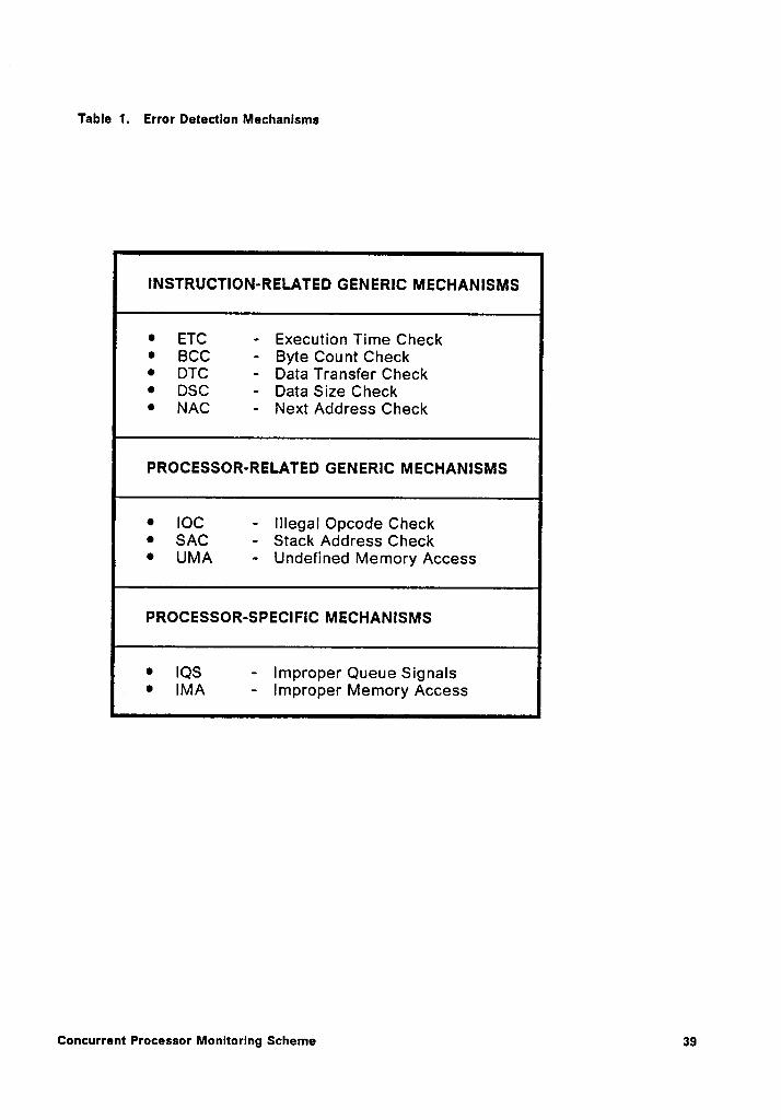
Table 1. Error Detectlon Mechanlsms
INSTRUCTION-RELATED GENERIC MECHANISMS
•ETC - Execution Time Check•BCC - Byte Count Check• DTC · Data Transfer Check• DSC - Data Size Check• NAC - Next Address Check
PROCESSOR-RELATED GENERIC MECHANISMS
•IOC - Illegal Opcode Check• SAC - Stack Address Check•UMA - Undefined Memory Access
PROCESSOR—SPECIFlC MECHANISMS
•IQS - Improper Queue Signals•IMA - lmproper Memory Access
Concurrent Processor Monitoring Scheme 39
Chapter 4
Design Implementation
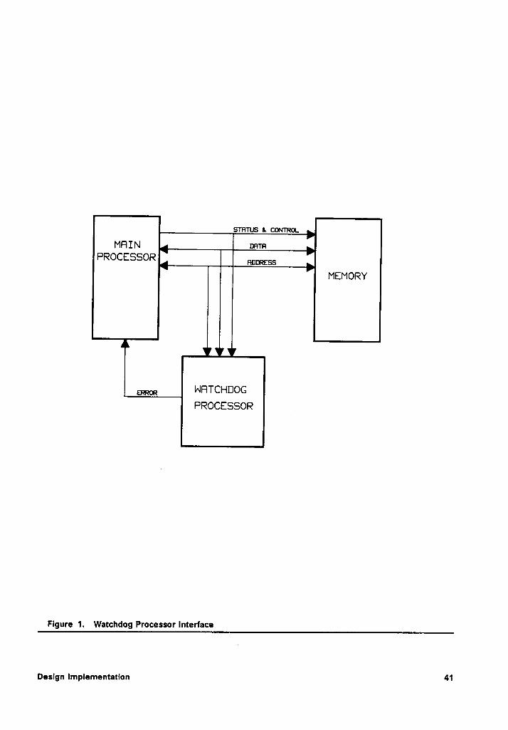
Implementation of the proposed concurrent processor monitoring (CPM) scheme re-
quires a watchdog processor (WDP) that is capable of determining the state of the
microprocessor by observing its status and control lines and traffic on the system
bus. An interface between the microprocessor, hereinafter referred to as the main
processor, and its watchdog processor is shown in Figure 1. In the following
sections, design requirements for the watchdog processor are outlined and details
of all detection mechanisms are discussed.
4.1 Design Requirements
The WDP is to implement a scheme that monitors a set of observable features of the
main processor. Although the concept of observable features is quite general, its
actual implementation is highly processor specific. Design of the WDP is strongly
influenced by the architecture of the main processor because there is large variation
in the characteristics between different microprocessors. This implies that it is not
Deslgn Implementation 40
5'TFITUS & CONTROL
mn
_ll
PROCESSORlll mm
IIMEMORY
ERROR MRTOHDOGRROOESSOR V
Figure 1. Watchdog Processor Interface
Design Implementation 41
feasible to design a single general purpose WDP to go along with every micro-
processor. The design of the WDP should satisfy the following requirements [35]:
1. lt should not interfere with the normal operation of the main processor.
2. lt should be able to determine the state of the main processor by monitoring its
external status and control signals and bus traffic. Faults should be detected on
the basis of this information.
3. lt should have low-complexity logic so that hardware overhead can be kept to a
minimum.
4. It should have high fault coverage.
5. It should have low fault detection latency so that error propagation can be mini-
mized.
4.2 8086 Basics
The CPM scheme presented here is for an 8086-based system. Therefore, some
comments about the architecture of the 8086 microprocessor are in order. The 8086
CPU consists of two functional units; the execution unit (EU) and the bus interface unit4
(BIU). The two units operating independently are able, most of the time, to overlap
instruction fetch with instruction execution and thus optimize the use of the system
bus. The EU performs all arithmetic/logic operations and depends upon the BIU for
all bus accesses. An instruction queue is maintained in the CPU. Usually this queue
contains at least one byte from the instruction stream and thus the EU does not have
to wait for an instruction to be fetched. If the EU executes a jump instruction or needs
data from a memory location, it requests that the BIU make a bus access. The BIU
Design Implementation 42
either drops its current operation to perform the requested fetch or delays the re-
quest by one clock cycle.
The 8086 microprocessor has two modes of operation; minimum mode and maximum
mode. When operating in the maximum mode, the 8086 provides information about
instruction queue operations through lines qs0 and qs1. The queue has four modes
of operation: no operation (qsO,qs1=0,0), first byte of an instruction taken from the
queue (qs0,qs1=0,1), queue reinitialized (qs0,qs1=1,0), and subsequent byte of an
instruction taken from the queue (qsO,qs1 = 1,1). The CPU has eight types of bus cy-
cles that are encoded on lines s0', s1' and s2'. These types include: interrupt ac-
knowledge, read I/O, write l/O, halt, instruction fetch, read memory, write memory,
and no operation. The external processor uses these status signals to determine the
type of operation being performed by the CPU [93].
4.3 Execution Profile Verification
Information about the expected execution parameters of an instruction (i.e.,
T(l,), B(lj), S(Ij), and S(lj)) can be obtained either from the data manuals of the micro-
processor or observed experimentally. This information is programmed into a PLA
in the WDP. This is called the Instruction profile table (IPT). At the time of execution,
the WDP monitors bus traffic and fetches instruction opcodes along with the main
processor. lt partially decodes the instructions in parallel with the main processor
and reads their corresponding parameters from the IPT. The WDP also observes the
instruction parameters concurrently as execution progresses. After completion of the
execution of an instruction, the parameter values read from the IPT are compared
Design Implementation 43
with the ones observed concurrently to detect any error. The WDP resets its moni-
toring logic in conjunctlon with the beginning of the next instruction. The address of
every instruction executing on the main processor can be noted directly from the
address bus. This address information is used by the address verification scheme to
be discussed later. The algorithm for detection of execution errors is described be-
low.
4.3.1 The Execution Profile Verification Algorithm
1. Calculate (or experimentally determine) for each instruction, the parameters
T(lj), B(/I), X(lj), and S(lj) , and save them in the IPT.
2. Initialize the next address value in the WDP.
3. For the next instruction fetched by the main processor, the WDP must:
_a. verify the address of the newly fetched instruction by comparing it with the
next address value calculated in the previous instruction cycle. This step is
omitted if the current instruction is the first instruction of the program.
b. partially decode the instruction to determine its type and read its execution
profile from the lPT.
c. observe the actual execution profile on-line.
4. Upon completion of the instruction, compare the observed execution profile with
the profile read from the IPT.
5. lf the two execution profiles do not match, signal an error. Else go to step 3.
Design Implementation 44A
4.3.2 Discussion
This algorithm, by design, checks the execution profile of an instruction following the
execution of the instruction. Thus, an error that produces an incorrect execution
profile would be detected after the faulted instruction is completed. This observation
implies that the error detection latency in these cases would be less than two in-
struction cycles.
4.4 Address Verification
Faults in the addressing logic of the microprocessor produce control flow errors that
can be detected by the next address verification scheme. This scheme detects any
breaks in the sequence of addresses of sequential instructions. The step 3(a) of the
execution profile verification algorithm described in section 4.3.1 calls for address
verification of every instruction fetched for execution. The details of this process are
described by the following algorithm.
4.4.1 The Next Address Verification Algorithm
1. Initialize valid_next__address = NO.
2. Read the address of the next instruction. Set present_address = the address of
the new instruction.
3. lf va/id_next_address = YES, compare the present_address with next_address.
lf present__address = next_ac/dress, the address of the new instruction is vali-
dated. Else indicate an error.
Design Implementation 45
4. If the new Instruction is not a jump Instruction, set va/id_next_address = YES and
offset = insi‘r_/ength and goto step 6. The Instruction length Is in the IPT.
5. lf the new Instruction is a jump Instruction, and the offset for the jump destination
is encoded in the Instruction, set valid_next__address = YES and offset =
jump_offset and go to step 6. Else set va/id_next_address = NO and go to step
6.
6. Set next__address = present_address + offset.
7. Go to step 2.
4.4.2 Discussion
The executing Instruction Is partially decoded by the WDP to determine If It Is a jump
Instruction and Its length I.e., B(/j), is read from the IPT. Upon fetching the next in-
struction, Its address Is checked against the previously calculated next address to
ensure that correct Instruction I.e., one from the correct address, has been fetched.
As the address of the next Instruction is always calculated during the execution ofthe
current InstructIon,_there will not be a next_address during execution of the first In-
struction of a program. An initialization flag I.e., va/id_next_address, Is used to tell
the WDP not to test the next_address of the first Instruction of a program.
Most programs have blocks of 8 to 10 sequential instructions followed by a jump in-
struction [64]. Jump Instructions are of three types; conditional jumps, unconditional
jumps, and Interrupts. Since unconditional jumps are always taken, the address of
the next Instruction Is included as part of the opcode and can be calculated by the
WDP. An exception to this rule Is the case when an unconditional jump to a desti-
nation Is taken whose address depends upon some data value in a register or mem-
Design Implementation 46
ory location, e.g., a jump through a register. Since the contents of a data register is
not observable by the WDP, it may not be possible for the WDP to calcuiate the ad-
dress of the next instruction. Therefore, this algorithm does not verify the next ad-
dress following a jump through memory or register instruction. An error in the
destination address of such an instruction is not detected. However, the WDP does
check to ensure that a jump is taken.
ln the case of a conditional jump instruction, there are two possible destinations; a
jump address or the next sequential address. The choice between these two paths
generally depends upon some condition flag. As the WDP has no access to the con-
dition flags, it may not be able to make a determination about the correct next ad-
dress. However, the WDP has a knowledge of both the addresses and can detect an
error if an instruction is fetched from an address which is different from these two
addresses.
From the program execution point of view, an interrupt has the effect of producing a
jump operation. This is similar to an unconditional jump except that the program
control returns to this location after the completion of the interrupt service routine
and additional clock cycles are used for storing return address. Hence, the WDP
treats an interrupt as an unconditional jump.
4.5 Additional Detection Nlechanisms
The detection mechanisms discussed so far belong to the class of instruction—related
generic mechanisms. In order to increase the fault coverage of the WDP, additional
mechanisms are needed. These include processor-related generic mechanisms and
Design Implementation · 47
processor specific mechanisms. The specific mechanisms in the context of the 8086
microprocessor are considered next.
Processor-related generic mechanisms include: Illegal Opcode Check (IOC), Stack
Address Check (SAC), and Undefined Memory Access Check (UMA). The WDP has
a complete list of all valid opcodes and their parameters are contained in the IPT.
Therefore, any opcode pattern that is not in the IPT is considered an illegal instruc-
tion. Thus, an illegal opcode detector can be implemented at virtually no extra cost.
The illegal opcode detector is useful only if the fault occurs in the program memory
or the system bus. An I)/I, fault inside the processor cannot be detected because the
Instruction register of the processor is not visible to the WDP. However, this fault
may produce other errors that could be detected either by the IOC mechanism or one
of the other mechanisms.
A copy of the stack pointer is maintained by the WDP. lt is verified and updated
whenever there is a stack operation. Thus, if an error changes the contents of the
stack pointer register, the error can be detected the next time the stack is used.
Certain addressing errors can result in access to an undefined memory location. A
special circuit designed to detect this type of memory access has also been included
in the WDP. All available memory locations and memory mapped devices are fully _
decoded so that they have unique addresses.
Processor specific mechanisms for the 8086 microprocessor include: Improper
Queue Signals Check (IQS) and Improper Memory Access Check (IMA). An Improper
queue update signal may result in an attempt to read from the queue when it is empty
or to write into the queue when it is full. A queue overflow or underflow due to an
incorrect queue update signal must be detected. The queue pointer points to the
Design Implementataen”
48
lowest address, zero in this case, if the queue is empty and to the highest address,
six in this case, ifthe queue is full. An improper queue update signal can be detected
by tracking the value of the queue pointer and verifying that it is within the above
mentioned address bounds.
An IMA results when the main processor generates a read memory cycle for fetching
data but the addressed memory location is in the program memory area or vice
versa. The WDP can determine the type of memory access cycle being executed by
the 8086 by observing the status signals of the 8086. Hence, an addressing error that
produces access to incorrect type of memory location can be detected by the WDP.
4.6 Watchdog Processor Architecture for the 8086
The architectures of modern microprocessors make it difficult to observe their
internal registers and internal control signals. Ideally, a fault detection mechanism
should be able to determine the state of the main processor at all times. This is ac-
complished by monitoring some observable features of the main processor. The only
observable features of a microprocessor are its I/O pins. The WDP is designed to
monitor the traffic on the address, data, and control buses to determine the state of
the main processor.
To monitor the execution parameters of an instruction, the WDP must know the par-
ticular instruction under execution on the main processor. This information is not
easily available on those microprocessors that have instruction prefetch queues be-
cause the memory read and write signals for instruction fetches are not synchronized
with the execution of the instructions. This is the case for the 8086 microprocessor.
Design implementation 49
However, the 8086 microprocessor provides status signals (s2,s1,s0) to indicate the
type of bus cycle being run. lt also provides queue status signals (qs1,qsO) that may
be interpreted to determine the instruction that is currently being executed on the
processor. Status signals for code/data segments are also provided to indicate the
particular memory segment being accessed. This information can be used by the
WDP to determine the particular instruction being executed by the main processor,
the memory segment being addressed, and the type of bus cycle being run at any
time. This suggests that the WDP must have an elaborate bus tracking mechanism
and an instruction queue similar to the main processor. In addition, the WDP should
also have an address queue to store the addresses of all instructions in the queue.
This information is needed for address verification of the next instruction. A block
diagram of the WDP architecture is shown in Figure 2. Architectural details of the
individual mechanisms are described in the following sections.
4.6.1 Execution Time Check (ETC)
The number of clock cycles required for complete execution of an instruction is the
execution time of the instruction. lt is measured as the number of clock cycles be-
tween two consecutive instruction fetch signals. As mentioned earlier, the BIU of the
8086 microprocessor may sometimes delay a bus access request from the EU. This
delay must be accounted for when the total instruction execution time is computed.
The ETC design incorporates the necessary provision for determining these lost cy-
cles. Lost bus cycle delay is subtracted from the observed execution time before
comparing the actual execution time with the expected execution times as contained
in the IPT. A block diagram of the ETC mechanism is shown in Figure 3. The com-
pletion of an instruction is implied when the main processor fetches the first byte of
Design Implementation 50
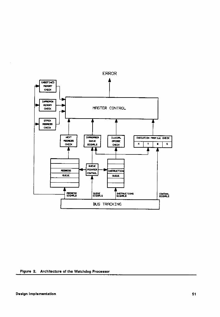
ERROR
Luzrzrznraum¤¢¤<
!n¤¤¤¤¤¤ammvam MHSTER CONTROLsmcx
nmcss¤:¤<
rcxr xwmenzn zu.1:¤1 zxzcurzou morxu: ¤·:¤<mutss anzu: orcorz¤·==< ==<=·¤ ¤=¤< Ä * EH_-
M ÄPomn:2_mßmm—
-
—
-6:11% nun.: rrsnmcrxous oormaa.szans szoas smas SIGH.S
BUS TRFICKING
Flgure 2. Archltecture ol the Watchdog Processor
Deslgn Implementation 51
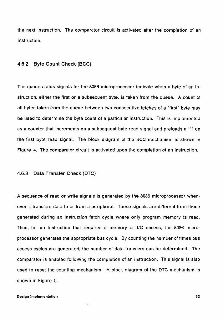
the next instruction. The comparator circuit is activated after the completion of an
instruction.
4.6.2 Byte Count Check (BCC)
The queue status signals for the 8086 microprocessor lndlcate when a byte of an in-
struction, either the first or a subsequent byte, is taken from the queue. A count of
all bytes taken from the queue between two consecutive fetches of a "first" byte may
be used to determine the byte count of a particular instruction. This is implemented
as a counter that increments on a subsequent byte read signal and preloads a’1’
on
the first byte read signal. The block diagram of the BCC mechanism is shown in
Figure 4. The comparator circuit is activated upon the completion of an instruction.
4.6.3 Data Transfer Check (DTC)
A sequence of read or write signals is generated by the 8086 microprocessor when-
ever it transfers data to or from a peripheral. These signals are different from those
generated during an instruction fetch cycle where only program memory is read.
Thus, for an instruction that requires a memory or I/O access, the 8086 micro-
processor generates the appropriate bus cycle. By counting the number of times bus
access cycles are generated, the number of data transfers can be determined. The
comparator is enabled following the completion of an instruction. This signal is also
used to reset the counting mechanism. A block diagram of the DTC mechanism is
shown in Figure 5.
Design Implementation 52
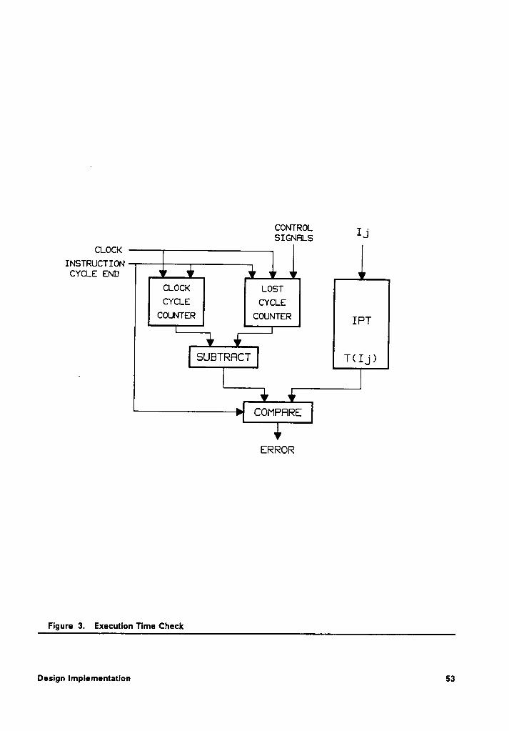
CONTROL -SIGNHLS IJCLOCK
INSTRUCTIONCYCLEEND‘
CLOCK LOSTCYCLE CYCLE
COUNTER COUNTER IF,-T
SUBTRHCT T( I_j)
COMPFIRE
ERROR
Figure 3. Execution Time Check
Design Implementation 53
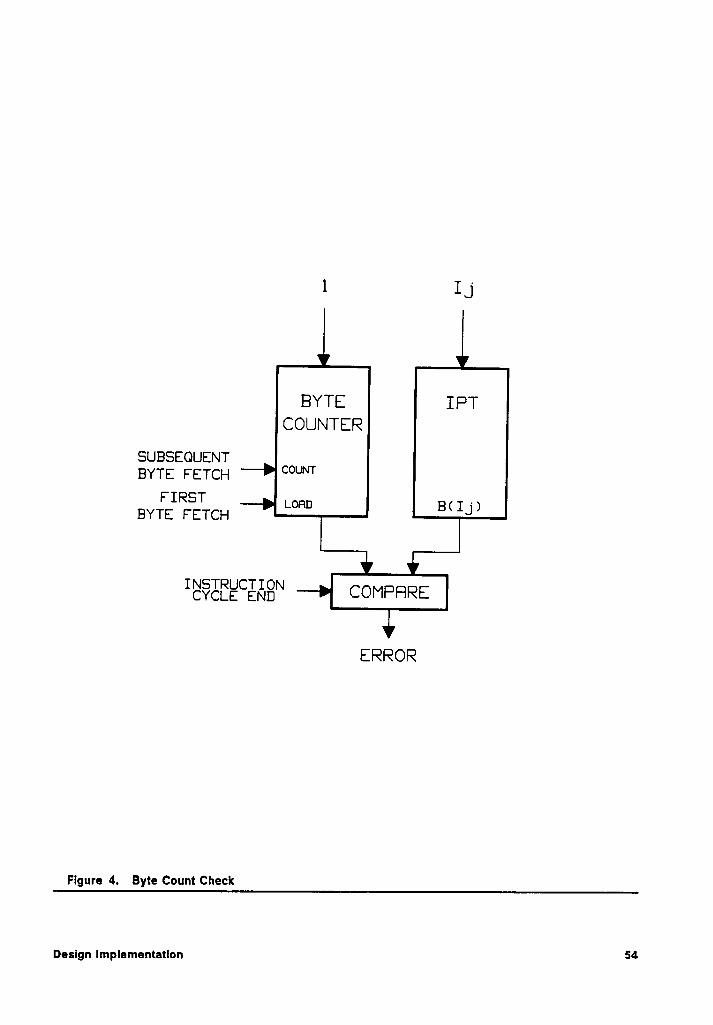
1 I _j
BYTE IRTCOUNTER
SUBSEQUENTBYTE FETCH °°U'"
FIRST .BYTE EETEH LORD BHV
INSTRUCTIONCYCLE END COMPFTRE
ERROR
Figure 4. Byte Count Check
Design Implementatlon 54
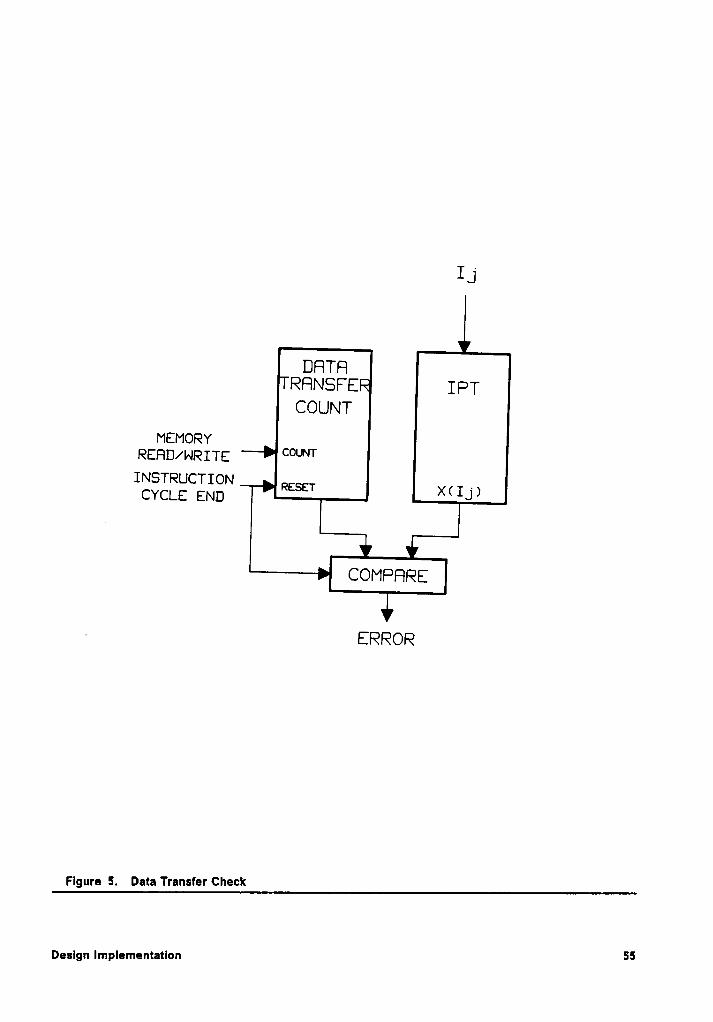
IJ
DFITRRRNSFE ä IRTCOUNT
MEMORYREFID/WRITE COUNT
RESET ><<¤>
COMRRRE
- ERROR
Flgure 5. Data Transfer Check
ssDesign Implementation
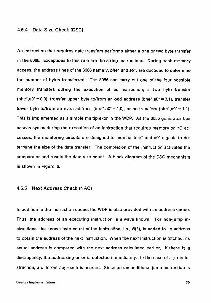
4.6.4 Data Size Check (DSC)
An Instruction that requires data transfers performs either a one or two byte transfer
in the 8086. Exceptions to this rule are the string Instructions. During each memory
access, the address lines of the 8086 namely, bhe* and aO", are decoded to determine
the number of bytes transferred. The 8086 can carry out one of the four possible
memory transfers during the execution of an Instruction; a two byte transfer
(bhe*,a0' =0,0), transfer upper byte to/from an odd address (bhe",a0' =0,1), transfer
lower byte to/from an even address (bhe',a0'= 1,0), or no transfers (bhe',a0'= 1,1).
This Is implemented as a simple multiplexor in the WDP. As the 8086 generates bus
access cycles during the execution of an Instruction that requires memory or l/O ac-
cesses, the monitoring circuits are designed to monitor bhe' and a0' signals to de-
termine the size of the data transfer. The completion of the Instruction activates the
comparator and resets the data size count. A block diagram of the DSC mechanism
is shown In Figure 6.
4.6.5 Next Address Check (NAC)
In addition to the Instruction queue, the WDP is also provided with an address queue,
Thus, the address of an executing Instruction is always known. For non-jump in-
structions, the known byte count of the Instruction, I.e., B(lj), is added to its address
to obtain the address of the next Instruction. When the next Instruction Is fetched, its
actual address Is compared with the next address calculated earlier. If there is a
discrepancy, the addressing error is detected immediately. ln the case of a jump in-
struction, a different approach is needed. Since an unconditional jump Instruction is
Design Implementation 56
IJ
DRTRSIZE IPT
COUNT
bh6*(FROM CPU)
a@* St IJ)(FROM CPU)
I§$·EEE"E„£8'“ COMPHRE
ERROR
Flgure 6. Data Slze Check
Deslgn Implementatlon 57
always taken, the next address is checked to ensure that a jump was taken. Many
instructions include the destination address in the instruction word following the
opcode. If the destination address is included in the jump instruction, the next ad-
dress is checked to ensure that program execution resumed at the proper address.
lf the destination address is not available because it depends on some data value in
a register or a memory location, the only available option is to verify that a jump was
taken. The destination address cannot be verified in this case.
A conditional jump instruction is taken depending upon the status of a condition flag.
For this type of instruction, if the jump address is included in the instruction, both the
next sequential address and the jump address are calculated by the WDP. The next
instruction executed must come from one of these two addresses. An error is de-.
tected ifa jump to an address that is different from the two calculated addresses is
made. However, this mechanism will not detect an error ifa incorrect branch is made
because the condition flag was in error. The algorithm for this scheme is described
in Section 4.4. A block diagram of the NAC mechanism is shown ln Figure 7.
4.6.6 Illegal Opcode Check (IOC)
A list of all valid opcode patterns ls available in the IPT. An opcode that cannot be
found in this list by the WDP is declared an illegal instruction. The IPT can be im-
plemented as a PLA so that all illegal opcodes can be detected in one cock cycle.
Additionally, the coding scheme of the instruction set of the 8086 makes it possible
to implement the IPT as a very compact PLA. This mechanism can only detect errors
that occur in program memory or on the system bus. An illegal opcode produced due
to an upset in the instruction register of the main processor cannot be detected by
Design Implementation 58
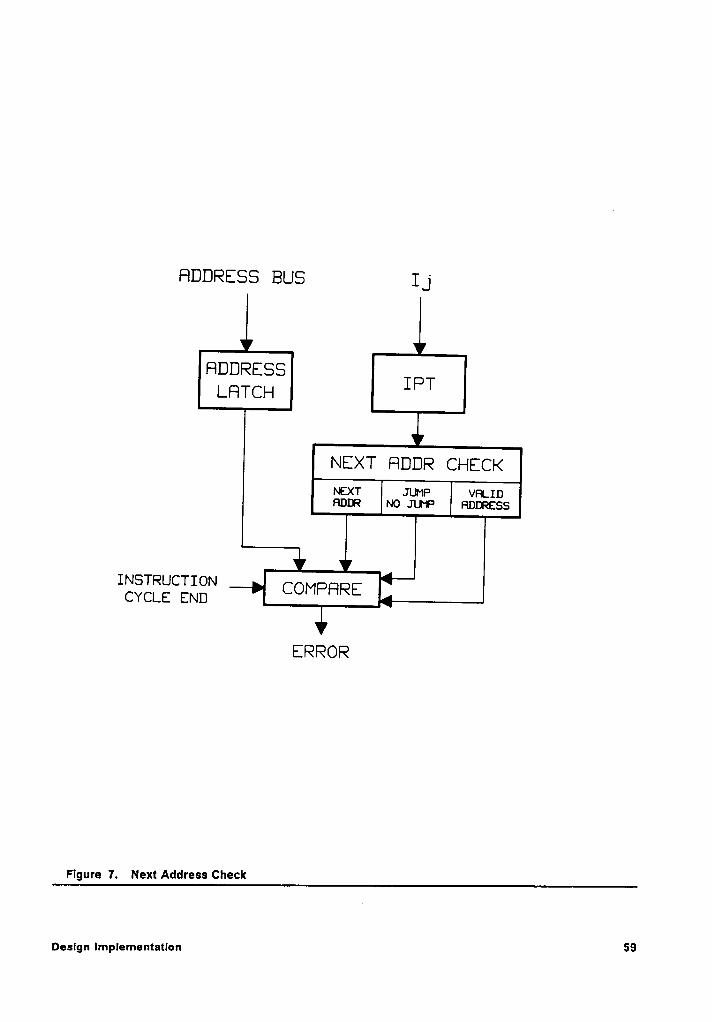
FIDDRESS BUS I _j
FIDDRESSLRTCH IPT
NEXT HDDR CHECK~ExT JUMP vP¤.1¤Panne Mo JUr·¤= Pmnazss
INSTRUCTION JCYCLE END COMPHRE
. ERROR
Figure 7. Next Address Check
Design Implementation 59
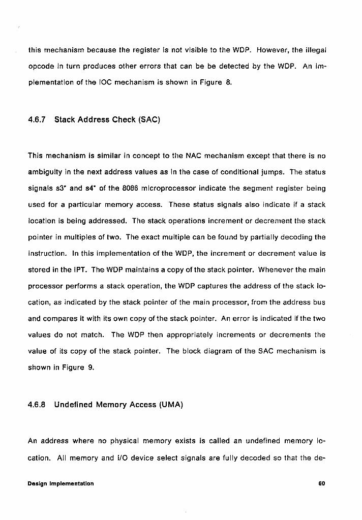
. this mechanism because the register is not visible to the WDP. However, the illegal
opcode in turn produces other errors that can be be detected by the WDP. An im-
plementation ofthe IOC mechanism is shown in Figure 8.
4.6.7 Stack Address Check (SAC)
This mechanism is similar in concept to the NAC mechanism except that there is no
ambiguity in the next address values as in the case of conditional jumps. The status
signals s3' and s4* of the 8086 microprocessor indicate the segment register being
used for a particular memory access. These status signals also indicate if a stack
location is being addressed. The stack operations increment or decrement the stack
pointer in multiples of two. The exact multiple can be found by partially decoding the
instruction. ln this implementation of the WDP, the increment or decrement value is
stored in the IPT. The WDP maintains a copy of the stack pointer. Whenever the main
processor performs a stack operation, the WDP captures the address of the stack lo-
cation, as indicated by the stack pointer of the main processor, from the address bus
and compares it with its own copy ofthe stack pointer. An error is indicated ifthe two
values do not match. The WDP then appropriately increments or decrements the ·
value of its copy of the stack pointer. The block diagram of the SAC mechanism is
shown in Figure 9.
4.6.8 Undefined Memory Access (UMA)
An address where no physical memory exists is called an undefined memory lo-
cation. All memory and l/O device select signals are fully decoded so that the de-
Design Implementation 60
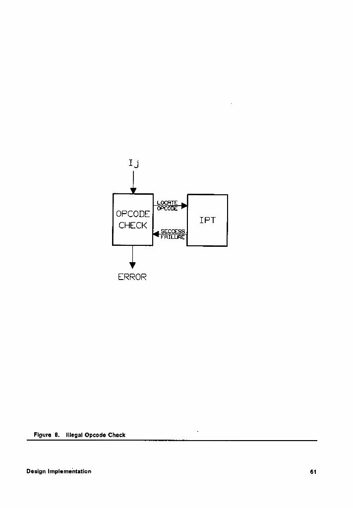
I J
ääääääORCODE T PTCHECK saccsssrauen:
ERROR
Figure 8. Illegal Dpcode Check '
Design Implementation 61
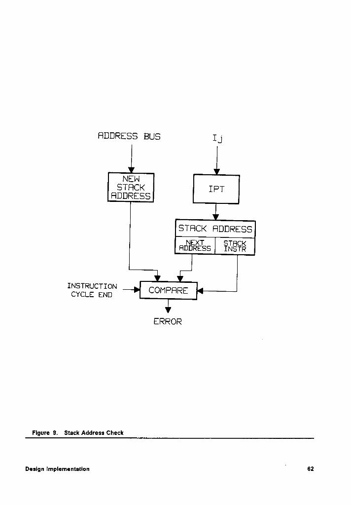
RDDRESS BUS I _j
NEWSTRCK IRT
RDDRESS
STRCK RDDRESSNEXT STFICKFIDDRESS INSTR
INSTRUCTION {
CYCLE END COMPQRE
ERROR
Flgure 9. Stack Address Check
' 62Deslgn Implementation
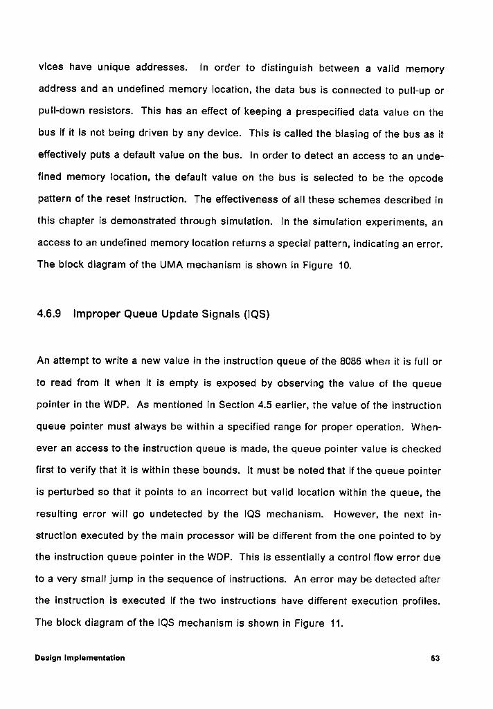
vices have unique addresses. ln order to distinguish between a valid memory
address and an undefined memory location, the data bus is connected to pull-up or
puII·down resistors. This has an effect of keeping a prespecified data value on the
bus if it is not being driven by any device. This is called the biasing of the bus as it
effectively puts a default value on the bus. In order to detect an access to an unde-
fined memory location, the default value on the bus is selected to be the opcode
pattern of the reset instruction. The effectiveness of all these schemes described in
this chapter is demonstrated through simulation. ln the simulation experiments, an
access to an undefined memory location returns a special pattern, indicating an error.
The block diagram of the UMA mechanism is shown in Figure 10.
4.6.9 lmproper Queue Update Signals (IQS)
An attempt to write a new value in the instruction queue of the 8086 when it is full or
to read from it when it is empty is exposed by observing the value of the queue
pointer in the WDP. As mentioned in Section 4.5 earlier, the value of the instruction
queue pointer must always be within a specified range for proper operation. When-
ever an access to the instruction queue is made, the queue pointer value is checked
first to verify that it is within these bounds. lt must be noted that if the queue pointer
is perturbed so that it points to an incorrect but valid location within the queue, the
resulting error will go undetected by the IQS mechanism. However, the next in-
struction executed by the main processor will be different from the one pointed to by
the instruction queue pointer in the WDP. This is essentially a control flow error due
to a very small jump in the sequence of instructions. An error may be detected after
the instruction is executed if the two instructions have different execution profiles.
The block diagram of the IQS mechanism is shown in Figure 11.
Design Implementation 63
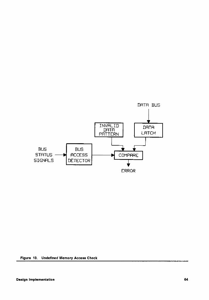
DRTR BUS
INVRLIDDRTR DHTHPRTTERN LHTCH
BUS BUSSTRTUS RCCESS COMPRRE
SIGNRLS DETECTOR
ERROR
Flgure 10. Undeflned Memory Access Check
Design Implementation 64
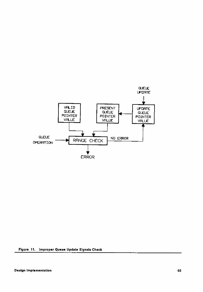
OUEUEUPDHTE
VFILID PRESENT UPDFITEOUEUE OUEUE OUEUE
POINTER POINTER POINTERVFILUE VFILUE VHLUE
OUEUE NO ERROROPERHTION RFINGE CHECK
ERROR
Flgure 11. lmproper Queue Update Slgnals Check
Deslgn Implementation G5
4.6.10 lmproper Memory Access (IMA)
The 8086 microprocessor addresses data and instruction memories differently. lt
uses the DS segment register for calculating the physical address of data and CS
segment register for determining an instruction byte location. An /I/pi fault can cause
the microprocessor to use an incorrect segment register or make it access instruc-
tion memory when an access to data memory is required. This is detected by ob-
serving the segment register used for memory access during execution of an
instruction. By noting the type of instruction executing on the main processor the
WDP determines the type of bus access cycles that may be required. Therefore, the
WDP can detect an error if an incorrect segment register is used for accessing a data
or memory location. The block diagram of the IMA mechanism is shown in
Figure 12.
Design impiemenzeuen 66
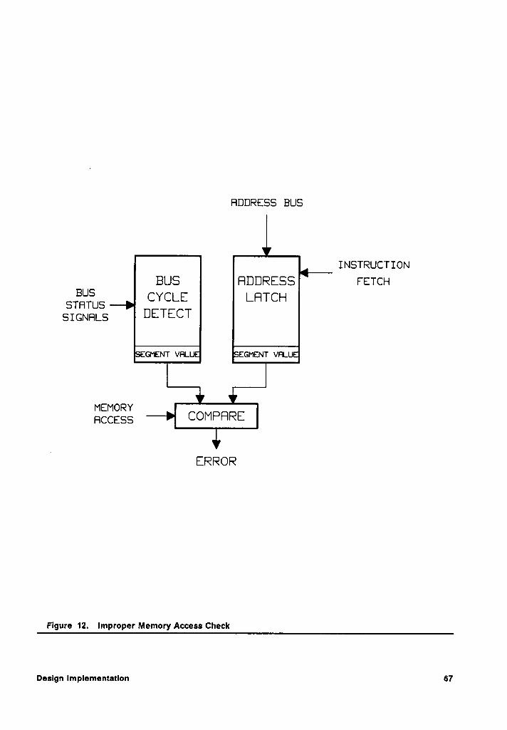
FIDDRESS BUS
INSTRUCTIONBUS FIDDRESS Farce-:
BUSSTHTUS CYCLE LFITCH
SIGNFILS DETECT
EGMENT VHL. : EGMENT VHL ¤
MEMORYHCCESS COMPFIRE
IERROR
Flgure 12. lmproper Memory Access Check
Design Implementation 67
Chapter 5
Concept Verification
ln order to demonstrate the effectiveness of the proposed concurrent processor
monitoring (CPM) scheme, a WDP is implemented for the 8086 microprocessor. A
small prototype system is designed to assess the performance of the WDP. The de-
tails of the testing and verification process are described in this chapter.
5.1 The Need for Simulation
Transient faults can be artificially induced in a digital system by either exposing it to
high energy radiations or introducing transients in its power supply
[15-17,20-26,40,41]. Neither are controlled events and introduce random upsets
whose time and place of occurrence are non~deterministic. Computer simulatlons
are used to overcome this lack of specificity in time and location of transient faults.
The effect of an SEU on a digital the system can be modeled in a simulation envi-
ronment by injecting transient faults at a particular time and location in a precise
manner. Another advantage of computer simulation is that any fault can be recreated
Concept Veriflcatlon 68
any number of times to study its effects in detail. The performance of the main
processor and its WDP after the injection of a fault, especially its internal signals, can
be observed by using the trace option of the simulator.
ln light of the above mentioned arguments, computer simulations are- used to study
the the effect of an SEU on the prototype system and the performance of the WDP.
During each simulation run, one transient fault is injected while the main processor
executes a test program. A large number of simulation runs are required to collect
data that is statistically significant.
5.2 Level of Simulation
The next step is to decide upon the level of simulation. Gate level models have been
extensively used in simulating SSI and MSI circuits. This approach requires detailed
gate level information about the circuit that is usually not available for more complex
LSI and VLSI circuits. Even if this information were available, the complexity of many
VLSI devices such as microprocessors etc, makes modeling at the gate level infea-
sible due to high cost of writing the models and the computational resources required
to run the simulation. Many computer hardware description languages such as
VHDL, HILO, ISP' or GSP—2, can model circuits at a higher level of abstraction called
the functional level. At this level, the device is modeled by its register transfer
characteristics wherein a detailed knowledge of its gate level implementation is not
required [88]. Although functional modeling and simulation has the disadvantage that
the link between the functional model and the actual implementation of a circuit is
not very strong, it does have the benefit of reducing the programming effort and
cuncapz variricauan 69
simulation time to an acceptable level [88-90]. The HILO simulation system was used
for the purpose of this dissertation. The HILO hardware description language can
describe digital circuits at at a functional as well as a gate level [91].
5.3 Simulation Environment
A model for the SEU environment is required to simulate the occurrence of errors.
In an SEU environment, transient faults produced in the digital system that are ran-
domly distributed in time and place. Since observing the performance of the system
in the face of SEUs is the primary interest, it is not necessary to have an exact model
of the SEU environment. instead, a simple pseudo-random number generator can be
used to choose the time and place of the transient fault. The selection of the time of
injection of an SEU can be done by triggering the fault activation logic at a time
specified by the pseudo-random number generator.
An SEU primarily affects the storage elements such as flip flops in a digital system.
In a functional description of a system, the storage elements corresponding to data
and control registers are explicitly described while those in control section of the
processor are implied. The pseudo-random number generator is used to select the
location of a transient fault. The choice of fault targets can be limited to a finite
number of storage elements and control structures in the microprocessor model.
These potential fault sites include the program counter, processor register file, the
stack pointer, microprogram sequencing registers, instruction registers, interrupt
registers, control registers, and other holding registers. In a total dose radiation
study of an 8086 microprocessor it was observed that 70% of the failures were in the
Concept verltlcatlon 70
program counter and the interrupt logic while another 20% were in the instruction
execution logic [92]. Although these are total dose radiation results, they do indicate
the relative sensitivity of these registers to faults. Therefore, the above mentioned
possible fault targets can be used for fault injection experiments.
5.4 Experimental Configuration
The model of the prototype test system used to demonstrate the proposed CPM
scheme is described here. As the emphasis is on those transient upsets occurring
internal to the microprocessor, for the purpose of these experiments, it is assumed
that the peripheral devices are either immune to SEUs or have error detection and
correction mechanisms built into them.
5.4.1 Prototype Test System
The test prototype has an 8086 microprocessor operating in its maximum mode. In
this mode, the microprocessor emits several control signals that can be decoded
externally to determine the type of bus cycle being run at any time. All part numbers
given in this discussion are from Intel Corporation, Inc. An 8288 bus controller uses
these signals to generate appropriate handshake signals for addressing the devices
on the bus. During a bus cycle, the address of external devices is saved in a bank
of 8282 latches. Data is exchanged between the 8086 and other devices through a
set of 8286 transceivers. These latches and transceivers effectively demultiplex the
bus into separate address and data buses. Three pairs of memory banks are pro-
vided for storing instructions and permanent data. Two pairs of memory banks are
Concept Verification 71
ROMs that are used for storage of program instructions and data. The third pair
consists of RAMs and is used during program execution as scratch pad memory. The
address of all devices on the bus is completely decoded so that there are no multiple
images of a device in the address space. The circuit diagram of the prototype system
is shown in Figure 13.
A custom designed WDP, that implements the error detection scheme described in
previous chapters, is interfaced with the prototype system. lt is completely trans-
parent to the rest of the system. A functional model of the WDP was written in the
HILO modeling language. The WDP is connected to the address, data, and control
busses. As it is used as a monitoring device, it does not have an address on the bus
and cannot be accessed by any device. Thus, it is completely transparent to the rest
of the system. The WDP is synchronized with the 8086 and operates with the same
clock signal. The WDP captures the addresses and instructions appearing on system
bus to maintain an instruction queue similar to the one in the 8086. ln addition, the
_ WDP also monitors the status and control linestof the 8086 to determine the type of
bus cycle being run by the processor and the status of the instruction queue. The
error signal generated by the WDP is connected to the maskable interrupt input ofthe
8086 processor. The detailed listing of this model is provided in Appendix A. The
net list of the prototype system depicting its interconnection configuration is shown
in Appendix B.
5.4.2 Testbed Setup
The testbed consists ofthe HILO simulation environment running on an HP-350 com-
puter. All components of the test hardware are described by a software model at ei-
Concept Verification 72
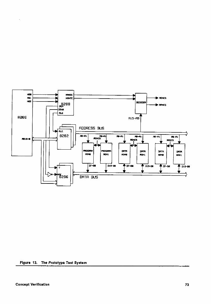
'°'ne"'”’°,8, —‘ mm
R moon,}:8,288 nmcsDTI!FLE
BQBS ms—ns
FIDDRESS BUS
8282 m-nn m-n ru-ax ru-ax m-an rs-mnm-o
I°‘°"‘$ nmcs mms
FRJGR1 PROGR1 um um um umR20 $11 H}0 @1 NI0 HM!
T U?-u U15-u Uhu ¤x5-u Uhu
286 DFITFI BUS
Figure 13. The Prototype Test System
Concept Verification 73
ther the functional or the gate level. The model of the 8086 microprocessor was
modified to facilitate the injection of SEUs into the microprocessor. The simulation
environment for this experiment is shown in Figure 14. A program written in C uses
a pseudo-random number generator to create the waveform files for successive
simulation runs. The simulation is controlled by a simulation control file that links the
stimuli provided by the waveform file to the prototype system and specifies the par-
ticular signals to be monitored during simulation. The system model file contains
information about the components used in the system and the circuit topology. The
individual components are in separate files that are linked together at simulation
time. External stimuli for the system are provided through a waveform file which also
includes information about injected faults. The simulation output is captured in a log
file. A translator program written in C is used to extract pertinent data from the log
file and put it in a format suitable for analysis. Quattro, a spread sheet program is
used for statistical analysis of data.
5.4.3 Test Program
An important consideration is the nature of the test software to be executed on the
processor during simulation. The choice of test program is influenced by the follow-
ing factors:
1. ldeally, a test program should check all possible instructions of a micro-
processor. However, there are practical considerations that limit this exercise.
For instance, the 8086 microprocessor has about 14,000 opcodes in its instruction
set. lt would require a very long time to test every instruction, let alone doing it
Concept Verification 74
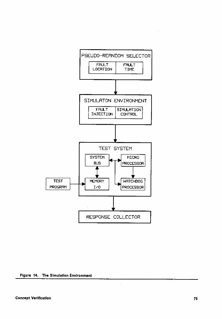
F’SEUDO—·REHNDOM SELECTOR
FFlULT FHULTLOCFITION TIME
”
SIMULBTON ENVIRONMENT
FRULT SIMULHTIONINJECTION CONTROL
SYSTEM MICROBUS PROCESSOR
TEST MEMORY NHTCHDOGPROGRFIM I/O PROCESSOR
RESPONSE COLLECTOR
Figure 14. The Slmulatlon Environment
Concept Verification 75
on a simulator which is several order of magnitude slower than the actual
processor.
2. Different types of instructions exercise different parts of a microprocessor and
some sections may be more sensitive than others. Therefore, the test program
must be so designed that it is similar to the programs that will run on the actual
system.
ln the light of the above arguments, a small test program was developed that exer-
cises a number of address and data manipulation operations that were chosen so as
to include at least one instruction from each instruction type described in the user
manual of the 8086 microprocessor [93]. The main program calls a subroutine that
computes the sum of an array stored in memory. The first item in the memory is the
length of the array. The sum is passes back to the main program which in turn counts
the the number of ones in the word representing the sum. This program exercises
memory read/write operations, stack operations, arithmetic and logic operations, and
subroutine calls. A listing of this test program is given in Appendix C. The output
of a typical run for fault-free and fault simulation cases are privided in Appendices D
and E respectively.
5.4.4 injected Fault Types
The type of fault to be injected in a simulation run is coded in the waveform file. A
C program generates the waveform file by using a pseudo-random number generator
to select the type, the time, and the place of the injected fault. injected faults are
chosen from a list of faults types shown in Table 2. A discussion about the fault types
shown in this table is given in section 3.4. The I,//, faults are not included in this list
Concept Verification 76
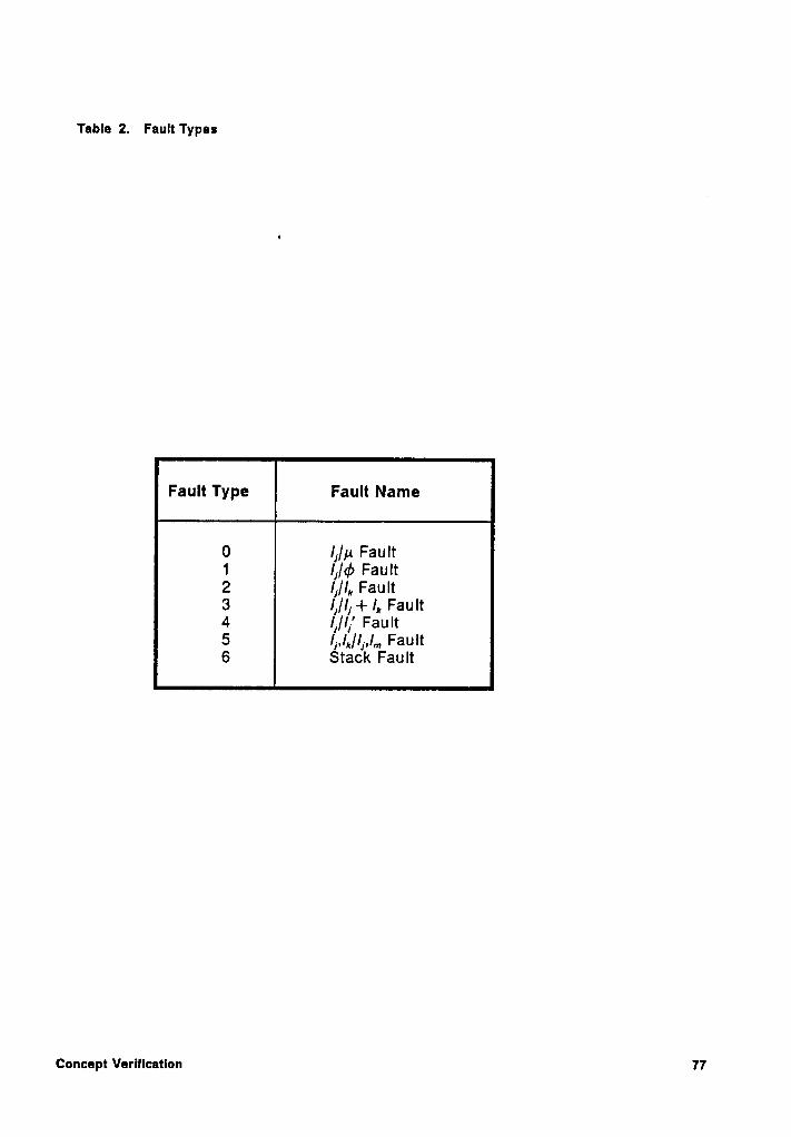
Table 2. Fault Types
0 lj//,4 Fault1 Ij/cb Fault2 Ij/I,. Faun3 /I//[ + l,, Fault4 lf/lf' Faun6 1,,1,/1„1,„ Faun6 Stack Fault
Concept Veriflcatlon 77
because they are a special case of the I,/I, faults and are, therefore, covered. Faultsh
are introduced so that they correspond to a change in the state of a bit in a register
or control signal for one Instruction cycle only. This change disappears when that
register is rewritten. Only one fault is injected during each simulation run. To obtain
statistically significant results, a large number of simulations are required.
Concept Verification 78
Chapter 6
Performance Evaluation
After the WDP implementation of the CPM scheme is designed, tested, and verified
to be operating correctly it must be shown to be effective in detecting transient faults.
This is done by defining performance criteria for measuring the detection scheme’s
effectiveness. ln this chapter, the metrics of performance evaluation are defined to
assess the effectiveness of the proposed scheme. The actual performance of the
CPM scheme is then determined.
6.1 Assessment Parameters
The primary requirement of a reliable system is that it should be able to tolerate
faults so that its output is always correct. Since this is not always possible, a small
error detection Iatency time is deslred so as to limit the damage and initiate efficient
recovery procedures with minimal performance penalty. In general, the reliability
and availability measures may be considered an adequate reflection of the perform-
ance of a system. These depend upon error detection Iatency and error coverage
Performance Evaluation T9
characteristics of a system. The longer a fault remains undetected, the more likely
lt is that it may cause more damage to the system. Once a fault is detected, an ap-
propriate recovery action must be taken to undo the damage, if any, and resume
normal operation. Hence, a small fault latency, a high fault coverage, and an efficient
recovery would be the most desirable characteristics of a fault tolerant system. In
addition to determining the probability that a fault is detected, the performance met-
rics should also measure the probability of a false alarm. A set of parameters satis-
fying these objectives would include the following [94,95]:
1. Probability that a fault is detected (fault coverage).
2. Probability that a fault is incorrectly indicated (false alarm).
3. Time to error detection (error detection latency).
4. Cost of reliability (overhead).
These parameters specify the most desirable characteristics of a reliable system.
The improvement in reliability of a system due to incorporation of fault tolerance
mechanisms must be balanced against the cost associated with these schemes. This
cost can be broadly divided into hardware costs, software costs, and the performance
penalty in terms of time and speed. The hardware cost mainly involves space, power,
and weight of the additional circuitry. The software cost, on the other hand, is
somewhat more difficult to assess. lt is affected at three levels; operating system
software, application software, and diagnostic software [94]. A first order estimate
of software cost may be made in terms of the extra memory space needed for diag-
nostic programs. The performance penalty consists of two components; performance
loss during normal operation and performance loss due to exception processing. The
performance loss during normal operation is due to the processing required to peri-
Performance Evaluation'
80
odically save the state of the system e.g., creating a check point or reading signa-
tures embedded in a program. lf an error is detected, the system must perform a
recovery operation such as restarting from the previous check point. This processing
of the exception also results in performance loss.
An important point that must be addressed is the way error detection latency time is
measured. The execution profile verification scheme detects faults following the
completion of an instruction. Thus, a fault that occurs during the execution of an in-
struction can be detected only after the instruction is completed i.e., error detection
Iatency is a function of the execution time of the instruction. This does not accurately
represent effectiveness of the detection scheme if the Iatency is measured in clock
cycles. Therefore, error detection Iatency is also measured in terms of instruction
execution cycles.
6.2 Analytical Results
Results describing the error coverage and error detection Iatency of the CPM scheme
can be calculated analytically for the execution profile of the instructions. Since the
execution profile parameters i.e., T(lj), B(/I), X(Ij), and S(I,), only monitor the instruction
execution and not necessarily cover other types of errors such as control flow errors,
stack errors, etc., these results give only a lower bound on the fault coverage. The
following analysis considers four mechanisms only, i.e., ETC, BCC, DTC and DSC.
Performance Evaluatlon 81
6.2.1 Error Coverage
The execution profile verification algorithm described earlier can detect all instruction
execution errors if the product of the partitions of the set I, i.e., 7I,7‘C,7Z§7'E, , has blocks
that contain at most one element. For many microprocessors this may not be the
case. For example, consider lntel’s 8086 microprocessor which has about 14,000
different types of instructions in its instruction set. The number of blocks in the
product 1:,1:,1:,1:, can be computed for the 8086 as follows. For a first order estimate,
instructions that have data dependent execution times may be neglected. For ex-
ample a move string instruction with a repeat prefix for the 8086 microprocessor has
an execution time which is a function of the data and cannot be predetermined. In
this analysis, such instructions are not included. Instructions not considered include
CMPS, DIV, IDIV, IMUL, MUL, MOVS, MOVSB, MOVSW, etc. The WDP design de-
scribed eariier does not cover these instructions. However, it can be incorporated in
the scheme by changing the architecture of DSC and DTC mechanisms. The re-
maining instructions can be divided into 46 different classes according to their exe-
cution times. Hence partition 1:, has 46 blocks. An 8086 instruction can be 1 to 6
bytes in length. Therefore, partition rc, has 6 blocks. During execution, an instruction
may perform 0, 1, or 2 memory transfers. These transfers correspond to no memory
operation, a read or write memory operation, or a read-modify-write memory opera-
tion for the 8086 microprocessor. Thus, partition 1:, has 3 blocks. The size of data
transferred can either be one or two bytes. Hence, partition 1:, has 2 blocks. There-
fore, the product 7I,7Z,1IiTZ, has 1656 blocks. Hence, on the average, there may be
14000/1656 = 8.45 instructions in a block. Instructions that are in the same block are
indistinguishable from each other.
Performance Evaluation 82
To determine error coverage, consider now the types of errors that may occur in a
radiation environment. Since SEUs are the primary source of transient faults, only
errors that produce a single bit change in the contents of a register/latch are con-
sidered. lt can be assumed that an instruction word can change to another instruc-
tion if, and only if, the two words are at a Hamming distance of 1 from each other.
Thus a 16-bit word may only change to one of 16 other words that are at a Hamming
distance of 1 from it. This is shown with the help of two examples.
Example 1:
Consider an opcode from the instruction set of InteI’s 8086 microprocessor.
ADD (BX)+(SI), |Ml\/l8
This is represented in machine code as 8000 (Hex). lt can change to 16 other words
which are listed in Table 3. Also included in the table are corresponding parameters
(X,T,B,S) of each instruction. Data in the table shows that some instructions gener-
ated by the fault can be distinguished from the original instruction. These are indi-
cated by an asterisk. Thus 13/16 = 81.25% of the errors can be detected using only
these parameters.
Example 2:
As another example, consider a single byte instruction that can change to eight other
possible opcodes:
PUSH ES
lts opcode in machine language is 06 (Hex). Its variants are shown in Table 4. Ex-
amining the differences in the execution profile parameters indicates that error cov-
erage is 87.5%. That is, this technique will detect 87.5% of the variants of this
instruction as an error. A similar calculation for a number of other instructions gave
an overall average fault coverage of about 85% for the 8086 instruction set.
Performance Evaluation 83
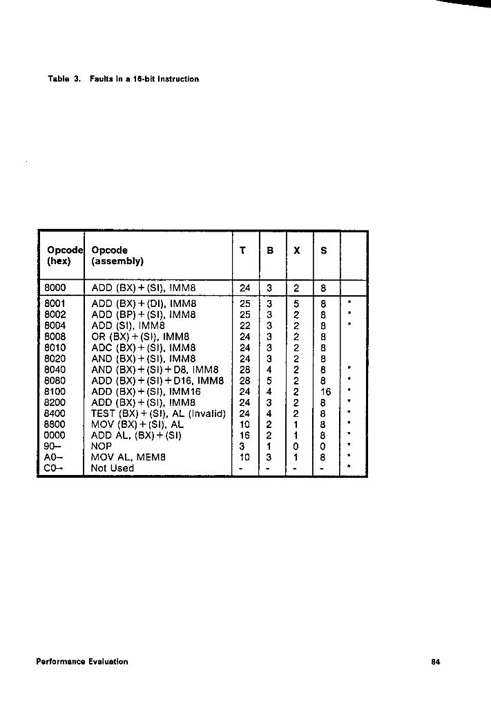
Table 3. Faults In a 16-bit Instruction
Opcode Opcode T(hex) (assembly)
6000 ADD (6x)+(s¤), IMM8 24 6 2 ¤-8001 ADD (BX)+(D|), IMM8 25 3 5 88002 ADD (BP)+(SI), IMM8 25 3 2 88004 ADD (SI), IMM8 22 3 2 88008 OR (BX)+(SI), IMM8 24 3 2 88010 ADC (BX)+(SI), IMM8 24 3 2 88020 AND (BX)+(SI), IMM8 24 3 2 88040 AND (BX)+(SI)+D8, IMM8 28 4 2 88080 ADD (BX)+(S|)+D16, IMM8 28 5 2 88100 ADD (BX)+(SI), IMM16 24 4 2 168200 ADD (BX)+(SI), IMM8 24 3 2 88400 TEST (BX)+(SI), AL (invalid) 24 4 2 88800 MOV (BX)+(SI), AL 10. 2 1 80000 ADD AL, (BX) + (SI) 16 2 1 890- NOP 3 1 0 0A0- MOV AL, MEM8 10 3 1 8CO-— Not Used -·--
Performance Evaluatlon 84
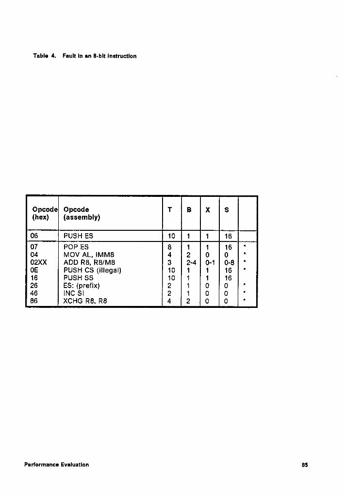
Table 4. Fault In an 8-bit Instruction
Opcode Opcode T(hex) (assembly)
Q PUSH ES E 1 1 1607 POP ES 8 1 1 1604 MOV AL, IMM8 4 2 0 002XX ADD R8, R8/M8 3 2-4 0-1 0-8OE PUSH CS (illegal) 10 1 1 1616 PUSH SS 10 1 1 1626 ES: (prefix) 2 1 O 046 INC SI 2 1 0 086 XCHG R8, R8 4 2 0 0
Performance Evaluation 85
6.2.2 Error Detection Latency
As explained earlier, the observed and expected parameters of an instruction are
_compared after the completion of an instruction. Any fault that occurs during the ex-
ecution of an instruction can be detected only after the instruction ls executed to
completion. Thus, this scheme, by design, detects errors as soon as the faulted in-
struction is completely executed. ln most cases, the error detection Iatency would
be less than two instruction cycles. Since some faults may produce control flow er-
rors, the next address detection scheme is used to detect any break in the normal
sequence of instructions. This can detect most errors as soon as the next instruction
is fetched for execution. The exception to this includes the case when during the
execution of a conditional jump instruction the control flag, that determines if the
jump should be taken, is perturbed. In this situation, no error is detected as long as
the program resumed at one of the two valid addresses. This can produce an inac-
curate result but there will not be a loss of control error.
Another situation where a control flow error may not be detected is when the jump
address has an offset which is stored in a data register. Here again, the WDP cannot
determine the destination address. The only option available is to verify that a jump
did indeed take place without verifying the destination address. Therefore, the aver-
age Iatency of next address detector depends upon the nature of the program and
may be slightly higher than 2 instruction cycles. To translate this observation to a
practical reaI·time environment, it would be necessary to determine the average
length of execution of all of the instructions used in the application software. A more
accurate measure would include a weighting factor to account for repeated use of
certain instructions.
Performance Evaluation 86
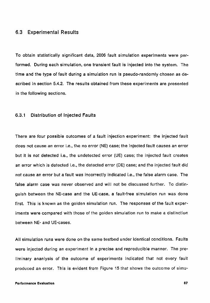
6.3 Experimental Results
To obtain statistically slgnificant data, 2006 fault simulation experiments were per-
formed. During each simulation, one transient fault is injected into the system. The
time and the type of fault during a simulation run is pseudo-randomly chosen as de-
scribed in section 5.4.2. The results obtained from these experiments are presented
in the following sections.
6.3.1 Distribution of injected Faults
There are four possible outcomes of a fault injection experiment: the injected fault
does not cause an error i.e., the no error (NE) case; the injected fault causes an error
but it is not detected i.e., the undetected error (UE) case; the injected fault creates
an error which is detected i.e., the detected error (DE) case; and the injected fault did
not cause an error but a fault was incorrectly indicated i.e., the false alarm case. The
false alarm case was never observed and will not be discussed further. To distin-
guish between the NE-case and the UE-case, a fault-free simulation run was done
first. This is known as the golden simulation run. The responses ofthe fault exper-
iments were compared with those of the golden simulation run to make a distinction
between NE- and UE-cases.
All simulation runs were done on the same testbed under identical conditions. Faults
were injected during an experiment in a precise and reproducible manner. The pre-
liminary ananlysis of the outcome of experiments indicated that not every fault
produced an error. This is evident from Figure 15 that shows the outcome of simu-
Performance Evaluation 87
NE • 722 (36%)
UE - EE <==··E>
DE • 1221
(61%)Flgure15. Simulatlon Results
Performance Evaluation 88
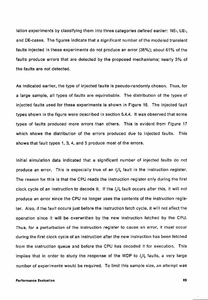
lation experiments by classifying them into three categories defined earlier: NE-, UE-,
and DE-cases. The figures indicate that a significant number ofthe modeled transient
faults injected in these experiments do not produce an error (36%); about 61% of the
faults produce errors that are detected by the proposed mechanisms; nearly 3% of
the faults are not detected.
As indicated earlier, the type of injected faults is pseudo—randomIy chosen. Thus, for
a large sample, all types of faults are equirobable. The distribution of the types of
injected faults used for these experiments is shown in Figure 16. The injected fault
types shown in the figure were described in section 5.4.4. lt was observed that some
types of faults produced more errors than others. This is evident from Figure 17
which shows the distribution of the errors produced due to injected faults. This
shows that fault types 1, 3, 4, and 5 produce most of the errors.
lnitial simulation data indicated that a significant number of injected faults do not
produce an error. This is especially true of an I,/I, fault in the instruction register.
The reason for this is that the CPU reads the instruction register only during the first
clock cycle of an instruction to decode it. If the li/l,, fault occurs after this, it will not
produce an error since the CPU no longer uses the contents of the instruction regis-
ter. Also, if the fault occurs just before the instruction fetch cycle, it will not affect the
operation since it will be overwritten by the new instruction fetched by the CPU.
Thus, for a perturbation of the instruction register to cause an error, it must occur
during the first clock cycle of an instruction after the new instruction has been fetched
from the instruction queue and before the CPU has decoded it for execution. This
implies that in order to study the response of the WDP to lj/l,„ faults, a very large
number of experiments would be required. To limit this sample size, an attempt was
Performance Evaluatlon 89
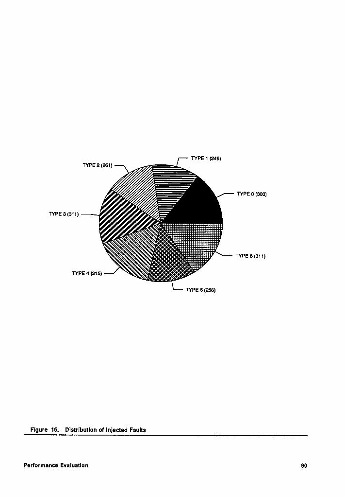
TYPE 1 (249)TYPE 2 (261) ——
ETYPE 0 (303)
Q7
—.\Q%€IE*EI§€EEEEEEEEEEEEEEEEEEEEEEEEEE?~ QQQ \~\
\‘\·—:j:•>Z:¢§:•ii5EEEEEEEEEEEEEEEEEEEEEE?*Q\§C \\\ $~ .\~§·i§?•€Z?•ij:•$°:l€EESEEEEEEEEEEEEEEEEF\\QQQQX\\
‘~Q ;_<•:_;•:_;¢_;•;j:•;‘;gggggg:::::::::::'
x \x \_ \ x •i T•) ei „•I C~; 16 it ••„„I:I:::III2'.‘\\g9;Y•;°p;’:•;°:e°;e?•;‘;¢:2:::::2:!:::' TYPE 6 (311)
‘~TYPE4 (315) —\\\\.'ä%°i•€°€é°E;?•E°EZ€:¥‘?:,‘¥?°“°
TYPE 5 (256)
Fi ure 16. Distribution of lnlected Faults9
Performance Evaluation 90
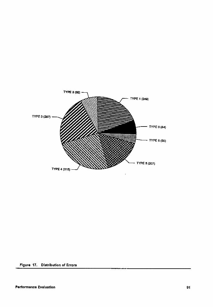
TYPE 2 (92) TYPE 1 (249)TYPE 3 (287)
TYPE 0 (84)Y?
Xx‘~
\X¤‘ Q. CQ\g•g,;•;•>§e>;•:§:•:§¢?e‘;6;t=r:::::::· TYPE 6 (50)X \ Q ··.\\ Q \\\ «¤X•:<•::¢:•::•::•:‘•~°«•^•~‘».~z—a~·X~\ \\\ _ \ \\ \ \\~ \\‘
Ö\C€é•Z•(•):Z•I:1€:9:g$•)Ü•;?•)Y•;?;¢°r· ‘ XQ ~ \
Q‘¤ \ X
. ~ :•;':•:‘e::•:?:°'•—°’?‘7é*?©—?\Q?iE\\ T\ TYPE 5 (207)
\~_TYPE4(315)"‘ \ ‘
Figure 17. Distribution of Errors
Performance Evaluation 91
made to ensure that an I,/I, fault is clocked into the instruction register before the CPU
attempts to decode it. This is achieved by injecting the faults in the instruction queue
of the processor instead of the instruction register. This will ensure that an /j/l,, fault
always produces an error. Also. this is why the number of errors produced due to
I}//,, faults, including both detected and undetected, seems disproportionately large.
6.3.2 Error Coverage _
A summary of the simulation experiments was shown in Figure 15. lnitially, a test
sample of 100 simulations were performed. Calculations for a 99 percent confidence
interval with allowable error of less than 2% indicated that a sample size of about
2000 is required. Hence, a total of 2006 fault experiments were conducted. Of these,
1284 or 64% produced errors; 1221 or 95.1% of the errors were detected by one or
more mechanisms; only 63 or 4.9% of the faults that produced errors were not de-
tected. Thus, the CPM scheme exhibits a high error coverage.
The distribution of detected errors for every fault type is shown in Table 5. The WDP
shows perfect error coverage for /J/qb, I], l,,/I], l,„ , and stack faults. A high coverage (in
the 99th percentile) is also achieved for I,/u and /I/I', faults. An overall fault coverage
of 96.8% is achieved for all faults. The reasons for relatively poor performance of the
detection scheme in case of I,//,, and /J/I, + l,, faults are investigated in Chapter 8.
The overall performance of individual mechanisms is shown in Figure 18. The num-
ber at the top of the bars indicates the percentage fault coverage provided by each
particular mechanism. As pointed out earlier, an injected fault can produce errors
that are detected by more than one detection mechanism. This is evident from Figure
Performance Evaluation 92
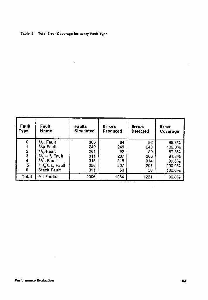
Table 5. Total Error Coverage for every Fault Type
Fault Faults Errors Errors ErrorType Slmulated Produced Detected Coverage
0 Ii/p Fault 303 84 82 99.3%1 Ii/¢ Fault 249 249 249 100.0%2 lf/I,„ Fault 261 92 59 87.3%3 lj//j + /,, Fault 311 287 260 91.3%4 lj/I'] Fault 315 315 314 99.6%5 /1, /,,/Ij, l„, Fault 256 207 207 100.0%6 Stack Fault 311 50 50 100.0%
Total All Faults 2006 1284 1221 96.8%
Performance Evaluation 93
18 where the sum of error coverage percentage of all mechanisms is more than
100%. An examination ofthese numbers also indicates that a large number of errors
are detected by just five mechanisms, namely ETC, BCC, IOC, NAC, and UMA. The
reasons why these five mechanisms perform so well are explored in Chapter 8. .
The performance of an individual mechanism against every type of fault is shown in
Table 6. Data in Table 6 also implies that a fault may be detected by more than one
mechanism. Since individual mechanisms have different error detection latencies,
the recovery procedure can be initiated by the mechanism that is first to detect the
error. Also, there is a good chance that a fault that escapes detection from one
mechanism is detected by another mechanism.
6.3.3 Error Detection Latency
Average error detection latency for all detection mechanisms in terms of clock cycles
and instruction cycles is shown in Figure 19 and Figure 20, respectively. The num-
bers at the top of each bar in Figure 20indicate the standard deviation for error de-
tection latency values of the individual mechanisms. As pointed out earlier, a better
sense of the effectiveness of the proposed error detection mechanisms can be ob-
tained by measuring the error latency in instruction cycles instead of clock cycles.
Therefore, in following discussion, the error detection latency is measured in in-
struction cycles only. The average error detection latency for all mechanisms is 1.47
instruction cycles. A low error detection latency value is useful because it limits the
propagation of an error.
Performance Evaluatlon”
94
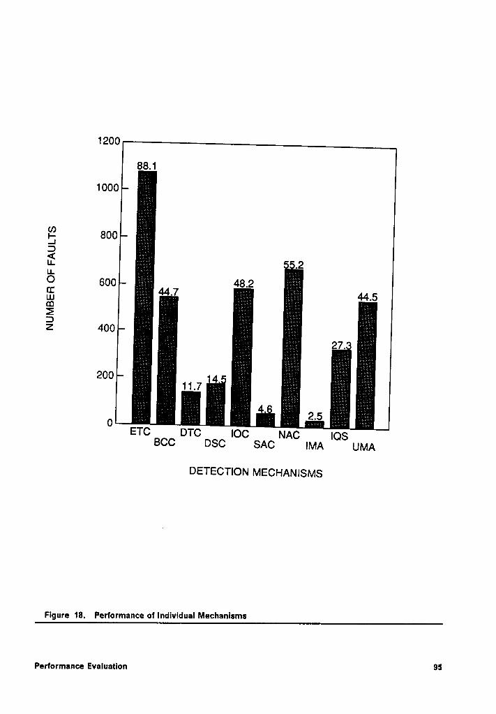
1200
88.1
1000_ÜÄ‘j_Q;”
gi·:18°°3
rgjjgjr-ff g3:S§gÄ€ÖjÄg1-1-39
600 48-2 §Si;g‘¥%=—;—·5:LI ‘£.;j2„;~jÄ—‘ 44.7é“2Z;;»j -i;3-;ħi¥Ä=§Eä 44.5LU ;';‘;§;§>';?_' ._ = -' ‘;i-:· 1; Ä-:_§·:„;,.¥ . .. 3Ä3I)
Äzj il S ·' z.:“Ä
1.- 5'jE’f”;Ä;Ä: ;I;r_g¥j2-‘_‘Z 400 3·000
J . ;;¢* 3Äa11-7O. _igzgjgigigfjjETCDTC IOC NAC IOSBCC DSC SAC IMA UMA
DETECTION MECHANISMS
Flgure 18. Performance of Individual Mechanlsms
Performance Evaluation 95
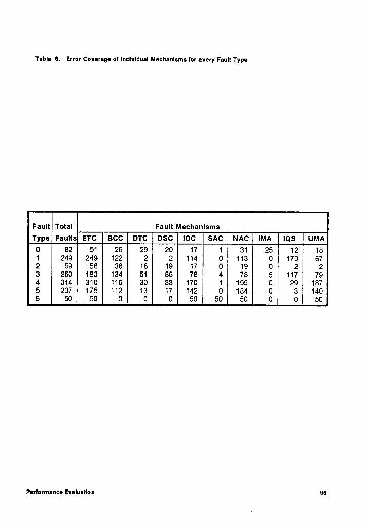
Table 6. Error Coverage of Individual Mechanlsms for every Fault Type
Fault Total Fault MechanismsType Feuue ETC acc DTC osc locsAc0
82 51 26 29 20 17 1 31 25 12 181 249 249 122 2 2 114 O 113 0 170 672 59 58 36 18 19 17 0 19 0 2 23 260 183 134 51 86 78 4 78 5 117 794 314 310 116 30 33 170 1 199 0 29 1875 207 175 112 13 17 142 0 184 0 3 1406 50 50 0 0 0 50 50 50 O 0 50
Performance Evaluation 96
The Iatency of each individual mechanism in terms of instruction cycles for every type
of fault, is shown in Table 7. This data shows that mechanisms ETC, IMA, IQS, and
UMA detect most of the errors in less than two instruction cycles. Almost all errors
are detected within three instruction cycles with the exception of stack faults. The
reason why stack faults are detected with much longer Iatency are explored in
Chapter 8.
6.4 Hardware Overhead of the CPM Scheme
ln order to estimate the hardware overhead for incorporating the CPM scheme in a
system, the WDP must be implemented in silicon. However, for the purpose of this
analysis, a first order measure of the complexity of the WDP can be obtained by es-
timating the area of the WDP chip. To estimate the area of the WDP chip, it is as-
sumed that most of the circuitry is implemented as PLAs. The structure of a PLA is
very regular and its area can be estimated easily.
The functional description of the WDP is given in Appendix A. A sizable portion ofthis
model is represented by ’case’ statements in the model. The size of the PLA im-
plementing this statement is determined as follows. First consider the structure of a
typical case statement construct. A case statement monitors a number of signals
included in its sensitivity list. A value in this sensitivity list is decoded to select one
of many blocks in the body of the case statement. Every block has one or more
statements called the action list. When implemented as a PLA, the number of signals
in the sensitivity list is the number of inputs to the PLA, the number of blocks in the
case statement are the number of product terms in the PLA, and the number of
Performance Evaluation 97
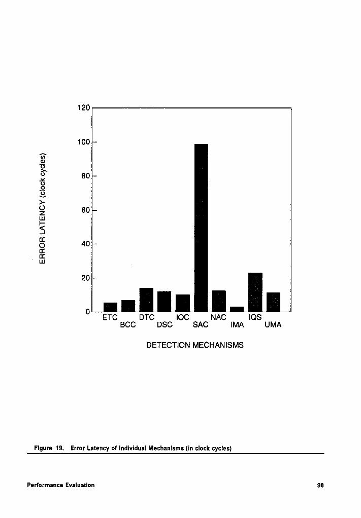
120
100
759O?>“
80*6985Z 60usI-5S 40CE
r ¤:ua
20
0ETC DTC IOC NAC IOS
BCC DSC SAC IMA UMA
DETECTION MECHANISMS
Flgure 19. Error Latency of Individual Mechanlsms (in clock cycles)
Performance Evaluatlon 98
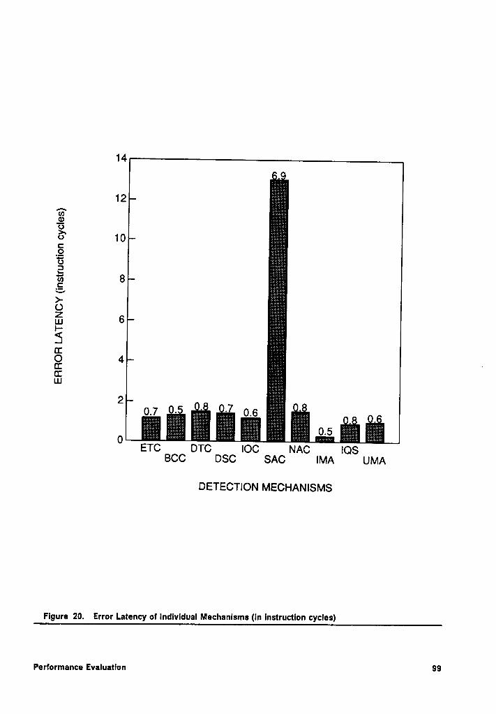
14
15;?;*¥§?:?::¥.EÜ
9.¤10C
;i;;;E;E=i;E§§¤E2 ;2;2;;s2;2;2;2;;*6E166E>-O
6"'Ü
4cc ·Cf ;f;*3?&E§I;LU0.7
- -7 0 6_._._..1 .•=_..._.ETC
DTC IOC NAC IOSBCC DSC SAC IMA UMA
DETECTION MECHANISMS
Flgure 20. Error Latency of Individual Mechanlsms (ln Instruction cycles)
Performance Evaluatlon 99
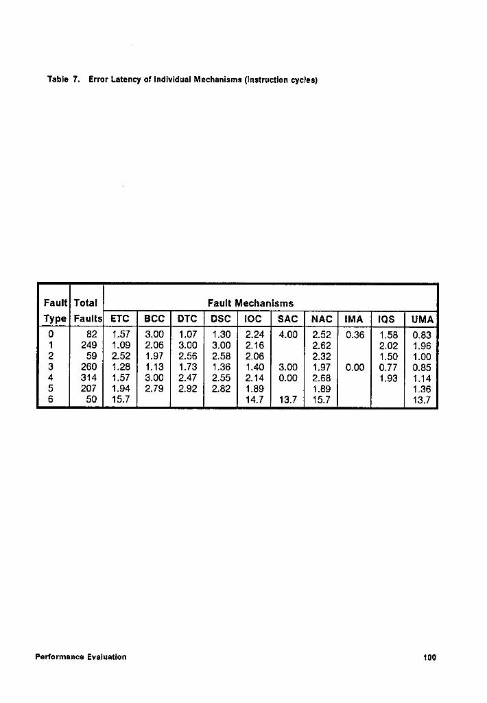
Table 7. Error Latency of lndlvldual Mechanisms (Instruction cycles)
Fault Total Fault MechanlsmsType Faults ETC acc DTC osc loc sAcNAc0
82 1.57 3.00 1.07 1.30 2.24 4.00 2.52 0.36 1.58 0.831 249 1.09 2.06 3.00 3.00 2.16 2.62 2.02 1.962 59 2.52 1.97 2.56 2.58 2.06 2.32 1.50 1.003 260 1.28 1.13 1.73 1.36 1.40 3.00 1.97 0.00 0.77 0.854 314 1.57 3.00 2.47 2.55 2.14 0.00 2.68 1.93 1.145 207 1.94 2.79 2.92 2.82 1.89 1.89 1.366 50 15.7 14.7 13.7 15.7 13.7
Performance Evaluatlon 100
unique signals generated in all action lists are the number of outputs of the PLA. The
area of an nMOS NOR~NOR PLA having i inputs, o outputs, and p, product terms is
given by the following equation [96]:
Area of PLA =(16i + 80 + 50) x (8p + 77),1*
The area of the instruction decoding logic of the WDP can be estimated by consider-
ing the case statement that is used to model it. There are 8 signals in the sensitivity
list of the case statement, 107 action blocks, and it generates 55 unique signals.
Thus, i= 8, p = 107, and o=55. The estimated area of the PLA implementing this
statement is calculated to be 576594,1*. A similar calculation is performed for all other
case statements in the model. The net area estimate for all PLAs implementing every
case statement in the WDP model is 983604,1*.
Besides the case statement, the WDP model also contains other constructs such as
if-then-else, storage elements, and when statements. For a rough estimate, the if-
then-else statement can be thought of as a case statement with i= 1 and p = 2. The
number of outputs is different for every statement. For these calculations, a mean
value of o =4 is assumed. Thus the area associated with the implementation of an
if-then—eIse statement is 9114,1*. As there are about 25 if-then-else statements in the
WDP model, the total area estimate for these statements is about 2278501*. The WDP
model employs a significant number of storage elements; 411 1-bit registers in all.
Assuming a 1-bit register to be 500,1* in area, the total silicon area used or all storage
elements is about 205500,1*.
Adding all the area estimates computed above, the total silicon surface required is
about 14169541*. Assuming a 50% overhead for control circuitry, routing and I/O
pads, the total WDP chip area is about 21254311*. lf implemented in 2 micron nMOS
Performance Evaluation 101
technology, the actual area of the WDP chip would be about 8501724 microrß. The
area of the 8086 microprocessor Is about 33387000 micronz (225 mil X 230 mil). Thus,
the WDP chip Is about 25% of the 8086 microprocessor In terms of silicon area. lt
must be pointed out that the above calculations are not only a rough estimate of the
area of the WDP chip and an accurate figure can be made by actually impiementing
the chip In silicon.
6.5 Reliability
The probability that a given system will perform its required function under specified
conditions for a specified period of time Is the reliability of the system. The reliability
of a system can be improved by using highly reliable components that form the
building blocks of the system. In fault tolerant systems, reliability of a system is also
improved by incorporating error detection and correction circuitry. This enhanced
reliability can be assesses by comparing the reliability of the system operating with
and without the fault tolerance mechanisms.
The Improvement in reliability of the prototype system provided by the CPM scheme
can be determined analytically. A simple error model has been assumed for this
analysis. The following assumptions have been made:
1. The system consists of an 8086 microprocessor, the necessary Interface logic,
data and program memory, and the WDP. However, faults are considered for the
8086 only.
2. All system components are assumed to have constant and independent failure
rates.
Performance Evaluation 102
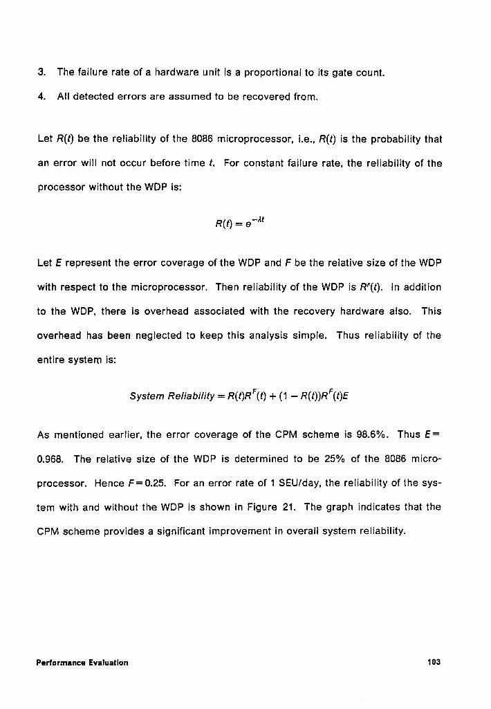
3. The failure rate of a hardware unit is a proportional to its gate count.
4. All detected errors are assu med to be recovered from.
Let R(t) be the reliability of the 8086 microprocessor, i.e., R(t) is the probability that
an error will not occur before time t. For constant failure rate, the reliability of the
processor without the WDP is: »
R(r) =6‘^'
Let E represent the error coverage of the WDP and F be the relative size of the WDP
with respect to the microprocessor. Then reliability of the WDP is R‘(t). In addition
to the WDP, there is overhead associated with the recovery hardware also. This
overhead has been neglected to keep this analysis simple. Thus reliability of the
entire system is:
System Re/iabi/ity = R(t)RF(t)+ (1 — R(t))RF(t)E
As mentioned earlier, the error coverage of the CPM scheme is 98.6%. Thus E=
0.968. The relative size of the WDP is determined to be 25% of the 8086 micro-
processor. Hence F=0.25. For an error rate of 1 SEU/day, the reliability of the sys-
tem with and without the WDP is shown in Figure 21. The graph indicates that the
CPM scheme provides a significant improvement in overall system reliability.
Performance Evaluation 103
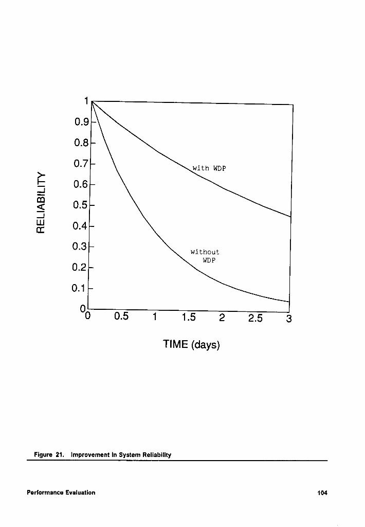
1
0.9
0.8
0.7
ä 0 6.
Q2 0.6..1g 0.4
0.3
0.2
0.1
00 0.5 1 1.5 2 2.5 3
TIME (days)
Figure 21. Improvement In System Rellability
Performance Evaluation 104
Chapter 7
Analysis of Results
The experimental results presented in Chapter 6 indicate that a significant number
of the 2006 injected faults do not produce an error (36%) in the 8086. This is ex-
plained by the fact that a transient fault, occurring in a section of the microprocessor
that is not currently being used, does not affect the execution ofthe Instruction. Since
a transient fault has no permanent effect, the faulted register performs properly when
used later. About 61% of the injected faults produced an error and were detected.
A small number of faults, which resulted In errors, were not detected (3.1%). Thus,
an overall error coverage of 96.8% was achieved. A detailed analysis of every type
of fault against every mechanism for error coverage and detection latency is pre-
sented in the following sections.
7.1 Error Coverage
The performance of individual transient fault detection mechanisms is shown in Fig-
ure 18 in Chapter 6. The number on top of each bar represents the percentage of
Analysis ol Results 105
errors detected by the corresponding mechanism. The figures indicate that a large
number of the errors are detected by only five mechanisms. These are: ETC (88.1%),
BCC (44.7%), IOC (48.2%), NAC (55.2%), and UMA (44.5%). Of these mechanisms,
ETC, BCC, and IOC are primarily directed at detecting execution errors while NAC
and UMA at control flow errors.
The data implicitly indicates that an error may be detected by more than one de·
tection mechanism. This is evident from the fact that the sum of the error coverage
percentages for individual mechanisms is more than 100%. As mentioned earlier,
this is because a transient fault can produce more than one type of error as its effect
propagates through the microprocessor’s circuits. Thus, the same fault may produce
many errors that can be detected by more than one mechanism. As such, different
mechanisms may have different error detection latencies for the same fault. This ef-
fect is evident from Figure 22 and Figure 23 which show multiple detection of an er-
ror by more than one mechanism. The latencies are measured in clock cycles and
instruction cycles in Figure 22 and Figure 23, respectively. The highest point onthebar
for each mechanism indicates the total error coverage and different portions
show the time of detection relative to others. The first area shows the number of
times that a particular mechanism was among the first to indicate the error, the sec-
ond area indicates the number of times it was among the second and so forth. During
the experiment, the responses were recorded for the first 50 clock cycles following
the detection of an error by any mechanism. The data was tabulated for the first three
detections only.
An analysis of undetected errors was performed to better understand why they were
not detected. For every type of fault, Table 8 shows the total number of faults simu~
Analysls of Results 106
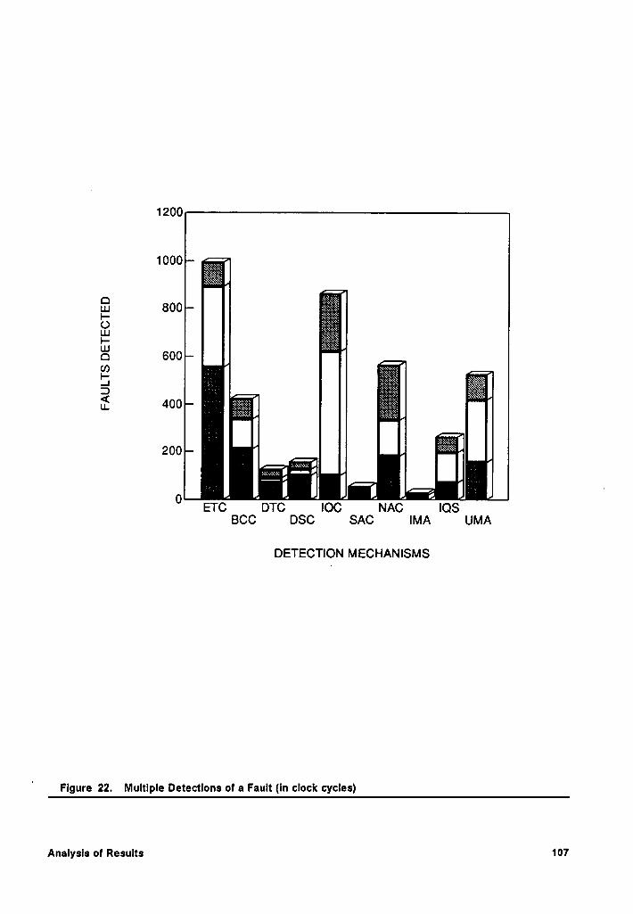
1200
E6000600 _
200 I—'
I I - ; ~0
E . . [ [ I I ‘ETC DTC IOC NAC IOSBCC DSC SAC IMA UMA
DETECTION MECHANISMS
Figure 22. Multiple Detectlons of a Fault (in clock cycles)
Analysis of Results 107
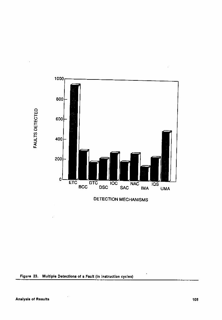
1000
800 I
QI.IJ ;·Lu 600P .UJQ éI- 400<IL ,200 |_ _
| 10ETC DTC IOC NACIOS
BCC DSC SAC IMA UMA
DETECTION MECHANISMS
Figure 23. Multiple Detectlons of a Fault (In Instruction cycles)'
Analysis of ResultsI
108
Iated, number of faults that resulted in errors, and the number and percentage of un-
detected faults. This data indicates that a significant number of type 2 and 3 faults
are not detected. These are I,/I, and I,/I, + I, faults. A detailed study of the simulation
results indicated that in many cases the fault produces a transition of the micro-
processor,from one valid state to another valid state. These two states are indistin-
guishable from each other. lt corresponds to some operation internal to the
microprocessor that does not produce any detectable change on the external lines.
Conceptually, this corresponds to the case when the two instructions, I, and /,, are in
the same block of the product 7l7,7IéTEéTC,. For example, the instructions for moving data
between memory and internal registers of the 8086 are encoded so that the internal
registers have addresses that differ by one bit only. Therefore, a change in an
opcode can result in the selection of an incorrect data register being used for an op-
eration. For many of these opcodes, the corresponding execution profiles are iden-
tical. Thus, a fault that produces a decoding error in selection of an internal data
register is not detected by the WDP.
A somewhat similar situation occurs for the I,/l,+ I, fault. lf the instructions I, and I,
have identical execution profiles, they cannot be distinguished from each other.
Since the WDP can neither determine the contents of internal data register nor can
it monitor the output of the register selection logic, it cannot detect a register de-
coding fault.
Another case of a undetected error is when a condltional jump instruction is exe-
cuted. lf the condition flag, that indicates if jump should be taken, is altered due to
a fault, an incorrect jump may be taken. The WDP cannot detect this since the only
information available to it is the jump address and the next sequential address. The
Analysis ar Results 109‘
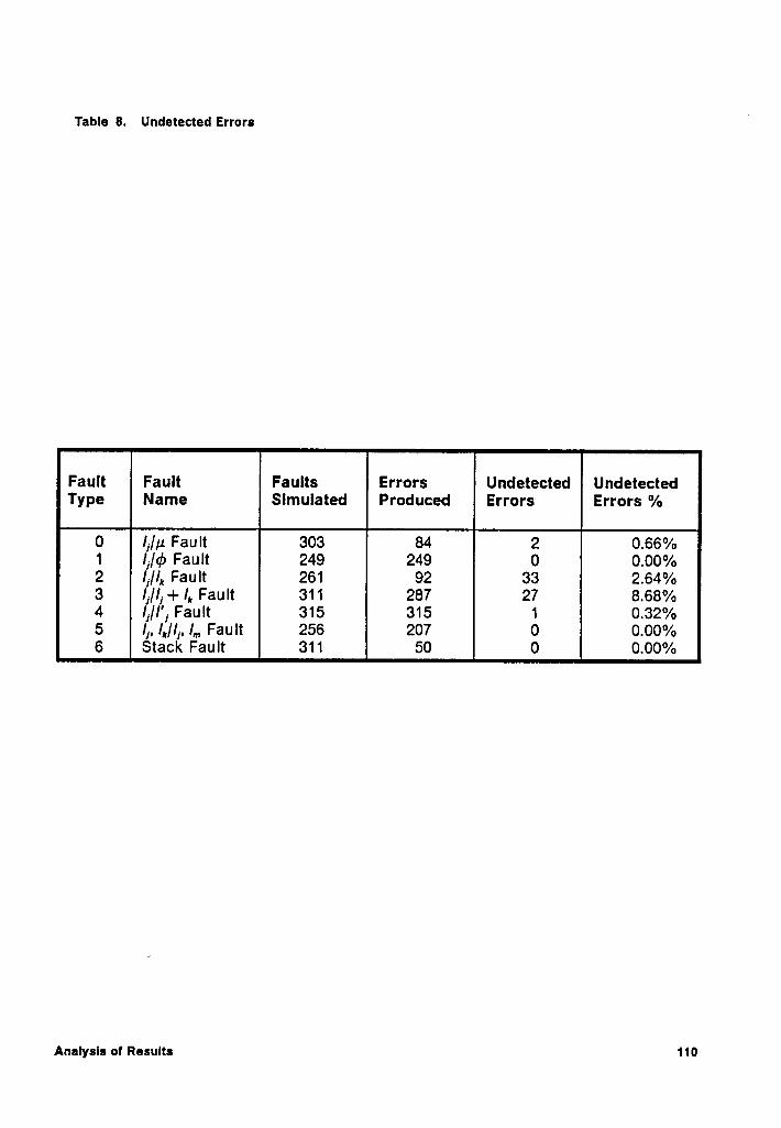
Table 8. Undetected Errorsl
Fault Faults Errors Undetected UndetectedType Slmulated Produced Errors Errors %
0 I,/p Fault 303 84 2 0.66%1 Ii/45 Fault 249 249 0 0.00%2 li/I, Fault 261 92 33 2.64%3 /j/I] + I, Fault 311 287 27 8.68%4 Ij/I'j Fault 315 315 1 0.32%5 I], /,/lj, l,„ Fault 256 207 O 0.00%6 Stack Fault 311 50 0 0.00%
Analysls of Results 110
WDP verifies that execution resumes at one ofthe two addresses. However, it cannot
check if the correct branch is taken.
A special case of an li/I, fault is when an opcode changes to F4 (hex). This is the
opcode for the HALT instruction for the 8086 microprocessor. Upon executing this
instruction, the microprocessor enters the halt state and no further action takes place.
In this situation, the WDP continues to wait for an instruction termination signal so
that it can detect if there were any errors. The result is an endless wait. A watchdog
timer may be used for detection of this condition.
7.2 Error Detection Latencyl
The average error detection latency of every mechanism was shown in Figure 19 and
Figure 20. For most mechanisms, the average error latency is small which is con-
sistent with the requirements of the WDP. A fault can produce errors that may be
detected by more than one mechanism. The individual mechanisms have different
error detection Iatencies. A better idea of overall error detection efficiency of the
WDP can be obtained by plotting the number of fault detections versus instruction
cycles. This is shown in Figure 24. The number at the top of each bar represents the
percentage of faults detected within a certain cycle. This graph points out that a
majority of error detections occur in the first few instruction cycles following the in-
cidence of a fault. Specifically, about 79.2% of all errors are detected in less than 2
instruction cycles. After the first few cycles, the error detection quickly declines to
zero. However, some faults are detected after a long time as indicated in the graph.
Analysis of Results 111
A close examination of the simulation results reveal that these are mostly stack
faults.
The value of the stack pointer is verified only when there is a stack operation per-
formed by the main processor. In the test program, stack Is used when the subrou-
tine is entered and exited. lf there is a stack fault after the subroutine has been
entered successfully, it will not be detected until the subroutine is exited because that
is when stack is used again. Thus, the structure of the software has a direct effect
on the error detection Iatency of a stack fault.
The error detection Iatency of each mechanism for every type of fault was shown in
Chapter 6. The instruction parameter monitoring mechanisms (ETC, BCC, DTC, and
DSC) detect errors following the completion of the current instruction. This implies
that the average error detection Iatency should be less than 2 instruction cycles.
However, the experimental evidence shows that the average Iatency values for ETC
and BCC are slightly higher than 2 instruction cycles. To explain this, consider an
/j/l,, fault. As mentioned earlier in section 6.3.1, this fault is injected by Introducing
errors in the instruction queue of the microprocessor and not its instruction register.
But the execution of the faulted instruction does not start until the preceding instruc-
tion is completed. Thus, the Iatency time of the faulted instruction partially includes
the execution time of the preceding instruction. Hence, simulation results give a
higher time than that the actual Iatency value. A similar argument can be made for
the IOC mechanism that detects li/I, faults because all I,/I, faults are subsets of I,//,,
faults.
All I,/lu faults that result in an illegal memory access are detected with very short
Iatency. This is because the IMA mechanism indicates an error as soon as it detects
Analysls of Results 112
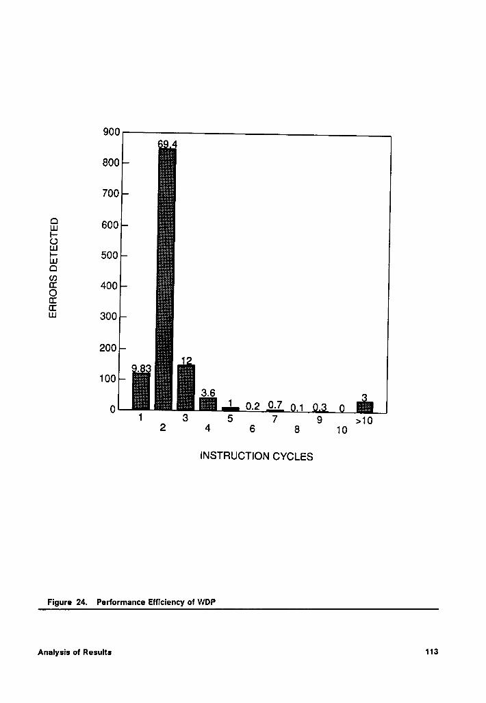
900
I-OE
500LU0Q
4000Q3Cc=¤
6000
é§;§é§ä;i§§;€;é 1 ()_2 0.7 1 g013 6 7 9 102 4 6 6 10
>
INSTRUCTION CYCLES
Figure 24. Performance Efficiency of WDP
Analysis of Results 113
it and does not wait for the end of an instruction. On the other hand, an lj/lt fault that
results in an access to an undefined memory location may have a significantly longer
Iatency. This is because an access to such a location fetches an invalid data value.
lf this is requested by the microprocessor for immediate use, the UMA mechanism
will check it for errors. But if this access was for normal prefetching of instructions,
it will be saved in the instructlon queue and will not be checked until it is fetched for
execution. Thus, in some cases, the error may have a long Iatency time. This ex-T
plains why the UMA mechanism has an average Iatency of 2.4 instructlon cycles.
Analysis of Results 114
Chapter 8
Conclusions
The frequency of occurrence of transient faults is much higher than that of permanent
faults in digital systems. This is especially true of space-borne systems that experi-
ence single event upsets due to the radiation environment in which they operate.
These upsets occur inside the processor and must be detected concurrently to allow
for real-time operation.
A new approach, called continuous processor monitoring scheme, aimed at concur-
rent detection of transient faults has been developed. lts effectiveness has been
demonstrated through computer simulations. A transient fault model is proposed that
defines the types of faults that may occur in an SEU environment. These include both
control flow as well as execution errors. For every opcode in the instruction set of a
processor, a set of observable parameters are defined that constitute its execution
profile. A watchdog processor concurrently monitors the execution profile of every
instruction and compares it with a previously determined execution profile to detect
any errors.
Conclusions115
8.1 Comparison of CPM With Other Schemes
l\/lost monitoring schemes proposed in the literature detect control flow errors during
the execution of a program by embedding signatures in the application program. This
affects the performance of the system because of following reasons:
1. The application program must be recompiled before it is executed on a system
that has the error detection hardware. The signatures are embedded in the pro-
gram during this compilation.
2. Additional memory is needed for storing the embedded signatures.
3. The performance of the main processor is degraded when signatures are fetched
from the memory.
Signatures of branch free intervals are computed during compilation and inserted at
appropriate places in the program. This means that software modifications are
needed before an application program can be executed on a system with the error
detection hardware. The proposed CPM scheme does not have this limitation be-
cause it does not require any changes in the software. In fact, it is completely
transparent to the rest of the system. Also, there is no memory overhead for the CPM
scheme because it does not require any signatures to be inserted in the program.
ln a signature monitoring system, the main processor executes a no operation (NOP)
instruction when a signature is fetched from the memory. This results in the loss of
performance as these clock cycles are wasted. This may not be a desirable situation,
especially in real-time systems. The CPM scheme does not suffer from this per-
formance loss as it does not need any embedded signatures.
Conclusions 116
A salient feature of signature monitoring schemes is that they verify the signatures
at the completion of a branch free interval. As discussed in Chapter 2, certain types
of errors can result in setting up of potentially endless loops that bypass the signa-
ture. These errors will not be detected by a signature monitoring scheme as the
section of code containing the signature is never executed. The CPM scheme, on the
other hand, verifies the instruction addresses at the beginning of the execution of
every instruction. Thus, there is a better chance that a CPM scheme will detect these
types of errors.
Most monitoring schemes using signature analyzers are aimed at detecting control
flow errors. But in an SEU environment, a processor can also experience execution
errors that must be detected. The CPM scheme is capable of detecting both control
flow and execution errors. In the CPM scheme, mechanisms aimed at verification of
execution profile of an instruction check for execution errors.
The proposed CPM scheme has been shown to be effective; both analytically and
experimentally. An overall transient fault coverage of 96.8% with an average error
detection Iatency of about 1.47 instruction cycles was achieved. This small error de-
tection Iatency is very important for initiating an efficient recovery procedure. ln most
cases, a simple instruction retry may be an effective recovery procedure.
The CPM scheme is superior if high coverage, low hardware overhead, low perform-
ance overhead, and low error Iatency dominate the system requirements. lts per-
formance is better that most schemes that use signature analyzers because those
schemes detect only control flow errors and have significant error Iatency. On the
other hand, a hardware redundancy scheme has better performance but suffers from
a high hardware overhead penalty.
Conclusions 117
The WDP for the CPM scheme is transparent to the rest of the system. This means
that it can be incorporated into existing systems without much changes in the hard-
ware. As mentioned earlier, the CPM scheme has no software component. This
suggests that existing application software can be run on a system using CPM
scheme with out any changes.
In the experiments reported here, the WDP circuitry was not subjected to transient
faults. For a complete analysis, the situation when a transient fault occurs in the WDP
must also be addressed. Such a fault may make WDP indicate an error when there
is none, i.e., false alarm. As the WDP is much smaller in area than the main
processor, it is less susceptible to an SEU. When it does experience an upset, and
consequently indicates a false alarm, a recovery procedure will be invoked. Thus the
only penalty ls the loss of performance of the system. However, this loss is expected
to be minimal because of the frequency of single event upsets; one per hour in the
worst case. Although a fully redundant or self checking WDP can be designed to
eliminate the possibility of false alarms, it is not very cost efficient as the penalty of
a false alarm is an occasional invocation of recovery procedures. Given the fre-
quency of SEUs, it may be a tolerable penalty in most systems.
8.2 Future Directions
A significant amount of hardware in the WDP is required to monitor the bus traffic and
extract the appropriate information for error detection. This overhead can be reduced
if the CPM monitor is implemented on the same chip as the microprocessor. In ad-
dition, the on chip detector will make internal signals of the microprocessor visible
Conclusions 118
to the WDP. This added observability means that those faults that go undetected
because certain internal control signals are not observable can be detected. As
mentioned in Chapter 6, these faults include errors in register decoding logic, control
flow errors due to change in the state of a condition flag, etc. For instance, consider
an I1/I, fault that changes the opcode of an instruction to that of another instruction.
As mentioned previously, the WDP cannot distinguish between the two instructions
if they have identical executlon profiles. This type of fault results in the selection of
an incorrect source or destination register for an operation. However, with access to
the internal signals, e.g., in this case the register selection logic, the WDP can note
the address generated by the register selection logic. The WDP can also determine
the correct address by partially decoding the instruction. By comparing the two reg-
ister addresses, the WDP can check if correct register was selected.
Another aspect to be considered is the time penalty for executing a recovery scheme.
To illustrate this, consider an ideal system that has a 100% fault coverage and a re-
covery procedure that is guaranteed to recover from every type of error condition.
The time penalty for the recovery is a function of how often the recovery procedure
is invoked and the executlon time of the recovery procedure. Even with an ideal
system, the processing of vital computations may get bogged down if the fault fre-
quency is very high. The use of rad hard components in building blocks ofthe system
can significantly reduce the frequency of occurrence of transient faults. Although
these rad hard components have a high tolerance to SEUs, they are not totally im-
mune to the types of faults discussed in this dissertation. Therefore, use of rad hard
components cannot completely eliminate the need for error detection schemes.
Concluslons119
Another factor to consider is the implementation of the recovery procedure. For
minimizing the performance loss due to an error, lt is necessary that the executlon
time of the recovery process be small. The scope of a recovery procedure ls a
function of the extent of damage due to an error. A fault tolerant system may have
a number of recovery procedure that may range from a simple instruction retry to a
complete restoration of the state of the processor. The selection of an appropriate
recovery procedure depends upon the information about the extent of damage due
to an error. Therefore, it important that the error detection mechanism not only notify
that an error has occurred but also provide some information about the extent of
damage. This information can then be used to invoke the most efficient recovery
procedure. Further work in development of error detection schemes should also try
to incorporate a damage assessment scheme.
Concluslons 120
Bibliography
1. D. A. Rennels, Fault-Tolerant Computing - Concepts and Examples, IEEE Trans-actions on Computers, Vol. C-33, No. 12, December 1984, pp. 1116-1129.
2. P. C. Carney, Selecting On-Board Satellite Computer Systems, Computer, Vol. 16,No. 4, April 1983, PP, 35-41.
3. D. A. Ballard, Designing Fail-safe Microprocessor Systems, Electronics, January4, 1979, PP. 139-143.
4. J. D. Blair and R. D. McCorkIe, Dual Digital Flight Control Redundancy Manage-ment System Development Program, Guidance and Control Conference, AIAA,1979, PD. 40-46.
5. W. E. Arens and D. A. Rennels, A Fault~ToIerant Computer for AutonomousSpacecraft, International Symposium on Fault·ToIerant Computing, 1983, pp.467-470.
6. R. D. Rasmussen and E. C. Litty, A Voyager Attitude Control Prospective on FaultTolerant Systems, Guidance and Control Conference, AIAA, 1981, pp. 241-248.
7. J. G. Yee and Y. H. Su, A Scheme for Tolerating Faulty Data in Real-Time Sys-tems, 2nd International Computer Software and Applications Conference, No-vember 1978, pp. 663-667.
8. T. Anderson and P. A. Lee, Fault Tolerance: Principles and Practice, Prentice HallInternational, Englewood Cllffs, NJ, 1981.
9. D. B. Sarrazin and M. Malek, Fault-Tolerant Semiconductor Memories, Computer,Vol. 17, No. 8, August 1984, pp. 49-56.
10. T. Anderson (Ed), Resilient Computing Systems, Vol. I, John Wiley 8, Sons, NY,1985.
11. P. K. Lala, Fault Tolerant and Fault Testable Hardware Design, Prentice-Hall Inc,Englewood Cliffs, New Jersey, 1985.
Bibliography 121
12. E. J. McCluskey, Hardware Fault Tolerance, Proceedings of the IEEE ComputerSociety International Conference (COMPCON), Feb 25-28, 1983, pp. 260-263.
13. D. Binder, E. G. Smith and A. B. Holman, Satellite Anomalies from Galactic Cos-mic Rays, IEEE Transaction s on Nuclear Science, Vol. NS-22, NO. 6, December1975, PP- 2675-2680.
14. M. Geilhufe, Soft Errors in Semiconductor Memories, IEEE Computer SocietyInternational Conference (COMCON 79), 1979, pp. 210-216.
15. J. C. Pickel and J. T. Blandford, Cosmic Ray lnduced Errors in MOS MemoryCells, IEEE Transactions on Nuclear Science, Vol. NS—25, No. 6, December 1978,pp. 1166-1170.
16. J. C. Pickel and J. T. Blandford, Cosmic Ray lnduced Errors in MOS Devices, IEEETransactions on Nuclear Science, Vol. NS-27, No. 2, April 1980, pp. 1006-1015.
17. J. C. Pickel and J. T. Blandford, CMOS RAM Cosmic Ray lnduced Error RateAnalysis, IEEE Transactions on Nuclear Science, Vol. NS-28, No. 6, December1981. PP- 3962-3967.
18. R. D. Rasmussen, Computing in the Presence ofSolt Bit Errors, American ControlConference, 1984, pp. 1125-1130.
19. J. F. Ziegler and W. A. Lanford, Effects of Cosmic Rays on Computer Memories,Science, Vol. 206, 16 November 1979, pp. 776-788.
20. T. C. May and M. H. Wood, Alpha·ParticIe-lnduced Soft Errors in Dynamic Mem-ories, IEEE Transactions on Electron Devices, Vol. ED·26, No. 1, January 1979, pp.2-9.
21. J. P. Woods, D. K. Nichols and W. E. Price, Investigation for Single·Event Upsetsin MSI Devices, IEEE Transactions on Nuclear Science, Vol. NS-28, No. 6, De-cember 1981, pp. 4022-4025.
22. D. K. Nichols, W. E. Price, C. J. Malone and L. S. Smith, A Summary ofJPL SingleEvent Upset Test Data from May 1982 through January 1984, IEEE Transactionson Nuclear Science, Vol. NS-31, No. 6, December 1984, pp. 1186-1192.
23. D. K. Nichols, W. E. Price amd C. J. Malone, Single Event Upset (SEU) of Semi-conductor Devices - A Summary of JPL Data, IEEE Transactions on Nuclear Sci-ence, Vol. NS-30, No. 6, December 1983, pp. 4520-4525. ·
24. W. A. Kolasinski, J. B. Blake, J. K. Anthony, W. E. Price and E. C. Smith, Simu-lation of Cosmic Ray lnduced Soft Errors and Latchup in Integrated Circuit Com-puter Memories, IEEE Transactions on Nuclear Science, Vol. NS-26, No. 6,December 1979, pp. 5087-5091.
25. R. Koga and W. A. Kolasinski, Heavy Ion-Induced Single Event Upsets of Micro-circuits: A Summary of' Aerospace Corporation Test Data, IEEE Transactions onNuclear Science, Vol. NS-31, No. 6, December 1984, pp. 1190-1195.
26. K. E. Martin, M. K. Gauthier, J. R. Cross, A. R. V. Dantas and W. E. Price, Total-Dose Radiation Effects Data for Semiconductor Devices: 1985 Supplement, JPL
Bibliography 122
Publication 85-43, Volume II, Parts A and B, Jet Propulsion Lab, California Insti-tute of Technology, Pasadena, CA, May 15, 1986.
27. S. E. Diehl, J. E. Vinson, B. D. Shafer and T. M. Mnich, Considerations for SingleEvent Immune VLSI Logic, IEEE Transactions on Nuclear Science, Vol. NS·30, No.6, December 1983, pp.4501-4507.
28. S. E. Diehl-Nagel, J. E. Vinson and E. L. Peterson, Single Event Upset Rate Pred-ictions for Complex Logic Systems, IEEE Transactions on Nuclear Science, Vol.NS-31, No. 6, December 1984, pp.1132-1138.
29. A. L. Friedman, B. Lawton, K. R. Hotelling, J. C. Pickel, V. H. Strahan and K. Loree,Single Event Upset in Combinational and Sequential Current Mode Logic, IEEETransactions on Nuclear Science, Vol. NS-32, No. 6, December 1985,pp.4216-4218.
30. D. P. Sieworek and R. S. Swarz, The Theory and Practice of Reliable System De-sign, Digital Press, Digital Equipment Corp., 1982.
31. D. P. Sieworek, Architecture of Fault-Tolerant Computers, Computer, Vol. 7, No.8, August 1984, pp. 9-18.
32. D. W. Haislett, A Methodology for Self Testing Microprocessors, Masters Thesis,Dept. of Electrical Engineering, Virginia Tech, Blacksburg, VA, 1982.
33. L. Chen and A. Avizienis, N·Version Programming: A Fault-Tolerant Approach toReliability of Software Operation, International Symposium on Fault-TolerantComputing, 1978, pp. 3-9.
34. J. C. Knight, N. G. Levenson and L. D. St. Jean, A Large Scale Experiment in N-version Programming, International Symposium on Fault-Tolerant Computing,1985, PP, 135-139.
35. A. Avizienis, Fault Tolerance by Means of External Monitoring of Computer Sys-tems, National Computer Conference, American Federation of Information Proc-essing Societies (AFIPS), Vol. 50, 1981, pp. 27-40.
36. T. S. Liu, The Role of a Maintenance Processor for a General-Purpose ComputerSystem, IEEE Transactions on Computers, Vol. C—33, No. 6, June 1984, pp. 507-517.
37. Rad-HardlHi-Rel Data Book, Harris Corporation, Melbourne, FL, 1987.
38. Y. Savaria, V. K. Agarwal, N. Rumin and J. F. Hayes, A design for Machines withBuilt-in Tolerance to Soft Errors, IEEE International Test Conference, 1984, pp.649-659.
39. X. Castillo, S. R. McConnel and D. P. Siewiorek, Derivation and Calibration of aTransient Error Reliability Model, IEEE Transactions on Computers, Vol. C-31, No.7, July 1982, PP- 658-671.
40. J. Sosnowski, Transient Fault Tolerance in Data Acquisition System, Microproc-essing and Microprogramming, Vol. 16, 1985, pp. 255-260.
41. J. Sosnowski, Transient Fault Effects in Microprocessor Controllers, ReliabilityTechnology - Theory & Applications (REL-CON, EUROPE 86), 1986, pp. 239-248.
Bibliography 123
42. R. G. Halse and C. Preece, Erroneous Execution and Recovery in MicroprocessorSystems, Software & Microsystems, Vol. 4, No. 3, June 1985, pp. 63-70.
43. M. O. Ahmad and D. V. Poornaiah, Design of a Logic Circuit for MicroprocessorRecovery From a Power Failure and a Transient Fault, IEEE Transactions on Cir-cuits and Systems, Vol. CAS-34, No. 4, April 1987, pp. 433-436.
44. R. E. Glaser and G. M. Masson, Transient Upsets in Microprocessor Controllers,International Symposium on Fault-Tolerant Computing, 1981, pp. 165-167.
45. R. E. Glaser and G. M. Masson, The Containment Set Approach to Crash-ProofMicroprocessor Controller Design, International Symposium on Fault-TolerantComputing, 1982. PP- 215-222.
46. R. E. Glaser and G. M. Masson, The Containment Set Approach to Upsets inDigital Systems, IEEE Transactions on Computers, Vol. C-31, No. 7, July 1982, pp.689-692.
47. M. E. Schmid, R. L. Trapp, A. E. Davidoff and G. M. Masson, Upset Exposure byMeans of Abstraction Verification, International Symposium on Fault-TolerantComputing, 1982, pp. 237-244.
48. K. W. Li, Detection of Transient Faults in Microprocessors by Means of ExternalHardware, Masters Thesis, Dept. of Electrical Engineering, Virginia Tech,Blacksburg, VA, 1984.
49. K. W. Li, J. R. Armstrong and J. G. Tront, An HDL Simulation of the Effects ofSingle Event Upsets on Microprocessor Program Flow, IEEE Transactions on Nu-clear Science, Vol. NS·31, No. 6, December 1984, pp.1139-1144.
50. S. F. Daniels, A Concurrent Test Technique for Standard Microprocessors, 26thIEEE Computer Society International Conference (COMCON), San Francisco, CA,February 28-March 3, 1983, pp.389-394.
51. J. V. Oak, J. G. Tront and J. R. Armstrong, A Block Checking Approach to SelfTesting Software, International Journal of Mini and Microcomputers, Vol. 7, No.3, 1985, PP. 83-88.
52. J. V. Oak, Block Checking Approach to Self·Testing Software, Masters Thesis,Dept. of Electrical Engineering, Virginia Tech, Blacksburg, VA, 1984.
53. E. K. Heironimus, Automated lncorporation of Upset Detection Mechanisms inDistributed Ada Systems, Masters Thesis, Dept. of Electrical Engineering, VirginiaTech, Blacksburg, VA, 1988.
54. H. Hecht, Fault-Tolerant Software for Real-Time Applications, ACM ComputingSurveys, Vol. 8, No. 4, December 1976, pp. 391-407.
55. B. Randell, System Structure for Software Fault Tolerance, IEEE Transaction onSoftware Engineering, Vol. SE-1, No. 2, June 1975, pp. 220-232.
56. N. G. Leveson and T. J. Shimeall, Safety Assertions for Process-Control Systems,International Symposium on FauIt·Tolerant Computing, 1983, pp. 236-240.
Bibliography 124
57. M. Namjoo and E. J. McCluskey, Watchdog Processors and Capability Checking,International Symposium on Fault-Tolerant Computing, 1982, pp. 245-248.
58. D. K. Bhavasar and R. W. Heckelman, Self Testing by Polynomial Division, IEEEInternational Test Conference, 1981, pp. 208-216.
59. K. S. Bhaskar, Signature Analysis: Yet Another Perspective, IEEE InternationalTest Conference, 1982, pp. 132-134.
60. J. P. Robinson and N. R. Saxena, A Unified View of Test Compression Methods,IEEE Transactions on Computers, Vol. C-36, No. 1, January 1987, pp. 94-99.
61. M. Namjoo, Techniques for Concurrent Testing of VLSI Processor Operation, IEEEInternational Test Conference, 1982, pp. 461-468.
62. T. Sridhar and S. M. Thatte, Concurrent Checking of Program Flow in VLSIProcessors, IEEE International Test Conference, 1982. PP- 191-199.
63. M. A. Schuette and J. P. Shen, Processor Control Flow Monitoring Using Signa-tured Instruction Streams, IEEE Transactions on Computers, Vol. C-36, No.3,March 1987, pp. 264-276.
64. K. D. Wilken and J. P. Shen, Embedded Signature Monitoring: Analysis andTechnique, IEEE International Test Conference, 1987, pp. 324-333.
65. A. Mahmood and E. J. McCluskey, Concurrent Error Detection Using WatchdogProcessors - A Survey, IEEE Transactions on Computers, Vol. C-37, No. 2, Febru-ary 1988, PP. 160-174.
66. A. Mahmood, D. J. Lu and E. J. McCluskey, Concurrent Fault Detection Using aWatchdog Processor and Assertions, IEEE International Test Conference, 1983,pp. 622-628.
67. A. Mahmood and E. J. McCluskey, Watchdog Processors: Error Coverage andOverhead, International Symposium on Fault-Tolerant Computing, 1985. PP.214-219.
68. A. Mahmood, A. Ersoz and E. J. McCluskey, Concurrent System Level Error De-tection Using a Watchdog Processor, IEEE International Test Conference, 1985,pp. 145- 152.
69. M. Namjoo, CERBERUS-16: An Architecture for a General Purpose WatchdogProcessor, CRC Technical Report No. 82-19, Center for Reliable Computing,Stanford University, December 1982.
70. J. P. Shen and M. A. Schuette, On-line Self-Monitoring Using Signatured Instruc-tion Streams, IEEE International Test Conference, 1983, pp. 275-282.
71. J. B. Elfert and J. P. Shen, Processor Monitoring using Asynchronous SignaturedInstruction Streams, IEEE International Test Conference, 1983, pp. 394-399.
72. K. D. Wilken and J. P. Shen, Continuous Signature Monitoring: Efficient Concur-rent Detection of Processor Control Errors, International Test Conference, 1988,pp. 914-925.
Blbllography 125
73. J. P. Hayes and E. J. McCluskey, Testability Considerations in Microprocessor-Based Design, Computer, March 1980, pp. 17-26.
74. C. H. Tung and J. P. Robinson, On Concurrently Testable MicroprogrammedControl Units, IEEE International Test Conference, 1986, pp. 895-900.
75. M. M. Yen, W. K. Fuchs and J. A. Abraham, Designing for Concurrent Error De-tection in VLSI: Application to a Microprogram Control Unit, IEEE Journal of SolidState Circuits, Vol. SC·22, No.4, August 1987, pp. 595-605.
76. V. S. Iyangar and L. L. Kinney, Concurrent Fault Detection in MicroprogrammedControl Units, IEEE Transactions on Computers, Vol. C-34, No. 9, September 1985,pp. 810-821.
77. A. M. Paschalis, C. Halatsis and G. Phllokyprou, Concurrently Totally Self-Checking Microprogrammed Control Units with Duplication of MicroprogramSequencer, Microprocessing and Microprogramming, Vol. 20, 1987, pp. 271-281.
78. J. Duran and T. Mangir, Application of Signature Analysis to the Concurrent Testof Microprogrammed Control Units, Microprocessing and Microprogramming,Vol. 20, 1987, pp. 309-322.
79. A. Anatola, R. Negrini, M. Sami and N. Scarabottolo, Transient Fault Managementin Microprogrammed Units: A Software Recovery Approach, EUROMICRO, 1985,pp. 453-461.
80. A. Anatola, R. Negrini, M. Sami and N. Scarabottolo, Hardening VLSI Micropro-grammed Units Against Transient Failures, Proc. VLSI and Computers, FirstInternational Conference on Computer Technology, Systems and Applications(COMPEURO), Hamberg, May 1987, pp. 8-10.
81. A. Anatola, I. Erenyi and N. Scarabottolo, Transient Fault Management in SystemsBased on the AMD 2900 Microprocessors, Microprocessing and Microprogram-ming, Vol. 20, 1987, pp. 205-217.
82. M. Marshal, Logic in Testingland - A Tale of Measurement Techniques, EDNMagazine, January 1976.
83. M. Marshal, Through the Memory Cells - Further Explorations of Integrated Cir-cuits in Testingland, EDN Magazine, February 1976.
84. M. Marshal, Microprocessors in Testingland - the Jury Receives its Instructions,EDN Magazine, March 1976.
85. K. K. Saluja, L. Shen and S. Y. H. Su, A Simplified Algorithm for Testing Micro-processors, IEEE International Test Conference, 1983, pp. 668-675.
86. S. M. Thatte and J. A. Abraham, Test Generation for Microprocessors, IEEETransactions on Computers, Vol. C-29, No. 6, June 1980, pp. 429-441.
87. W. Denhardt and V. M. Sorensen, Unspecified 8085 Opcodes Enhance Program-ming, Electronics, June 18, 1979, pp. 145-147.
88. J. Y. O. Fong, Microprocessor Modeling for Logic Simulation, IEEE InternationalTest Conference, 1981, pp. 458-460.
Bibliography 126
89. P. S. Bottoroff, Functional Testing Folklore and Fact, IEEE International TestConference, 1981, pp. 463-464.
90. J. A. Abraham, Functional Level Test Generation for Complex Digital Systems,IEEE International Test Conference, 1981, pp. 461-462.
91. HILO-3 Users Manual, Doc. #2522-0100, GenRad Inc., June 1985.
92. K. Mark and P. Measel, Total Dose Test Results for the 8086, IEEE Transactionson Nuclear Science, Vol. NS-29, No. 6, December 1982, pp. 70-80.
93. iAPX 86,88 Usefs Manual, Intel Corporation, Santa Clara, CA, July 1981.
94. J. B. Clany and R. A. Sacane, Sell’·Testing Computers, Computer, October, 1979,pp.49~59.
95. S. Osaki and T. Nishio, Reliability Evaluation of Some Fault-Tolerant ComputerArchitectures, Lecture Notes in Computer Science, Springr-Verlag, BerlinHeidelberg, West Germany, 1980.
96. D. S. Ha, On the Testable Design and Built-In Self-Test of PLAs, Ph. D. Disserta-tion, Dept. of Electrical and Computer Engineering, University of Iowa, Iowa, May1987.
Bibliography 127
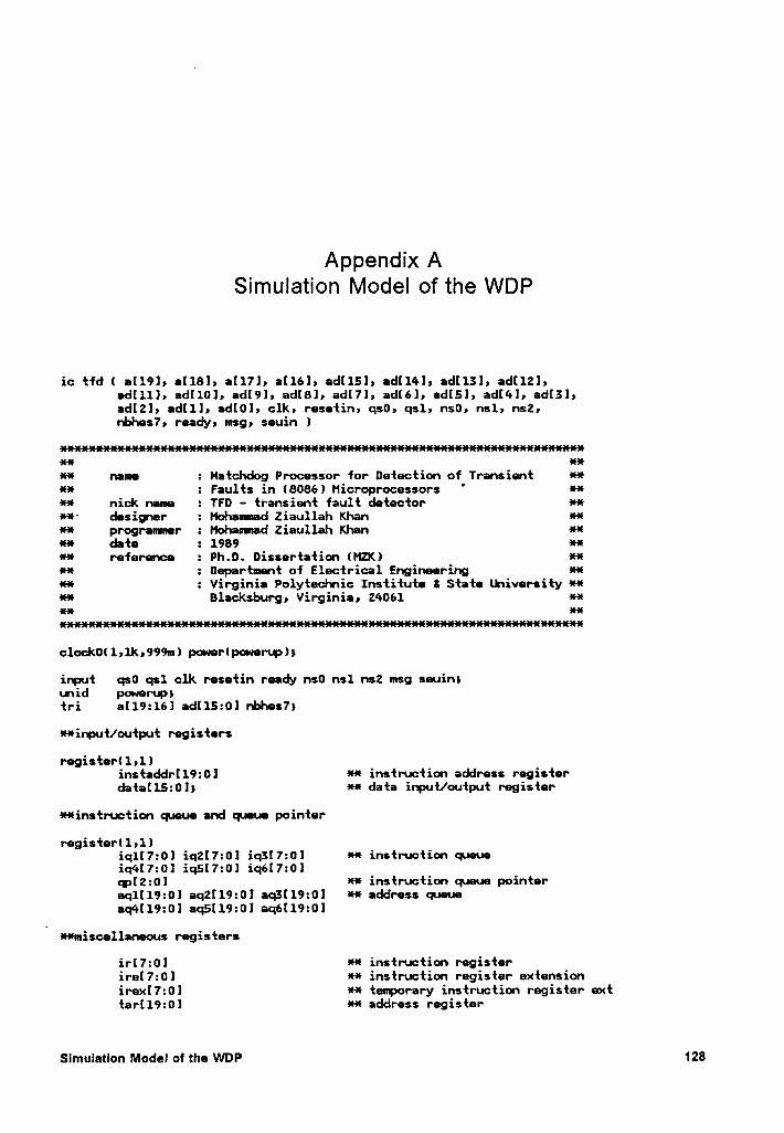
Appendix ASimulation Model of the WDP
ic tfd( a[191, aIl81, a[17l, a[16], d[151, adI14l, ad!131, ad[12l,edllll, ad!10], ad[9l, adI8], adl7], adl6], ad[5], ad[4], ad[3],ad[2], adlll, ad[0], clk, resetin, qs0, qsl, ns0, nsl, ns2,nbhes7, ready, msg, seuin )
as-zuusasausaus aus
** name : Natchdog Processor for Detection of Transient *4%
** : Faults in (8086) Hicroprocessors ' **** nick name : TFD - transient fault detector ****‘ desigxer : Mohauuad Ziaullah Khan *4%
** progranmer : Mohaunad Ziaullah Khan *4%4%* date : 1989 ***4% reference : Ph.D. Dissertation (MZO 4%*
** z Department of Electrical Engineering 4%*
** : Virginia Polyteclmic Institute 8 State University ***4% Blacksburg, Virginia, 24061 4%*asas asas
c1ock0(1,lk,999m) power(power•.„p)s
input qs0 qsl clk resetin ready ns0 ns1 ns2 msg seuins(mid powerup;tri al19:16] adll5:0] nbhes7$
**input/output registers
register(1,1)instaddrll9:0] ** instruction address registerdata[l5:0]s ** data input/output register
**instruction queue and queue pointer
register(l»l)iqll7:0] iq2l7:0l iq5l7:0] 4%* instruction queueiq4l7:0l iq5[7:0] iq6I7:0]qp[2:0l 4%* instruction queue pointeraql[l9:0] aq2[l9:0l aq3[l9:0l *4% address queueaq4[19:0l aq5Il9:0l aq6[19:0l
*4%misce1laneous registers
ir[7:0l 4%4% instruction registerirel7:0l ** instruction register extensionirex[7:0l **
tenporary instruction register exttar[l9:0] *4% address register
Slmulatlon Model of the WDP 128
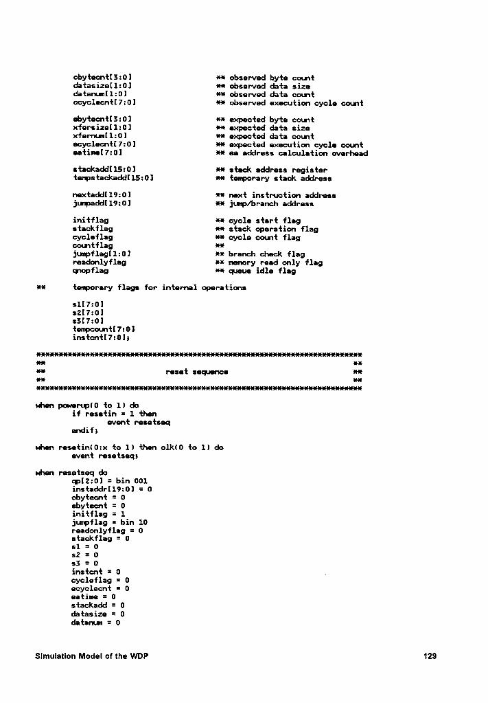
obytecnt[3:0] ff observed byte countdtasize[1:0] fü observed data sizedatanum[1:0l ff observed data countocyclecntI7:0] fü observed execution cycle count
ebytecnt[3:0] üf expected byte countxfersize[1:0] fü expected data sizexfernum[1:0] fü expected data countecyclecnt[7:0] fü expected execution cycle counteatime[7:0l ff ea address calculation overhead
stackaddI15:0] ff stack address registertempstackaddl15:0] fü tenporary stack address
nextadd[19:0l üf next instruction addressjumpadd[19:0] fü jump/branch address
initflag üü cycle start flagstackflag fü stack operation flagcycleflag fü cycle count flagcountflag ffjumpflag[1:0] fü branch check flagreadonlyfleg fü mmory read only flagqnopflag fü queue idle flag
üf temporary flags for internal operations
s1[7:0]s2[7:0ls3[7:0]tempcount[7:0linstcntl7:0l;
xx anüf reset sequence füxx ux
when powen4N0 to 1) doif resetin = 1 then
evnt resetseqendif)
whn resetin(0:x to 1) then clkl0 to 1) doevent resetseq;
when resetseq doqp[2:0l = bin 001instaddr[19:0] = 0obytecnt = 0ebytecnt = 0initflag = 1jumpflag = bin 10readonlyflag = 0stackflag = 0s1 = 0s2 = 0s3 = 0instcnt = 0 .cycleflag = 0ecyclecnt = 0eatime = 0stackadd = 0datasize = 0datanum = 0
Slmulatlon Model of the WDP 129
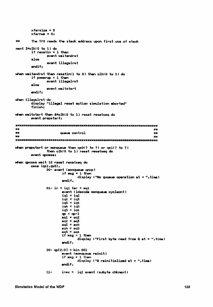
xfersize = 0xfernum = 0;
H The TFD reads the stack address upon first use of stack
next }*clkl0 to 1) doif rasetin = 1 then
event waitendrstelse
event illegalrstendif)
udnen waitendrst then resetinll to 0) then clk(0 to 1) doif powerup = 1 then
event illegalrstelse
event waitstartendif)
when illegalrst dodisplay "illegal reset action simulation aborted"finishx
when waitstart then 8*clk(0 to 1) reset resetseq doevent prepstart)
it! ge;H queua control eau
Hwhen prepstart or monqueue then qs0(? to 1) or qsll? to ?)then clkl0 to 1) reset resetseq do
event wasn
vhen wcase wait 10 reset resetseq docase {qs1,qs0},
00- event (monqueue qnop)if msg = 1 then
display 1"No quueue operation at = 'Utime)Bhdifa
01- ir = iq1 tar = aq1event lidecode monqueue cycleantliql = iq2iq2 = iq}iq} = iq¢•iq<• = iq5iq5 = iq6@ = @-1aql = aq2aq2 = aq}aq} =
aq¢•
aq4 = aq5aq5 = aq6if msg = 1 then
display I"First byte read from Q at = ",time)endif,
10- wI2:0] = bin 001event lmonqueue reinit)if msg = 1 then
display l"Q reinitialized at = ",timelBhdifs
11- irex = iql event (subyte chknext)
Slmulatlon Model 01 the WDP 130
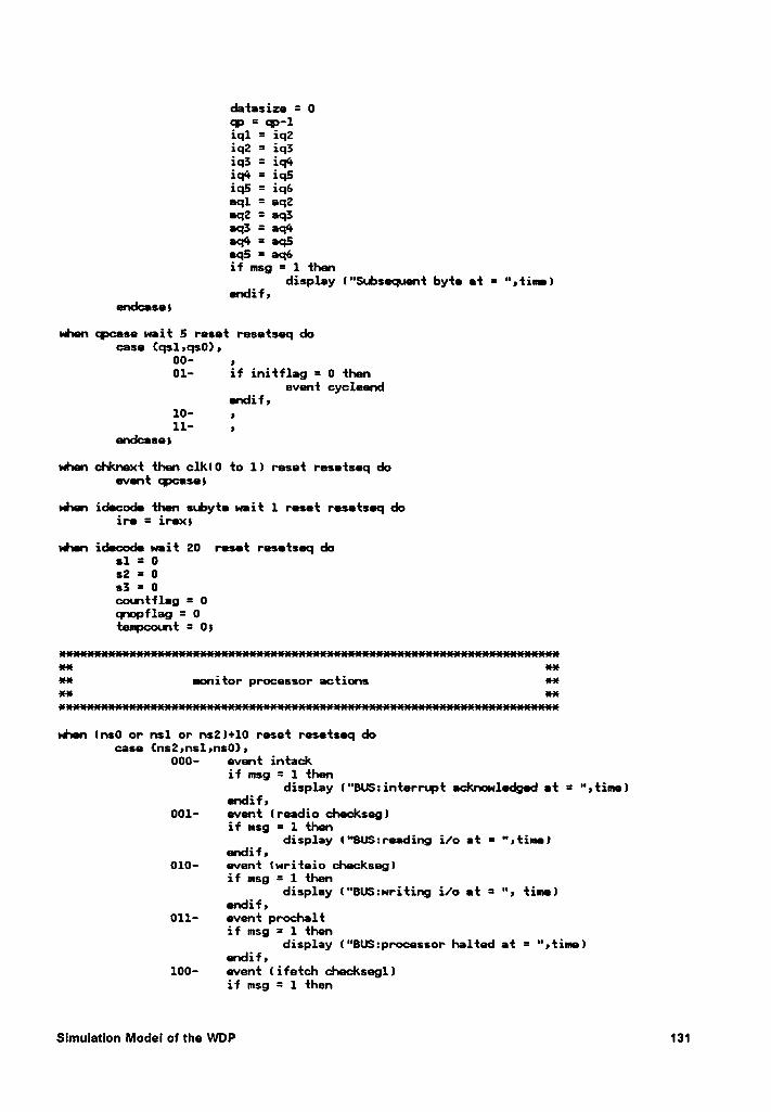
datasize = 09*
’ ‘*?'11.q1 = 1q2iq2 = iq}iq} =
iq<•iq¢•
= iq5iq5 = iq6aql = aq2eq2 = aq}aq} =
aq¢•
aq4 = eq5•q5= eq6
if msg = 1 thendisplay l"S«..bsequent byte et = ",tin•)
Üdifyendcase;
uhen cpcese wait 5 reset resetseq decase {qs1,qs0),
00- ,01- if initflag = 0 then
event cycleendÜidifs
1°- |
11- , ‘
endcesex
when chknext then clk(0 to 1) reset resetseq doevent epcaseß
vhen idecode then snbyte weit 1 reset resetseq doire = irex)
vhen idecode wait 20 reset resetseq dos1 = 0s2 = 0s} = 0conntfleg = 0cpopflag = 0tempcount = 0}
xxH monitor processor actions H·¤~¤· ·x·¤·
when (ns0 or nsl or ns2)+10 reset resetseq docase {ns2ms1ms0)»
000- event intackif msg = 1 then
display ("BU$:interr1.pt acknowledged et = ",time)endif,
001- event lreadio checkseglif msg = 1 then
display l°'BU$:re•ding i/o et = ",tim•lC’\dl";
010- event lwriteio checkseg)if msg = 1 then
display l"BU$:writing i/0 et =“,
time)Ondifs
011- event prochaltif msg = 1 then
display l"BU$:processor halted at = ",time)€1dl'f)
100- event lifetch checksegllif msg = 1 then
Slmulatlon Model of the WDP 131
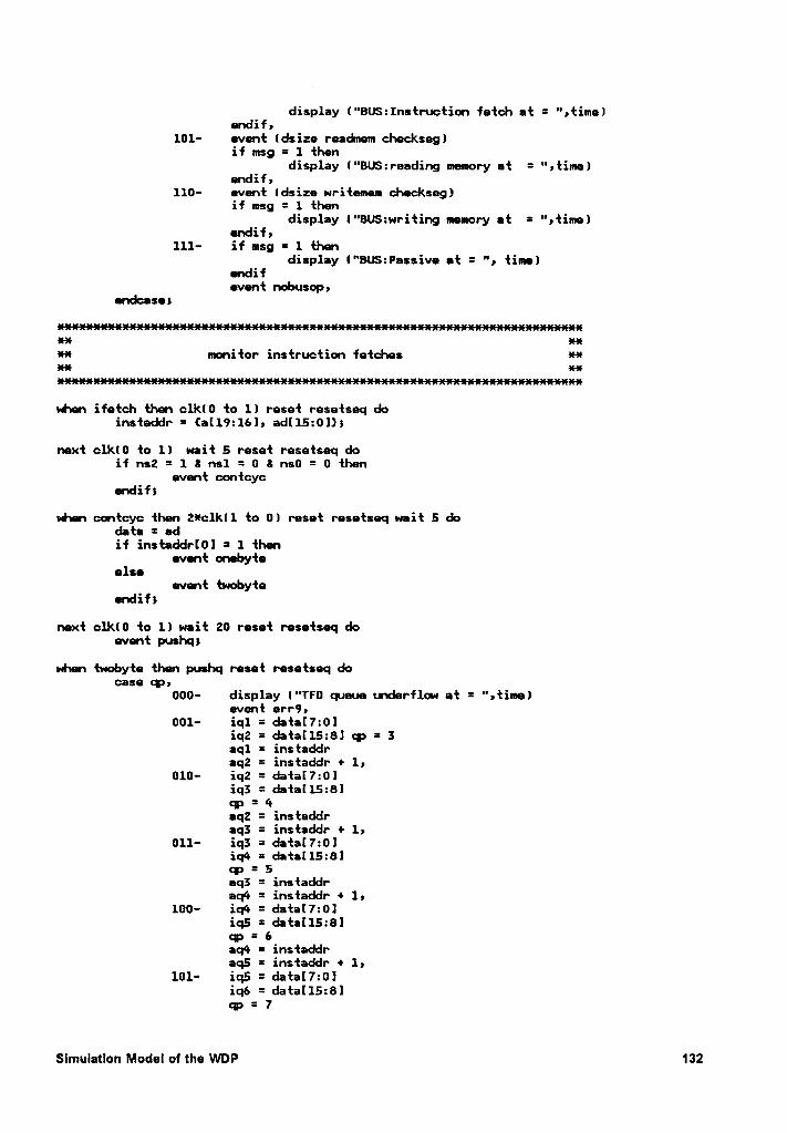
display ("BU$:Instruction fetch at = ",time)Qhdlfr
101- event (dsize readmem checkseg)if msg = 1 then
display ("BUS:reading memory et = ",time)Ondifr
110- event ldsize writeem checkseg)if msg = 1 then
display ("BU$:writing memory et = “,time)endif,
111- if msg = 1 thendisplay l"BUS:Pessive at = ", time)
endifevent nobusop,
endcase)
xxxxxxxxxxxxxxxxxxxxxxxxxxxxxxxxxxxxxxxxxxxxxxxxxxxxxxxxxxxxxxxxxxxxxxxxxxx xx
** monitor instruction fetches xxxx xxxxxxxxxxxxxxxxxxxxxxxxxxxxxxxxxxxxxxxxxxxxxxxxxxxxxxxxxxxxxxxxxxxxxxxxxxx
whn ifetch then clk(0 to 1) reset resetseq doinstaddr = (al19:16]) adl15:0]))
next c1k(0 to 1) weit 5 reset resetseq doif ns2 = 1 & ns1 = 0 & ns0 = 0 then
evnt contcycendif)
when contcyc then Zxclkll to 0) reset resetseq wait 5 dodata = adif instaddrl0l = 1 then
event onebyteelse
event twobytendif)
next clklü to 1) weit 20 reset resetseq doevent pushq)
whn twobyte then pushq reset resetseq do¢8$0 Cl):
000- display (“TFD queue underflow at = ",time)evnt err9)
001- iq1 = data[7:0]iq2 = data[15:81 qp = 3aql = instaddreq2 = instaddr + 1)
010- iq2 = data[7:0]iq3 = data[15:8]qp =
‘•eq2 = instaddraq3 = instaddr + 1,
011- iq3 = data[7:0liqü = data[15:8]cv = 5eq3 = instaddraqé = instaddr + 1,
100- iq4 = data[7:0liq5 = dta[15:8]q> = 6aq4 = instaddraq5 = instaddr + 1)
101- iq5 = data[7:0!iq6 = data[l5:8]cw = 7
Slmulatlen Model of the WDP 132
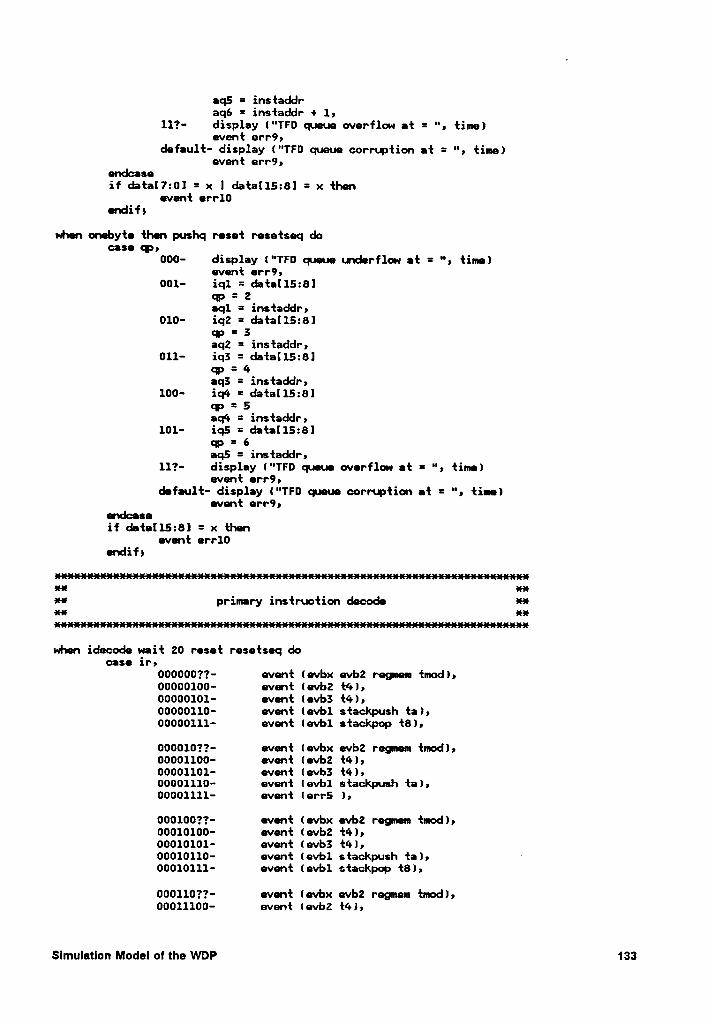
aq5 = insfaddraq6 = insfaddr + 1,
117- display l"TF0 queue overflow af =“,
fine)evenf err9,
defaulf- display l"TF0 queue corrupfion af =“,
fine)evenf err9,
endcaseif dafal7:0l = x I dafal15:B1 = x fhe
evenf err10ndif!
whn eneby{e {hen pushq resef resefseq doGISC 1a
000- display l"TF0 queue underflow ef = ", fine)evenf err9,
001- iql = da{aI15:8]<:> = 2aq1 = ins{addr,
010- iq2 = da{a(15:8lqp = 3aq2 = insfaddr,
011- iq! = da{a[15:8]qp = 4aq3 = insfaddr,
100- iq4 = d{a[15:8]<¤> = 5aq4 = insfaddr,
101- iq5 = da{al15:8lop = 6aq5 = insfaddr,
117- display l"TFD queue overflow ef = ", fine)evenf err9»
defaulf- display l“TF0 queue corrupfion ef = ", fine)evenf err9,
endcaseif dfa[15:81 = x {hen
evenf err10endif)
xx xx¤* primary insfrucfion decode xxxx xx
whn idecode uaif 20 resef resefseq docase ir,
00000077- evnf levbx evb2 regnen fnod),00000100- evnf {evb2 {4),00000101- evenf (evb3 {4),00000110- evnf levbl sfackpush fa),00000111- evenf levbl sfackpop {8),
00001077- evenf (evbx evb2 regnen {nod),00001100- evenf (evb2 {4),00001101- evn{ (evb3 {4),00001110- evenf levbl s{ackpush {a),00001111- evenf lerr5 ),
00010077- evenf (evbx evb2 regnen {mod),00010100- evenf (evb2 {4),00010101- evenf (evb3 {4),00010110- evenf levbl s{ackpush {al, ·00010111- evenf levbl sfackpop {8),
00011077- evnf levbx evb2 regnen fnod),00011100- evenf levbz {4),
Slmulatlon Model of the WDP 133
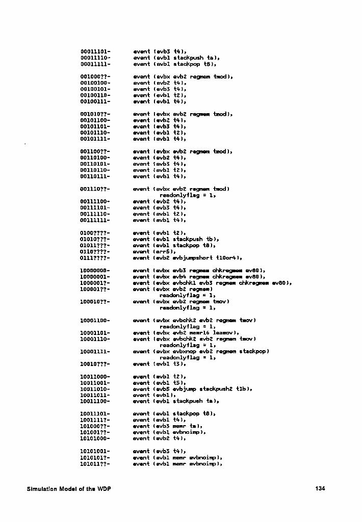
00011101- avant (avb3 {4),00011110- avnt lavbl stackpush ta),00011111- avnt lavbl stackpop {8),
001000??- avant lavbx avb2 ragmm {mod),00100100- avant (avb2 {4),00100101- avant (avb3 {4),00100110- avant lavbl {2),00100111- avant lavbl {4),
001010??- avnt Iavbx avb2 ragmam {mod),00101100- avant (avb2 {4),00101101- avnt (avb3 {4),00101110- avant lavbl {2),00101111- avant lavbl {4),
001100??— avant lavbx avb2 ragmun {mod),00110100- avant (avb2 {4),00110101- avnt lavbl {4),00110110- avant lavbl {2),00110111- avant lavbl {4),
0011l0??- avant (avbx avb2 ragmam {mod)raadonlyflag = 1,
00111100- avant (avb2 {4),00111101- avant (avb3 {4),00111110- avant lavbl {2),00111111- avant lavbl {4),
0100????· avant lavbl {2),010l0???· avat lavbl stackpush tb),01011???· avant lavbl stackpop {8),0110????· avant (arr5),0111????· avant (avb2 avbjumpshort t100r4),
10000000- avant lavbx avbl ragman chkragmam av80),10000001- avnt (avbx avb4 ragmm chkragmam av80),1000001?- avant (avbx avbchkl avbä ragmm chkragmam av80),100001??- avnt (avbx avb2 ragmam)
raadonlyflag = 1,100010??- avnt lavbx avb2 ragmam {mov)
raadonlyflag = 1,
10001100- avant lavbx avbchkz avb2 ragmam {mov)raadonlyflag = 1,
10001101- avant lavbx avb2 mamrl6 laamovl,10001110- avnt lavbx avbchk2 avb2 ragmam {mov)
raadonlyflag = 1,10001111- avant (avbx avbxnop avb2 ragmam stackpop)
raadonlyflag = 1,10010???· avant lavbl {3),
10011000- avant lavbl {2),10011001- avnt lavbl {5),10011010- avnt lavb5 avbjump stackpush2 {lb),10011011- avant lavbl ) ,10011100- avnt lavbl stackpush ta),
10011101- avant lavbl stackpop {8),l00111l?· avant lavbl {4),101000??— avant 1avb3 mamr ta),101001??- avant lavbl avbnoimp),10101000- avant lavb2 {4),
10101001- avant 1avb3 {4),
1010101?- avnt lavbl mamr avbnoimp),101011??- avant lavbl mmr avbnoimp),
Slmulation Modal ol tha WDP 134
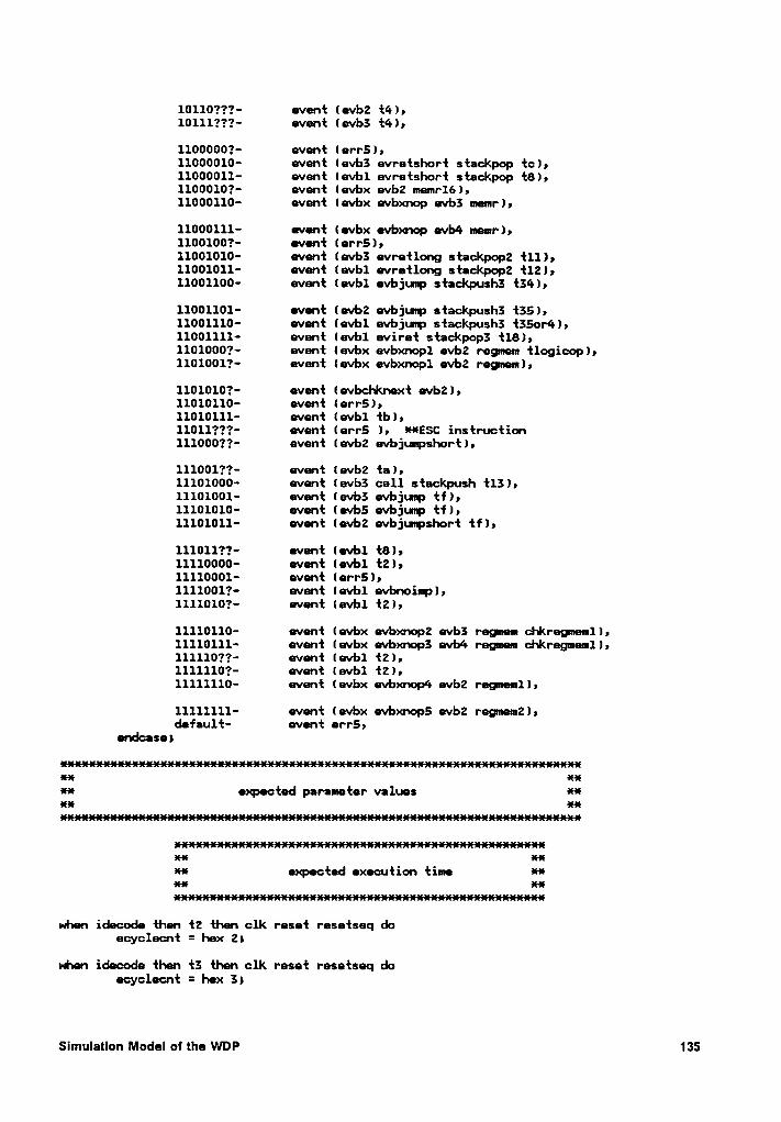
10110???- event (evb2 {4),101111*??· event (wb3 {4),
1100000?- event lerr5),11000010- event (evb3 evretshort stackpop te),11000011- event levbl evretshort stackpop {8),1100010?— event (evbx evb2 1nen1*16),11000110- event lwbx wbxnop wb3 nenr),
11000111- event (wbx wbxncp wb4 nenr),11001001*- went (err5),11001010- went (wb3 wretlong stackpop2 {11),11001011- went twbl wretlong stackpopz {12),11001100- went levbl evbjuvp stackpush3 {34),
11001101- went (evb2 wbjmp stackpush3 {35),11001110- went levbl evbjuzp stackpush3 {3501*4),11001111- event levbl eviret stackpop3 {18),11010001*- went (evbx evbxnopl evb2 regnen tlogieop),11010011*- event lwbx evbxnopl wb2 regnen),
1101010?- event (evbchknext wb2),11010110- event lerr5),11010111- went levbl tb),11011???- went (err5 ), *·¤·E$C instruction1110001‘?- event levb2 wbjunpshortl,
111001?1*- went 1wbZ ta),11101000- went lwb3 call stackpush {13),11101001- went lwb3 wbjuup tf),11101010- event (wb5 evbjmp tf),11101011- event lwb2 wbjupshort tf),
111011??- went tevbl {8),11110000- went (evb1 {2),11110001- event lerr5),11110011*- event levb1 evbnoinp),11110101*- went levb1 {2),
11110110- went levbx evbxnop2 wb3 regnen chkregnenll,11110111- event lwbx evbxnop3 wb4 regnen chkregnenll,11111071*- went levbl {2),1111110?- event levbl {2),11111110- went levbx wbxnopk wb2 regnenll,
11111111- went (evbx wbxnop5 wb2 reg1nen2),default- went err5,
endcasex
am·¤·-I expected parameter values Hxx xx
es-16 xxll-! expected exeeution time *·¤·xx xx
x·11··16ex»x«1ewhen
idecode then {2 then clk reset resetseq doecyclecnt = hex 2)
when idecode then {3 then clk reset resetseq doecyclecnt = hex 3)
Slmulatlon Model of the WDP 135
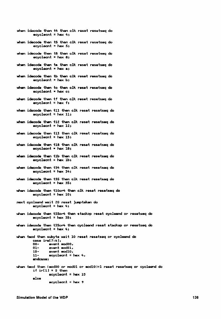
when idecode then {4 {lsen clk reset resetseq doecyclecnt = hex 4}
when idecode then {5 {hen clk reset resetseq doecyclecnt = hex 5}
when idecode {hen {8 {hen clk reset resetseq doecyclecnt = hex 8}
when idecode {lsen ta then clk reset resetseq doecyclecnt = hex a}
when idecode then tb {hen clk reset resetseq doecyclecnt = hex b}
when idecode {has tc then clk reset resetseq doecyclecnt = hex c}
when idecode then tf then clk reset resetseq doecyclecnt = hex f}
when idecode {hen {11 then clk reset resetseq doecyclecnt = hex 11}
when idecode then {12 then clk reset resetseq doecyclecnt = hex 12}
when idecode {hen {13 {hen clk reset resetseq doecyclecnt = hex 13}
when idecode {has {18 then clk reset resetseq deecyclecnt = hex 18}
when idecode tlsen {lb then clk reset resetseq doecyclecnt = hex 1b}
when idecode {has {34 {hen clk reset resetseq doecyclecnt = hex 34}
when idecode {has {35 {hen clk reset resetseq doecyclecnt = hex 35}
shen idecode then t10or4 {hen clk reset resetseq deecyclecnt = hex 10}
next cycleend wait 20 reset juuptaken doecyclecnt = hex 4}
whas idecode then t35or4 then stackop reset cycleend or resetseq deecyclecnt = hex 35}
when idecode {has {35or4 then cycleend reset stackop or resetseq doecyclecnt = hex 4}
when {mod {hen stbyte wait 10 reset resetseq or cycleend docase ire[7:6]}00- event mod00}01- event mod01}10- evast mod10}11- ecyclecnt = hex 4}endcase}
when {mod then lmod00 or mod01 or n•od10}+1 reset resetseq or cycleend doif ir[1] = 0 then
ecyclecnt = hex 10else
ecyclecnt = hex 9
Slmulatlon Model of the WDP 136
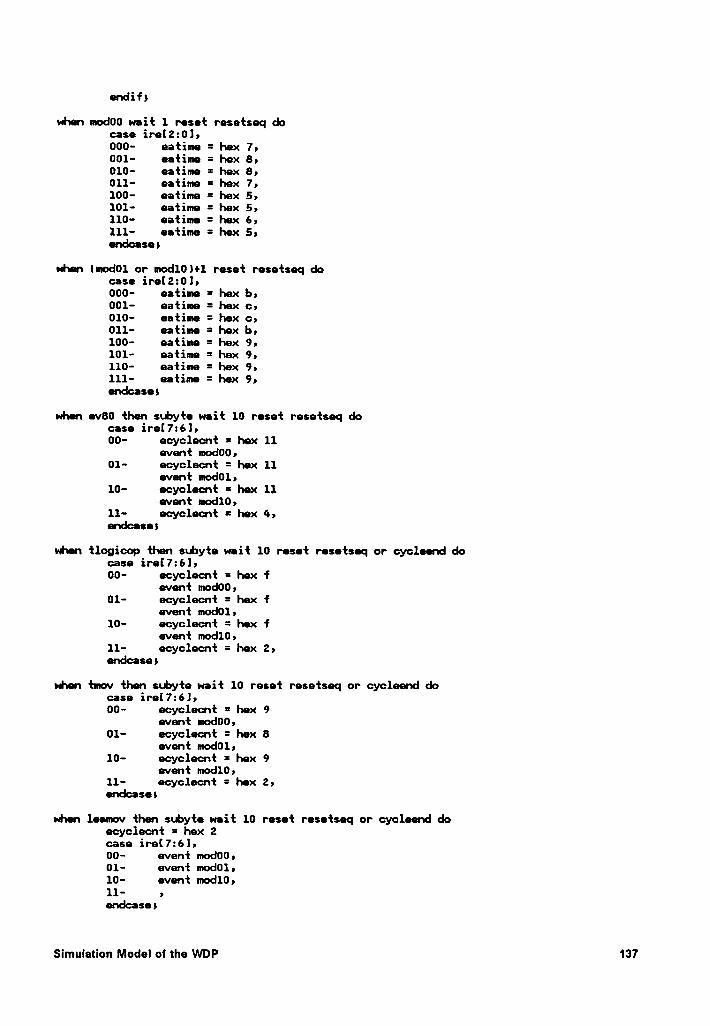
endif}
when mod00 wait 1 reset resetseq docase ire[2:0],000- eatime = hex 7,001- eatime = hex 8,010- eatime = hex 8,011- eatime = hex 7,100- eatime = hex 5,101- eatime = hex 5,110- eatine = hex 6,111- eatime = hex 5,endcesel
when l¤•od01 or mod10)+1 reset resetseq docase ire[2:01,000- eatime = hex b,001- eatime = hex c,010- eatime = hex c,011- eatime = hex b,100- eatime = hex 9,101- eatime = hex 9,110- eatime = hex 9,111- eatime = hex 9,endcasei
when ev80 then subyte wait 10 reset resetseq docase irel7:6l,00- ecyclecnt = hex 11
event mod00,01- ecyclecnt = hex 11
event mod01,10- ecyclecnt = hex 11
event ¤od10,11- ecyclecnt = hex 4,endcasei
when tlogicop then snbyte wait 10 reset resetseq or cycleend docase ireI7:6],00- ecyclecnt = hex f
event m¤d00,01- ecyclecnt = hex f
event mod01,10- ecyclecnt = hex f
event mod10,11- ecyclecnt = hex 2,endcase;
vhen tmev then snbyte wait 10 reset resetseq or cycleend docase ire[7:6],00- ecycleent = hex 9
event mod00,01- ecyclecnt = hex 8
event •nod01,10- ecyclecnt = hex 9
event mod10,11- ecyclecnt = hex Z,endcasei
when leamcv then snbyte wait 10 reset resetseq or cycleend doecyclecnt = hex 2case ire[7:6l,00- event m¤d00,01- event m¤d01,10- event mod10,11- ,endcase;
Slmulation Model o1 the WDP 137
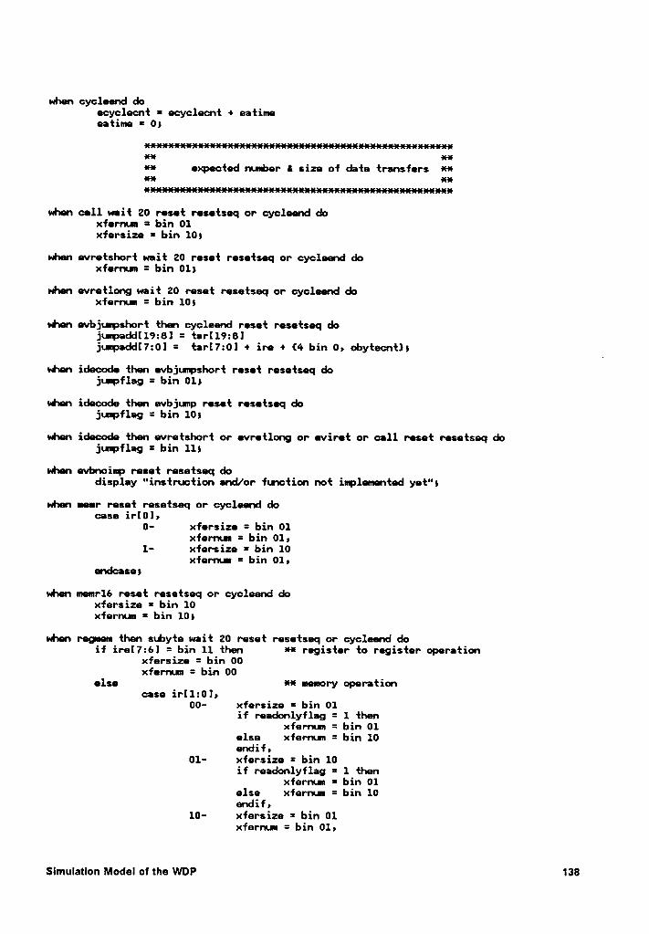
when cycleend doecyclecnt = ecyclecnt + eatimeeatime = 0;
4%* xx
** expected nuvber I size of data transfers *4%
** xx
when all wait 20 reset resetseq or cycleend doxfernun = bin 01xfersize = bin 101
vhen evretshort wait 20 reset resetseq or cycleend doxfernun = bin O1!
when evretlong wait 20 reset resetseq or cycleend doxfernun = bin 10$
when evbjurpshort then cycleend reset resetseq dojunpadd[19:8l = tar[l9:8lj•..mpadd[7:0l = tar[7:01 + ire + {4 bin 0, obytecnt)1
when idecode then evbjurpshort reset resetseq dojuspflag = bin 014
when idecode then evbjunp reset resetseq dojunpflag = bin 10;
when idecode then evretshort or evretlong or eviret or all reset resetseq dojuvpflag = bin 111
when evbnoinp reset resetseq dodisplay "instruction and/or fusction not iuplemented yet"s
when menr reset resetseq or cycleend docase ir[01,
0- xfersize = bin 01xfernun = bin 01,
1- xfersize = bin 10xfermm = bin 01,
endcase;
when memrlé reset resetseq or cycleend doxfersize = bin 10xfernuu = bin 10;
when regnen: then subyte wait 20 reset resetseq or cycleend doif ire[7:6] = bin 11 then ** register to register operation
xfersize = bin 00xfernun = bin 00
else *4% memory operationcase ir[1:0]»
00- xfersize = bin 01if readonlyflag = 1 then
xfernun = bin 01else xfernun = bin 10endif,
01- xfersize = bin 10if readonlyflag = 1 then
xfernum = bin 01else xfernum = bin 10endif,
10- xfersize = bin 01xferruu = bin 01,
Slmulatlon Model of the WDP 138
11- xfersize = bin 10xfernum = bin 01,
endcasereadonlyflag = 0
endif}
vdnen regneml then subyte wait 20 reset resetseq or cycleend doif ire[7:6] = bin 11 then
xfersize = bin 00xfernun = bin 00
else xfersize = bin 01xfernun = bin 10
endif}
when regnen2 then subyte wait 20 reset resetseq or cycleend doif ire[7:6l = bin 11 then
xfersize = bin 00xfernum = bin 00
else case irel5:3],00?- xfersize = bin 10
xfernun = bin 10,default- xfersize = bin 10
xfermn = bin 01,endcase
endif}
when chkregmen then subyte wait 10 reset resetseq or cycleend doif ireI5:3] = bin 111 then
readonlyflag = 1endif}
vdnen cHtregmem1 then snbyte wait 10 reset resetseq or cycleend docase ire[5:3l,
000- readonlyflag = 1,001- event err5,1??- readonlyflag = 1
event evbnoinp,p
endcase}
xx xxInt expected nurber ef instruction bytes Hae-! am
when evbl wait 20 reset resetseq doebytecnt = bin 0001}
when evb2 wait 20 reset resetseq doebytecnt = bin 0010}
vdnen evb3 wait 20 reset resetseq deebytecnt = bin 0011}
vdnen •vb4 wait 20 reset resetseq doebytecnt = bin 0100}
when evb5 wait 20 reset resetseq doebytecnt = bin 0101}
when evbx then subyte wait 20 reset resetseq or cycleend docase ire[7:01,
00???110- ebytecnt = ebytecnt • bin 0010,01??????· ebytecnt = ebytecnt + bin 0001,10??????· ebytecnt = ebytecnt + bin 0001,
endcase}
Slmulatlon Model of the WDP 139
whn evbchkl thn subyte wait 20 reset resetseq er cycleend douse ire[5:5l,
001- evnt err5,100- event err5»110- evnt err5»default- ,
endcasel
when evbchk2 then subyte wait 20 reset resetseq or cycleend douse ire[5]•
1- event err5•default- ,
endcasei
when evbxnop then subyte wait 20 reset resetseq or cyclend docase ire[5:3l,
000- ,default- event err5•
endcasel
when evbxnopl then subyte wait 20 reset resetseq or cycleend docase ire[5:3]»
110- evnt err5¤default- »
endcases
whn evbchknext then subyte wait 20 reset resetseq or cyclend docase irel7:0],
00001010- •default- event err5,
ndcase;
when evbxnopz then subyte wait 20 reset resetseq or cyclend docase ire[5:3]•
000- event evb3,001- evnt err5,default- event evb2,
endcase;
when evbxnopä then subyte wait 20 reset resetseq or cyclend docase irel5:3l»
000- event evb4»001- event err5,default- event evb2,
endcasel
when evbxnopß the subyte wait 20 reset resetseq or cycleend docase ireI5:3l»
00?- »default- event err5,
endcaseß
when evbxnop5 thn subyte wait 20 reset resetseq or cyclend docase ireI5:3l,
010- event lstackpush call),011- event lstackpush2 call);100- evnt evbjumpshorty101- event evbjmp,110- evet stackpush,111- event err5,default- •
ndcase;
xx xx
** observed parameter values !*
Slmulatlon Model 01 the WDP 140
4** es-ne
** xx4%* observe instruction byte count am4%*
·¤»«x·1s—¤··1e«1s·¤—•¤·as·neasassdnen
idecode wait 50 reset resetseq doinitflag = 0obytecnt = bin 0001;
vénen subyte doobytecnt = obytecnt + 15
eas xx4%* observe execution time H
an-ne*4%
Cycle counting mechanism
when cyclecnt then clkl1 to 0) reset resetseq doocyclecnt = 8 hex 1event cycle1;
when cyclel then clk(0 to 1) reset cycleend or resetseq doevent cycle2;
when cycleZ then clkll to 0) reset cycleend or resetseq doocyclecnt = ocyclecnt + 1event cyclelß
** Detect if a cycle is aborted to grant EU request
when ifetch then 5*clk reset resetseq doevent halfcycley
when ifetch then halfcycle reset nobusop or resetseq doif nsg = 1 then
display "Bus request granted with out loss of e cycle"endif)
when ifetch then nobusop reset halfcycle or resetseq doevent cycleabcrts
when ifetch then clk(0 to 1) then cycleabort then clkll to 0)reset subyte or idecode or readmem or writemem or resetseq do
if msg=1 thendisplay "bus cycle aborted for EU request -- 1 clock cycle lost"
endifs1 = 1s
** Detect if EU has to wait for bus request
vdnen idecode then reinit reset cycleend or resetseq docountflag = 1tempcount = 0event reinitcntlß
when reinit2 then reinit reset cycleend or resetseq docountflag = 1tempcount = 0event reinitcntlß
Slmulatlon Model of the WDP 141
when reinitcntl then clk(1 to 0) reset cycleend or ifetch or resetseq dotenpcotnt = tempcount + 1event reinitcnt2§
when reinitcntz then clk(0 to 1) reset cycleend or ifetch or resetseq doevent reinitcntlß
when idecode or idecodez then reinit then ifetch reset resetseq or cycleend docase ju·rpflag»
00- sz = sz + tempcount + 1,01- if ebytecnt = obytecnt then
s2 = sz + tempcouwtelse
s2=sz+tenpcou1t+lQhdlfv
10- if ebytecnt = obytecnt thens2 = s2 + tenpcount
elses2=s2+tempco•..nt+1
Ghdlfr11- if ebytecnt = obytecnt then
case ir;11101000- 211000011- s2 = s2 + tempcou·1t»endcase
elses2 = sz + teurpcount + 1
Bhdlfsendcasecomtflag = 0;
next clk reset resetseq do event idecodezß
next clk reset resetseq do event r•init21
when clk(0 to 1) then qsop wait 1 reset idecode or resetseq doif Q = bin 001 then
if ebytecnt = obytecnt thenif msg = 1 then
display "EU waiting but not on enpty Q"endif
elseif msg = 1 then
display "EU waiting on empty Q"endifif comntflag = 0 then
s5 = s3 + 1endif
endifendif!
when idecode then evbjuupshort or evbjuupreset resetseq or cycleend or stbyte do
qropflag = 1}
next qnop wait 10 reset resetseq or cycleend docpopflag = Os
·¤·¤· Execution cycle termination
when cycleend wait 20 reset resetseq doocyclecnt = ocyclecnt — s1 - sz - s3countflag = 0;
*¤· observe data transfers *¤·
Slmulatlon Model o1 the WDP 142
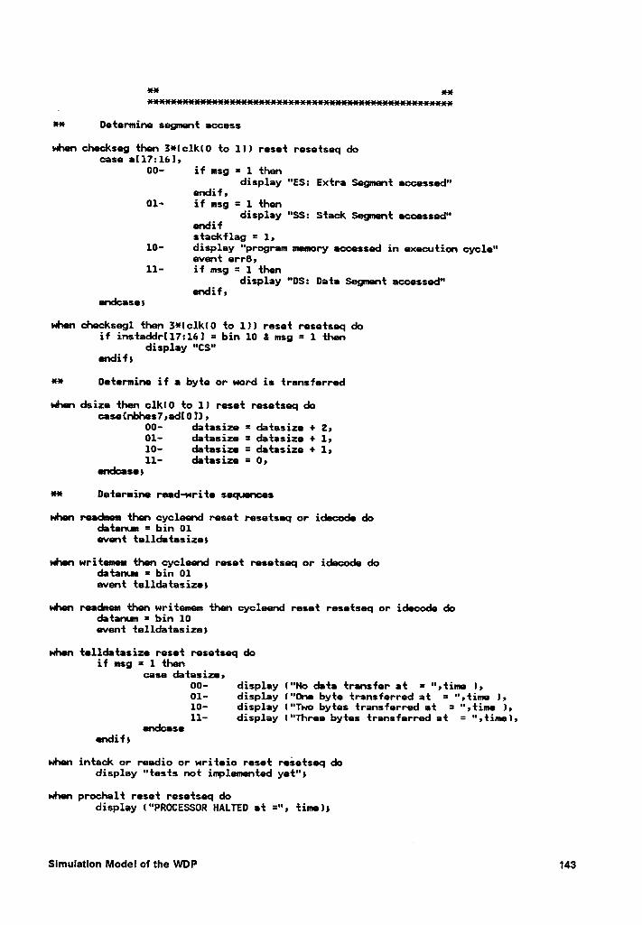
·¤·* am
·¤·* De{ermine segnen{ access
when checkseg {hen 3¤·(clk(0 {0 1)) rese{ rese{seq docase aI17:16],
00- if msg = 1 {hendisplay "ES: Ex{ra Segmen{ accessed"
endif,01- if msg = 1 {hen
display "SS: S{ack Segnen{ accessed"endifs{ackflag = 1,
10- display "program memory aocessed in execu{ion cycle"even{ errß,
11- if msg = 1 {hendisplay "DS: Da{a Segnen{ accessed"
Qhdlf;endcasei
when checksegl {hen 3*(clk(0 {0 1)) rese{ rese{seq doif ins{addrI17:161 = bin 10 8 msg = 1 {hen
display "CS"endif}
¤·* De{ermine if a by{e or word is {ransferred
when dsize {hen c1k(0 {o 1) rese{ rese{seq docase{nbhes7,ad[0 1) ,
00- da{asize = da{asize + Zn01- da{asize = da{asize + 1,10- da{asize = da{asize + 1,11- da{asize = 0,
endcaseß
H De{ermine read-wri{e sequences
when readnem {hen cycleend rese{ rese{seq or idecode doda{anu• = bin 01even{ {el1da{asize$
when wri{emem {hen cycleend rese{ rese{seq or idecode doda{anun = bin 01even{ {ellda{asize;
when readmem {hen wri.{emem {hen cycleend rese{ rese{seq or idecode doda{anun = bin 10even{ {ellda{asize}
when {ellda{asize rese{ rese{seq doif msg = 1 {hen
case da{asize,00- display ("No da{a {ransfer a{ = “,{ime ),01- display ("One by{e {ransferred a{ = ",{ime 1,10- display ("Two by{es {ransferred a{ = ",{ime I,11- display ("Three by{es {ransferred a{ = ",{ime),
endcaseendif!
when in{ack or readio or wri{eio rese{ rese{seq dodisplay "{es{s no{ imp1emen{ed ye{";
when prochal{ rese{ rese{seq dodisplay ("PROCESSOR HALTED a{ =", {inne);
Simulation Model ol the WDP 143
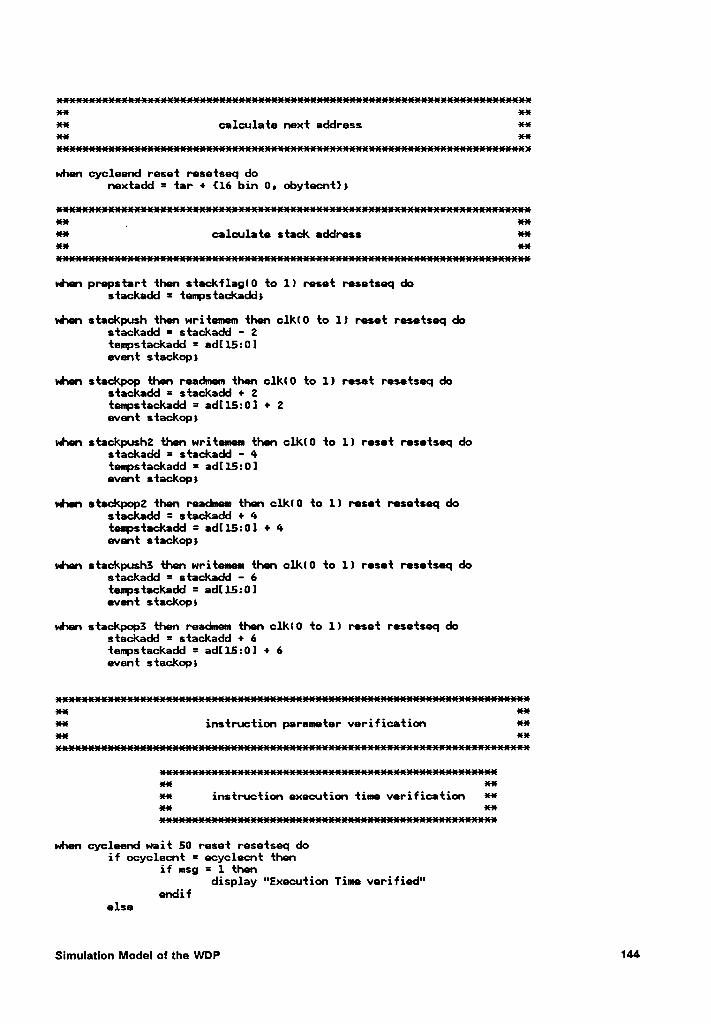
xxxxxxxxxxxxxx xxH calculate next address Hxx xxxxxxxxxxxxxxxxxxx
when cycleend reset resetseq denextadd = tar + {16 bin 0, obytecnt}1
xxxxxxxxx _ xxH caleulate stack address Hxx xx
when prepstart then stackflaglü to 1) reset resetseq destackadd = tenpstackadds
when stackpush then writemem then c1kl0 te 1) reset resetseq destackadd = stackadd - 2tempstackadd = adl15:01event stackop)
when stackpep then readmem then c1kl0 to 1) reset resetseq destackadd = stackadd + 2teumastackadd = ad|Z15:01 + 2event stackop)
when stackpushz then writemem then c1kl0 to 1) reset resetseq destackadd = stackadd - 4teupstackadd = adI15:0]event stackop)
vhen steckpepz then readnem then c1kl0 to 1) reset resetseq destackadd = stackadd + 4tespstackadd = ad[15:0l + 4event stackop)
when stackpuslß then writemem then c].k(0 to 1) reset resetseq destackadd = stackadd - 6teupstackadd = ad[15:0)event stackops
when stackpopä then readnem then c1k(0 to 1) reset resetseq destackadd = stackadd + 6tempstackadd = ad[15:01 + 6event stackop)
xx xxH instruction parameter verification Hxx xx
xx xxH instructien execution time verificatien Hxx xx
xxxxx
when cycleend wait 50 reset resetseq deif ecyclecnt = ecyclecnt then
if msg = 1 thendisplay "Exeeution Time verified"
endifelse
Simulatlon Medal ef the WDP 144
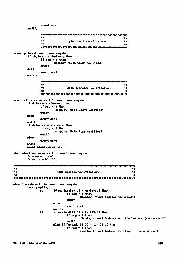
event errlendif;
as¤·as¤*asausas*xasasasasasasasasas¤asasasx*asas-xasasasasasasH aus
·¤·* byte count verifioation aus¤~¤· aus
auusas
when eyeleend reset resetseq doif ebytecnt = obytecnt then
if msg = 1 thendisplay "Byte Count verified"
endifelse
event •rr2endif)
asausausauusausas·¤·—¤· asas
** data transfer verification MH aus
ausausausasasasasas·asasasasasasasas
vdaen telldatasize wait 1 reset resetseq doif datanun = xfernun then
if msg = 1 then °display "Data Count verified"
endifelse
event err5endifif datasize = xfarsize then
if msg = 1 thendisplay "Data Size verified"endif '
elseevent err¢•
endifevent cleatimerparmsi
vhen cleatimerparms wait 1 reset resetseq dodatanun = bin 00datasize = bin 00;
aus ausH next address verification ·¤~¤·aus aus
when idecode wait 10 reset resetseq docase jurpflaga
00- if nextadd[19:0] = tarl19:0l thenif msg = 1 then
display l"Next Address verified")endif
elseevent err7
endif,01- if nextadd[19:0] = tar[l9:0] then
if msg = 1 thendisplay ("Next Address verified -- non jump opcode")
endifelse if junpadd[l9:0] = tar[19:0] then
if msg = 1 thendisplay ("Next Address verified —— jump taken")
Simulation Model of the WDP 145
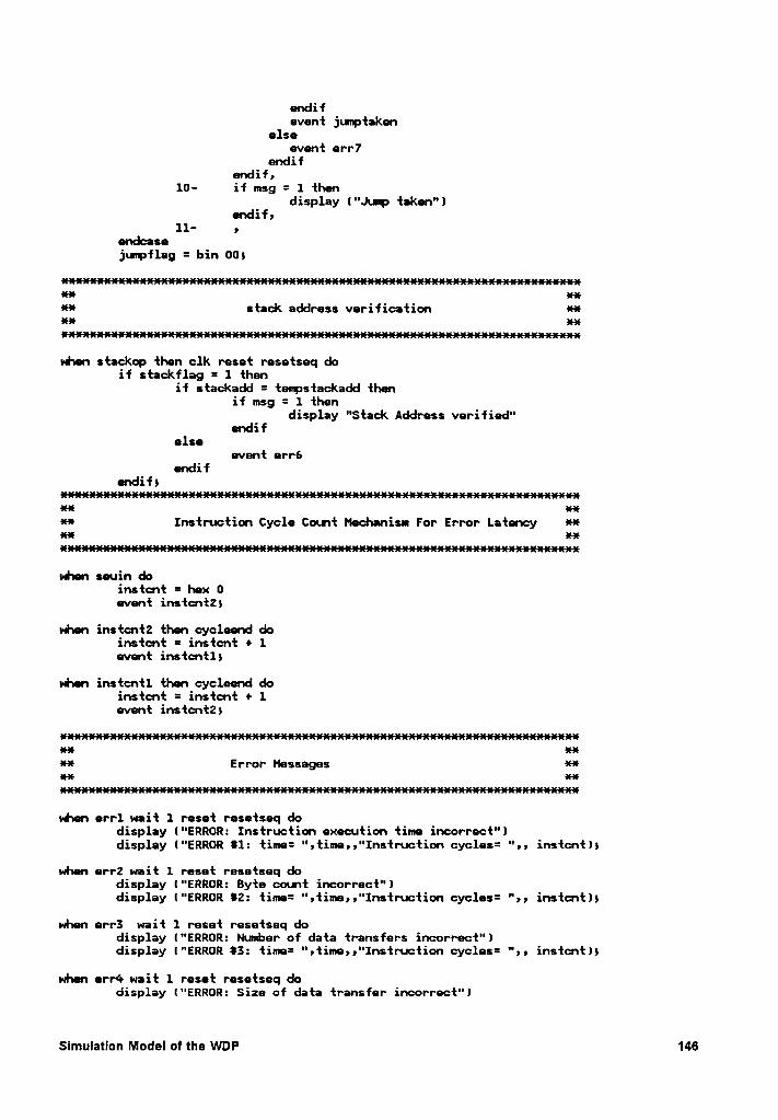
endifevent juuptaken
elseevent err7
endifendif,
10- if msg = 1 thendisplay ("Ju1p taken")
Chdify11- •
endcasejumflag = bin 00;
*l· er-16·¤~¤· stack address verification an-15IM *35
when stackop then clk reset resetseq doif stackflag = 1 then
if stackadd = tempstackadd thenif msg = 1 then
display "Stack Address verified"endif
elseevent err6
endifendif;
·¤·¤· auH Instruction Cycle Count Mechanisnn For Error Latency ·¤·¤·at-! xx
vdnen seuin doinstant = hex 0event instant2)
when instant2 tten cycleend deinstant = instcnt + 1event instantl;
when instcntl then cycleend doinstant = instant + 1event instant2;
ms xx
**Error Messages H
·¤·x·3535
when errl wait 1 reset resetseq dodisplay ("ERROR: Instruction execution time incorrect"ldisplay ("ERROR 81: time= ",time„"Instruction cycles= ",, instant);
when err2 wait 1 reset resetseq dodisplay ("ERROR: Byte count incorrect")display ("ERROR 82: time= ",time„"Instruction cycles= "„ instant);
when err3 wait 1 reset resetseq dodisplay ("ERROR: Number of data transfers incorrect"ldisplay l"ERROR 83: time= ",time;;"Instruction cycles= ";; instcntl;
when err4 wait 1 reset resetseq dodisplay ("ERROR: Size of data transfer incorrect")
Slmulatlon Model of the WDP 146
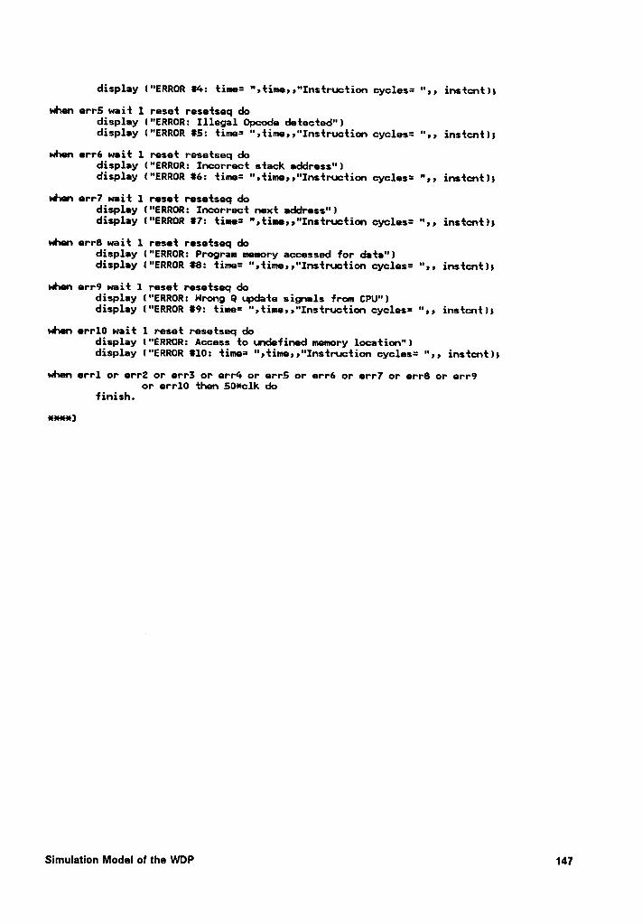
display ("ERROR 84: time= “,time,,"Instruction cycles= ",, instcnt)9
whn err5 wait 1 reset resetseq dodisplay ("ERROR: Illegal Opcode detected")display ("ERROR 85: time= ",time,,"Instruction cycles= ",, instcnt);
when err6 wait 1 reset resetseq dodisplay ("ERROR: Incorrect stack address")display ("ERROR 86: time= ",time,,"Instruction cycles= ",, instcnt);
when err7 wait 1 reset resetseq dodisplay ("ERROR: Incorrect next address")display ("ERROR 87: time= ",time,,"Instruction cycles= ",, instcnt);
when err8 wait 1 reset resetseq dodisplay ("ERROR: Program memory accessed for dta")display ("ERROR 88: time= ",time,,"Instruction cycles= ",, instcnt):
when err9 wait 1 reset resetseq dodisplay ("ERROR: Nrong Q update signals from CPU")display ("ERROR 89: time= ",time,,“Instruction cycles= ",, instcnt);
whn err1O wait 1 reset resetseq dodisplay ("ERROR: Access to undefined memory location")display ("ERROR 810: time= ",time,,"Instruction cycles= ",, instcnt);
when errl or err2 or err3 or err4 or err5 or err6 or err7 or err8 or err9or err10 then 50*clk do
finish.
xxxa)
Slmulatlon Model of the WDP 147
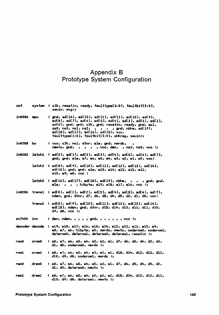
Appendix BPrototype System Configuration
ect system ( clk, resetin, ready, f:u1ttypel2:0l, f:ultbitI3:0l,seuin, msgls
in8086 upu ( god, :d[14], :dI13], :dl12], :d[11], :d[10l, :d[9l,2d[8]9 2d[7]9 2d[6]9 2d[5]9 2d[4]9 2d[3]9 adrzly 2d[1]9:dl0], gwd, gwd, clk, gsd, resetin, ready, gwd, qsl,QSÜ9 HSÜ9 h$19 I’\$29 9 9 9 9
g‘|d9I'!bh29:dl181,
:dl17l, :d[16], :d[151, vcc,f:u1ttype[2:0l, f:u1tbitI3:0l, chkreg, seuinls
in8288 bc ( vcc, clk, nsl, dtnr, :1e, god, nmrdc, ,I"IIUl‘tC9 g'\d9 Q Q Q Q VGC9 9
I’\$29HSÜ9 V¢C ls
ihB282 llidäl ( ICHÜI9 2d[1l9 ldtzln ICHSI9 2d[(Q]9 adtsl, 2d[6]9 Id[7lQgsd, gsd, :1e, :7, :6, :5, :4, :3, :2, :1, :0, vccl
:dl151, god, gxd, ale, :15, :14, :13, :12, :11,:10, :9, :8, vcc l
9 9 9 QÜ9 g'|d9:1e, , , , hibyte, :19, :18, :17, :16, vcc ls
in8286 transl ( :dI0l, :dI1l, :d[2l, :d[3l, :d[4l, adtsl, :d[6], :dI7],nden, Q!'|d9 dih|‘9 d79 d69 d59 d49 d39 d2, d19 dÜ9 VCC)
tr:ns2 ( :d[8], ad[9], :d[l0], adllll, ad[12], :d[13], ad[14],dl,29 dll) dlo)
d9, d8, vcc ls
decoder deoode ( :19, :18, :17, :16, :15, :14, :13, :12, :11, :10, :9,:8, :7, :6, hibyte, :0, nmrdc, mutc, coderom0, coderoml,d:t:rom0, dataroml, d:t:r:m0, d:t:r:ml, resetin ls
FOIIIÜ CPCIIIÜ ( 289 279 269 259 249 239 229 219 d7) d69 d5)d‘|9
d39 d2;dl, d0, coderomü, nmrdc ls
roml cronl ( :8, :7, :6, :5, :4, :3, :2, :1, d15, d14, d13, d12, dll,d10, d9, d8, coderoml, ruurdc ls
I‘2||IÜ d|‘2||l° [ 289 279 269 259 249 239 229 219 d7) d69 d59 d(O9 d3; d2;dl, dÜ9 d2t2P2IfI°9 I’Y|l{tC ls
l‘2l|I1 d|‘2I‘|1 ( 289 279 269 259 249 239 229219d10,d9, d8, dataraml, nnwtc ls
Prototyp: System Configuration 148
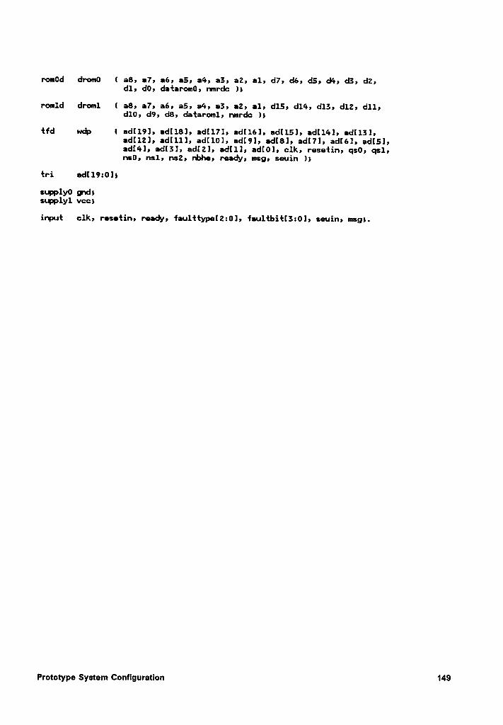
rom0d drom0 ( a8, a7, a6, a5, a4, a3, a2, al, d7, dé, d5, d•’•,d3, d2,
dl, d0, dafaromü, nmrdc ls
389 I79 I6) 35) 34; 839 I2) I1; dll,d10, d9, d8, dataroml, nmrdc 1;
{fd wdp ( ad[l9], •d[18], adl171, ad[l6], ad[15], ad[1¢•], •d[13]»ad[l2], adllll, ad[10], ad[9l, ad[8], adI7], ad[6], ad[5],ad[4], ad[3], ¤d[2l, adlll, ad[0], clk, rasatin, qs0, qsl,ns0, nsl, ns2, nbhc, ready, msg, sauin J;
{ri •dI19:015
s(.pp1y0 gudssnpplyl vccs
input clk, rosefin, raady, fau1‘H:ypa[2:0l, fau1{bi.f[3:0], sauin, msg;.
Prototype Systam Configuration1
149
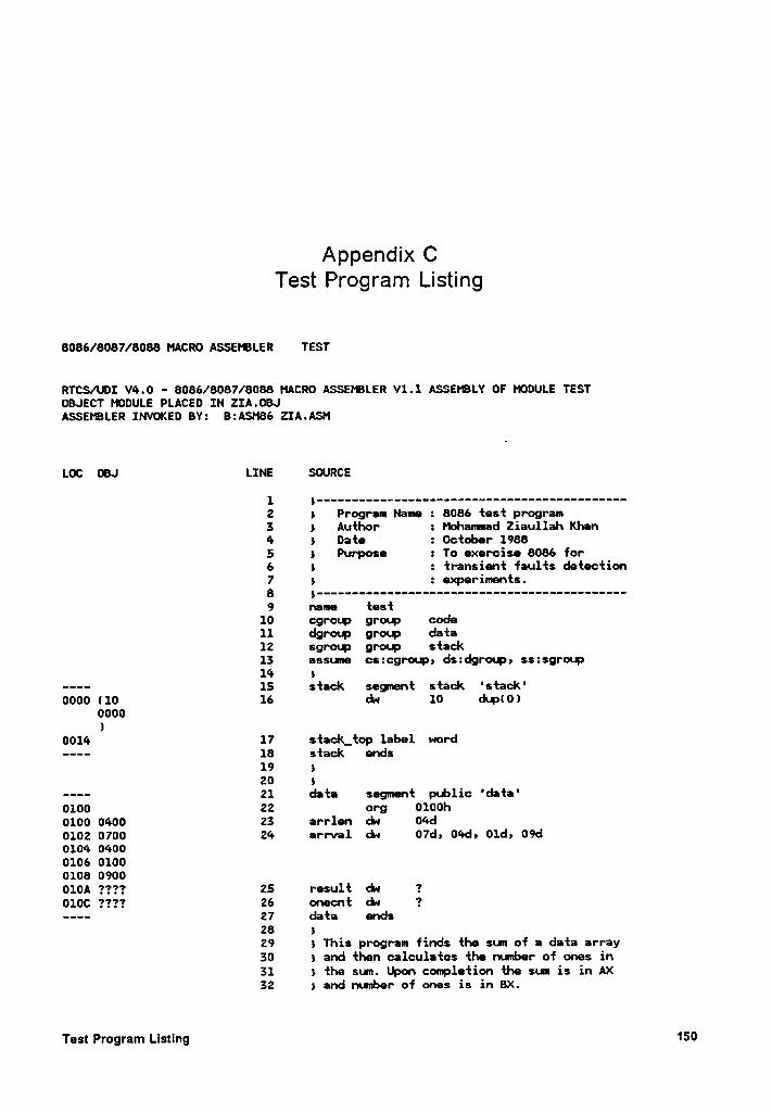
Appendnx CTest Program Lustmg
8086/8087/8088 MACRO ASSEPBLER TEST
RTCS/UDI V4.0 - 8086/8087/8088 MACRO ASSEPBLER V1.1 ASSEtBLY OF MODULE TESTOBJECT MODULE PLACED IN Z1A.OBJASSEIBLER INVOKED BY: B:ASM86 ZIA.ASM
LOC OBJ LINE SOURCE
1 S ''*'•''''''''''••'•''''*''•''''''''·•·•·••·•2 5 Program Name : 8086 test program3 5 Author : Mohanmad Ziaullah Khan4 5 Date : October 19885 5 Purposa : To exercise 8086 for6 5 : transient faults detection7 5 : experiments.8 5 ---—--—··------------—-—-—·----------------—9 name test
10 cgroup group code11 dgrotp group data12 sgroup group stack13 assune cszcgroup, ds:dgroup5 sszsgronp14 5
---- 15 stack segnent stack 'stack'0000 (10 16 dn 10 dup(0)
0000l
0014 17 stack_top label word———- 18 stack ends
19 520 5
---- 21 data segment pxblic 'data'0100 22 org 01ooh0100 0400 23 arrlen du 04d0102 0700 24 arrval zu 07d, 04d, 01d5 09d0104 04000106 01000108 0900010A ???? 25 result dn ?010C ???? 26 onecnt ck ?-—-- 27 data ends
28 529 5 This program finds the sun of a data array30 5 and then calculates the nweber of ones in31 5 the sun. Upon conpletion the sum is in AX32 5 and nunber of ones is in BX.
Test Program Listing 150
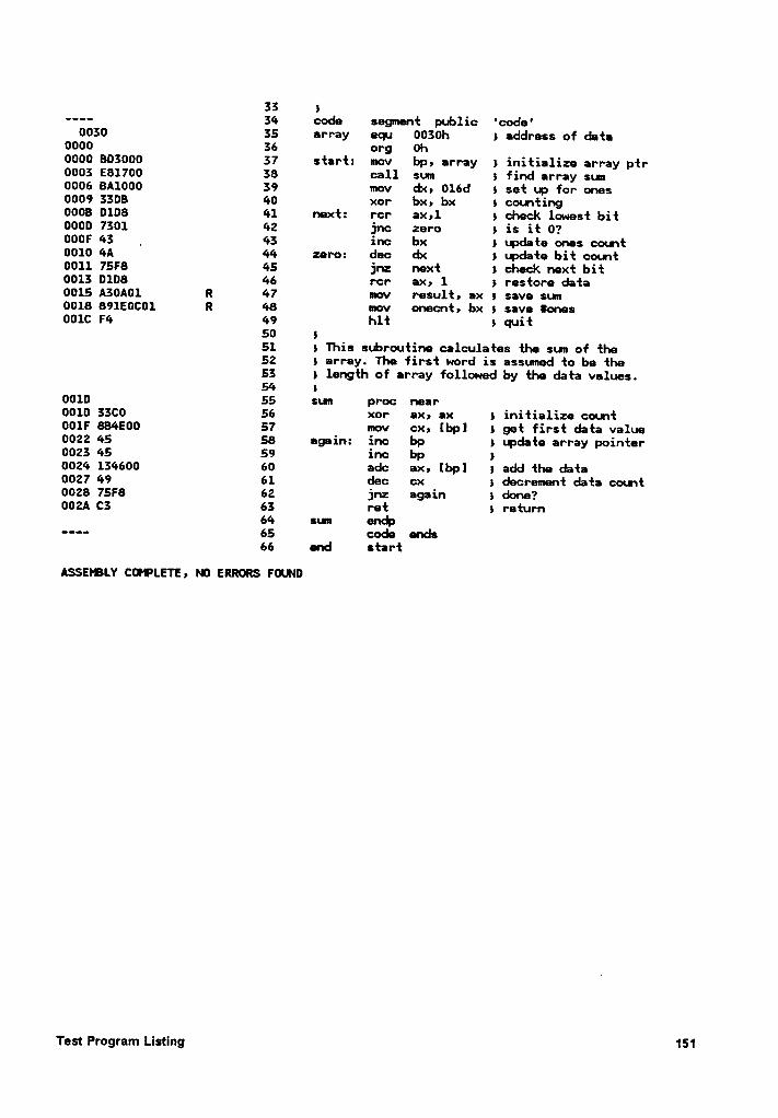
SS I—--- 34 code segment public 'code'
0030 35 array equ 0030h 1 address of data0000 36 org 0h0000 803000 37 start: mov bp, array 1 initialize array ptr0003 E81700 38 call sum 1 find array sun0006 8A1000 39 mov dx, 016d 1 set up for ones0009 3308 40 xor bx, bx 1 coemting0008 0108 41 next: rcr ax,1 1 check lowest bit0000 7301 42 jnc zero 1 is it 0?000F 43 _ 43 inc bx 1 update ones count0010 4A 44 zero: dec dx 1 update bit count0011 75F8 45 jrz next 1 check next bit0013 0108 46 rcr ax, 1 1 restore data0015 A30A01 R 47 mov result, ax 1 save sun0018 891EOC01 R 48 mov onecnt, bx 1 save {ones001C F4 49 hlt 1 quit
50 151 1 This subroutine calculates the sum of the52 1 array. The first word is assumed to be the53 1 length of array followed by the data values.54 I
0010 55 sun proc near0010 33C0 56 xor ax, ax 1 initialize count001F 8B4E00 57 mov cx, [bp] 1 get first data value0022 45 58 again: inc bp 1 update array pointer0023 45 59 inc bp 10024 134600 60 adc ax, [bp] 1 add the data0027 49 61 dec cx 1 decrement data count0028 7SF8 62 jnz again 1 done?002A C3 63 ret 1 return
64 sum en¢———— 65 code ends66 end start
ASSEIBLY CCHPLETE, M) ERRORS FGN0
Test Program Listing 151
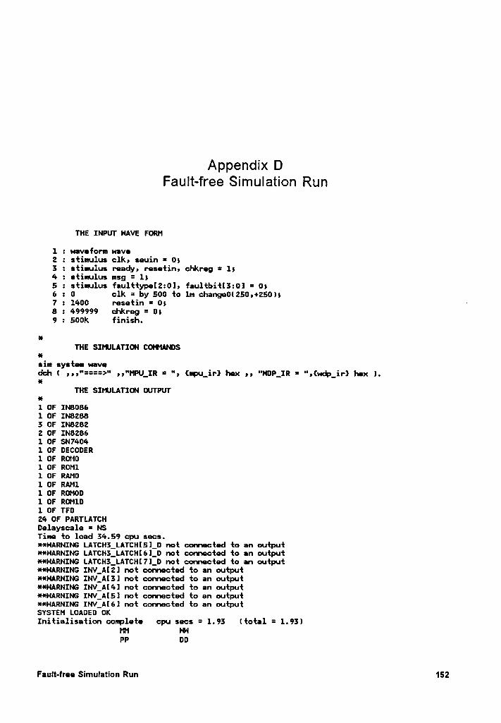
Appendux DFault-free Simulation Run
THE INPUT HAVE FORM
1 2 waveform wave2 : stimulus clk, seuin = 0;3 2 stimulus ready, resetin, chkreg = 1;4 2 stimulus msg = 1;5 2 stimulus fau1ttype[220], fau1tbitI3:0l = 0}6 2 0 clk = by 500 to 1m change0(250;+250);7 2 1400 resetin = 0;8 2 499999 chkreg = 0)9 2 500k finish.
anTHE SIPIJLATICN CGHANDS
essin system wavedd'! ( ;p)“====>" );""PU_IR = ") (I|PU_iI‘) Inex 9)"NDLIRas
THE SIMJLATION OUTPU‘l’an1 OF IN80861 OF IN8Z883 OF IN82822 OF IN82861 OF $N74041 OF DECODER1 OF ROM01 OF ROM11 OF RAM01 OF RAM11 OF ROM001 OF ROM1!)1 OF TF024 OF PARTLATCHDelayscale = NSTime to load 34.59 cpu secs.**NARNIN§ LATCH3_LATCH[5]_D not connected to an outputHNARNING LATCH3_LATCHI61_D not connected to an outputHHARNING LATCH3_LATCH[7J_D not connected to an output**HARNING INV_A[21 not connected to an output**HARNING INV_A[3l not connected to an output¥*HARNING INV_A[4] not connected to an output*·¤·HARNING INV_A[5] not connected to an output·¤··¤·HARNING INV_A[6] not connected to an outputSYSTEM LOADED OKInitialisation complete cpu secs = 1.93 (total = 1.93)
MM WPP DD
Fault-free Simulation Run 152
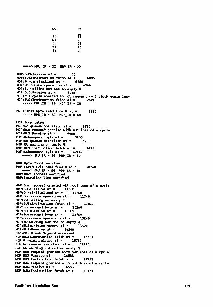
IN PP
II IIRR RR[I [I75 751] 1]
====> MPU_IR = XX HDP_IR = XX
NOP:BUS:Passive at = 80NDP:BU$:Instr•.uction fetch at = 6085NDP:Q reinitialized at = 6260HDP:No quueue operation at = 6760HDP:EU waiting but not on empty QHDP:BUS:Passive at = 7088HDP:bus cycle aborted for EU request -- 1 clock cycle lostHDP:BU$:Instruction fetch at = 7821
====> MPU_IR = BD NDP_IR = XX
Hl)P:First byte read from Q at = 8260====> MPU_IR = BD NDP_IR = BD
HOP:Juup takenHOP:No quueue operation at = 8760HDP:Bus request granted with out loss of a cycleNDP:BUS:Passive at = 9088NOP:Subsequent byte at = 9260HDP:No quueue operation at = 9760HDP:EU waiting on eerpty QNDP:BUS:Instruction fetch at = 9821NDP:$u.bsequent byte at = 10260
====> MPU_IR = EB HDP__IR = 80
HDP:Byte Count verifiedNOP:First byte read from 0 at = 10760
====> MPU_IR = E8 HDP_IR = E8NDP:Next Address verifiedHOP:Execution Time verified
HDP:Bus request granted with out loss of a cycleHDP:BU$:Passive at = 11088NDP:Q reinitialized at = 11260NDP:No quueue operation at = 11760NOP:EU waiting on empty QNOP:BUS:Instruction fetch at = 11821NOP:Subsequent byte at = 12260NOP:BUS:Passive at = 12589HOP:$u.bsequent byte at = 12760HOP:No quueue operation at = 15260HDP:EU waiting but not on enpty GNDP:BU$:writing meuuuory at = 15520NDP:BUS:Passive at = 14588HDP:$$: Stack Segunent accessedHDP:BUS:Instruction fetch at = 15521NOP:Q reinitialized at = 15760HDP:No quueue operation at = 16260HDP:EU waiting but not on empty 0NDP:Bus request granted with out loss of a cycleNDP:BU$:Passive at = 16588NDP:BU$:Instruction fetch at = 17521NOP:Bus request granted with out loss of a cycleNDP:BU$:Passive at = 18588HDP:BUS:Instruction fetch at = 19521
Fault-free Slmulatlon Run 153
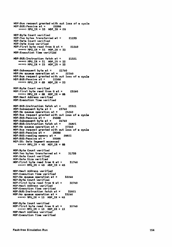
HDP:8us request granted with out loss of a cycleNOP:BUS:Passive at = 20588
====> MPU_IR = 33 HDP_IR = E8
NOP:Byte Count verifiedNDP:Two bytes transferred at = 21255HOP:Data Count verifiedHDP:Data Size verifiedHOP:First byte read from Q at = 21260
====> MPU_IR = 33 HDP_IR = 33NOP:Execution Time verified
HOP:8US:Instruction fetch at = 21321====> MPU_IR = 31 NDP_IR = 33====> MPU_IR = 33 HOP_IR = 33
NOP:S•.bsequent byte at = 21760HOP:No quueue operation at = 22260NDP:Bus request granted with out loss of a cycleNOP:BUS:Passive at = 22588
====> MPU__IR = 88 NOP__IR = 33
NDP:8yte Coent verifiedHDP:First byte read from Q at = 23260
====> MPU_IR = 88 N¤P_IR = 88HDP:Next Address verifiedNDP:Execution Time verified
NDP:BUS:Instruction fetch at = 23321NDP:Subsequent byte at = 23760NDP:No quueue operation at = 24260NDP:8us request granted with out loss of a cycleNOP:8U$:Passive at = 24588HDP:Subsequent byte at = 26760HOP:8US:Instruction fetch at = 26821NDP:No quueue operation at = 27260NOP:Bus request granted with out loss of a cycleNOP:BU$:Passive at = 28088HDP:8US:reading memory at = 28821HDP:8U$:Passive at = 30088HDP:DS: Data Segnent accessed
====> MPU_IR = 45 H¤P_IR = 88
HDP:Byte Count verifiedNDP:Two bytes transferred at = 31755NOP:0ata Count verifiedNOP:Data Size verifiedNOP:First byte read from Q at = 31760
====> MPU_IR = 45 N¤P_IR = 45
NDP:Next Address verifiedHDP:Execution Time verifiedNOP:No quueue operation at = 32260NDP:8yte Count verifiedNOP:First byte read from Q at = 32760NOP:Next Address verifiedHDP:Execution Time verifiedNDP:BUS:Instru•ction fetch at = 32821NDP:No quueue operation at = 33260
====> HPU_IR = 13 NOP_IR = 45
NDP:Byt• Count verifiedNDP:First byte read from Q at = 33760
====> MPU_IR = 13 NDP_IR = 13NOP:Next Address verifiedHDP:Execution Time verified
Fault-free Slmulatlon Run 154
HDP:Bus request granted with out loss of e cycle====> MPU_IR = 11 HDP_IR = 13
HDP:BU$:Passive et = 34088NDP:Subsequent byte et = 34260HDP:No quueue operation at = 34760NDP:BU$:Instruction fetch at = 34821HDP:Bus request granted with out loss of a cycleNDP:BU$:Passive at = 36088NDP:Subsequent byte at = 37260HOP:No quueue operation at = 37760HDP:BU$:reading memory et = 38821NDP:BU$:Passive at = 40088HDP:DS: Data Segment eccessed
====> MPU_IR = 13 NDP_IR = 13
====> MPU_IR = 49 NDP_IR = 13
NDP:Byte Count verifiedHDP:Two bytes transferred et = 42755NOP:Data Count verifiedNOP:Data Size verifiedHDP:First byte read from Q at = 42760
====> MPU_IR = 49 NDP_IR = 49NDP:Next Address verifiedNDP:Execution Time verified
NDP:BUS:Instruction fetch at = 42821HDP:No quueue operation at = 43260
====> MPU_IR = 75 HDP_IR = 49
HDP:8yte Count verifiedNDP:First byte read from Q et = 43760
====> MPU_IR = 75 NDP_IR = 75HDP:Next Address verifiedHOP:Execution Time verified
HOP:8us request granted with out loss of e cycleHDP:8U$:Passive at = 44088HDP:Subsequent byte et = 44260HDP:No quueue operation et = 44760HDP:Q reinitielized at = 48260NDP:BU$:Instruction fetch at = 48321NDP:No quueue operation at = 48760NDP:EU waiting but not on empty QNDP:Bus request granted with out loss of a cycleHDP:BU$:Passive at = 49588HDP:BUS:Instruction fetch at = 50321HDP:Bus request granted with out loss of e cycle
====> MPU_IR = 45 NDP_IR = 75
HDP:BUS:Passive at = 51588NDP:Byte Count verifiedNDP:First byte read from Q at = 51760
====> MPU_IR = 45 HDP_IR = 45
HDP:Next Address verified -- junp tekenHDP:Execution Time verifiedNDP:No quueue operation at = 52260NOP:BUS:Instruction fetch et = 52321HDP:Byte Count verifiedHDP:First byte read from Q at = 52760NDP:Next Address verifiedHDP:Execution Time verifiedNDP:No qu•ueue operation at = 53260HDP:Bus request granted with out loss of a cycle
====> MPU_IR = 13 NDP_IR = 45
Fault-free Simulatlon Run 155
NOP:BUS:Passive at = 53588NOP:Byte Count verifiedHOP:First byte read from Q at = 53760
====> MPU_IR = 13 H¤P_IR = 13
NDP:Next Address verifiedHDP:Execution Time verified
====> MPU_IR = 11 HDP_IR = 13
HOP:Subsequent byte at = 54260NDP:BU:Instruction fetch at = 54321NOP:No quueue operation at = 54760NDP:Bus request granted with out loss of a cycleHDP:BUS:Passive at = 55588HDP:BUS:Instruction fetch at = 56321NDP:Subsequent byte at = 57260NOP:Bus request granted with out loss of a cycleHDP:BU$:Passive at = 57588HDP:No quueue operation at = 57760HOP:BU$:reading memory at = 58821NDP:BUS:Passive at = 60088NDP:0S: Data Segment accessed
====> MPU_IR = 13 NDP_IR = 13
====> MPU_IR = 49 HDP_IR = 13
NDP:Byte Count verifiedHDP:Two bytes transferred at = 62755HDP:0ata Count verifiedHOP:Data Size verifiedHDP:First byte read from Q at = 62760
====> MPU_IR = 49 NDP_IR = 49HDP:Next Address verifiedNDP:Execution Time verified
HOP:BUS:1nstruction fetch at = 62821NOP:No quueue operation at = 63260
====> MPU_IR = 75 HDP_IR = 49
HDP:Byte Count verified _NDP:First byte read from Q at = 63760
====> MPU_IR = 75 NDP_IR = 75NDP:Next Address verifiedHOP:Execution Time verified
HDP:Bus request granted with out loss of a cycleHDP:BUS:Passive at = 64088NDP:Subsequnt byte at = 64260HDP:No quueue operation at = 64760NDP:Q reinitialized at = 68260NOP:BUS:Instruction fetch at = 68321NDP:No quueue operation at = 68760NDP:EU waiting but not on empty 0HOP:Bus request granted with out loss of a cycleHDP:BU$:Passive at = 69588NDP:BUS:Instruction fetch at = 70321HDP:Bus request granted with out loss of a cycle
====> MPU_IR = 45 NDP_IR = 75
H¤P:BUS:Passive at = 71588NDP:Byte Count verifiedHOP:First byte read from Q at = 71760
====> MPU_IR = 45 H¤P_IR = 45
HDP:Next Address verified -- jump takenHOP:Execution Time verified
Fault-free SlmulatlonRun156
HDP:No quueue operation at = 72260NDP:BU$:Instruction fetch at = 72321NOP:Byte Count verifiedNDP:First byte read from Q at = 72760NDP:Next Address verifiedHDP:Execution Time verifiedHDP:No quueue operation at = 73260NDP:Bus request granted with out loss of e cycle
====> MPU_IR = 13 HDP_IR = 45
NDP:BUS:Passive at = 73588NDP:Byte Count verifiedNDP:First byte read from Q et = 73760
====> MPU_IR = 13 NDP_IR = 13
N¤P:Next Address verifiedNDP:Execution Time verified
====> MPU_IR = ll NDP_IR = 13
NDP:Subsequent byte et = 74260NDP:8US:Instruction fetch at = 74321NDP:No quueue operation at = 74760HDP:Bus request granted with out loss of e cycleNDP:BUS:Passive at = 75588HDP:8US:Instruction fetch at = 76321HDP:Subsequent byte at = 77260HDP:Bus request granted with out loss of a cycleNDP:8US:Passive at = 77588NDP:No quueue operation at = 77760NOP:BUS:reading mmory at = 78821HOP:BUS:Passive at = 80088HDP:DS: Data Segment accessed
====> MPU_IR = 13 HDP_IR = 13
====> MPU_IR = 49 HDP_IR = 13
HDP:Byte Count verifiedNDP:Two bytes transferred et = 82755NDP:Data Count verifiedNDP:Data Size verifiedNDP:First byte read from Q at = 82760
====> MPU_IR = 49 NDP_IR = 49HDP:Next Address verifiedHDP:Execution Time verified
NDP:8US:Instruction fetch at = 82821HDP:No quueue operation at = 83260
====> MPU_IR = 75 HOP_IR = 49
HDP:8yte Count verifiedHDP:First byte read from Q at = 83760
====> MPU_IR = 75 NDP_IR = 75NDP:Next Address verifiedNDP:Execution Time verified
NDP:Bus request granted with out loss of a cycleNDP:BU:Passive at = 84088HDP:Subsequent byte at = 84260NDP:No quueue operation at = 84760HDP:Q reinitialized at = 88260NOP:BU$:Instruction fetch at = 88321NDP:No quueue operation at = 88760HDP:EU waiting but not on empty QHDP:8us request granted with out loss of a cycleHDP:BUS:Passive at = 89588HOP:BUS:Instruction fetch at = 90321NDP:Bus request granted with out loss of a cycle
Fault-free Simulation Run 157
====> MPU_IR = 45 HDP_IR = 75
HDP:BU$:Passive at = 91588HDP:Byte Count verifiedNDP:First byte read from Q at = 91760
====> MPU_IR = 45 NDP_IR = 45
NDP:Next Address verified -- jump takenHDP:Execution Time verifiedHOP:No quueue operation at = 92260NOP:BUS:Instruction fetch at = 92321HDP:Byte Count verifiedNDP:First byte read from Q at = 92760NDP:Next Address verifiedNOP:Execution Time verifiedHOP:No Queue operation at = 93260NDP:Bus request granted with out loss of a cycle
====> MPU_IR = 13 NDP_IR = 45
HDP:BUS:Passive at = 93588NDP:Byte Count verifiedHDP:First byte read from Q at = 93760
====> MPU_IR = 13 NDP_IR = 13
HOP:Next Address verifiedHDP:Execution Time verified
====> MPU_IR = 11 HDP_IR = 13
H0P:SubseQ1ent byte at = 94260NDP:BU$:Instruction fetch at = 94321NDP:No QIJBUB operation at = 94760HDP:Bus request granted with out loss of a cycleNDP:BU$:Passive at = 95588HOP:BU$:Instruction fetch at = 96321NOP:Subsequent byte at = 97260NOP:8us request granted with out loss of a cycleHDP:BU$:Passive at = 97588HDP:No quueue operation at = 97760NDP:BUS:reading memory at = 98821NDP:BU$:Passive at = 100088HDP:0$: Data Segnent accessed
====> MPU_IR = 13 NDP_IR = 13
====> MPU_IR = 49 HOP_IR = 13
HDP:Byte Count verifiedHOP:Two bytes transferred at = 102755NOP:0ata Count verifiedNDP:-Data Size verifiedHDP:First byte read from Q at = 102760
====> MPU_IR = 49 HDP_IR = 49HDP:Next Address verifiedHOP:Execution Time verified
NDP:8US:Instruction fetch at = 102821NDP:No quueue operation at = 103260
====> MPU_IR = 75 NDP_IR = 49
HDP:Byte Count verifiedNOP:First byte read from 0 at = 103760
====> MPU_IR = 75 HDP_IR = 75l•lDP:Next Address verifiedNDP:Execution Time verified
NDP:Bus request granted with out loss of a cycleNDP:BU$:Passive at = 104088HDP:Subsequent byte at = 104260
Fault-lree Slmulatlon Run 158
HDP:No quueue operation at = 104760NDP:BUS:Instruction fetch at = 104821
====> MPU_IR = C3 N¤P_IR = 75
HDP:BUS:Passive at = 105589NDP:Byte Count verifiedHDP:First byte read from Q at = 105760
====> MPU_IR = C3 HDP_IR = C3
NDP:Next Address verified —— non jup opcodeNDP:Execution Time verifiedNDP:No quueue operation at = 106260HDP:BUS:re•ding mmory at = 106320NDP:Stack Address verifiedH¤P:BUS:Passive at = 107588NDP:SS: Stack Segment accessedHDP:BUS:Instruction fetch at = 108321NDP:Q reinitialized at = 109260HDP:Bus request granted with out loss of a cycleHDP:BUS:Passive at = 109588 _HDP:No quueue operation at = 109760NDP:EU waiting but not on empty QHDP:BUS:Instruction fetch at = 110321
====> MPU_IR = BA NDP_IR = C3
NDP:Byte Count verifiedNOP:Two bytes transferred at = 110755NDP:0ata Count verifiedHDP:Data Size verifiedHDP:First byte read from Q at = 110760
====> MPU_IR = BA HOP_IR = BA
NDP:Execution Time verifiedNDP:No quueue operation at = 111260NDP:Bus request granted with out loss of a cycleNDP:BU$:Pessive at = 111588HDP:Subsequnt byte at = 111760HDP:No quueue operation at = 112260HDP:EU waiting on empty 0NDP:BUS:Instruction fetch at = 112321HDP:Subsequent byte at = 112760
====> MPU_IR = 33 NDP_IR = BA
HDP:Byte Count verifiedHDP:First byte read from Q at = 113260
====> MPU_IR = 33 NDP_IR = 33NDP:Next Address verifiedNDP:Execution Time verified
NOP:8us request granted with out loss of a cycleNDP:BUS:Passive at = 113588HDP:Q reinitialized at = 113760NDP:No quueue operation at = 114260HDP:EU waiting on empty 0NDP:BU$:Instruction fetch at = 114321
====> MPU_IR = 31 HOP_IR = 33====> MPU_IR = 33 HOP_IR = 33
NDP:Subsequent byte at = 114760NDP:No quueue operation at = 115260NOP:Bus request granted with out loss of a cycleNDP:BUS:Passive at = 115588
====> MPU_IR = D1 HDP_IR = 33
NDP:Byte Count verifiedHDP:First byte read from Q at = 116260
Fault-free Simulation Run _ 159

====> MPU_IR = D1 NDP_IR = D1NDP:Next Address verifiedNOP:Execution Time verified
NDP:BUS:Instruction fetch at = 116321====> MPU_IR = 51 HDP_IR = D1
HOP:$ubsequnt byte at = 116760====> MPU_IR = 73 HOP_IR = D1
HDP:Byte Count verifiedNDP:First byte read from Q at = 117260
====> MPU_IR = 73 NDP_IR = 73HOP:Next Address verifiedNDP:Execution Time verified
HOP:Bus request granted with out loss of a cycleNOP:8U$:Passive at = 117588NDP:0 reinitialiked at = 117760HDP:No quueue operation at = 118260NDP:EU waiting on empty QHDP:BUS:Instruction fetch at = 118321NDP:$ubsequent byte at = 118760HDP:No quueue operation et = 119260NOP:Bus request granted with out loss of a cycleHOP:BU$:Passive at = 119588
====> MPU_IR = 43 HDP_IR = 73
NOP:Byte Count verifiedHOP:First byte read from Q at = 120260
====> MPU_IR = 43 NDP_IR = 43HOP:Next Address verified -— non jump opcodeNOP:Execution Time verified
HDP:BUS:Instruction fetch et = 120321HDP:No quueue operation at = 120760
====> MPU_IR = 4A HDP_1R = 43
HOP:Byte Count verifiedHOP:First byte read from Q at = 121260
====> MPU_IR = 4A HDP_IR = 4AHDP:Next Address verifiedNOP:Execution Time verified
NDP:Bus request granted with out loss of a cycleN¤P:BUS:Passive at = 121588NDP:No quueue operation at = 121760
====> MPU_IR = 75 NDP_IR = 4A
HDP:Byte Count verifiedNOP:First byte read from Q at = 122260
====> MPU_IR = 75 NDP_IR = 75NOP:Next Address verifiedHDP:Execution Time verified
NDP:BUS:Instruction fetch at = 122321NOP:$ubsequent byte at = 122760HDP:No quueue operation at = 123260HOP:Bus request granted with out loss of a cycleNOP:BU:Passive at = 123588NOP:Q reinitialized at = 127260HDP:BUS:Instruction fetch at = 127321NOP:No quueue operation at = 127760HDP:EU waiting but not on empty 0NDP:Bus request granted with out loss of a cycleHDP:BUS:Passive at = 128588HDP:BUS:Instruction fetch at = 129321
Fault-free Simulation Run 160
====> MPU_IR = 01 NOP_IR = 75 „
NDP:Byte Count verifiedHDP:First byte read from Q at = 130260
====> MPU_IR = 01 NOP_IR = D1NOP:Next Address verified -- jump takenHDP:Execution Time verified
NOP:Bus request granted with out loss of a cycleNDP:BUS:Passive at = 130588HOP:Q reinitialized at = 130760NDP:No quueue operation at = 131260HOP:EU waiting on mpty GNOP:BUS:Instruction fetch at = 131321
====> MPU_IR = 51 HDP_1R = D1
NOP:$ubsequnt byte at = 131760====> MPU__IR = 73 HOP_IR = 01
NDP:Byte Count verifiedNDP:First byte read from G at = 132260
====> MPU_IR = 73 HOP_IR = 73HDP:Next Address verifiedHDP:Execution Time verified
HDP:Bus request granted with out loss of a cycleHDP:BUS:Passive at = 132588NOP:Q reinitialized at = 132760NDP:No quueue operation at = 133260HOP:EU waiting on empty 0HDP:BU$:Instruction fetch at = 133321NDP:$ubsequent byte at = 133760NDP:No quueue operation at = 134260NDP:Bus request granted with out loss of e cycleNOP:BUS:Passive at = 134588NOP:Q reinitialized at = 138260NOP:BUS:Instruction fetch at = 138321NOP:No quueue operation at = 138760HDP:EU waiting but not on empty 0NDP:Bus request granted with out loss of a cycleHDP:BUS:Passive at = 139588HDP:BUS:Instruction fetch at = 140321
====> MPU_IR = 4A HDP_IR = 73
NDP:Byte Count verifiedNDP:First byte read from Q at = 141260
====> MPU_IR = 4A NOP_IR = 4ANDP:Next Address verified —- jump takenNOP:Execution Time verified
HOP:Bus request granted with out loss of • cycleHDP:BUS:Passive at = 141588HOP:No quueue operation at = 141760
====> HPU_IR = 75 NOP_IR = 4A
HOP:Byte Count verifiedNDP:First byte read from G at = 142260
====> MPU_IR = 75 HOP_IR = 75NOP:Next Address verifiedNOP:Execution Time verified
NDP:BUS:Instruction fetch at = 142321HDP:$ubsequent byte at = 142760NOP:No quueue operation at = 143260NOP:Bus request granted with out loss of a cycleN¤P:BU$:Passive at = 143588NOP:Q reinitialized at = 147260
Fault-free Slmulatlon Run 161
HOP:BU$:Instruction fetch at = 147321NDP:No quueue operation at = 147760NOP:EU waiting but not on empty QHOP:Bus request granted with out loss of a cycleHOP:BU$:Passive at = 148588HOP:BUS:Instruction fetch at = 149321
====> MPU_IR = 01 HDP_IR = 75
HDP:8yte Count verifiedNOP:First byte read from 0 at = 150260
====> MPU_IR = D1 HDP_IR = 01HOP:Next Address verified ·- jump taknNOP:Execution Time verified
NDP:Bus request granted with out loss of a cycleNDP:BUS:Passive at = 150588HDP:G reinitialized at = 150760HOP:No quueue operation at = 151260HDP:EU waiting on epty 0HDP:BU$:Instruction fetch at = 151321
====> MPU_IR = 51 NDP_IR = D1
NOP:Subsequent byte at = 151760====> MPU_IR = 73 HOP_IR = D1
HOP:Byte Count verifiedNDP:First byte read from Q at = 152260
====> MPU_IR = 73 NDP_IR = 73NOP:Next Address verifiedNOP:Execution Time verified
NDP:Bus request granted with out loss of a cycleNDP:BU$:Passive at = 152588NDP:Q reinitialized at = 152760HOP:No quueue operation at = 153260HOP:EU waiting on mpty QHDP:BUS:Instruction fetch at = 153321HDP:$ubsequent byte at = 153760NOP:No quueue operation at = 154260NDP:Bus request granted with out loss of a cycleHDP:BU$:Passive at = 154588
====> MPU_IR = 43 HOP_IR = 73
NOP:Byte Count verifiedNOP:First byte read from Q at = 155260
====> MPU_IR = 43 H¤P_IR = 43NOP:Next Address verified —- non jump opcodeHOP:Execution Time verified
HOP:BUS:Instruction fetch at = 155321HOP:No quueue operation at = 155760
====> MPU_IR = 4A HDP__IR = 43
NOP:Byte Count verifiedHDP:First byte read from G at = 156260
====> MPU_IR = 4A NOP_IR = 4ANDP:Next Address verifiedNOP:Execution Time verified
HOP:Bus request granted with out loss of a cycleNOP:BUS:Passive at = 156588HOP:No quueue operation at = 156760
====> MPU_IR = 75 NDP_IR = 4A
HOP:8yte Count verifiedNOP:First byte read from Q at = 157260
Fault-free Slmulatlon Run 162
====> MPU_IR = 75 N¤P_IR = 75HOP:Next Address verifiedNDP:Execution Time verified
HDP:BU$:Instruction fetch at = 157321NDP:$ubsequent byte at = 157760
— HDP:No quueue operation at = 158260NDP:Bus request granted with out loss of a cycleHOP:BU$:Passive at = 158588HOP:Q reinitialized at = 162260HDP:BUS:Instruction fetch at = 162321HDP:No quueue operation at = 162760NDP:EU waiting but not on mpty QNDP:Bus request granted with out loss of a cycleNDP:BUS:Passive at = 163588NDP:BUS:Instruction fetch at = 164321
====> MPU_IR = D1 NDP_IR = 75
NOP:Byte Count verifiedHDP:First byte read from Q at = 165260
====> MPU_IR = D1 NDP_IR = D1HDP:Next Address verified -~ jump taknHDP:Execution Time verified
N¤P:Bus request granted with out loss of a cycleNDP:BUS:Passive at = 165588NDP:Q reinitialized at = 165760HDP:No quueue operation at = 166260NDP:EU waiting on empty QNDP:BUS:Instruction fetch at = 166321
====> MPU_IR = 51 HDP_IR = D1
HOP:S•.bsequent byte at = 166760====> MPU_IR = 73 NDP_IR = D1
HOP:Byte Count verifiedNDP:First byte read from Q at = 167260
====> MPU_IR = 73 N¤P_IR = 73NDP:Next Address verifiedNDP:Execution Time verified
NDP:Bus request granted with out loss of a cycleNDP:8U$:Passive at = 167588HDP:Q reinitialized at = 167760HDP:No quueue operation at = 168260NDP:EU waiting on empty QHDP:BU$:Instruction fetch at = 168321NDP:$ubsequent byte at = 168760HDP:No quueue operation at = 169260HDP:Bus request granted with out loss of a cycleHDP:BU$:Passive at = 169588HOP:Q reinitialized at = 173260NDP:BUS:Instruction fetch at = 173321HDP:No quueue operation at = 173760HDP:EU waiting but not on empty QNOP:Bus request granted with out loss of a cycleNOP:BUS:Passive at = 174588HDP:BU$:Instruction fetch at = 175321
====> MPU_IR = 4A HOP_IR = 73
HDP:Byte Count verifiedNOP:First byte read from Q at = 176260
====> MPU_IR = 4A HDP_IR = 4AHOP:Next Address verified -- jump takenHDP:Execution Time verified
Fault·free Simulation Run 163
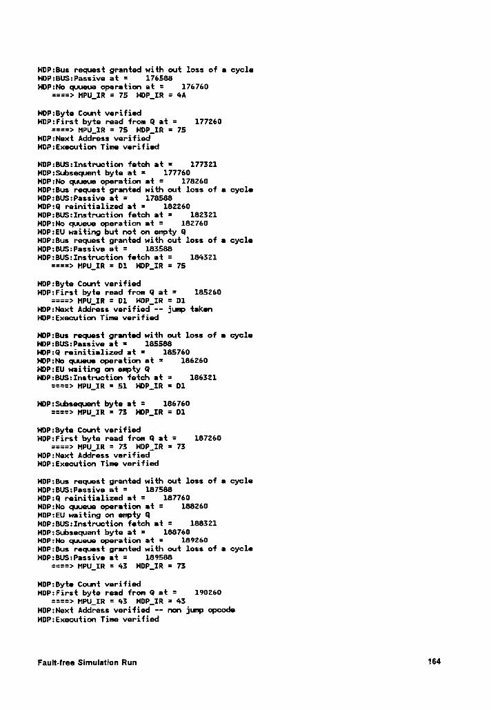
HDP:8us request granted with out loss of a cycleNOP:BU$:Passive at = 176588NDP:No cpueue operation at = 176760
====> MPU_IR = 75 NDP_IR = 4A
HOP:Byte Count verifiedNDP:First byte read from Q at = 177260
====> MPU_IR = 75 N¤P_IR = 75l·lDP:Next Address verifiedHOP:Execution Time verified
NOP:BUS:Instruction fetch at = 177321NDP:Subsequent byte at = 177760NDP:No qaueue operation at = 178260HOP:Bus request granted with out loss of a cycleNDP:BU$:Passive at = 178588NDP:Q reinitialized at = 182260HOP:BUS:Instruction fetch at = 182321NDP:No quueue operation at = 182760NDP:EU waiting but not on empty GNDP:Bus request granted with out loss of a cycleNDP:BU$:Passive at = 183588HOP:BUS:Instruction fetch at = 184321
====> MPU_IR = 01 NDP_IR = 75
HOP:Byte Count verifiedNOP:First byte read from Q at = 185260
====> HPU_IR = D1 HDP_IR = D1HDP:Next Address verified -— jump takenNOP:Execution Time verified
HOP:Bus request granted with out loss of e cycleNOP:8US:Passive at = 185588HDP:Q reinitialized at = 185760HOP:No quueue operation at = 186260NDP:EU waiting on enpty 0HDP:BU$:Instru•ction fetch at = 186321
====> MPU_IR = 51 HDP_IR = 01
HOP:Subsequent byte at = 186760====> MPU_IR = 73 H¤P_IR = D1
HDP:Byte Count verifiedNDP:First byte read from Q at = 187260
====> MPU_IR = 73 NDP_IR = 73l·l0P:Next Address verifiedHDP:Execution Time verified
HDP:Bus request granted with out loss of a cycleNDP:BU$:Passive at = 187588NOP:Q reinitialized at = 187760HDP:No quueue operation at = 188260NOP:EU waiting on empty 0HDP:BUS:Instruction fetch at = 188321HDP:$ubsequent byte at = 188760NDP:No quueue operation at = 189260HDP:Bus request granted with out loss of a cycleHDP:BU$:Passive at = 189588
====> MPU_IR = 43 HOP_IR = 73
NDP:Byte Count verifiedNDP:First byte read from Q at = 190260
====> MPU_IR = 43 NOP_IR = 43HOP:Next Address verified -- non jump opcodeHDP:Executi0n Time verified
Fault-free Simulation Run 164
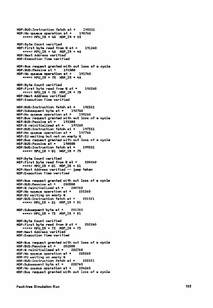
HDP:BU$:Instruction fetch at = 190321HDP:No quueue operation at = 190760
====> MPU_IR = 4A NDP_IR = 43
NOP:Byte Count verifiedNDP:First byte read from Q at = 191260
====> MPU_IR = 4A NDP_IR = 4ANOP:Next Address verifiedNDP:Execution Time verified
NDP:Bus request granted with out loss of a cycleHDP:BU$:Passive at = 191588NDP:No quueue operation at = 191760
====> MPU_IR = 75 NDP_IR = 4A
NDP:Byte Count verifiedNDP:First byte read from Q at = 192260
====> MPU_IR = 75 NDP_IR = 75NDP:Next Address verifiedHOP:Execution Time verified
NDP:BUS:Instruction fetch at = 192321N¤P:$ubsequent byte at = 192760HDP:No quueue operation at = 193260NOP:Bus request granted with out loss of a cycleNOP:BUS:Passive at = 193588NDP:Q reinitialized at = 197260NDP:BUS:Instruction fetch at = 197321NOP:No quueue operation at = 197760NDP:EU waiting but not on empty QNDP:Bus request granted with out loss of a cycleHOP:BU$:Passive at = 198588NOP:BU$:Instruction fetch at = 199321
====> MPU_IR = D1 NOP_IR = 75
HDP:Byte Count verifiedNOP:First byte read from Q at = 200260
====> HPU_IR = D1 NOP_IR = 01HOP:Next Address verified -- jump takenNDP:Execution Time verified
NDP:Bus request granted with out loss of a cycleNDP:8U$:Passive at = 200588NOP:Q reinitialized at = 200760HDP:No quueue operation at = 201260HDP:EU waiting on empty QHDP:BUS:Instruction fetch at = 201321
====> MPU_IR = 51 NDP_IR = 01
NDP:Subsequent byte at = 201760====> MPU_IR = 73 HOP_IR = D1
HDP:Byte Count verifiedHDP:First byte read from Q at = 202260
====> MPU_IR = 73 NDP_IR = 73HDP:Next Address verifiedNOP:Execution Time verified
NDP:Bus request granted with out loss of a cycleHDP:BU$:Passive at = 202588HOP:Q reinitialized at = 202760NDP:No quueue operation at = 203260NOP:EU waiting on empty GHDP:BUS:Instruction fetch at = 203321HOP:Subsequent byte at = 203760NDP:No quueue operation at = 204260NDP:Bus request granted with out loss of a cycle
Fault-free SlmulatlonRun165
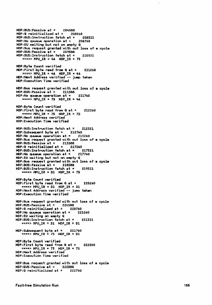
NDP:BU$:Passive at = 204588HDP:Q reinitialized at = 208260NOP:BUS:Instruction fetch at = 208321NDP:No quueue operation at = 208760NDP:EU waiting but not on empty QNDP:Bus request granted with out loss of e cycleHDP:BUS:Passive at = 209588HDP:BU$:Instruction fetch at = 210321
====> MPU_IR = 4A NDP_IR = 73
HDP:Byte Count verifiedNDP:First byte read from Q at = 211260
====> MPU_IR = 4A NDP_IR = 4AHDP:Next Address verified -- jump taknNDP:Execution Time verified
NOP:8us request granted with out loss of • cycleNDP:BU:Passive at = 211588NDP:No quueue operation at = 211760
====> MPU_IR = 75 HDP_IR = 4A
NDP:Byte Count verifiedHDP:First byte read from Q at = 212260
====> MPU_IR = 75 HDP_IR = 75HOP:Next Address verifiedNDP:Execution Time verified
HDP:BU$:Instruction fetch at = 212321NOP:Subsequent byte at = 212760HDP:No quueue operation at = 213260HDP:Bus request granted with out loss of a cycleNDP:BU$:Passive at = 213588NDP:Q reinitialized et = 217260NDP:BUS:Instruction fetch et = 217321NDP:No quueue operation at = 217760HDP:EU waiting but not on empty QHDP:Bus request granted with out loss of • cycleHDP:BU$:Passive at = 218588HOP:BU$:Instruction fetch at = 219321
====> MPU_IR = D1 HDP_IR = 75
NOP=8yte Count verifiedHDP:First byte read from Q at = 220260
====> MPU_IR = D1 HDP_IR = D1HDP:Next Address verified -- jump taknNDP:Execution Time verified
NDP:Bus request granted with out loss of a cycleHDP:BU$:Passive at = 220588NDP:Q reinitialized at = 220760NDP:No quueue operation at = 221260NOP:EU waiting on empty QHDP:BU$:Instruction fetch at = 221321
====> MPU_IR = 51 HDP_IR = D1
NDP:$ubsequent byte at = 221760====> MPU_IR = 73 NDP_IR = D1
NDP:Byte Count verifiedNDP:First byte read from Q at = 222260
====> MPU_IR = 73 HDP_IR = 73HDP:Next Address verifiedNDP:Execution Time verified
NDP:Bus request granted with out loss of a cycleNOP:BUS:Passive at = 222588HDP:Q reinitialized at = 222760
Fault-free Simulation Run 166
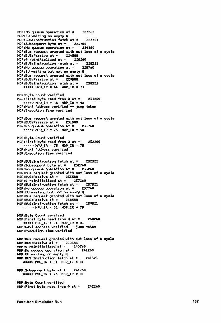
NOP:No quueue operation at = 223260NOP:EU waiting on empty QNDP:BU$:Instruction fetch at = 223321NDP:Subsequent byte at = 223760HDP:No quueue operation at = 224260NOP:Bus request granted with out loss of a cycleNDP:BUS:Passive at = 224588HOP:Q reinitialized at = 228260NOP:BU$:Instruction fetch at = 228321HOP:No quueue operation at = 228760HDP:EU waiting but not on empty QHOP:Bus request granted with out loss of e cycleHOP:BUS:Passive at = 229588NDP:BU$:Instruction fetch at = 230321
====> MPU_IR = 4A NDP_IR = 73
NDP:Byte Count verifiedNDP:First byte read from Q at = 231260
====> MPU_IR = 4A HDP_IR = 4ANDP:Next Address verified —— jump taknNDP:Execution Time verified
NOP:Bus request granted with out loss of e cycleNOP:BU$:Passive at = 231588NDP:No quueue operation at = 231760
====> MPU_IR = 75 NDP_IR = 4A
HDP:Byte Count verifiedHDP:First byte read from Q at = 232260
===é> HPU_IR = 75 HDP_IR = 75NDP:Next Address verifiedHOP:Execution Time verified
HOP:8US:Instruction fetch at = 232321HOP:Subsequent byte at = 232760HDP:No quueue operation at = 233260NOP:Bus request granted with out loss of • cycleHDP:BU$:Passive at = 233588HDP:Q reinitialized at = 237260HDP:BU$:Instruction fetch at = 237321NDP:No quueue operation at = 237760HDP:EU waiting but not on empty QNDP:Bus request granted with out loss of a cycleNDP:8U$:Passive at = 238588NDP:BU$:Instruction fetch at = 239321
====> MPU_IR = D1 HOP_IR = 75
NDP:Byte Count verifiedHOP:First byte read from Q at = 240260
====> MPU_IR = 01 NDP_IR = D1HDP:Next Address verified —- jump takenNDP:Execution Time verified
HDP:Bus request granted with out loss of e cycleNDP:BUS:Passive at = 240588NOP:Q reinitialized at = 240760HDP:No quueue operation at = 241260NDP:EU waiting on empty QHOP:BUS:Instruction fetch at = 241321
====> MPU_IR = 51 NOP_IR = 01
NDP:$ubsequent byte at = 241760====> MPU_IR = 73 NDP_IR = D1
NDP:Byte Count verifiedNDP:First byte read from Q at = 242260
Fault-free Simulation Run 167
====> MPU_IR = 73 NDP_IR = 73NOP:Next Address verifiedHOP:Execution Time verified
HDP:Bus request granted with out loss of a cycleNDP:BUS:Passive at = 242588NDP:Q reinitialized at = 242760HOP:No quueue operation at = 243260HDP:EU waiting on empty QNDP:BUS:Instruction fetch at = 243321NDP:Subsequent byte at = 243760HDP:No quueue operation at = 244260HDP:Bus request granted with out loss of a cycleNDP:BUS:Passive at = 244588HDP:¤ reinitialized at = 248260NDP:BU$:Instruction fetch at = 248321HDP:No quueue operation at = 248760NDP:EU waiting but not on empty 0HOP:Bus request granted with out loss of a cycleNDP:BUS:Passive at = 249588NDP:BUS:Instruction fetch at = 250321
====> MPULIR = 4A NDP_IR = 73
NDP:Byte Count verifiedHOP:First byte read from Q at = 251260
====> MPU_IR = 4A NDP_IR = 4AHDP:Next Address verified -- jump taknHOP:Execution Time verified
NDP:Bus request granted with out loss of a cycleNDP:BUS:Passive at = 251588HOP:No quueue operation at = 251760
====> MPU_IR = 75 NOP_1R = 4A
HDP:Byte Count verifiedHDP:First byte read from Q at = 252260
====> MPU_IR = 75 HDP_IR = 75NOP:Next Address verifiedNOP:Execution Time verified
NOP:BU$:Instruction fetch at = 252321HDP:Subsequent byte at = 252760NDP:No quueue operation at = 253260HDP:Bus request granted with out loss of a cycleHDP:BUS:Passive at = 253588HDP:Q reinitialized at = 257260NDP:BUS:Instruction fetch at = 257321NDP:No quueue operation at = 257760NDP:EU waiting but not on empty GHDP:Bus request granted with out loss of a cycleNDP:BU$:Passive at = 258588HOP:BUS:Instruction fetch at = 259321
====> MPU_IR = D1 NDP_IR = 75
NDP:Byte Count verifiedHDP:First byte read from Q at = 260260
====> MPU_IR = 01 NDP_IR = 01WDP:Next Address verified -- jump takenHDP:Execution Time verified
HOP:Bus request granted with out loss of a cycleHDP:BUS:Passive at = 260588HOP:Q reinitialized at = 260760HDP:No quueue operation at = 261260HDP:EU waiting on empty QNOP:BU$:Instruction fetch at = 261321
====> MPU_IR = 51 NDP_IR = D1
Fault-free SlmulatlonRun168
NOP:$ubsequnt byte at = 261760====> MPU_IR = 73 HDP_IR = D1
HOP:Byte Count verifiedHDP:First byte read from Q at = 262260
====> MPU_IR = 73 HDP_IR = 73HDP:Next Address verifiedHOP:Execution Time verified
HOP:Bus request granted with out loss of a cycleNOP:8US:Passive at = 262588 ·NDP:Q reinitialized at = 262760NOP:No quueue operation at = 263260NOP:EU waiting on mpty QNOP:BUS:Instruction fetch at = 263321NDP:$ubsequnt byte at = 263760HDP:No quueue operation at = 264260NOP:Bus request granted with out loss of a cycleNOP:BU$:Passive at = 264588NDP:Q reinitialized at = 268260NOP:BU$:Instruction fetch at = 268321NDP:No quueue operation at = 268760NOP:EU waiting but not on empty QHOP:Bus request granted with out loss of a cycleHDP:8U$:Passive at = 269588HDP:BUS:Instruction fetch at = 270321
====> MPU_IR = 4A NDP_IR = 73
HDP:Byte Count verifiedNOP:First byte read from Q et = 271260
====> MPU_IR = 4A NOP__IR = 4AHDP:Next Address verified ·— jump takenNOP:Execution Time verified
NOP:8us request granted with out loss of e cycleHDP:BU$:Passive at = 271588HOP:No quueue operation at = 271760
====> MPU_IR = 75 HDP_IR = 4A
HOP:Byte Count verifiedNDP:First byte read from Q at = 272260
====> MPU_IR = 75 HOP_IR = 75NDP:Next Address verifiedNDP:Execution Time verified
HDP:BUS:Instruction fetch at = 272321HDP:$ubsequent byte at = 272760HDP:No quueue operation at = 273260HDP:Bus request granted with out loss of a cycleNDP:BU$:Passive at = 273588NOP:Q reinitialized at = 277260HDP:BU$:Instruction fetch at = 277321HOP:No quueue operation at = 277760NOP:EU waiting but not on empty QNDP:Bus request granted with out loss of a cycleHDP:8US:Passive at = 278588HDP:BU$:Instruction fetch at = 279321
====> MPU_IR = D1 NDP_IR = 75
NDP:Byte Count verifiedNDP:First byte read from Q at = 280260
====> MPU_IR = D1 NOP_IR = 01HDP:Next Address verified —— jump takenHOP:Execution Time verified
Fau|t·1ree Slmulatlon Run 169
HOP:Bus request granted with out loss of a cycleNDP:BUS:Passive at = 280588NOP:Q reinitialized at = 280760HDP:No quueue operation at = 281260NOP:EU waiting on empty QNDP:BU$:Instruction fetch at = 281321
====> MPU_IR = 51 H¤P_IR = D1
HOP:Subsequnt byte at = 281760====> MPU_IR = 73 NOP_IR = D1
HDP:Byte Count verifiedNOP:First byte read from Q at = 282260
====> MPU_IR = 73 N¤P_IR = 73NDP:Next Address verifiedHDP:Execution Time verified
NDP:Bus request granted with out loss of a cycleNOP:BUS:Passive at = 282588HDP:Q reinitialized at = 282760HDP:No quueue operation at = 283260HDP:EU waiting on empty QNDP:BU$:Instruction fetch at = 283321NOP:$ubsequnt byte at = 283760HOP:No quueue operation at = 284260NDP:Bus request granted with out loss of a cycleNOP:BU$:Passive at = 284588NDP:Q reinitialized at = 288260HDP:8US:Instruction fetch at = 288321HDP:No quueue operation at = 288760NOP:EU waiting but not on empty QHOP:Bus request granted with out loss of a cycleHOP:BU$:Passive at = 289588NDP:BUS:Instruction fetch at = 290321
====> MPU_IR = 4A NDP_IR = 73
NDP:Byte Count verifiedHOP:First byte read from Q at = 291260
====> MPU_IR = 4A NDP_IR = 4AHOP:Next Address verified -- jump takenHDP:Execution Time verified
HDP:Bus request granted with out loss of a cycleHDP:BUS:Passive at = 291588NOP:No quueue operation at = 291760
====> MPU_IR = 75 HDP_IR = 4A
NOP:8yte Count verifiedNDP:First byte read from Q at = 292260
====> MPU_IR = 75 N¤P_IR = 75NDP:Next Address verifiedHOP:Execution Time verified
HDP:BU$:Instruction fatch at = 292321HOP:$ubsequent byte at = 292760NDP:No quueue operation at = 293260NDP:Bus request granted with out loss of a cycleNDP:BU$:Passive at = 293588HDP:Q reinitialized at = 297260NDP:BU$:Instruction fetch at = 297321HDP:No quueue operation at = 297760NOP:EU waiting but not on empty QNDP:8us request granted with out loss of a cycleNDP:BUS:Passive at = 298588NOP:BUS:Instruction fetch at = 299321
====> HPU_IR = D1 NDP_IR = 75
Fault-free Simulation Run 170
NDP:Byte Count verifiedNOP:First byte read from Q at = 300260
====> MPU_IR = D1 HOP_IR = 01NDP:Next Address verified -— jump takenHDP:Execution Time verified
NDP:Bus request granted with out loss of a cycleHOP:BU$:Passive at = 300588NDP:Q reinitialized at = 300760HDP:No quueue operation at = 301260HOP:EU waiting on empty QWDP:8US:Instruction fetch at = 301321
====> MPU_IR = 51 NDP_IR = D1
NOP:Subsequent byte at = 301760====> MPU_IR = 73 HDP_IR = D1
NDP:Byte Count verifiedNDP:First byte read from Q at = 302260
====> MPU_IR = 73 NOP_IR = 73N¤P:Next Address verifiedNDP:Execution Time verified
NDP:Bus request granted with out loss of a cycleHOP:8U$:Passive at = 302588NDP:Q reinitialized at = 302760NDP:No quueue operation at = 303260NDP:EU waiting on epty QNOP:BU$:Instruction fetch at = 303321HDP:Subsequent byte at = 303760HOP:No quueue operation at = 304260HOP:Bus request granted with out loss of a cycleNDP:BU$:Passive at = 304588HDP:Q reinitialized at = 308260HDP:BU$:Instruction fetch at = 308321NDP:No quueue operation at = 308760NDP:EU waiting but not on empty QNDP:Bus request granted with out loss of a cycleHDP:BUS:Passive at = 309588HDP:BU$:Instruction fetch at = 310321
====> MPU_IR = 4A NDP_IR = 73 A
HDP:Byte Count verifiedHDP:First byte read from Q at = 311260
====> MPU_IR = 4A HDP_IR = 4AHDP:Next Address verified -- jump takenHDP:Execution Time verified
NDP:Bus request granted with out loss of a cycleHDP:BU$:Passive at = 311588HOP:N0 quueue operation at = 311760
====> MPU_IR = 75 NOP_IR = 4A
HDP:Byte Count verifiedHOP:First byte read from Q at = 312260
====> MPU_IR = 75 HDP_IR = 75HDP:Next Address verifiedNDP:Execution Time verified
HOP:BUS:Instruction fetch at = 312321HDP:$ubsequet byte at = 312760NDP:No quueue operation at = 313260HDP:Bus request granted with out loss of a cycleHDP:BU$:Passive at = 313588HDP:Q reinitialized at = 317260NDP:BU$:Instruction fetch at = 317321HDP:No quueue operation at = 317760
Fault-free Slmulatlon Run 171
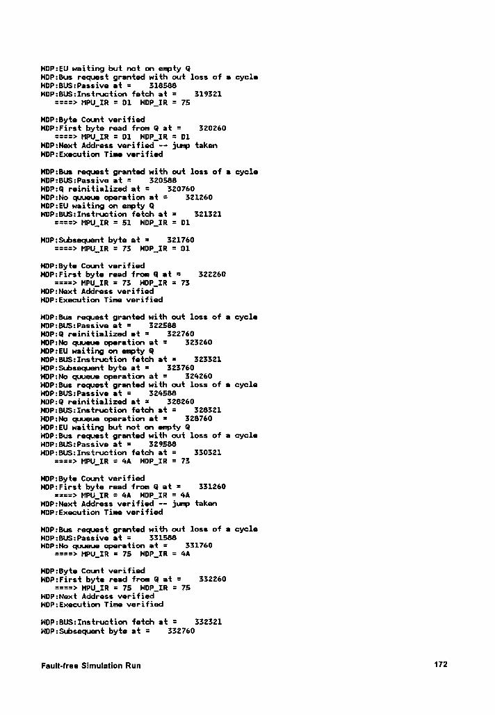
HDP:EU waiting but not on epty QNDP:Bus request granted with out loss of a cycleHDP:BU$:Passive at = 318588NOP:BU$:Instruction fetch at = 319321
====> MPU_IR = D1 l·IDP_IR = 75
NOP:Byte Count verifiedHDP:First byte read from Q at = 320260
====> MPU_IR = D1 HDP_IR = D1NDP:Next Address verified -- junp takenNDP:Execution Time verified
HDP:Bus request granted with out loss of a cycleHDP:BU$:Passive at = 320588HDP:Q reinitialized at = 320760NDP:No quueue operation at = 321260NDP:EU waiting on empty QNDP:BUS:Instruction fetch at = 321321
====> MPU_IR = 51 N¤P_IR = D1
NDP:Sd:»sequent byte at = 321760====> MPU_IR = 73 HDP__IR = D1
HDP:Byte Count verifiedNDP:First byte read from Q at = 322260
====> MPU_IR = 73 NDP_IR = 73HDP:Next Address verifiedNDP:Executin Time verified
HDP:Bus request granted with out loss of a cycleNDP:BUS:Passive at = 322588HDP:Q reinitialized at = 322760HOP:No quueue operation at = 323260NDP:EU waiting on enpty 9NOP:BUS:Instruction fetch at = 323321HDP:$ubsequent byte at = 323760Vl0P:No quueue operation at = 324260HDP:Bus request granted with out loss of a cycleNDP:BU$:Passive at = 324588NDP:Q reinitialized at = 328260HDP:BU$:Instruction fetch at = 328321HDP:No quueue operation at = 328760NDP:EU waiting but not on empty QHDP:Bus request granted with out loss of a cycleNDP:BU$:Passive at = 329588NOP:8U$:Instruction fetch at = 330321
====> MPU_IR = 4A HDP_IR = 73
HDP:Byte Count verifiedNDP:First byte read from Q at = 331260
====> MPU_IR = 4A HDP_IR = 4ANOP:Next Address verified -- jump taknNDP:Execution Time verified
HDP:Bus request granted with out loss of a cycleNOP:BUS:Passive at = 331588NOP:No quueue operation at = 331760
====> MPU_IR = 75 NDP_IR = 4A
NDP:Byte Count verifiedHOP:First byte read from Q at = 332260
====> MPU_IR = 75 NDP_IR = 75NDP:Next Address verifiedHDP:Execution Time verified
HOP:BU$:Instruction fetch at = 332321NOP:$ubsequent byte at = 332760
Fault·lree Simulatlon Run 172
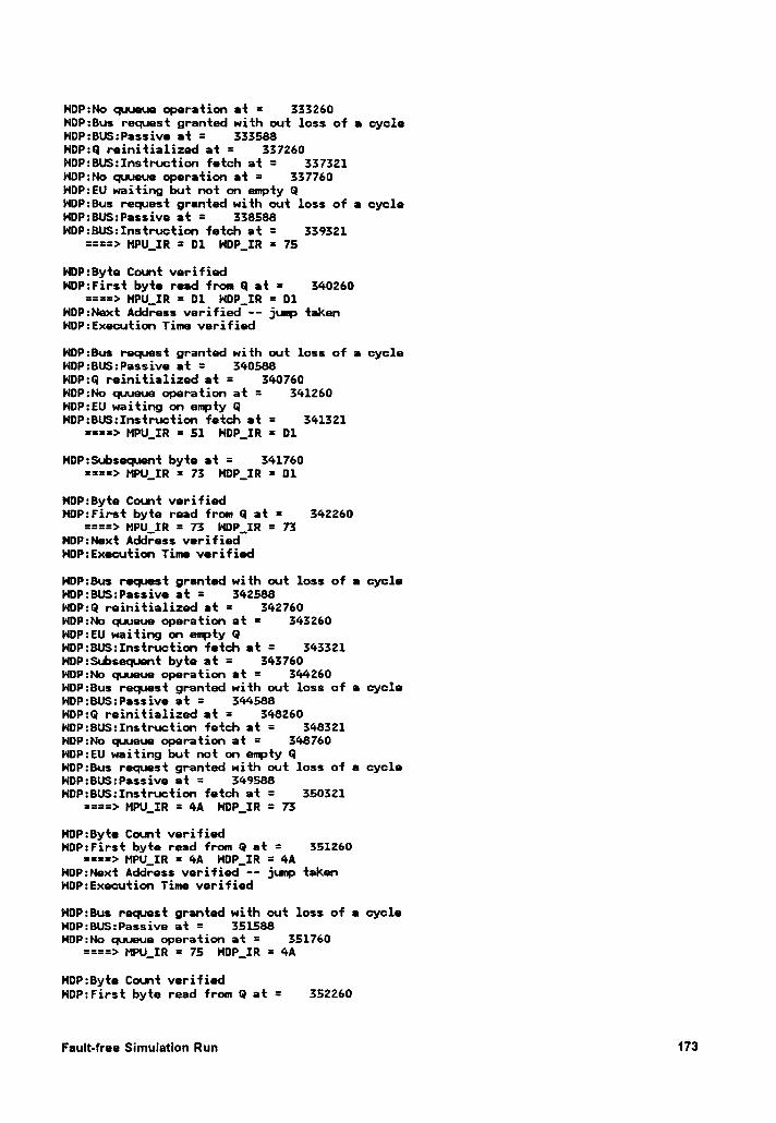
HOP:No quueue operation et = 333260HDP:Bus request granted with out loss of a cycleNOP:BUS:Passive at = 333588HDP:Q reinitialized at = 337260HOP:BU$:Instruction fetch at = 337321HDP:No quueue operation at = 337760NDP:EU waiting but not on empty GHOP:Bus request granted with out loss of a cycleHOP:BU$:Passive at = 338588H¤P:BU$:Instruction fetch at = 339321
====> MPU_IR = D1 HDP_IR = 75
HDP:Byte Count verifiedHDP:First byte read from Q at = 340260
====> MPQ_IR = D1 HDP_IR = D1HDP:Next Address verified ·- jump takenNDP:Execution Time verified
NDP:Bus request granted with out loss of a cycleHOP:BU$:Passive at = 340588HDP:Q reinitialized at = 340760HDP:No quueue operation at = 341260NDP:EU waiting on empty GHDP:BUS:Instruction fetch at = 341321
====> MPU_IR = 51 NDP_IR = D1
NOP:$ubsequnt byte at = 341760====> HPU_IR = 73 HDP_IR = D1
HDP:Byte Count verifiedHDP:First byte read from Q at = 342260
====> MPU_IR = 73 HDP__IR = 73NDP:Next Address verifiedHOP:Execution Time verified
HOP:Bus request granted with out loss of a cycleNDP:BU$:Passive at = 342588HOP:Q reinitialized at = 342760NOP:No quueue operation et = 343260HDP:EU waiting on empty QHDP:BU$:Instruction fetch at = 343321HDP:$ubsequnt byte at = 343760NOP:No quueue operation at = 344260HDP:Bus request granted with out loss of e cycleHDP:BU$:Passive at = 344588HDP:Q reinitialized at = 348260HOP:BUS:Instruction fetch at = 348321NOP:No quueue operation at = 348760NDP:EU waiting but not on empty QNDP:Bus request granted with out loss of a cycleNDP:BUS:Passive at = 349588HDP:BU$:Instruction fetch at = 350321
====> MPU_IR = 4A HDP_IR = 73
HOP:8yte Cont verifiedHDP:First byte read from Q at = 351260
====> MPU_IR = 4A HOP_IR = 4ANDP:Next Address verified -- jump takenHDP:Execution Time verified
NDP:Bus request granted with out loss of e cycleNDP:BU$:Passive at = 351588NDP:No quueue operation at = 351760
====> MPU_IR = 75 NDP_IR = 4A
NOP:Byte Count verifiedNDP:First byte read from Q at = 352260
Fault-free Simulatlon Run 173
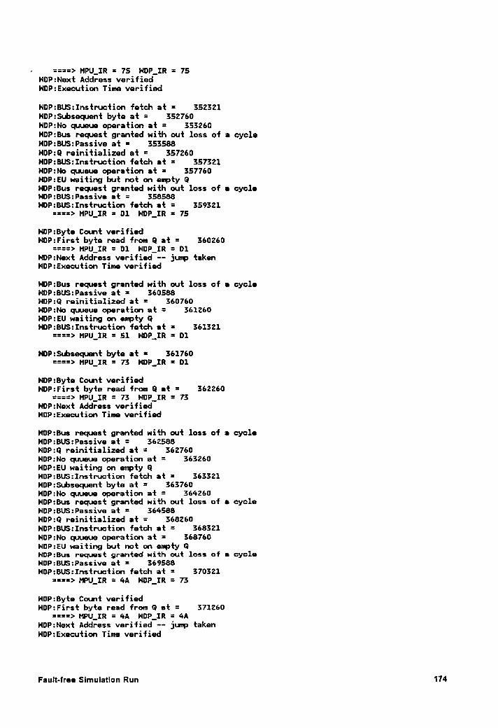
— ====> MPU_IR = 75 HOP_IR = 75NDP:Next Address verifiedHOP:Execution Time verified
NDP:BU$:Instruction fetch at = 352321NDP:$ubsequent byte at = 352760HDP:No quueue operation at = 353260HDP:Bus request granted with out loss of a cycleNDP:BU$:Passive at = 353588HOP:Q reinitialized at = 357260NDP:BU$:Instruction fetch at = 357321NDP:No quueue operation at = 357760HDP:EU waiting but not on empty QNDP:Bus request granted with out loss of e cycleNDP:BU$:Passive at = 358588HDP:BU$:Instruction fetch at = 359321
====> MPU_IR = D1 HDP_IR = 75
HDP:Byte Count verifiedNOP:First byte read from Q at = 360260
====> MPU_IR = D1 NDP_IR = D1NDP:Next Address verified -- jump takenNDP:Execution Time verified
HDP:8us request granted with out loss of e cycleHDP:BUS:Passive at = 360588NOP:Q reinitialized at = 360760HDP:No quueue operation at = 361260HDP:EU waiting on mpty QHDP:BU$:Instruction fetch et = 361321
====> MPU_IR = 51 HDP_IR = D1
HDP:$ubsequnt byte at = 361760====> MPU_IR = 73 HOP_IR = 01
HOP:8yte Count verifiedHDP:First byte read from Q et = 362260
====> MPU_IR = 73 NDP_IR = 73HDP:Next Address verifiedNDP:Execution Time verified
HOP:Bus request granted with out loss of • cycleHDP:BUS:Passive at = 362588NDP:Q reinitialized at = 362760NDP:No quueue operation at = 363260NDP:EU waiting on empty QNOP:BU$:Instruction fetch at = 363321HDP:$ubsquent byte at = 363760NOP:No quueue operation at = 364260HDP:Bus request granted with out loss of a cycleNDP:BU$:Passive at = 364588HDP:Q reinitialized at = 368260HOP:BU$:Instruction fetch at = 368321HDP:No quueue operation at = 368760NDP:EU waiting but not on empty QNDP:Bus request granted with out loss of e cycleHDP:BU$:Passive at = 369588NOP:BU$:Instruction fetch at = 370321
====> HPU_IR = 4A HOP_IR = 73
HDP:Byte Count verifiedNDP:First byte read from Q at = 371260
====> MPU_IR = 4A NDP_IR = 4AHOP:Next Address verified —- jump takenNOP:Execution Time verified
Fault-free Simulation Run 174
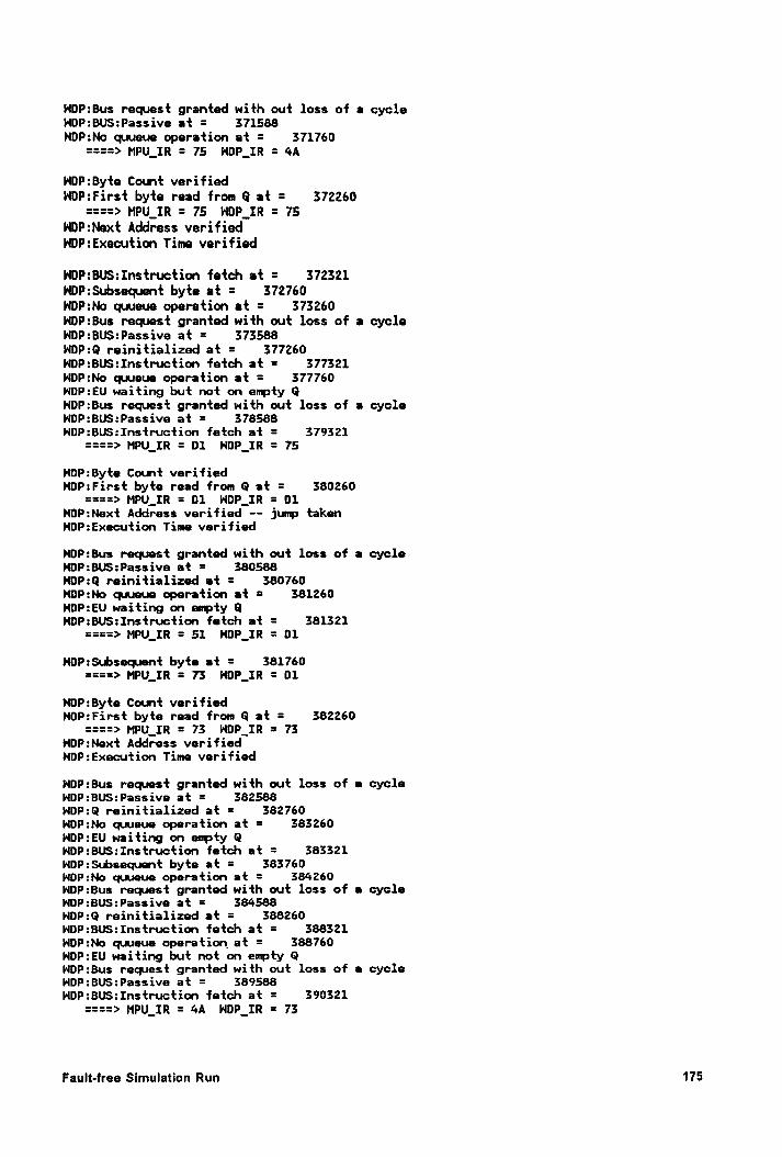
l•lDP:8us request granted with out loss of a cycleNDP:BUS:Passive at = 371588HOP:No quueue operation at = 371760
====> MPU_IR = 75 HDP_IR = 4A
NDP:Byte Count verifiedNDP:First byte read from Q at = 372260
====> MPU_IR = 75 NDP_IR = 75NDP:Next Address verifiedNDP:Execution Time verified
NOP:BUS:Instruction fetch at = 372321NOP:Subsequent byte at = 372760HDP:No quueue operation at = 373260NOP:Bus request granted with out loss of a cycleNOP:BU$:Passive at = 373588HDP:Q reinitialized at = 377260HOP:BU$:Instruction fetch at = 377321HDP:No quueue operation at = 377760NDP:EU waiting but not on enpty QNDP:Bus request granted with out loss of a cycleHOP:BU$:Passive at = 378588HDP:BU$:Instruction fetch at = 379321
====> MPU_IR = 01 HOP_IR = 75
NDP:Byte Count verifiedNDP:First byte read from Q at = 380260
====> MPU_IR = 01 HDP_IR = 01NDP:Next Address verified -- jump takenNDP:Execution Time verified
HDP:8us request granted with out loss of a cycleHOP:BUS:Passive at = 380588NOP:Q reinitialized at = 380760N¤P:No cpueue operation at = 381260NOP:EU waiting on eupty QHDP:BU$:Instruction fetch at = 381321
====> MPU_IR = 51 HDP_IR = 01
HOP:Subsecpent byte at = 381760====> MPU_IR = 73 HOP_IR = D1
NDP:Byte Count verifiedNOP:First byte read from Q at = 382260
====> MPU_IR = 73 NDP_IR = 73HDP:Next Address verifiedHDP:Execution Time verified
NDP:Bus request granted with out loss of a cycleHDP:BUS:Passive at = 382588HDP:Q reinitialized at = 382760HOP:No quueue operation at = 383260NDP:EU waiting on enpty QNOP:BU$:Instruction fetch at = 383321NDP:$ubsequent byte at = 383760NDP:No quueue operation at = 384260HDP:Bus request granted with out loss of a cycleNDP:BUS:Passive at = 384588HDP:Q reinitialized at = 388260NDP:BU$:Instruction fetch at = 388321HDP:No quueue operation at = 388760HDP:EU waiting but not on empty QNDP:Bus request granted with out loss of a cycleNDP:BUS:Passive at = 389588NDP:BUS:Instruction fetch at = 390321
====> MPU_IR = 4A HOP_IR = 73
Fault·lree Slmulatlon Run 175
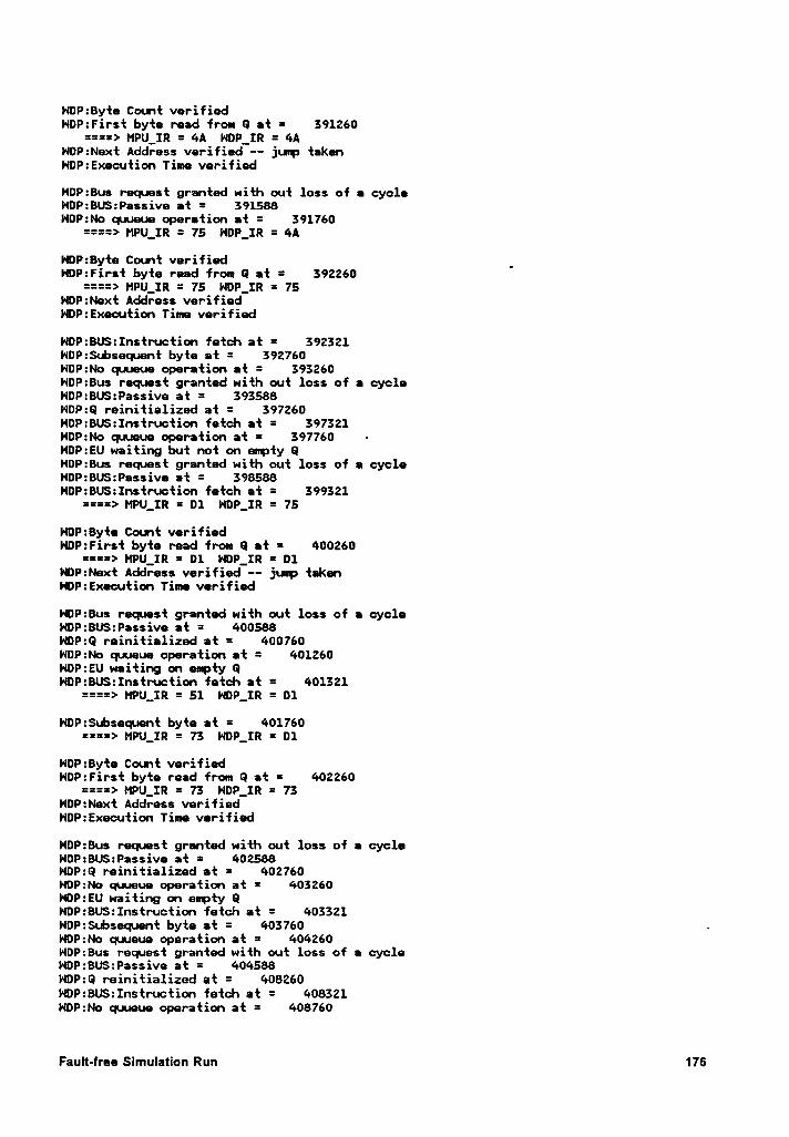
NDP:Byte Count verifiedNDP:First byte read from Q at = 391260
====> MPU_IR = 4A HOP_IR = 4AHDP:Next Address verified —— junp takenNDP:Execution Time verified
NDP:Bus request granted with out loss of a cycleHOP:BUS:Passive at = 391588HDP:No quueue operation at = 391760
====> MPU_IR = 75 HDP_IR = 4A
HDP:Byte Cotnt verified _HDP:First byte read from G at = 392260
====> MPU_IR = 75 NDP_IR = 75NOP:Next Address verifiedNDP:Execution Time verified
NOP:BU$:Instruction fetch at = 392321NDP:$ubsequent byte at = 392760HDP:No quueue operation at = 393260HDP:Bus request granted with out loss of a cycleHDP:BU$:Passive at = 393588HDP:Q reinitialized at = 397260NDP:BUS:Instruction fetch at = 397321HOP:No quueue operation at = 397760 ·NDP:EU waiting but not on enpty GHDP:Bus request granted with out loss of • cycleHDP:BUS:Passive at = 398588NOP:BU$:Instruction fetch at = 399321
====> MPU_IR = D1 HDP_IR = 75
HOP:Byte Count verifiedHOP:First byte read from Q at = 400260
====> HPU_IR = D1 NDP_IR = 01NDP:Next Address verified -- jurp takenHDP:Execution Time verified
NOP:Bus recpest granted with out loss of a cycleNOP:BUS:Passive at = 400588HDP:Q reinitialized at = 400760NDP:No quueue operation at = 401260HDP:EU waiting on empty 0NOP:BU$:Instruction fetch at = 401321
====> MPU_IR = 51 NDP_1R = D1
HDP:Subsequent byte at = 401760====> MPU_IR = 73 NDP_IR = D1
HDP:Byte Count verifiedHOP:First byte read from Q at = 402260
====> MPU_IR = 73 NOP_IR = 73NDP:Next Address verifiedl·lDP:Execution Time verified
NDP:Bus request granted with out loss of a cycleNOP:BUS:Passive at = 402588NOP:Q reinitialized at = 402760HOP:No quueue operation at = 403260HDP:EU waiting on enpty GHOP:BUS:Instruction fetch at = 403321HDP:$Lbsequent byte at = 403760 .l•lDP:No quueue operation at = 404260HOP:Bus request granted with out loss of • cycleHDP:BU$:Passive at = 404588HOP:Q reinitialized at = 408260NDP:BUS:Instruction fetch at = 408321HDP:No quueue operation at = 408760
Fault-free Simulation Run 176
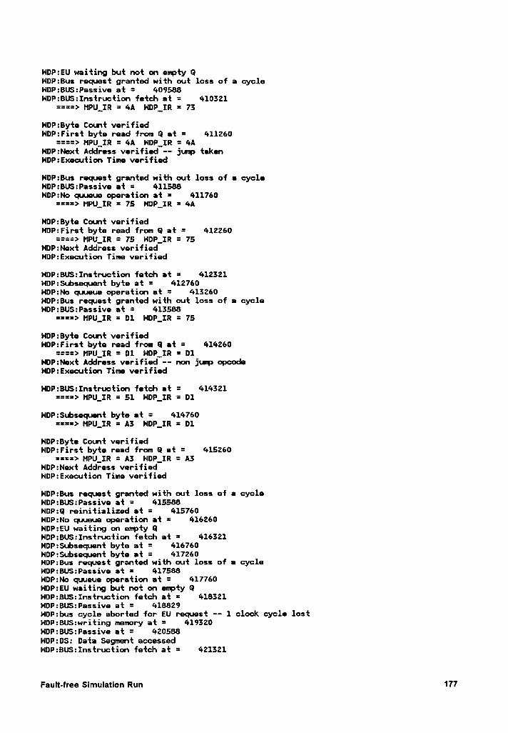
NDP:EU waiting but not on empty QNDP:Bus request granted with out loss of a cycleNDP:BU$:Passive at = 409588NDP:BUS:Instruction fetch at = 410321
====> HPU_IR = 4A HDP_IR = 73
HDP:Byte Count verifiedHDP:First byte read from Q at = 411260
====> MPU_IR = 4A NDP_IR = 4AHDP:Next Address verified —— jump takenNDP:Execution Time verified
NDP:Bus request granted with out loss of a cycleHDP:BUS:Passive at = 411588HDP:No quueue operation at = 411760
====> MPU_IR = 75 NDP_IR = 4A
HOP:Byte Count verifiedHDP:First byte read from Q at = 412260
====> MPU_IR = 75 NDP_IR = 75NDP:Next Address verifiedHDP:Execution Time verified
NDP:BU$:Instruction fetch at = 412321HDP:Subsequnt byte at = 412760NDP:No quueue operation at = 413260NDP:Bus request granted with out loss of a cycleHDP:BU$:Passive at = 413588
====> MPU_IR = D1 NDP_IR = 75
HDP:Byte Count verifiedNDP:First byte read from Q at = 414260
====> HPU_IR = 01 NOP_IR = D1NDP:Next Address verified -— non jump opcodeHDP:Execution Time verified
NDP:BUS:Instruction fetch at = 414321====> MPU_IR = 51 NDP_IR = D1
NDP:Snbsequent byte at = 414760====> MPU_IR = A3 HDP_IR = D1
HDP:Byte Count verifiedNDP:First byte read from Q at = 415260
====> MPU_IR = A3 NOP_IR = A3NDP:Next Address verifiedNDP:Execution Time verified
NDP:Bus request granted with out loss of a cycleHDP:BU$:Passive at = 415588HDP:Q reinitialized at = 415760HDP:No quueue operation at = 416260HDP:EU waiting on empty QNDP:BU$:Instruction fetch at = 416321NDP:$ubsequent byte at = 416760HDP:Subsequnt byte at = 417260HDP:Bus request granted with out loss of a cycleNDP:8US:Passive at = 417588NDP:No quueue operation at = 417760NDP:EU waiting but not on empty QNDP:BU$:Instruction fetch at = 418321NDP:BU$:Passive at = 418829HDP:bus cycle aborted for EU request —· 1 clock cycle lostHDP:BU$:writing memory at = 419320NDP:BU$:Passive at = 420588NDP:0S: Data Segmnt accessedNDP:BUS:Instruction fetch at = 421321
Fault-free Simulation Run 177
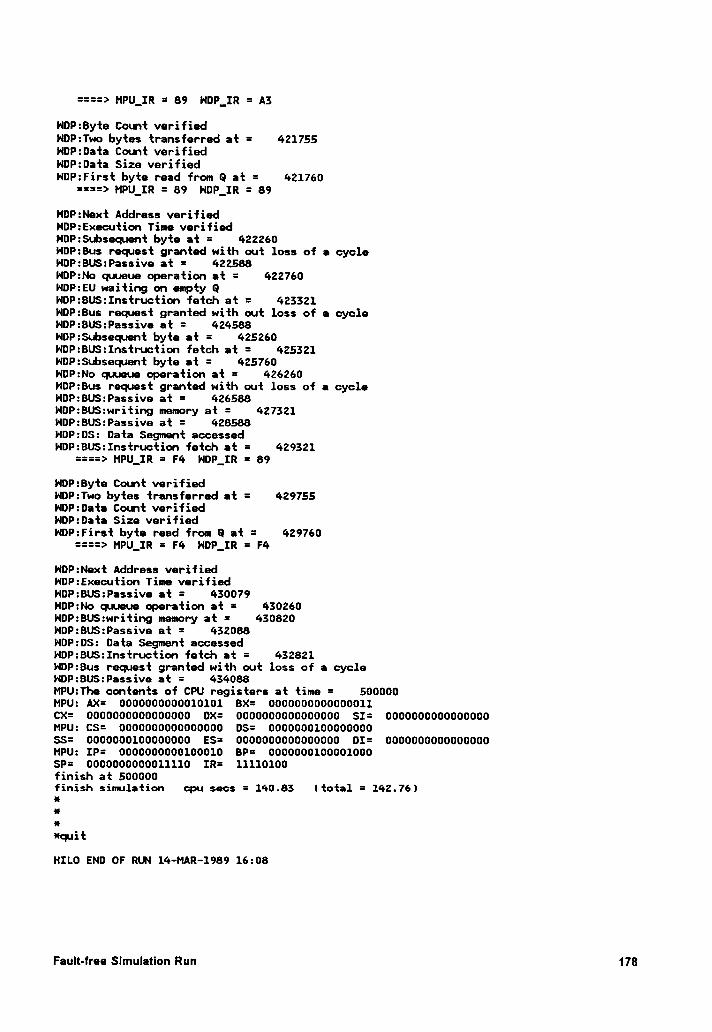
====> MPU_IR = 89 H¤P_IR = A3
HDP:Byte Count verifiedHDP:Two bytes transferred at = 421755HDP:Data Count verifiedNDP:Data Size verifiedNDP:First byte read from Q at = 421760
====> MPU_IR = 89 HDP_IR = 89
HDP:Next Address verifiedHDP:Execution Time verifiedNDP:Subsequent byte at = 422260HDP:Bus request granted with out loss of a cycleHDP:BUS:Passive at = 422588NOP:No quueue operation at = 422760HDP:EU waiting on epty 0HOP:BUS:Instruction fetch at = 423321NDP:Bus request granted with out loss of e cycleNDP:BUS:Passive at = 424588NDP:Subsequent byte at = 425260NDP:BU$:Instruction fetch at = 425321NDP:Subsequent byte at = 425760NDP:No quueue operation at = 426260NDP:Bus request granted with out loss of a cycleHDP:BUS:Passive at = 426588NDP:BUS:writing mmory at = 427321HDP:BU$:Passive at = 428588HDP:0S: Data Segmnt accessedHDP:BU$:Instruction fetch at = 429321
====> MPU_IR = F4 HDP_IR = 89
HDP:Byte Count verifiedHDP:Two bytes transferred at = 429755HDP:Data Count verifiedHDP:Data Size verifiedNDP:First byte read from Q at = 429760
====> MPU_IR = F4 HDP_IR = F4
NDP:Next Address verifiedNDP:Execution Time verifiedHDP:BUS:Passive at = 430079HDP:No quueue operation at = 430260HDP:BU$:writing memory at = 430820NDP:BUS:Passive at = 432088NDP:DS: Data Segment accessedNDP:BU$:Instruction fetch at = 432821NDP:Bus request granted with out loss of a cycleNDP:BUS:Passive at = 434088MPU:The contents of CPU registers at time = 500000MPU: AX= 0000000000010101 BX= 0000000000000011CX= 0000000000000000 DX= 0000000000000000 SI= 0000000000000000MPU: CS= 0000000000000000 DS= 0000000100000000SS= 0000000100000000 ES= 0000000000000000 DI= 0000000000000000MPU: IP= 0000000000100010 BP= 0000000100001000SP= 0000000000011110 IR= 11110100finish at 500000finish simulation cpu secs = 140.83 (total = 142.76)xxx*quit
HILO END OF RUN 14-MAR-1989 16:08
Fault-free Simulation Run 178
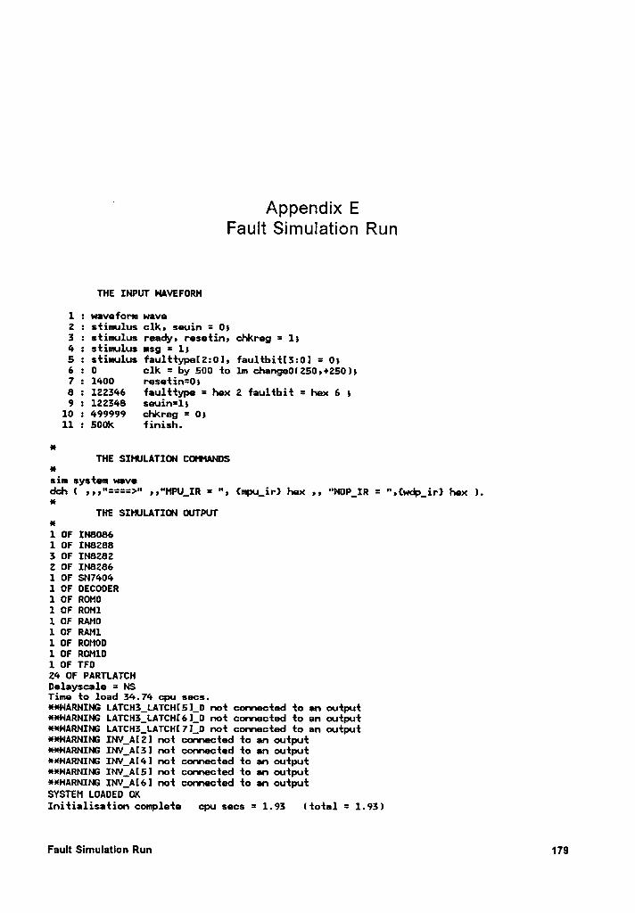
Appendxx EFauItS¤mu|at10n Run
THE INPUT NAVEFORM
1 : wavefom wave2 : sfimulus clk, seuin = 053 : stimulus ready, resefin; chkreg = 154 : siimulus msg = 155 : sfimulus faul‘I:*l:ypel2:0]5 faulfbi.fl3:Ol = 056 : O clk = by 500 to 1m changeOl250,+250)57 : 1400 r~esel:in=058 : 122346 faulffype = hex 2 faulibit = hex 6 59 : 122348 seuin=15
10 : 499999 chkreg = 0511 : 500k finish.
esTHE SINJLATIG1 COYMANOS
alsin system wavedch ( n•"====>" n"MPU__IR = ", {mpu_ir} hex ,5 "NDP_IR = '°,(wc#>_ir} hex l.x
THE SIHJLATION OUTPUTan1 OF INB0861 OF IN82883 OF IN82822 OF IN82861 OF SN74041 OF DECODER1 OF ROM01 OF ROMI1 OF RAM01 OF RAM11 OF ROMOO1 OF ROM101 OF TFD24 OF PARTLATCHDelayscale = NSTime fo load 34.74 cpu secs.**NARNING LATCH3_LATCHI5]_D nof connecfed fo an oufpuf·¤*HARNING LATCH3_LATCH(6]_O no‘|: cornacted fo an output 5HNARNING LATCH3_LATCH[7]_D not connected to an outpufHNARNING INV_AI2] not connected {o an oufpui:HNARNING INV_A[3] not connecfed fo an output·¤·¤·HARNING INV_A[4] noi connected fo an ouipuf**HARNING INV_Al5l not connected to an ouiput**HARNING INV_A[6] no‘l: connecied fo an oufpufSYSTEM LOADED OKInifialisafion covnplefe cpu secs = 1.93 lfofal = 1.93)
Fault Slmulatlon Run 179
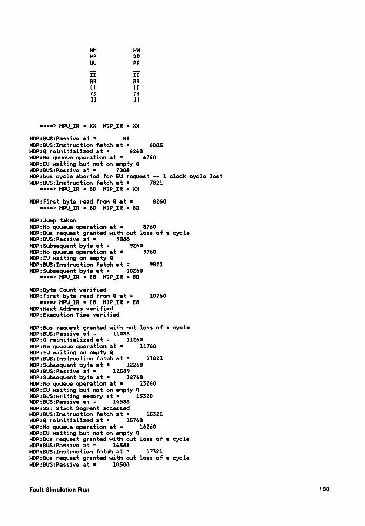
M HHPP DDUU PP
II IIRR RR[I ll73 73ll 1]
====> MPU__IR = XX HDP_IR = XX
NOP:BU:Pessive at = 80HDP:BUS:Instruction fetch et = 6085NDP:Q reinitialized at = 6260NOP:No quueue operation at = 6760HDP:EU waiting but not on empty QHOP:BUS:Passive at = 7088NDP:bus cycle aborted for EU request ·- 1 clock cycle lostNDP:BUS:Instruction fetch at = 7821
====> MPU_IR = B0 HDP_IR = Xx
NOP:First byte read from Q at = 8260====> MPU_IR = BD HOP__IR
= BD
HDP:Jump takenNDP:No quueue operation at = 8760NDP:Bus request granted with out loss of e cycleHOP:BUS:Passive at = 9088NOP:Subsequent byte at = 9260WOP:No quueue operation at = 9760NDP:EU waiting on mpty GHOP:BU$:Instruction fetch et = 9821NDP:$ubsequet byte at = 10260
====> MPU_IR = E8 HDP__IR = BD
NOP:Byte Count verifiedN¤P:First byte read from Q at = 10760
====> MPU_IR = E8 NOP_IR = E8HDP:Next Address verifiedNOP:Execution Time verified
NDP:Bus request granted with out loss of e cycleNOP:BUS:Passive at = 11088HOP:Q reinitialized at = 11260NOP:No quueue operation at = 11760NDP:EU waiting on empty GNDP:BUS:Instruction fetch at = 11821HDP:Subsequent byte at = 12260NOP:BUS:Passive at = 12589HDP:Subsequent byte at = 12760NOP:No quueue operation at = 13260NOP:EU waiting but not on empty 0HOP:BUS:writing memory at = 13320NDP:BU$:Passive at = 14588 _NDP:SS: Stack Segment accessedHOP:BU$:Instruction fetch at = 15321NDP:Q reinitialized at = 15760HDP:No quueue operation at = 16260NDP:EU waiting but not on empty 0NDP:Bus request granted with out loss of a cycleHDP:BU$:Passive at = 16588HDP:BUS:Instruction fetch at = 17321NDP:Bus request granted with out loss of a cycleNOP:BUS:Passive at = 18588
Fault Slmulatlon Run 180
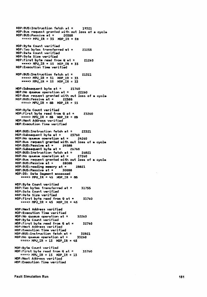
HDP:BUS:Instruction fetch at = 19321HDP:Bus request granted with out loss of a cycleHDP:BUS:Passive at = 20588
====> MPU_IR = 33 NDP_IR = E8
NDP:8yte Count verifiedHDP:Two bytes transferred at = 21255HDP:Data Count verifiedNDP:Data Size verifiedHOP:First byte read from Q at = 21260
====> MPU_IR = 33 H¤P_IR = 33NDP:Execution Time verified
HDP:8US:Instruction fetch at = 21321====> MPU_IR = 31 NDP_IR = 33====> MPU_IR = 33 NDP_IR = 33
NDP:S«.bsequent byte et = 21760HDP:No quueue operation at = 22260HDP:8us request granted with out loss of e cycleNDP:BUS:Passive at = 22588
====> MPU_IR = 88 HDP_IR = 33
NDP:Byte Count verifiedNDP:First byte read from Q at = 23260
====> MPU_IR = 88 HDP_IR = 88NDP:Next Address verifiedHDP:Execution Time verified
HDP:BUS:Instruction fetch at = 23321NDP:Subsequent byte at = 23760HDP:No quueue operation et = 24260HDP:8us request granted with out loss of • cycleNDP:BUS:Passive et = 24588NDP:Subsequet byte at = 26760HOP:BUS:Instruction fetch at = 26821NDP:No quueue operation et = 27260HDP:8us request granted with out loss of a cycleNDP:BU$:Passive at = 28088NDP:8US:reading memory at = 28821HDP:8US:Passive at = 30088HDP:DS: Data Segment eccessed
====> MPU_IR = 45 NDP_IR = 88
HOP:Byte Count verifiedNDP:Two bytes transferred at = 31755NDP:0ata Count verifiedHDP:Data Size verifiedHDP:First byte read from Q at = 31760
====> MPU_IR = 45 HOP_IR = 45
HDP:Next Address verifiedHDP:Execution Time verifiedNDP:No quueue operation at = 32260HDP:8yte Count verifiedNDP:First byte read from Q at = 32760N¤P:Next Address verifiedHDP:Execution Time verifiedHDP:8US:Instruction fetch at = 32821HDP:No quueue operation at = 33260
====> MPU_IR = 13 HDP_IR = 45
NDP:Byte Count verifiedHDP:First byte read from Q at = 33760
====> MPU_IR = 13 NDP_IR = 13NDP:Next Address verifiedNDP:Execution Time verified
Fault Simulation Run 181
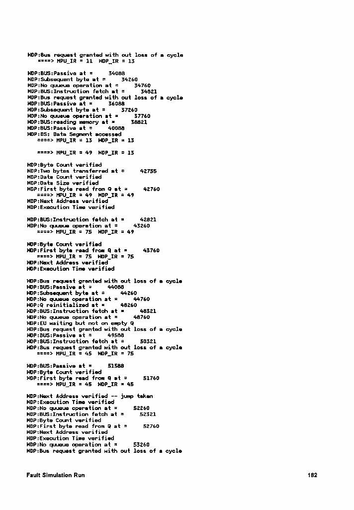
NDP:Bus request granted with out loss of a cycle====> MPU_IR = 11 NDP_IR = 13
HDP:BU$:Passive at = 34088HDP:$ubsequnt byte at = 34260NOP:No quueue operation at = 34760NDP:BUS:Instruction fetch at = 34821HOP:Bus request granted with out loss of a cycleHDP:BUS:Passive at = 36088NDP:Subsequent byte at = 37260NDP:No quueue operation at = 37760HDP:BUS:reading memory et = 38821NDP:BU$:Passive at = 40088NOP:DS: Data Segment accessed
====> MPU_IR = 13 NDP_IR = 13
====> MPU_IR = 49 HOP_IR = 13
HDP:Byte Count verifiedHDP:Two bytes transferred at = 42755HOP:Data Count verifiedNDP:Data Size verifiedNDP:First byte read from Q et = 42760
====> MPU_IR = 49 NDP_IR = 49NOP:Next Address verifiedNDP:Execution Time verified
HOP:BUS:Instruction fetch at = 42821HDP:No quueue operation at = 43260
====> HPU_IR = 75 HOP_IR = 49
HDP:Byte Count verifiedNDP:First byte read from Q at = 43760
====> MPU_IR = 75 NDP_IR = 75NDP:Next Address verifiedNDP:Execution Time verified
NOP:Bus request granted with out loss of a cycleNDP:BU$:Passive at = 44088NOP:Subsequnt byte at = 44260HDP:No quueue operation at = 44760HOP:Q reinitialized at = 48260HDP:BUS:Instruction fetch at = 48321NDP:No quueue operation at = 48760NDP:EU waiting but not on empty GNDP:Bus request granted with out loss of a cycleHDP:8U$:Passive at = 49588NOP:BUS:Instruction fetch at = 50321HDP:Bus request granted with out loss of a cycle
====> MPU_IR = 45 NDP_IR = 75
HOP:BUS:Passive et = 51588NDP:Byte Count verifiedNDP:First byte read from Q at = 51760
====> MPU_IR = 45 NDP_IR = 45
HOP:Next Address verified -- jump takenNOP:Execution Time verifiedHDP:No quueue operation at = 52260HOP:BU$:Instruction fetch at = 52321NDP:Byte Count verifiedNDP:First byte read from 0 at = 52760NOP:Next Address verifiedNDP:Execution Time verifiedHDP:No quueue operation at = 53260HDP:Bus request granted with out loss of a cycle
Fault Simulation Run 182
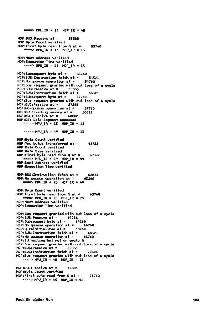
====> MPU_IR = 13 HOP_IR = 45
NOP:BUS:Passive at = 53588HOP:Byte Count verifiedHOP:First byte read from Q at = 53760
====> MPU_IR = 13 HDP_IR = 13
HDP:Next Address verifiedNOP:Execution Time verified
====> MPU_IR = 11 NDP_IR = 13
NDP:$~.bsequent byte at = 54260HOP:BUS:Instruction fetch at = 54321HDP:No quueue operation at = 54760NOP:Bus request granted with out loss of a cycleNDP:BUS:Passiv• at = 55588HOP:BUS:Instru•ction fetch at = 56321NOP:$ubsequent byte at = 57260NDP:Bus request granted with out loss of a cycleHDP:BUS:Passive at = 57588HDP:No-cpueue operation at = 57760NOP:BUS:reading memory at = 58821HDP:BU$:Passive at = 60088NOP:D$: Data Segnent accessed
====> MPU_IR = 13 HDP_IR = 13
====> MPU_IR = 49 NOP_IR = 13
NOP:Byte Count verifiedHDP:Two bytes transferred at = 62755NOP:0ata Count verifiedNDP:0ata Size verifiedNOP:First byte read from Q et = 62760
====> MPU__IR = 49 HOP_IR = 49NOP:Next Address verifiedHDP:Execution Time verified
NOP:BUS:Instruction fetch at = 62821HOP:No quueue operation at = 63260
====> MPU_IR = 75 HOP_IR = 49
NDP:Byte Count verifiedNOP:First byte read from Q at = 63760
====> MPU_IR = 75 NDP_IR = 75HOP:Next Address verifiedHDP:Execution Time verified
NOP:Bus request granted with out loss of a cycleHOP:BUS:Passive at = 64088HOP:$ubsequent byte at = 64260NOP:No queue operation at = 64760NOP:Q reinitialized at = 68260HOP:BU$:Instruction fetch at = 68321NDP:No quueue operation at = 68760NOP:EU waiting but not on empty 0NOP:Bus request granted with out loss of a cycleHDP:BU$:Passive at = 69588NDP:BUS:Instruction fetch at = 70321HDP:Bus request granted with out loss of a cycle
====> MPU_IR = 45 HDP_IR = 75
HOP:BUS:Passive at = 71588NDP:Byte Count verifiedNDP:First byte read from Q at = 71760
====> MPU_IR = 45 NDP_IR = 45
Fault Slmulatlon Run 183
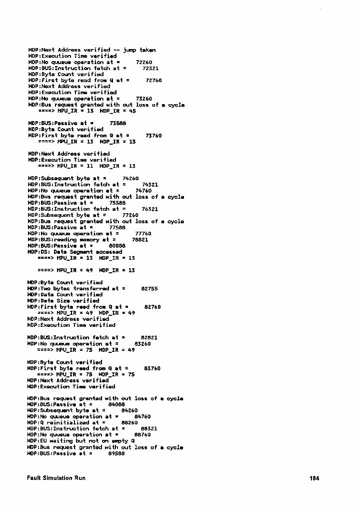
NDP:Next Address verified -- jump taknNOP:Execution Time verifiedNDP:No quueue operation at = 72260NDP:BUS:Instruction fetch at = 72321NDP:Byte Count verifiedNDP:First byte read from Q at = 72760NDP:Next Address verifiedNOP:Execution Time verifiedNOP:No quueue operation at = 73260NDP:Bus request granted with out loss of a cycle
====> MPU_IR = 13 NOP_IR = 45
HDP:BUS:Pessive at = 73588NDP:Byte Count verifiedHOP:First byte read from Q at = 73760
====> MPU_IR = 13 HDP_IR = 13
HOP:Next Address verifiedNDP:Execution Time verified
====> MPU_IR = 11 HDP_IR = 13
NDP:Subsequent byte et = 74260NDP:BUS:Instruction fetch at = 74321NDP:No quueue operation at = 74760HDP:Bus request granted with out loss of a cycleNDP:BUS:Passive at = 75588NOP:BUS:Instruction fetch at = 76321NDP:Subsequent byte at = 77260NDP:Bus request granted with out loss of e cycleNDP:BUS:Passive at = 77588HOP:No quueue operation at = 77760NOP:BUS:reading memory et = 78821HOP:BU$:Passive et = 800880P:0S: Data Segment accessed
====> MPU_IR = 13 HDP_IR = 13
====> MPU_IR = 49 HOP_IR = 13
NDP:8yte Count verifiedNOP:Two bytes transferred at = 82755HDP:Data Count verifiedNDP:Data Size verifiedHOP:First byte read from Q et = 82760
====> MPU_IR = 49 NDP_IR = 49NOP:Next Address verifiedHOP:Execution Time verified
NOP:BU:Instruction fetch at = 82821NDP:No quueue operation at = 83260
====> MPU_IR = 75 HDP_IR = 49
HDP:Byte Count verifiedHDP:First byte read from Q at = 83760
====> MPU_IR = 75 HOP_IR = 75HOP:Next Address verifiedHOP:Execution Time verified
NDP:Bus request granted with out loss of e cycleHOP:BUS:Passive at = 84088HOP:Subsequent byte at = 84260HOP:No quueue operation at = 84760NOP:Q reinitialized at = 88260HOP:BUS:Instruction fetch at = 88321NDP:No quueue operation at = 88760NDP:EU waiting but not on empty QHOP:Bus request granted with out loss of a cycleHOP:BUS:Passive at = 89588
Fault Simulation Run 184
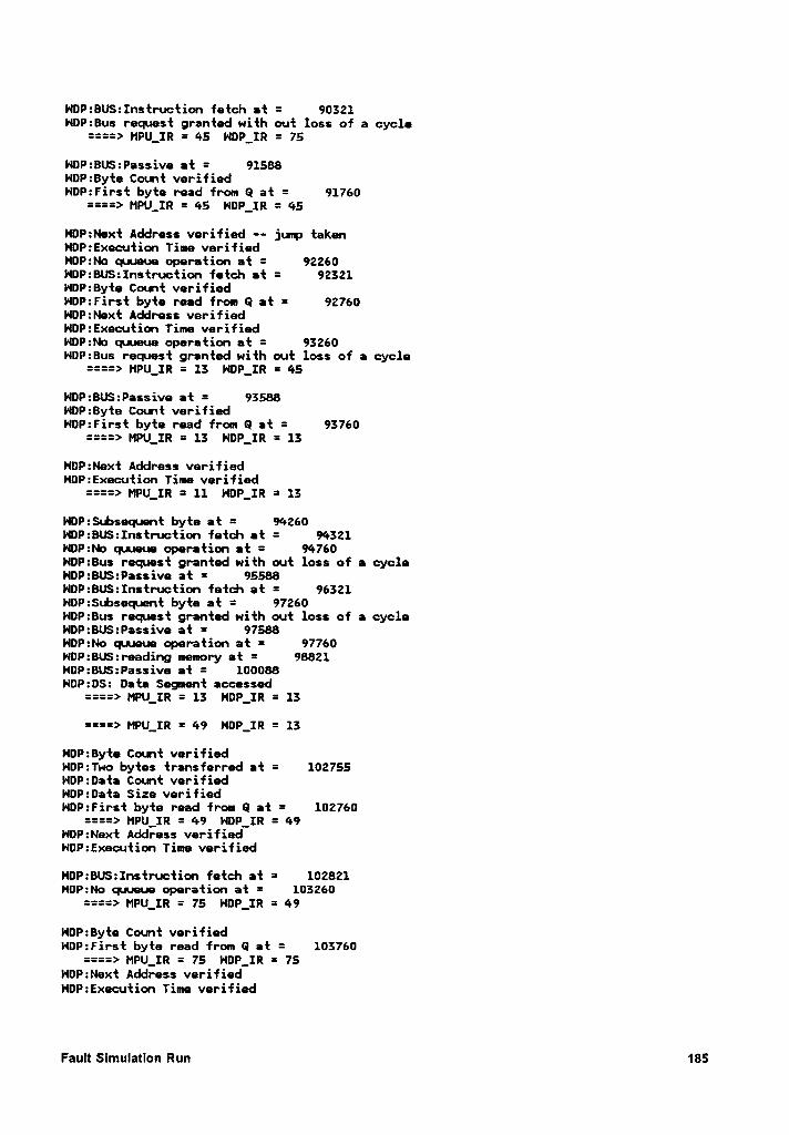
NDP:BUS:Instruction fetch at = 90321HDP:Bus request granted with out loss of a cycle
====> MPU_IR = 45 HDP_IR = 75
NDP=BUS:Passive at = 91588NOP:Byte Count verifiedNDP:First byte read from Q at = 91760
====> MPU_IR = 45 NDP_IR = 45
HDP:Next Address verified —— jump takenHDP:Execution Time verifiedHDP:No quueue operation at = 92260NDP:BUS:Instruction fetch et = 92321NDP:Byte Count verifiedNDP:First byte read from Q at = 92760HOP:Next Address verifiedNOP:Execution Time verifiedHOP:No quueue operation at = 93260NDP:Bus request granted with out loss of a cycle
====> MPU_IR = 13 HDP_IR = 45
NDP:BUS:Passive at = 93588HDP:Byte Count verifiedHDP:First byte read from Q at = 93760
====> MPU_IR = 13 NDP_IR = 13
NOP:Next Address verifiedNDP:Execution Time verified
====> MPU_IR = 11 NDP_IR = 13
HDP:$ubsequent byte at = 94260HDP:BUS:Instruction fetch at = 94321
0P:No quueue operation at = 94760NDP:Bus request granted with out loss of • cycleNDP:BUS:Passive at = 95588HDP:BUS:Instruction fetch at = 96321HDP:Subsequent byte at = 97260NOP:Bus request granted with out loss of a cycleNDP:BU:Passive at = 97588NDP:No quueue operation at = 97760NOP:BUS:reading memory at = 98821HDP:BUS:Passive et = 100088HDP:0S: Data Segmnt accessed
====> MPU_IR = 13 HOP_IR = 13
====> MPU_IR = 49 H¤P_IR = 13
HDP:Byte Count verifiedHDP:Two bytes transferred at = 102755NDP:Data Count verifiedHDP:Data Size verifiedHOP:First byte read from Q at = 102760
====> MPU_IR = 49 H¤P_IR = 49HDP:Next Address verifiedHDP:Execution Time verified
NDP:BUS:Instruction fetch at = 102821HDP:No quueue operation at = 103260
====> MPU_IR = 75 NDP_IR = 49
NOP:Byte Count verifiedHOP:First byte read from Q at = 103760
====> MPU_IR = 75 HDP_IR = 75HOP:Next Address verifiedNDP:Execution Time verified
Fault Slmulatlon Run 185
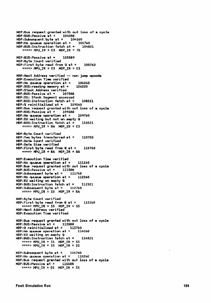
HOP:Bus request granted with out loss of a cycleNDP:BU$:Passive at = 104088NDP:$ubsequent byte at = 104260NDP:No quueue operation at = 104760HDP:BUS:Instruction fetch at = 104821
====> MPU_IR = C3 NOP_IR = 75
HDP:BU$:Passive et = 105589NOP:Byte Count verifiedNDP:First byte read from Q at = 105760
====> MPU_IR = C3 HDP_IR = C3
NDP:Next Address verified -- non jump opcodeHDP:Execution Time verifiedNDP:No quueue operation at = 106260NDP:BUS:reading memory at = 106320NDP:$tack Address verifiedHDP:BUS:Passive et = 107588NDP:$$: Stack Sement accessedNOP:BUS:Instruction fetch at = 108321NOP:Q reinitialized at = 109260HDP:Bus request granted with out loss of e cycleNDP:BUS:Passive at = 109588NDP:No quueue operation at = 109760HDP:EU waiting but not on empty GNDP:BU$:Instruction fetch at = 110321
====> MPU_IR = BA NOP_IR = C3
NDP:Byte Count verifiedHDP:Two bytes transferred at = 110755NDP:Data Count verifiedHDP:Data Size verifiedHDP:First byte read from Q at = 110760
====> MPU_IR = BA HOP_IR = BA
HDP:Execution Time verifiedHDP:No quueue operation at = 111260NDP:Bus request granted with out loss of e cycleNDP:BU$:Passive at = 111588HDP:Subsequent byte at = 111760NOP:No quueue operation at = 112260HOP:EU waiting on empty GNDP:BUS:Instruction fetch at = 112321HOP:Subsequent byte at = 112760
====> MPU_IR = 33 NDP_IR = BA
HDP:Byte Count verifiedNDP:First byte read from Q at = 113260
====> MPU_IR = 33 NDP_IR = 33NDP:Next Address verifiedNDP:Execution Time verified
NDP:Bus request granted with out loss of a cycleHOP:BUS:Passive at = 113588HOP:Q reinitialized at = 113760NDP:No quueue operation at = 114260NDP:EU waiting on empty GNDP:BUS:Instruction fetch at = 114321
====> MPU_IR = 31 HDP_IR = 33====> MPU_IR = 33 HDP_IR = 33
HDP:$ubsequnt byte at = 114760NOP:No quueue operation at = 115260HOP:Bus request granted with out loss of a cycleNDP:BUS:Passive at = 115588
====> MPU_IR = 01 NDP_IR = 33
Fault Slmulatlon Run 186
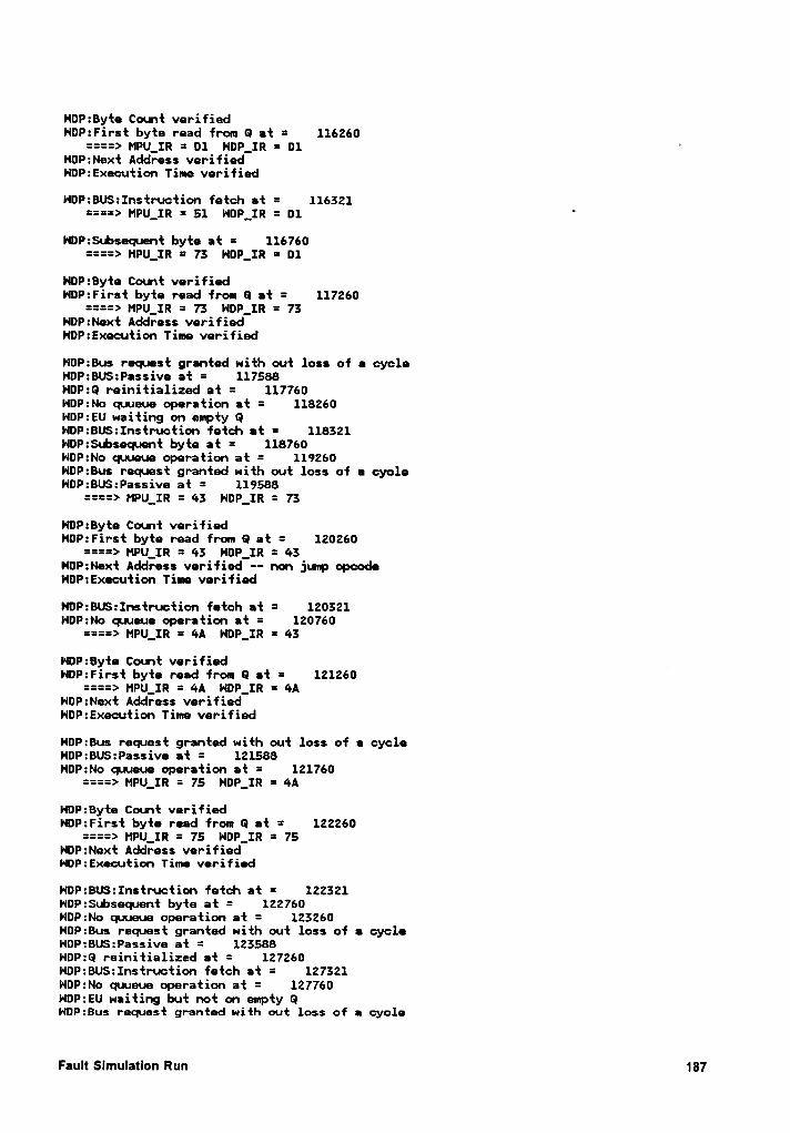
HDP:Byte Count verifiedNOP:First byte read from 0 at = 116260
====> MPU_IR = D1 NDP_IR = 01 'HDP:Next Address verifiedNDP:Execution Time verified
HDP:BUS:Instruction fetch at = 116321====> MPU_IR = 51 HDP_IR = D1
‘
HDP:Subsequnt byte at = 116760====> MPU_IR = 73 HDP_IR = D1
HDP:Byte Count verifiedHDP:First byte read from 0 et = 117260
====> MPU_IR = 73 HDP_IR = 73HOP:Next Address verifiedHDP:Execution Time verified
HOP:Bus request granted with out loss of e cycleHDP:BUS:Passive at = 117588NDP:Q reinitialized at = 117760HDP:No quueue operation at = 118260HDP:EU waiting on empty QHOP:BUS:Instruction fetch et = 118321HOP:Subsequnt byte at = 118760NDP:No quueue operation at = 119260NOP:Bus request granted with out loss of a cycleNDP:BUS:Passive at = 119588
====> MPU_IR = 43 HDP_IR = 73
NOP:Byte Count verifiedHDP:First byte read from Q at = 120260
====> HPU_IR = 43 HDP_IR = 43HDP:Next Address verified -- non jump opcodeHOP:Execution Time verified
NDP:BUS:Instruction fetch at = 120321HDP:No quueue operation at = 120760
====> MPU_IR = 4A NDP_IR = 43
HDP:8yte Count verifiedHDP:First byte read from Q at = 121260
====> MPU_IR = 4A NDP_IR = 4ANDP:Next Address verifiedHOP:Execution Time verified
NDP:Bus request granted with out loss of • cycleHDP:BUS:Passive at = 121588NOP:No quueue operation at = 121760
====> MPU_IR = 75 HDP_IR = 4A
HDP:Byte Count verifiedHDP:First byte read from Q at = 122260
====> MPU_IR = 75 NDP_IR = 75NDP:Next Address verifiedNOP:Execution Time verified
NDP:BU$:Instruction fetch at = 122321HDP:$ubsequnt byte at = 122760NDP:No quueue operation at = 123260NDP:Bus request granted with out loss of a cycleNDP:BU$:Passive at = 123588HDP:0 reinitialized at = 127260NDP:BUS:Instruction fetch at = 127321HDP:No quueue operation at = 127760HDP:EU waiting but not on empty QNDP:Bus request granted with out loss of a cycle
Fault Slmulation Run 181
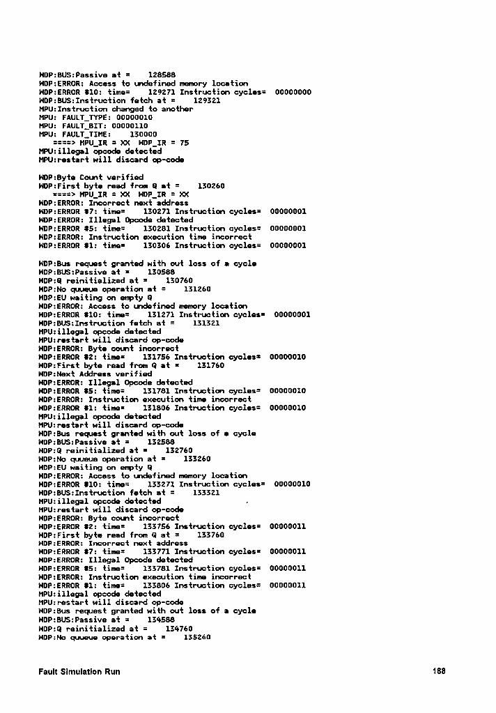
HDP:BUS:Passive at = 128588HDP:ERROR: Access to undefined memory locationHDP:ERROR #10: time= 129271 Instruction cycles= 00000000NDP:BU$:Instruction fetch at = 129321MPU:Instruction changed to anotherMPU: FAULT_TYPE: 00000010MPU: FAULT_BIT: 00000110MPU: FAULT_TIME: 130000
====> MPU_IR = XX NDP_IR = 75MPU:illegal opcode detectedMPU:restart will discard op-code
HDP:8yte Count verifiedNDP:First byte read from Q at = 130260
====> MPU_IR = XX NDP_IR = XXHDP:ERROR: Incorrect next addressNDP:ERROR #7: time= 130271 Instruction cycles= 00000001HDP:ERROR: Illegal Opcode detectedNDP:ERROR #5: time= 130281 Instruction cycles= 00000001HDP:ERROR: Instruction execution time incorrectNOP:ERROR #1: time= 130306 Instruction cycles= 00000001
NDP:Bus request granted with out loss of a cycleHDP:BU$:Passive at = 130588NDP:Q reinitialized et = 130760HDP:No quueue operation at = 131260HDP:EU waiting on empty 0NDP:ERROR: Access to undefined memory locationNDP:ERROR #10: time= 131271 Instruction cycles= 00000001NDP:BU$:Instruction fetch at = 131321MPU:illegal opcode detectedMPU:restart will discard op-codeNDP:ERROR: Byte count incorrectNDP:ERROR #2: time= 131756 Instruction cycles= 00000010NDP:First byte read from Q at = 131760HDP:Next Address verifiedHOP:ERROR: Illegal Opcode detectedNDP:ERROR #5: time= 131781 Instruction cycles= 00000010NDP:ERROR: Instruction execution time incorrectHDP:ERROR #1: time= 131806 Instruction cycles= 00000010MPU:illegal opcode detectedMPU:restart will discard op-codeHOP:Bus request granted with out loss of a cycleNDP:BUS:Passive at = 132588NDP:Q reinitialized at = 132760NDP:No quueue operation at = 133260HDP:EU waiting on empty 0HDP:ERROR: Access to undefined memory locationNDP:ERROR #10: time= 133271 Instruction cycles= 00000010NDP:BU$:Instruction fetch at = 133321MPU:illegal opcode detected ,MPU:restart will discard op-codeNOP:ERROR: Byte count incorrectNDP:ERROR #2: time= 133756 Instruction cycles= 00000011NDP:First byte read from Q at = 133760NDP:ERROR: Incorrect next addressHDP:ERROR #7: time= 133771 Instruction cycles= 00000011HDP:ERROR: Illegal Opcode detectedNDP:ERROR #5: time= 133781 Instruction cycles= 00000011HDP:ERROR: Instruction execution time incorrectHDP:ERROR #1: time= 133806 Instruction cycles= 00000011MPU:illegal opcode detectedMPU:restart will discard op-codeNDP:Bus request granted with out loss of a cycleNDP:BU$:Passive at = 134588HOP:Q reinitialized at = 134760NDP:No qaueue operation at = 135260
Fault Slmulatlon Run 188

HOP:EU waiting on empty QHOP:ERROR: Access to undefined memory locationNDP:ERROR 810: time= 135271 Instruction cycles= 00000011HDP:BUS:Instruction fetch at = 135321MPU:illegal opcode detectedMPU:restart will discard op-codeHDP:ERROR: Byte count incorrectHDP:ERROR 82: time= 135756 Instruction cycles= 00000100HDP:First byte read from 0 at = 135760HOP:ERROR: Incorrect next address
0P:ERROR 87: time= 135771 Instruction cycles= 00000100NDP:ERROR: Illegal Opcode detectedNDP:ERROR 85: time= 135781 Instruction cycles= 00000100NDP:ERROR: Instruction execution time incorrectNOP:ERROR 81: time= 135806 Instruction cycles= 00000100MPU:illega1 opcode detectedMPU:restart will discard op-codeNOP:Bus request granted with out loss of a cycleHDP:BUS:Passive at = 136588NOP:Q reinitialized at = 136760HDP:No quueue operation at = 137260HDP:EU waiting on empty QNDP:ERROR: Access to undefined memory locationNDP:ERROR 810: time= 137271 Instruction cycles= 00000100NOP:8U$:Instruction fetch at = 137321MPU:illegal opcode detectedMPU:restart will discard op-codeHOP:ERROR: Byte count incorrectHDP:ERROR 82: time= 137756 Instruction cycles= 00000101NDP:First byte read from G at = 137760NDP:ERROR: Incorrect next addressNOP:ERROR 87: time= 137771 Instruction cycles= 00000101HOP:ERROR: Illegal Opcode detectedHOP:ERROR 85: time= 137781 Instruction cycles= 00000101NDP:ERROR: Instruction execution time incorrectNDP:ERROR 81: time= 137806 Instruction cycles= 00000101MPU:illegal opcode detectedMPU:restart will discard op-codeHDP:Bus request granted with out loss of a cycleHDP:BU$:Passive at = 138588NDP:0 reinitialized at = 138760H¤P:No quueue operation at = 139260NOP:EU waiting on empty 0NOP:ERROR: Access to undefined memory locationHDP:ERROR 810: time= 139271 Instruction cycles= 00000101NOP:BU$:Instruction fetch at = 139321MPU:illegal opcode detectedMPU:restart will discard op-codeHDP:ERROR: Byte count incorrectNDP:ERROR 82: time= 139756 Instruction cycles= 00000110NOP:First byte read from Q at = 139760NOP:ERROR: Incorrect next addressHDP:ERROR 87: time= 139771 Instruction cycles= 00000110HOP:ERROR: Illegal Opcode detectedHOP:ERROR 85: time= 139781 Instruction cycles= 00000110HDP:ERROR: Instruction execution time incorrectHDP:ERROR 81: time= 139806 Instruction cycles= 00000110MPU:illegal opcode detectedMPU:restart will discard op-codeNDP:Bus request granted with out loss of a cycleNDP:BU$:Passive at = 140588HDP:Q reinitialized at = 140760NDP:No quueue operation at = 141260NDP:EU waiting on empty 0NOP:ERROR: Access to undefined memory locationNDP:ERROR 810: time= 141271 Instruction cycles= 00000110NOP:BUS:Instruction fetch at = 141321
Fault SlmulatlonRun189
MPU:illaga1 opcoda datactadMPU:ras‘tarf will discard op-codefinish at 141750finish simulation cpu sacs = 36.37 lfofal = 38.30)*qui‘t
HIL0 END OF RLN 14—MAR—1989 17:04
Fault Slmulation Run 190