Embed Size (px)
Citation preview
© 2021 Schneider Electric All Rights Reserved6/20/2021
9-1
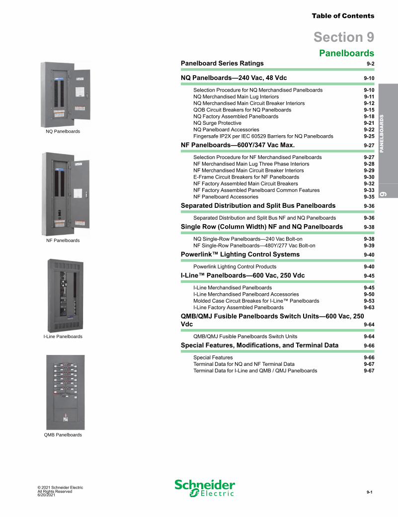
NQ Panelboards
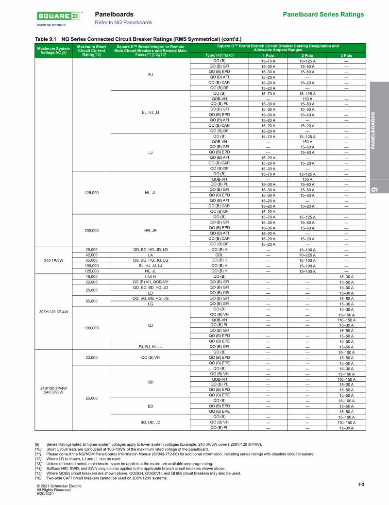
I-Line Panelboards
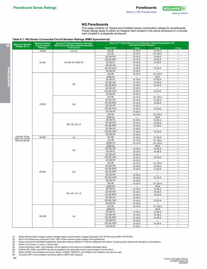
NF Panelboards
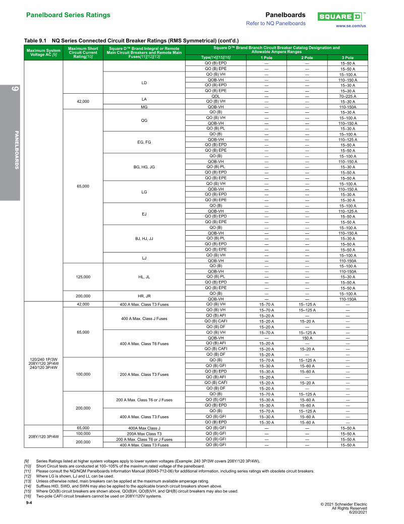
QMB Panelboards
Table of Contents
Section 9Panelboards
Panelboard Series Ratings 9-2
NQ Panelboards—240 Vac, 48 Vdc 9-10
Selection Procedure for NQ Merchandised Panelboards 9-10NQ Merchandised Main Lug Interiors 9-11NQ Merchandised Main Circuit Breaker Interiors 9-12QOB Circuit Breakers for NQ Panelboards 9-15NQ Factory Assembled Panelboards 9-18NQ Surge Protective 9-21NQ Panelboard Accessories 9-22Fingersafe IP2X per IEC 60529 Barriers for NQ Panelboards 9-25
NF Panelboards—600Y/347 Vac Max. 9-27
Selection Procedure for NF Merchandised Panelboards 9-27NF Merchandised Main Lug Three Phase Interiors 9-28NF Merchandised Main Circuit Breaker Interiors 9-29E-Frame Circuit Breakers for NF Panelboards 9-30NF Factory Assembled Main Circuit Breakers 9-32NF Factory Assembled Panelboard Common Features 9-33NF Panelboard Accessories 9-35
Separated Distribution and Split Bus Panelboards 9-36
Separated Distribution and Split Bus NF and NQ Panelboards 9-36
Single Row (Column Width) NF and NQ Panelboards 9-38
NQ Single-Row Panelboards—240 Vac Bolt-on 9-38NF Single-Row Panelboards—480Y/277 Vac Bolt-on 9-39
Powerlink™ Lighting Control Systems 9-40
Powerlink Lighting Control Products 9-40
I-Line™ Panelboards—600 Vac, 250 Vdc 9-45
I-Line Merchandised Panelboards 9-45I-Line Merchandised Panelboard Accessories 9-50Molded Case Circuit Breakes for I-Line™ Panelboards 9-53I-Line Factory Assembled Panelboards 9-63
QMB/QMJ Fusible Panelboards Switch Units—600 Vac, 250Vdc 9-64
QMB/QMJ Fusible Panelboards Switch Units 9-64
Special Features, Modifications, and Terminal Data 9-66
Special Features 9-66Terminal Data for NQ and NF Terminal Data 9-67Terminal Data for I-Line and QMB / QMJ Panelboards 9-67
9PA
NELBOARDS
9-2 © 2021 Schneider Electric All Rights Reserved
6/20/2021
Panelboard Series Ratings Panelboardswww.se.com/usRefer to NQ Panelboards
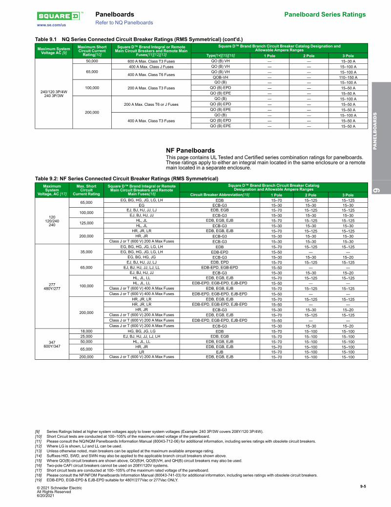
NQ PanelboardsThis page contains UL Tested and Certified series combination ratings for panelboards.These ratings apply to either an integral main located in the same enclosure or a remotemain located in a separate enclosure.
Table 9.1: NQ Series Connected Circuit Breaker Ratings (RMS Symmetrical)
Maximum SystemVoltage AC [1]
Maximum ShortCircuit Current
Rating[2]
Square D™ Brand Integral or RemoteMain Circuit Breakers and Remote Main
Fuses[3][4][5]
Square D™ Brand Branch Circuit Breaker Catalog Designation andAllowable Ampere Ranges
Type[6][7][8] 1 Pole 2 Pole 3 Pole
120/240 1P/3W208Y/120 3P/4W240/120 3P/4W
18,000 LA / LH QO (B) 15–30 A 15–30 A —
22,000 QO (B) VH, QOB-VH
QO (B) 15–70 A 15–125 A —QO (B) GFI 15–30 A 15–60 A —QO (B) EPD 15–30 A 15–60 A —QO (B) PL 15–30 A 15–60 A —QO (B) AFI 15–20 A — —QO (B) CAFI 15–20 A 15–20 A —QO (B) DF 15–20 A — —
25,000
QD
QO (B) 15–70 A 15–125 A —QOB-VH — 150 A —QO (B) PL 15–30 A 15–60 A —QO (B) GFI 15–30 A 15–60 A —QO (B) EPD 15–30 A 15–60 A —QO (B) AFI 15–20 A — —QO (B) CAFI 15–20 A 15–20 A —QO (B) DF 15–20 A — —
ED
QO (B) 15–70 A 15–125 A —QO (B) GFI 15–30 A 15–60 A —QO (B) EPD 15–30 A 15–60 A —QO (B) AFI 15–20 A — —QO (B) CAFI 15–20 A 15–20 A —QO (B) DF 15–20 A — —
BD, HD, JD, LD
QO (B) 15–70 A 15–125 A —QOB-VH — 150 A —QO (B) PL 15–30 A 15–60 A —QO (B) GFI 15–30 A 15–60 A —QO (B) EPD 15–30 A 15–60 A —QO (B) AFI 15–20 A — —QO (B) CAFI 15–20 A 15–20 A —QO (B) DF 15–20 A — —
42,000 LA QO (B) 15–30 A 15–30 A —
65,000
QG
QO (B) 15–70 A 15–125 A —QO(B) VH 15–70 A 15–125 A —QOB-VH — 150 A —QO (B) GFI 15–30 A 15–60 A —QO (B) PL 15–30 A 15–60 A —QO (B) AFI 15–20 A — —QO (B) CAFI 15–20 A 15–20 A —QO (B) DF 15–20 A — —
EG
QO (B) 15–70 A 15–125 A —QO (B) GFI 15–30 A 15–60 A —QO (B) EPD 15–30 A 15–60 A —QO (B) EPE — — —QO (B) AFI 15–20 A — —QO (B) CAFI 15–20 A 15–20 A —QO (B) DF 15–20 A — —
BG, HG, JG, LG
QO (B) 15–70 A 15–125 A —QOB-VH — 150 A —QO (B) PL 15–30 A 15–60 A —QO (B) GFI 15–30 A 15–60 A —QO (B) EPD 15–30 A 15–60 A —QO (B) AFI 15–20 A — —QO (B) CAFI 15–20 A 15–20 A —QO (B) DF 15–20 A — —
100,000 QJ
QO (B) 15–70 A 15–125 A —QOB-VH — 150 A —QO (B) PL 15–30 A 15–60 A —QO (B) GFI 15–30 A 15–60 A —QO (B) EPD 15–30 A 15–60 A —QO (B) AFI 15–20 A — —QO (B) CAFI 15–20 A 15–20 A —QO (B) DF 15–20 A — —
9PA
NELBOARDS
[1] Series Ratings listed at higher system voltages apply to lower system voltages (Example: 240 3P/3W covers 208Y/120 3P/4W).[2] Short Circuit tests are conducted at 100–105% of the maximum rated voltage of the panelboard.[3] Please consult the NQ/NQM Panelboards Information Manual (80043-712-06) for additional information, including series ratings with obsolete circuit breakers.[4] Where LG is shown, LJ and LL can be used.[5] Unless otherwise noted, main breakers can be applied at the maximum available amperage rating.[6] Suffixes HID, SWD, and SWN may also be applied to the applicable branch circuit breakers shown above.[7] Where QO(B) circuit breakers are shown above, QO(B)H, QO(B)VH, and QH(B) circuit breakers may also be used.[8] Two-pole CAFI circuit breakers cannot be used on 208Y/120V systems.
© 2021 Schneider Electric All Rights Reserved6/20/2021
9-3
www.se.com/us
Panelboards Panelboard Series RatingsRefer to NQ Panelboards
Table 9.1 NQ Series Connected Circuit Breaker Ratings (RMS Symmetrical) (cont'd.)
Maximum SystemVoltage AC [9]
Maximum ShortCircuit CurrentRating[10]
Square D™ Brand Integral or RemoteMain Circuit Breakers and Remote Main
Fuses[11][12][13]
Square D™ Brand Branch Circuit Breaker Catalog Designation andAllowable Ampere Ranges
Type[14][15][16] 1 Pole 2 Pole 3 Pole
EJ
QO (B) 15–70 A 15–125 A —QO (B) GFI 15–30 A 15–60 A —QO (B) EPD 15–30 A 15–60 A —QO (B) AFI 15–20 A — —QO (B) CAFI 15–20 A 15–20 A —QO (B) DF 15–20 A — —
BJ, HJ, JJ
QO (B) 15–70 A 15–125 A —QOB-VH — 150 A —QO (B) PL 15–30 A 15–60 A —QO (B) GFI 15–30 A 15–60 A —QO (B) EPD 15–30 A 15–60 A —QO (B) AFI 15–20 A — —QO (B) CAFI 15–20 A 15–20 A —QO (B) DF 15–20 A — —
LJ
QO (B) 15–70 A 15–125 A —QOB-VH — 150 A —QO (B) GFI — 15–60 A —QO (B) EPD — 15–60 A —QO (B) AFI 15–20 A — —QO (B) CAFI 15–20 A 15–20 A —QO (B) DF 15–20 A — —
125,000 HL, JL
QO (B) 15–70 A 15–125 A —QOB-VH — 150 A —QO (B) PL 15–30 A 15–60 A —QO (B) GFI 15–30 A 15–60 A —QO (B) EPD 15–30 A 15–60 A —QO (B) AFI 15–20 A — —QO (B) CAFI 15–20 A 15–20 A —QO (B) DF 15–20 A — —
200,000 HR, JR
QO (B) 15–70 A 15–125 A —QO (B) GFI 15–30 A 15–60 A —QO (B) EPD 15–30 A 15–60 A —QO (B) AFI 15–20 A — —QO (B) CAFI 15–20 A 15–20 A —QO (B) DF 15–20 A — —
240 1P/2W
25,000 QD, BD, HD, JD, LD QO (B) H — 15–100 A —42,000 LA QDL — 70–225 A —65,000 QG, BG, HG, JG, LG QO (B) H — 15–100 A —100,000 BJ, HJ, JJ, LJ QO (B) H — 15–100 A —125,000 HL, JL QO (B) H — 15–100 A —
208Y/120 3P/4W
18,000 LA/LH QO (B) — — 15–30 A22,000 QO (B) VH, QOB-VH QO (B) GFI — — 15–50 A
25,000QD, ED, BD, HD, JD QO (B) GFI — — 15–50 A
LD QO (B) GFI — — 15–30 A
65,000QG, EG, BG, HG, JG QO (B) GFI — — 15–50 A
LG QO (B) GFI — — 15–30 A
100,000 QJ
QO (B) — — 15–30 AQO (B) VH — — 15–100 AQOB-VH — — 110–150 AQO (B) PL — — 15–30 AQO (B) GFI — — 15–50 AQO (B) EPD — — 15–50 AQO (B) EPE — — 15–50 A
EJ, BJ, HJ, JJ QO (B) GFI — — 15–50 A
240/120 3P/4W240 3P/3W
22,000 QO (B) VHQO (B) — — 15–100 A
QO (B) EPD — — 15–50 AQO (B) EPE — — 15–50 A
25,000
QD
QO (B) — — 15–30 AQO (B) VH — — 15–100 AQOB-VH — — 110–150 AQO (B) PL — — 15–30 AQO (B) EPD — — 15–50 AQO (B) EPE — — 15–50 A
EDQO (B) — — 15–100 A
QO (B) EPD — — 15–50 AQO (B) EPE — — 15–50 A
BD, HD, JDQO (B) — — 15–100 A
QO (B) VH — — 110–150 AQO (B) PL — — 15–30 A
9PA
NELBOARDS
[9] Series Ratings listed at higher system voltages apply to lower system voltages (Example: 240 3P/3W covers 208Y/120 3P/4W).[10] Short Circuit tests are conducted at 100–105% of the maximum rated voltage of the panelboard.[11] Please consult the NQ/NQM Panelboards Information Manual (80043-712-06) for additional information, including series ratings with obsolete circuit breakers.[12] Where LG is shown, LJ and LL can be used.[13] Unless otherwise noted, main breakers can be applied at the maximum available amperage rating.[14] Suffixes HID, SWD, and SWN may also be applied to the applicable branch circuit breakers shown above.[15] Where QO(B) circuit breakers are shown above, QO(B)H, QO(B)VH, and QH(B) circuit breakers may also be used.[16] Two-pole CAFI circuit breakers cannot be used on 208Y/120V systems.
9-4 © 2021 Schneider Electric All Rights Reserved
6/20/2021
Panelboard Series Ratings Panelboardswww.se.com/usRefer to NQ Panelboards
Table 9.1 NQ Series Connected Circuit Breaker Ratings (RMS Symmetrical) (cont'd.)
Maximum SystemVoltage AC [9]
Maximum ShortCircuit CurrentRating[10]
Square D™ Brand Integral or RemoteMain Circuit Breakers and Remote Main
Fuses[11][12][13]
Square D™ Brand Branch Circuit Breaker Catalog Designation andAllowable Ampere Ranges
Type[14][15][16] 1 Pole 2 Pole 3 PoleQO (B) EPD — — 15–50 AQO (B) EPE — — 15–50 A
LD
QO (B) VH — — 15–100 AQOB-VH — — 110–150 A
QO (B) EPD — — 15–30 AQO (B) EPE — — 15–30 A
42,000 LAQDL — — 70–225 A
QO (B) VH — — 15–30 AMG QOB-VH — — 110-150A
65,000
QG
QO (B) — — 15–30 AQO (B) VH — — 15–100 AQOB-VH — — 110–150 AQO (B) PL — — 15–30 A
EG, FG
QO (B) — — 15–100 AQOB-VH — — 110–125 A
QO (B) EPD — — 15–50 AQO (B) EPE — — 15–50 A
BG, HG, JG
QO (B) — — 15–100 AQOB-VH — — 110–150 AQO (B) PL — — 15–30 AQO (B) EPD — — 15–50 AQO (B) EPE — — 15–50 A
LG
QO (B) VH — — 15–100 AQOB-VH — — 110–150 A
QO (B) EPD — — 15–30 AQO (B) EPE — — 15–30 A
EJ
QO (B) — — 15–100 AQOB-VH — — 110–125 A
QO (B) EPD — — 15–50 AQO (B) EPE — — 15–50 A
BJ, HJ, JJ
QO (B) — — 15–100 AQOB-VH — — 110–150 AQO (B) PL — — 15–30 AQO (B) EPD — — 15–50 AQO (B) EPE — — 15–50 A
LJQO (B) VH — — 15–100 AQOB-VH — — 110-150A
125,000 HL, JL
QO (B) — — 15–100 AQOB-VH — — 110-150AQO (B) PL — — 15–30 AQO (B) EPD — — 15–50 AQO (B) EPE — — 15–50 A
200,000 HR, JR QO (B) — — 15–100 AQOB-VH — — 110-150A
120/240 1P/3W208Y/120 3P/4W240/120 3P/4W
42,000 400 A Max. Class T3 Fuses QO (B) VH 15–70 A 15–125 A —
65,000
400 A Max. Class J Fuses
QO (B) VH 15–70 A 15–125 A —QO (B) AFI 15–20 A — —QO (B) CAFI 15–20 A 15–20 A —QO (B) DF 15–20 A — —
400 A Max. Class T6 Fuses
QO (B) VH 15–70 A 15–125 A —QOB-VH — 150 A —QO (B) AFI 15–20 A — —QO (B) CAFI 15–20 A 15–20 A —QO (B) DF 15–20 A — —
100,000 200 A Max. Class T3 Fuses
QO (B) 15–70 A 15–125 A —QO (B) GFI 15–30 A 15–60 A —QO (B) EPD 15–30 A 15–60 A —QO (B) AFI 15–20 A — —QO (B) CAFI 15–20 A 15–20 A —QO (B) DF 15–20 A — —
200,000
200 A Max. Class T6 or J FusesQO (B) 15–70 A 15–125 A —
QO (B) GFI 15–30 A 15–60 A —QO (B) EPD 15–30 A 15–60 A —
400 A Max. Class T3 FusesQO (B) 15–70 A 15–125 A —
QO (B) GFI 15–30 A 15–60 A —QO (B) EPD 15–30 A 15–60 A —
208Y/120 3P/4W
65,000 400A Max Class J QO (B) GFI — — 15–50 A100,000 200A Max Class T3 QO (B) GFI — — 15–50 A
200,000 200 A Max. Class T6 or J Fuses QO (B) GFI — — 15–50 A400 A Max. Class T3 Fuses QO (B) GFI — — 15–50 A
9PA
NELBOARDS
[9] Series Ratings listed at higher system voltages apply to lower system voltages (Example: 240 3P/3W covers 208Y/120 3P/4W).[10] Short Circuit tests are conducted at 100–105% of the maximum rated voltage of the panelboard.[11] Please consult the NQ/NQM Panelboards Information Manual (80043-712-06) for additional information, including series ratings with obsolete circuit breakers.[12] Where LG is shown, LJ and LL can be used.[13] Unless otherwise noted, main breakers can be applied at the maximum available amperage rating.[14] Suffixes HID, SWD, and SWN may also be applied to the applicable branch circuit breakers shown above.[15] Where QO(B) circuit breakers are shown above, QO(B)H, QO(B)VH, and QH(B) circuit breakers may also be used.[16] Two-pole CAFI circuit breakers cannot be used on 208Y/120V systems.
© 2021 Schneider Electric All Rights Reserved6/20/2021
9-5
www.se.com/us
Panelboards Panelboard Series RatingsRefer to NQ Panelboards
Table 9.1 NQ Series Connected Circuit Breaker Ratings (RMS Symmetrical) (cont'd.)
Maximum SystemVoltage AC [9]
Maximum ShortCircuit CurrentRating[10]
Square D™ Brand Integral or RemoteMain Circuit Breakers and Remote Main
Fuses[11][12][13]
Square D™ Brand Branch Circuit Breaker Catalog Designation andAllowable Ampere Ranges
Type[14][15][16] 1 Pole 2 Pole 3 Pole
240/120 3P/4W240 3P/3W
50,000 600 A Max. Class T3 Fuses QO (B) VH — — 15–30 A
65,000400 A Max. Class J Fuses QO (B) VH — — 15–100 A
400 A Max. Class T6 FusesQO (B) VH — — 15–100 AQOB-VH — — 110–150 A
100,000 200 A Max. Class T3 FusesQO (B) — — 15–100 A
QO (B) EPD — — 15–50 AQO (B) EPE — — 15–50 A
200,000
200 A Max. Class T6 or J FusesQO (B) — — 15–100 A
QO (B) EPD — — 15–50 AQO (B) EPE — — 15–50 A
400 A Max. Class T3 FusesQO (B) — — 15–100 A
QO (B) EPD — — 15–50 AQO (B) EPE — — 15–50 A
NF PanelboardsThis page contains ULTested and Certified series combination ratings for panelboards.These ratings apply to either an integral main located in the same enclosure or a remotemain located in a separate enclosure.
Table 9.2: NF Series Connected Circuit Breaker Ratings (RMS Symmetrical)MaximumSystem
Voltage, AC [17]
Max. ShortCircuit
Current Rating
Square D™ Brand Integral or RemoteMain Circuit Breakers and Remote
Main Fuses[18]
Square D™ Brand Branch Circuit Breaker CatalogDesignation and Allowable Ampere Ranges
Circuit Breaker Abbreviation[19] 1 Pole 2 Pole 3 Pole
120120/240240
65,000 EG, BG, HG, JG, LG, LH EDB 15–70 15–125 15–125EG ECB-G3 15–30 15–30 15–30
100,000EJ, BJ, HJ, JJ, LJ EDB, EGB 15–70 15–125 15–125EJ, BJ, HJ, JJ ECB-G3 15–30 15–30 15–30
125,000HL, JL EDB, EGB, EJB 15–70 15–125 15–125HL, JL ECB-G3 15–30 15–30 15–30
200,000HR, JR, LR EDB, EGB, EJB 15–70 15–125 15–125HR, JR ECB-G3 15–30 15–30 15–30
Class J or T (600 V) 200 A Max Fuses ECB-G3 15–30 15–30 15–30
277480Y/277
35,000EG, BG, HG, JG, LG, LH EDB 15–70 15–125 15–125EG, BG, HG, JG, LG, LH EDB-EPD 15–50 — —
EG, BG, HG, JG ECB-G3 15–30 15–30 15–20
65,000EJ, BJ, HJ, JJ, LJ EDB, EPD 15–70 15–125 15–125
EJ, BJ, HJ, JJ, LJ, LL EDB-EPD, EGB-EPD 15–50 — —EJ, BJ, HJ, JJ ECB-G3 15–30 15–30 15–20
100,000
HL, JL, LL EDB, EGB, EJB 15–70 15–125 15–125HL, JL, LL EDB-EPD, EGB-EPD, EJB-EPD 15–50 — —
Class J or T (600 V) 400 A Max Fuses EDB, EGB, EJB 15–70 15–125 15–125Class J or T (600 V) 400 A Max Fuses EDB-EPD, EGB-EPD, EJB-EPD 15–50 — —
200,000
HR, JR, LR EDB, EGB, EJB 15–70 15–125 15–125HR, JR, LR EDB-EPD, EGB-EPD, EJB-EPD 15–50 — —HR, JR ECB-G3 15–30 15–30 15–20
Class J or T (600 V) 200 A Max Fuses EDB, EGB, EJB 15–70 15–125 15–125Class J or T (600 V) 200 A Max Fuses EDB-EPD, EGB-EPD, EJB-EPD 15–50 — —Class J or T (600 V) 200 A Max Fuses ECB-G3 15–30 15–30 15–20
347600Y/347
18,000 HG, BG, JG, LG EDB 15–70 15–100 15–10025,000 EJ, BJ, HJ, JJ, LJ, LH EDB, EGB 15–70 15–100 15–10050,000 HL, JL, LL EDB, EGB, EJB 15–70 15–100 15–100
65,000 HR, JR EDB, EGB, EJB 15–70 15–100 15–100LR EJB 15–70 15–100 15–100
200,000 Class J or T (600 V) 200 A Max Fuses EDB, EGB, EJB 15–70 15–100 15–100
9PA
NELBOARDS
[9] Series Ratings listed at higher system voltages apply to lower system voltages (Example: 240 3P/3W covers 208Y/120 3P/4W).[10] Short Circuit tests are conducted at 100–105% of the maximum rated voltage of the panelboard.[11] Please consult the NQ/NQM Panelboards Information Manual (80043-712-06) for additional information, including series ratings with obsolete circuit breakers.[12] Where LG is shown, LJ and LL can be used.[13] Unless otherwise noted, main breakers can be applied at the maximum available amperage rating.[14] Suffixes HID, SWD, and SWN may also be applied to the applicable branch circuit breakers shown above.[15] Where QO(B) circuit breakers are shown above, QO(B)H, QO(B)VH, and QH(B) circuit breakers may also be used.[16] Two-pole CAFI circuit breakers cannot be used on 208Y/120V systems.[17] Short circuit tests are conducted at 100–105% of the maximum rated voltage of the panelboard.[18] Please consult the NF/NFOM Panelboards Information Manual (80043-741-03) for additional information, including series ratings with obsolete circuit breakers.[19] EDB-EPD, EGB-EPD & EJB-EPD suitable for 480Y/277Vac or 277Vac ONLY.
9-6 © 2021 Schneider Electric All Rights Reserved
6/20/2021
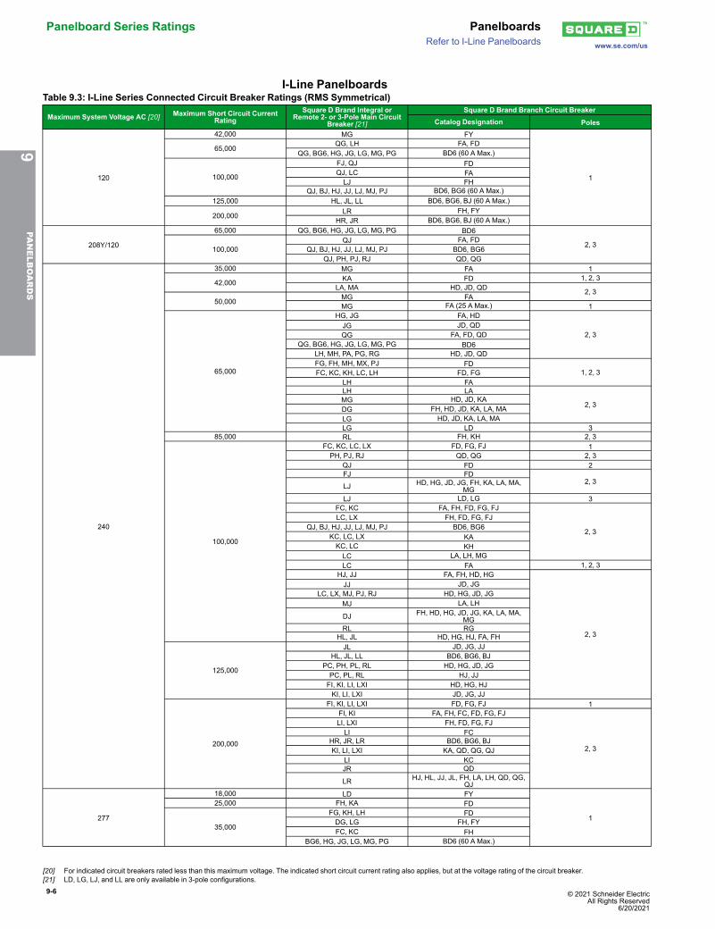
Panelboard Series Ratings Panelboardswww.se.com/usRefer to I-Line Panelboards
I-Line PanelboardsTable 9.3: I-Line Series Connected Circuit Breaker Ratings (RMS Symmetrical)
Maximum System Voltage AC [20] Maximum Short Circuit CurrentRating
Square D Brand Integral orRemote 2- or 3-Pole Main Circuit
Breaker [21]
Square D Brand Branch Circuit BreakerCatalog Designation Poles
120
42,000 MG FY
1
65,000QG, LH FA, FD
QG, BG6, HG, JG, LG, MG, PG BD6 (60 A Max.)
100,000
FJ, QJ FDQJ, LC FALJ FH
QJ, BJ, HJ, JJ, LJ, MJ, PJ BD6, BG6 (60 A Max.)125,000 HL, JL, LL BD6, BG6, BJ (60 A Max.)
200,000 LR FH, FYHR, JR BD6, BG6, BJ (60 A Max.)
208Y/120
65,000 QG, BG6, HG, JG, LG, MG, PG BD6
2, 3100,000
QJ FA, FDQJ, BJ, HJ, JJ, LJ, MJ, PJ BD6, BG6
QJ, PH, PJ, RJ QD, QG
240
35,000 MG FA 1
42,000 KA FD 1, 2, 3LA, MA HD, JD, QD 2, 3
50,000 MG FAMG FA (25 A Max.) 1
65,000
HG, JG FA, HD
2, 3JG JD, QDQG FA, FD, QD
QG, BG6, HG, JG, LG, MG, PG BD6LH, MH, PA, PG, RG HD, JD, QDFG, FH, MH, MX, PJ FD
1, 2, 3FC, KC, KH, LC, LH FD, FGLH FALH LA
2, 3MG HD, JD, KADG FH, HD, JD, KA, LA, MALG HD, JD, KA, LA, MALG LD 3
85,000 RL FH, KH 2, 3
100,000
FC, KC, LC, LX FD, FG, FJ 1PH, PJ, RJ QD, QG 2, 3
QJ FD 2FJ FD
2, 3LJ HD, HG, JD, JG, FH, KA, LA, MA,
MGLJ LD, LG 3
FC, KC FA, FH, FD, FG, FJ
2, 3
LC, LX FH, FD, FG, FJQJ, BJ, HJ, JJ, LJ, MJ, PJ BD6, BG6
KC, LC, LX KAKC, LC KHLC LA, LH, MGLC FA 1, 2, 3
HJ, JJ FA, FH, HD, HG
2, 3
JJ JD, JGLC, LX, MJ, PJ, RJ HD, HG, JD, JG
MJ LA, LH
DJ FH, HD, HG, JD, JG, KA, LA, MA,MG
RL RGHL, JL HD, HG, HJ, FA, FH
125,000
JL JD, JG, JJHL, JL, LL BD6, BG6, BJ
PC, PH, PL, RL HD, HG, JD, JGPC, PL, RL HJ, JJFI, KI, LI, LXI HD, HG, HJKI, LI, LXI JD, JG, JJ
200,000
FI, KI, LI, LXI FD, FG, FJ 1FI, KI FA, FH, FC, FD, FG, FJ
2, 3
LI, LXI FH, FD, FG, FJLI FC
HR, JR, LR BD6, BG6, BJKI, LI, LXI KA, QD, QG, QJ
LI KCJR QD
LR HJ, HL, JJ, JL, FH, LA, LH, QD, QG,QJ
277
18,000 LD FY
1
25,000 FH, KA FD
35,000
FG, KH, LH FDDG, LG FH, FYFC, KC FH
BG6, HG, JG, LG, MG, PG BD6 (60 A Max.)
9PA
NELBOARDS
[20] For indicated circuit breakers rated less than this maximum voltage. The indicated short circuit current rating also applies, but at the voltage rating of the circuit breaker.[21] LD, LG, LJ, and LL are only available in 3-pole configurations.
© 2021 Schneider Electric All Rights Reserved6/20/2021
9-7
www.se.com/us
Panelboards Panelboard Series RatingsRefer to I-Line Panelboards
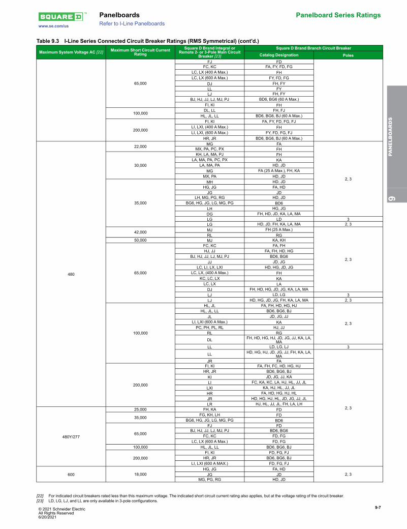
Table 9.3 I-Line Series Connected Circuit Breaker Ratings (RMS Symmetrical) (cont'd.)
Maximum System Voltage AC [22] Maximum Short Circuit CurrentRating
Square D Brand Integral orRemote 2- or 3-Pole Main Circuit
Breaker [23]
Square D Brand Branch Circuit BreakerCatalog Designation Poles
65,000
FJ FDFC, KC FA, FY, FD, FG
LC, LX (400 A Max.) FHLC, LX (600 A Max.) FY, FD, FG
DJ FH, FYLL FYLJ FH, FY
BJ, HJ, JJ, LJ, MJ, PJ BD6, BG6 (60 A Max.)FI, KI FH
100,000DL, LL FH, FJ
HL, JL, LL BD6, BG6, BJ (60 A Max.)
200,000
FI, KI FA, FY, FD, FG, FJLI, LXI, (400 A Max.) FHLI, LXI, (600 A Max.) FY, FD, FG, FJ
HR, JR BD6, BG6, BJ (60 A Max.)
480
22,000 MG FA
2, 3
MX, PA, PC, PX FH
30,000
KH, LA, MA, PJ FHLA, MA, PA, PC, PX KA
LA, MA, PA HD, JDMG FA (25 A Max.), FH, KA
MX, PA HD, JD
35,000
MH HD, JDHG, JG FA, HDJG JD
LH, MG, PG, RG HD, JDBG6, HG, JG, LG, MG, PG BD6
LH HG, JGDG FH, HD, JD, KA, LA, MALG LD 3LG HD, JD, FH, KA, LA, MA 2, 3
42,000 MJ FH (25 A Max.)
2, 3
RL RG50,000 MJ KA, KH
65,000
FC, KC FA, FHHJ, JJ FA, FH, HD, HG
BJ, HJ, JJ, LJ, MJ, PJ BD6, BG6JJ JD, JG
LC, LI, LX, LXI HD, HG, JD, JGLC, LX, (400 A Max.) FH
KC, LC, LX KALC, LX LADJ FH, HD, HG, JD, JG, KA, LA, MALJ LD, LG 3LJ HD, HG, JD, JG, FH, KA, LA, MA 2, 3
100,000
HL, JL FA, FH, HD, HG, HJ
2, 3
HL, JL, LL BD6, BG6, BJJL JD, JG, JJ
LI, LXI (600 A Max.) KAPC, PH, PL, RL HJ, JJ
RL RG
DL FH, HD, HG, HJ, JD, JG, JJ, KA, LA,MA
LL LD, LG, LJ 3
LL HD, HG, HJ, JD, JG, JJ, FH, KA, LA,MA
2, 3
JR FA
200,000
FI, KI FA, FH, FC, HD, HG, HJHR, JR BD6, BG6, BJKI JD, JG, JJ, KALI FC, KA, KC, LA, HJ, HL, JJ, JLLXI KA, HJ, HL, JJ, JLHR FA, HD, HG, HJ, HLJR HD, HG, HJ, HL, JD, JG, JJ, JLLR HJ, HL, JJ, JL, FH, LA, LH
480Y/277
25,000 FH, KA FD
35,000FG, KH, LH FD
BG6, HG, JG, LG, MG, PG BD6
65,000
FJ FDBJ, HJ, JJ, LJ, MJ, PJ BD6, BG6
FC, KC FD, FGLC, LX (600 A Max.) FD, FG
100,000 HL, JL, LL BD6, BG6, BJ
200,000FI, KI FD, FG, FJHR, JR BD6, BG6, BJ
LI, LXI (600 A MAX.) FD, FG, FJ
600 18,000HG, JG FA, HD
2, 3JG JDMG, PG, RG HD, JD
9PA
NELBOARDS
[22] For indicated circuit breakers rated less than this maximum voltage. The indicated short circuit current rating also applies, but at the voltage rating of the circuit breaker.[23] LD, LG, LJ, and LL are only available in 3-pole configurations.
9-8 © 2021 Schneider Electric All Rights Reserved
6/20/2021
Panelboard Series Ratings Panelboardswww.se.com/usRefer to I-Line Panelboards
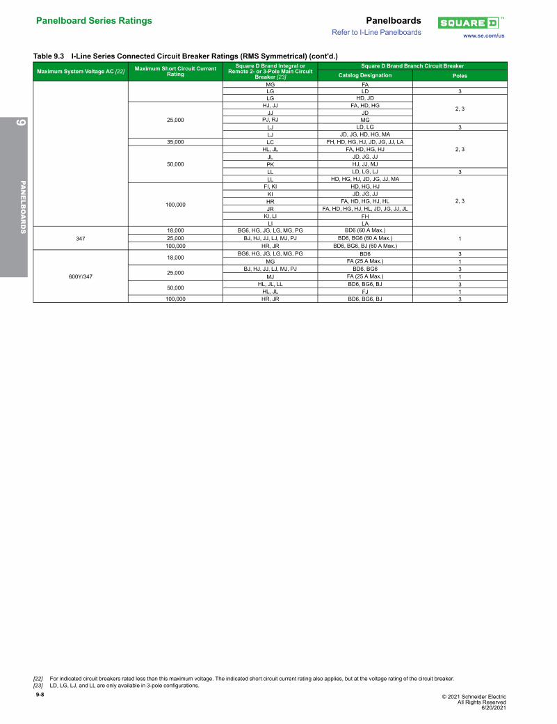
Table 9.3 I-Line Series Connected Circuit Breaker Ratings (RMS Symmetrical) (cont'd.)
Maximum System Voltage AC [22] Maximum Short Circuit CurrentRating
Square D Brand Integral orRemote 2- or 3-Pole Main Circuit
Breaker [23]
Square D Brand Branch Circuit BreakerCatalog Designation Poles
MG FALG LD 3LG HD, JD
2, 3
25,000
HJ, JJ FA, HD, HGJJ JD
PJ, RJ MGLJ LD, LG 3LJ JD, JG, HD, HG, MA
2, 335,000 LC FH, HD, HG, HJ, JD, JG, JJ, LA
50,000
HL, JL FA, HD, HG, HJJL JD, JG, JJPK HJ, JJ, MJLL LD, LG, LJ 3LL HD, HG, HJ, JD, JG, JJ, MA
2, 3100,000
FI, KI HD, HG, HJKI JD, JG, JJHR FA, HD, HG, HJ, HLJR FA, HD, HG, HJ, HL, JD, JG, JJ, JLKI, LI FHLI LA
34718,000 BG6, HG, JG, LG, MG, PG BD6 (60 A Max.)
125,000 BJ, HJ, JJ, LJ, MJ, PJ BD6, BG6 (60 A Max.)100,000 HR, JR BD6, BG6, BJ (60 A Max.)
600Y/347
18,000BG6, HG, JG, LG, MG, PG BD6 3
MG FA (25 A Max.) 1
25,000BJ, HJ, JJ, LJ, MJ, PJ BD6, BG6 3
MJ FA (25 A Max.) 1
50,000HL, JL, LL BD6, BG6, BJ 3HL, JL FJ 1
100,000 HR, JR BD6, BG6, BJ 3
9PA
NELBOARDS
[22] For indicated circuit breakers rated less than this maximum voltage. The indicated short circuit current rating also applies, but at the voltage rating of the circuit breaker.[23] LD, LG, LJ, and LL are only available in 3-pole configurations.
9-9
www.se.com/us
Panelboards Panelboard Series RatingsRefer to I-Line Panelboards
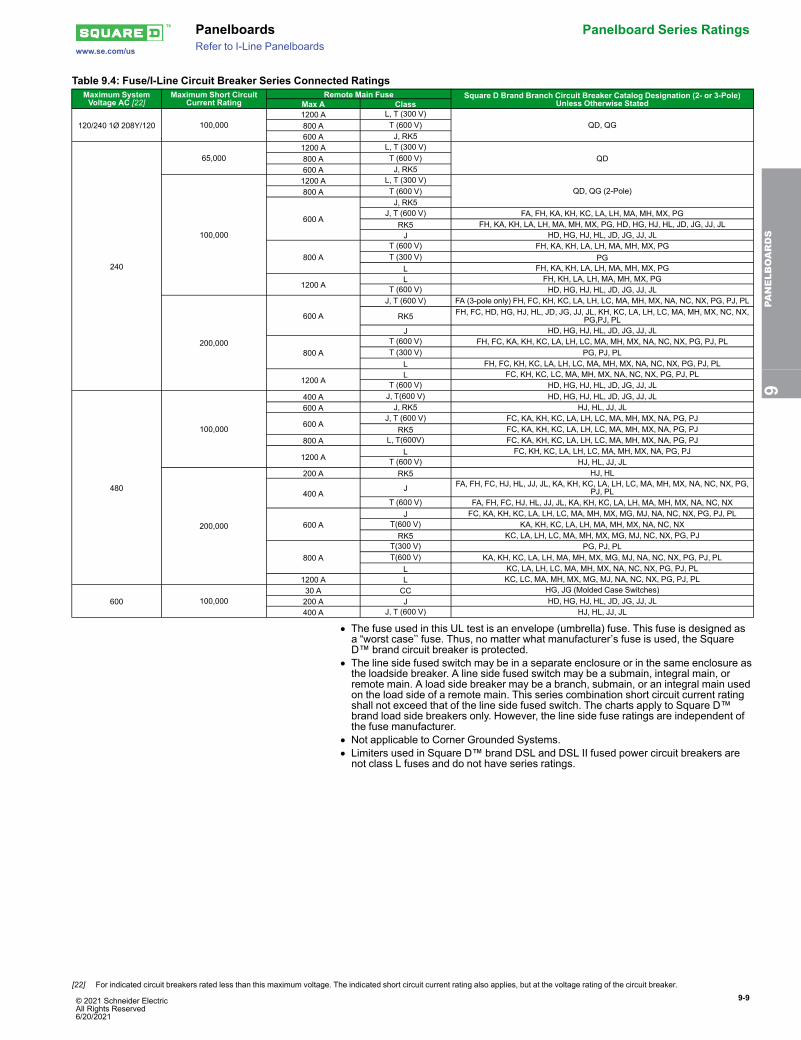
Table 9.4: Fuse/I-Line Circuit Breaker Series Connected RatingsMaximum SystemVoltage AC [22]
Maximum Short CircuitCurrent Rating
Remote Main Fuse Square D Brand Branch Circuit Breaker Catalog Designation (2- or 3-Pole)Unless Otherwise StatedMax A Class
120/240 1Ø 208Y/120 100,0001200 A L, T (300 V)
QD, QG800 A T (600 V)600 A J, RK5
240
65,0001200 A L, T (300 V)
QD800 A T (600 V)600 A J, RK5
100,000
1200 A L, T (300 V)QD, QG (2-Pole)800 A T (600 V)
600 A
J, RK5J, T (600 V) FA, FH, KA, KH, KC, LA, LH, MA, MH, MX, PG
RK5 FH, KA, KH, LA, LH, MA, MH, MX, PG, HD, HG, HJ, HL, JD, JG, JJ, JLJ HD, HG, HJ, HL, JD, JG, JJ, JL
800 AT (600 V) FH, KA, KH, LA, LH, MA, MH, MX, PGT (300 V) PG
L FH, KA, KH, LA, LH, MA, MH, MX, PG
1200 AL FH, KH, LA, LH, MA, MH, MX, PG
T (600 V) HD, HG, HJ, HL, JD, JG, JJ, JL
200,000
600 A
J, T (600 V) FA (3-pole only) FH, FC, KH, KC, LA, LH, LC, MA, MH, MX, NA, NC, NX, PG, PJ, PL
RK5 FH, FC, HD, HG, HJ, HL, JD, JG, JJ, JL, KH, KC, LA, LH, LC, MA, MH, MX, NC, NX,PG,PJ, PL
J HD, HG, HJ, HL, JD, JG, JJ, JL
800 AT (600 V) FH, FC, KA, KH, KC, LA, LH, LC, MA, MH, MX, NA, NC, NX, PG, PJ, PLT (300 V) PG, PJ, PL
L FH, FC, KH, KC, LA, LH, LC, MA, MH, MX, NA, NC, NX, PG, PJ, PL
1200 AL FC, KH, KC, LC, MA, MH, MX, NA, NC, NX, PG, PJ, PL
T (600 V) HD, HG, HJ, HL, JD, JG, JJ, JL
480
100,000
400 A J, T(600 V) HD, HG, HJ, HL, JD, JG, JJ, JL600 A J, RK5 HJ, HL, JJ, JL
600 AJ, T (600 V) FC, KA, KH, KC, LA, LH, LC, MA, MH, MX, NA, PG, PJ
RK5 FC, KA, KH, KC, LA, LH, LC, MA, MH, MX, NA, PG, PJ800 A L, T(600V) FC, KA, KH, KC, LA, LH, LC, MA, MH, MX, NA, PG, PJ
1200 AL FC, KH, KC, LA, LH, LC, MA, MH, MX, NA, PG, PJ
T (600 V) HJ, HL, JJ, JL
200,000
200 A RK5 HJ, HL
400 AJ FA, FH, FC, HJ, HL, JJ, JL, KA, KH, KC, LA, LH, LC, MA, MH, MX, NA, NC, NX, PG,
PJ, PLT (600 V) FA, FH, FC, HJ, HL, JJ, JL, KA, KH, KC, LA, LH, MA, MH, MX, NA, NC, NX
600 AJ FC, KA, KH, KC, LA, LH, LC, MA, MH, MX, MG, MJ, NA, NC, NX, PG, PJ, PL
T(600 V) KA, KH, KC, LA, LH, MA, MH, MX, NA, NC, NXRK5 KC, LA, LH, LC, MA, MH, MX, MG, MJ, NC, NX, PG, PJ
800 AT(300 V) PG, PJ, PLT(600 V) KA, KH, KC, LA, LH, MA, MH, MX, MG, MJ, NA, NC, NX, PG, PJ, PL
L KC, LA, LH, LC, MA, MH, MX, NA, NC, NX, PG, PJ, PL1200 A L KC, LC, MA, MH, MX, MG, MJ, NA, NC, NX, PG, PJ, PL
600 100,00030 A CC HG, JG (Molded Case Switches)200 A J HD, HG, HJ, HL, JD, JG, JJ, JL400 A J, T (600 V) HJ, HL, JJ, JL
• The fuse used in this UL test is an envelope (umbrella) fuse. This fuse is designed asa “worst case’’ fuse. Thus, no matter what manufacturer’s fuse is used, the SquareD™ brand circuit breaker is protected.
• The line side fused switch may be in a separate enclosure or in the same enclosure asthe loadside breaker. A line side fused switch may be a submain, integral main, orremote main. A load side breaker may be a branch, submain, or an integral main usedon the load side of a remote main. This series combination short circuit current ratingshall not exceed that of the line side fused switch. The charts apply to Square D™brand load side breakers only. However, the line side fuse ratings are independent ofthe fuse manufacturer.
• Not applicable to Corner Grounded Systems.• Limiters used in Square D™ brand DSL and DSL II fused power circuit breakers arenot class L fuses and do not have series ratings.
9PA
NELBOARDS
[22] For indicated circuit breakers rated less than this maximum voltage. The indicated short circuit current rating also applies, but at the voltage rating of the circuit breaker.
© 2021 Schneider Electric All Rights Reserved6/20/2021
9-10 © 2021 Schneider Electric All Rights Reserved
6/20/2021
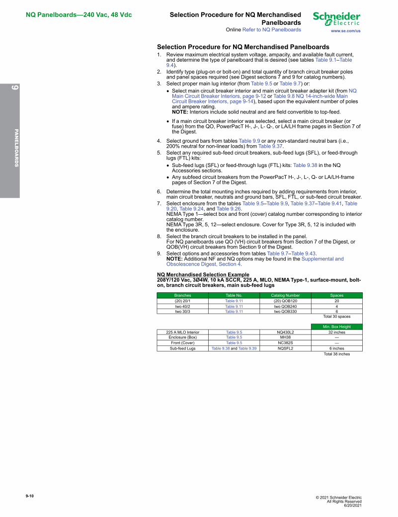
NQ Panelboards—240 Vac, 48 Vdc Selection Procedure for NQ MerchandisedPanelboards
www.se.com/usOnline Refer to NQ Panelboards
Selection Procedure for NQ Merchandised Panelboards1. Review maximum electrical system voltage, ampacity, and available fault current,
and determine the type of panelboard that is desired (see tables Table 9.1–Table9.4).
2. Identify type (plug-on or bolt-on) and total quantity of branch circuit breaker polesand panel spaces required (see Digest sections 7 and 9 for catalog numbers).
3. Select proper main lug interior (from Table 9.5 or Table 9.7) or:• Select main circuit breaker interior and main circuit breaker adapter kit (from NQMain Circuit Breaker Interiors, page 9-12 or Table 9.8 NQ 14-inch-wide MainCircuit Breaker Interiors, page 9-14), based upon the equivalent number of polesand ampere rating.NOTE: Interiors include solid neutral and are field convertible to top-feed.
• If a main circuit breaker interior was selected, select a main circuit breaker (orfuse) from the QO, PowerPacT H-, J-, L- Q-, or LA/LH frame pages in Section 7 ofthe Digest.
4. Select ground bars from tables Table 9.9 or any non-standard neutral bars (i.e.,200% neutral for non-linear loads) from Table 9.37.
5. Select any required sub-feed circuit breakers, sub-feed lugs (SFL), or feed-throughlugs (FTL) kits:• Sub-feed lugs (SFL) or feed-through lugs (FTL) kits: Table 9.38 in the NQAccessories sections.
• Any subfeed circuit breakers from the PowerPacT H-, J-, L-, Q- or LA/LH-framepages of Section 7 of the Digest.
6. Determine the total mounting inches required by adding requirements from interior,main circuit breaker, neutrals and ground bars, SFL, FTL, or sub-feed circuit breaker.
7. Select enclosure from the tables Table 9.5–Table 9.9, Table 9.37–Table 9.41, Table9.20, Table 9.24, and Table 9.26.NEMAType 1—select box and front (cover) catalog number corresponding to interiorcatalog number.NEMAType 3R, 5, 12—select enclosure. Cover for Type 3R, 5, 12 is included withthe enclosure.
8. Select the branch circuit breakers to be installed in the panel.For NQ panelboards use QO (VH) circuit breakers from Section 7 of the Digest, orQOB(VH) circuit breakers from Section 9 of the Digest.
9. Select options and accessories from tables Table 9.7–Table 9.43.NOTE: Additional NF and NQ options may be found in the Supplemental andObsolescence Digest, Section 4.
NQ Merchandised Selection Example208Y/120 Vac, 3Ø4W, 10 kA SCCR, 225 A, MLO, NEMAType-1, surface-mount, bolt-on, branch circuit breakers, main sub-feed lugs
Branches Table No. Catalog Number Spaces(20) 20/1 Table 9.11 (20) QOB120 20two 40/2 Table 9.11 two QOB240 4two 30/3 Table 9.11 two QOB330 6
Total 30 spaces
Min. Box Height225 A MLO Interior Table 9.5 NQ430L2 32 inchesEnclosure (Box) Table 9.5 MH38 —Front (Cover) Table 9.5 NC382S —Sub-feed Lugs Table 9.38 and Table 9.39 NQSFL2 6 inches
Total 38 inches
9PA
NELBOARDS
© 2021 Schneider Electric All Rights Reserved6/20/2021
9-11
www.se.com/us
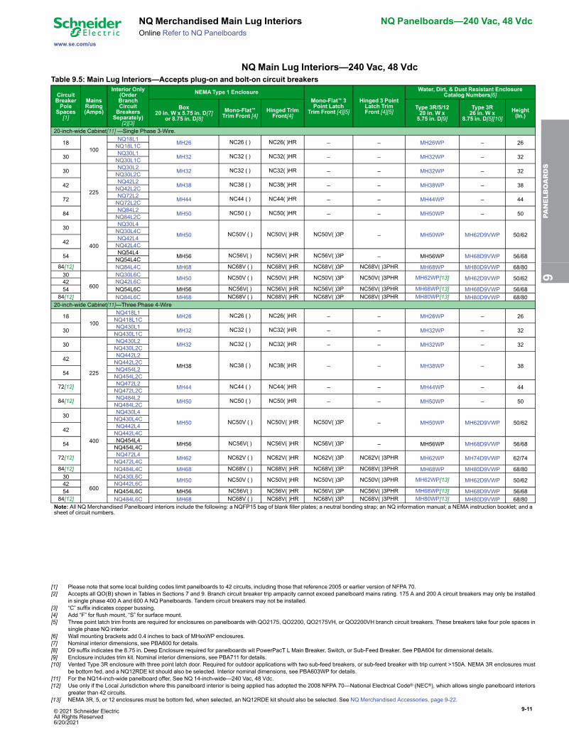
NQ Merchandised Main Lug Interiors NQ Panelboards—240 Vac, 48 VdcOnline Refer to NQ Panelboards
NQ Main Lug Interiors—240 Vac, 48 VdcTable 9.5: Main Lug Interiors—Accepts plug-on and bolt-on circuit breakers
CircuitBreakerPole
Spaces[1]
MainsRating(Amps)
Interior Only(OrderBranchCircuitBreakersSeparately)
[2][3]
NEMAType 1 EnclosureMono-Flat™ 3Point Latch
Trim Front [4][5]
Hinged 3 PointLatch TrimFront [4][5]
Water, Dirt, & Dust Resistant EnclosureCatalog Numbers[6]
Box20 in. W x 5.75 in. D[7]
or 8.75 in. D[8]Mono-Flat™Trim Front [4]
Hinged TrimFront[4]
Type 3R/5/1220 in. W x5.75 in. D[9]
Type 3R26 in. W x
8.75 in. D[5][10]Height(In.)
20-inch-wide Cabinet[11]—Single Phase 3-Wire.
18100
NQ18L1 MH26 NC26 ( ) NC26( )HR – – MH26WP – 26NQ18L1C
30 NQ30L1 MH32 NC32 ( ) NC32( )HR – – MH32WP – 32NQ30L1C
30
225
NQ30L2 MH32 NC32 ( ) NC32( )HR – – MH32WP – 32NQ30L2C
42 NQ42L2 MH38 NC38 ( ) NC38( )HR – – MH38WP – 38NQ42L2C
72 NQ72L2 MH44 NC44 ( ) NC44( )HR – – MH44WP – 44NQ72L2C
84 NQ84L2 MH50 NC50 ( ) NC50( )HR – – MH50WP – 50NQ84L2C
30
400
NQ30L4
MH50 NC50V ( ) NC50V( )HR NC50V( )3P – MH50WP MH62D9VWP 50/62NQ30L4C
42 NQ42L4NQ42L4C
54 NQ54L4 MH56 NC56V( ) NC56V( )HR NC56V( )3P – MH56WP MH68D9VWP 56/68NQ54L4C84[12] NQ84L4C MH68 NC68V ( ) NC68V( )HR NC68V( )3P NC68V( )3PHR MH68WP MH80D9VWP 68/8030
600
NQ30L6C MH50 NC50V ( ) NC50V( )HR NC50V( )3P NC50V( )3PHR MH62WP[13] MH62D9VWP 50/6242 NQ42L6C54 NQ54L6C MH56 NC56V( ) NC56V( )HR NC56V( )3P NC56V( )3PHR MH68WP[13] MH68D9VWP 56/68
84[12] NQ84L6C MH68 NC68V ( ) NC68V( )HR NC68V( )3P NC68V( )3PHR MH80WP[13] MH80D9VWP 68/8020-inch-wide Cabinet[11]—Three Phase 4-Wire
18100
NQ418L1 MH26 NC26 ( ) NC26( )HR – – MH26WP – 26NQ418L1C
30 NQ430L1 MH32 NC32 ( ) NC32( )HR – – MH32WP – 32NQ430L1C
30
225
NQ430L2 MH32 NC32 ( ) NC32( )HR – – MH32WP – 32NQ430L2C
42 NQ442L2
MH38 NC38 ( ) NC38( )HR – – MH38WP – 38NQ442L2C
54 NQ454L2NQ454L2C
72[12] NQ472L2 MH44 NC44 ( ) NC44( )HR – – MH44WP – 44NQ472L2C
84[12] NQ484L2 MH50 NC50 ( ) NC50( )HR – – MH50WP – 50NQ484L2C
30
400
NQ430L4
MH50 NC50V ( ) NC50V( )HR NC50V( )3P – MH50WP MH62D9VWP 50/62NQ430L4C
42 NQ442L4NQ442L4C
54 NQ454L4 MH56 NC56V( ) NC56V( )HR NC56V( )3P – MH56WP MH68D9VWP 56/68NQ454L4C
72[12] NQ472L4 MH62 NC62V ( ) NC62V( )HR NC62V( )3P NC62V( )3PHR MH62WP MH74D9VWP 62/74NQ472L4C84[12] NQ484L4C MH68 NC68V ( ) NC68V( )HR NC68V( )3P NC68V( )3PHR MH68WP MH80D9VWP 68/8030
600
NQ430L6C MH50 NC50V ( ) NC50V( )HR NC50V( )3P NC50V( )3PHR MH62WP[13] MH62D9VWP 50/6242 NQ442L6C54 NQ454L6C MH56 NC56V( ) NC56V( )HR NC56V( )3P NC56V( )3PHR MH68WP[13] MH68D9VWP 56/68
84[12] NQ484L6C MH68 NC68V ( ) NC68V( )HR NC68V( )3P NC68V( )3PHR MH80WP[13] MH80D9VWP 68/80Note: All NQ Merchandised Panelboard interiors include the following: a NQFP15 bag of blank filler plates; a neutral bonding strap; an NQ information manual; a NEMA instruction booklet; and asheet of circuit numbers.
9PA
NELBOARDS
[1] Please note that some local building codes limit panelboards to 42 circuits, including those that reference 2005 or earlier version of NFPA 70.[2] Accepts all QO(B) shown in Tables in Sections 7 and 9. Branch circuit breaker trip ampacity cannot exceed panelboard mains rating. 175 A and 200 A circuit breakers may only be installed
in single phase 400 A and 600 A NQ Panelboards. Tandem circuit breakers may not be installed.[3] “C” suffix indicates copper bussing.[4] Add “F” for flush mount, “S” for surface mount.[5] Three point latch trim fronts are required for enclosures on panelboards with QO2175, QO2200, QO2175VH, or QO2200VH branch circuit breakers. These breakers take four pole spaces in
single phase NQ interior.[6] Wall mounting brackets add 0.4 inches to back of MHxxWP enclosures.[7] Nominal interior dimensions, see PBA600 for details.[8] D9 suffix indicates the 8.75 in. Deep Enclosure required for panelboards wit PowerPacT L Main Breaker, Switch, or Sub-Feed Breaker. See PBA604 for dimensional details.[9] Enclosure includes trim kit. Nominal interior dimensions, see PBA711 for details.[10] Vented Type 3R enclosure with three point latch door. Required for outdoor applications with two sub-feed breakers, or sub-feed breaker with trip current >150A. NEMA 3R enclosures must
be bottom fed, and a NQ12RDE kit should also be selected. Interior nominal dimensions, see PBA603WP for details.[11] For the NQ14-inch-wide panelboard offer, See NQ 14-inch-wide—240 Vac, 48 Vdc.[12] Use only if the Local Jurisdiction where this panelboard interior is being applied has adopted the 2008 NFPA 70—National Electrical Code® (NEC®), which allows single panelboard interiors
greater than 42 circuits.[13] NEMA 3R, 5, or 12 enclosures must be bottom fed, when selected, an NQ12RDE kit should also be selected. See NQ Merchandised Accessories, page 9-22.
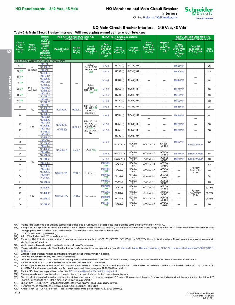
9-12 © 2021 Schneider Electric All Rights Reserved
6/20/2021
NQ Panelboards—240 Vac, 48 Vdc NQ Merchandised Main Circuit BreakerInteriors
www.se.com/usOnline Refer to NQ Panelboards
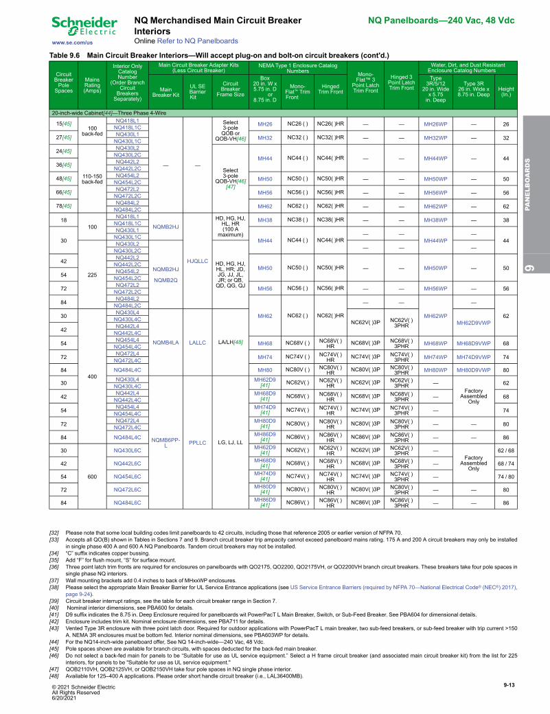
NQ Main Circuit Breaker Interiors—240 Vac, 48 VdcTable 9.6: Main Circuit Breaker Interiors—Will accept plug-on and bolt-on circuit breakers
CircuitBreakerPole
Spaces[14]
MainsRating(Amps)
InteriorOnly
CatalogNumber(OrderBranchCircuitBreakersSeparate-ly) [15][16]
Main Circuit Breaker Adapter Kits(Less Circuit Breaker)
NEMAType 1 Enclosure CatalogNumbers
Mono-Flat™ 3
Point LatchTrim Front[17][18]
Hinged 3Point
Latch TrimFront[17]
[18]
Water, Dirt, and Dust ResistantEnclosure Catalog Numbers [19]
Main BreakerKit
UL SEBarrierKit[20]
CircuitBreaker
Frame Size[21]
Box20 in. W x5.75 in. D[22] or
8.75 in. D[23]
Mono-Flat™ TrimFront [17]
HingedTrim Front
[17]
Type3R/5/12
20 in. Widex 5.75in. Deep[24]
Type 3R26 in. Wide x8.75 in. Deep
[25]
Heig-ht (In.)
20-inch-wide Cabinet [26]—Single Phase 3-Wire
16[27]100
back-fed
NQ18L1
— —
Select2-pole QOBor QOB-VH
[28]
MH26 NC26 ( ) NC26( )HR — — MH26WP — 26NQ18L1C
28[27] NQ30L1 MH32 NC32 ( ) NC32( )HR — — MH32WP — 32NQ30L1C
26[27]
110-150back-fed
NQ30L2
Select2-pole
QOB-VH[28][29]
MH44 NC44 ( ) NC44( )HR — — MH44WP—
44NQ30L2C
38[27] NQ42L2 —NQ42L2C
50[27] NQ54L2 MH50 NC50 ( ) NC50( )HR — — MH50WP — 50NQ54L2C
68[27] NQ72L2 MH56 NC56 ( ) NC56( )HR — — MH56WP — 56NQ72L2C
80[27] NQ84L2 MH62 NC62 ( ) NC62( )HR — — MH62WP — 62NQ84L2C
18100
NQ18L1
NQMB2HJ HJQLLCHD, HG, HJ,HL, HR[30](100 A
maximum)
MH38 NC38 ( ) NC38( )HR — — MH38WP — 38NQ18L1C
30
NQ30L1
MH44 NC44 ( ) NC44( )HR— —
MH44WP—
44NQ30L1C
225
NQ30L2
NQMB2HJ
NQMB2QHJQLLC
HD, HG, HJ,HL, HR, JD,JG, JJ, JL,JR[30]; or
QB, QD, QG,QJ
— — —NQ30L2C
42 NQ42L2 MH50 NC50 ( ) NC50( )HR — — MH50WP — 50NQ42L2C
72 NQ72L2 MH56 NC56 ( ) NC56( )HR — — MH56WP — 56NQ72L2C
84 NQ84L2
MH62
NC62 ( ) NC62( )HR — —
MH62WP
—
62
NQ84L2C
30
400
NQ30L4
NQMB4LA LALLC LA/LH[31]
NC62V ( ) NC62V( )HR NC62V( )3P NC62( )
3PHR MH62D9VWPNQ30L4C
42 NQ42L4NQ42L4C
54 NQ54L4 MH68 NC68V ( ) NC68V( )HR NC68V( )3P NC68V( )
3PHR MH68WP MH68D9VWP 68NQ54L4C
84 NQ84L4C MH80 NC80V ( ) NC80V( )HR NC80V( )3P NC80V( )
3PHR MH80WP MH80D9VWP 80
30 NQ30L4
NQMB6PPL PPLLC LG, LJ, LL
MH62D9[23] NC62V( ) NC62V( )
HR NC62V( )3P NC62V( )3PHR —
FactoryAssembled
Only
62NQ30L4C
42 NQ42L4 MH68D9[23] NC68V( ) NC68V( )
HR NC68V( )3P NC68V( )3PHR — 68NQ42L4C
54 NQ54L4 MH74D9[23] NC74V( ) NC74V( )
HR NC74V( )3P NC74V( )3PHR — 74NQ54LC
84 NQ84L4C MH86D9[23] NC86V( ) NC86V( )
HR NC86V( )3P NC86V( )3PHR — — 86
30
600
NQ30L6C
NQMB6PPL PPLLC LG, LJ, LL
MH62D9[23] NC62V( ) NC62V( )
HR NC62V( )3P NC62V( )3PHR —
FactoryAssembled
Only
62 / 68
42 NQ42L6C MH68D9[23] NC68V( ) NC68V( )
HR NC68V( )3P NC68V( )3PHR — 68 / 74
54 NQ54L6C MH74D9[23] NC74V( ) NC74V( )
HR NC74V( )3P NC74V( )3PHR — 74 / 80
84 NQ84L6C MH86D9[23] NC86V( ) NC86V( )
HR NC86V( )3P NC86V( )3PHR — — 86
9PA
NELBOARDS
[14] Please note that some local building codes limit panelboards to 42 circuits, including those that reference 2005 or earlier version of NFPA 70.[15] Accepts all QO(B) shown in Tables in Sections 7 and 9. Branch circuit breaker trip ampacity cannot exceed panelboard mains rating. 175 A and 200 A circuit breakers may only be installed
in single phase 400 A and 600 A NQ Panelboards. Tandem circuit breakers may not be installed.[16] “C” suffix indicates copper bussing.[17] Add “F” for flush mount, “S” for surface mount.[18] Three point latch trim fronts are required for enclosures on panelboards with QO2175, QO2200, QO2175VH, or QO2200VH branch circuit breakers. These breakers take four pole spaces in
single phase NQ interiors.[19] Wall mounting brackets add 0.4 inches to back of MHxxWP enclosures.[20] Please select the appropriate Main Breaker Barrier for UL Service Entrance applications (see US Service Entrance Barriers (required by NFPA 70—National Electrical Code® (NEC®) 2017),
page 9-24).[21] Circuit breaker interrupt ratings, see the table for each circuit breaker range in Section 7.[22] Nominal interior dimensions, see PBA600 for details.[23] D9 suffix indicates the 8.75 in. Deep Enclosure required for panelboards wit PowerPacT L Main Breaker, Switch, or Sub-Feed Breaker. See PBA604 for dimensional details.[24] Enclosure includes trim kit. Nominal enclosure dimensions, see PBA711 for details.[25] Vented Type 3R enclosure with three point latch door. Required for outdoor applications with PowerPacT L main breaker, two sub-feed breakers, or sub-feed breaker with trip current >150
A. NEMA 3R enclosures must be bottom fed. Interior nominal dimensions, see PBA603WP for details.[26] For the NQ14-inch-wide panelboard offer, See NQ 14-inch-wide—240 Vac, 48 Vdc, page 9-14.[27] Pole spaces shown are available for branch circuits, with spaces deducted for the back-fed main breaker.[28] Do not select a back-fed main for panels to be “Suitable for use as UL service equipment.” Select a H frame circuit breaker (and associated main circuit breaker kit) from the list for 225
interiors, for panels to be "Suitable for use as UL service equipment."[29] QOB2110VH, QOB2125VH, or QOB2150VH take four pole spaces in NQ single phase interior.[30] For single phase applications, order a 3-pole breaker. Example: HDL36100.[31] Available for 125–400 A applications. Please order short handle circuit breaker (i.e., LAL36400MB).
© 2021 Schneider Electric All Rights Reserved6/20/2021
9-13
www.se.com/us
NQ Merchandised Main Circuit BreakerInteriors
NQ Panelboards—240 Vac, 48 Vdc
Online Refer to NQ Panelboards
Table 9.6 Main Circuit Breaker Interiors—Will accept plug-on and bolt-on circuit breakers (cont'd.)
CircuitBreakerPole
Spaces[32]
MainsRating(Amps)
Interior OnlyCatalogNumber
(Order BranchCircuitBreakersSeparately)[33][34]
Main Circuit Breaker Adapter Kits(Less Circuit Breaker)
NEMAType 1 Enclosure CatalogNumbers Mono-
Flat™ 3Point LatchTrim Front[35][36]
Hinged 3Point LatchTrim Front[35][36]
Water, Dirt, and Dust ResistantEnclosure Catalog Numbers [37]
MainBreaker Kit
UL SEBarrierKit[38]
CircuitBreaker
Frame Size[39]
Box20 in. W x5.75 in. D[40] or
8.75 in. D[41]
Mono-Flat™ TrimFront [35]
HingedTrim Front
[35]
Type3R/5/12
20 in. Widex 5.75in. Deep[42]
Type 3R26 in. Wide x8.75 in. Deep
[43]
Height(In.)
20-inch-wide Cabinet[44]—Three Phase 4-Wire
15[45]100
back-fed
NQ418L1
— —
Select3-poleQOB or
QOB-VH[46]
MH26 NC26 ( ) NC26( )HR — — MH26WP — 26NQ418L1C
27[45] NQ430L1 MH32 NC32 ( ) NC32( )HR — — MH32WP — 32NQ430L1C
24[45]
110-150back-fed
NQ430L2
Select3-pole
QOB-VH[46][47]
MH44 NC44 ( ) NC44( )HR — — MH44WP — 44NQ430L2C
36[45] NQ442L2NQ442L2C
48[45] NQ454L2 MH50 NC50 ( ) NC50( )HR — — MH50WP — 50NQ454L2C
66[45] NQ472L2 MH56 NC56 ( ) NC56( )HR — — MH56WP — 56NQ472L2C
78[45] NQ484L2 MH62 NC62 ( ) NC62( )HR — — MH62WP — 62NQ484L2C
18100
NQ418L1
NQMB2HJ
HJQLLC
HD, HG, HJ,HL, HR(100 A
maximum)
MH38 NC38 ( ) NC38( )HR — — MH38WP — 38NQ418L1C
30
NQ430L1
MH44 NC44 ( ) NC44( )HR— —
MH44WP—
44NQ430L1C
225
NQ430L2
NQMB2HJ
NQMB2Q
HD, HG, HJ,HL, HR; JD,JG, JJ, JL,JR; or QB,QD, QG, QJ
— — —NQ430L2C
42 NQ442L2
MH50 NC50 ( ) NC50( )HR — — MH50WP — 50NQ442L2C
54 NQ454L2NQ454L2C
72 NQ472L2 MH56 NC56 ( ) NC56( )HR — — MH56WP — 56NQ472L2C
84 NQ484L2
MH62 NC62 ( ) NC62( )HR
— —
MH62WP
—
62
NQ484L2C
30
400
NQ430L4
NQMB4LA LALLC LA/LH[48]
NC62V( )3P NC62V( )3PHR MH62D9VWPNQ430L4C
42 NQ442L4NQ442L4C
54 NQ454L4 MH68 NC68V ( ) NC68V( )HR NC68V( )3P NC68V( )
3PHR MH68WP MH68D9VWP 68NQ454L4C
72 NQ472L4 MH74 NC74V ( ) NC74V( )HR NC74V( )3P NC74V( )
3PHR MH74WP MH74D9VWP 74NQ472L4C
84 NQ484L4C MH80 NC80V ( ) NC80V( )HR NC80V( )3P NC80V( )
3PHR MH80WP MH80D9VWP 80
30 NQ430L4
NQMB6PP-L PPLLC LG, LJ, LL
MH62D9[41] NC62V( ) NC62V( )
HR NC62V( )3P NC62V( )3PHR —
FactoryAssembled
Only
62NQ430L4C
42 NQ442L4 MH68D9[41] NC68V( ) NC68V( )
HR NC68V( )3P NC68V( )3PHR — 68NQ442L4C
54 NQ454L4 MH74D9[41] NC74V( ) NC74V( )
HR NC74V( )3P NC74V( )3PHR — 74NQ454L4C
72 NQ472L4 MH80D9[41] NC80V( ) NC80V( )
HR NC80V( )3P NC80V( )3PHR — — 80NQ472L4C
84 NQ484L4C MH86D9[41] NC86V( ) NC86V( )
HR NC86V( )3P NC86V( )3PHR — — 86
30
600
NQ430L6C MH62D9[41] NC62V( ) NC62V( )
HR NC62V( )3P NC62V( )3PHR —
FactoryAssembled
Only
62 / 68
42 NQ442L6C MH68D9[41] NC68V( ) NC68V( )
HR NC68V( )3P NC68V( )3PHR — 68 / 74
54 NQ454L6C MH74D9[41] NC74V( ) NC74V( )
HR NC74V( )3P NC74V( )3PHR — 74 / 80
72 NQ472L6C MH80D9[41] NC80V( ) NC80V( )
HR NC80V( )3P NC80V( )3PHR — — 80
84 NQ484L6C MH86D9[41] NC86V( ) NC86V( )
HR NC86V( )3P NC86V( )3PHR — — 86
9PA
NELBOARDS
[32] Please note that some local building codes limit panelboards to 42 circuits, including those that reference 2005 or earlier version of NFPA 70.[33] Accepts all QO(B) shown in Tables in Sections 7 and 9. Branch circuit breaker trip ampacity cannot exceed panelboard mains rating. 175 A and 200 A circuit breakers may only be installed
in single phase 400 A and 600 A NQ Panelboards. Tandem circuit breakers may not be installed.[34] “C” suffix indicates copper bussing.[35] Add “F” for flush mount, “S” for surface mount.[36] Three point latch trim fronts are required for enclosures on panelboards with QO2175, QO2200, QO2175VH, or QO2200VH branch circuit breakers. These breakers take four pole spaces in
single phase NQ interiors.[37] Wall mounting brackets add 0.4 inches to back of MHxxWP enclosures.[38] Please select the appropriate Main Breaker Barrier for UL Service Entrance applications (see US Service Entrance Barriers (required by NFPA 70—National Electrical Code® (NEC®) 2017),
page 9-24).[39] Circuit breaker interrupt ratings, see the table for each circuit breaker range in Section 7.[40] Nominal interior dimensions, see PBA600 for details.[41] D9 suffix indicates the 8.75 in. Deep Enclosure required for panelboards wit PowerPacT L Main Breaker, Switch, or Sub-Feed Breaker. See PBA604 for dimensional details.[42] Enclosure includes trim kit. Nominal enclosure dimensions, see PBA711 for details.[43] Vented Type 3R enclosure with three point latch door. Required for outdoor applications with PowerPacT L main breaker, two sub-feed breakers, or sub-feed breaker with trip current >150
A. NEMA 3R enclosures must be bottom fed. Interior nominal dimensions, see PBA603WP for details.[44] For the NQ14-inch-wide panelboard offer, See NQ 14-inch-wide—240 Vac, 48 Vdc.[45] Pole spaces shown are available for branch circuits, with spaces deducted for the back-fed main breaker.[46] Do not select a back-fed main for panels to be “Suitable for use as UL service equipment.” Select a H frame circuit breaker (and associated main circuit breaker kit) from the list for 225
interiors, for panels to be "Suitable for use as UL service equipment."[47] QOB2110VH, QOB2125VH, or QOB2150VH take four pole spaces in NQ single phase interior.[48] Available for 125–400 A applications. Please order short handle circuit breaker (i.e., LAL36400MB).
9-14 © 2021 Schneider Electric All Rights Reserved
6/20/2021
NQ Panelboards—240 Vac, 48 Vdc NQ Merchandised Main Circuit BreakerInteriors
www.se.com/usOnline Refer to NQ Panelboards
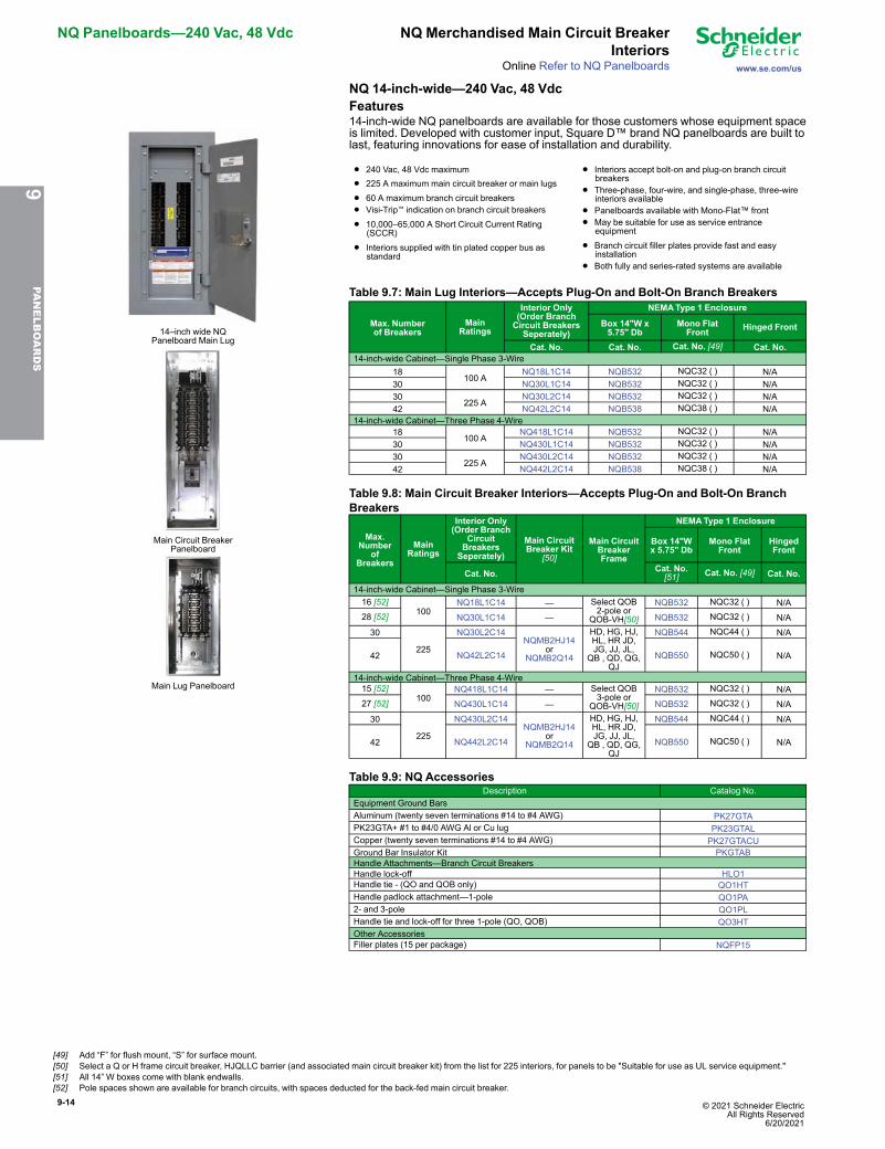
NQ 14-inch-wide—240 Vac, 48 VdcFeatures
14–inch wide NQPanelboard Main Lug
Main Circuit BreakerPanelboard
Main Lug Panelboard
14-inch-wide NQ panelboards are available for those customers whose equipment spaceis limited. Developed with customer input, Square D™ brand NQ panelboards are built tolast, featuring innovations for ease of installation and durability.
• 240 Vac, 48 Vdc maximum
• 225 A maximum main circuit breaker or main lugs
• 60 A maximum branch circuit breakers
• Visi-Trip™ indication on branch circuit breakers
• 10,000–65,000 A Short Circuit Current Rating(SCCR)
• Interiors supplied with tin plated copper bus asstandard
• Interiors accept bolt-on and plug-on branch circuitbreakers
• Three-phase, four-wire, and single-phase, three-wireinteriors available
• Panelboards available with Mono-Flat™ front
• May be suitable for use as service entranceequipment
• Branch circuit filler plates provide fast and easyinstallation
• Both fully and series-rated systems are available
Table 9.7: Main Lug Interiors—Accepts Plug-On and Bolt-On Branch Breakers
Max. Numberof Breakers
MainRatings
Interior Only(Order BranchCircuit BreakersSeperately)
NEMAType 1 Enclosure
Box 14"W x5.75" Db
Mono FlatFront Hinged Front
Cat. No. Cat. No. Cat. No. [49] Cat. No.14-inch-wide Cabinet—Single Phase 3-Wire
18100 A
NQ18L1C14 NQB532 NQC32 ( ) N/A30 NQ30L1C14 NQB532 NQC32 ( ) N/A30
225 ANQ30L2C14 NQB532 NQC32 ( ) N/A
42 NQ42L2C14 NQB538 NQC38 ( ) N/A14-inch-wide Cabinet—Three Phase 4-Wire
18100 A
NQ418L1C14 NQB532 NQC32 ( ) N/A30 NQ430L1C14 NQB532 NQC32 ( ) N/A30
225 ANQ430L2C14 NQB532 NQC32 ( ) N/A
42 NQ442L2C14 NQB538 NQC38 ( ) N/A
Table 9.8: Main Circuit Breaker Interiors—Accepts Plug-On and Bolt-On BranchBreakers
Max.Number
ofBreakers
MainRatings
Interior Only(Order Branch
CircuitBreakersSeperately)
Main CircuitBreaker Kit
[50]
Main CircuitBreakerFrame
NEMAType 1 Enclosure
Box 14"Wx 5.75" Db
Mono FlatFront
HingedFront
Cat. No. Cat. No.[51] Cat. No. [49] Cat. No.
14-inch-wide Cabinet—Single Phase 3-Wire16 [52]
100NQ18L1C14 — Select QOB
2-pole orQOB-VH[50]
NQB532 NQC32 ( ) N/A28 [52] NQ30L1C14 — NQB532 NQC32 ( ) N/A
30
225
NQ30L2C14NQMB2HJ14
orNQMB2Q14
HD, HG, HJ,HL, HR JD,JG, JJ, JL,
QB , QD, QG,QJ
NQB544 NQC44 ( ) N/A
42 NQ42L2C14 NQB550 NQC50 ( ) N/A
14-inch-wide Cabinet—Three Phase 4-Wire15 [52]
100NQ418L1C14 — Select QOB
3-pole orQOB-VH[50]
NQB532 NQC32 ( ) N/A27 [52] NQ430L1C14 — NQB532 NQC32 ( ) N/A
30
225
NQ430L2C14NQMB2HJ14
orNQMB2Q14
HD, HG, HJ,HL, HR JD,JG, JJ, JL,
QB , QD, QG,QJ
NQB544 NQC44 ( ) N/A
42 NQ442L2C14 NQB550 NQC50 ( ) N/A
Table 9.9: NQ AccessoriesDescription Catalog No.
Equipment Ground BarsAluminum (twenty seven terminations #14 to #4 AWG) PK27GTAPK23GTA+ #1 to #4/0 AWG Al or Cu lug PK23GTALCopper (twenty seven terminations #14 to #4 AWG) PK27GTACUGround Bar Insulator Kit PKGTABHandle Attachments—Branch Circuit BreakersHandle lock-off HLO1Handle tie - (QO and QOB only) QO1HTHandle padlock attachment—1-pole QO1PA2- and 3-pole QO1PLHandle tie and lock-off for three 1-pole (QO, QOB) QO3HTOther AccessoriesFiller plates (15 per package) NQFP15
9PA
NELBOARDS
[49] Add “F” for flush mount, “S” for surface mount.[50] Select a Q or H frame circuit breaker, HJQLLC barrier (and associated main circuit breaker kit) from the list for 225 interiors, for panels to be "Suitable for use as UL service equipment."[51] All 14” W boxes come with blank endwalls.[52] Pole spaces shown are available for branch circuits, with spaces deducted for the back-fed main circuit breaker.
© 2021 Schneider Electric All Rights Reserved6/20/2021
9-15
www.se.com/us
QOB Circuit Breakers for NQ Panelboards NQ Panelboards—240 Vac, 48 VdcOnline Refer to NQ Panelboards
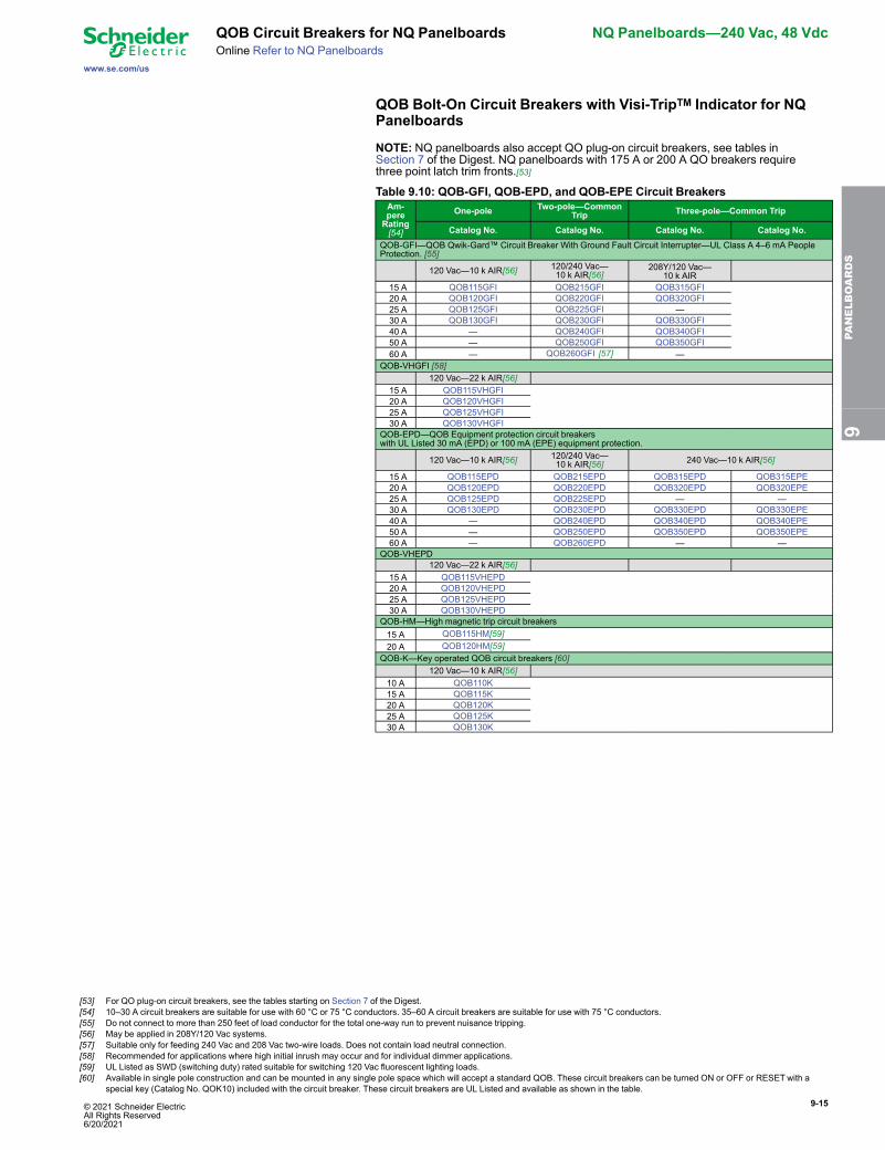
QOB Bolt-On Circuit Breakers with Visi-TripTM Indicator for NQPanelboards
NOTE: NQ panelboards also accept QO plug-on circuit breakers, see tables inSection 7 of the Digest. NQ panelboards with 175 A or 200 A QO breakers requirethree point latch trim fronts.[53]
Table 9.10: QOB-GFI, QOB-EPD, and QOB-EPE Circuit BreakersAm-pereRating[54]
One-pole Two-pole—CommonTrip Three-pole—Common Trip
Catalog No. Catalog No. Catalog No. Catalog No.QOB-GFI—QOB Qwik-Gard™ Circuit Breaker With Ground Fault Circuit Interrupter—UL Class A 4–6 mA PeopleProtection. [55]
120 Vac—10 k AIR[56] 120/240 Vac—10 k AIR[56]
208Y/120 Vac—10 k AIR
15 A QOB115GFI QOB215GFI QOB315GFI 20 A QOB120GFI QOB220GFI QOB320GFI 25 A QOB125GFI QOB225GFI — 30 A QOB130GFI QOB230GFI QOB330GFI 40 A — QOB240GFI QOB340GFI 50 A — QOB250GFI QOB350GFI 60 A — QOB260GFI [57] —QOB-VHGFI [58]
120 Vac—22 k AIR[56] 15 A QOB115VHGFI 20 A QOB120VHGFI 25 A QOB125VHGFI 30 A QOB130VHGFIQOB-EPD—QOB Equipment protection circuit breakerswith UL Listed 30 mA (EPD) or 100 mA (EPE) equipment protection.
120 Vac—10 k AIR[56] 120/240 Vac—10 k AIR[56] 240 Vac—10 k AIR[56]
15 A QOB115EPD QOB215EPD QOB315EPD QOB315EPE 20 A QOB120EPD QOB220EPD QOB320EPD QOB320EPE 25 A QOB125EPD QOB225EPD — — 30 A QOB130EPD QOB230EPD QOB330EPD QOB330EPE 40 A — QOB240EPD QOB340EPD QOB340EPE 50 A — QOB250EPD QOB350EPD QOB350EPE 60 A — QOB260EPD — —QOB-VHEPD
120 Vac—22 k AIR[56] 15 A QOB115VHEPD 20 A QOB120VHEPD 25 A QOB125VHEPD 30 A QOB130VHEPDQOB-HM—High magnetic trip circuit breakers15 A QOB115HM[59]20 A QOB120HM[59]
QOB-K—Key operated QOB circuit breakers [60]120 Vac—10 k AIR[56]
10 A QOB110K15 A QOB115K20 A QOB120K25 A QOB125K30 A QOB130K
9PA
NELBOARDS
[53] For QO plug-on circuit breakers, see the tables starting on Section 7 of the Digest.[54] 10–30 A circuit breakers are suitable for use with 60 °C or 75 °C conductors. 35–60 A circuit breakers are suitable for use with 75 °C conductors.[55] Do not connect to more than 250 feet of load conductor for the total one-way run to prevent nuisance tripping.[56] May be applied in 208Y/120 Vac systems.[57] Suitable only for feeding 240 Vac and 208 Vac two-wire loads. Does not contain load neutral connection.[58] Recommended for applications where high initial inrush may occur and for individual dimmer applications.[59] UL Listed as SWD (switching duty) rated suitable for switching 120 Vac fluorescent lighting loads.[60] Available in single pole construction and can be mounted in any single pole space which will accept a standard QOB. These circuit breakers can be turned ON or OFF or RESET with a
special key (Catalog No. QOK10) included with the circuit breaker. These circuit breakers are UL Listed and available as shown in the table.
9-16 © 2021 Schneider Electric All Rights Reserved
6/20/2021
NQ Panelboards—240 Vac, 48 Vdc QOB Circuit Breakers for NQ Panelboards
www.se.com/us
Online Refer to NQ Panelboards
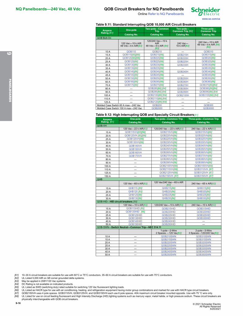
Table 9.11: Standard Interrupting QOB 10,000 AIR Circuit Breakers
AmpereRating [61]
One-pole Two-pole—CommonTrip
Two-pole—Common Trip [62]
Three-pole—Common Trip
Catalog No. Catalog No. Catalog No. Catalog No.QOB Bolt-On
120 Vac—10 k AIR48 Vdc—5 k AIR[63]
120/240 Vac—10 kAIR
48 Vdc—5 k AIR [64][63]
240 Vac—10 k AIR[63]
240 Vac—10 k AIR48 Vdc—5 k AIR [64]
[63]
10 A QOB110 QOB210 — QOB310 15 A QOB115[65][66] QOB215[66] QOB215H QOB315[66] 20 A QOB120[65][66] QOB220[66] QOB220H QOB320[66] 25 A QOB125[66] QOB225[66] QOB225H QOB325[66] 30 A QOB130[66] QOB230[66] QOB230H QOB330[66] 35 A QOB135[66] QOB235[66] — QOB335[66] 40 A QOB140[66] QOB240[66] QOB240H QOB340[66] 45 A QOB145[66] QOB245[66] — QOB345[66] 50 A QOB150[66] QOB250[66] QOB250H QOB350[66] 60 A QOB160[66] QOB260[66] QOB260H QOB360[66] 70 A QOB170[66] QOB270[66] QOB270H QOB370[66][64] 80 A — QOB280[66] [64] QOB280H QOB380[66][64] 90 A — QOB290[66] [64] QOB290H QOB390[66] [64]100 A — QOB2100[66] [64] QOB2100H QOB3100[66] [64]110 A — QOB2110[66] [64] — —125 A — QOB2125[66] [64] — —
Molded Case Switch 60 A max—240 Vac QOB200 — QOB300Molded Case Switch 100 A max—240 Vac QOB2000 — QOB3000
Table 9.12: High Interrupting QOB and Specialty Circuit Breakers[61]Ampere
Rating [61]One-pole Two-pole—Common Trip Three-pole—Common Trip
Catalog No. Catalog No. Catalog No.QOB-VH
120 Vac—22 k AIR[63] 120/240 Vac —22 k AIR[63] 240 Vac—22 k AIR[63] 15 A QOB115VH[65][66] QOB215VH[66] QOB315VH[66] 20 A QOB120VH [65][66] QOB220VH[66] QOB320VH[66] 25 A QOB125VH[66] QOB225VH[66] QOB325VH[66] 30 A QOB130VH[66] QOB230VH[66] QOB330VH[66] 40 A QOB140VH QOB240VH[66] QOB340VH[66] 50 A QOB150VH QOB250VH[66] QOB350VH[66] 60 A QOB160VH QOB260VH[66] QOB360VH[66] 70 A QOB170VH QOB270VH[66] QOB370VH[66] 80 A — QOB280VH[66] QOB380VH[66] 90 A — QOB290VH[66] QOB390VH[66]100 A — QOB2100VH[66] QOB3100VH[66]110 A — QOB2110VH[66] QOB3110VH [67]125 A — QOB2125VH[66] QOB3125VH [67]150 A — QOB2150VH [67] QOB3150VH [67]
QHB
120 Vac—65 k AIR[63] 120 Vac/240 Vac—65 k AIR[63] 240 Vac—65 k AIR[63]
15 A QHB115 [65] QHB215[66] QHB315[66] 20 A QHB120 [65] QHB220[66] QHB320[66] 25 A QHB125[66] QHB225[66] QHB325[66] 30 A QHB130[66] QHB230[66] QHB330[66]
QOB-HID—HID circuit breakers [68]120 Vac—10 k AIR[63] 120/240 Vac—10 k AIR[63] 240 Vac—10 k AIR[63]
15 A QOB115HID [65] QOB215HID QOB315HID 20 A QOB120HID [65] QOB220HID QOB320HID 25 A QOB125HID QOB225HID QOB325HID 30 A QOB130HID QOB230HID QOB330HID 40 A QOB140HID QOB240HID — 50 A QOB150HID QOB250HID —
QOB-SWN—Switch Neutral—Common Trip—NEC 514.111-pole—2-Wire
2 Spaces —120 Vac[63]2-pole—3-Wire
3 Spaces—120/240 Vac[63]10 A — QOB210SWN QOB310SWN15 A — QOB215SWN QOB315SWN20 A — QOB220SWN QOB320SWN25 A — QOB225SWN QOB325SWN30 A — QOB230SWN QOB330SWN40 A — QOB240SWN QOB340SWN50 A — QOB250SWN QOB350SWN
9PA
NELBOARDS
[61] 10–30 A circuit breakers are suitable for use with 60°C or 75°C conductors. 35–60 A circuit breakers are suitable for use with 75°C conductors.[62] UL Listed 5,000 AIR on 3Ø corner grounded delta systems.[63] May be applied in 208Y/120 Vac systems.[64] DC Rating is not available on indicated products.[65] UL Listed as SWD (switching duty) rated suitable for switching 120 Vac fluorescent lighting loads.[66] UL Listed as HACR type for use with air conditioning, heating, and refrigeration equipment having motor group combinations and marked for use with HACR type circuit breakers.[67] QOB2150VH uses 4 pole spaces. QOB3110VH, QOB3125VH, and QOB3150VH each use 6 pole spaces. 40A maximum circuit breaker mounted opposite. Use with 75 °C wire only.[68] UL Listed for use on circuit feeding fluorescent and High Intensity Discharge (HID) lighting systems such as mercury vapor, metal halide, or high pressure sodium. These circuit breakers are
physically interchangeable with QOB circuit breakers.
© 2021 Schneider Electric All Rights Reserved6/20/2021
9-17
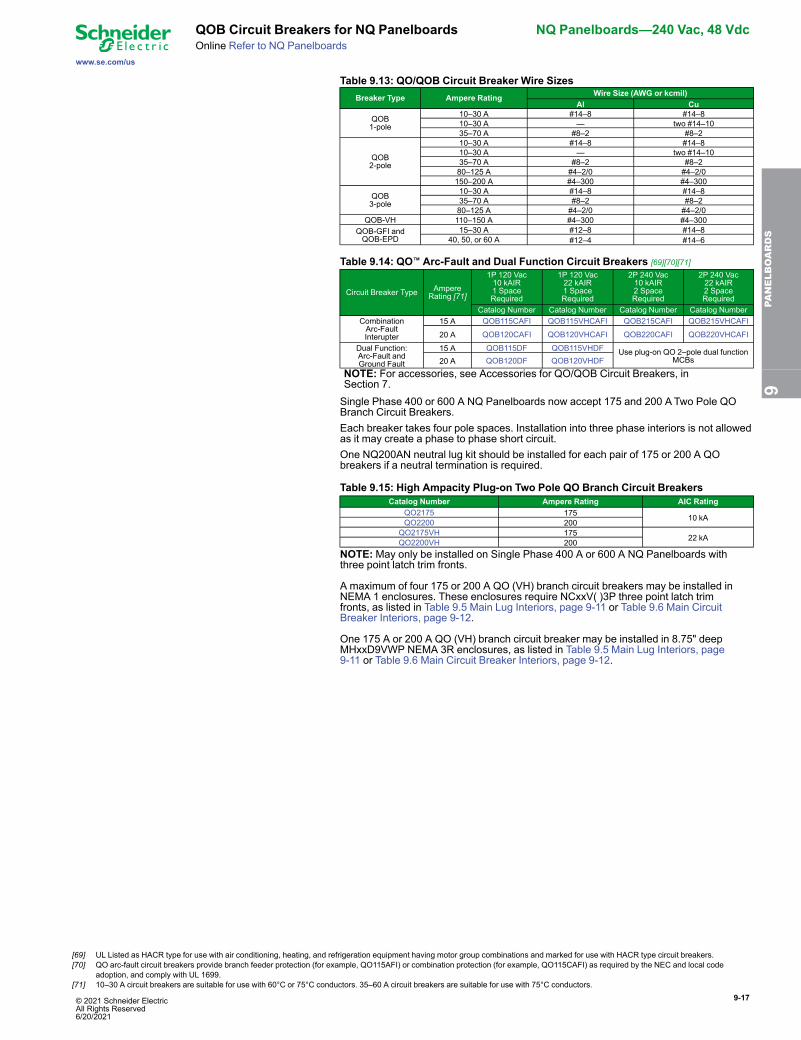
www.se.com/us
QOB Circuit Breakers for NQ Panelboards NQ Panelboards—240 Vac, 48 VdcOnline Refer to NQ Panelboards
Table 9.13: QO/QOB Circuit Breaker Wire SizesBreaker Type Ampere Rating Wire Size (AWG or kcmil)
Al Cu
QOB1-pole
10–30 A #14–8 #14–810–30 A — two #14–1035–70 A #8–2 #8–2
QOB2-pole
10–30 A #14–8 #14–810–30 A — two #14–1035–70 A #8–2 #8–280–125 A #4–2/0 #4–2/0150–200 A #4–300 #4–300
QOB3-pole
10–30 A #14–8 #14–835–70 A #8–2 #8–280–125 A #4–2/0 #4–2/0
QOB-VH 110–150 A #4–300 #4–300QOB-GFI andQOB-EPD
15–30 A #12–8 #14–840, 50, or 60 A #12–4 #14–6
Table 9.14: QO™ Arc-Fault and Dual Function Circuit Breakers [69][70][71]
Circuit Breaker Type AmpereRating [71]
1P 120 Vac10 kAIR1 SpaceRequired
1P 120 Vac22 kAIR1 SpaceRequired
2P 240 Vac10 kAIR2 SpaceRequired
2P 240 Vac22 kAIR2 SpaceRequired
Catalog Number Catalog Number Catalog Number Catalog NumberCombinationArc-FaultInterupter
15 A QOB115CAFI QOB115VHCAFI QOB215CAFI QOB215VHCAFI
20 A QOB120CAFI QOB120VHCAFI QOB220CAFI QOB220VHCAFI
Dual Function:Arc-Fault andGround Fault
15 A QOB115DF QOB115VHDF Use plug-on QO 2–pole dual functionMCBs20 A QOB120DF QOB120VHDF
NOTE: For accessories, see Accessories for QO/QOB Circuit Breakers, inSection 7.Single Phase 400 or 600 A NQ Panelboards now accept 175 and 200 ATwo Pole QOBranch Circuit Breakers.Each breaker takes four pole spaces. Installation into three phase interiors is not allowedas it may create a phase to phase short circuit.One NQ200AN neutral lug kit should be installed for each pair of 175 or 200 A QObreakers if a neutral termination is required.
Table 9.15: High Ampacity Plug-on Two Pole QO Branch Circuit BreakersCatalog Number Ampere Rating AIC Rating
QO2175 175 10 kAQO2200 200QO2175VH 175 22 kAQO2200VH 200
NOTE:May only be installed on Single Phase 400 A or 600 A NQ Panelboards withthree point latch trim fronts.
A maximum of four 175 or 200 A QO (VH) branch circuit breakers may be installed inNEMA 1 enclosures. These enclosures require NCxxV( )3P three point latch trimfronts, as listed in Table 9.5 Main Lug Interiors, page 9-11 or Table 9.6 Main CircuitBreaker Interiors, page 9-12.
One 175 A or 200 A QO (VH) branch circuit breaker may be installed in 8.75" deepMHxxD9VWP NEMA 3R enclosures, as listed in Table 9.5 Main Lug Interiors, page9-11 or Table 9.6 Main Circuit Breaker Interiors, page 9-12.
9PA
NELBOARDS
[69] UL Listed as HACR type for use with air conditioning, heating, and refrigeration equipment having motor group combinations and marked for use with HACR type circuit breakers.[70] QO arc-fault circuit breakers provide branch feeder protection (for example, QO115AFI) or combination protection (for example, QO115CAFI) as required by the NEC and local code
adoption, and comply with UL 1699.[71] 10–30 A circuit breakers are suitable for use with 60°C or 75°C conductors. 35–60 A circuit breakers are suitable for use with 75°C conductors.
9-18 © 2021 Schneider Electric All Rights Reserved
6/20/2021
NQ Panelboards—240 Vac, 48 Vdc NQ Factory Assembled Panelboards
www.se.com/us
NQ Main and Sub-feed Circuit Breakers
Factory Assembled Main Circuit Breakers400 A and 600 A panelboards, 1Ø or 3Ø
Table 9.16: NQ Panelboard Factory Assembled Interiors - 240 Vac / 48 Vdc MaxSingle Phase or Three Phase
Mains Rating (Amps)Max. Number ofOne-Pole Circuit
BreakersBus
Material
Min. Box Depth
Main LugsOnly
MainCircuit
Breaker[72]Main Switch
[72]Main Lugs
OnlyMain
Circuit Breaker /Switch
100 Max 15–100 70–100 18, 30 Al, Cu 5.75 in. 5.75 in.225 Max 15–250 110–250 30, 42, 54, 72, 84 Al, Cu 5.75 in. 5.75 in.
400 Max 125–400 300–400 30, 42, 54, 72[73],84[74] Al, Cu 5.75 in. 5.75 in. / 8.75 in.
[75]
600 Max 125–600 450–600 30, 42, 54, 72[73],84 Cu 5.75 in. 8.75 in.[75]
Table 9.17: Main Circuit Breaker (PowerPacT L-frame - see PowerPacT InterruptingRatings, and Common Catalog Numbering System, in Section 7)
Number of Poles Trip Unit Options Frame Sizes Ampacity3 LI, LSI, Switch LG, LJ, LL 125–600 A
LA/LH PowerPacT H, J, and Q-frame circuit breakers are also available - see TablesPowerPact Interrupting Ratings, page and Common Catalog Numbering System,page and Supplemental Digest Section 3.
Table 9.18: PowerPacT L Main Circuit Breaker Cabinet Height (inches)[76]Max. No. of Branch Spaces(Does not include sub-feedcircuit breaker spaces)
NEMA 1 Enclosure(20 in. W x 8.75 in. D)[77]
Vented NEMA 3R Enclosure(26 in. W x 8.75 in. D)[76]
400 or 600 A 400 A 600 A30 62 62 6842 68 68 7454 74 74 8072 80 – –84 86 – –
Sub-feed Circuit BreakersMain lugs or main circuit breaker interior—1Ø or 3Ø.Maximum 1 circuit breaker per 225 A main lug or 250 A main circuit breaker panelboard,2 circuit breakers per 400–600 A panelboard.Panelboards in MHxxWP NEMAType 3R/5/12 enclosures are limited to one 150 Amaximum sub-feed breaker.
Table 9.19: Sub-feed Circuit Breaker (see PowerPacT Interrupting Ratings, andCommon Catalog Numbering System, in Section 7)Panelboard Mains
RatingSub Feed Breaker Space Factor (in.)[78]
No. of Poles Ampacity MCCB Frame
225 A
2 70–225 QB, QD, QG, QJ 1832 110–150 HD, HG, HJ, HL, HR 1832 150–225 JD, JG, JJ, JL, JR 183
400 A, 600 A
2 70–225 QB, QD, QG, QJ 2432 110–150 HD, HG, HJ, HL, HR 2432 150–225 JD, JG, JJ, JL, JR 243
400 A 3 126–600 LG, LJ, LL 18600 APowerPacT H, J, & L frame circuit breakers are also available - see Tables PowerPacT Interrupting Ratings, andCommon Catalog Numbering System, Section 7.
Table 9.20: PowerPacT H, J, or Q-frame Sub-feed Circuit Breaker Cabinet Height(inches)
Max. No. of Branch Spaces(Does not include
sub-feedcircuit breaker spaces)
Standard Depth Enclosures(20 in. W x 5.75 in. D)225 A 250 A 400 A 600 AMainLugs
Main CircuitBreaker
MainLugs[79]
LA / LH MainCircuitBreaker
MainLugs[79]
30 50 62 74 86 7442 56 68 74 86 8054 62 74 80 92 8072 68 80 86 – 8684 74 86 92 – 92
9PA
NELBOARDS
[72] Factory Assembled Interiors are rated for trip current of Main Breaker / Switch.[73] Three Phase only.[74] Copper only.[75] Deep Box required for PowerPacT L Main Circuit Breaker or Switch.[76] Feed-thru lugs and compression lugs available factory assembled only. These add 6 - 12 inches to enclosure length.[77] D9 8.75" deep enclosures are required for PowerPacT L Main Circuit Breaker, Switch, or Sub-Feed Circuit Breaker.[78] Space Factor - add this length to enclosure when adding a Sub Feed Breaker.[79] Bottom feed only in NEMA 3R enclosures.
© 2021 Schneider Electric All Rights Reserved6/20/2021
9-19
www.se.com/us
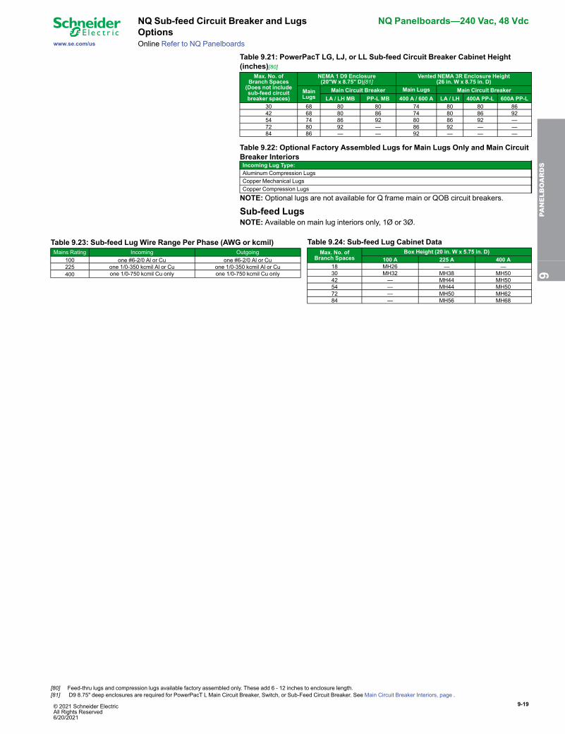
NQ Sub-feed Circuit Breaker and LugsOptions
NQ Panelboards—240 Vac, 48 Vdc
Online Refer to NQ Panelboards
Table 9.21: PowerPacT LG, LJ, or LL Sub-feed Circuit Breaker Cabinet Height(inches)[80]
Max. No. ofBranch Spaces(Does not includesub-feed circuitbreaker spaces)
NEMA 1 D9 Enclosure(20"W x 8.75" D)[81]
Vented NEMA 3R Enclosure Height(26 in. W x 8.75 in. D)
MainLugs
Main Circuit Breaker Main Lugs Main Circuit BreakerLA / LH MB PP-L MB 400 A / 600 A LA / LH 400A PP-L 600A PP-L
30 68 80 80 74 80 80 8642 68 80 86 74 80 86 9254 74 86 92 80 86 92 —72 80 92 — 86 92 — —84 86 — — 92 — — —
Table 9.22: Optional Factory Assembled Lugs for Main Lugs Only and Main CircuitBreaker InteriorsIncoming Lug Type:Aluminum Compression LugsCopper Mechanical LugsCopper Compression Lugs
NOTE: Optional lugs are not available for Q frame main or QOB circuit breakers.
Sub-feed LugsNOTE: Available on main lug interiors only, 1Ø or 3Ø.
Table 9.23: Sub-feed Lug Wire Range Per Phase (AWG or kcmil)Mains Rating Incoming Outgoing
100 one #6-2/0 Al or Cu one #6-2/0 Al or Cu225 one 1/0-350 kcmil Al or Cu one 1/0-350 kcmil Al or Cu400 one 1/0-750 kcmil Cu only one 1/0-750 kcmil Cu only
Table 9.24: Sub-feed Lug Cabinet DataMax. No. of
Branch SpacesBox Height (20 in. W x 5.75 in. D)
100 A 225 A 400 A18 MH26 — —30 MH32 MH38 MH5042 — MH44 MH5054 — MH44 MH5072 — MH50 MH6284 — MH56 MH68
9PA
NELBOARDS
[80] Feed-thru lugs and compression lugs available factory assembled only. These add 6 - 12 inches to enclosure length.[81] D9 8.75" deep enclosures are required for PowerPacT L Main Circuit Breaker, Switch, or Sub-Feed Circuit Breaker. See Main Circuit Breaker Interiors, page .
9-20 © 2021 Schneider Electric All Rights Reserved
6/20/2021
NQ Panelboards—240 Vac, 48 Vdc NQ Feed-through Lugs, NeutralAssemblies, & Factory Assembled Options
www.se.com/usOnline Refer to NQ Panelboards
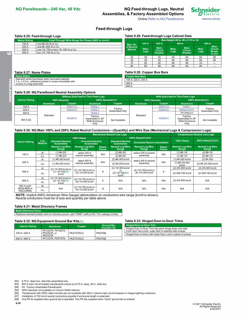
Feed-through Lugs
Table 9.25: Feed-through LugsMains Rating Feed-Through Wire Range Per Phase (AWG or kcmil)
100 A one #6-2/0 Al or Cu225 A one #6–350 Al or Cu400 A one 1/0–750 or two 1/0–350 Al or Cu600 A two 1/0–750 Al or Cu
Table 9.26: Feed-through Lugs Cabinet Data
Max. No.of BranchSpaces
Box Height (20 in. W x 5.75 in. D)225 A 250 A 400 A 600 A
MainLugs
MainCircuitBreaker
MainLugs
MainCircuitBreaker
MainLugs
MainCircuitBreak-er [82]
30 38 50 50 62 62 6842 38 50 56 68 62 8072 50 62 68 80 74 —84 56 68 68 80 80 —
Table 9.27: Name PlatesName PlatesStandard white face/black letter laminated bakelite,1 in. x 3.5 in., adhesive backed or screw mountable withscrews in a bag assembly
Table 9.28: Copper Bus BarsCopper Bus Bars100 A, 225 A, 250 A400 A600 A
Table 9.29: NQ Panelboard Neutral Assembly Options
Interior RatingWithout Sub-Feed or Thru-Feed Lugs With Sub-Feed or Thru-Feed Lugs
100% Neutrals 200% Neutrals[83] 100% Neutrals 200% Neutrals[83]Aluminum Copper Aluminum Copper Aluminum Copper Aluminum Copper
100 A
Standard
NQN1CU NQNL1Factory
Assembled Only
Standard
NQN1CU NQNL1Factory
Assembled Only225 A NQN2CU NQNL2 NQN2CU NQNL2ACCY400 A
NQN6CU
NQNL4
NQN6CU
FA Only[84]
600 A [3]Factory
Assembled in 26"Wide Enclosure
OnlyNot Available
FactoryAssembled in 26"Wide Enclosure
OnlyNot Available
Table 9.30: NQ Main 100% and 200% Rated Neutral Conductors—(Quantity) and Wire Size (Mechanical Lugs & Compression Lugs)
Interior Rating LugMaterial
Mechanical Neutral Line Lugs Compression Neutral Line Lugs100% Rated 200% Rated[85][86]
100% Rated 200% Rated[85][86]Standard NeutralAssemblies
Oversized NeutralAssemblies
Standard NeutralAssemblies Oversized Neutral Assemblies
Neutral Lug WireRange
Neutral Lug WireRange
SpaceFactor
Neutral Lug WireRange
Neutral Lug WireRange
SpaceFactor
Neutral Lug WireRange
Neutral Lug WireRange
100 AAl (1) #6-2/0 select 225 A
neutral assembly N/A(2) #6-2/0 select 225 A neutral
assembly N/A(1) #8-1/0 (2) #8-1/0
Cu (1) #6-2/0 (2) #6-2/0 (1) #6-1/0 (2) #6-1/0
225 AAl (1) #6-300 kcmil select 400 A
neutral assembly N/A(2) #6-300 kcmil select 400 A neutral
assembly N/A(1) #4-300 kcmil (2) #4-300
Cu (1) #6-250 kcmil (2) #6-250 kcmil (1) #6 2/0-300kcmil (2) #6 2/0-300 kcmil
400 AAl (2) 1/0-300 kcmil or
(1) 1/0-750[87]kcmil
(2) 1/0-750 kcmil or(4) 1/0-300 kcmil 6
(4) 1/0-300 kcmilor
(2) 1/0-750[87]kcmil
(4) 1/0-750 kcmil or(8) 1/0-300 kcmil 6
(2) 2/0-500 kcmil (4) 2/0-500 kcmil
Cu (2) 400-750 kcmil (4) 400-750 kcmil
600 AAl (4) 1/0-300 kcmil or
(2) 1/0-750[87]kcmil
(4) 1/0-750 kcmil or(8) 1/0-300 kcmil 6 N/A N/A N/A (2) 2/0-500 kcmil N/ACu
600 A (withNQALMN6 orNQCUMN6)
AlN/A (2) 1/0-750 kcmil or
(4) 1/0-300 kcmil 12 N/A N/A N/A N/A N/ACu
NOTE: Implicit AWG (American Wire Gauge) abbreviation on conductors wire range (kcmil is shown).Neutral conductors must be of size and quantity per table above.
Table 9.31: Metal Directory FramesMetal Directory FrameReplaces standard plastic stick-on directory pouch, add "WMD" suffix to NC Trim catalog number.
Table 9.32: NQ Equipment Ground Bar Kits[88]Interior Rating Aluminum Copper Ground Bar
Insulator Kit
100 A / 225 APK12GTA, PK18GTA,PK23GTA, orPK27GTA
PK27GTACU PKGTAB
400 A / 600 A PK12GTA, PK27GTA PK27GTACU PKGTAB
Table 9.33: Hinged Door-in-Door TrimsHinged Door-in-Door TrimHinged Door-in-Door Trim has piano hinge down one side.Inner door has a lock, outer door is retained with screwsHinged Door-in-Door with Outer Door Lock in place of screws
9PA
NELBOARDS
[82] 8.75 in. deep box, ship fully assembled only.[83] 600 A main circuit breaker panelboards require an 8.75 in. deep, 26 in. wide box.[84] FA - Factory Assembled Panelboards[85] 200% Neutrals not available on Column Width interiors.[86] Panelboards with 200% rated neutrals are not available with 250 A J-frame main circuit breakers or integral lighting contactors.[87] Installation of 750 kcmil neutral conductors possible if enclosure length is extended.[88] One PK kit supplied when ground bar is specified. Two PK kits supplied when "extra" ground bar is ordered.
© 2021 Schneider Electric All Rights Reserved6/20/2021
9-21
www.se.com/us
NQ Surge Protective NQ Panelboards—240 Vac, 48 VdcOnline Refer to NQ Panelboards
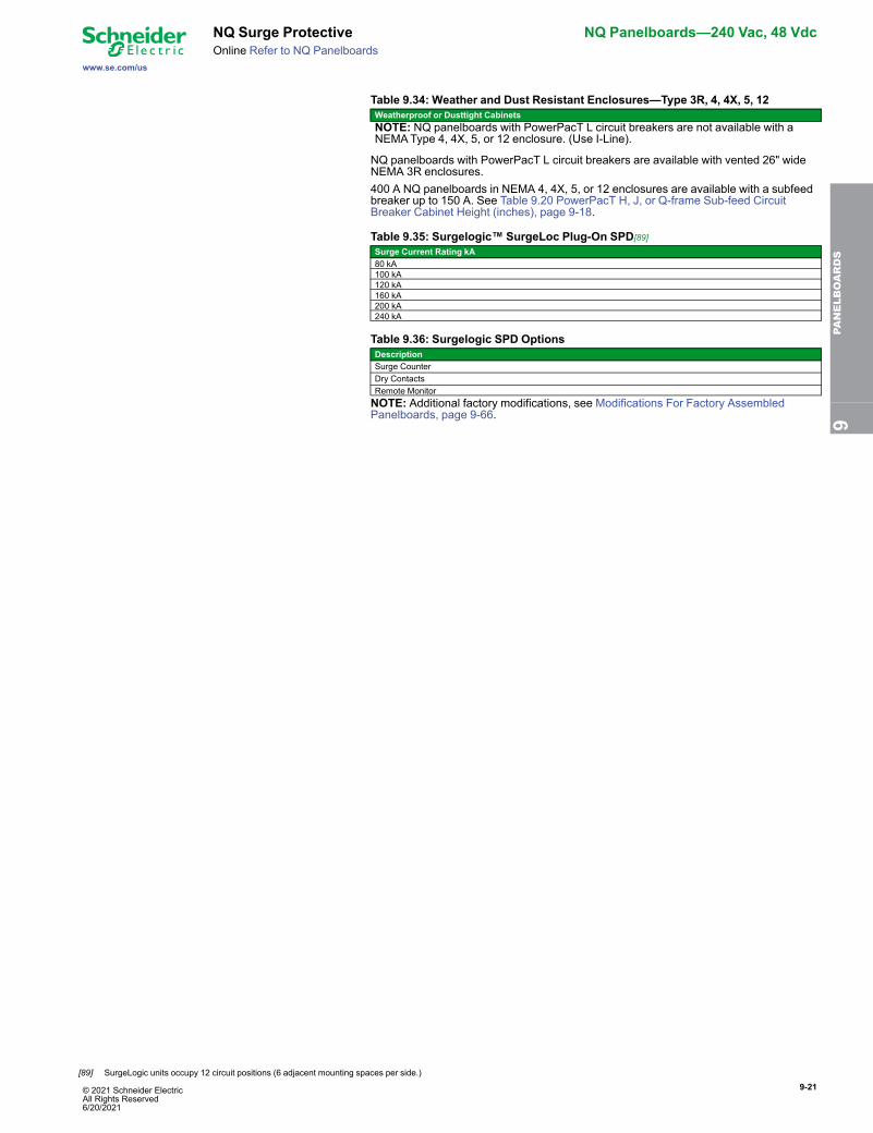
Table 9.34: Weather and Dust Resistant Enclosures—Type 3R, 4, 4X, 5, 12Weatherproof or Dusttight CabinetsNOTE: NQ panelboards with PowerPacT L circuit breakers are not available with aNEMAType 4, 4X, 5, or 12 enclosure. (Use I-Line).
NQ panelboards with PowerPacT L circuit breakers are available with vented 26" wideNEMA 3R enclosures.400 A NQ panelboards in NEMA 4, 4X, 5, or 12 enclosures are available with a subfeedbreaker up to 150 A. See Table 9.20 PowerPacT H, J, or Q-frame Sub-feed CircuitBreaker Cabinet Height (inches), page 9-18.
Table 9.35: Surgelogic™ SurgeLoc Plug-On SPD[89]Surge Current Rating kA80 kA100 kA120 kA160 kA200 kA240 kA
Table 9.36: Surgelogic SPD OptionsDescriptionSurge CounterDry ContactsRemote MonitorNOTE: Additional factory modifications, see Modifications For Factory AssembledPanelboards, page 9-66. 9
PANELBOARDS
[89] SurgeLogic units occupy 12 circuit positions (6 adjacent mounting spaces per side.)
9-22 © 2021 Schneider Electric All Rights Reserved
6/20/2021
NQ Panelboards—240 Vac, 48 Vdc NQ Panelboard Accessories
www.se.com/us
Online Refer to NQ Panelboards
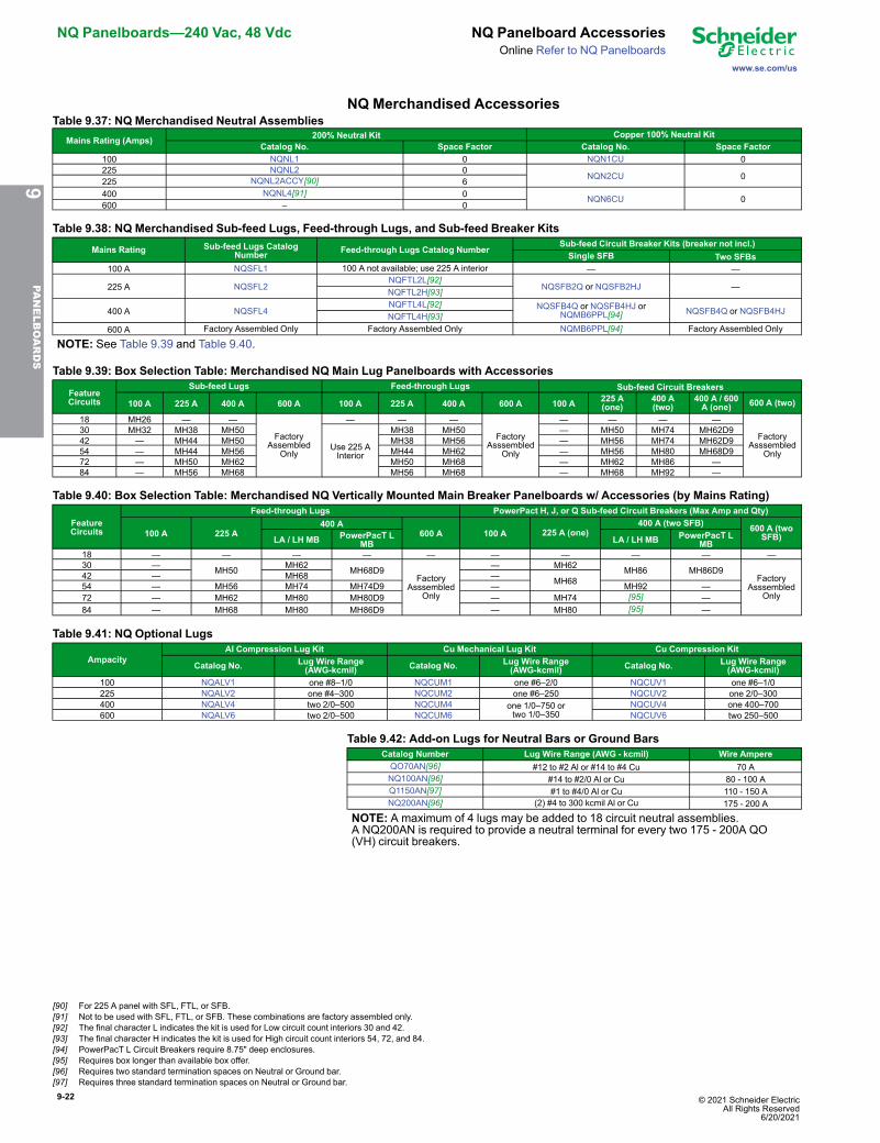
NQ Merchandised AccessoriesTable 9.37: NQ Merchandised Neutral Assemblies
Mains Rating (Amps) 200% Neutral Kit Copper 100% Neutral KitCatalog No. Space Factor Catalog No. Space Factor
100 NQNL1 0 NQN1CU 0225 NQNL2 0
NQN2CU 0225 NQNL2ACCY[90] 6400 NQNL4[91] 0 NQN6CU 0600 – 0
Table 9.38: NQ Merchandised Sub-feed Lugs, Feed-through Lugs, and Sub-feed Breaker Kits
Mains Rating Sub-feed Lugs CatalogNumber Feed-through Lugs Catalog Number
Sub-feed Circuit Breaker Kits (breaker not incl.)Single SFB Two SFBs
100 A NQSFL1 100 A not available; use 225 A interior — —
225 A NQSFL2NQFTL2L[92]
NQSFB2Q or NQSFB2HJ —NQFTL2H[93]
400 A NQSFL4NQFTL4L[92] NQSFB4Q or NQSFB4HJ or
NQMB6PPL[94] NQSFB4Q or NQSFB4HJNQFTL4H[93]600 A Factory Assembled Only Factory Assembled Only NQMB6PPL[94] Factory Assembled Only
NOTE: See Table 9.39 and Table 9.40.
Table 9.39: Box Selection Table: Merchandised NQ Main Lug Panelboards with Accessories
FeatureCircuits
Sub-feed Lugs Feed-through Lugs Sub-feed Circuit Breakers
100 A 225 A 400 A 600 A 100 A 225 A 400 A 600 A 100 A 225 A(one)
400 A(two)
400 A / 600A (one) 600 A (two)
18 MH26 — —
FactoryAssembled
Only
— — —
FactoryAsssembled
Only
— — — —
FactoryAsssembled
Only
30 MH32 MH38 MH50
Use 225 AInterior
MH38 MH50 — MH50 MH74 MH62D942 — MH44 MH50 MH38 MH56 — MH56 MH74 MH62D954 — MH44 MH56 MH44 MH62 — MH56 MH80 MH68D972 — MH50 MH62 MH50 MH68 — MH62 MH86 —84 — MH56 MH68 MH56 MH68 — MH68 MH92 —
Table 9.40: Box Selection Table: Merchandised NQ Vertically Mounted Main Breaker Panelboards w/ Accessories (by Mains Rating)
FeatureCircuits
Feed-through Lugs PowerPact H, J, or Q Sub-feed Circuit Breakers (Max Amp and Qty)
100 A 225 A400 A
600 A 100 A 225 A (one)400 A (two SFB) 600 A (two
SFB)LA / LH MB PowerPacT LMB LA / LH MB PowerPacT L
MB18 — — — — — — — — — —30 — MH50 MH62 MH68D9
FactoryAsssembled
Only
— MH62 MH86 MH86D9Factory
AsssembledOnly
42 — MH68 — MH6854 — MH56 MH74 MH74D9 — MH92 —72 — MH62 MH80 MH80D9 — MH74 [95] —84 — MH68 MH80 MH86D9 — MH80 [95] —
Table 9.41: NQ Optional Lugs
AmpacityAl Compression Lug Kit Cu Mechanical Lug Kit Cu Compression Kit
Catalog No. Lug Wire Range(AWG-kcmil) Catalog No. Lug Wire Range
(AWG-kcmil) Catalog No. Lug Wire Range(AWG-kcmil)
100 NQALV1 one #8–1/0 NQCUM1 one #6–2/0 NQCUV1 one #6–1/0225 NQALV2 one #4–300 NQCUM2 one #6–250 NQCUV2 one 2/0–300400 NQALV4 two 2/0–500 NQCUM4 one 1/0–750 or
two 1/0–350NQCUV4 one 400–700
600 NQALV6 two 2/0–500 NQCUM6 NQCUV6 two 250–500
Table 9.42: Add-on Lugs for Neutral Bars or Ground BarsCatalog Number Lug Wire Range (AWG - kcmil) Wire AmpereQO70AN[96] #12 to #2 Al or #14 to #4 Cu 70 ANQ100AN[96] #14 to #2/0 Al or Cu 80 - 100 AQ1150AN[97] #1 to #4/0 Al or Cu 110 - 150 ANQ200AN[96] (2) #4 to 300 kcmil Al or Cu 175 - 200 A
NOTE: A maximum of 4 lugs may be added to 18 circuit neutral assemblies.A NQ200AN is required to provide a neutral terminal for every two 175 - 200A QO(VH) circuit breakers.
9PA
NELBOARDS
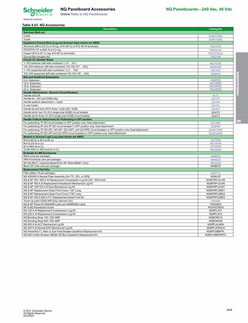
[90] For 225 A panel with SFL, FTL, or SFB.[91] Not to be used with SFL, FTL, or SFB. These combinations are factory assembled only.[92] The final character L indicates the kit is used for Low circuit count interiors 30 and 42.[93] The final character H indicates the kit is used for High circuit count interiors 54, 72, and 84.[94] PowerPacT L Circuit Breakers require 8.75" deep enclosures.[95] Requires box longer than available box offer.[96] Requires two standard termination spaces on Neutral or Ground bar.[97] Requires three standard termination spaces on Neutral or Ground bar.
© 2021 Schneider Electric All Rights Reserved6/20/2021
9-23
www.se.com/us
NQ Panelboard Accessories NQ Panelboards—240 Vac, 48 VdcOnline Refer to NQ Panelboards
Table 9.43: NQ AccessoriesDescription Catalog No.
Sub-feed (Bolt-on)2-pole QOB2125SL3-pole QOB3125SLEquipment Ground Bars (Lug and terminal sizes shown are AWG)Aluminum (#6 to 2/0 Cu or Al lug , #14–#4 Cu or #12–#4 Al terminals) PK27GTAPK23GTA+ #1 to #4/0 Al or Cu lug PK23GTALCopper (#14 to #1 Cu lug, #14-#4 Cu terminals) PK27GTACUGround Bar Insulator Kit PKGTABCircuit I.D. Number Strips1–102 odd/even (left side numbered 1,3,5 ...101) NQ102OE103–204 odd/even (left side numbered 103,105,107 ... 203) NQ204OE1–102 sequential (left side numbered 1,2,3 ... 102) NQ102S103–204 sequential (left side numbered 103,104,105 ... 204) NQ204SRail and Deadfront Extensions6 in. Extension NQ6RDE12 in. Extension NQ12RDE18 in. Extension NQ18RDE24 in. Extension NQ24RDEHandle Attachments—Branch Circuit BreakersHandle lock-off HLO1Handle tie - (QO and QOB only) QO1HTHandle padlock attachment—1-pole QO1PA2- and 3-pole QO1PLHandle tie and lock-off for three 1-pole (QO, QOB) QO3HTHandle tie for two 10–30 A single pole QO(B) circuit breaker QOHT2Handle tie for three 10–30 A single pole QO(B) circuit breaker QOHT3Handle Padlock Attachment for Padlocking in OFF positionFor padlocking 1P QO circuit breaker in OFF position only, fixed attachment QO1PAFFor padlocking 2P and 3P QO circuit breaker in OFF position only, fixed attachment QO2PAFFor padlocking 1P QO-GFI, QO-AFI, QO-CAFI, and QO-EPD circuit breakers in OFF position only, fixed attachment QOGFI1PAFFor padlocking 2P QO-GFI and QO-EPD circuit breakers in OFF position only, fixed attachment QOGFI2PAFNeutral or Ground Lugs (Lug sizes shown are AWG)#10 to #2 Al or #14 to #4 Cu QO70AN#14 to 2/0 Al or Cu NQ100AN#1 to #4/0 Al or Cu Q1150AN(2) #4 AWG to 300 kcmil Al or Cu NQ200ANEndwalls for MH EnclosuresBlank (one per package) MHBE20With Knockouts (one per package) MHKE20NF NQ RECT. Cutout Endwall Kit for 20" Wide NEMA 1 Encl. MHCO20Blank 26" wide (one per package) MHBE26Replacement Part KitsFiller plates (15 per package) NQFP15NQ 400/600 A Neutral Plate Assembly (for FTL, SFL, or SFB) NQNLEPNQ & NF 400 / 600 A Al Replacement Compression Lug Kit (2/0 - 500 kcmil) NQNFRPLALV46NQ & NF 400 A Al Replacement Panelboard Mechanical Lug Kit NQNFRPLALM4NQ & NF 100/125 A Al Dual Mechanical Lug Kit NQNFRPLALM1NQ & NF Replacement Dead Front Cover 1.65" Long NQNFRPL05601NQ & NF Replacement Dead Front Cover 7.58" Long NQNFRPL05603NQ & NF 400 A 600 A FTL Replacement Dead Front Kit NQNFRPL05603Touch-up paint USAS #49 Gray (Aerosol can) PK49SPNQ & NF Panel Kit DANGER Label and WARNING Label PKDGWGNF & NQ Panelboard Screw PKDFSCREWNQ 100 A Al Replacement Compression Lug Kit NQRPLAV1NQ 225 A Al Replacement Compression Lug Kit NQRPLAV2NQ Bonding Strap 100 / 225 AMP NQBOND12NQ Bonding Strap 400 / 600 AMP NQBOND46NQ 600 A Al ACC Mechanical Lug Kit NQRPLALM6ANQ 400 A Al Neutral EXP Mechanical Lug Kit NQRPLSFBALNNQ PowerPacT L Main or Sub Feed Breaker Deadfront Replacement Kit NQRPLMB6PPLNQ 600 A Main Breaker (NEMA 3R Box) Deadfront Replacement Kit NQRPLMB63RPPL
9PA
NELBOARDS
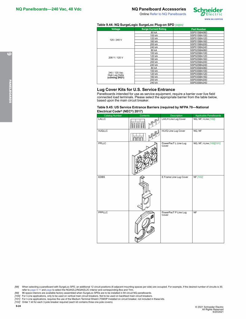
9-24 © 2021 Schneider Electric All Rights Reserved
6/20/2021
NQ Panelboards—240 Vac, 48 Vdc NQ Panelboard Accessories
www.se.com/us
Online Refer to NQ Panelboards
Table 9.44: NQ SurgeLogic SurgeLoc Plug-on SPD [98][99]Voltage Surge Current Rating Part Number
120 / 240 V
80 kA SSP01SBA08D100 kA SSP01SBA10D120 kA SSP01SBA12D160 kA SSP01SBA16D200 kA SSP01SBA20D240 kA SSP01SBA24D
208 Y / 120 V
80 kA SSP02SBA08D100 kA SSP02SBA10D120 kA SSP02SBA12D160 kA SSP02SBA16D200 kA SSP02SBA20D240 kA SSP02SBA24D
240 / 120 VacHigh Leg Delta(coming 2H21)
80 kA SSP03SBA08D100 kA SSP03SBA10D120 kA SSP03SBA12D160 kA SSP03SBA16D200 kA SSP03SBA20D240 kA SSP03SBA24D
Lug Cover Kits for U.S. Service EntrancePanelboards intended for use as service equipment, require a barrier over live fieldconnected load terminals. Please select the appropriate barrier from the table below,based upon the main circuit breaker.
Table 9.45: US Service Entrance Barriers (required by NFPA 70—NationalElectrical Code® (NEC®) 2017)
Catalog Number Contents Description Applicable PanelboardsLALLC LA/LH Line Lug Cover NQ, NF, I-Line [100]
HJQLLC H/J/Q Line Lug Cover NQ, NF
PPLLC PowerPacT L Line LugCover
NQ, NF, I-Line [100][101]
EDBS E Frame Line Lug Cover NF [102]
PPPLLC PowerPacT P Line LugCover
NF
9PA
NELBOARDS
[98] When selecting a panelboard with SurgeLoc SPD, an additional 12 circuit positions (6 adjacent mounting spaces per side) are occupied. For example, if the desired number of circuits is 30,refer to page 9-11 and page to select the NQ442L2/NQ442L2C interior and corresponding Box and Trim.
[99] 96 space interiors are available factory assembled when SurgeLoc SPDs are to be installed in 84 circuit NQ panelboards.[100] For I-Line applications, only to be used on vertical main circuit breakers. Not to be used on backfeed main circuit breakers.[101] For I-Line applications, requires the use of the Medium Terminal Shield LTSM3P Installed on circuit breaker, not included in these kits.[102] Order 1 kit for each 3 pole breaker required (each kit contains three one pole covers).
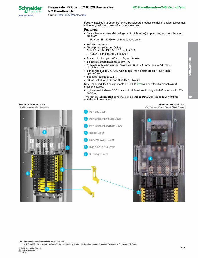
© 2021 Schneider Electric All Rights Reserved6/20/2021
9-25
www.se.com/us
Fingersafe IP2X per IEC 60529 Barriers forNQ Panelboards
NQ Panelboards—240 Vac, 48 Vdc
Online Refer to NQ Panelboards
Factory-installed IP2X barriers for NQ Panelboards reduce the risk of accidental contactwith energized components if a cover is removed.
Features• Plastic barriers cover Mains (lugs or circuit breaker), copper bus, and branch circuitbreakers– IP2X per IEC 60529 on all ungrounded parts
• 240 Vac maximum• Three phase (Wye and Delta)NEMA 1, 2, 3R, 4/4X, 5, or 12 (up to 225 A)– NEMA 1 panelboards up to 400 A
• Branch circuits up to 100 A: 1-, 2-, and 3-pole• Selectively coordinated up to 30k AIC• Available with main lugs, or PowerPacT Q-, H-, J-frame, and LA/LH maincircuit breakers
• Series rated up to 200 kAIC with integral main circuit breaker—fully ratedup to 65 kAIC
• Sub feed lugs up to 225 A• cULus Listed to UL 67 and CSA C22.2, No. 29New Enhanced IP2X design meets IEC 60529[103] with or without a branch circuitbreaker installed.• Unique jaw kit allows QOB branch circuit breakers to plug onto NQ interior with IP2Xbarriers
Two factory-assembled constructions (refer to Data Bulletin 1640BR1701 foradditional information):
Standard IP2X per IEC 60529 Enhanced IP2X per IEC 6052(Bus Finger Covers Empty Spaces) (Bus Covered Without Branch Circuit Breaker)
9PA
NELBOARDS
[103] International Electrotechnical Commission (IEC)a. IEC 60529: 1989+AMD1:1999+AMD2:2013 CSV Consolidated version.- Degrees of Protection Provided by Enclosures (IP Code)
9-26 © 2021 Schneider Electric All Rights Reserved
6/20/2021
NQ Panelboards—240 Vac, 48 Vdc Fingersafe IP2X per IEC 60529 Barriers forNQ Panelboards
www.se.com/usOnline Refer to NQ Panelboards
SpecificationsNQ Fingersafe Bus Ratings, Enclosures, and Circuit Counts
IP2XDesign
Mainsrating
Enclo-sures:NEMAtypes
Circuit Count
18 30 42 54 72 84
Standard100 1, 2, 3R,
4/4X, 5, 12X X — — — —
225 — X X X X X400 1 — X X — X X
Enhanced 225 1, 2, 3R,4/4X, 5, 12 — — X — — —
400 1 — — X — — —
QO(B) Branch Circuit Breaker Ratings[104]Branch Circuit
Breaker Amperes 1–Pole 2–Pole 3–Pole
QO / QOB10–60 L L L70 L L H
80–100 — H H
QO-H / QOB-H 15–30 — L —40–100 — H —
QO-HID / QOB-HID 15–30 L L L40–50 L L —
QO-HM / QOB-HM 15–20 L — —
QO- VH / QOB-VH15–30 — L L15–70 L — —40–100 — H H
QOH[105] 40–100 — H —QHB[105] 15–30 L L —
IP2X QO(B) LugCovers:
L (Low Amp) - QOFSLALBH (High Amp) - QOFSHALB
Replacement PartsReplacement Parts
Catalog Number Quantity Per Package DescriptionQOFSBF12 12 NQ IP2X Bus Finger Filler[106]QOFSLALB12 12 NQ IP2X QO(B) Lug Cover Low Amp
QOFSHALB12 12 NQ IP2X QO(B) Lug Cover HighAmp
HJQLLC 1 HJQ Main Breaker IP2X Line LugCover
LALLC 1 LA/LH Main Breaker IP2X Line LugCover
NQHJLSC 1 HJ Main Breaker IP2X Load SideCover
NQQLSC 1 Q Main Breaker IP2x Load SideCover
NQLALHLSC 1 LA/LH Main Breaker IP2X Load SideCover
NQMLLSC 1 Main Lugs IP2X CoverNQNCC 1 NQ IP2X Neutral CoverQO1PJ15 15 QOB Jaw Kit[107]
9PA
NELBOARDS
[104] QOB circuit breakers and jaw kits required for Enhanced IP2X design.[105] Available only in standard IP2X design[106] Used only with Standard IP2X design.[107] Used only with Enhanced IP2X design.
© 2021 Schneider Electric All Rights Reserved6/20/2021
9-27
www.se.com/us
Selection Procedure for NF MerchandisedPanelboards
NF Panelboards—600Y/347 Vac Max.
Refer to NF Panelboards
Selection Procedure for NF Merchandised Panelboards1. Review maximum electrical system voltage, ampacity, and available fault current,
and determine the type of panelboard is desired (see NF and I-Line™ Panelboards,page 9-5).
2. Identify total quantity of branch circuit breaker poles and panel spaces required (seeDigest sections 7 and 9 for catalog numbers).
3. Select proper main lug interior from NF Main Lug Interiors, page 9-28 or:• Select main circuit breaker interior and main circuit breaker adapter kit from NFMain Circuit Breaker Interiors - 600Y/347 Vac Max. , page 9-29 based upon theequivalent number of poles and ampere rating.NOTE: Interiors include solid neutral and are field convertible to top-feed.
• If a main circuit breaker interior was selected, select a main circuit breaker (orfuse) from PowerPacT H-, J-, L-, or LA/LH frame circuit breakers pages in Section7 or E-frame circuit breakers pages in Section 9 of the Digest.
4. Select ground bars from tables Table 9.80 and any non-standard neutral bars (i.e.,200% neutral for non-linear loads) from Table 9.75.
5. Select any required sub-feed circuit breakers, sub-feed lugs (SFL), or feed-throughlugs (FTL) kits:• Sub-feed lugs (SFL) or feed-through lugs (FTL) kits: Table 9.76 in the NFAccessories sections.
• Any subfeed circuit breakers: –Table 9.62.
6. Determine the total enclosure height required by adding requirements from interior,main circuit breaker, neutrals, SFL, FTL, or sub-feed circuit breaker.
7. Select enclosure from the tables Table 9.74, Table 9.77, and Table 9.78.NEMAType 1—select box and front (cover) catalog number corresponding to interiorcatalog number.NEMAType 3R, 5, 12—select enclosure. Cover for Type 3R, 5, 12 is included withthe enclosure.
8. Select the branch circuit breakers to be installed in the panel.For NF panelboards, use E-frame circuit breakers from .
9. Select options and accessories from tables Table 9.75–Table 9.80.NOTE: Additional NF and NQ options may be found in the Supplemental Digest,Section 4.
NF Merchandised Selection Example480Y/277 Vac, 3Ø4W, 25 kA SCCR, fully rated, copper bus, 100 A, main circuitbreaker, Type 1, flush-mount, bolt-on, branch circuit breakers
Branches Table No. Catalog Number Spaces(13) 20/1 EGB14020 13one 40/2 EGB24040 2one 50/3 EGB34050 3
Total 18 spaces
Min. Box Height125 A MLO Cu Bus Interior page 9-28 NF418L1C —With Main Circuit Breaker
Adapter Kitpage 9-29 N150MH 38 inches
Main Circuit Breaker Section 7 HGL36100 —
Enclosure (Box) page 9-29 MH38 —Front (Cover) page 9-29 NC38F —
Total 38 inches
9PA
NELBOARDS
9-28 © 2021 Schneider Electric All Rights Reserved
6/20/2021
NF Panelboards—600Y/347 Vac Max. NF Merchandised Main Lug Three PhaseInteriors
www.se.com/usRefer to Catalog 1670CT0701
NF Main Lug Interiors - 600Y/347 Vac MaxTable 9.46: NF Main Lug Interiors - Use I-Line Panelboard for 3Ø3W Delta applications above 240 Vac
Circuit BreakerPole Spaces [1]
[2]
MainsRating(Amps)
Interior Only CatalogNumber (OrderBranch Circuit
BreakersSeparately)[1][3]
NEMA 1 Enclosure Water, Dirt, and Dust Resistant Enclosure Catalog Numbers[4]Box
20 in. W x5.75 in. D [5]
Mono-Flat Trim™
Front [6] Hinged Front[5]Type 3R/5/12
20 in. W x 5.75 in. D[7]
Type 3R26 in. W x 8.75 in. D
[8]Height (In.)
(Single Phase 3-Wire: Factory Assembled Only) Three Phase 4-Wire [9]
18
125
NF418L1 MH26 NC26( ) NC26( )HR MH26WP – 26NF418L1C
30 NF430L1 MH32 NC32( ) NC32( )HR MH32WP – 32NF430L1C42 NF442L1C MH38 NC38( ) NC38( )HR MH38WP
–38
54 NF454L1C MH44 NC44( ) NC44( )HR MH44WP 44
30
250
NF430L2 MH38 NC38( ) NC38( )HR MH38WP – 38NF430L2C
42 NF442L2 MH44 NC44( ) NC44( )HR MH44WP – 44NF442L2C
54 NF454L2 MH50 NC50( ) NC50( )HR MH50WP – 50NF454L2C
66 NF466L2 MH62 NC62( ) NC62( )HR MH62WP – 62NF466L2C
30
400
NF430L4 MH50 NC50( ) NC50( )HR MH50WP – 50NF430L4C
42 NF442L4 MH56 NC56( ) NC56( )HR MH56WP – 56NF442L4C
54 NF454L4C MH62 NC62( ) NC62( )HR MH62WP MH74D9VWP 62/74NF454L4C
66 NF466L4 MH74 NC74( ) NC74( )HR MH74WP MH86D9VWP 74/86NF466L4C
84 NF484L4 MH86 NC86( ) NC86( )HR MH86WP – 86NF484L4C30
600
NF430L6C MH50 NC50V( ) NC50V( )HR MH62WP[10] MH62D9VWP 50/6242 NF442L6C MH56 NC56V( ) NC56V( )HR MH68WP[10] MH68D9VWP 56/6854 NF454L6C MH62 NC62V( ) NC62V( )HR MH74WP[10] MH74D9VWP 62/7466 NF466L6C MH74 NC74V( ) NC74V( )HR MH86WP[10] MH86D9VWP 74/8684 NF484L6C MH86 NC86V( ) NC86V( )HR – – 86
800 Factory Assembled Only[11]Note: All NF Merchandised Panelboard interiors include the following: a NFFP15 bag of blank filler plates; a neutral bonding strap; an NF information manual; a NEMA instruction booklet; and asheet of circuit numbers.
9PA
NELBOARDS
[1] Order EDB, EGB, or EJB branch circuit breakers separately. Maximum allowable branch circuit breaker pair combination is 170 A.[2] Please note that some local building codes limit panelboards to 42 circuits, including those that reference 2005 or earlier version of the US NEC.[3] “C” suffix indicates copper bussing.[4] Wall mounting brackets add 0.4 inches to back of MHxxWP enclosures.[5] Nominal interior dimensions, see PBA600 for details.[6] Add “F” for flush mount, “S” for surface mount.[7] Enclosure includes trim kit. NEMA 3R, 5, 12 enclosures must be bottom fed. Nominal enclosure dimensions, see PBA555 for details.[8] Vented Type 3R enclosure with three point latch door required for outdoor applications with two sub-feed breakers, or sub-feed breaker with trip current >150A. NEMA 3R enclosures must
be bottom fed, when selected a NF12RDE kit should also be selected. Enclosure nominal dimensions, see PBA603WP for details.[9] NF panelboards without neutral connections may be applied to 3 phase, 4 wire grounded Wye systems, except at the Service Entrance.[10] NEMA 3R, 5, 12 enclosures must be bottom fed, when selected a NF12RDE kit should also be selected.[11] 800 A interiors with main circuit breaker require 8.75 inch deep, 26 inch wide enclosures.
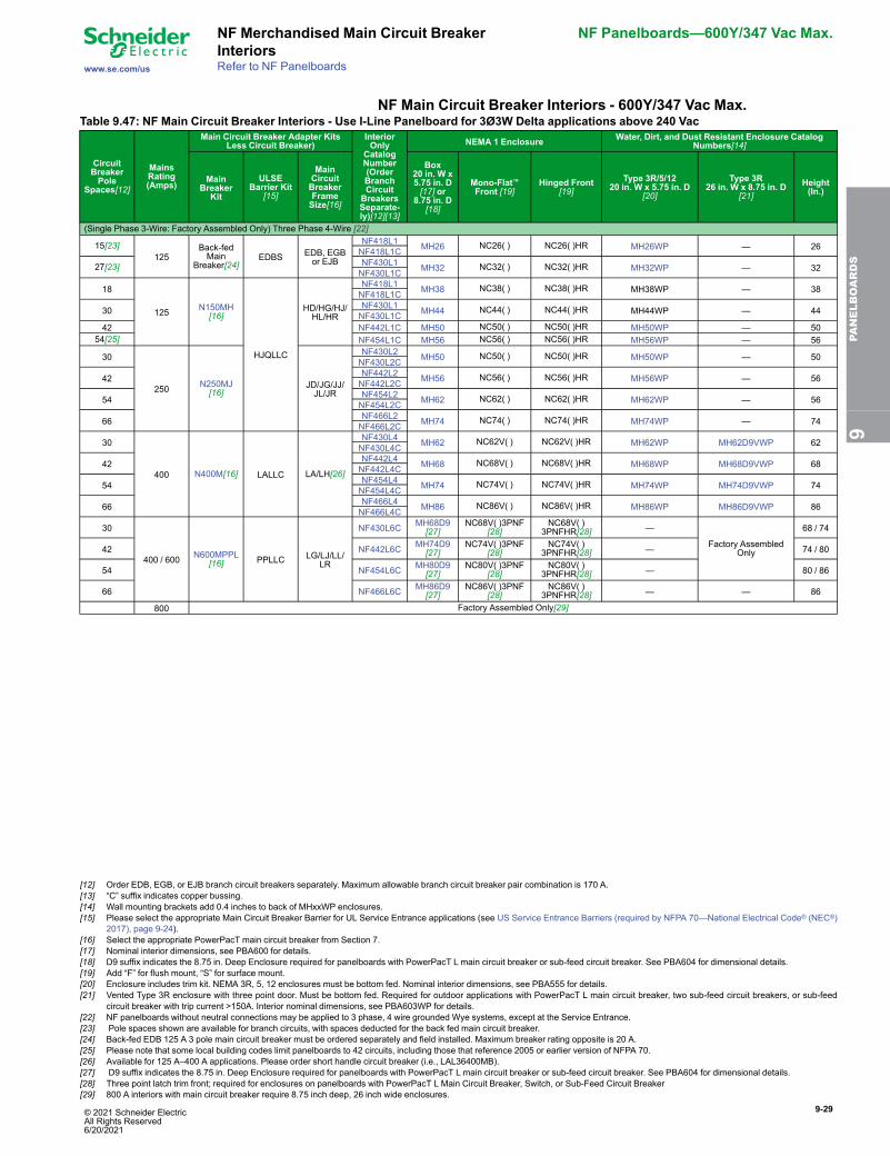
© 2021 Schneider Electric All Rights Reserved6/20/2021
9-29
www.se.com/us
NF Merchandised Main Circuit BreakerInteriors
NF Panelboards—600Y/347 Vac Max.
Refer to NF Panelboards
NF Main Circuit Breaker Interiors - 600Y/347 Vac Max.Table 9.47: NF Main Circuit Breaker Interiors - Use I-Line Panelboard for 3Ø3W Delta applications above 240 Vac
CircuitBreakerPole
Spaces[12]
MainsRating(Amps)
Main Circuit Breaker Adapter KitsLess Circuit Breaker)
InteriorOnly
CatalogNumber(OrderBranchCircuitBreakersSeparate-ly)[12][13]
NEMA 1 Enclosure Water, Dirt, and Dust Resistant Enclosure CatalogNumbers[14]
MainBreaker
Kit
ULSEBarrier Kit
[15]
MainCircuitBreakerFrameSize[16]
Box20 in. W x5.75 in. D[17] or
8.75 in. D[18]
Mono-Flat™Front [19]
Hinged Front[19]
Type 3R/5/1220 in. W x 5.75 in. D
[20]
Type 3R26 in. W x 8.75 in. D
[21]Height(In.)
(Single Phase 3-Wire: Factory Assembled Only) Three Phase 4-Wire [22]
15[23]125
Back-fedMain
Breaker[24]EDBS EDB, EGB
or EJB
NF418L1 MH26 NC26( ) NC26( )HR MH26WP — 26NF418L1C
27[23] NF430L1 MH32 NC32( ) NC32( )HR MH32WP — 32NF430L1C
18
125 N150MH[16]
HJQLLC
HD/HG/HJ/HL/HR
NF418L1 MH38 NC38( ) NC38( )HR MH38WP — 38NF418L1C
30 NF430L1 MH44 NC44( ) NC44( )HR MH44WP — 44NF430L1C42 NF442L1C MH50 NC50( ) NC50( )HR MH50WP — 50
54[25] NF454L1C MH56 NC56( ) NC56( )HR MH56WP — 56
30
250 N250MJ[16]
JD/JG/JJ/JL/JR
NF430L2 MH50 NC50( ) NC50( )HR MH50WP — 50NF430L2C
42 NF442L2 MH56 NC56( ) NC56( )HR MH56WP — 56NF442L2C
54 NF454L2 MH62 NC62( ) NC62( )HR MH62WP — 56NF454L2C
66 NF466L2 MH74 NC74( ) NC74( )HR MH74WP — 74NF466L2C
30
400 N400M[16] LALLC LA/LH[26]
NF430L4 MH62 NC62V( ) NC62V( )HR MH62WP MH62D9VWP 62NF430L4C
42 NF442L4 MH68 NC68V( ) NC68V( )HR MH68WP MH68D9VWP 68NF442L4C
54 NF454L4 MH74 NC74V( ) NC74V( )HR MH74WP MH74D9VWP 74NF454L4C
66 NF466L4 MH86 NC86V( ) NC86V( )HR MH86WP MH86D9VWP 86NF466L4C
30
400 / 600 N600MPPL[16] PPLLC LG/LJ/LL/
LR
NF430L6C MH68D9[27]
NC68V( )3PNF[28]
NC68V( )3PNFHR[28] —
Factory AssembledOnly
68 / 74
42 NF442L6C MH74D9[27]
NC74V( )3PNF[28]
NC74V( )3PNFHR[28] — 74 / 80
54 NF454L6C MH80D9[27]
NC80V( )3PNF[28]
NC80V( )3PNFHR[28] — 80 / 86
66 NF466L6C MH86D9[27]
NC86V( )3PNF[28]
NC86V( )3PNFHR[28] — — 86
800 Factory Assembled Only[29]
9PA
NELBOARDS
[12] Order EDB, EGB, or EJB branch circuit breakers separately. Maximum allowable branch circuit breaker pair combination is 170 A.[13] “C” suffix indicates copper bussing.[14] Wall mounting brackets add 0.4 inches to back of MHxxWP enclosures.[15] Please select the appropriate Main Circuit Breaker Barrier for UL Service Entrance applications (see US Service Entrance Barriers (required by NFPA 70—National Electrical Code® (NEC®)
2017), page 9-24).[16] Select the appropriate PowerPacT main circuit breaker from Section 7.[17] Nominal interior dimensions, see PBA600 for details.[18] D9 suffix indicates the 8.75 in. Deep Enclosure required for panelboards with PowerPacT L main circuit breaker or sub-feed circuit breaker. See PBA604 for dimensional details.[19] Add “F” for flush mount, “S” for surface mount.[20] Enclosure includes trim kit. NEMA 3R, 5, 12 enclosures must be bottom fed. Nominal interior dimensions, see PBA555 for details.[21] Vented Type 3R enclosure with three point door. Must be bottom fed. Required for outdoor applications with PowerPacT L main circuit breaker, two sub-feed circuit breakers, or sub-feed
circuit breaker with trip current >150A. Interior nominal dimensions, see PBA603WP for details.[22] NF panelboards without neutral connections may be applied to 3 phase, 4 wire grounded Wye systems, except at the Service Entrance.[23] Pole spaces shown are available for branch circuits, with spaces deducted for the back fed main circuit breaker.[24] Back-fed EDB 125 A 3 pole main circuit breaker must be ordered separately and field installed. Maximum breaker rating opposite is 20 A.[25] Please note that some local building codes limit panelboards to 42 circuits, including those that reference 2005 or earlier version of NFPA 70.[26] Available for 125 A–400 A applications. Please order short handle circuit breaker (i.e., LAL36400MB).[27] D9 suffix indicates the 8.75 in. Deep Enclosure required for panelboards with PowerPacT L main circuit breaker or sub-feed circuit breaker. See PBA604 for dimensional details.[28] Three point latch trim front; required for enclosures on panelboards with PowerPacT L Main Circuit Breaker, Switch, or Sub-Feed Circuit Breaker[29] 800 A interiors with main circuit breaker require 8.75 inch deep, 26 inch wide enclosures.
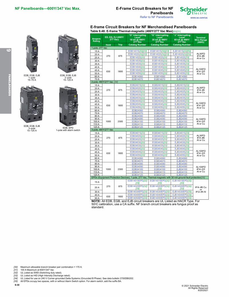
9-30 © 2021 Schneider Electric All Rights Reserved
6/20/2021
NF Panelboards—600Y/347 Vac Max. E-Frame Circuit Breakers for NFPanelboards
www.se.com/usRefer to NF Panelboards
E-frame Circuit Breakers for NF Merchandised Panelboards
EDB, EGB, EJB1–pole15–70 A
EDB, EGB, EJB2–pole
15–125 A
EDB, EGB, EJB3–pole
15–125 AEDB, EPD
1-pole with alarm switch
Table 9.48: E-frame Thermal-magnetic (480Y/277 Vac Max)[30][31]
AmpereRating
ED, EG, EJ (480Y/277 Vac)
“D” InterruptingLevel
18 kA @ 480Y/277 Vac
“G” InterruptingLevel
35 kA @ 480Y/277 Vac
“J” InterruptingLevel
65 kA @ 480Y/277 Vac
TerminalWire Range
(AWG)Hold Trip Catalog Number Catalog Number Catalog Number
1-pole, 277 Vac 15 A
270 875
EDB14015[32][33] EGB14015[32][33] EJB14015[32][33]AL30FD#14–#6Al or Cu
20 A EDB14020[32][33] EGB14020[32][33] EJB14020[32][33] 25 A EDB14025[33] EGB14025[33] EJB14025[33] 30 A EDB14030[33] EGB14030[33] EJB14030[33] 35 A
630 1800
EDB14035[33] EGB14035[33] EJB14035[33]
AL100FD#14–2/0Al or Cu
40 A EDB14040[33] EGB14040[33] EJB14040[33] 45 A EDB14045[33] EGB14045[33] EJB14045[33] 50 A EDB14050[33] EGB14050[33] EJB14050[33] 60 A EDB14060 EGB14060 EJB14060 70 A EDB14070 EGB14070 EJB14070
2-pole, 480Y/277 Vac [34] 15 A
270 875
EDB24015[33] EGB24015[33] EJB24015[33]AL30FD#14–#6Al or Cu
20 A EDB24020[33] EGB24020[33] EJB24020[33] 25 A EDB24025[33] EGB24025[33] EJB24025[33] 30 A EDB24030[33] EGB24030[33] EJB24030[33] 35 A
630 1800
EDB24035[33] EGB24035[33] EJB24035[33]
AL100FD#14–2/0Al or Cu
40 A EDB24040[33] EGB24040[33] EJB24040[33] 45 A EDB24045[33] EGB24045[33] EJB24045[33] 50 A EDB24050[33] EGB24050[33] EJB24050[33] 60 A EDB24060 EGB24060 EJB24060 70 A EDB24070 EGB24070 EJB24070 80 A
1000 2300
EDB24080 EGB24080 EJB24080AL100FD#14–2/0Al or Cu
90 A EDB24090 EGB24090 EJB24090100 A EDB24100 EGB24100 EJB24100110 A EDB24110 EGB24110 EJB24110125 A EDB24125 EGB24125 EJB24125
3-pole, 480Y/277 Vac 15 A
270 875
EDB34015[33] EGB34015[33] EJB34015[33]AL30FD#14–#6Al or Cu
20 A EDB34020[33] EGB34020[33] EJB34020[33] 25 A EDB34025[33] EGB34025[33] EJB34025[33] 30 A EDB34030[33] EGB34030[33] EJB34030[33] 35 A
630 1800
EDB34035[33] EGB34035[33] EJB34035[33]
AL100FD#14–2/0Al or Cu
40 A EDB34040[33] EGB34040[33] EJB34040[33] 45 A EDB34045[33] EGB34045[33] EJB34045[33] 50 A EDB34050[33] EGB34050[33] EJB34050[33] 60 A EDB34060 EGB34060 EJB34060 70 A EDB34070 EGB34070 EJB34070 80 A
1000 2300
EDB34080 EGB34080 EJB34080AL100FD#14–2/0Al or Cu
90 A EDB34090 EGB34090 EJB34090100 A EDB34100 EGB34100 EJB34100110 A EDB34110 EGB34110 EJB34110125 A EDB34125 EGB34125 EJB34125
EPDs (Equipment Protection Devices), 1-pole, 277 Vac, Thermal-magnetic with 30 mA ground-fault protection[35]
15 A
270 875
EDB14015EPD[32][33]
EGB14015EPD[32][33]
EJB14015EPD[32][33]
#14–#6 Cuor
#12–#4 Al
20 A EDB14020EPD[32][33]
EGB14020EPD[32][33]
EJB14020EPD[32][33]
30 A EDB14030EPD[33] EGB14030EPD[33] EJB14030EPD[33] 40 A
630 1800EDB14040EPD[33] EGB14040EPD[33] EJB14040EPD[33]
50 A EDB14050EPD[33] EGB14050EPD[33] EJB14050EPD[33]NOTE: All EDB, EGB, and EJB circuit breakers are UL Listed as HACR Type. For50oC calibration, use a CA suffix. NF branch circuit breakers are fungus proof asstandard.
9PA
NELBOARDS
[30] Maximum allowable branch breaker pair combination = 170 A.[31] 100 A Maximum at 600Y/347 Vac[32] UL Listed as SWD (Switching duty rated).[33] UL Listed as HID (High Intensity Discharge rated).[34] UL Listed for use on 240 V Corner-grounded Delta Systems (Grounded B Phase). See data bulletin 2700DB0202.[35] All EPDs occupy two spaces, with or without Alarm Switch option. For alarm switch, add the suffix BA.
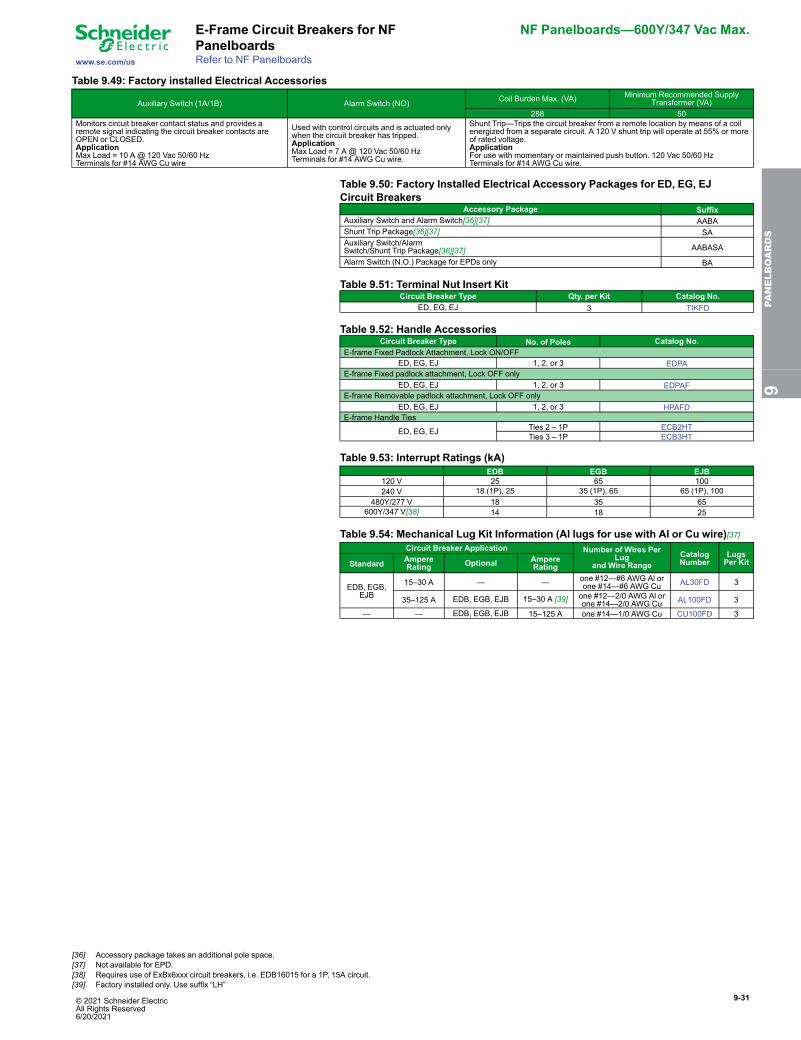
© 2021 Schneider Electric All Rights Reserved6/20/2021
9-31
www.se.com/us
E-Frame Circuit Breakers for NFPanelboards
NF Panelboards—600Y/347 Vac Max.
Refer to NF Panelboards
Table 9.49: Factory installed Electrical Accessories
Auxiliary Switch (1A/1B) Alarm Switch (NO) Coil Burden Max. (VA) Minimum Recommended SupplyTransformer (VA)
288 50Monitors circuit breaker contact status and provides aremote signal indicating the circuit breaker contacts areOPEN or CLOSED.ApplicationMax Load = 10 A @ 120 Vac 50/60 HzTerminals for #14 AWG Cu wire
Used with control circuits and is actuated onlywhen the circuit breaker has tripped.ApplicationMax Load = 7 A @ 120 Vac 50/60 HzTerminals for #14 AWG Cu wire.
Shunt Trip—Trips the circuit breaker from a remote location by means of a coilenergized from a separate circuit. A 120 V shunt trip will operate at 55% or moreof rated voltage.ApplicationFor use with momentary or maintained push button. 120 Vac 50/60 HzTerminals for #14 AWG Cu wire.
Table 9.50: Factory Installed Electrical Accessory Packages for ED, EG, EJCircuit Breakers
Accessory Package SuffixAuxiliary Switch and Alarm Switch[36][37] AABAShunt Trip Package[36][37] SAAuxiliary Switch/AlarmSwitch/Shunt Trip Package[36][37] AABASA
Alarm Switch (N.O.) Package for EPDs only BA
Table 9.51: Terminal Nut Insert KitCircuit Breaker Type Qty. per Kit Catalog No.
ED, EG, EJ 3 TIKFD
Table 9.52: Handle AccessoriesCircuit Breaker Type No. of Poles Catalog No.
E-frame Fixed Padlock Attachment, Lock ON/OFFED, EG, EJ 1, 2, or 3 EDPA
E-frame Fixed padlock attachment, Lock OFF onlyED, EG, EJ 1, 2, or 3 EDPAF
E-frame Removable padlock attachment, Lock OFF onlyED, EG, EJ 1, 2, or 3 HPAFD
E-frame Handle Ties
ED, EG, EJ Ties 2 – 1P ECB2HTTies 3 – 1P ECB3HT
Table 9.53: Interrupt Ratings (kA)EDB EGB EJB
120 V 25 65 100240 V 18 (1P), 25 35 (1P), 65 65 (1P), 100
480Y/277 V 18 35 65600Y/347 V[38] 14 18 25
Table 9.54: Mechanical Lug Kit Information (Al lugs for use with Al or Cu wire)[37]Circuit Breaker Application Number of Wires Per
Lugand Wire Range
CatalogNumber
LugsPer KitStandard Ampere
Rating Optional AmpereRating
EDB, EGB,EJB
15–30 A — — one #12—#6 AWG Al orone #14—#6 AWG Cu AL30FD 3
35–125 A EDB, EGB, EJB 15–30 A [39] one #12—2/0 AWG Al orone #14—2/0 AWG Cu AL100FD 3
— — EDB, EGB, EJB 15–125 A one #14—1/0 AWG Cu CU100FD 3
9PA
NELBOARDS
[36] Accessory package takes an additional pole space.[37] Not available for EPD.[38] Requires use of ExBx6xxx circuit breakers, i.e. EDB16015 for a 1P, 15A circuit.[39] Factory installed only. Use suffix “LH”
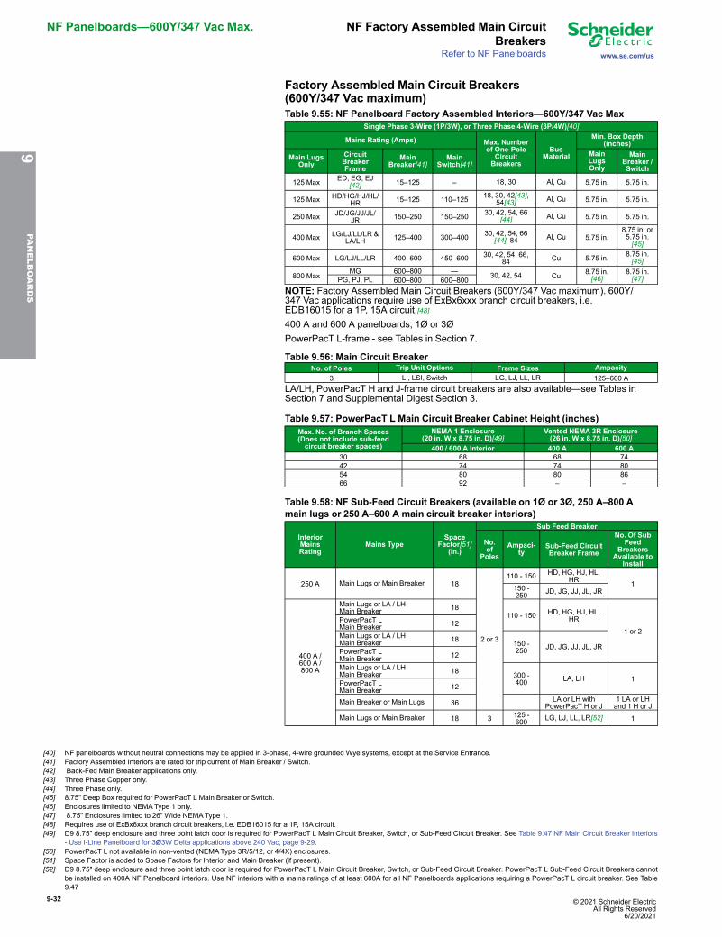
9-32 © 2021 Schneider Electric All Rights Reserved
6/20/2021
NF Panelboards—600Y/347 Vac Max. NF Factory Assembled Main CircuitBreakers
www.se.com/usRefer to NF Panelboards
Factory Assembled Main Circuit Breakers(600Y/347 Vac maximum)Table 9.55: NF Panelboard Factory Assembled Interiors—600Y/347 Vac Max
Single Phase 3-Wire (1P/3W), or Three Phase 4-Wire (3P/4W)[40]
Mains Rating (Amps) Max. Numberof One-Pole
CircuitBreakers
BusMaterial
Min. Box Depth(inches)
Main LugsOnly
CircuitBreakerFrame
MainBreaker[41]
MainSwitch[41]
MainLugsOnly
MainBreaker /Switch
125 Max ED, EG, EJ[42] 15–125 – 18, 30 Al, Cu 5.75 in. 5.75 in.
125 Max HD/HG/HJ/HL/HR 15–125 110–125 18, 30, 42[43],
54[43] Al, Cu 5.75 in. 5.75 in.
250 Max JD/JG/JJ/JL/JR 150–250 150–250 30, 42, 54, 66
[44] Al, Cu 5.75 in. 5.75 in.
400 Max LG/LJ/LL/LR &LA/LH 125–400 300–400 30, 42, 54, 66
[44], 84 Al, Cu 5.75 in.8.75 in. or5.75 in.[45]
600 Max LG/LJ/LL/LR 400–600 450–600 30, 42, 54, 66,84 Cu 5.75 in. 8.75 in.
[45]
800 MaxMG 600–800 — 30, 42, 54 Cu 8.75 in.
[46]8.75 in.[47]PG, PJ, PL 600–800 600–800
NOTE: Factory Assembled Main Circuit Breakers (600Y/347 Vac maximum). 600Y/347 Vac applications require use of ExBx6xxx branch circuit breakers, i.e.EDB16015 for a 1P, 15A circuit.[48]400 A and 600 A panelboards, 1Ø or 3ØPowerPacT L-frame - see Tables in Section 7.
Table 9.56: Main Circuit BreakerNo. of Poles Trip Unit Options Frame Sizes Ampacity
3 LI, LSI, Switch LG, LJ, LL, LR 125–600 ALA/LH, PowerPacT H and J-frame circuit breakers are also available—see Tables inSection 7 and Supplemental Digest Section 3.
Table 9.57: PowerPacT L Main Circuit Breaker Cabinet Height (inches)Max. No. of Branch Spaces(Does not include sub-feedcircuit breaker spaces)
NEMA 1 Enclosure(20 in. W x 8.75 in. D)[49]
Vented NEMA 3R Enclosure(26 in. W x 8.75 in. D)[50]
400 / 600 A Interior 400 A 600 A30 68 68 7442 74 74 8054 80 80 8666 92 – –
Table 9.58: NF Sub-Feed Circuit Breakers (available on 1Ø or 3Ø, 250 A–800 Amain lugs or 250 A–600 A main circuit breaker interiors)
InteriorMainsRating
Mains TypeSpace
Factor[51](in.)
Sub Feed Breaker
No.of
PolesAmpaci-
tySub-Feed CircuitBreaker Frame
No. Of SubFeed
BreakersAvailable to
Install
250 A Main Lugs or Main Breaker 18
2 or 3
110 - 150 HD, HG, HJ, HL,HR 1150 -
250 JD, JG, JJ, JL, JR
400 A /600 A /800 A
Main Lugs or LA / LHMain Breaker 18
110 - 150 HD, HG, HJ, HL,HR
1 or 2PowerPacT LMain Breaker 12
Main Lugs or LA / LHMain Breaker 18 150 -
250 JD, JG, JJ, JL, JRPowerPacT LMain Breaker 12
Main Lugs or LA / LHMain Breaker 18 300 -
400 LA, LH 1PowerPacT LMain Breaker 12
Main Breaker or Main Lugs 36 LA or LH withPowerPacT H or J
1 LA or LHand 1 H or J
Main Lugs or Main Breaker 18 3 125 -600 LG, LJ, LL, LR[52] 1
9PA
NELBOARDS
[40] NF panelboards without neutral connections may be applied in 3-phase, 4-wire grounded Wye systems, except at the Service Entrance.[41] Factory Assembled Interiors are rated for trip current of Main Breaker / Switch.[42] Back-Fed Main Breaker applications only.[43] Three Phase Copper only.[44] Three Phase only.[45] 8.75" Deep Box required for PowerPacT L Main Breaker or Switch.[46] Enclosures limited to NEMAType 1 only.[47] 8.75" Enclosures limited to 26" Wide NEMAType 1.[48] Requires use of ExBx6xxx branch circuit breakers, i.e. EDB16015 for a 1P, 15A circuit.[49] D9 8.75" deep enclosure and three point latch door is required for PowerPacT L Main Circuit Breaker, Switch, or Sub-Feed Circuit Breaker. See Table 9.47 NF Main Circuit Breaker Interiors
- Use I-Line Panelboard for 3Ø3W Delta applications above 240 Vac, page 9-29.[50] PowerPacT L not available in non-vented (NEMAType 3R/5/12, or 4/4X) enclosures.[51] Space Factor is added to Space Factors for Interior and Main Breaker (if present).[52] D9 8.75" deep enclosure and three point latch door is required for PowerPacT L Main Circuit Breaker, Switch, or Sub-Feed Circuit Breaker. PowerPacT L Sub-Feed Circuit Breakers cannot
be installed on 400A NF Panelboard interiors. Use NF interiors with a mains ratings of at least 600A for all NF Panelboards applications requiring a PowerPacT L circuit breaker. See Table9.47
© 2021 Schneider Electric All Rights Reserved6/20/2021
9-33
www.se.com/us
NF Factory Assembled PanelboardCommon Features
NF Panelboards—600Y/347 Vac Max.
Refer to NF Panelboards
Common FeaturesTable 9.59: Sub-feed (Double) Lugs (Standard Copper Mechanical Lugs)
Mains Rating Sub-feed Lug Wire Range125 A two #6–2/0 AWG Al or Cu250 A two 1/0 AWG–350 kcmil or one 1/0 AWG-750 kcmil Al or Cu400 A two 1/0 AWG–750 kcmil Cu600 A (4) 4/0 AWG–500 kcmil Al or Cu800 A (6) 3/0 AWG–500 kcmil Al or Cu
Sub-feed (Double) Lugs (Standard Aluminum Mechanical Lugs): An additional mains and termination point that canbe used to feed out to another panelboard or device from the incoming service lines.Available on main lug interiors only.
Table 9.60: Sub-feed Lug Cabinet Data (Standard Aluminum Mechanical Lugs)Max. No. of
Branch SpacesMain Lugs Enclosure Height in Inches
125 A 250 A 400 A 600 A 800 A [53]18 26 — — — —30 32 38 50 74 8042 — 44 56 80 8654 — 50 62 86 92
Table 9.61: Feed-through Lugs (Standard Aluminum Mechanical Lugs)Mains Rating Feed-through Wire Range Wire
125 A one #6 AWG–2/0 kcmil Al or Cu250 A one #6 AWG–350 kcmil Al or Cu
400 A one 1/0 AWG–750 kcmil ortwo 1/0 AWG–350 kcmil Al or Cu
600 A two 1/0 AWG–750 kcmil Al or CuFeed-through Lugs (Standard Aluminum Mechanical Lugs): A second set of lugs assembled at the opposite endfrom the mains of the panelboard. Often used to connect another panelboard or device to the incoming lines.Available on main lugs and main circuit breaker panelboards.
Table 9.62: Feed-through Lugs Cabinet Data (Standard AluminumMechanical Lugs)Max.No.of
Bran-chSpa-ces
Enclosure Height in Inches125 A 100/125 A 250 A 400 A LA/LH 600 A 800 AMain
Breaker(back-fedonly)
MainLugs
MainBreaker
MainLugs
MainBreaker
MainLugs
MainBreaker
MainLugs
MainBreaker[54]
MainLugs[53]
18 38 32 44 — — — — — — —30 44 38 50 50 62 56 68 56 74 5642 — — — 56 68 62 74 62 80 6254 — — — 62 74 68 80 68 86 68
Table 9.63: NF Equipment Ground Bar Kits [55]
Interior Rating Circuit Count Aluminum Copper Ground BarInsulator Kit
125 A / 250 A18 PK12GTA
PK27GTACU PKGTAB30 PK18GTA
42, 54 PK23GTA250 A 66 and Split Bus PK27GTA
400 A / 600 A All PK27GTA
Table 9.64: Name PlatesName Plates
Standard white face/black letter laminated bakelite, 1 in. x 3.5 in., adhesive-backed or screw mountable with screwsin a bag assembly
Table 9.65: NF Panelboard Neutral Assembly Options
InteriorRating
Without Sub-Feed or Thru-Feed Lugs With Sub-Feed or Thru-Feed Lugs100% Neutrals 200% Neutrals[56] 100% Neutrals 200% Neutrals[56]
Alumi-num Copper Alumi-
num Copper Alumi-num Copper Alumi-
num Copper
125A
Standard
NFN1CU NFNL1 FA Only[57] Std NFN1CU NFNL1 FA Only
[57]
250A NFN2CU NFNL2 FA Only[57] Std NFN2CU NFNL2 FA Only
[57]
400ANFN6CU
NFNL4 FA Only[57] Std NFN6CU FA Only
[57]FA Only[57]
600A FA Only[57]
FA Only[57]
FA Only[57]
FA Only[57]
FA Only[57]
FA Only[57]
800A FA Only[57]
FA Only[57]
FA Only[57]
FA Only[57]
FA Only[57]
FA Only[57]
FA Only[57]
FA Only[57]
9PA
NELBOARDS
[53] 800 A main lug panelboards require an 8.75 in. deep and 26 in. wide box.[54] 600 A main circuit breaker panelboards require an 8.75 in. deep, 26 in. wide box.[55] One (1) PK kit supplied when ground bar is specified. Two (2) PK kits supplied when "extra" ground bar is ordered.[56] 200% Neutrals not available on Column Width interiors[57] FA - Factory Assembled Panelboards
9-34 © 2021 Schneider Electric All Rights Reserved
6/20/2021
NF Panelboards—600Y/347 Vac Max. NF Factory Assembled PanelboardCommon Features
www.se.com/usRefer to NF Panelboards
Table 9.66: NF Main Neutral Conductors—(Quantity) and Wire Size
Interior RatingMechanical Neutral Line Lugs Compression Neutral Line Lugs
Standard Oversized StandardNeutral Lug Wire Range Actual Lug Wire Range Actual Lug Wire Range
125 A (1) 2/0 AWG Cu or Al (1) #6 AWG-350 kcmil (1) #6-1/0 AWG Cu or(1) #4-300 kcmil Al
250 A (1) 250 kcmil Cuor (1) 350 kcmil Al
(2) 1/0 AWG-300 kcmilor (1) 1/0 AWG-750 kcmil
(1) 2/0 AWG-300 kcmil Cuor (1) 250-350 kcmil Al
400 A(2) 1/0 AWG 300 kcmilor (1) 700 kcmil Cu or Al
— (1) 400-750 kcmil Cuor (1) 2/0 AWG-500 kcmil Al
600 A(2) 1/0 AWG-750 kcmil Cu or Al[58]
(1) 2/0 AWG-500 kcmil Cuor Al(3) 4/0 AWG-500 kcmil Cu or Al[59]
800 A —NOTE: 200% applications require gutter mounted neutral in special (W x 26 in.) enclosure factory assembled only. One exception, withoutsubfeed lugs, feed-thru lugs and subfeed breakers 400 A (30-84 circuit interiors) and 600 A (30-54 circuit interiors) does not require anspecial enclosure.Neutral conductors must be of size and quantity per table above.
Table 9.67: Metal Directory FrameMetal Directory Frame
Metal Directory Frames are available as a premium factory assembled alternative to standard plastic directory cardholders on the back of panelboard trim fronts.
Table 9.68: Hinged Door-in-Door TrimHinged Door-in-Door Trim
Hinged Door-in-Door Trim has piano hinge down one side.Inner door has a lock, outer door is retained with screwsHinged Door-in-Door with Outer Door Lock in place of screws
Table 9.69: Weatherproof or Dusttight Cabinets NEMAType 3R, 4, 4X, 5, 12)Weather resistant and Dust resistant Cabinets —Type 3R, 4, 4X, 5, 12
NEMAType 4, 4X, 4, 12 enclosures not available with panelboards having PowerPacT L circuit breakers
Table 9.70: Optional Factory Assembled Lugs for Main Lug Only and Main CircuitBreaker Interiors
Incoming Lugs TypeAluminum Compression LugsCopper Mechanical LugsCopper Compression Lugs
Table 9.71: Surgelogic™ Hard Bus SPD—Model[60]Surge CurrentRating kA
100120160200240
Table 9.72: Surgelogic SPD OptionsSurgelogic SPD Options
Surge CounterDry ContactsRemote MonitorNOTE: For additional factory modifications, see Modifications For FactoryAssembled Panelboards, page 9-66.
Table 9.73: NQ and NF Lighting Contactors—Mechanically Held(Furnish a one-line power and control voltage connection diagram.)
ASCO 920 SeriesAmpacity 2-Pole 3-Pole
30 Y Y60 Y Y75 Y Y100 Y Y150 Y Y225 Y Y
NOTE: Lighting Contactors increase box & trim length by 18 in. (457 mm)
9PA
NELBOARDS
[58] Factory Assembled only; increases enclosure length 6"-12".[59] Factory Assembled only; enclosure length increases 6-12"; requires 8.75" deep D9 enclosure.[60] Panelboard box height with SPD unit—Contact your local Schneider Electric representative or distributor.
© 2021 Schneider Electric All Rights Reserved6/20/2021
9-35
www.se.com/us
NF Panelboard Accessories NF Panelboards—600Y/347 Vac Max.Accessories
NF Merchandised and Factory Assembled AccessoriesTable 9.74: NF Merchandised Interiors with Surge Protection Devices (SPD)
AvailablePole
SpacesMain Rating
Main CircuitBreaker
Adapter KitMain Circuit
Breaker FrameInterior Only
Catalog No. [61]Surge Current
RatingNEMA 1 Enclosure NEMA 3R, 5,
12 EnclosureBox Mono-Flat Front Hinged Front
42250 A
Main Lug OnlyNF442L2TVS416C
160 kA
MH56 NC56( ) NC56( )HR MHWP56N250MJ [62] JD/JG/JJ/JL MH68 NC68( ) NC68( )HR MHWP68
400 AMain Lug Only
NF442L4TVS416CMH68 NC68V( ) NC68V( )HR MHWP68
N400M[63] LA/LH MH80 NC80V( ) NC80V( )HR MHWP80
AccessoriesTable 9.75: NF Merchandised Neutrals
MainsAmpacity
200% Neutral Kit Copper 100% Neutral KitCatalog No. Catalog No.
125 NFNL1 NFN1CU250 NFNL2 NFN2CU400 NFNL4[64] NFN6CU600 Factory Assembled Only NFN6CU[64]
Table 9.76: NF Merchandised Interior Modification KitsMains
Ampacity
Sub-feed Lugs [65] Feed-through Lugs [65]Mains
Ampacity
Sub-feed Circuit Breaker Kits [65] (circuit breaker not Included)
Catalog No. Catalog No.Single Sub-feed Circuit Breaker Twin Sub-feed Circuit Breakers
Catalog No. Catalog No.125 NF125SFL NF125FTL 250 NF250SFBH/NF250SFBJ —250 NF250SFL NF250FTL
400N600MPPL
NF600SFBH400 NF400SFL [66] NF400FTL NF600SFBJ600 Factory Assembled Only 600 Factory Assembled Only800 800 Factory Assembled Only
NOTE: NF250SFBH and NF600SFBH are for use with HDL, HGL, HJL, HLL, and HRL circuit breakers. NF250SFBJ and NF600SFBJ are foruse with JDL, JGL, JJL, JLL, and JRL circuit breakers.
Table 9.77: NF Special Features Standard NEMAType 1 Enclosure Selection Table—Enclosure Catalog Number for Standard MainMechanical Lugs Only
FeatureMain Lugs Only
Sub-feed Lugs Feed-through Lugs Sub-feed Circuit Breaker
Interior Rating 125 A 250 A 400 A 600 A 800 A 125 A 250 A 400 A 600 A 800 A 250 A 400 A 400 A[67] 600 A 600 A
[67] 800 A
No. of Circuits NEMA 1 Enclosure Catalog Number NEMA 1 Enclosure Catalog Number NEMA 1 Enclosure Catalog Number18 MH26 — — — — MH32 — — — — — — — — —
FactoryAssembled
Only
30 MH32 MH38 MH50Factory
AssembledOnly
MH38 MH50 MH56Factory
AssembledOnly
MH56 MH68 MH62D9 MH68 MH62D942 — MH44 MH56 — MH56 MH62 MH62 MH74 MH68D9 MH74 MH68D954 — MH50 MH62 — MH62 MH68 MH68 MH80 MH74D9 MH86 MH74D966 — MH62 MH74 — MH74 MH80 MH80 MH92 — MH92 —84 — — MH86 — — — — — — — —
Table 9.78: Special Features Enclosures Selection Table—Merchandised NF Vertically Mounted Main Breaker Panelboards withAccessories (by Mains Rating)
No. of Circuits
Vertical Main Circuit Breaker (MB) [68] Back-fed MBSub-feed Circuit Breaker (PowerPacT H or J) Feed-through Lugs (FTL) FTL
125 A 250 A 400 A 600 A 800 A 125 A 250 A 400 A[68] 600 A 125 ACat. No. Cat. No. Cat. No. Cat. No. Cat. No. Cat. No. Cat. No. Cat. No. Cat. No. Cat. No.
18 — — — — — MH44 — — — MH3230 — MH68 MH80
FactoryAssembled
Only
FactoryAssembled
Only
MH50 MH62 MH68Factory
AssembledOnly
MH3842 — MH74 MH86 — MH68 MH74 —54 — MH80 MH92 — MH74 MH86 —66 — MH92 — — — MH86 MH92 —
Table 9.79: Optional Main Lug Kits for Main Lug Panelboards
AmpacityAl Compression Lug Kit Cu Mechanical Lug Kit Cu Compression Lug Kit [66]
Catalog No. Lug Wire Range Catalog No. Lug Wire Range Catalog No. Lug Wire Range125 NFALV1 [69] one #4 AWG–300 kcmil NFCUM1 #6–2/0 AWG NFCUV1 [70] one #6–1/0 AWG250 NFALV2 one 250–350 kcmil NFCUM2 #6 AWG–250 kcmil NFCUV2 [70] one 2/0 AWG–300 kcmil
400 NFALV4 two 2/0 AWG–500 kcmil NFCUM4 one 1/0 AWG–750 kcmil, ortwo 1/0 AWG–350 kcmil NFCUV4 one 400–750 kcmil
600 NFALV6 two 2/0 AWG–500 kcmil NFCUM6 two 1/0 AWG–750 kcmil NFCUV6 two 250–500 kcmil800 Contact your local Schneider Electric representative or distributor.
9PA
NELBOARDS
[61] Order branch circuit breakers separately.[62] Select the appropriate PowerPacT main circuit breaker from Section 7.[63] Select an appropriate LA or LH Thermal-Magnetic Circuit Breaker from Section 7.[64] Not to be used with SFL, FTL, or SFB. These combinations are factory assembled only.[65] Available factory assembled only on non-linear panelboards.[66] Use copper wire only.[67] PowerPacT LG, LJ, LL, or LR Sub-Feed Circuit Breaker.[68] 400 A dimension for LA/LH main circuit breakers only.[69] Use of this kit requires an additional 6 in. added to box height.[70] Use of this kit to terminate larger than standard wire size requires an additional 6 in. added to box height.
9-36 © 2021 Schneider Electric All Rights Reserved
6/20/2021
Separated Distribution and Split BusPanelboards
Separated Distribution and Split Bus NFand NQ Panelboards
www.se.com/usRefer to Panelboards
Table 9.80: NFAccessoriesDescription Catalog No. Description Catalog No.
Aluminum Equipment Ground Bar PK27GTA Replacement Part KitsCopper Equipment Ground Bar PK27GTACU NF 125A AL Replacement Compression Lug Kit (300 MCM) NFRPLAV1
AWG #1-4/0 Aluminum Lug on Aluminum Equipment Ground Bar PK23GTAL 600 A NF Main Breaker PowerPacT L Deadfront (NEMA 3R) Replacement Kit NFRPLMB63-RPPL
Equipment Ground Bar Insulator Kit PKGTAB Filler plate (15 per package) NFFP15
Circuit I.D. number strips E-frame Fixed padlock attachment, Lock ON/OFFfor ED, EG, and EJ Circuit Breakers 1, 2, or 3 poles EDPA
102 odd/even (left side numbered 1, 3, 5...101) NF102OE E-frame Fixed padlock attachment, Lock OFF onlyfor ED, EG, and EJ Circuit Breakers 1, 2, or 3 poles EDPAF
103–204 odd/even (left side numbered 103, 105, 107...203) NF204OE Drip Hood for 20 in. wide enclosures MHT2DH201–102 sequential (left side numbered 1, 2, 3 ...102) NF102S103–204 sequential (left side numbered 103, 104, 105... 204) NF204SRail and Deadfront Extensions6 in. Extension NF6RDE12 in. Extension NF12RDE18 in. Extension NF18RDE24 in. Extension NF24RDE
Table 9.81: Add-On Lugs for Neutral Bars or Ground Bars[71]Catalog Number Lug Wire Range (AWG) Wire AmpereQO70AN #12 to #2 Al or #14 to #4 Cu 70 AQ1100AN #14 to #1/0 Al or Cu 80 - 100 A
Separated Distribution and Split Bus NF and NQ Panelboards
Square D Separated Distribution and Split Bus Panelboards providecompact, affordable options to protect lighting, HVAC, renewableenergy, and appliance circuits in buildings.Separated Distribution Panelboards facilitate Separation of ElectricalCircuits for Electrical Energy Monitoring to simplify compliance withSection 130.5-B of California’s 2016 Building Energy EfficiencyStandards.NOTE: Refer to Data Bulletin 1600HO1701 for more information.
Special lug pad adaptors allow field removal of cables, for easy fieldinstallation of solid core or split CTs for electrical energy measurement,by load type.
Split Bus panelboards enable configurations of two or three back fedmain circuit breakers, with independent branch distribution sections, ina single enclosure.
9PA
NELBOARDS
[71] Requires two standard termination spaces on Neutral or Ground bar.
© 2021 Schneider Electric All Rights Reserved6/20/2021
9-37
www.se.com/us
Separated Distribution and Split Bus NFand NQ Panelboards
Separated Distribution and Split BusPanelboards
Refer to Panelboards
Table 9.82: Separated Distribution Interiors(Cabled Between Sections)
Separated DistributionInteriors
(cabled between sections)
Max. No. ofAvailable Pole
SpacesBox Height
(in.)
Prod-uct
Family
MainAmp-acityMLO
VoltagePhases Main Split Split
2MainLugOnly
MainCir-cuitBrea-ker
NQ225 A
3 Ph
30 18 18 62 7418 18 18 62 74
400 A 30 18 18 80 9218 18 18 80 92
NF 250 A 3 Ph 30 18 18 80 9218 18 18 74 86
Table 9.83: Bus Bar Interiors(125 A Max. Split Amps)
Split Bus Bar Interiors(125 A Max. Split Amps)
Max. No. ofAvailable Pole
SpacesBox Height
(in.)
Prod-uct
Family
MainAmp-acityMLO
VoltagePhases Main Split Split
2MainLugOnly
MainCir-cuitBre-aker
NQ 225 A
1, 3 Ph 18 30 — 44 561, 3 Ph 30 18 — 44 561, 3 Ph 30 30 — 44 563 Ph 30 18 18 50 62
NF 250 A
3 Ph 18 30 — 56 681, 3 Ph 30 18 — 56 681, 3 Ph 30 30 — 62 743 Ph 30 18 18 74 86
Square D NF and NQ Separated Distribution and Split Bus Panelboards come FactoryAssembled with copper bus, with or without an integral Main Circuit Breaker. A widevariety of configurations may be submitted for quotation via Square D QuoteFAST, andmay be quoted or ordered by Authorized Distributors using SE Advantage or E-WayQuote Management.
Features:• Multiple branch section configurations (pole spaces per section):– Split Bus: 18-30; 30-18; 30-30; 30-18-18– Separated Distribution: 30-18-18; 18-18-18
• Up to 400 A Mains rating for NQ; up to 250 A Mains in NF panelboardsNotes:Enclosure width / depth: 20” / 5.75” minimum.Subfeed breaker or lugs, feed through lugs not available at top or bottom ends of panel.• Split Bus - feeder breaker (125 A max.) in downstream split section back-fed fromfeeder breaker in upstream main or split section.
• Segregated Distribution - cables may be removed in the field. Downstream Splitsection may have same rating as Main.
9PA
NELBOARDS
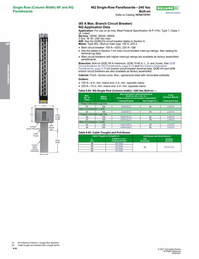
9-38 © 2021 Schneider Electric All Rights Reserved
6/20/2021
Single Row (Column Width) NF and NQPanelboards
NQ Single-Row Panelboards—240 VacBolt-on www.se.com/us
Refer to Catalog 1670CT0701
(60 A Max. Branch Circuit Breaker)NQ Application Data
8 in.5⁄8
20 in.
15 in.
PanelHeight
SolidNeutral
Bar
Pull Box(Cover Removed)
CableTrough
ColumnWidth
LightingPanelboard
CableTroughLength
Application: For use on ac only. Meet Federal Specification W-P-115c, Type 1, Class 1.UL Listed.Service: 1Ø3W, 3Ø3W, 3Ø4W,3 Grd. “B” Ø—240 Vac max.AIR: See the QOB(VH) circuit breaker tables in Section 9.Mains: Type NQ—Bolt-on main lugs: 100 A, 225 A• Main circuit breaker: 100 A—QOU, 225 A—QB• See the tables in Section 7 for main circuit breaker interrupt ratings. See catalog forterminal lug data.
• Main circuit breakers with higher interrupt ratings are available as factory assembledpanelboards.
Branches: Bolt-on QOB, 60 A maximum. QOB 10-60 A 1-, 2- and 3-pole. See QOBCircuit Breakers for NQ Panelboards, page 9-15 and NQ Factory AssembledPanelboards, page 9-18 for branch circuit breaker terminal data. QOB-VH and QHBbranch circuit breakers are also available as factory assembled.Cabinet: Front—Screw cover. Box—galvanized steel with removable endwalls.Gutters:• 100 A—4 in. min. mains end, 3 in. min. opposite mains• 225 A—10 in. min. mains end, 5 in. min. opposite mains
Table 9.84: NQ Single-Row (Column-width)—240 Vac Bolt-on [1]
Max.No. ofPoles
MainsRating
Box and Interior with Solid Neutral(8.625 in. W. x 5 in. D.)
(Order branch circuit breakers separately)Front
(Surface Mount)
Catalog Number Box Height (In.) Catalog Number1 Phase 3-Wire Main Lugs Only
30 225 NQ830L2C 45 LX45TSMain Circuit Breaker—2-pole
20 100 NQ820B1C 40 LX40TS3 Phase 4-Wire Main Lugs Only
30 100 NQ8430L1C 40 LX40TS42 225 NQ8442L2C 58 LX58TS
Main Circuit Breaker—3-pole30 100 NQ8430B1C 45 LX45TS42 225 NQ8442B2C 62 LX62TS
Table 9.85: Cable Troughs and Pull BoxesCable Troughs (L=Length) [2] Pull Boxes with Solid NeutralL
(In.)8.625 in. x 5 in.Catalog Number
S/NTerminals
CatalogNumber
36 MTX836
42 MPX8154248 MTX84856 MTX85666 MTX866
9PA
NELBOARDS
[1] 60 A Maximum Branch—Copper Bus Standard.[2] Cable troughs are standard with a trough barrier.
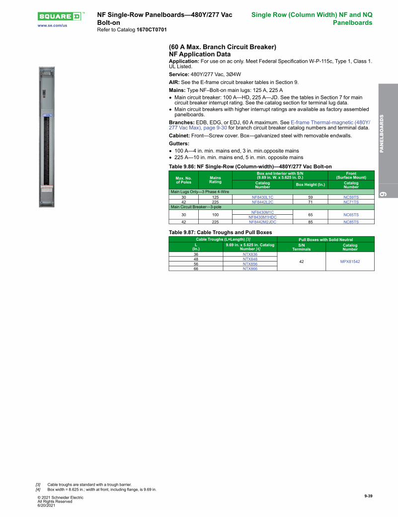
© 2021 Schneider Electric All Rights Reserved6/20/2021
9-39
www.se.com/us
NF Single-Row Panelboards—480Y/277 VacBolt-on
Single Row (Column Width) NF and NQPanelboards
Refer to Catalog 1670CT0701
(60 A Max. Branch Circuit Breaker)NF Application DataApplication: For use on ac only. Meet Federal Specification W-P-115c, Type 1, Class 1.UL Listed.Service: 480Y/277 Vac, 3Ø4WAIR: See the E-frame circuit breaker tables in Section 9.Mains: Type NF–Bolt-on main lugs: 125 A, 225 A• Main circuit breaker: 100 A—HD, 225 A—JD. See the tables in Section 7 for maincircuit breaker interrupt rating. See the catalog section for terminal lug data.
• Main circuit breakers with higher interrupt ratings are available as factory assembledpanelboards.
Branches: EDB, EDG, or EDJ, 60 A maximum. See E-frame Thermal-magnetic (480Y/277 Vac Max), page 9-30 for branch circuit breaker catalog numbers and terminal data.Cabinet: Front—Screw cover. Box—galvanized steel with removable endwalls.Gutters:• 100 A—4 in. min. mains end, 3 in. min.opposite mains• 225 A—10 in. min. mains end, 5 in. min. opposite mains
Table 9.86: NF Single-Row (Column-width)—480Y/277 Vac Bolt-on
Max. No.of Poles
MainsRating
Box and Interior with S/N(9.69 in. W. x 5.625 in. D.)
Front(Surface Mount)
CatalogNumber Box Height (In.) Catalog
NumberMain Lugs Only—3 Phase 4-Wire
30 125 NF8430L1C 59 NC59TS42 225 NF8442L2C 71 NC71TS
Main Circuit Breaker—3-pole
30 100 NF8430M1C 65 NC65TSNF8430M1HDC42 225 NF8442M2JDC 85 NC85TS
Table 9.87: Cable Troughs and Pull BoxesCable Troughs (L=Length) [3] Pull Boxes with Solid NeutralL
(In.)9.69 in. x 5.625 in. Catalog
Number [4]S/N
TerminalsCatalogNumber
36 NTX836
42 MPX8154248 NTX84856 NTX85666 NTX866
9PA
NELBOARDS
[3] Cable troughs are standard with a trough barrier.[4] Box width = 8.625 in.; width at front, including flange, is 9.69 in.
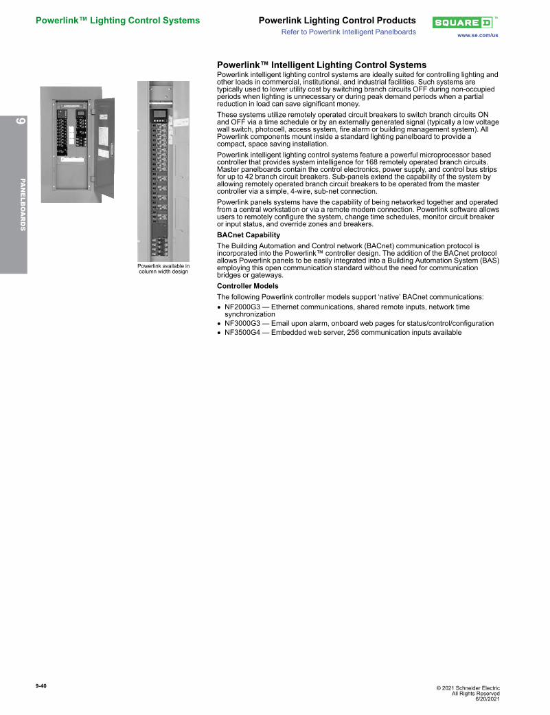
9-40 © 2021 Schneider Electric All Rights Reserved
6/20/2021
Powerlink™ Lighting Control Systems Powerlink Lighting Control Productswww.se.com/usRefer to Powerlink Intelligent Panelboards
Powerlink™ Intelligent Lighting Control Systems
Powerlink available incolumn width design
Powerlink intelligent lighting control systems are ideally suited for controlling lighting andother loads in commercial, institutional, and industrial facilities. Such systems aretypically used to lower utility cost by switching branch circuits OFF during non-occupiedperiods when lighting is unnecessary or during peak demand periods when a partialreduction in load can save significant money.These systems utilize remotely operated circuit breakers to switch branch circuits ONand OFF via a time schedule or by an externally generated signal (typically a low voltagewall switch, photocell, access system, fire alarm or building management system). AllPowerlink components mount inside a standard lighting panelboard to provide acompact, space saving installation.Powerlink intelligent lighting control systems feature a powerful microprocessor basedcontroller that provides system intelligence for 168 remotely operated branch circuits.Master panelboards contain the control electronics, power supply, and control bus stripsfor up to 42 branch circuit breakers. Sub-panels extend the capability of the system byallowing remotely operated branch circuit breakers to be operated from the mastercontroller via a simple, 4-wire, sub-net connection.Powerlink panels systems have the capability of being networked together and operatedfrom a central workstation or via a remote modem connection. Powerlink software allowsusers to remotely configure the system, change time schedules, monitor circuit breakeror input status, and override zones and breakers.BACnet CapabilityThe Building Automation and Control network (BACnet) communication protocol isincorporated into the Powerlink™ controller design. The addition of the BACnet protocolallows Powerlink panels to be easily integrated into a Building Automation System (BAS)employing this open communication standard without the need for communicationbridges or gateways.Controller ModelsThe following Powerlink controller models support ‘native’ BACnet communications:• NF2000G3 — Ethernet communications, shared remote inputs, network timesynchronization
• NF3000G3 — Email upon alarm, onboard web pages for status/control/configuration• NF3500G4 — Embedded web server, 256 communication inputs available
9PA
NELBOARDS
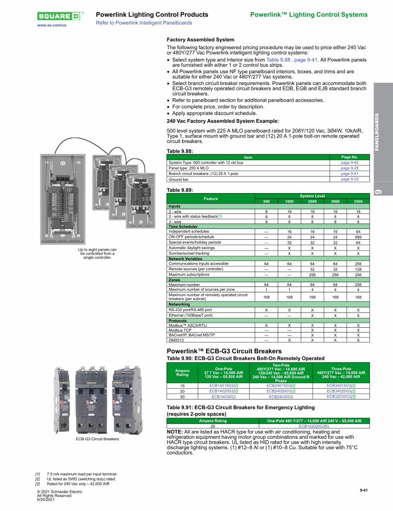
© 2021 Schneider Electric All Rights Reserved6/20/2021
9-41
www.se.com/us
Powerlink Lighting Control Products Powerlink™ Lighting Control SystemsRefer to Powerlink Intelligent Panelboards
Factory Assembled SystemThe following factory engineered pricing procedure may be used to price either 240 Vacor 480Y/277 Vac Powerlink intelligent lighting control systems:• Select system type and interior size from Table 9.88 , page 9-41. All Powerlink panelsare furnished with either 1 or 2 control bus strips.
• All Powerlink panels use NF type panelboard interiors, boxes, and trims and aresuitable for either 240 Vac or 480Y/277 Vac systems.
• Select branch circuit breaker requirements. Powerlink panels can accommodate bothECB-G3 remotely operated circuit breakers and EDB, EGB and EJB standard branchcircuit breakers.
• Refer to panelboard section for additional panelboard accessories.• For complete price, order by description.• Apply appropriate discount schedule.240 Vac Factory Assembled System Example:
Up to eight panels canbe controlled from asingle controller.
500 level system with 225 A MLO panelboard rated for 208Y/120 Vac, 3Ø4W, 10kAIR,Type 1, surface mount with ground bar and (12) 20 A 1-pole bolt-on remote operatedcircuit breakers.
Table 9.88:Item Page No.
System Type: 500 controller with 12 ckt bus page 9-42Panel type: 250 A MLO page 9-28Branch circuit breakers: (12) 20 A 1-pole page 9-41Ground bar page 9-33
Table 9.89:Feature
System Level500 1000 2000 3000 3500
Inputs2 - wire 8 16 16 16 162 - wire with status feedback[1] 8 8 8 8 83 - wire 8 8 8 8 8Time SchedulerIndependent schedules — 16 16 16 64ON-OFF periods/schedule — 24 24 24 999Special events/holiday periods — 32 32 32 64Automatic daylight savings — X X X XSunrise/sunset tracking — X X X XNetwork VariablesCommunications inputs accessible 64 64 64 64 256Remote sources (per controller) — — 32 32 128Maximum subscriptions — — 256 256 256ZonesMaximum number 64 64 64 64 256Maximum number of sources per zone 1 1 4 4 4Maximum number of remotely operated circuitbreakers (per subnet) 168 168 168 168 168
NetworkingRS-232 port/RS-485 port X X X X XEthernet (100BaseT port) — — X X XProtocolsModbus™ ASCII/RTU X X X X XModbus TCP — — X X XBACnet/IP, BACnet MS/TP — — X X XDMX512 — X X X X
Powerlink™ ECB-G3 Circuit Breakers
ECB-G3 Circuit Breakers
Table 9.90: ECB-G3 Circuit Breakers Bolt-On Remotely Operated
AmpereRating
One-Pole27 7 Vac – 14,000 AIR120 Vac – 65,000 AIR
Two-Pole480Y/277 Vac – 14,000 AIR120/240 Vac – 65,000 AIR
240 Vac – 14,000 AIR Ground BPhase
Three-Pole480Y/277 Vac – 14,000 AIR
240 Vac – 42,000 AIR
15 ECB14015G3[2] ECB24015G3[2] ECB34015G3[2]20 ECB14020G3[2] ECB24020G3[2] ECB34020G3[2]30 ECB14030G3 ECB24030G3 ECB32030G3[3]
Table 9.91: ECB-G3 Circuit Breakers for Emergency Lighting(requires 2-pole spaces)
Ampere Rating One-Pole 480 Y/277 – 14,000 AIR 240 V – 65,000 AIR20 ECB142020G3EL
NOTE: All are listed as HACR type for use with air conditioning, heating andrefrigeration equipment having motor group combinations and marked for use withHACR type circuit breakers. UL listed as HID rated for use with high intensitydischarge lighting systems. (1) #12–8 Al or (1) #10–8 Cu. Suitable for use with 75°Cconductors.
9PA
NELBOARDS
[1] 7.5 mA maximum load per input terminal.[2] UL listed as SWD (switching duty) rated.[3] Rated for 240 Vac only – 42,000 AIR
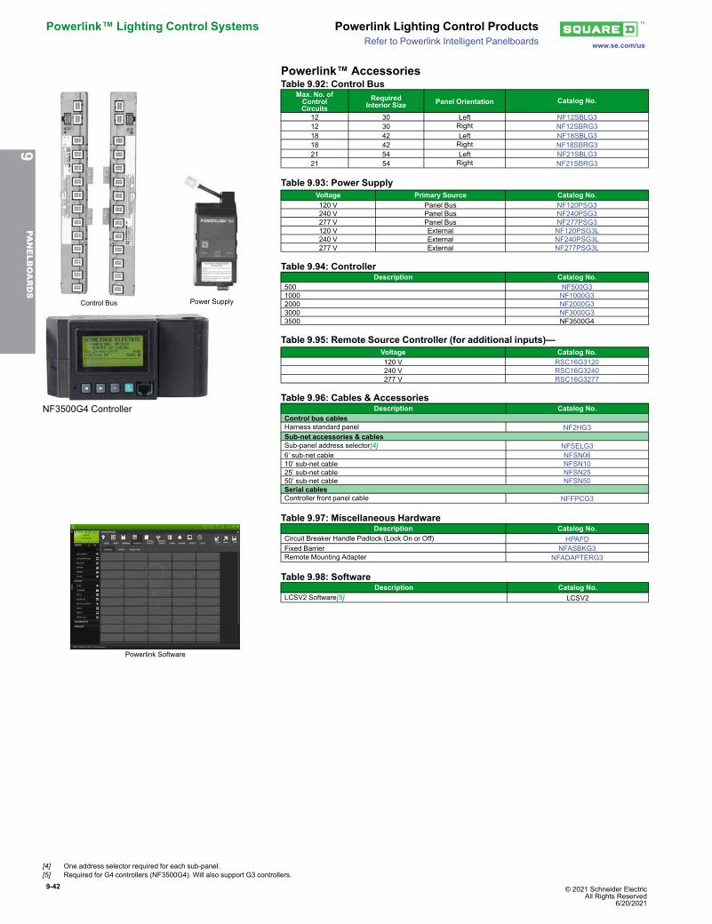
9-42 © 2021 Schneider Electric All Rights Reserved
6/20/2021
Powerlink™ Lighting Control Systems Powerlink Lighting Control Productswww.se.com/usRefer to Powerlink Intelligent Panelboards
Powerlink™ Accessories
Control Bus Power Supply
Table 9.92: Control BusMax. No. ofControlCircuits
RequiredInterior Size Panel Orientation Catalog No.
12 30 Left NF12SBLG312 30 Right NF12SBRG318 42 Left NF18SBLG318 42 Right NF18SBRG321 54 Left NF21SBLG321 54 Right NF21SBRG3
Table 9.93: Power SupplyVoltage Primary Source Catalog No.120 V Panel Bus NF120PSG3240 V Panel Bus NF240PSG3277 V Panel Bus NF277PSG3120 V External NF120PSG3L240 V External NF240PSG3L277 V External NF277PSG3L
NF3500G4 Controller
Table 9.94: ControllerDescription Catalog No.
500 NF500G31000 NF1000G32000 NF2000G33000 NF3000G33500 NF3500G4
Table 9.95: Remote Source Controller (for additional inputs)—Voltage Catalog No.120 V RSC16G3120240 V RSC16G3240277 V RSC16G3277
Table 9.96: Cables & AccessoriesDescription Catalog No.
Control bus cablesHarness standard panel NF2HG3Sub-net accessories & cablesSub-panel address selector[4] NFSELG36’ sub-net cable NFSN0610’ sub-net cable NFSN1025’ sub-net cable NFSN2550’ sub-net cable NFSN50Serial cablesController front panel cable NFFPCG3
Powerlink Software
Table 9.97: Miscellaneous HardwareDescription Catalog No.
Circuit Breaker Handle Padlock (Lock On or Off) HPAFDFixed Barrier NFASBKG3Remote Mounting Adapter NFADAPTERG3
Table 9.98: SoftwareDescription Catalog No.
LCSV2 Software[5] LCSV2
9PA
NELBOARDS
[4] One address selector required for each sub-panel.[5] Required for G4 controllers (NF3500G4). Will also support G3 controllers.
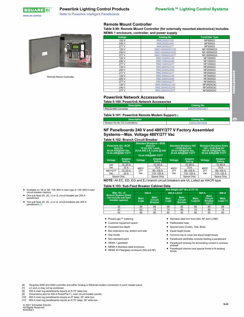
© 2021 Schneider Electric All Rights Reserved6/20/2021
9-43
www.se.com/us
Powerlink Lighting Control Products Powerlink™ Lighting Control SystemsRefer to Powerlink Intelligent Panelboards
Remote Mount Controller
Remote Mount Controller
Table 9.99: Remote Mount Controller (for externally mounted electronics) IncludesNEMA 1 enclosure, controller, and power supply
Voltage Catalog No. Controller Type120 V RMC500G3120 NF500G3240 V RMC500G3240 NF500G3277 V RMC500G3277 NF500G3120 V RMC1000N2G3120 NF1000N2G3240 V RMC1000N2G3240 NF1000N2G3277 V RMC1000N2G3277 NF1000N2G3120 V RMC1000G3120 NF1000G3240 V RMC1000G3240 NF1000G3277 V RMC1000G3277 NF1000G3120 V RMC2000G3120 NF2000G3240 V RMC2000G3240 NF2000G3277 V RMC2000G3277 NF2000G3120 V RMC3000G3120 NF3000G3240 V RMC3000G3240 NF3000G3277 V RMC3000G3277 NF3000G3120 V RMC3000G3C120 NF3000G3C240 V RMC3000G3C240 NF3000G3C277 V RMC3000G3C277 NF3000G3C
Powerlink Network AccessoriesTable 9.100: Powerlink Network Accessories
Description Catalog No.RS232/485 Converter 6382RS485G3KIT
Table 9.101: Powerlink Remote Modem Support[6]Description Catalog No.
Modem Kit (for G3 Controllers) 6382G3MODEM
NF Panelboards 240 V and 480Y/277 V Factory AssembledSystems—Max. Voltage 480Y/277 VacTable 9.102: Branch Circuit Breaker
Powerlink G3—ECBBolt-On
65 kA AIR@240 Vac,14 kA AIR@480 Y/277
Standard Breakers—EDBBolt-On
18 kA AIR 1-pole,25 kA AIR 2 & 3-pole @ 240
V,18 kA AIR@480 Y/277
Standard Breakers HIC—EGB Bolt-On
65 kA AIR@240 Vac,35 kA AIR@480 Y/277
Standard Breakers ExtraHIC—EJB Bolt-On
100 kA AIR@240 Vac,65 kA AIR@480 Y/277
Voltage AmpereRating Voltage Ampere
Rating Voltage AmpereRating Voltage Ampere
Rating240Vac
15–20 A480Y/277Vac
15–60 A480Y/277Vac
15–60 A480Y/277Vac
15–60 A30 A 70 A 70 A 70 A
480Y/277Vac
15–20 A 80–100 A 80–100 A 80–100 A30 A 110–125 A 110–125 A 110–125 A
Space Only Space Only Space Only Space Only
NOTE: All EC, ED, EG and EJ branch circuit breakers are UL Listed as HACR type.
• Available on 1Ø or 3Ø, 125–800 A main lugs or 125–600 A maincircuit breaker interiors
• One sub-feed JD, JG, JJ or JL circuit breaker per 250 Apanelboard
• Two sub-feed JD, JG, JJ or JL circuit breakers per 400 Apanelboard [7]
Table 9.103: Sub-Feed Breaker Cabinet Data
Max. No. ofBranch Spaces (Doesnot include sub-feedbreaker spaces)
Box Height (20" W x 5.75" D)250 A 400 A LA/LH 600 A 800 A
MainLugs
MainCircuitBreaker
MainLugs
MainCircuitBreaker
MainLugs[8]
MainCircuitBreaker[9][10]
MainLugs[11]
30 56 68 68 80 68 80 6842 62 74 74 86 74 86 7454 68 80 80 92 80 92 80
• PowerLogic™ metering
• Customer equipment space
• Increased box depth
• Box extensions top, bottom and side
• Drip hoods
• Non-standard paint
• NEMA 1 gasketed
• NEMA 4 Stainless steel enclosure
• NEMA 4X Fiberglass enclosure (NQ and NF)
• Stainless steel trim front (NQ, NF and I-LINE)
• Padlockable hasp
• Special locks (Corbin, Yale, Best)
• Equal height boxes
• Common trip to cover two equal height boxes
• Panelboard skirthides conduits feeding a panelboard
• Panelboard wireway for terminating conduit in wirewayendwall
• Panelboard interiors and special fronts to fit existingboxes
9PA
NELBOARDS
[6] Requires 2000 and 3000 controller and either Analog or Ethernet modem connection to each master panel.[7] LC and JJ may not be combined.[8] 600 A main lug panelboards require an 8.75" deep box.[9] Dimensions also for 400 A PowerPacT L main circuit breaker panels.[10] 600 A main lug panelboards require an 8" deep, 26” wide box.[11] 800 A main lug panelboards require an 8.75” deep, 26” wide box.
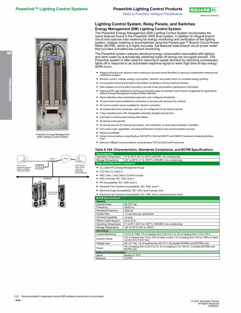
9-44 © 2021 Schneider Electric All Rights Reserved
6/20/2021
Powerlink™ Lighting Control Systems Powerlink Lighting Control Productswww.se.com/usRefer to Powerlink Intelligent Panelboards
Lighting Control System, Relay Panels, and SwitchesEnergy Management (EM) Lighting Control System
Powerlink Energy Management(EM) Lighting Control System
The Powerlink Energy Management (EM) Lighting Control System incorporates thesame features found in the Powerlink 3000 level system, in addition to integral branchcircuit and optional main metering for energy monitoring and verification of the lightingsystem. Integral metering is accomplished using the PowerLogic™ Branch Circuit PowerMeter (BCPM), which is a highly accurate, full-featured multi-branch circuit power meterthat provides unrivalled low-current monitoring.The Powerlink system reduces electrical energy consumption associated with lightingand other loads by automatically switching loads off during non-occupied periods. ThePowerlink system is often ideal for reducing th epeak demand by switching unnecessarylights off in response to an automated response signal or when high time-of-day energytariffs occur.
• Integral individual and optional mains metering to provide utmost flexibility in assurng a sustainable metering andverification program
• Monitors current, voltage, energy consumption, demand, and power factor for complete energy profiling
• Accumulated metering information transmitted via Modbus communications interface
• Data updates occurring within seconds to provide timely preventative maintenance information
• Optional EGX web interface for storing and reporting data via standard web browser (suggested for applicationswithout Energy Management System [EMS] software)
• Alarm indication when parameters approach user-configured thresholds
• 16 hard-wired inputs available for connection to devices with physical dry-contacts
• 64 communication inputs available for network connection
• 16 independent time schedules, each can be configured into 24 distinct periods
• 7-day repeating clock with changeable automatic daylight savings time
• Automatic sunrise/sunset tracking with offsets
• 32 special event periods
• 32 remote sources for sharing input status, time schedules, or zone status between controllers
• Full custom logic capabilities, including full Boolean functions and synchronization services
• RS232 and RS485
• Serial communications using Modbus ASCII/RTU, BACnet MS/TP and DMX512 protocols (metering Modbusonly)
• Ethernet 10BaseTcommunications using Modbus TCP and BACnet/IP protocols
Table 9.104: Characteristics, Standards Compliance, and BCPM SpecificationsCharacteristicsOperating Temperature -5° to 40°C (23° to 104°F) (95%RH, non-condensing)Storage Temperature -20° to 85°C (-4° to 185°F) (<95%RH, non-condensing)Regulatory/Standards Compliance
• UL Listed 916, Energy Management Equip
• FCC Part 15, Class A
• NEC Class 1 and Class 2 Control Circuits• ESD Immunity: IEC 1000, level 4
• RF Susceptibility: IEC 1000, level 3
• Electrical Fast Transient Susceptibility: IEC 1000, level 3
• Electrical Surge Susceptibility: IEC 1000, level 4 (power line)
• Electrical Fast Transient Susceptibility: IEC 1000, level 3 (interconnection lines)BCPM SpecificationsGeneralControl Power 90–277 VacFrequency 50/60 HzSampling Frequency 2560 HzUpdate Rate 1.6 seconds per panelboardOverload Capability 10 kAICRibbon Cable Support Up to 20 ft.Operating Temperature 0° to 60°C (32°C to 122°F) (<95%RH, non-condensing)Storage Temperature -40° to 70°C (-40° to 158°F)AccurancyCurrent Monitoring 0.25 A to 100A: 3% of reading from 0.25 A to 2 A; 2% of reading from 2 A to 100 A
Auxiliary Inputs 2% of reading from 1% to 10% of rated current; 1% of reading from 10% to 100% of ratedcurrent (0 to 0.333 Vac)
Voltage Input 90–277 Vac; 1% of reading from 90–277 L-N (models BCPMA and BCPMB only)
Power 4% of reading from 0.25 A to 2 A; 3% of reading 2 A to 100 A[12] (models BCPMA andBCPM only)
Network CommunicationsSerial Modbus™ RTUEthernet TCP/IP
9PA
NELBOARDS
[12] Recommended for application where EMS software monitoring is not provided.
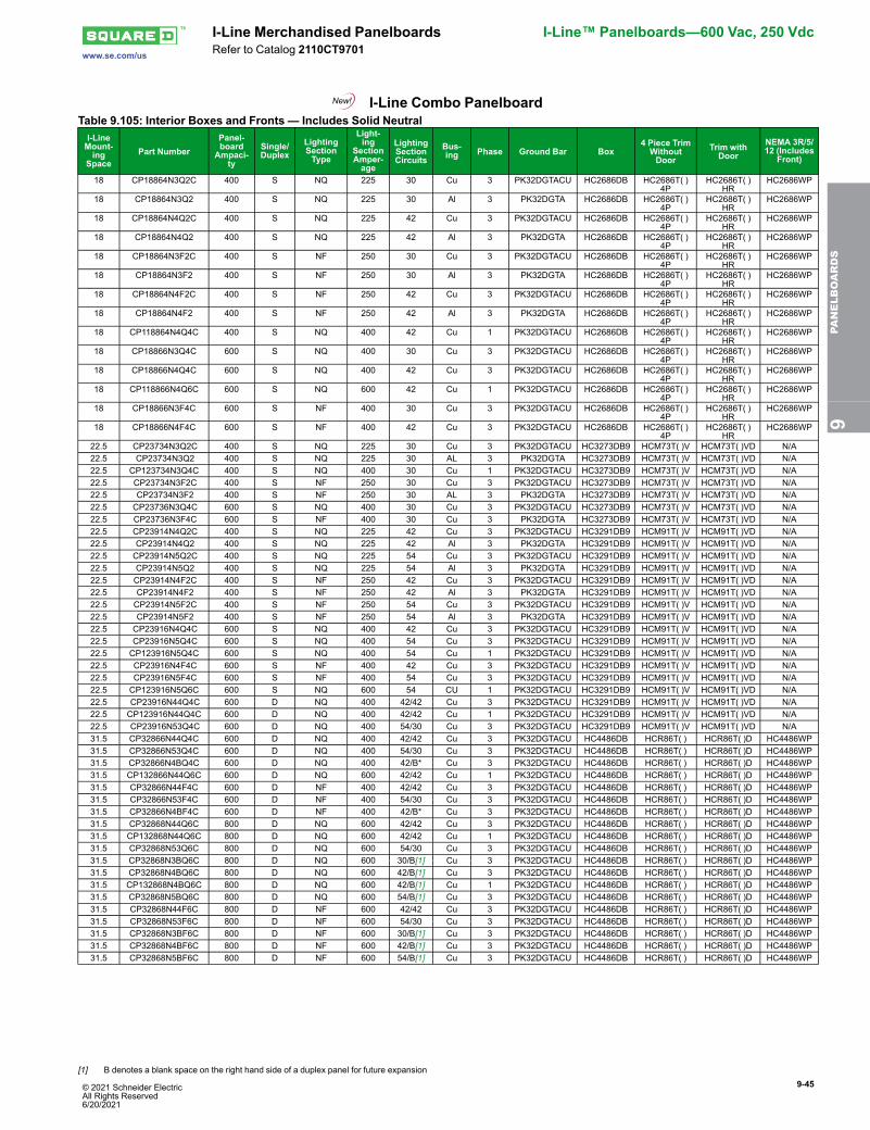
© 2021 Schneider Electric All Rights Reserved6/20/2021
9-45
www.se.com/us
I-Line Merchandised Panelboards I-Line™ Panelboards—600 Vac, 250 VdcRefer to Catalog 2110CT9701
I-Line Combo PanelboardTable 9.105: Interior Boxes and Fronts — Includes Solid NeutralI-LineMount-ing
SpacePart Number
Panel-board
Ampaci-ty
Single/Duplex
LightingSectionType
Light-ing
SectionAmper-age
LightingSectionCircuits
Bus-ing Phase Ground Bar Box
4 Piece TrimWithoutDoor
Trim withDoor
NEMA 3R/5/12 (Includes
Front)
18 CP18864N3Q2C 400 S NQ 225 30 Cu 3 PK32DGTACU HC2686DB HC2686T( )4P
HC2686T( )HR
HC2686WP
18 CP18864N3Q2 400 S NQ 225 30 Al 3 PK32DGTA HC2686DB HC2686T( )4P
HC2686T( )HR
HC2686WP
18 CP18864N4Q2C 400 S NQ 225 42 Cu 3 PK32DGTACU HC2686DB HC2686T( )4P
HC2686T( )HR
HC2686WP
18 CP18864N4Q2 400 S NQ 225 42 Al 3 PK32DGTA HC2686DB HC2686T( )4P
HC2686T( )HR
HC2686WP
18 CP18864N3F2C 400 S NF 250 30 Cu 3 PK32DGTACU HC2686DB HC2686T( )4P
HC2686T( )HR
HC2686WP
18 CP18864N3F2 400 S NF 250 30 Al 3 PK32DGTA HC2686DB HC2686T( )4P
HC2686T( )HR
HC2686WP
18 CP18864N4F2C 400 S NF 250 42 Cu 3 PK32DGTACU HC2686DB HC2686T( )4P
HC2686T( )HR
HC2686WP
18 CP18864N4F2 400 S NF 250 42 Al 3 PK32DGTA HC2686DB HC2686T( )4P
HC2686T( )HR
HC2686WP
18 CP118864N4Q4C 400 S NQ 400 42 Cu 1 PK32DGTACU HC2686DB HC2686T( )4P
HC2686T( )HR
HC2686WP
18 CP18866N3Q4C 600 S NQ 400 30 Cu 3 PK32DGTACU HC2686DB HC2686T( )4P
HC2686T( )HR
HC2686WP
18 CP18866N4Q4C 600 S NQ 400 42 Cu 3 PK32DGTACU HC2686DB HC2686T( )4P
HC2686T( )HR
HC2686WP
18 CP118866N4Q6C 600 S NQ 600 42 Cu 1 PK32DGTACU HC2686DB HC2686T( )4P
HC2686T( )HR
HC2686WP
18 CP18866N3F4C 600 S NF 400 30 Cu 3 PK32DGTACU HC2686DB HC2686T( )4P
HC2686T( )HR
HC2686WP
18 CP18866N4F4C 600 S NF 400 42 Cu 3 PK32DGTACU HC2686DB HC2686T( )4P
HC2686T( )HR
HC2686WP
22.5 CP23734N3Q2C 400 S NQ 225 30 Cu 3 PK32DGTACU HC3273DB9 HCM73T( )V HCM73T( )VD N/A22.5 CP23734N3Q2 400 S NQ 225 30 AL 3 PK32DGTA HC3273DB9 HCM73T( )V HCM73T( )VD N/A22.5 CP123734N3Q4C 400 S NQ 400 30 Cu 1 PK32DGTACU HC3273DB9 HCM73T( )V HCM73T( )VD N/A22.5 CP23734N3F2C 400 S NF 250 30 Cu 3 PK32DGTACU HC3273DB9 HCM73T( )V HCM73T( )VD N/A22.5 CP23734N3F2 400 S NF 250 30 AL 3 PK32DGTA HC3273DB9 HCM73T( )V HCM73T( )VD N/A22.5 CP23736N3Q4C 600 S NQ 400 30 Cu 3 PK32DGTACU HC3273DB9 HCM73T( )V HCM73T( )VD N/A22.5 CP23736N3F4C 600 S NF 400 30 Cu 3 PK32DGTA HC3273DB9 HCM73T( )V HCM73T( )VD N/A22.5 CP23914N4Q2C 400 S NQ 225 42 Cu 3 PK32DGTACU HC3291DB9 HCM91T( )V HCM91T( )VD N/A22.5 CP23914N4Q2 400 S NQ 225 42 Al 3 PK32DGTA HC3291DB9 HCM91T( )V HCM91T( )VD N/A22.5 CP23914N5Q2C 400 S NQ 225 54 Cu 3 PK32DGTACU HC3291DB9 HCM91T( )V HCM91T( )VD N/A22.5 CP23914N5Q2 400 S NQ 225 54 Al 3 PK32DGTA HC3291DB9 HCM91T( )V HCM91T( )VD N/A22.5 CP23914N4F2C 400 S NF 250 42 Cu 3 PK32DGTACU HC3291DB9 HCM91T( )V HCM91T( )VD N/A22.5 CP23914N4F2 400 S NF 250 42 Al 3 PK32DGTA HC3291DB9 HCM91T( )V HCM91T( )VD N/A22.5 CP23914N5F2C 400 S NF 250 54 Cu 3 PK32DGTACU HC3291DB9 HCM91T( )V HCM91T( )VD N/A22.5 CP23914N5F2 400 S NF 250 54 Al 3 PK32DGTA HC3291DB9 HCM91T( )V HCM91T( )VD N/A22.5 CP23916N4Q4C 600 S NQ 400 42 Cu 3 PK32DGTACU HC3291DB9 HCM91T( )V HCM91T( )VD N/A22.5 CP23916N5Q4C 600 S NQ 400 54 Cu 3 PK32DGTACU HC3291DB9 HCM91T( )V HCM91T( )VD N/A22.5 CP123916N5Q4C 600 S NQ 400 54 Cu 1 PK32DGTACU HC3291DB9 HCM91T( )V HCM91T( )VD N/A22.5 CP23916N4F4C 600 S NF 400 42 Cu 3 PK32DGTACU HC3291DB9 HCM91T( )V HCM91T( )VD N/A22.5 CP23916N5F4C 600 S NF 400 54 Cu 3 PK32DGTACU HC3291DB9 HCM91T( )V HCM91T( )VD N/A22.5 CP123916N5Q6C 600 S NQ 600 54 CU 1 PK32DGTACU HC3291DB9 HCM91T( )V HCM91T( )VD N/A22.5 CP23916N44Q4C 600 D NQ 400 42/42 Cu 3 PK32DGTACU HC3291DB9 HCM91T( )V HCM91T( )VD N/A22.5 CP123916N44Q4C 600 D NQ 400 42/42 Cu 1 PK32DGTACU HC3291DB9 HCM91T( )V HCM91T( )VD N/A22.5 CP23916N53Q4C 600 D NQ 400 54/30 Cu 3 PK32DGTACU HC3291DB9 HCM91T( )V HCM91T( )VD N/A31.5 CP32866N44Q4C 600 D NQ 400 42/42 Cu 3 PK32DGTACU HC4486DB HCR86T( ) HCR86T( )D HC4486WP31.5 CP32866N53Q4C 600 D NQ 400 54/30 Cu 3 PK32DGTACU HC4486DB HCR86T( ) HCR86T( )D HC4486WP31.5 CP32866N4BQ4C 600 D NQ 400 42/B* Cu 3 PK32DGTACU HC4486DB HCR86T( ) HCR86T( )D HC4486WP31.5 CP132866N44Q6C 600 D NQ 600 42/42 Cu 1 PK32DGTACU HC4486DB HCR86T( ) HCR86T( )D HC4486WP31.5 CP32866N44F4C 600 D NF 400 42/42 Cu 3 PK32DGTACU HC4486DB HCR86T( ) HCR86T( )D HC4486WP31.5 CP32866N53F4C 600 D NF 400 54/30 Cu 3 PK32DGTACU HC4486DB HCR86T( ) HCR86T( )D HC4486WP31.5 CP32866N4BF4C 600 D NF 400 42/B* Cu 3 PK32DGTACU HC4486DB HCR86T( ) HCR86T( )D HC4486WP31.5 CP32868N44Q6C 800 D NQ 600 42/42 Cu 3 PK32DGTACU HC4486DB HCR86T( ) HCR86T( )D HC4486WP31.5 CP132868N44Q6C 800 D NQ 600 42/42 Cu 1 PK32DGTACU HC4486DB HCR86T( ) HCR86T( )D HC4486WP31.5 CP32868N53Q6C 800 D NQ 600 54/30 Cu 3 PK32DGTACU HC4486DB HCR86T( ) HCR86T( )D HC4486WP31.5 CP32868N3BQ6C 800 D NQ 600 30/B[1] Cu 3 PK32DGTACU HC4486DB HCR86T( ) HCR86T( )D HC4486WP31.5 CP32868N4BQ6C 800 D NQ 600 42/B[1] Cu 3 PK32DGTACU HC4486DB HCR86T( ) HCR86T( )D HC4486WP31.5 CP132868N4BQ6C 800 D NQ 600 42/B[1] Cu 1 PK32DGTACU HC4486DB HCR86T( ) HCR86T( )D HC4486WP31.5 CP32868N5BQ6C 800 D NQ 600 54/B[1] Cu 3 PK32DGTACU HC4486DB HCR86T( ) HCR86T( )D HC4486WP31.5 CP32868N44F6C 800 D NF 600 42/42 Cu 3 PK32DGTACU HC4486DB HCR86T( ) HCR86T( )D HC4486WP31.5 CP32868N53F6C 800 D NF 600 54/30 Cu 3 PK32DGTACU HC4486DB HCR86T( ) HCR86T( )D HC4486WP31.5 CP32868N3BF6C 800 D NF 600 30/B[1] Cu 3 PK32DGTACU HC4486DB HCR86T( ) HCR86T( )D HC4486WP31.5 CP32868N4BF6C 800 D NF 600 42/B[1] Cu 3 PK32DGTACU HC4486DB HCR86T( ) HCR86T( )D HC4486WP31.5 CP32868N5BF6C 800 D NF 600 54/B[1] Cu 3 PK32DGTACU HC4486DB HCR86T( ) HCR86T( )D HC4486WP
9PA
NELBOARDS
[1] B denotes a blank space on the right hand side of a duplex panel for future expansion
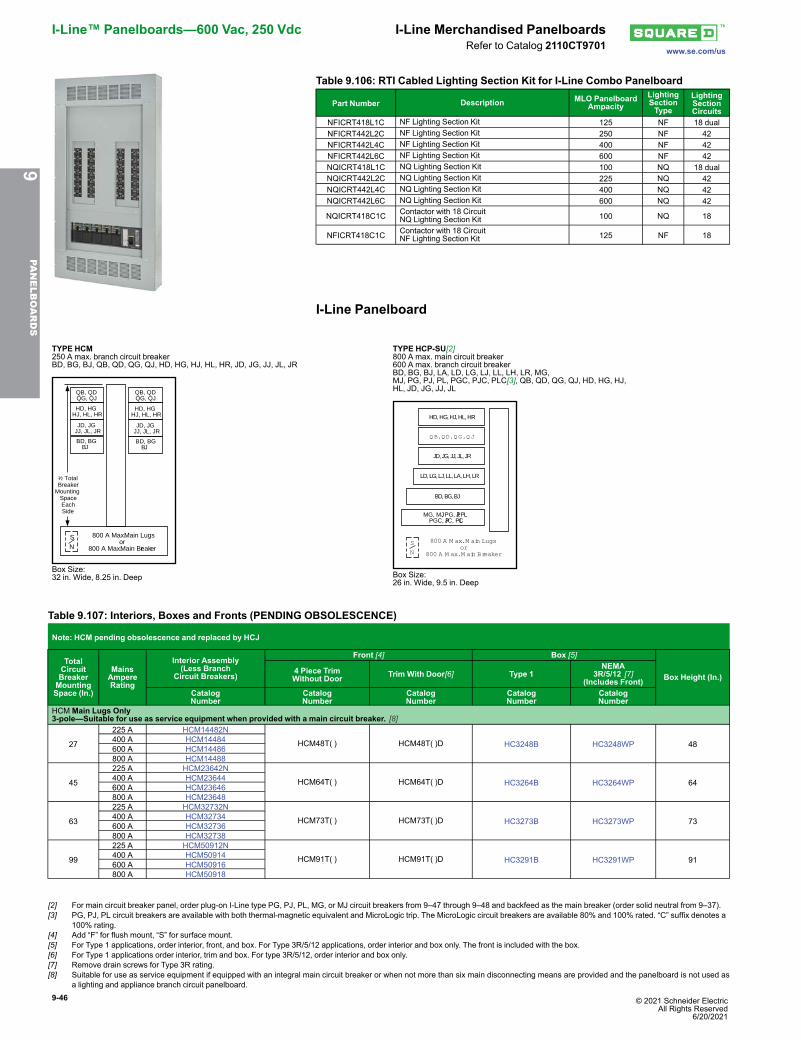
9-46 © 2021 Schneider Electric All Rights Reserved
6/20/2021
I-Line™ Panelboards—600 Vac, 250 Vdc I-Line Merchandised Panelboardswww.se.com/usRefer to Catalog 2110CT9701
Table 9.106: RTI Cabled Lighting Section Kit for I-Line Combo Panelboard
Part Number Description MLO PanelboardAmpacity
LightingSectionType
LightingSectionCircuits
NFICRT418L1C NF Lighting Section Kit 125 NF 18 dualNFICRT442L2C NF Lighting Section Kit 250 NF 42NFICRT442L4C NF Lighting Section Kit 400 NF 42NFICRT442L6C NF Lighting Section Kit 600 NF 42NQICRT418L1C NQ Lighting Section Kit 100 NQ 18 dualNQICRT442L2C NQ Lighting Section Kit 225 NQ 42NQICRT442L4C NQ Lighting Section Kit 400 NQ 42NQICRT442L6C NQ Lighting Section Kit 600 NQ 42
NQICRT418C1C Contactor with 18 CircuitNQ Lighting Section Kit 100 NQ 18
NFICRT418C1C Contactor with 18 CircuitNF Lighting Section Kit 125 NF 18
I-Line Panelboard
TYPE HCM250 A max. branch circuit breakerBD, BG, BJ, QB, QD, QG, QJ, HD, HG, HJ, HL, HR, JD, JG, JJ, JL, JR
HD, HGHJ, HL, HR
JD, JGJJ, JL, JR
HD, HGHJ, HL, HR
JD, JGJJ, JL, JR
800 A Max. Main Lugsor
800 A Max. Main Breaker
SN
1⁄2 TotalBreaker
MountingSpaceEachSide
QB, QDQG, QJ
QB, QDQG, QJ
BD, BGBJ
BD, BGBJ
Box Size:32 in. Wide, 8.25 in. Deep
TYPE HCP-SU[2]800 A max. main circuit breaker600 A max. branch circuit breakerBD, BG, BJ, LA, LD, LG, LJ, LL, LH, LR, MG,MJ, PG, PJ, PL, PGC, PJC, PLC[3], QB, QD, QG, QJ, HD, HG, HJ,HL, JD, JG, JJ, JL
S
N
800 A M ax. M ain Lugsor
800 A M ax. M ain Breaker
HD, HG, HJ, HL, HR
Q B, Q D, Q G , Q J
JD, JG, JJ, JL, JR
LD, LG, LJ, LL, LA, LH, LR
BD, BG, BJ
MG, MJ, PG, PJ, PL PGC, PJC, PLC
Box Size:26 in. Wide, 9.5 in. Deep
Table 9.107: Interiors, Boxes and Fronts (PENDING OBSOLESCENCE)
Note: HCM pending obsolescence and replaced by HCJ
TotalCircuitBreakerMountingSpace (In.)
MainsAmpereRating
Interior Assembly(Less Branch
Circuit Breakers)
Front [4] Box [5]
Box Height (In.)4 Piece TrimWithout Door Trim With Door[6] Type 1
NEMA3R/5/12 [7]
(Includes Front)CatalogNumber
CatalogNumber
CatalogNumber
CatalogNumber
CatalogNumber
HCMMain Lugs Only3-pole—Suitable for use as service equipment when provided with a main circuit breaker. [8]
27
225 A HCM14482N
HCM48T( ) HCM48T( )D HC3248B HC3248WP 48400 A HCM14484600 A HCM14486800 A HCM14488
45
225 A HCM23642N
HCM64T( ) HCM64T( )D HC3264B HC3264WP 64400 A HCM23644600 A HCM23646800 A HCM23648
63
225 A HCM32732N
HCM73T( ) HCM73T( )D HC3273B HC3273WP 73400 A HCM32734600 A HCM32736800 A HCM32738
99
225 A HCM50912N
HCM91T( ) HCM91T( )D HC3291B HC3291WP 91400 A HCM50914600 A HCM50916800 A HCM50918
9PA
NELBOARDS
[2] For main circuit breaker panel, order plug-on I-Line type PG, PJ, PL, MG, or MJ circuit breakers from 9–47 through 9–48 and backfeed as the main breaker (order solid neutral from 9–37).[3] PG, PJ, PL circuit breakers are available with both thermal-magnetic equivalent and MicroLogic trip. The MicroLogic circuit breakers are available 80% and 100% rated. “C” suffix denotes a
100% rating.[4] Add “F” for flush mount, “S” for surface mount.[5] For Type 1 applications, order interior, front, and box. For Type 3R/5/12 applications, order interior and box only. The front is included with the box.[6] For Type 1 applications order interior, trim and box. For type 3R/5/12, order interior and box only.[7] Remove drain screws for Type 3R rating.[8] Suitable for use as service equipment if equipped with an integral main circuit breaker or when not more than six main disconnecting means are provided and the panelboard is not used as
a lighting and appliance branch circuit panelboard.
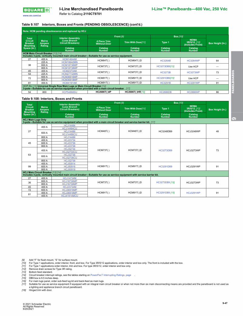
© 2021 Schneider Electric All Rights Reserved6/20/2021
9-47
www.se.com/us
I-Line Merchandised Panelboards I-Line™ Panelboards—600 Vac, 250 VdcRefer to Catalog 2110CT9701
Table 9.107 Interiors, Boxes and Fronts (PENDING OBSOLESCENCE) (cont'd.)
Note: HCM pending obsolescence and replaced by HCJ
TotalCircuitBreakerMountingSpace (In.)
MainsAmpereRating
Interior Assembly(Less Branch
Circuit Breakers)
Front [9] Box [10]
Box Height (In.)4 Piece TrimWithout Door Trim With Door[11] Type 1
NEMA3R/5/12 [12]
(Includes Front)CatalogNumber
CatalogNumber
CatalogNumber
CatalogNumber
CatalogNumber
HCM Main Circuit Breaker [13] [14]Includes 3-pole, vertically mounted main circuit breaker—Suitable for use as service equipment.
27 400 A HCM14644M HCM64T( ) HCM64T( )D HC3264B HC3264WP 64
36225 A HCM18642MN600 A HCM18736MP HCM73T( ) HCM73T( )D HC3273DB9[15] Use HCP —800 A HCM18738MP
45 400 A HCM23734M HCM73T( ) HCM73T( )D HC3273B HC3273WP 7354 225 A HCM27732MN
72 600 A HCM36916MP HCM91T( ) HCM91T( )D HC3291DB9[15] Use HCP —800 A HCM36918MP81 400 A HCM41914M HCM91T( ) HCM91T( )D HC3291B HC3291WP 91
HCP-SU [16] Universal Single Row Main Lugs or Main Circuit Breaker [14]3-pole—Suitable for use as service equipment when provided with a main circuit breaker. [17]
54 800 HCP54868SU HC2686T( )4P HC2686T( )HR[18] HC2686DB HC2886WP 86
Table 9.108: Interiors, Boxes and Fronts
TotalCircuitBreakerMountingSpace (In.)
MainsAmpereRating
Interior Assembly(Less Branch
Circuit Breakers)
Front [9] Box [10]
Box Height (In.)4 Piece TrimWithout Door Trim With Door[11] Type 1
NEMA3R/5/12 [12]
(Includes Front)CatalogNumber
CatalogNumber
CatalogNumber
CatalogNumber
CatalogNumber
HCJ Main Lugs Only3-pole—Suitable for use as service equipment when provided with a main circuit breaker and service barrier kit. [17]
27
400 A HCJ14484
HCM48T( ) HCM48T( )D HC3248DB9 HCJ3248WP 48HCJ14484CU
600 A HCJ14486HCJ14486CU
800 A HCJ14488
45400 A HCJ23734
HCM73T( ) HCM73T( )D HC3273DB9 HCJ3273WP 73
600 A HCJ23736800 A HCJ23738
63
400 A HCJ32734HCJ32734CU
600 A HCJ32736HCJ32736CU
800 A HCJ32738
99400 A HCJ50914
HCM91T( ) HCM91T( )D HC3291DB9 HCJ3291WP 91600 A HCJ50916800 A HCJ50918
HCJ Main Circuit Breaker [13] [14]Includes 3-pole, vertically mounted main circuit breaker—Suitable for use as service equipment with service barrier kit.
27 400 A HCJ14734M
HCM73T( ) HCM73T( )D HC3273DB9 [15] HCJ3273WP 7336 600 A HCJ18736MP800 A HCJ18738MP
45 400 A HCJ23734M72 600 A HCJ36916MP
HCM91T( ) HCM91T( )D HC3291DB9 [15] HCJ3291WP 9181 400 A HCJ36918MP400 A HCJ41914MCU
9PA
NELBOARDS
[9] Add “F” for flush mount, “S” for surface mount.[10] For Type 1 applications, order interior, front, and box. For Type 3R/5/12 applications, order interior and box only. The front is included with the box.[11] For Type 1 applications order interior, trim and box. For type 3R/5/12, order interior and box only.[12] Remove drain screws for Type 3R rating.[13] Bottom feed standard.[14] Circuit breaker interrupt ratings, see the tables starting on PowerPacT Interrupting Ratings, page .[15] DB9 box is 9.5 inches deep.[16] For main lugs panel, order sub-feed lug kit and back-feed as main lugs.[17] Suitable for use as service equipment if equipped with an integral main circuit breaker or when not more than six main disconnecting means are provided and the panelboard is not used as
a lighting and appliance branch circuit panelboard.[18] Hinged trim with door.
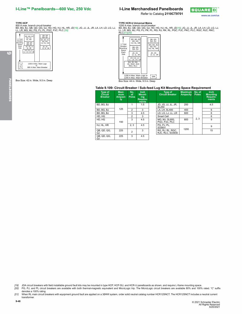
9-48 © 2021 Schneider Electric All Rights Reserved
6/20/2021
I-Line™ Panelboards—600 Vac, 250 Vdc I-Line Merchandised Panelboardswww.se.com/usRefer to Catalog 2110CT9701
TYPE HCP800 A max. branch circuit breakerBD, BG, BJ, QB, QD, QG, QJ, HD, HG, HJ, HL, HR, JD[19], JG, JJ, JL, JR, LA, LH, LD, LG, LJ,LL, LR, MG, MJ, PG, PJ, PL, PGC, PJC, PLC [20]
JD, JG, JJJL, JR
JD, JG JJ, JL, JR
1200 A Max. Main Lugsor
800 A Max. Main Breaker
QB, QDQG, QJ
BD, BG, BJHG, HJ HL, HR BD, BG, BJ,
HD, HGHJ, HL, HR
1⁄2 TotalBreaker
MountingSpaceEachSide
QB, QDQG, QJ
SN
LD, LG, LJLL, LA, LH, LR
Box Size: 42 in. Wide, 9.5 in. Deep
TYPE HCR-U Universal Mains1200 A max. branch circuit breakerBD, BG, BJ, QB, QD, QG, QJ, HD, HG, HJ, HL, HR, JD[19], JG, JJ, JL, JR, LA, LH, LD, LG, LJ,LL, LR, MG, MJ, PG, PJ, PK, PL, RG, RJ, RK, RL, PGC, PJC, PKC, PLC, RGC, RJC, RKC,RLC[21][20]
RG, RJ, RK, RL, RGC, RJC
RKC, RLC
1⁄2 TotalBreaker
MountingSpaceEachSide
LD, LG, LJLL, LA, LH, LR
QB, QDQG, QJ
QB, QDQG, QJ
1200 A Max. Main Lugs or1200 A Max. Main Breaker
JD, JG JJ, JL, JR
JD, JG JJ, JL, JR
BD, BG, BJHD, HG
HJ, HL, HRBD, BG, BJ
HD, HGHJ, HL, HR
S/N
Box Size: 44 in. Wide, 9.5 in. Deep
Table 9.109: Circuit Breaker / Sub-feed Lug Kit Mounting Space RequirementType ofCircuitBreaker
Maxi-mum
Ampaci-ty
No.of
Poles
InchMount-ing
Require-ments
Type ofCircuit Breaker
MaximumAmpacity
No. ofPoles
InchMountingRequire-ments
BD, BG, BJ
125
1 1.5 JD, JG, JJ, JL, JR,SL250
250
2, 3
4.5
BD, BG, BJ 2 3 LA, LH, SL400 400 6BD, BG, BJ 3 4.5 LD, LG, LJ, LL, LR 600 6HD, HG
150
2 3 Smart Cell 6HD, HG 3 4.5 MG, MJ, SL800,
PGC, PJC, PLC800 9
HJ, HL, HR 2, 3 4.5 PG, PJ, PL,S33931
12009
QB, QD, QG,QJ
225 2 3 RG, RJ, RL, RGC,RJC, RLC, S33930
15
QB, QD, QG,QJ
225 3 4.5
9PA
NELBOARDS
[19] JDA circuit breakers with field installable ground fault kits may be mounted in type HCP, HCP-SU, and HCR-U panelboards as shown, and require L-frame mounting space.[20] PG, PJ, and PL circuit breakers are available with both thermal-magnetic equivalent and MicroLogic trip. The MicroLogic circuit breakers are available 80% and 100% rated. “C” suffix
denotes a 100% rating.[21] When RL main circuit breakers with equipment ground fault are applied on a 3Ø4W system, order solid neutral catalog number HCR12SNCT. The HCR12SNCT includes a neutral current
transformer.
© 2021 Schneider Electric All Rights Reserved6/20/2021
9-49
www.se.com/us
I-Line Merchandised Panelboards I-Line™ Panelboards—600 Vac, 250 VdcRefer to Catalog 2110CT9701
Table 9.110: (1200 A Interiors Include solid neutral, all others without solid neutral) [22]TotalCircuitBreakerMtg.Space(In.)
MainsAmp.Rating
Max.No. ofLC, MJ,PL, RLCircuitBreakers
Interior Assembly(Less Branch Circuit Breakers)
Front [23]Box [24] Box
Height(In.)
4 Piece TrimWithout Door [25] Trim With Door
CatalogNumber
CatalogNumber
CatalogNumber
CatalogNumber
HCP Main Lugs Only—3-poleSuitable for use as service equipment when provided with a main circuit breaker. [26]
27
400
1PL
HCP14504
HCW50T( ) HCW50T( )D HC4250DB 50 600 HCP14506 800 HCP145081200 HCP145012N
45
400
2PL
HCP23594
HCW59T( ) HCW59T( )D HC4259DB 59 600 HCP23596 800 HCP235981200 HCP235912N
63
400
3PL
HCP32684
HCW68T( ) HCW68T( )D HC4268DB 68 600 HCP32686 800 HCP326881200 HCP326812N
99
400
5PL
HCP50864
HCW86T( ) HCW86T( )D HC4286DB 86 600 HCP50866 800 HCP508681200 HCP508612N
HCP Main Circuit Breaker[27]—Includes 3-poleVertically mounted main circuit breaker—Suitable for use as service equipment.
36 600 2LC HCP18686M HCW68T( ) HCW68T( )D HC4268DB 68800 HCP18688M
72 600 4LC HCP36866M HCW86T( ) HCW86T( )D HC4286DB 86800 HCP36868MHCR-U Universal Main Lugs or Main Circuit Breaker [23]—3-poleSuitable for use as service equipment when provided with a main circuit breaker.For Main Lugs panel, order sub-feed lug kit catalog number S33930 and back feed as main lugs.For Main Circuit Breaker panel, order plug-on I-Line type PG, PJ, PL, RGC, RJC, or RLC [28] circuit breakers from page 9-53,and back feed as the main circuit breaker. (Order solid neutral separately)
108 [29] 1200 6PL or 3RLC HCR548612U HCR86T( )[30] HCR86T( )D HC4486DB 86
Table 9.111: Main Circuit Breaker Interiors —Standard Frame Types [27]
Main Circuit Breaker Ampacity PanelboardType
Factory SuppliedMain Circuit Breaker
225 HCM JDA36225400 HCM LAP36400MB600or800
HCM, HCPMGP36600
orMGP36800
Table 9.112: Standard Copper Bus InteriorsType Main Ampacity
HCM, HCP-SU 800HCP, HCR-U 800 and Above
NOTE: Merchandised copper interiors are not available in all ampacities.
9PA
NELBOARDS
[22] Order solid neutral from Table 9.113 I-Line Merchandised Panelboard Accessories, page 9-50.[23] Add “F” for flush mount, “S” for surface mount.[24] For 42 in. wide weatherproof enclosures, see Table 9.119 Type 3R/5/12 Enclosures, page 9-51[25] Add-on door kit available. Example: For HCW50TS trim kit, order HCW50D door kit.[26] Suitable for use as service equipment if equipped with an integral main circuit breaker or when not more than six main disconnecting means are provided and the panelboard is not used as
a lighting and appliance branch circuit panelboard.[27] Circuit breaker interrupt ratings, see the tables starting on PowerPacT Interrupting Ratings, page .[28] When RL main circuit breakers with equipment ground fault are applied on a 3Ø4W system, order solid neutral catalog number HCR12SNCT.
The HCR12SNCT includes a neutral current transformer.[29] 15 in. of mounting space is taken up by the back fed main lug kit or RG, RJ, RL main circuit breaker, leaving 93 in. of branch circuit breaker mounting space.[30] Add-on door kit available. Example: For HCR86TS trim kit, order HCW86D door kit.
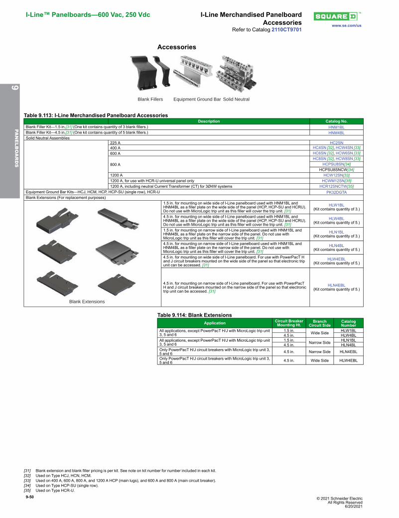
9-50 © 2021 Schneider Electric All Rights Reserved
6/20/2021
I-Line™ Panelboards—600 Vac, 250 Vdc I-Line Merchandised PanelboardAccessories www.se.com/us
Refer to Catalog 2110CT9701
Accessories
Blank Fillers Equipment Ground Bar Solid Neutral
Table 9.113: I-Line Merchandised Panelboard AccessoriesDescription Catalog No.
Blank Filler Kit—1.5 in.[31] (One kit contains quantity of 3 blank fillers.) HNM1BLBlank Filler Kit—4.5 in.[31] (One kit contains quantity of 5 blank fillers.) HNM4BLSolid Neutral Assemblies
225 A HC2SN400 A HC4SN [32], HCW4SN [33]600 A HC6SN [32], HCW6SN [33]
800 AHC8SN [32], HCW8SN [33]
HCPSU8SN[34]HCPSU8SNCW[34]
1200 A HCW12SN[33]1200 A, for use with HCR-U universal panel only HCWM12SN[35]1200 A, including neutral Current Transformer (CT) for 3Ø4W systems HCR12SNCTW[35]
Equipment Ground Bar Kits—HCJ, HCM, HCP, HCP-SU (single row), HCR-U PK32DGTABlank Extensions (For replacement purposes)
Blank Extensions
1.5 in. for mounting on wide side of I-Line panelboard used with HNM1BL andHNM4BL as a filler plate on the wide side of the panel (HCP, HCP-SU and HCRU).Do not use with MicroLogic trip unit as this filler will cover the trip unit. [31]
HLW1BL(Kit contains quantity of 3.)
4.5 in. for mounting on wide side of I-Line panelboard used with HNM1BL andHNM4BL as a filler plate on the wide side of the panel (HCP, HCP-SU and HCRU).Do not use with MicroLogic trip unit as this filler will cover the trip unit. [31]
HLW4BL(Kit contains quantity of 5.)
1.5 in. for mounting on narrow side of I-Line panelboard used with HNM1BL andHNM4BL as a filler plate on the narrow side of the panel. Do not use withMicroLogic trip unit as this filler will cover the trip unit. [31]
HLN1BL(Kit contains quantity of 3.)
4.5 in. for mounting on narrow side of I-Line panelboard used with HNM1BL andHNM4BL as a filler plate on the narrow side of the panel. Do not use withMicroLogic trip unit as this filler will cover the trip unit. [31]
HLN4BL(Kit contains quantity of 5.)
4.5 in. for mounting on wide side of I-Line panelboard. For use with PowerPacT Hand J circuit breakers mounted on the wide side of the panel so that electronic tripunit can be accessed. [31]
HLW4EBL(Kit contains quantity of 5.)
4.5 in. for mounting on narrow side of I-Line panelboard. For use with PowerPacTH and J circuit breakers mounted on the narrow side of the panel so that electronictrip unit can be accessed. [31]
HLN4EBL(Kit contains quantity of 5.)
Table 9.114: Blank ExtensionsApplication Circuit Breaker
Mounting Ht.Branch
Circuit SideCatalogNumber
All applications, except PowerPacT H/J with MicroLogic trip unit3, 5 and 6
1.5 in. Wide Side HLW1BL4.5 in. HLW4BL
All applications, except PowerPacT H/J with MicroLogic trip unit3, 5 and 6
1.5 in. Narrow Side HLN1BL4.5 in. HLN4BL
Only PowerPacT H/J circuit breakers with MicroLogic trip unit 3,5 and 6 4.5 in. Narrow Side HLN4EBL
Only PowerPacT H/J circuit breakers with MicroLogic trip unit 3,5 and 6 4.5 in. Wide Side HLW4EBL
9PA
NELBOARDS
[31] Blank extension and blank filler pricing is per kit. See note on kit number for number included in each kit.[32] Used on Type HCJ, HCN, HCM.[33] Used on 400 A, 600 A, 800 A, and 1200 A HCP (main lugs), and 600 A and 800 A (main circuit breaker).[34] Used on Type HCP-SU (single row).[35] Used on Type HCR-U.
© 2021 Schneider Electric All Rights Reserved6/20/2021
9-51
www.se.com/us
I-Line Merchandised PanelboardAccessories
I-Line™ Panelboards—600 Vac, 250 Vdc
Refer to Catalog 2110CT9701
Table 9.115: UL Service Entrance Barriers for I-Line Panelboards withBackfeed Main Circuit BreakerI-Line Panelboard Type Backfeed Main Circuit Breaker Catalog Number [36]
HCM/HCJ H, J ILBFMHCJHULC
HCPH, J ILBFMHCPHJULC
LA, LH, PowerPacT L ILBFMHCPLULCM, P ILBFMHCPMPULC
HCR
LA, LH, PowerPacT L ILBFMHCRLULCM ILBFMHCRMULCP ILBFMHCRPULCR ILBFMHCRRULC
(NOTE: Barriers are required by 2017 version of NFPA70—National Electric Code. Both the 2017UL67 and 2017 NFPA70 allow an exception for service entrance panelboards with more than onedisconnect.)
Table 9.116: UL Service Entrance Barrier Kits for I-Line VerticalMounted Mains
MainCircuitBreaker
Determining FactorsCatalogNumber[36]
MG, MJ
4 wires per phase(for breakers with AL1200P24K or CU1200P24K lug kit) ILMLC4W
3 wires per phase(for breakers with AL80023K or CU80023K lug kit) ILMLC3W
2 wires per phase(for breakers with AL800P6K or AL800P7K lug kit) ILMLC2W
PowerPacTL All instances PPLLC
LA/LH All instances LALLC(NOTE: Barriers are required by 2017 version of NFPA70—National Electric Code)
Table 9.117: Solid Neutral Lug Quantities and SizesSolid Neutral Assembly Terminal Wire RangeHC2SN (1) 6 - 300, (9) #1/0 - 14, (45) #4 - 14HC4SN (7) 6 - 350, (45) #4 - 14HC6SN (7) 6 - 350, (9) #1/0 - 14, (28) #4 - 14HC8SN (7) 6 - 350, (9) #1/0 - 14, (34) #4 - 14HCPSU8SN (4) 3/0 - 600, (7) 6 - 350, (9) #1/0 - 14, (34) #4 - 14,HCW4SN (2) 4 - 600, (7) 6 - 350, (45) #4 - 14HCW6SN (4) 3/0 - 750, (7) 6 - 350, (9) #1/0 - 14, (34) #4 - 14HCW8SN (4) 3/0 - 750, (7) 6 - 350, (9) #1/0 - 14, (34) #4 - 14HCW12SN (4) 3/0 - 750, (7) 6 - 350, (9) #1/0 - 14, (34) #4 - 14HCWM12SN (4) 3/0 - 750, (7) 6 - 350, (9) #1/0 - 14, (34) #4 - 14HC6SNALCU (7) 6 - 350, (9) #1/0 - 14, (28) #4 - 14HC8SNALCU (7) 6 - 350, (9) #1/0 - 14, (34) #4 - 14HCPSU8SNALCU (4) 3/0 - 600, (7) 6 - 350, (9) #1/0 - 14, (34) #4 - 14HCP4SNALCU (2) 4 - 600, (7) 6 - 350, (45) #4 - 14HCP6SNALCU (4) 3/0 - 750, (7) 6 - 350, (9) #1/0 - 14, (34) #4 - 14HCP8SNALCU (4) 3/0 - 750, (7) 6 - 350, (9) #1/0 - 14, (34) #4 - 14HCP12SNALCU (4) 3/0 - 750, (7) 6 - 350, (9) #1/0 - 14, (34) #4 - 14HCR12SNALCU (4) 3/0 - 750, (7) 6 - 350, (9) #1/0 - 14, (34) #4 - 14HC6SNCU (7) 6 - 350, (9) #1/0 - 14, (28) #4 - 14HC8SNCU (7) 6 - 350, (9) #1/0 - 14, (28) #4 - 14HCPSU8SNCU (4) 3/0 - 600, (7) 6 - 350, (9) #1/0 - 14, (28) #4 - 14,HCW4SNCU (2) 2 - 600, (7) 6 - 350, (9) #1/0 - 14, (28) #4 - 14HCW6SNCU (2) 2 - 600, (7) 6 - 350, (9) #1/0 - 14, (28) #4 - 14HCW8SNCU (4) 3/0 - 750, (7) 6 - 350, (9) #1/0 - 14, (28) #4 - 14HCP12SNCU (4) 3/0 - 750, (7) 6 - 350, (9) #1/0 - 14, (28) #4 - 14HCW12SNCU (7) 6 - 350, (9) #1/0 - 14, (28) #4 - 14HCR12SNCU (4) 3/0 - 750, (7) 6 - 350, (9) #1/0 - 14, (28) #4 - 14HCR2SNCTW (7) 6 - 350, (9) #1/0 - 14, (34) #4 - 14HCR2SNCTWALCU (7) 6 - 350, (9) #1/0 - 14, (34) #4 - 14HCR2SNCTWCU (7) 6 - 350, (9) #1/0 - 14, (28) #4 - 14HCR12SNCTW (7) 6 - 350, (9) #1/0 - 14, (34) #4 - 14HCR12SNCTWALCU (7) 6 - 350, (9) #1/0 - 14, (34) #4 - 14HCR12SNCTWCU (7) 6 - 350, (9) #1/0 - 14, (28) #4 - 14HCPSU2SNCTW (7) 6 - 350, (9) #1/0 - 14, (34) #4 - 14HCPSU2SNCTWALCU (7) 6 - 350, (9) #1/0 - 14, (34) #4 - 14HCPSU2SNCTWCU (7) 6 - 350, (9) #1/0 - 14, (28) #4 - 14HCPSU8SNCW (7) 6 - 350, (9) #1/0 - 14, (28) #4 - 14HCPSU12SNCTWALCU (7) 6 - 350, (9) #1/0 - 14, (28) #4 - 14HCPSU12SNCTWCU (7) 6 - 350, (9) #1/0 - 14, (28) #4 - 14HCP16NALCU (35) 350, (9) #1/0 - 14, (17) #4 - 14HCR24NALCU (8) 750, (21) 350, (9) #1/0 - 14, (17) #4 - 14HCPSU16NALCU (8) 750, (21) 350, (9) #1/0 - 14, (17) #4 - 14
Table 9.118: Panelboard Adapter Kits
Crimp Lug Adapter Kits [37] I-Line Panelboard TypeHCM HCP, HCR-U [38]
400 A HCM400VCA HCW400VCA600 A HCM600VCA HCW600VCA800 A HCM800VCA HCW800VCA1200 A — HCW1200VCA
Table 9.119: Type 3R/5/12 EnclosuresCatalog Number Interior Type Dimensions (In.)
H W DHC4250WP HCP 50 42 12.95HC4259WP HCP 59 42 12.95HC4268WP HCP 68 42 12.95HC4286WP HCP 86 42 12.95HC4486WP HCR-U 86 44 14.50
9PA
NELBOARDS
[36] For panelboards manufactured after 1 January 2017.[37] For use with MLO panel, order VCEL lugs seperately.[38] Not for use with P- or R-frame circuit breakers or sub-feed kits S33930 or S33931.
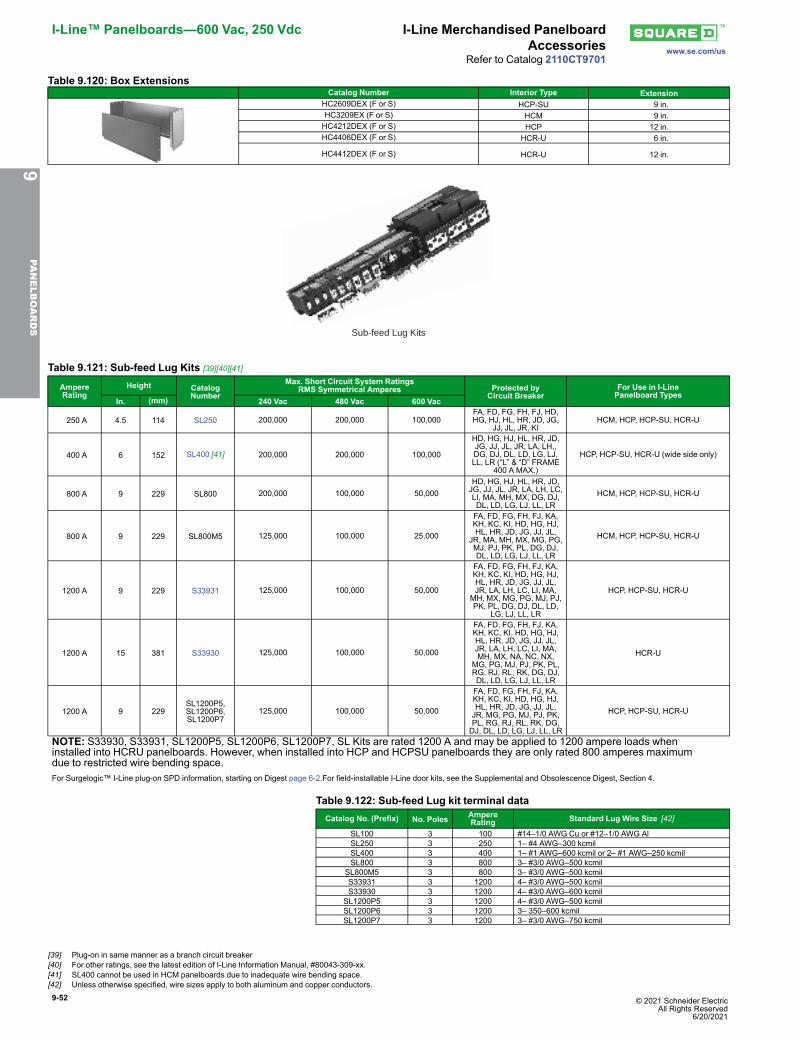
9-52 © 2021 Schneider Electric All Rights Reserved
6/20/2021
I-Line™ Panelboards—600 Vac, 250 Vdc I-Line Merchandised PanelboardAccessories www.se.com/us
Refer to Catalog 2110CT9701
Table 9.120: Box ExtensionsCatalog Number Interior Type Extension
HC2609DEX (F or S) HCP-SU 9 in.HC3209EX (F or S) HCM 9 in.HC4212DEX (F or S) HCP 12 in.HC4406DEX (F or S) HCR-U 6 in.
HC4412DEX (F or S) HCR-U 12 in.
Sub-feed Lug Kits
Table 9.121: Sub-feed Lug Kits [39][40][41]
AmpereRating
Height CatalogNumber
Max. Short Circuit System RatingsRMS Symmetrical Amperes Protected by
Circuit BreakerFor Use in I-LinePanelboard Types
In. (mm) 240 Vac 480 Vac 600 Vac
250 A 4.5 114 SL250 200,000 200,000 100,000FA, FD, FG, FH, FJ, HD,HG, HJ, HL, HR, JD, JG,
JJ, JL, JR, KIHCM, HCP, HCP-SU, HCR-U
400 A 6 152 SL400 [41] 200,000 200,000 100,000
HD, HG, HJ, HL, HR, JD,JG, JJ, JL, JR, LA, LH,,DG, DJ, DL, LD, LG, LJ,LL, LR (“L” & “D” FRAME
400 A MAX.)
HCP, HCP-SU, HCR-U (wide side only)
800 A 9 229 SL800 200,000 100,000 50,000HD, HG, HJ, HL, HR, JD,JG, JJ, JL, JR, LA, LH, LC,LI, MA, MH, MX, DG, DJ,DL, LD, LG, LJ, LL, LR
HCM, HCP, HCP-SU, HCR-U
800 A 9 229 SL800M5 125,000 100,000 25,000
FA, FD, FG, FH, FJ, KA,KH, KC, KI, HD, HG, HJ,HL, HR, JD, JG, JJ, JL,
JR, MA, MH, MX, MG, PG,MJ, PJ, PK, PL, DG, DJ,DL, LD, LG, LJ, LL, LR
HCM, HCP, HCP-SU, HCR-U
1200 A 9 229 S33931 125,000 100,000 50,000
FA, FD, FG, FH, FJ, KA,KH, KC, KI, HD, HG, HJ,HL, HR, JD, JG, JJ, JL,JR, LA, LH, LC, LI, MA,
MH, MX, MG, PG, MJ, PJ,PK, PL, DG, DJ, DL, LD,
LG, LJ, LL, LR
HCP, HCP-SU, HCR-U
1200 A 15 381 S33930 125,000 100,000 50,000
FA, FD, FG, FH, FJ, KA,KH, KC, KI, HD, HG, HJ,HL, HR, JD, JG, JJ, JL,JR, LA, LH, LC, LI, MA,MH, MX, NA, NC, NX,
MG, PG, MJ, PJ, PK, PL,RG, RJ, RL, RK, DG, DJ,DL, LD, LG, LJ, LL, LR
HCR-U
1200 A 9 229SL1200P5,SL1200P6,SL1200P7
125,000 100,000 50,000
FA, FD, FG, FH, FJ, KA,KH, KC, KI, HD, HG, HJ,HL, HR, JD, JG, JJ, JL,JR, MG, PG, MJ, PJ, PK,PL, RG, RJ, RL, RK, DG,DJ, DL, LD, LG, LJ, LL, LR
HCP, HCP-SU, HCR-U
NOTE: S33930, S33931, SL1200P5, SL1200P6, SL1200P7, SL Kits are rated 1200 A and may be applied to 1200 ampere loads wheninstalled into HCRU panelboards. However, when installed into HCP and HCPSU panelboards they are only rated 800 amperes maximumdue to restricted wire bending space.For Surgelogic™ I-Line plug-on SPD information, starting on Digest page 6-2.For field-installable I-Line door kits, see the Supplemental and Obsolescence Digest, Section 4.
Table 9.122: Sub-feed Lug kit terminal dataCatalog No. (Prefix) No. Poles Ampere
Rating Standard Lug Wire Size [42]
SL100 3 100 #14–1/0 AWG Cu or #12–1/0 AWG AlSL250 3 250 1– #4 AWG–300 kcmilSL400 3 400 1– #1 AWG–600 kcmil or 2– #1 AWG–250 kcmilSL800 3 800 3– #3/0 AWG–500 kcmil
SL800M5 3 800 3– #3/0 AWG–500 kcmilS33931 3 1200 4– #3/0 AWG–500 kcmilS33930 3 1200 4– #3/0 AWG–600 kcmil
SL1200P5 3 1200 4– #3/0 AWG–500 kcmilSL1200P6 3 1200 3– 350–600 kcmilSL1200P7 3 1200 3– #3/0 AWG–750 kcmil
9PA
NELBOARDS
[39] Plug-on in same manner as a branch circuit breaker[40] For other ratings, see the latest edition of I-Line Information Manual, #80043-309-xx.[41] SL400 cannot be used in HCM panelboards due to inadequate wire bending space.[42] Unless otherwise specified, wire sizes apply to both aluminum and copper conductors.
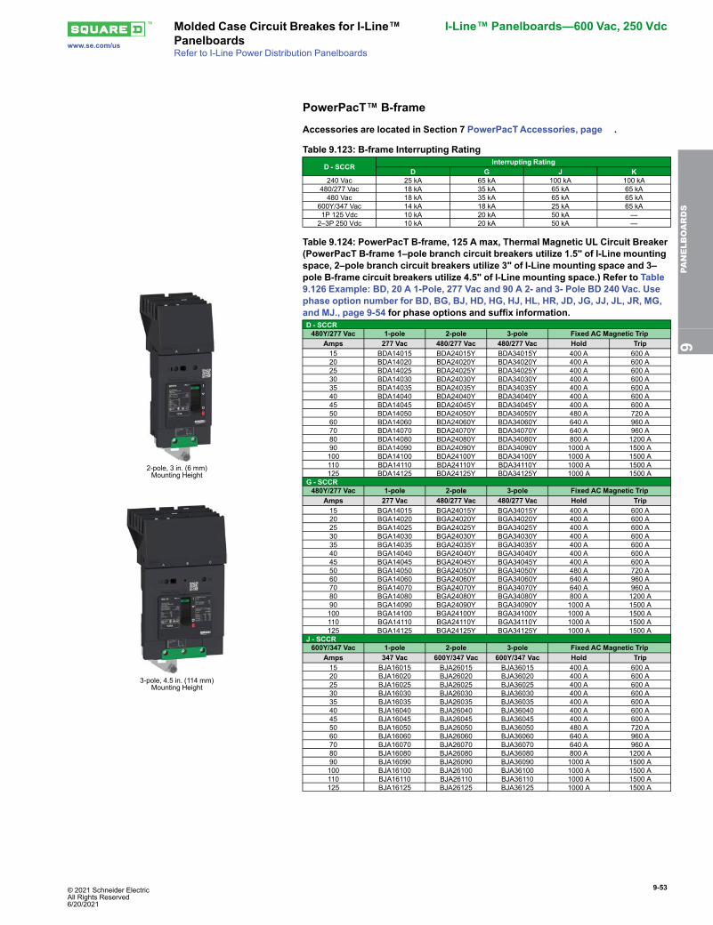
© 2021 Schneider Electric All Rights Reserved6/20/2021
9-53
www.se.com/us
Molded Case Circuit Breakes for I-Line™Panelboards
I-Line™ Panelboards—600 Vac, 250 Vdc
Refer to I-Line Power Distribution Panelboards
PowerPacT™ B-frame
Accessories are located in Section 7 PowerPacTAccessories, page .
Table 9.123: B-frame Interrupting Rating
D - SCCRInterrupting Rating
D G J K240 Vac 25 kA 65 kA 100 kA 100 kA
480/277 Vac 18 kA 35 kA 65 kA 65 kA480 Vac 18 kA 35 kA 65 kA 65 kA
600Y/347 Vac 14 kA 18 kA 25 kA 65 kA1P 125 Vdc 10 kA 20 kA 50 kA —2–3P 250 Vdc 10 kA 20 kA 50 kA —
2-pole, 3 in. (6 mm)Mounting Height
3-pole, 4.5 in. (114 mm)Mounting Height
Table 9.124: PowerPacT B-frame, 125 A max, Thermal Magnetic UL Circuit Breaker(PowerPacT B-frame 1–pole branch circuit breakers utilize 1.5" of I-Line mountingspace, 2–pole branch circuit breakers utilize 3" of I-Line mounting space and 3–pole B-frame circuit breakers utilize 4.5" of I-Line mounting space.) Refer to Table9.126 Example: BD, 20 A 1-Pole, 277 Vac and 90 A 2- and 3- Pole BD 240 Vac. Usephase option number for BD, BG, BJ, HD, HG, HJ, HL, HR, JD, JG, JJ, JL, JR, MG,and MJ., page 9-54 for phase options and suffix information.D - SCCR480Y/277 Vac 1-pole 2-pole 3-pole Fixed AC Magnetic Trip
Amps 277 Vac 480/277 Vac 480/277 Vac Hold Trip15 BDA14015 BDA24015Y BDA34015Y 400 A 600 A20 BDA14020 BDA24020Y BDA34020Y 400 A 600 A25 BDA14025 BDA24025Y BDA34025Y 400 A 600 A30 BDA14030 BDA24030Y BDA34030Y 400 A 600 A35 BDA14035 BDA24035Y BDA34035Y 400 A 600 A40 BDA14040 BDA24040Y BDA34040Y 400 A 600 A45 BDA14045 BDA24045Y BDA34045Y 400 A 600 A50 BDA14050 BDA24050Y BDA34050Y 480 A 720 A60 BDA14060 BDA24060Y BDA34060Y 640 A 960 A70 BDA14070 BDA24070Y BDA34070Y 640 A 960 A80 BDA14080 BDA24080Y BDA34080Y 800 A 1200 A90 BDA14090 BDA24090Y BDA34090Y 1000 A 1500 A100 BDA14100 BDA24100Y BDA34100Y 1000 A 1500 A110 BDA14110 BDA24110Y BDA34110Y 1000 A 1500 A125 BDA14125 BDA24125Y BDA34125Y 1000 A 1500 A
G - SCCR480Y/277 Vac 1-pole 2-pole 3-pole Fixed AC Magnetic Trip
Amps 277 Vac 480/277 Vac 480/277 Vac Hold Trip15 BGA14015 BGA24015Y BGA34015Y 400 A 600 A20 BGA14020 BGA24020Y BGA34020Y 400 A 600 A25 BGA14025 BGA24025Y BGA34025Y 400 A 600 A30 BGA14030 BGA24030Y BGA34030Y 400 A 600 A35 BGA14035 BGA24035Y BGA34035Y 400 A 600 A40 BGA14040 BGA24040Y BGA34040Y 400 A 600 A45 BGA14045 BGA24045Y BGA34045Y 400 A 600 A50 BGA14050 BGA24050Y BGA34050Y 480 A 720 A60 BGA14060 BGA24060Y BGA34060Y 640 A 960 A70 BGA14070 BGA24070Y BGA34070Y 640 A 960 A80 BGA14080 BGA24080Y BGA34080Y 800 A 1200 A90 BGA14090 BGA24090Y BGA34090Y 1000 A 1500 A100 BGA14100 BGA24100Y BGA34100Y 1000 A 1500 A110 BGA14110 BGA24110Y BGA34110Y 1000 A 1500 A125 BGA14125 BGA24125Y BGA34125Y 1000 A 1500 A
J - SCCR600Y/347 Vac 1-pole 2-pole 3-pole Fixed AC Magnetic Trip
Amps 347 Vac 600Y/347 Vac 600Y/347 Vac Hold Trip15 BJA16015 BJA26015 BJA36015 400 A 600 A20 BJA16020 BJA26020 BJA36020 400 A 600 A25 BJA16025 BJA26025 BJA36025 400 A 600 A30 BJA16030 BJA26030 BJA36030 400 A 600 A35 BJA16035 BJA26035 BJA36035 400 A 600 A40 BJA16040 BJA26040 BJA36040 400 A 600 A45 BJA16045 BJA26045 BJA36045 400 A 600 A50 BJA16050 BJA26050 BJA36050 480 A 720 A60 BJA16060 BJA26060 BJA36060 640 A 960 A70 BJA16070 BJA26070 BJA36070 640 A 960 A80 BJA16080 BJA26080 BJA36080 800 A 1200 A90 BJA16090 BJA26090 BJA36090 1000 A 1500 A100 BJA16100 BJA26100 BJA36100 1000 A 1500 A110 BJA16110 BJA26110 BJA36110 1000 A 1500 A125 BJA16125 BJA26125 BJA36125 1000 A 1500 A
9PA
NELBOARDS
9-54 © 2021 Schneider Electric All Rights Reserved
6/20/2021
I-Line™ Panelboards—600 Vac, 250 Vdc Molded Case Circuit Breakes for I-Line™Panelboards www.se.com/us
Refer to I-Line Power Distribution Panelboards
I-Line HQO Accessory
For phase option information see Table 9.126.
Table 9.125: QO™ Distribution Panel—240 Vac Max. Only Mounts in Type HCM,HCP, HCP-SU, or HCR-U I-Line panelboards, 30 A max. branch circuit breaker.
Maximum No. 1-poleQO Circuit Breakers
PhaseConnection
Mounting Height 2-poleCatalog Number
3-poleCatalog NumberIn. mm
6 AB 4.5 114 HQO206AB —6 BC 4.5 114 HQO206BC —6 AC 4.5 114 HQO206AC —6 ABC 4.5 114 — HQO3066 CBA 4.5 114 — HQO306CBA
Table 9.126: Example: BD, 20 A 1-Pole, 277 Vac and 90 A 2- and 3- Pole BD 240 Vac.Use phase option number for BD, BG, BJ, HD, HG, HJ, HL, HR, JD, JG, JJ, JL, JR,MG, and MJ.
PhaseOptionNumber
PhaseConnection 1-pole 2-pole 3-pole
1 A FJA140201 — —3 B FJA140203 — —5 C FJA140205 — —1 AB — QBA220701 —2 AC — QBA220702 —3 BA — QBA220703 —4 BC — QBA220704 —5 CA — QBA220705 —6 CB — QBA220706 —
Standard [43] ABC — — QBA320706 CBA — — QBA320706
9PA
NELBOARDS
[43] The absence of a phase option number after a 3-pole catalog number will result in an ABC phase connection.
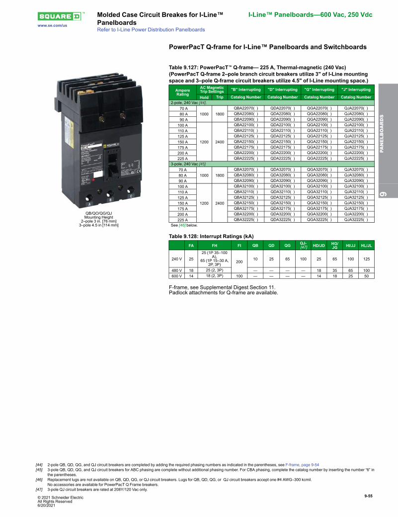
© 2021 Schneider Electric All Rights Reserved6/20/2021
9-55
www.se.com/us
Molded Case Circuit Breakes for I-Line™Panelboards
I-Line™ Panelboards—600 Vac, 250 Vdc
Refer to I-Line Power Distribution Panelboards
PowerPacT Q-frame for I-Line™ Panelboards and Switchboards
QB/QO/QG/QJMounting Height
2–pole 3 in. [76 mm]3–pole 4.5 in [114 mm]
Table 9.127: PowerPacT™ Q-frame— 225 A, Thermal-magnetic (240 Vac)(PowerPacT Q-frame 2–pole branch circuit breakers utilize 3" of I-Line mountingspace and 3–pole Q-frame circuit breakers utilize 4.5" of I-Line mounting space.)
AmpereRating
AC MagneticTrip Settings "B" Interrupting "D" Interrupting "G" Interrupting "J" Interrupting
Hold Trip Catalog Number Catalog Number Catalog Number Catalog Number2-pole, 240 Vac [44].
70 A1000 1800
QBA22070( ) QDA22070( ) QGA22070( ) QJA22070( ) 80 A QBA22080( ) QDA22080( ) QGA22080( ) QJA22080( ) 90 A QBA22090( ) QDA22090( ) QGA22090( ) QJA22090( )100 A
1200 2400
QBA22100( ) QDA22100( ) QGA22100( ) QJA22100( )110 A QBA22110( ) QDA22110( ) QGA22110( ) QJA22110( )125 A QBA22125( ) QDA22125( ) QGA22125( ) QJA22125( )150 A QBA22150( ) QDA22150( ) QGA22150( ) QJA22150( )175 A QBA22175( ) QDA22175( ) QGA22175( ) QJA22175( )200 A QBA22200( ) QDA22200( ) QGA22200( ) QJA22200( )225 A QBA22225( ) QDA22225( ) QGA22225( ) QJA22225( )
3-pole, 240 Vac [45]70 A
1000 1800QBA32070( ) QDA32070( ) QGA32070( ) QJA32070( )
80 A QBA32080( ) QDA32080( ) QGA32080( ) QJA32080( )90 A QBA32090( ) QDA32090( ) QGA32090( ) QJA32090( )100 A
1200 2400
QBA32100( ) QDA32100( ) QGA32100( ) QJA32100( )110 A QBA32110( ) QDA32110( ) QGA32110( ) QJA32110( )125 A QBA32125( ) QDA32125( ) QGA32125( ) QJA32125( )150 A QBA32150( ) QDA32150( ) QGA32150( ) QJA32150( )175 A QBA32175( ) QDA32175( ) QGA32175( ) QJA32175( )200 A QBA32200( ) QDA32200( ) QGA32200( ) QJA32200( )225 A QBA32225( ) QDA32225( ) QGA32225( ) QJA32225( )
See [46] below.
Table 9.128: Interrupt Ratings (kA)FA FH FI QB QD QG QJ-
[47] HD/JD HG/JG HI/JJ HL/JL
240 V 2525 (1P 35–100
A),65 (1P 15–30 A,
2P, 3P)200
10 25 65 100 25 65 100 125
480 V 18 25 (2, 3P) — — — — 18 35 65 100600 V 14 18 (2, 3P) 100 — — — — 14 18 25 50
F-frame, see Supplemental Digest Section 11.Padlock attachments for Q-frame are available.
9PA
NELBOARDS
[44] 2-pole QB, QD, QG, and QJ circuit breakers are completed by adding the required phasing numbers as indicated in the parentheses, see F-frame, page 9-54[45] 3-pole QB, QD, QG, and QJ circuit breakers for ABC phasing are complete without additional phasing number. For CBA phasing, complete the catalog number by inserting the number “6” in
the parentheses.[46] Replacement lugs are not available on QB, QD, QG, or QJ circuit breakers. Lugs for QB, QD, QG, or QJ circuit breakers accept one #4 AWG–300 kcmil.
No accessories are available for PowerPacT Q Frame breakers.[47] 3-pole QJ circuit breakers are rated at 208Y/120 Vac only.
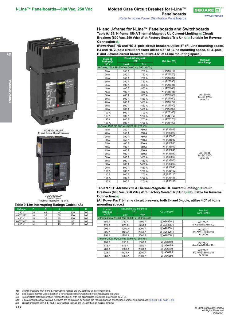
9-56 © 2021 Schneider Electric All Rights Reserved
6/20/2021
I-Line™ Panelboards—600 Vac, 250 Vdc Molded Case Circuit Breakes for I-Line™Panelboards www.se.com/us
Refer to I-Line Power Distribution Panelboards
H- and J-frame for I-Line™ Panelboards and Switchboards
HD/HG/HJ/HL/HR2- and 3-pole Circuit Breaker
JD/JG/JJ/JL/JR2- and 3-pole
Thermal-Magnetic Trip Unit
Table 9.129: H-frame 150 AThermal-Magnetic UL Current-Limiting[48] CircuitBreakers (600 Vac, 250 Vdc) With Factory Sealed Trip Unit[49] Suitable for ReverseConnection[49](PowerPacT HD and HG 2–pole circuit breakers utilize 3" of I-Line mounting space,HJ and HL 2–pole circuit breakers utilize 4.5" of I-Line mounting space, all 3–poleH and J-frame circuit breakers utilize 4.5" of I-Line mounting space.)
CurrentRating @40o C
Fixed AC MagneticTrip Cat. No. [50] Terminal
Wire RangeHold Trip
H-frame, 150A 2P, 600 Vac 50/60 Hz, 250 Vdc[51]15 A 350 A 750 A H( )A26015( )
AL150HD14–3/0 AWGAl or Cu
20 A 350 A 750 A H( )A26020( )25 A 350 A 750 A H( )A26025( )30 A 350 A 750 A H( )A26030( )35 A 400 A 850 A H( )A26035( )40 A 400 A 850 A H( )A26040( )45 A 400 A 850 A H( )A26045( )50 A 400 A 850 A H( )A26050( )60 A 800 A 1450 A H( )A26060( )70 A 800 A 1450 A H( )A26070( )80 A 800 A 1450 A H( )A26080( )90 A 800 A 1450 A H( )A26090( )100 A 800 A 1700 A H( )A26100( )110 A 900 A 1700 A H( )A26110( )125 A 900 A 1700 A H( )A26125( )150 A 900 A 1700 A H( )A26150( )
H-frame 150A 3P, 600 Vac 50/60 Hz, 250 Vdc15 A 350 A 750 A H( )A36015
AL150HD14–3/0 AWGAl or Cu
20 A 350 A 750 A H( )A3602025 A 350 A 750 A H( )A3602530 A 350 A 750 A H( )A3603035 A 400 A 850 A H( )A3603540 A 400 A 850 A H( )A3604045 A 400 A 850 A H( )A3604550 A 400 A 850 A H( )A3605060 A 800 A 1450 A H( )A3606070 A 800 A 1450 A H( )A3607080 A 800 A 1450 A H( )A3608090 A 800 A 1450 A H( )A36090100 A 800 A 1700 A H( )A36100110 A 900 A 1700 A H( )A36110125 A 900 A 1700 A H( )A36125150 A 900 A 1700 A H( )A36150
Table 9.130: Interrupting Ratings Codes (kA)Voltage D G J L R240 V 25 65 100 125 200
480Y/277 18 35 65 100 200480 V 18 35 65 100 200
600Y/347 14 18 25 50 100600 V 14 18 25 50 100
Table 9.131: J-frame 250 AThermal-Magnetic UL Current-Limiting[52]CircuitBreakers (600 Vac, 250 Vdc) With Factory Sealed Trip Unit[49] Suitable for ReverseConnection[49](All PowerPacT J-frame circuit breakers, both 2– and 3–pole, utilize 4.5" of I-Linemounting space.)
CurrentRating @40oC
Adjustable AC MagneticTrip Cat. No.[50] Terminal
Wire RangeLow High
J-frame 250A 2P, 600 Vac 50/60 Hz, 250 Vdc[51]150 A 750 A 1500 A J( )A26150( ) AL175JD
4–4/0 AWG Al or Cu175 A 875 A 1750 A J( )A26175( )200 A 1000 A 2000 A J( )A26200( ) AL250JD
3/0 AWG–350 kcmilAl or Cu
225 A 1125 A 2250 A J( )A26225( )250 A 1250 A 2500 A J( )A26250( )
J-frame 250A 3P, 600 Vac 50/60 Hz, 250 Vdc150 A 750 A 1500 A J( )A36150 AL175JD
4–4/0 AWG Al or Cu175 A 875 A 1750 A J( )A36175200 A 1000 A 2000 A J( )A36200 AL250JD
3/0 AWG–350 kcmilAl or Cu
225 A 1125 A 2250 A J( )A36225250 A 1250 A 2500 A J( )A36250
9PA
NELBOARDS
[48] Circuit breakers with J and L interrupting ratings are UL certified as current limiting.[49] See Supplemental Digest Section 3 for circuit breakers with field-interchangeable trip units.[50] To complete catalog number, replace the blank with the appropriate interrupting rating (D, G, J, L).[51] 2 pole circuit breaker catalog numbers are completed by adding the required phase connection number as a suffix see Table 9.128, page 9-58.[52] Circuit breakers with J, L, and R interrupting ratings are UL certified as current limiting.
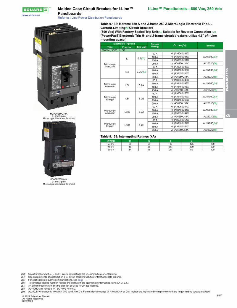
© 2021 Schneider Electric All Rights Reserved6/20/2021
9-57
www.se.com/us
Molded Case Circuit Breakes for I-Line™Panelboards
I-Line™ Panelboards—600 Vac, 250 Vdc
Refer to I-Line Power Distribution Panelboards
HDA36250U33X2- and 3-pole
MicroLogic Electronic Trip Unit
JDA36250U44X2- and 3-pole
MicroLogic Electronic Trip Unit
Table 9.132: H-frame 150 A and J-frame 250 A MicroLogic Electronic Trip ULCurrent-Limiting[53]Circuit Breakers(600 Vac) With Factory Sealed Trip Unit[54] Suitable for Reverse Connection [55]
(PowerPacT Electronic Trip H- and J-frame circuit breakers utilize 4.5" of I-Linemounting space.)
Electronic Trip Unit SensorRating Cat. No.[56] TerminalType Function Trip Unit
600 Vac, 50/60 Hz, 3P
MicroLogicStandard
LI 3.2[57]
60 A H( )A36060U31XAL150HD[58]100 A H( )A36100U31X
150 A H( )A36150U31X250 A J( )A36250U31X AL250JD[59]
LSI 3.2S[57]
60 A H( )A36060U33XAL150HD[58]100 A H( )A36100U33X
150 A H( )A36150U33X250 A J( )A36250U33X AL250JD[59]
MicroLogicAmmeter LSI 5.2A
60 A H( )A36060U43XAL150HD[58]100 A H( )A36100U43X
150 A H( )A36150U43X250 A J( )A36250U43X AL250JD[59]
MicroLogicEnergy LSI 5.2E
60 A H( )A36060U53XAL150HD[58]100 A H( )A36100U53X
150 A H( )A36150U53X250 A J( )A36250U53X AL250JD[59]
MicroLogicAmmeter LSIG 6.2A
60 A H( )A36060U44XAL150HD[58]100 A H( )A36100U44X
150 A H( )A36150U44X250 A J( )A36250U44X AL250JD[59]
MicroLogicEnergy LSIG 6.2E
60 A H( )A36060U54XAL150HD[58]100 A H( )A36100U54X
150 A H( )A36150U54X250 A J( )A36250U54X AL250JD[59]
Table 9.133: Interrupting Ratings (kA)Voltage D G J L R240 V 25 65 100 125 200480 V 18 35 65 100 200600 V 14 18 25 50 100
9PA
NELBOARDS
[53] Circuit breakers with J, L, and R interrupting ratings are UL certified as current limiting.[54] See Supplemental Digest Section 3 for circuit breakers with field-interchangeable trip units.[55] For applications requiring communications, see page .[56] To complete catalog number, replace the blank with the appropriate interrupting rating (D, G, J, L).[57] 3P circuit breakers with this trip unit can be used for 2P applications.[58] AL150HD wire range is 14–3/0 AWG Al or Cu.[59] AL250JD wire range is 3/0 AWG–350 kcmil Al or Cu. For smaller wire range (4–4/0 AWG Al or Cu), replace the lug’s wire binding screws with the larger binding screws provided.
9-58 © 2021 Schneider Electric All Rights Reserved
6/20/2021
I-Line™ Panelboards—600 Vac, 250 Vdc Molded Case Circuit Breakes for I-Line™Panelboards www.se.com/us
Refer to I-Line Power Distribution Panelboards
J-frame Mission Critical Circuit BreakerTable 9.134: J-frame 250 A MicroLogic Electronic Trip Mission Critical Circuit Breakers (480/277 Vac) With Factory Sealted Trip UnitsSuitable for Reverse Connection[60]
Electronic TripUnit Type
TripFunction Trip Unit Continuous
CurrentD Interrupting G Interrupting J Interrupting L Interrupting
TerminalCat. No. Cat. No. Cat. No. Cat. No.
Standard LI 3.2 W 250 JDA34250WU31X JGA34250WU31X JJA34250WU31X JLA34250WU31X AL250JD[61]Standard LSI 3.2S-W 250 JDA34250WU33X JGA34250WU33X JJA34250WU33X JLA34250WU33X AL250JD[61]
High Perf. Ammerter LSI 5.2A-W 250 JDA34250WU43X JGA34250WU43X JJA34250WU43X JLA34250WU43X AL250JD[61]High Perf. Energy LSI 5.2E-W 250 JDA34250WU53X JGA34250WU53X JJA34250WU53X JLA34250WU53X AL250JD[61]High perf. Ammerter LSIG 6.2A-W 250 JDA34250WU44X JGA34250WU44X JJA34250WU44X JLA34250WU44X AL250JD[61]High Perf. Energy LSIG 6.2E-W 250 JDA34250WU54X JGA34250WU54X JJA34250WU54X JLA34250WU54X AL250JD[61]
L-frame Mission Critical Circuit BreakerTable 9.135: L-frame 600 A MicroLogic Electronic Trip Mission Critical Circuit Breakers (480/277 Vac) With Factory Sealed Trip UnitsSuitable for Reverse Connection[60]
Electronic TripUnit Type
TripFunction Trip Unit Continuous
CurrentD Interrupting G Interrupting J Interrupting L Interrupting
TerminalCat. No. Cat. No. Cat. No. Cat. No.
Standard LI 3.3 W250 LDA34250WU31X LGA34250WU31X LJA34250WU31X LLA34250WU31X AL400L61K3[62]400 LDA34400WU31X LGA34400WU31X LJA34400WU31X LLA34400WU31X AL600LF52K3[63]600 LDA34600WU31X LGA34600WU31X LJA34600WU31X LLA34600WU31X
Standard LSI 3.3S-W250 LDA34250WU33X LGA34250WU33X LJA34250WU33X LLA34250WU33X AL400L61K3[62]400 LDA34400WU33X LGA34400WU33X LJA34400WU33X LLA34400WU33X AL600LF52K3[63]600 LDA34600WU33X LGA34600WU33X LJA34600WU33X LLA34600WU33X
High Perf. Ammeter LSI 5.3A-W 400 LDA34400WU43X LGA34400WU43X LJA34400WU43X LLA34400WU43X AL600LF52K3[63]600 LDA34600WU43X LGA34600WU43X LJA34600WU43X LLA34600WU43X
High Perf. Energy LSI 5.3E-W 400 LDA34400WU53X LGA34400WU53X LJA34400WU53X LLA34400WU53X AL600LF52K3[63]600 LDA34600WU53X LGA34600WU53X LJA34600WU53X LLA34600WU53X
High Perf. Ammeter LSIG 6.3A-W 400 LDA34400WU44X LGA34400WU44X LJA34400WU44X LLA34400WU44X AL600LF52K3[63]600 LDA34600WU44X LGA34600WU44X LJA34600WU44X LLA34600WU44X
High Perf. Energy LSIG 6.3E-W 400 LDA34400WU54X LGA34400WU54X LJA34400WU54X LLA34400WU54X AL600LF52K3[63]600 LDA34600WU54X LGA34600WU54X LJA34600WU54X LLA34600WU54X
Table 9.136: PowerPacT™ H-, J-, and L-frame Automatic Molded Case Switches, 600 VacCircuitBreaker Poles Ampere
RatingG Withstand LWithstand R Withstand
Terminal Wire RangeCat. No. Trip
Point Cat. No. Trip Point Cat. No. Trip Point
H-frameJ-frame
2[64]150 A HGA26000S15( ) 2250 A HLA26000S15 2250 A — — — —175 A JGA26000S17( ) 3125 A JLA26000S17 3125 A — — — —250 A JGA26000S25( ) 3125 A JLA26000S25 3125 A — — — —
3150 A HGA36000S15 2250 A HLA36000S15 2250 A HRA36000S15 2250 A AL150HD 14 AWG–3/0 AWG Al/Cu175 A JGA36000S17 3125 A JLA36000S17 3125 A JRA36000S17 3125 A AL175JD 4–4/0 AWG Al/Cu250 A JGA36000S25 3125 A JLA36000S25 3125 A JRA36000S25 3125 A AL250JD 3/0 AWG–350 kcmil Al/Cu
L-frame 3 400 A LGA36000S40X 4800 A LLA36000S40X 4800 A LRA36000S40X 4800 A AL150HD AL600LS52K3(2) 2/0 AWG–500 kcmil Al/Cu600 A LGA36000S60X 6600 A LLA36000S60X 6600 A LRA36000S60X 6600 A AL250JD
K-frame accessories starting on Supplemental Digest Section 3.K-frame dimensions Supplemental Digest Section 3.K-frame optional lugs Supplemental Digest Section 3.H-, J-, and L-frame accessories starting on PowerPacTAccessories, page .H-, J-, and L-frame dimensions starting on Molded Case Circuit Breaker Dimensions, page .H-, J-, and L-frame optional lugs Mechanical Lugs, page .
Table 9.137: Interrupting Ratings Codes (kA)Voltage D G J L R240 V 25 65 100 125 200
480Y/277 18 35 65 100 200480 V 18 35 65 100 200
600Y/347 14 18 25 50 100600 V 14 18 25 50 100
Table 9.138: Phase Options—Example HDA26150( )Phase Option
NumberPhase
Connection 2-pole 3-pole
1 AB HDA261501 —2 AC HDA261502 —3 BA HDA261503 —4 BC HDA261504 —5 CA HDA261505 —6 CB HDA261506 —
Standard ABC — JDA34250WU31X6 CBA — JDA34250WU31X6
9PA
NELBOARDS
[60] Standard rated (80%). Not available in 100% rated.[61] AL250JD terminal wire range is (1) 3/0 AWG–350 kcmil Al or Cu.[62] AL400L61K3 terminal wire range is (1) #2 AWG–500 kcmil Al or #2 AWG–600 kcmil Cu..[63] AL600LF52K3 terminal wire range is (2) #3/0 AWG–500 kcmil Al or Cu.[64] 2-pole circuit breaker catalog numbers are completed by adding the required phase connection number as a suffix, see Table 9.128, page 9-58.
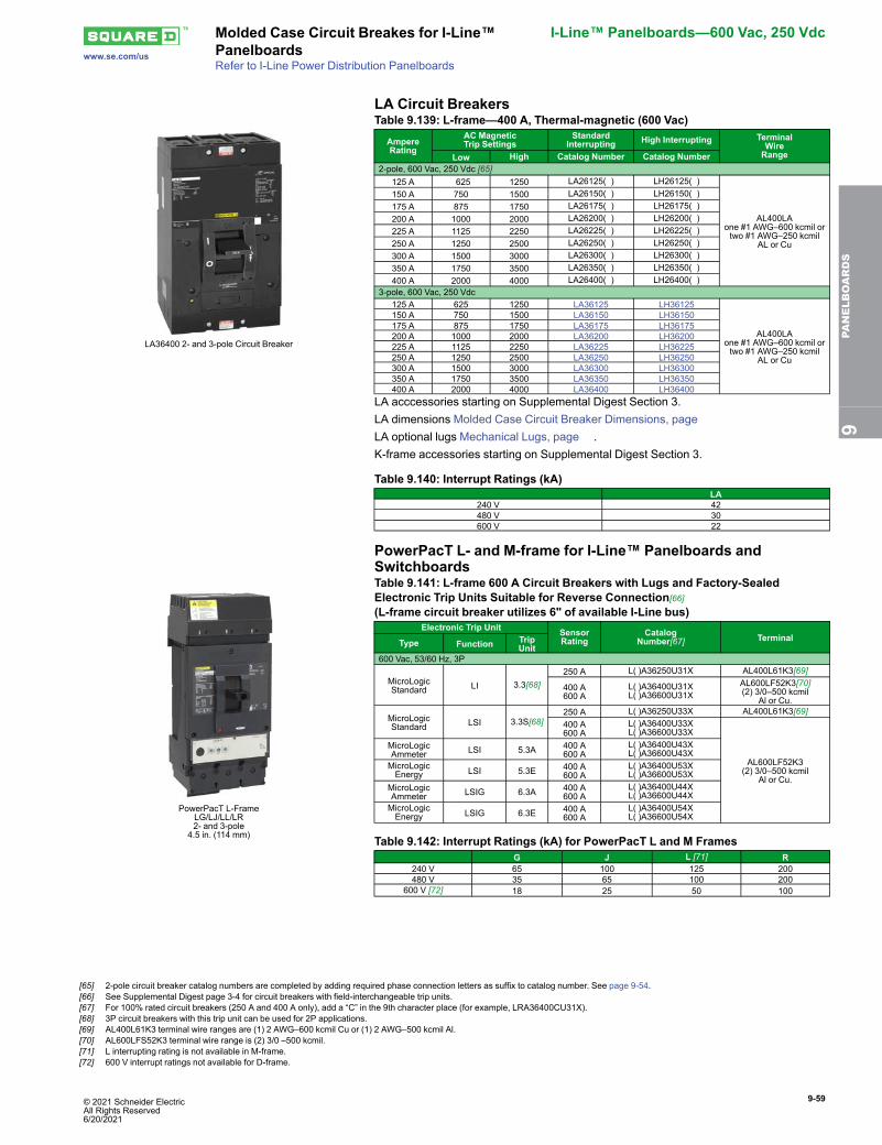
© 2021 Schneider Electric All Rights Reserved6/20/2021
9-59
www.se.com/us
Molded Case Circuit Breakes for I-Line™Panelboards
I-Line™ Panelboards—600 Vac, 250 Vdc
Refer to I-Line Power Distribution Panelboards
LA Circuit Breakers
LA36400 2- and 3-pole Circuit Breaker
Table 9.139: L-frame—400 A, Thermal-magnetic (600 Vac)
AmpereRating
AC MagneticTrip Settings
StandardInterrupting High Interrupting Terminal
WireRangeLow High Catalog Number Catalog Number
2-pole, 600 Vac, 250 Vdc [65]125 A 625 1250 LA26125( ) LH26125( )
AL400LAone #1 AWG–600 kcmil ortwo #1 AWG–250 kcmil
AL or Cu
150 A 750 1500 LA26150( ) LH26150( )175 A 875 1750 LA26175( ) LH26175( )200 A 1000 2000 LA26200( ) LH26200( )225 A 1125 2250 LA26225( ) LH26225( )250 A 1250 2500 LA26250( ) LH26250( )300 A 1500 3000 LA26300( ) LH26300( )350 A 1750 3500 LA26350( ) LH26350( )400 A 2000 4000 LA26400( ) LH26400( )
3-pole, 600 Vac, 250 Vdc125 A 625 1250 LA36125 LH36125
AL400LAone #1 AWG–600 kcmil ortwo #1 AWG–250 kcmil
AL or Cu
150 A 750 1500 LA36150 LH36150175 A 875 1750 LA36175 LH36175200 A 1000 2000 LA36200 LH36200225 A 1125 2250 LA36225 LH36225250 A 1250 2500 LA36250 LH36250300 A 1500 3000 LA36300 LH36300350 A 1750 3500 LA36350 LH36350400 A 2000 4000 LA36400 LH36400
LA acccessories starting on Supplemental Digest Section 3.LA dimensions Molded Case Circuit Breaker Dimensions, pageLA optional lugs Mechanical Lugs, page .K-frame accessories starting on Supplemental Digest Section 3.
Table 9.140: Interrupt Ratings (kA)LA
240 V 42480 V 30600 V 22
PowerPacT L- and M-frame for I-Line™ Panelboards andSwitchboards
PowerPacT L-FrameLG/LJ/LL/LR2- and 3-pole
4.5 in. (114 mm)
Table 9.141: L-frame 600 A Circuit Breakers with Lugs and Factory-SealedElectronic Trip Units Suitable for Reverse Connection[66](L-frame circuit breaker utilizes 6" of available I-Line bus)
Electronic Trip Unit SensorRating
CatalogNumber[67] TerminalType Function Trip
Unit600 Vac, 53/60 Hz, 3P
MicroLogicStandard LI 3.3[68]
250 A L( )A36250U31X AL400L61K3[69]
400 A600 A
L( )A36400U31XL( )A36600U31X
AL600LF52K3[70](2) 3/0–500 kcmil
Al or Cu.
MicroLogicStandard LSI 3.3S[68]
250 A L( )A36250U33X AL400L61K3[69]400 A600 A
L( )A36400U33XL( )A36600U33X
AL600LF52K3(2) 3/0–500 kcmil
Al or Cu.
MicroLogicAmmeter LSI 5.3A 400 A
600 AL( )A36400U43XL( )A36600U43X
MicroLogicEnergy LSI 5.3E 400 A
600 AL( )A36400U53XL( )A36600U53X
MicroLogicAmmeter LSIG 6.3A 400 A
600 AL( )A36400U44XL( )A36600U44X
MicroLogicEnergy LSIG 6.3E 400 A
600 AL( )A36400U54XL( )A36600U54X
Table 9.142: Interrupt Ratings (kA) for PowerPacT L and M FramesG J L [71] R
240 V 65 100 125 200480 V 35 65 100 200
600 V [72] 18 25 50 100
9PA
NELBOARDS
[65] 2-pole circuit breaker catalog numbers are completed by adding required phase connection letters as suffix to catalog number. See page 9-54.[66] See Supplemental Digest page 3-4 for circuit breakers with field-interchangeable trip units.[67] For 100% rated circuit breakers (250 A and 400 A only), add a “C” in the 9th character place (for example, LRA36400CU31X).[68] 3P circuit breakers with this trip unit can be used for 2P applications.[69] AL400L61K3 terminal wire ranges are (1) 2 AWG–600 kcmil Cu or (1) 2 AWG–500 kcmil Al.[70] AL600LFS52K3 terminal wire range is (2) 3/0 –500 kcmil.[71] L interrupting rating is not available in M-frame.[72] 600 V interrupt ratings not available for D-frame.
9-60 © 2021 Schneider Electric All Rights Reserved
6/20/2021
I-Line™ Panelboards—600 Vac, 250 Vdc Molded Case Circuit Breakes for I-Line™Panelboards www.se.com/us
Refer to I-Line Power Distribution Panelboards
Table 9.143: PowerPacT M-frame: with ET1.0 Factory – sealed trip unit (not field adjustable)—800 A [73]
(PowerPacT M-frame circuit breakers utilize 9" of the available I-Line bussing.)
AmpereRating
Adjustable InstantaneousTrip Range [74] G Interrupting J Interrupting Terminal
Wire RangeLow High Catalog Number [75] Catalog Number [75]
2-pole, 600 Vac,50/60 Hz
300 A 600 3000 MGA26300( ) MJA26300( )
3–3/0through 500 kcmil
Al or Cu
350 A 700 3500 MGA26350( ) MJA26350( )400 A 800 4000 MGA26400( ) MJA26400( )450 A 900 4500 MGA26450( ) MJA26450( )500 A 1000 5000 MGA26500( ) MJA26500( )600 A 1200 6000 MGA26600( ) MJA26600( )700 A 1400 7000 MGA26700( ) MJA26700( )800 A 1600 8000 MGA26800( ) MJA26800( )
3-pole, 600 Vac,50/60 Hz
300 A 600 3000 MGA36300 MJA36300
3–3/0through 500 kcmil
Al or Cu
350 A 700 3500 MGA36350 MJA36350400 A 800 4000 MGA36400 MJA36400450 A 900 4500 MGA36450 MJA36450500 A 1000 5000 MGA36500 MJA36500600 A 1200 6000 MGA36600 MJA36600700 A 1400 7000 MGA36700 MJA36700800 A 1600 8000 MGA36800 MJA36800
L-frame accessories, see Supplemental Digest Section 3.L-frame dimensions, page .L-frame optional lugs, page .
M-frame accessories, page .M-frame dimensions, page .M-frame optional lugs, page .
Table 9.144: Automatic Molded Case Switches—600 Vac, 50/60 HzAmpereRating
2-pole 3-pole Withstand Rating [76] Trip Point Amperes TerminalWire RangeCatalog Number [77] Catalog Number 240 Vac 480 Vac 600 Vac AC
600 A PJA26000S60( ) PJA36000S60 100 65 25 10000 3–3/0 through500 kcmil Al or Cu800 A PJA26000S80( ) PJA36000S80 100 65 25 10000
1000 A PJA26000S10( ) PJA36000S10 100 65 25 10000 4–3/0 through500 kcmil Al or Cu1200 A PJA26000S12( ) PJA36000S12 100 65 25 10000
9PA
NELBOARDS
[73] The ET 1.0 trip unit cannot be field replaced, nor does it allow adjustment of the long-time trip point setting. It is considered an electronic equivalent of a thermal-magnet circuit breaker.[74] UL magnetic trip setting tolerances are ±10% from the nominal values shown.[75] Fill in parentheses with the following phase connection options: (2) for AC and (5) for CA.[76] The withstand rating is the fault current, at rated voltage, that the molded case switch will withstand without damage when protected by a circuit breaker with an equal ampere rating.[77] Fill in parentheses with the following phase connection options: (2) for AC or (5) for CA.
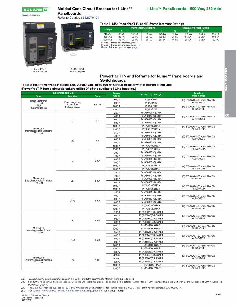
© 2021 Schneider Electric All Rights Reserved6/20/2021
9-61
www.se.com/us
Molded Case Circuit Breakes for I-Line™Panelboards
I-Line™ Panelboards—600 Vac, 250 Vdc
Refer to Catalog 0612CT0101
PG/PJ/PK/PL2– and 3–pole
RG/RJ/RK/RL2– and 3–pole
Table 9.145: PowerPacT P- and R-frame Interrupt RatingsVoltage P-frame Interrupt Rating R-frame Interrupt Rating
G J K L G J K L240 Vac 65 kA 100 kA 65 kA 125 kA 65 kA 100 kA 65 kA 125 kA480 Vac 35 kA 65 kA 50 kA 100 kA 35 kA 65 kA 65 kA 100 kA600 Vac 18 kA 25 kA 50 kA 25 kA 18 kA 25 kA 65 kA 50 kA
P- and R-frame accessories, page .P- and R-frame dimensions, page .P- and R-frame optional lugs, page .
PowerPacT P- and R-frame for I-Line™ Panelboards andSwitchboards
Table 9.146: PowerPacT P-frame 1200 A (600 Vac, 50/60 Hz) 3P Circuit Breaker with Electronic Trip Unit(PowerPacT P-frame circuit breakers utilize 9" of the available I-Line bussing.)
Electronic Trip Unit SensorRating Cat. No.[78][79][80][81] Terminal
Wire RangeType Function Code
Basic ElectronicTrip Unit(Not
Interchangeable)
Fixed long-time,Adjustable
InstantaneousET1.0I
600 A P( )A36060 (3) 3/0 AWG–500 kcmil Al or CuAL800M23K 800 A P( )A36080
1000 A P( )A36100 (4) 3/0 AWG–500 kcmil Al or CuAL1200P24K1200 A P( )A36120
MicroLogicInterchangeable Standard
Trip Unit
LI 3.0
250 A P( )A36025(C)U31A
(3) 3/0 AWG–500 kcmil Al or CuAL800M23K
400 A P( )A36040(C)U31A 600 A P( )A36060(C)U31A 800 A P( )A36080(C)U31A1000 A P( )A36100U31A (4) 3/0 AWG–500 kcmil Al or Cu
AL1200P24K1200 A P( )A36120U31A
LSI 5.0
250 A P( )A36025(C)U33A
(3) 3/0 AWG–500 kcmil Al or CuAL800M23K
400 A P( )A36040(C)U33A 600 A P( )A36060(C)U33A 800 A P( )A36080(C)U33A1000 A P( )A36100U33A (4) 3/0 AWG–500 kcmil Al or Cu
AL1200P24K1200 A P( )A36120U33A
MicroLogicInterchangeable Ammeter
Trip Unit
LI 3.0A
250 A P( )A36025(C)U41A
(3) 3/0 AWG–500 kcmil Al or CuAL800M23K
400 A P( )A36040(C)U41A 600 A P( )A36060(C)U41A 800 A P( )A36080(C)U41A1000 A P( )A36100U41A (4) 3/0 AWG–500 kcmil Al or Cu
AL1200P24K1200 A P( )A36120U41A
LSI 5.0A
250 A P( )A36025(C)U43A
(3) 3/0 AWG–500 kcmil Al or CuAL800M23K
400 A P( )A36040(C)U43A 600 A P( )A36060(C)U43A 800 A P( )A36080(C)U43A1000 A P( )A36100U43A (4) 3/0 AWG–500 kcmil Al or Cu
AL1200P24K1200 A P( )A36120U43A
LSIG 6.0A
250 A P( )A36025(C)U44A
(3) 3/0 AWG–500 kcmil Al or CuAL800M23K
400 A P( )A36040(C)U44A 600 A P( )A36060(C)U44A 800 A P( )A36080(C)U44A1000 A P( )A36100U44A (4) 3/0 AWG–500 kcmil Al or Cu
AL1200P24K1200 A P( )A36120U44A
MicroLogicInterchangeable Power
Trip Unit
LSI 5.0P
250 A P( )A36025(C)U63AE1
(3) 3/0 AWG–500 kcmil Al or CuAL800M23K
400 A P( )A36040(C)U63AE1 600 A P( )A36060(C)U63AE1 800 A P( )A36080(C)U63AE11000 A P( )A36100U63AE1 (4) 3/0 AWG–500 kcmil Al or Cu
AL1200P24K1200 A P( )A36120U63AE1
LSIG 6.0P
250 A P( )A36025(C)U64AE1
(3) 3/0 AWG–500 kcmil Al or CuAL800M23K
400 A P( )A36040(C)U64AE1 600 A P( )A36060(C)U64AE1 800 A P( )A36080(C)U64AE11000 A P( )A36100U64AE1 (4) 3/0 AWG–500 kcmil Al or Cu
AL1200P24K1200 A P( )A36120U64AE1
MicroLogicInterchangeable Harmonic
Trip UnitLSI 5.0H
250 A P( )A36025(C)U73AE1
(3) 3/0 AWG–500 kcmil Al or CuAL800M23K
400 A P( )A36040(C)U73AE1600 A P( )A36060(C)U73AE1800 A P( )A36080(C)U73AE11000 A P( )A36100U73AE1 (4) 3/0 AWG–500 kcmil Al or Cu
AL1200P24K1200 A P( )A36120U73AE1
9PA
NELBOARDS
[78] To complete the catalog number, replace the blank ( ) with the appropriate interrupt rating (G, J, K, or L).[79] For 100% rated circuit breakers add a “C” in the 9th character place. For example, the catalog number for a 100% standard-type trip unit with LI trip functions at 250 A would be
PGA36025CU31A.[80] The L interrupt rating is supplied in 480 V only. Change the 5th character (voltage rating) from a 6 (600 V) to a 4 (480 V); for example, PLA34025U31A.[81] See Table 9.145 PowerPacT P- and R-frame Interrupt Ratings, page 9-61 for interrupt ratings.
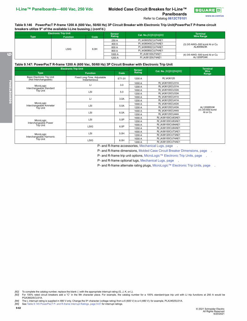
9-62 © 2021 Schneider Electric All Rights Reserved
6/20/2021
I-Line™ Panelboards—600 Vac, 250 Vdc Molded Case Circuit Breakes for I-Line™Panelboards www.se.com/us
Refer to Catalog 0612CT0101
Table 9.146 PowerPacT P-frame 1200 A (600 Vac, 50/60 Hz) 3P Circuit Breaker with Electronic Trip Unit(PowerPacT P-frame circuitbreakers utilize 9" of the available I-Line bussing.) (cont'd.)
Electronic Trip Unit SensorRating Cat. No.[82][83][84][85] Terminal
Wire RangeType Function Code
LSIG 6.0H
250 A P( )A36025(C)U74AE1
(3) 3/0 AWG–500 kcmil Al or CuAL800M23K
400 A P( )A36040(C)U74AE1600 A P( )A36060(C)U74AE1800 A P( )A36080(C)U74AE11000 A P( )A36100U74AE1 (4) 3/0 AWG–500 kcmil Al or Cu
AL1200P24K1200 A P( )A36120U74AE1
Table 9.147: PowerPacT R-frame 1200 A (600 Vac, 50/60 Hz) 3P Circuit Breaker with Electronic Trip UnitElectronic Trip Unit Sensor
Rating Cat. No. [82][83][84][85]TerminalWireRangeType Function Code
Basic Electronic Trip Unit(Not Interchangeable)
Fixed Long-Time, AdjustableInstantaneous ET1.01 1200 A R( )A36120
AL1200R53K(4) 3/0-600 kcmil
Al or Cu
MicroLogicInterchangeable Standard
Trip Unit
LI 3.01000 A R( )A36100CU31A1200 A R( )A36120CU31A
LSI 5.01000 A R( )A36100CU33A1200 A R( )A36120CU33A
MicroLogicInterchangeable Ammeter
Trip Unit
LI 3.0A1000 A R( )A36100CU41A1200 A R( )A36120CU41A
LSI 5.0A1000 A R( )A36100CU43A1200 A R( )A36120CU43A
LSI 6.0A1000 A R( )A36100CU44A1200 A R( )A36120CU44A
MicroLogicInterchangeable Power
Trip Unit
LSI 5.0P1000 A R( )A36100CU63AE11200 A R( )A36120CU63AE1
LSIG 6.0P1000 A R( )A36100CU64AE11200 A R( )A36120CU64AE1
MicroLogicInterchangeable Harmonic
Trip Unit
LSI 5.0H1000 A R( )A36100CU73AE11200 A R( )A36120CU73AE1
LSIG 6.0H1000 A R( )A36100CU74AE11200 A R( )A36120CU74AE1
P- and R-frame accessories, Mechanical Lugs, page .P- and R-frame dimensions, Molded Case Circuit Breaker Dimensions, page .P- and R-frame trip unit options, MicroLogic™ Electronic Trip Units, page .P- and R-frame optional lugs, Mechanical Lugs, page .P- and R-frame alternate rating plugs, MicroLogic™ Electronic Trip Units, page .
9PA
NELBOARDS
[82] To complete the catalog number, replace the blank ( ) with the appropriate interrupt rating (G, J, K, or L).[83] For 100% rated circuit breakers add a “C” in the 9th character place. For example, the catalog number for a 100% standard-type trip unit with LI trip functions at 250 A would be
PGA36025CU31A.[84] The L interrupt rating is supplied in 480 V only. Change the 5th character (voltage rating) from a 6 (600 V) to a 4 (480 V); for example, PLA34025U31A.[85] See Table 9.145 PowerPacT P- and R-frame Interrupt Ratings, page 9-61 for interrupt ratings.
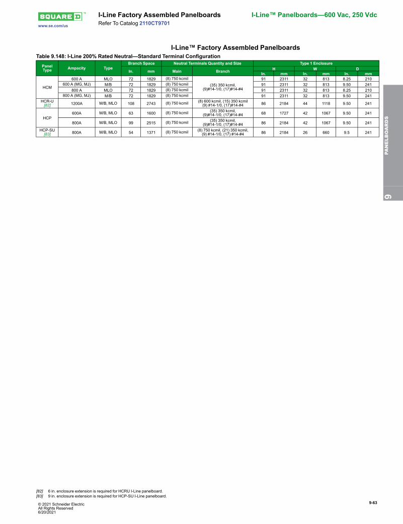
© 2021 Schneider Electric All Rights Reserved6/20/2021
9-63
www.se.com/us
I-Line Factory Assembled Panelboards I-Line™ Panelboards—600 Vac, 250 VdcRefer To Catalog 2110CT9701
I-Line™ Factory Assembled PanelboardsTable 9.148: I-Line 200% Rated Neutral—Standard Terminal Configuration
PanelType Ampacity Type
Branch Space Neutral Terminals Quantity and Size Type 1 Enclosure
In. mm Main Branch H W DIn. mm In. mm In. mm
HCM
600 A MLO 72 1829 (8) 750 kcmil(35) 350 kcmil,
(9)#14-1/0, (17)#14-#4
91 2311 32 813 8.25 210600 A (MG, MJ) M/B 72 1829 (8) 750 kcmil 91 2311 32 813 9.50 241
800 A MLO 72 1829 (8) 750 kcmil 91 2311 32 813 8.25 210800 A (MG, MJ) M/B 72 1829 (8) 750 kcmil 91 2311 32 813 9.50 241
HCR-U[82] 1200A M/B, MLO 108 2743 (8) 750 kcmil (8) 600 kcmil, (15) 350 kcmil
(9) #14-1/0, (17)#14-#4 86 2184 44 1118 9.50 241
HCP600A M/B, MLO 63 1600 (8) 750 kcmil (35) 350 kcmil,
(9)#14-1/0, (17)#14-#4 68 1727 42 1067 9.50 241
800A M/B, MLO 99 2515 (8) 750 kcmil (35) 350 kcmil,(9)#14-1/0, (17)#14-#4 86 2184 42 1067 9.50 241
HCP-SU[83] 800A M/B, MLO 54 1371 (8) 750 kcmil (8) 750 kcmil, (21) 350 kcmil,
(9) #14-1/0, (17) #14-#4 86 2184 26 660 9.5 241
9PA
NELBOARDS
[82] 6 in. enclosure extension is required for HCRU I-Line panelboard.[83] 9 in. enclosure extension is required for HCP-SU I-Line panelboard.
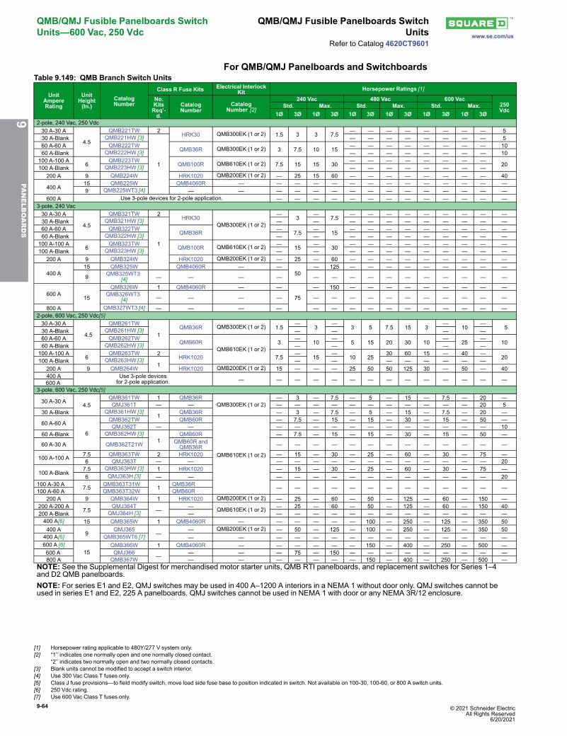
9-64 © 2021 Schneider Electric All Rights Reserved
6/20/2021
QMB/QMJ Fusible Panelboards SwitchUnits—600 Vac, 250 Vdc
QMB/QMJ Fusible Panelboards SwitchUnits www.se.com/us
Refer to Catalog 4620CT9601
For QMB/QMJ Panelboards and SwitchboardsTable 9.149: QMB Branch Switch Units
UnitAmpereRating
UnitHeight(In.)
CatalogNumber
Class R Fuse Kits Electrical InterlockKit Horsepower Ratings [1]
No.KitsReq’-d.
CatalogNumber
CatalogNumber [2]
240 Vac 480 Vac 600 Vac250Vdc
Std. Max. Std. Max. Std. Max.1Ø 3Ø 1Ø 3Ø 1Ø 3Ø 1Ø 3Ø 1Ø 3Ø 1Ø 3Ø
2-pole, 240 Vac, 250 Vdc30 A-30 A
4.5
QMB221TW 2HRK30 QMB300EK (1 or 2) 1.5 3 3 7.5
— — — — — — — — 5 30 A-Blank QMB221HW [3]
1
— — — — — — — — 560 A-60 A QMB222TW
QMB36R QMB300EK (1 or 2) 3 7.5 10 15— — — — — — — — 10
60 A-Blank QMB222HW [3] — — — — — — — — 10100 A-100 A
6QMB223TW
QMB100R QMB610EK (1 or 2) 7.5 15 15 30— — — — — — — —
20100 A-Blank QMB223HW [3] — — — — — — — —200 A 9 QMB224W HRK1020 QMB200EK (1 or 2) — 25 15 60 — — — — — — — — 40
400 A15 QMB225W QMB4060R — — — — — — — — — — — — — —9 QMB225WT3 [4] — — — — — — — — — — — — — — —
600 A Use 3-pole devices for 2-pole application. — — — — — — — — — — — — —3-pole, 240 Vac30 A-30 A
4.5
QMB321TW 2HRK30
QMB300EK (1 or 2)
—3
—7.5
— — — — — — — — — 30 A-Blank QMB321HW [3]
1
— — — — — — — — — — —60 A-60 A QMB322TW
QMB36R—
7.5—
15— — — — — — — — —
60 A-Blank QMB322HW [3] — — — — — — — — — — —100 A-100 A
6QMB323TW
QMB100R QMB610EK (1 or 2) —15
—30
— — — — — — — — —100 A-Blank QMB323HW [3] — — — — — — — — — — —
200 A 9 QMB324W HRK1020 QMB200EK (1 or 2) — 25 — 60 — — — — — — — — —
400 A15 QMB325W QMB4060R — —
50— 125 — — — — — — — — —
9 QMB325WT3[4] — — — — — — — — — — — — — — —
600 A15
QMB326W 1 QMB4060R — —
75
— 150 — — — — — — — — —QMB326WT3
[4] — — — — — — — — — — — — — — —
800 A QMB327WT3 [4] — — — — — — — — — — — — — — —2-pole, 600 Vac, 250 Vdc[5]30 A-30 A
4.5
QMB261TW
1QMB36R QMB300EK (1 or 2) 1.5
—3
—3 5 7.5 15 3
—10
— 5 30 A-Blank QMB261HW [3] — — — —
60 A-60 A QMB262TWQMB60R
QMB610EK (1 or 2)3
—10
—5 15 20 30 10
—25
—10 60 A-Blank QMB262HW [3] — — — —
100 A-100 A6
QMB263TW 2HRK1020 7.5
—15
—10 25
30 60 15 — 40 —20100 A-Blank QMB263HW [3]
1— — — — — — — —
200 A 9 QMB264W HRK1020 QMB200EK (1 or 2) 15 — — — 25 50 50 125 30 — 50 — 40400 A Use 3-pole devices
for 2-pole application. — — — — — — — — — — — — — —600 A3-pole, 600 Vac, 250 Vdc[5]
30 A-30 A4.5
QMB361TW 1 QMB36RQMB300EK (1 or 2)
— 3 — 7.5 — 5 — 15 — 7.5 — 20 —QMJ361T — — — — — — — — — — — — — 20 5
30 A-Blank QMB361HW [3]1 QMB36R — 3 — 7.5 — 5 — 15 — 7.5 — 20 —
60 A-60 A
6
QMB362TW QMB60R
QMB610EK (1 or 2)
— 7.5 — 15 — 15 — 30 — 15 — 50 —QMJ362T — — — — — — — — — — — — — — 10
60 A-Blank QMB362HW [3]1
QMB60R — 7.5 — 15 — 15 — 30 — 15 — 50 —
60 A-30 A QMB362T21W QMB60R andQMB36R — — — — — — — — — — — — —
100 A-100 A 7.5 QMB363TW 2 HRK1020 — 15 — 30 — 25 — 60 — 30 — 75 —6 QMJ363T — — — — — — — — — — — — — — 20
100 A-Blank7.5 QMB363HW [3] 1 HRK1020 — 15 — 30 — 25 — 60 — 30 — 75 —6 QMJ363H [3] — — — — — — — — — — — — — — 20
100 A-30 A 7.5 QMB363T31W 1 QMB36R — — — — — — — — — — — — —100 A-60 A QMB363T32W QMB60R200 A 9 QMB364W 1 HRK1020 QMB200EK (1 or 2) — 25 — 60 — 50 — 125 — 60 — 150 —
200 A-200 A7.5
QMJ364T—
— QMB610EK (1 or 2) — 25 — 60 — 50 — 125 — 60 — 150 40200 A-Blank QMJ364H [3] — — — — — — — — — — — — — —400 A[6] 15 QMB365W 1 QMB4060R — — — — — — 100 — 250 — 125 — 350 50400 A
9QMJ365
—— QMB200EK (1 or 2) — 50 — 125 — 100 — 250 — 125 — 350 50
400 A[6] QMB365WT6 [7] — — — — — — — — — — — — — — —600 A [6]
15QMB366W 1 QMB4060R — — — — — — 150 — 400 — 250 — 500 —
600 A QMJ366 — — — — 75 — 150 — — — — — — — — —800 A QMB367W — — — — — — — 150 — 400 — 250 — 500 —
NOTE: See the Supplemental Digest for merchandised motor starter units, QMB RTI panelboards, and replacement switches for Series 1–4and D2 QMB panelboards.NOTE: For series E1 and E2, QMJ switches may be used in 400 A–1200 A interiors in a NEMA 1 without door only. QMJ switches cannot beused in series E1 and E2, 225 A panelboards. QMJ switches cannot be used in NEMA 1 with door or any NEMA 3R/12 enclosure.
9PA
NELBOARDS
[1] Horsepower rating applicable to 480Y/277 V system only.[2] “1’’ indicates one normally open and one normally closed contact.
“2’’ indicates two normally open and two normally closed contacts.[3] Blank units cannot be modified to accept a switch interior.[4] Use 300 Vac Class T fuses only.[5] Class J fuse provisions—to field modify switch, move load side fuse base to position indicated in switch. Not available on 100-30, 100-60, or 800 A switch units.[6] 250 Vdc rating.[7] Use 600 Vac Class T fuses only.
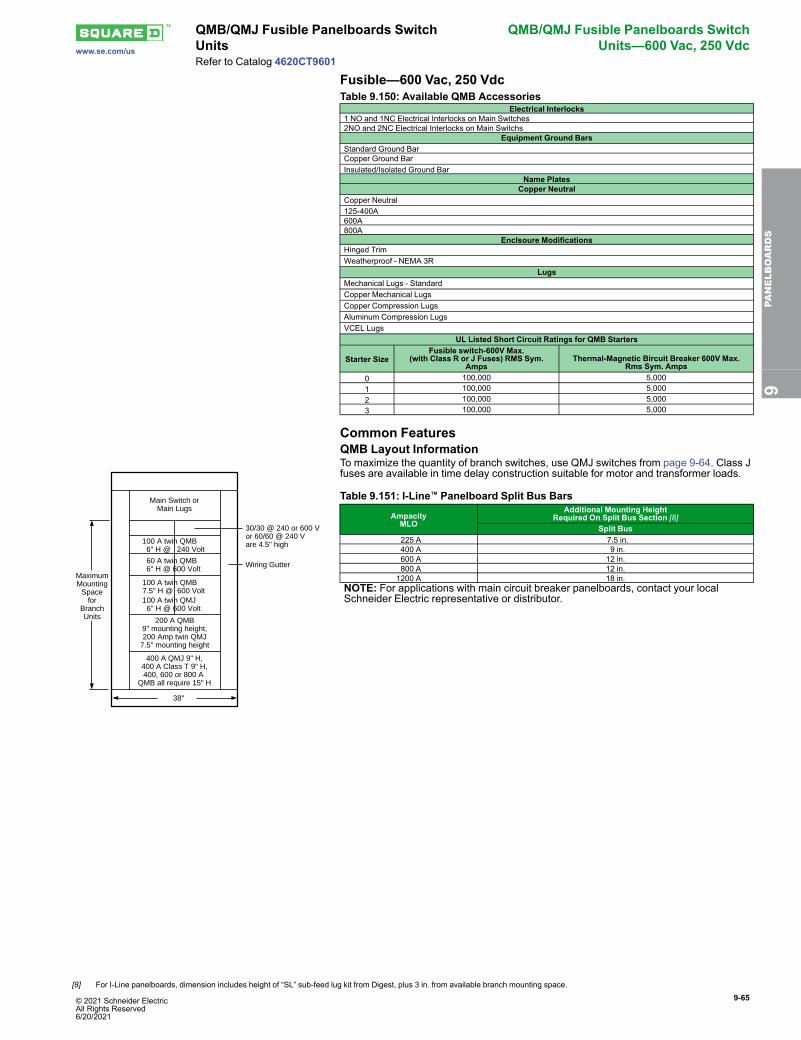
9-65
www.se.com/us
QMB/QMJ Fusible Panelboards SwitchUnits
QMB/QMJ Fusible Panelboards SwitchUnits—600 Vac, 250 Vdc
Refer to Catalog 4620CT9601
Fusible—600 Vac, 250 VdcTable 9.150: Available QMB Accessories
Electrical Interlocks1 NO and 1NC Electrical Interlocks on Main Switches2NO and 2NC Electrical Interlocks on Main Switchs
Equipment Ground BarsStandard Ground BarCopper Ground BarInsulated/Isolated Ground Bar
Name PlatesCopper Neutral
Copper Neutral125-400A600A800A
Enclsoure ModificationsHinged TrimWeatherproof - NEMA 3R
LugsMechanical Lugs - StandardCopper Mechanical LugsCopper Compression LugsAluminum Compression LugsVCEL Lugs
UL Listed Short Circuit Ratings for QMB Starters
Starter SizeFusible switch-600V Max.
(with Class R or J Fuses) RMS Sym.Amps
Thermal-Magnetic Bircuit Breaker 600V Max.Rms Sym. Amps
0 100,000 5,0001 100,000 5,0002 100,000 5,0003 100,000 5,000
Common FeaturesQMB Layout Information
MaximumMounting
Spacefor
BranchUnits
100 A twin QMB 6" H @ 240 Volt
60 A twin QMB6" H @ 600 Volt
100 A twin QMJ 6" H @ 600 Volt
100 A twin QMB7.5" H @ 600 Volt
200 A QMB9" mounting height,200 Amp twin QMJ
7.5" mounting height
38"
30/30 @ 240 or 600 V or 60/60 @ 240 Vare 4.5" high
Wiring Gutter
400 A QMJ 9" H,400 A Class T 9" H,400, 600 or 800 A
QMB all require 15" H
Main Switch orMain Lugs
To maximize the quantity of branch switches, use QMJ switches from page 9-64. Class Jfuses are available in time delay construction suitable for motor and transformer loads.
Table 9.151: I-Line™ Panelboard Split Bus Bars
AmpacityMLO
Additional Mounting HeightRequired On Split Bus Section [8]
Split Bus 225 A 7.5 in. 400 A 9 in. 600 A 12 in. 800 A 12 in.1200 A 18 in.
NOTE: For applications with main circuit breaker panelboards, contact your localSchneider Electric representative or distributor.
9PA
NELBOARDS
[8] For I-Line panelboards, dimension includes height of “SL” sub-feed lug kit from Digest, plus 3 in. from available branch mounting space.
© 2021 Schneider Electric All Rights Reserved6/20/2021
9-66 © 2021 Schneider Electric All Rights Reserved
6/20/2021
Special Features, Modifications, andTerminal Data
Special Featureswww.se.com/us
Refer to 2110CT9701, 1640CT0801, 4620CT9601
Main Circuit Breaker Without Overload Trip(Automatic Molded Case Switch)• (Not UL Listed)
Shunt Trip Circuit Breakers• NOTE: For molded case switch and automatic molded case switch short circuit currentratings, see Short Circuit Current Ratings (SCCR), page .
Special FeaturesFor information on the following special features, please see the Supplemental andObsolescence Digest.• Powerlogic™ metering [1]
• Customer equipment space (NQ and NF) [1]• Increased box depth [1]
• Increased gutters–top, bottom, and sides [1]
• Non-standard paint [1]• Welded base channel [1]• Type 1 gasketed [1]
• Type 2 drip hood [1]
• Type 3R/4/4X/5/12 stainless steel enclosure [1]
• Type 4X fiberglass enclosure [1]
• Stainless steel trim front [1]• Padlockable hasp [1]
• Special locks (Corbin, Yale, Best) [1]• Equal height boxes [1]
• Common trim to cover two equal height boxes [1]
• Panelboard skirt—hides conduits feeding a panelboard [1]
• Panelboard wireway—for terminating conduit in wireway endwall [1]• Keyed mechanical interlocking of two or more circuit breakers (I-Line and QMB) [1]• Motor operators (I-Line only)• Panelboard interiors and special fronts to fit existing boxes• A standard panelboard box has one blank endwall and one with knockouts. Blankendwalls or knockouts in both endwalls are also available [1]
9PA
NELBOARDS
[1] Supported by the Panelboard Product Selector.
© 2021 Schneider Electric All Rights Reserved6/20/2021
9-67
www.se.com/us
Terminal Data for NQ and NF Terminal Data Special Features, Modifications, andTerminal Data
Refer to Catalog 1670CT0701, 1640CT0801
NQ and NF Terminal DataTable 9.152: NQ Standard Aluminum Mechanical Lugs—Main Lugs
PanelType
AmpereRating Part Number Lug Wire Range
NQ
100 A NQALM1 one #6-2/0 Al or Cu225 A NQALM2 one #6-350 kcmil Al or Cu
400 A NQALM4 one 1/0-750 kcmil Al or Cu ortwo 1/0-350 kcmil Al or Cu
600 ANQALM6 two 1/0-750 kcmil Al or Cu
NQALM6A one 1/0-750 kcmil Al or Cuor three 250 kcmil Al-Cu
Table 9.153: NQ Standard Aluminum Mechanical Lugs—MainCircuit Breaker
PanelType Ampere Rating
CircuitBreakerType
Lug Wire Range [2]
NQ
100 A QOB one #4–#2/0 Al or Cu
150 A HD, HG, HJ,HL one #14–#3/0 Al or Cu
225 A QB, QD, QG,QJ one #4-300 kcmil Al or Cu
250 A JD, JG, JJ,JL one #3/0–350 kcmil Al or Cu [2]
400 A LA, LH one #1–600 kcmil Al or Cu ortwo #1–250 kcmil Al or Cu
600 A LD, LG, LJ,LL two #4/0-500 kcmil Al or Cu
Table 9.154: NF Standard Mechanical Lugs—Main LugsPanelType
AmpereRating Part Number Lug Wire Range
NF
125 A NFALM1 one #6–2/0 Al or Cu250 A NFALM2 one #6–350 kcmil Al or Cu400 A NFALM4 one #1/0–750 kcmil or two #1/0–350 kcmil Al or Cu600 A NFALM6 two 1/0-750 kcmil Al or Cu800 A NFALM8 three 1/0-750 kcmil Al or Cu
Table 9.155: NF Standard Mechanical Lugs—Main CircuitBreakerPanel Type Ampere Rating Circuit Breaker
Type Lug Wire Range [2]
NF
125 A ED, EG, EJ one #14–#2/0 Al or Cu150 A HD, HG, HJ, HL one #14–#3/0 Al or Cu
250 A JD, JG, JJ, JL one #3/0–350 kcmil Al or Cu [2]DJ one #2–600 Cu or #2–500 Al
400 A LA, LH one #1–600 kcmil or two #1–250kcmil Al or Cu
600 A LD, LG, LJ, LL,LR two #4/0–500 kcmil Al or Cu
Terminal DataTable 9.156: Standard Mechanical Lugs—Main Lugs
PanelType
AmpereRating Lug Wire Range [3]
Wire RangeWire Bending Space per NEC
Table 312-6 [3]
I-Line
100 A — —225 A one #6–300 kcmil Al or Cu one #6–300 kcmil Al or Cu
400 A two #2–600 kcmil Al or Cu one #2–600 kcmil Al or Cutwo #2–500 kcmil Al or Cu
600 A two #2–600 kcmil Al or Cu two #2–500 kcmil Al or Cu800 A (4) 3/0–750 kcmil Al or Cu (3) 3/0–500 kcmil Al or Cu1200 A (4) 3/0–750 kcmil Al or Cu (4) 3/0–500 kcmil Al or Cu
Table 9.157: Standard Mechanical Lugs—Main Circuit Breaker
PanelType
Am-pereRat-ing
Circuit BreakerType Lug Wire Range [3]
Wire RangeWire Bending Space per
NEC Table 312-6 [3]
I-Line
125 A BD, BG, BJ one #14-#2/0 AWG Alor Cu
one #14-#2/0 AWG Al orCu
150 A HD, HG, HJ, HL one #14-3/0 Al or Cu one #14-3/0 Al or Cu
250 A JD, JG, JJ, JL one #1/0-#4/0 Al or Cu one #1/0-300 kcmil Al orCu
400 A LA, LH one #1-600 or two #1-250 kcmil Al or Cu one #1-600 kcmil Al or Cu
800 A MG, MJ, PG,PJ, PL
three 3/0-500 kcmil Alor Cu
three 3/0-500 kcmil Al orCu
1200A
PG, PJ, PL,RGC, RJC,
RLCfour 3/0-500 kcmil Al or
Cufour 3/0-500 kcmil Al or
Cu
Table 9.158: Standard Mechanical Lugs—Main LugsPanelType
MainsAmpereRating
Lug Wire Range [3]Wire Range
Wire Bending Space per NECTable 312-6 [3]
QMB
225 A one #6–300 kcmil Al or Cu one #6–300 kcmil Al or Cu
400 Aone 3/0-500 kcmil Al or CU
and,one 3/0–750 kcmil Al or Cu
one 3/0-500 kcmil Al or CU and,one 3/0–750 kcmil Al or Cu
600 A two 3/0–500 kcmil Al or Cu two 3/0–500 kcmil Al or Cu
800 A (4) 3/0–750 kcmil Al or Cu (3) 3/0–500 kcmil Al or Cu ortwo 3/0–750 kcmil Al or Cu
1200 A (4) 3/0–750 kcmil Al or Cu (4) 3/0–500 kcmil Al or Cu or(4) 3/0–750 kcmil Al or Cu
1600 A VCEL compression lugs Standard.
Table 9.159: Standard Mechanical Lugs—Main SwitchPanelType
MainsAmpereRating
Lug Wire Range [3]Wire Range
Wire Bending Space per NECTable 312-6 [3]
QMB
200 A #4–300 kcmil Al or Cu one #4–300 kcmil Al or Cu400 A 3/0–600 kcmil Al or Cu 3/0–600 kcmil Al or Cu600 A 3/0–600 kcmil Al or Cu two 3/0–600 kcmil Al or Cu800 A 3/0–600 kcmil Al or Cu (3) 3/0–500 kcmil Al or Cu
Table 9.160: Standard Mechanical Lugs—QMB Branch Switch UnitsPanelType
SwitchAmpereRating
Lug Wire Range [3]Wire Range
Wire Bending Space per NECTable 312-6 [3]
QMB
30 A one #14–#2 Al or Cu one #14–#2 Al or Cu60 A one #14–#2 Al or Cu one #14–#2 Al or Cu100 A one #14–1/0 Al or Cu one #14–1/0 Al or Cu200 A one #4–300 kcmil Al or Cu one #4–300 kcmil Al or Cu400 A two 3/0–600 kcmil Al or Cu two 3/0–500 kcmil Al or Cu600 A two 3/0–600 kcmil Al or Cu two 3/0–500 kcmil Al or Cu800 A (3) 3/0–600 kcmil Al or Cu (3) 3/0–500 kcmil Al or Cu
Table 9.161: Standard Mechanical Lugs—QMJ Branch SwitchUnits [4]
PanelType
SwitchAmpereRating
Lug Wire Range [3]Wire Range
Wire Bending Space per NECTable 312-6 [3]
QMJ
30 A one #14–#2 Al or Cu one #14–#2 Al or Cu60 A one #14–#2 Al or Cu one #14–#2 Al or Cu100 A one #14–1/0 Al or Cu one #14–1/0 Al or Cu
200 A one #6–300 kcmil Al orCu one #6–300 kcmil Al or Cu
400 A one 1/0–750 kcmil Al orCu one 1/0–750 kcmil Al or Cu
600 A two 3/0–600 kcmil Al orCu two 3/0–600 kcmil Al or Cu
9PA
NELBOARDS
[2] The lug range shown is for the highest amperage of the circuit breaker frame shown in the table.[3] (#) = Number of conductors per phase.[4] Use only 90 oC insulated conductors based on an ampacity of 75 oC conductors.


![CSR Report 2015 [Digest]](https://img.pdfslide.net/doc/110x75/63257519cedd78c2b50c99c4/csr-report-2015-digest.jpg)