Embed Size (px)
Citation preview
1030 IEEE TRANSACTIONS ON INDUSTRY APPLICATIONS, VOL. 48, NO. 3, MAY/JUNE 2012
Design and Implementation of a 154-kV ±50-MvarTransmission STATCOM Based on 21-Level
Cascaded Multilevel ConverterBurhan Gultekin, Student Member, IEEE, Cem Ozgur Gerçek, Student Member, IEEE,
Tevhid Atalik, Student Member, IEEE, Mustafa Deniz, Student Member, IEEE, Nazan Biçer,Muammer Ermis, Member, IEEE, Kemal Nadir Kose, Cezmi Ermis, Erkan Koç,
Isik Çadirci, Adnan Açik, Yener Akkaya, Hikmet Toygar, and Semih Bideci
Abstract—In this research work, the design and implemen-tation of a 154-kV ±50-Mvar transmission static synchronouscompensator (T-STATCOM) have been carried out primarily forthe purposes of reactive power compensation and terminal voltageregulation and secondarily for power system stability. The imple-mented T-STATCOM consists of five 10.5-kV ±12-Mvar cascadedmultilevel converter (CMC) modules operating in parallel. Thepower stage of each CMC is composed of five series-connectedH-bridges (HBs) in each phase, thus resulting in 21-level line-to-line voltages. Due to modularity and flexibility of implementedHBs, each CMC module has reached a power density of
Manuscript received October 1, 2010; revised January 15, 2011; acceptedJanuary 22, 2011. Date of publication March 13, 2012; date of current ver-sion May 15, 2012. Paper 2010-IPCC-376.R1, presented at the 2010 IEEEEnergy Conversion Congress and Exposition, Atlanta, GA, September 12–16,and approved for publication in the IEEE TRANSACTIONS ON INDUSTRY
APPLICATIONS by the Industrial Power Converter Committee of the IEEEIndustry Applications Society. This work was supported by the Public ResearchSupport Group (KAMAG) of The Scientific and Technological ResearchCouncil of Turkey (TUBITAK).
B. Gultekin and C. O. Gerçek are with Middle East Technical Univer-sity, 06800 Ankara, Turkey, and also with the Power Electronics Depart-ment, Space Technologies Research Institute, The Scientific and TechnologicalResearch Council of Turkey (TUBITAK), 06800 Ankara, Turkey (e-mail:[email protected]; [email protected]).
T. Atalik is with Baskent University, 06810 Ankara, Turkey, and also withthe Space Technologies Research Institute, The Scientific and TechnologicalResearch Council of Turkey (TUBITAK), 06531 Ankara, Turkey (e-mail:[email protected]).
M. Deniz, N. Biçer, C. Ermis, and E. Koç are with the Space TechnologiesResearch Institute, The Scientific and Technological Research Council ofTurkey (TUBITAK), 06531 Ankara, Turkey (e-mail: [email protected]; [email protected]; [email protected]; [email protected]).
M. Ermis is with Middle East Technical University, 06800 Ankara, Turkey(e-mail: [email protected]).
K. N. Kose was with the Power Electronics Department, Space TechnologiesResearch Institute, The Scientific and Technological Research Council ofTurkey (TUBITAK), 06531 Ankara, Turkey. He is now with Magellan PowerSystems, Perth, WA 6163, Australia (e-mail: [email protected]).
I. Çadirci is with the Space Technologies Research Institute, The Scientificand Technological Research Council of Turkey (TUBITAK), 06531 Ankara,Turkey, and also with Hacettepe University, 06800 Ankara, Turkey (e-mail:[email protected]).
A. Açik was with the Power Electronics Department, Space TechnologiesResearch Institute, The Scientific and Technological Research Council ofTurkey (TUBITAK), 06531 Ankara, Turkey. He is now with Endoks EnergySystems, 06370 Ankara, Turkey (e-mail: [email protected]).
Y. Akkaya, H. Toygar, and S. Bideci are with the Turkish Electric-ity Transmission Company (TEIAS), 06490 Ankara, Turkey (e-mail: [email protected]; [email protected]; [email protected]).
Color versions of one or more of the figures in this paper are available onlineat http://ieeexplore.ieee.org.
Digital Object Identifier 10.1109/TIA.2012.2190690
250 kvar/m3, thus making the mobility of the system imple-mentable. DC-link capacitor voltages of HBs are perfectly bal-anced by means of the modified selective swapping algorithmproposed. The field tests carried out at full load in the 154-kVtransformer substation where T-STATCOM is installed haveshown that the steady-state and transient responses of the systemare quite satisfactory.
Index Terms—Modified selective swapping (MSS), multilevelconverters (MCs), terminal voltage regulation, transmission staticsynchronous compensator (STATCOM) (T-STATCOM).
I. INTRODUCTION
F LEXIBLE ac transmission systems are being increasinglyused in power systems, to enhance the system utilization
and power transfer capacity as well as the stability, security,reliability, and power quality of ac system interconnections.The static synchronous compensator (STATCOM) convertersused in transmission system applications should control a fewtens or hundreds of megavars, operate at medium voltage (MV)levels, and are connected to extrahigh-voltage or high-voltage(HV) transmission system buses via specially designed cou-pling transformers. These are called transmission STATCOMs(T-STATCOMs) in the literature.
Various multilevel converter (MC) topologies operating atswitching frequencies at or near the supply frequency fit best tothe needs of T-STATCOMs [1]–[6]. In T-STATCOM systems,the use of six-pulse converters is not feasible owing to theneed for series-connected power semiconductor switches andmuch higher switching frequencies for waveform synthesizing.MCs for T-STATCOM applications are classified into threegroups [1]:
1) diode-clamped MCs;2) flying capacitor MCs;3) cascaded MCs (CMCs).
The equalization problem of the dc-link capacitor voltagesis the common drawback of these MC topologies [1]–[9].Among these, CMC topology is based on H-bridge (HB)circuits connected in series and has the advantage of modu-larity, flexibility, and lower component count in comparisonwith the others [1]. Commercial CMC-based T-STATCOMsemploy either gate turnoff thyristor (GTO) or gate-commutatedthyristor (GCT)/integrated GCT devices with inverse-parallel-connected power diodes. To limit di/dt overvoltages on GTOs
0093-9994/$31.00 © 2012 IEEE
GULTEKIN et al.: DESIGN AND IMPLEMENTATION OF 154-kV ±50-Mvar T-STATCOM BASED ON 21-LEVEL CMC 1031
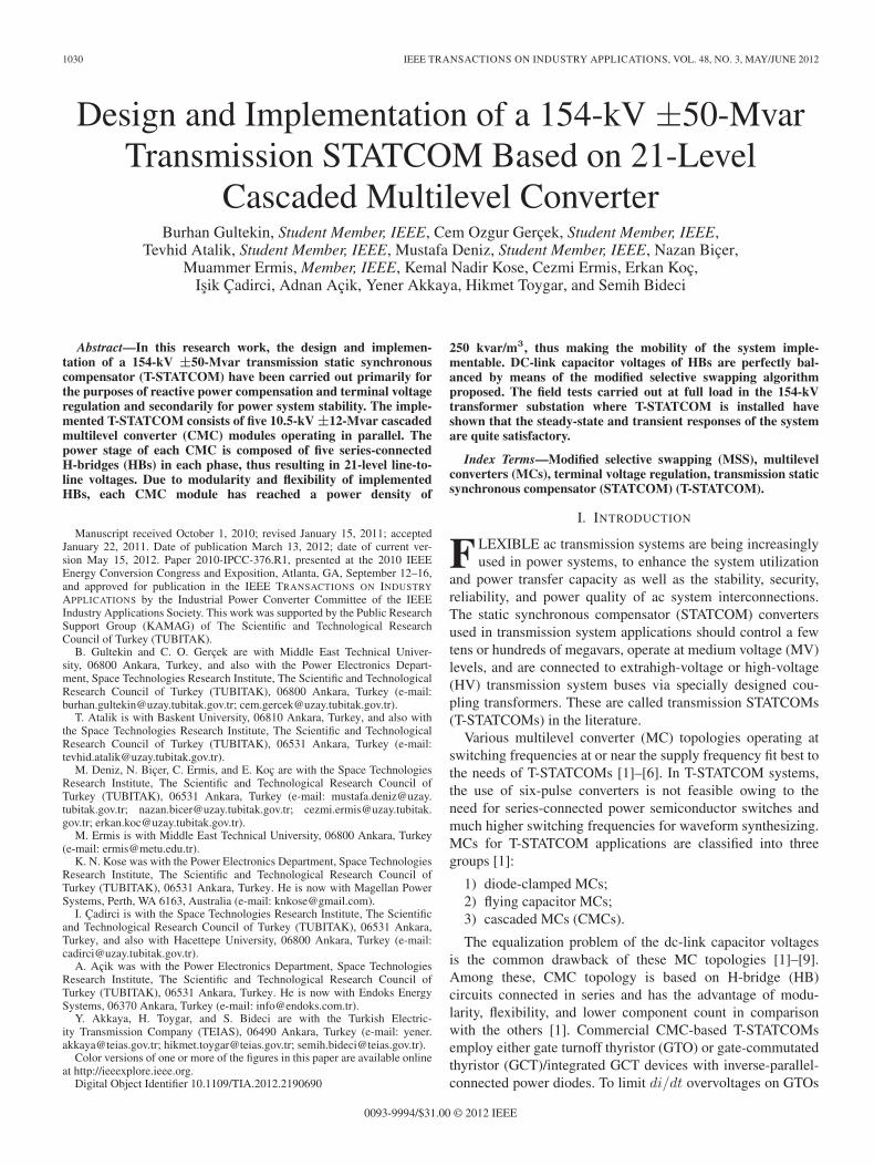
Fig. 1. Simplified single-line diagram of the T-STATCOM.
during turnoff operation, bulky snubber circuits were used [8],[9]. To equalize individual capacitor voltages, high-frequencyinsulated-gate bipolar transistor (IGBT)-based auxiliary cir-cuits supplied from the low-voltage side were employed.Specially designed isolating transformers were used to isolateauxiliary circuits from the power stage of CMC.
An important contribution to the solution of voltage equal-ization problem of dc-link capacitors is known as the selectiveswapping algorithm [7] which can be embedded in the controlalgorithm of CMC, thus eliminating the need for bulky auxil-iary circuits. Although the effectiveness of voltage equalizationalgorithm decreases as the number of HBs connected in seriesand/or peak-to-peak ripple content of the capacitor voltageincrease/s, it provides the lowest switching frequency for thepower semiconductors.
In this research and technology development work,±50-Mvar 21-level CMC-based T-STATCOM has been de-signed and implemented primarily for the purposes of reactivepower compensation and terminal voltage regulation and sec-ondarily for power system stability. Since the operating voltage
of CMC is chosen to be 10.5 kV line-to-line, it is connectedto 154-kV line-to-line transmission bus through a speciallydesigned 50/62.5-MVA Y–Y-connected (YNyn vector group)coupling transformer. The power stage of the CMC is composedof five series-connected HBs in each phase. The selectiveswapping algorithm in [7] has been improved to balance dc-linkcapacitor voltages perfectly at the expense of higher switchingfrequency and, hence, switching losses.
This implementation is the first industrial application ofHV-IGBT-based CMC and the modified capacitor voltage bal-ancing algorithm for T-STATCOM technology. The CMC, itscontrol system, and the deionized water cooling system exclud-ing the water-to-air heat exchanger are located on a speciallydesigned trailer to equip T-STATCOM with the advantage ofmobility in addition to modularity and flexibility.
II. SYSTEM DESCRIPTION
Fig. 1 shows the schematic diagram of a 154-kV ±50-MvarT-STATCOM system. It is composed of five 10.5-kV ±12-Mvar
1032 IEEE TRANSACTIONS ON INDUSTRY APPLICATIONS, VOL. 48, NO. 3, MAY/JUNE 2012
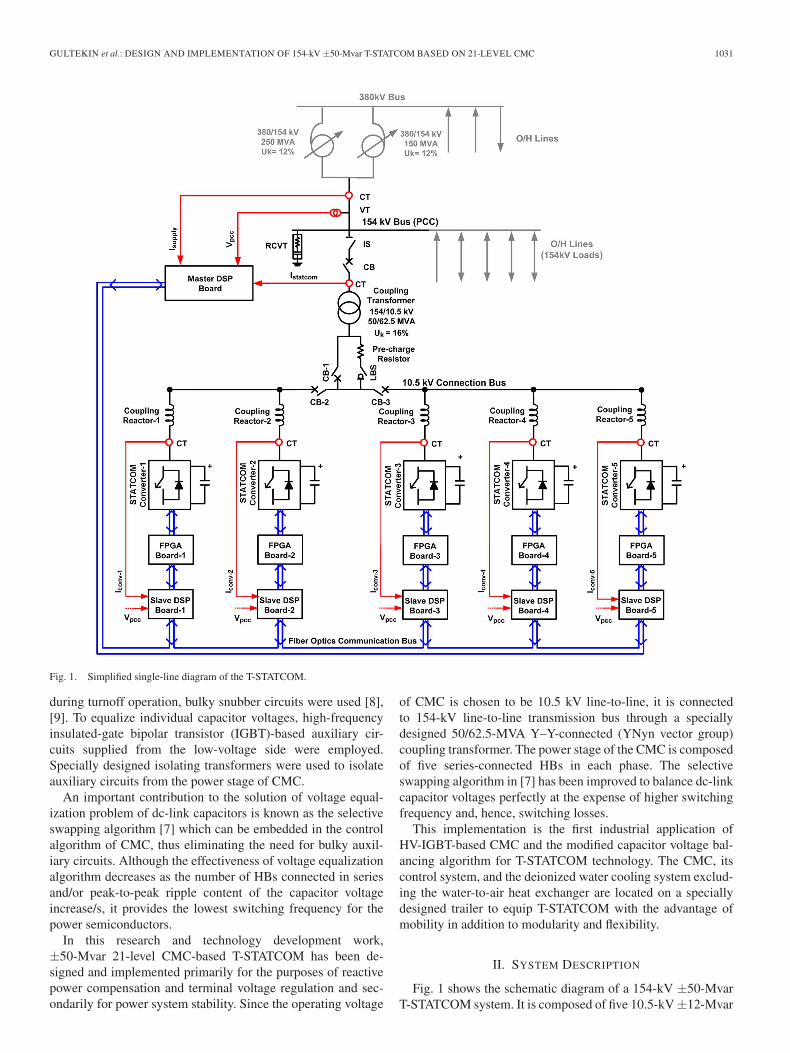
Fig. 2. 154-kV ±50-Mvar T-STATCOM based on 21-level CMCs. (a) Interior view of trailer with power stages. (b) Control cabinets. (c) Trailer for ±50-MvarT-STATCOM on road (W × L × H : 3700 mm × 16 800 mm × 4300 mm). (d) General view of T-STATCOM.
CMC modules which are connected in parallel via air-corereactors. The combination of five STATCOM modules is thenconnected to 154-kV bus via a 154/10.5-kV 50/62.5-MVAY–Y-connected coupling transformer. The neutral point ofthe primary is solidly grounded, while that of the secondaryis grounded via a 6.93-Ω grounding resistor to limit line-to-ground fault current to 1 kA. A 21-level CMC-based T-STATCOM has been designed and implemented primarily forthe purposes of reactive power compensation and terminalvoltage regulation and secondarily for power system stability.It is equipped with a digital control system, except some analoginterface and protection circuits.
A master controller manages all control and most of theprotection facilities by sending the necessary commands to theslave control units. All controllers are built up by using up-to-date digital signal processor (DSP; TI-TMS320 F28335) andfield-programmable gate array (FPGA; 1 500 000-gate XILINXSpartan-3) technologies.
The 11-level line-to-neutral voltage and, hence, 21-level line-to-line voltage waveforms are created by using five series-connected HBs in each phase of the Y-connected CMC module.The developed ±50-Mvar T-STATCOM has been installed in
380-kV/154-kV Sincan Transformer Substation, Ankara, asshown in Fig. 2. Table I summarizes the technical specificationsof each HB and CMC module and the resulting T-STATCOMsystem.
The dc link of each HB is formed by connecting two4.6-mF metallized polypropylene (MKP) capacitors in parallel.In constructing 11 levels in line-to-neutral waveforms and21 levels in line-to-line voltage waveforms, K dc links areconnected in series while the remaining 5 − K dc links arebypassed by properly chosen power semiconductor switchingpatterns in each phase of the CMC module. Therefore, theequivalent dc-link capacitance Ceqv of each CMC module isgiven by
Ceqv = 9.2/K mF (1)
where K = 1, 2, . . . , 5 is the number of dc-link capacitorsconnected in series out of five.
The coupling transformer (ONAN/ONAF: Oil Natural AirNatural/Oil Natural Air Forced), HV and MV switchgearequipment, input filter reactors, and the water-to-air heat ex-changer of this system are installed outdoor [Fig. 2(d)]. Thepower stage, the control system, and part of the deionized
GULTEKIN et al.: DESIGN AND IMPLEMENTATION OF 154-kV ±50-Mvar T-STATCOM BASED ON 21-LEVEL CMC 1033
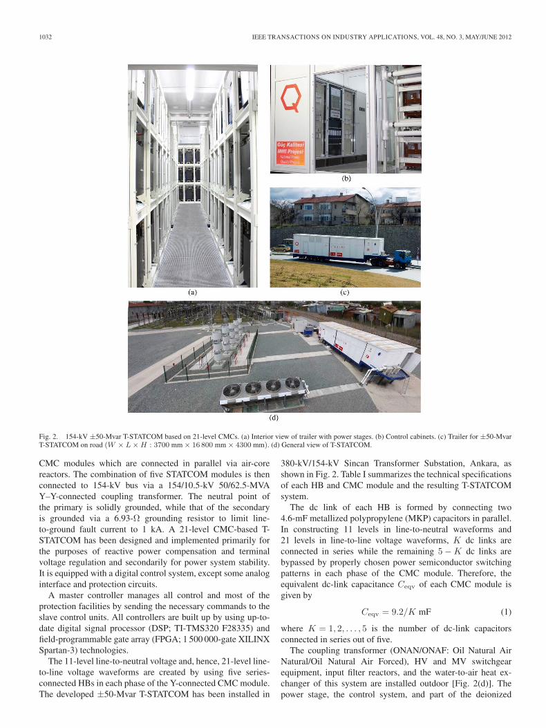
TABLE IT-STATCOM, CMC, AND HB SPECIFICATIONS
Fig. 3. Simplified single-line diagram of T-STATCOM.
Fig. 4. Phasor diagram for lossy system (exaggerated).
water cooling system excluding the water-to-air heat ex-changer are placed into a nonmagnetic container mounted ona trailer [Fig. 2(c)]. This makes possible easy relocation of theT-STATCOM to another problematic point of the transmissionsystem whenever this is required.
III. OPERATING PRINCIPLES
A. Reactive Power Control
The single-phase Y-equivalent circuit model of theT-STATCOM and its phasor diagram are shown in Figs. 3 and4, respectively, whereE ′
s internal source voltage referred to voltage source con-verter (VSC) side;
X ′s internal source reactance referred to VSC side;
PCC point of common coupling;
V ′s fundamental voltage component at PCC referred to
VSC side;X total series reactance, including leakage reactance of
the coupling transformer referred to VSC side andreactance of the input filter reactors;
R total series resistance, including internal resistance ofthe coupling transformer referred to VSC side andinternal resistance of the input filter reactors;
Vc fundamental component of the VSC ac voltage;Ic fundamental component of the VSC line current;θ phase angle between
−→Vc and
−→Ic ;
δ power angle between−→V ′
s and−→Vc;
φ impedance angle tan−1(X/R);Ps, Qs active and reactive power inputs to T-STATCOM at
PCC;Pc, Qc active and reactive power inputs to VSC.
In Fig. 3, all voltages and currents are rms values, and activeand reactive powers are per-phase values. Ps, Pc, Qs, and Qc inFig. 3 can be expressed in terms of terminal quantities V ′
s andVc and angles θ and δ as follows:
Ps = V ′sIc cos(θ + δ) (2)
Pc = VcIc cos θ (3)
Qs = V′
s Ic sin(θ + δ) (4)
Qc = VcIc sin θ. (5)
Ic and θ in (2)–(5) can be eliminated as given in Appendix A.These operations yield the power expressions in the following:
Ps =V ′s [VcX sin δ − VcR cos δ + V ′
sR] /Z2 (6)
Pc =Vc [V ′sX sin δ + V ′
sR cos δ − VcR] /Z2 (7)
Qs =V ′s [V ′
sX − VcX cos δ − VcR sin δ] /Z2 (8)
Qc =Vc [V ′sX cos δ − VcX − V ′
sR sin δ] /Z2 (9)
where Z =√
(R2 + X2).Pc can be related to Ps in terms of power dissipation on R
as in (10). In a similar way, Qc can be related to Qs in terms ofthe reactive power absorbed by X
Pc =Ps − I2c R (10)
Qc =Qs − I2c X. (11)
Since I2c R plays no basic part in the control of reactive power
and since R is small in comparison with X , R in Fig. 3 and in(6)–(10) will be neglected. According to this assumption, activepower P transferred between
−→V ′
s and−→Vc can be expressed as in
P = Ps = Pc = (V ′sVc/X) sin δ. (12)
P is very small during the operation of the VSC in the steadystate, to supply only the VSC losses, and hence, δ takes a verysmall value (δ is around 0.017 rad ≡ 1◦). For such small valuesof δ, sin δ ≈ δ holds, and hence, P can be approximated by
P = (V ′sVc/X) δ. (13)
By substituting R = 0, (8) and (9) will reduce respectively to
Qs =V ′s [(V ′
s − Vc cos δ) /X] (14)
Qc =Vc [(V ′s cos δ − Vc) /X] . (15)
1034 IEEE TRANSACTIONS ON INDUSTRY APPLICATIONS, VOL. 48, NO. 3, MAY/JUNE 2012
Since δ is very small, cos δ ≈ 1 holds. Hence, (14) and (15)can be approximated, respectively, to
Qs =V ′s [(V ′
s − Vc) /X] (16)Qc =Vc [(V ′
s − Vc) /X] . (17)
Complex power input−→S = P + jQs to the T-STATCOM is
defined according to power sink convention. P is always posi-tive in the steady state to compensate for coupling transformer,series filter reactor, and VSC losses. However, the sign of Qs
depends upon the operation mode of the T-STATCOM, i.e., pos-itive for inductive mode of operation and negative for capacitivemode. θ is positive (≈ +π/2) for inductive mode of operationin the steady state, while it is negative (≈ −π/2) for capacitivemode. The transition between capacitive and inductive modesof operations occurs when Qc = I2
c Xc, which corresponds tounity power factor (PF) operation of the T-STATCOM at PCC.
Active power into the T-STATCOM is controlled by varyingδ in order to keep the dc-link capacitor voltages constant ata prespecified value over the entire operating range in bothtransient state and steady state. δ is always positive in thesteady state under the assumption of R = 0. However, δ mayhave negative values for inductive operation mode of the T-STATCOM (V ′
s > Vc) when R is not neglected. This occurs forvery small values of δ and even for a practical X/R ratio. Thisphenomenon is apparent from (6) and (7). This small negativevalue for δ does not reverse the direction of real power flowfor the operation of the system shown in Fig. 3 in the steadystate. For capacitive operation mode, however, since V ′
s < Vc,δ is always positive as can be understood from (6) and (7).
Qs and Qc are controlled by varying Vc by pulsewidth mod-ulation technique. If Vc is made smaller than V ′
s , T-STATCOMoperates in inductive operation mode as can be understood from(16). On the other hand, if Vc is made sufficiently higher thanV ′
s , it starts to operate in capacitive operation mode and deliversreactive power to the supply. In practice, the situation is morecomplex, because the supply is not an infinite bus. That is, thecapacitive operation mode causes a rise in the supply voltageV ′
s , while the inductive operation mode causes a drop.
B. Wave Shaping
The input voltage waveform of VSC Vc(t) will be approxi-mated to a pure sinusoidal voltage at supply frequency by usingthe CMC topology and selective harmonic elimination method(SHEM). It is well known that the number of voltage levels nin the staircase voltage waveform in Fig. 5 produced by CMCis defined by
n = 2s + 1 in the line-to-neutral voltage (18)n = 4s + 1 in the line-to-line voltage (19)
where s is the number of HBs in one phase. As an example,in the T-STATCOM described in this paper, five HBs areconnected in series in each phase to form a Y-connected MCtopology. This CMC yields 11 voltage levels in the line-to-neutral voltage waveform and 21 voltage levels in the line-to-line voltage waveform.
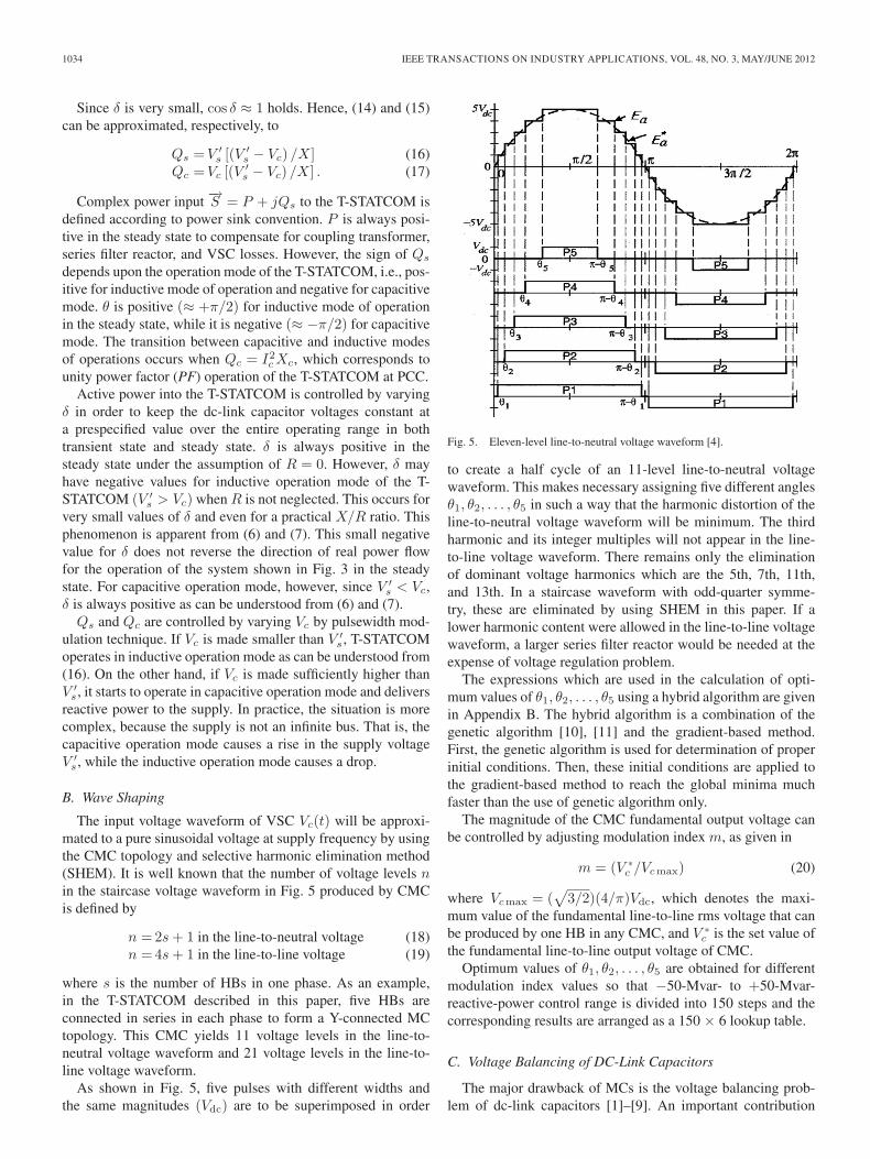
As shown in Fig. 5, five pulses with different widths andthe same magnitudes (Vdc) are to be superimposed in order
Fig. 5. Eleven-level line-to-neutral voltage waveform [4].
to create a half cycle of an 11-level line-to-neutral voltagewaveform. This makes necessary assigning five different anglesθ1, θ2, . . . , θ5 in such a way that the harmonic distortion of theline-to-neutral voltage waveform will be minimum. The thirdharmonic and its integer multiples will not appear in the line-to-line voltage waveform. There remains only the eliminationof dominant voltage harmonics which are the 5th, 7th, 11th,and 13th. In a staircase waveform with odd-quarter symme-try, these are eliminated by using SHEM in this paper. If alower harmonic content were allowed in the line-to-line voltagewaveform, a larger series filter reactor would be needed at theexpense of voltage regulation problem.
The expressions which are used in the calculation of opti-mum values of θ1, θ2, . . . , θ5 using a hybrid algorithm are givenin Appendix B. The hybrid algorithm is a combination of thegenetic algorithm [10], [11] and the gradient-based method.First, the genetic algorithm is used for determination of properinitial conditions. Then, these initial conditions are applied tothe gradient-based method to reach the global minima muchfaster than the use of genetic algorithm only.
The magnitude of the CMC fundamental output voltage canbe controlled by adjusting modulation index m, as given in
m = (V ∗c /Vcmax) (20)
where Vcmax = (√
3/2)(4/π)Vdc, which denotes the maxi-mum value of the fundamental line-to-line rms voltage that canbe produced by one HB in any CMC, and V ∗
c is the set value ofthe fundamental line-to-line output voltage of CMC.
Optimum values of θ1, θ2, . . . , θ5 are obtained for differentmodulation index values so that −50-Mvar- to +50-Mvar-reactive-power control range is divided into 150 steps and thecorresponding results are arranged as a 150 × 6 lookup table.
C. Voltage Balancing of DC-Link Capacitors
The major drawback of MCs is the voltage balancing prob-lem of dc-link capacitors [1]–[9]. An important contribution
GULTEKIN et al.: DESIGN AND IMPLEMENTATION OF 154-kV ±50-Mvar T-STATCOM BASED ON 21-LEVEL CMC 1035
to the solution of voltage equalization problem of dc-linkcapacitors is known as the selective swapping algorithm [7]which can be embedded in the control algorithm of CMC. It iscalled the swapping algorithm because, at each level change (θ1
to θ5 in Fig. 5), the previous set of HBs which are in operationis going to be interchanged with a new set in each phase of eachCMC module. It is called selective swapping algorithm becausethe swapping operation is done according to the values of dc-link capacitor voltages.
If the current and the voltage are both positive or ne-gative, the input power to the HB converter is positive, andhence, the associated dc-link capacitor is going to be charged.On the other hand, if one of these quantities is positive while theother is negative, the input power to HB is negative, and hence,the associated dc-link capacitor is going to be discharged.Therefore, in order to determine which HB/s are going to beoperated at each level change, the values of individual dc-linkcapacitor voltages, polarity of the voltage, and direction of thecurrent should be measured.
The polarity of the input voltage to HBs is determinedindirectly by using a phase-locked loop (PLL) circuit whichis locked to line-to-neutral voltage at PCC. The digital signalproduced by PLL is phase advanced or delayed by power(load) angle δ in Fig. 4 to determine the zero-crossing point ofthe CMC modules’ fundamental line-to-neutral voltage. Afterdetermining the new status of the dc-link capacitors (chargingor discharging) by this way, HBs having the lowest dc-linkvoltages will be put into operation for charging, and HBshaving the highest dc-link voltages will be put into operationfor discharging mode. This method is called the conventionalselective swapping (CSS) in this paper. The CSS gives mini-mum switching frequency for the power semiconductors.
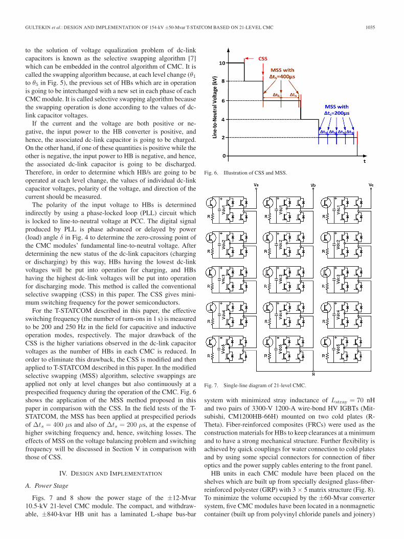
For the T-STATCOM described in this paper, the effectiveswitching frequency (the number of turn-ons in 1 s) is measuredto be 200 and 250 Hz in the field for capacitive and inductiveoperation modes, respectively. The major drawback of theCSS is the higher variations observed in the dc-link capacitorvoltages as the number of HBs in each CMC is reduced. Inorder to eliminate this drawback, the CSS is modified and thenapplied to T-STATCOM described in this paper. In the modifiedselective swapping (MSS) algorithm, selective swappings areapplied not only at level changes but also continuously at aprespecified frequency during the operation of the CMC. Fig. 6shows the application of the MSS method proposed in thispaper in comparison with the CSS. In the field tests of the T-STATCOM, the MSS has been applied at prespecified periodsof Δts = 400 μs and also of Δts = 200 μs, at the expense ofhigher switching frequency and, hence, switching losses. Theeffects of MSS on the voltage balancing problem and switchingfrequency will be discussed in Section V in comparison withthose of CSS.
IV. DESIGN AND IMPLEMENTATION
A. Power Stage
Figs. 7 and 8 show the power stage of the ±12-Mvar10.5-kV 21-level CMC module. The compact, and withdraw-able, ±840-kvar HB unit has a laminated L-shape bus-bar
Fig. 6. Illustration of CSS and MSS.
Fig. 7. Single-line diagram of 21-level CMC.
system with minimized stray inductance of Lstray = 70 nHand two pairs of 3300-V 1200-A wire-bond HV IGBTs (Mit-subishi, CM1200HB-66H) mounted on two cold plates (R-Theta). Fiber-reinforced composites (FRCs) were used as theconstruction materials for HBs to keep clearances at a minimumand to have a strong mechanical structure. Further flexibility isachieved by quick couplings for water connection to cold platesand by using some special connectors for connection of fiberoptics and the power supply cables entering to the front panel.
HB units in each CMC module have been placed on theshelves which are built up from specially designed glass-fiber-reinforced polyester (GRP) with 3 × 5 matrix structure (Fig. 8).To minimize the volume occupied by the ±60-Mvar convertersystem, five CMC modules have been located in a nonmagneticcontainer (built up from polyvinyl chloride panels and joinery)
1036 IEEE TRANSACTIONS ON INDUSTRY APPLICATIONS, VOL. 48, NO. 3, MAY/JUNE 2012
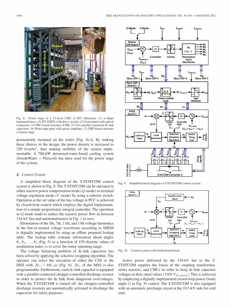
Fig. 8. Power stage of a 21-level CMC at MV laboratory. (1) L-shapelaminated buses. (2) HV IGBTs with drive circuits. (3) Front panel with opticalconnectors. (4) FRC-based structure of HB. (5) Two parallel-connected dc-linkcapacitors. (6) Water pipe pairs with quick couplings. (7) GRP-based structureof power stage.
permanently mounted on the trailer [Fig. 2(c)]. By makingthese choices in the design, the power density is increased to250 kvar/m3, thus making mobility of the system imple-mentable. A 700-kW deionized-water-based cooling system(SwedeWater + Flexcoil) has been used for the power stageof the system.
B. Control System
A simplified block diagram of the T-STATCOM controlsystem is shown in Fig. 9. The T-STATCOM can be operated ineither reactive power compensation mode (Q-mode) or terminalvoltage regulation mode (V -mode) by using a selector switch.Operation at the set value of the bus voltage at PCC is achievedby closed-loop control which employs the digital implementa-tion of a simple proportional–integral controller. The operationin Q-mode tends to reduce the reactive power flow in between154-kV bus and autotransformers in Fig. 1 to zero.
Elimination of the 5th, 7th, 11th, and 13th voltage harmonicsin the line-to-neutral voltage waveforms according to SHEMis digitally implemented by using an offline prepared lookuptable. The lookup table contains information about anglesθ1, θ2, . . . , θ5 (Fig. 5) as a function of 150 discrete values ofmodulation index m to cover the entire operating range.
The voltage balancing problem of dc-link capacitors hasbeen solved by applying the selective swapping algorithm. Theoperator can select the execution of either the CSS or theMSS with Δts = 400 μs (Fig. 6). Δts of the MSS is alsoprogrammable. Furthermore, each dc-link capacitor is equippedwith a parallel-connected chopper-controlled discharge resistorin order to protect the dc link from dangerous overvoltages.When the T-STATCOM is turned off, the chopper-controlleddischarge resistors are automatically activated to discharge thecapacitors for safety purposes.
Fig. 9. Simplified block diagram of T-STATCOM control system.
Fig. 10. Control system with feedforward block.
Active power delivered by the 154-kV bus to the T-STATCOM supplies the losses of the coupling transformer,series reactors, and CMCs in order to keep dc-link capacitorvoltages at their rated values (1900 Vdc,mean). This is achievedby employing a digitally implemented closed-loop power (load)angle (δ in Fig. 9) control. The T-STATCOM is also equippedwith an automatic precharge circuit at the 10.5-kV side for coldstart.
GULTEKIN et al.: DESIGN AND IMPLEMENTATION OF 154-kV ±50-Mvar T-STATCOM BASED ON 21-LEVEL CMC 1037
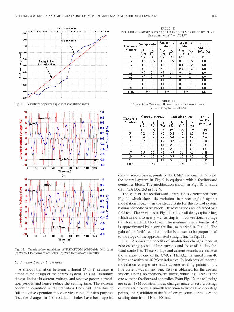
Fig. 11. Variations of power angle with modulation index.
Fig. 12. Transient-free transitions of T-STATCOM (CMC-side field data).(a) Without feedforward controller. (b) With feedforward controller.
C. Further Design Objectives
A smooth transition between different Q or V settings isaimed at the design of the control system. This will minimizethe oscillations in current, voltage, and reactive power in transi-tion periods and hence reduce the settling time. The extremeoperating condition is the transition from full capacitive tofull inductive operation mode or vice versa. For this purpose,first, the changes in the modulation index have been applied
TABLE IIPCC LINE-TO-GROUND VOLTAGE HARMONICS MEASURED BY RCVT
SENSORS (maxV = 170 kV)
TABLE III154-kV-SIDE CURRENT HARMONICS AT RATED POWER
(Il = 188 A; Isc = 20 kA)
only at zero-crossing points of the CMC line current. Second,the control system in Fig. 9 is equipped with a feedforwardcontroller block. The modification shown in Fig. 10 is madeon FPGA Board-3 in Fig. 9.
The gain of the feedforward controller is determined fromFig. 11 which shows the variations in power angle δ againstmodulation index m in the steady state for the control systemhaving no feedforward block. These variations are obtained by afield test. The m values in Fig. 11 include all delays (phase lag)which amount to nearly −2◦ arising from conventional voltagetransformers, PLL block, etc. The nonlinear characteristic of δis approximated by a straight line, as marked in Fig. 11. Thegain of the feedforward controller is chosen to be proportionalto the slope of the approximated straight line in Fig. 11.
Fig. 12 shows the benefits of modulation changes made atzero-crossing points of line currents and those of the feedfor-ward controller. These voltage and current records are made atthe ac input of one of the CMCs. The Qset is varied from 40Mvar capacitive to 40 Mvar inductive. In both sets of records,modulation changes are made at zero-crossing points of theline current waveforms. Fig. 12(a) is obtained for the controlsystem having no feedforward block, while Fig. 12(b) is theone with the feedforward controller. From Fig. 12, the followingare seen: 1) Modulation index changes made at zero crossingsof currents provide a smooth transition between two operatingpoints, and 2) addition of the feedforward controller reduces thesettling time from 140 to 100 ms.
1038 IEEE TRANSACTIONS ON INDUSTRY APPLICATIONS, VOL. 48, NO. 3, MAY/JUNE 2012
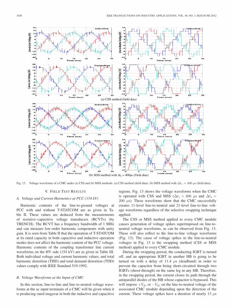
Fig. 13. Voltage waveforms of a CMC under (a) CSS and (b) MSS methods. (a) CSS method (field data). (b) MSS method with Δts = 400 μs (field data).
V. FIELD TEST RESULTS
A. Voltage and Current Harmonics at PCC (154 kV)
Harmonic contents of the line-to-ground voltages atPCC with and without T-STATCOM are as given in Ta-ble II. These values are deduced from the measurementsof resistive–capacitive voltage transducers (RCVTs) (byTRENCH). The RCVT has a frequency bandwidth of 1 MHzand can measure low-order harmonic components with unitygain. It is seen from Table II that the operation of T-STATCOMat its rated capacity in both capacitive and inductive operationmodes does not affect the harmonic content of the PCC voltage.Harmonic contents of the coupling transformer line currentwaveforms on the HV side (154 kV) are as given in Table III.Both individual voltage and current harmonic values, and totalharmonic distortion (THD) and total demand distortion (TDD)values comply with IEEE Standard 519-1992.
B. Voltage Waveforms at the Input of CMC
In this section, line-to-line and line-to-neutral voltage wave-forms at the ac input terminals of a CMC will be given when itis producing rated megavar in both the inductive and capacitive
regions. Fig. 13 shows the voltage waveforms when the CMCis operated with CSS and MSS (Δts = 400 μs and Δts =200 μs). These waveforms show that the CMC successfullycreates 11-level line-to-neutral and 21-level line-to-line volt-age waveforms regardless of the selective swapping techniqueapplied.
The CSS or MSS method applied to every CMC modulecauses generation of voltage spikes superimposed on line-to-neutral voltage waveforms, as can be observed from Fig. 13.These will also reflect to the line-to-line voltage waveforms(Fig. 13). The cause of voltage spikes in the line-to-neutralvoltages in Fig. 13 is the swapping method (CSS or MSSmethod) applied to every CMC module.
During the swapping period, the conducting IGBT is turnedoff, and an appropriate IGBT in another HB is going to beturned on with a delay of 11.4 μs (deadband) in order toprevent the capacitor from being short-circuited through twoIGBTs (shoot-through) on the same leg in any HB. Therefore,in the swapping period, the current closes its path through theantiparallel diodes of the HB whose capacitor is bypassed. Thiswill impose +Vdc or −Vdc on the line-to-neutral voltage of theassociated CMC module depending upon the direction of thecurrent. These voltage spikes have a duration of nearly 13 μs
GULTEKIN et al.: DESIGN AND IMPLEMENTATION OF 154-kV ±50-Mvar T-STATCOM BASED ON 21-LEVEL CMC 1039
TABLE IVCMC VOLTAGE HARMONICS AT +10 Mvar
TABLE VCMC VOLTAGE HARMONICS AT −10 Mvar
(11.4-μs deadband + nearly 1.5-μs turn-on time). Dependingupon the voltage level in the line-to-neutral voltage waveformat which the associated HBs are going to be interchangedfor swapping purposes, the magnitude of the overshoot orundershoot may be Vdc, 2Vdc, 3Vdc, or 4Vdc.
The duration of these spikes can be reduced by choosinga smaller deadband in the design at the expense of a lowersafety factor against the risk of shoot-through. The minimumvalue of the deadband is nearly 5 μs. Spikes with magnitudesof ±3Vdc and ±4Vdc can be eliminated by optimum utilizationof the switching devices at the expense of more complex controlsoftware. These spikes do not reflect to the supply buses towhich the T-STATCOM is connected because they will beabsorbed by the properly chosen series filtering reactors of thesystem.
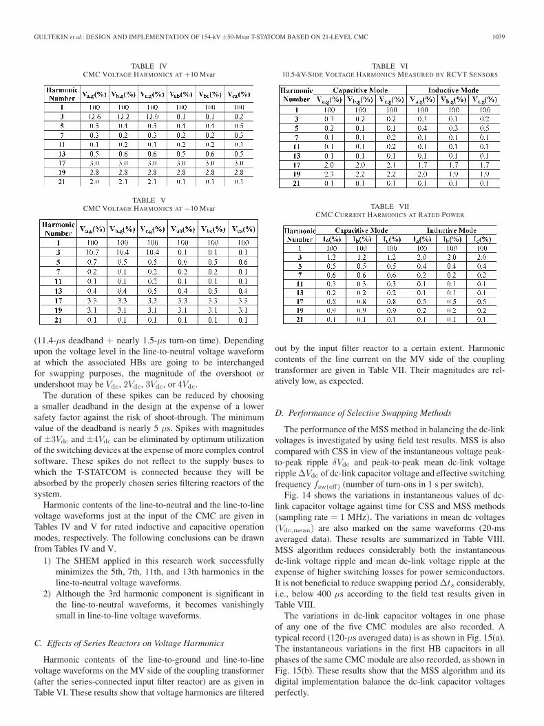
Harmonic contents of the line-to-neutral and the line-to-linevoltage waveforms just at the input of the CMC are given inTables IV and V for rated inductive and capacitive operationmodes, respectively. The following conclusions can be drawnfrom Tables IV and V.
1) The SHEM applied in this research work successfullyminimizes the 5th, 7th, 11th, and 13th harmonics in theline-to-neutral voltage waveforms.
2) Although the 3rd harmonic component is significant inthe line-to-neutral waveforms, it becomes vanishinglysmall in line-to-line voltage waveforms.
C. Effects of Series Reactors on Voltage Harmonics
Harmonic contents of the line-to-ground and line-to-linevoltage waveforms on the MV side of the coupling transformer(after the series-connected input filter reactor) are as given inTable VI. These results show that voltage harmonics are filtered
TABLE VI10.5-kV-SIDE VOLTAGE HARMONICS MEASURED BY RCVT SENSORS
TABLE VIICMC CURRENT HARMONICS AT RATED POWER
out by the input filter reactor to a certain extent. Harmoniccontents of the line current on the MV side of the couplingtransformer are given in Table VII. Their magnitudes are rel-atively low, as expected.
D. Performance of Selective Swapping Methods
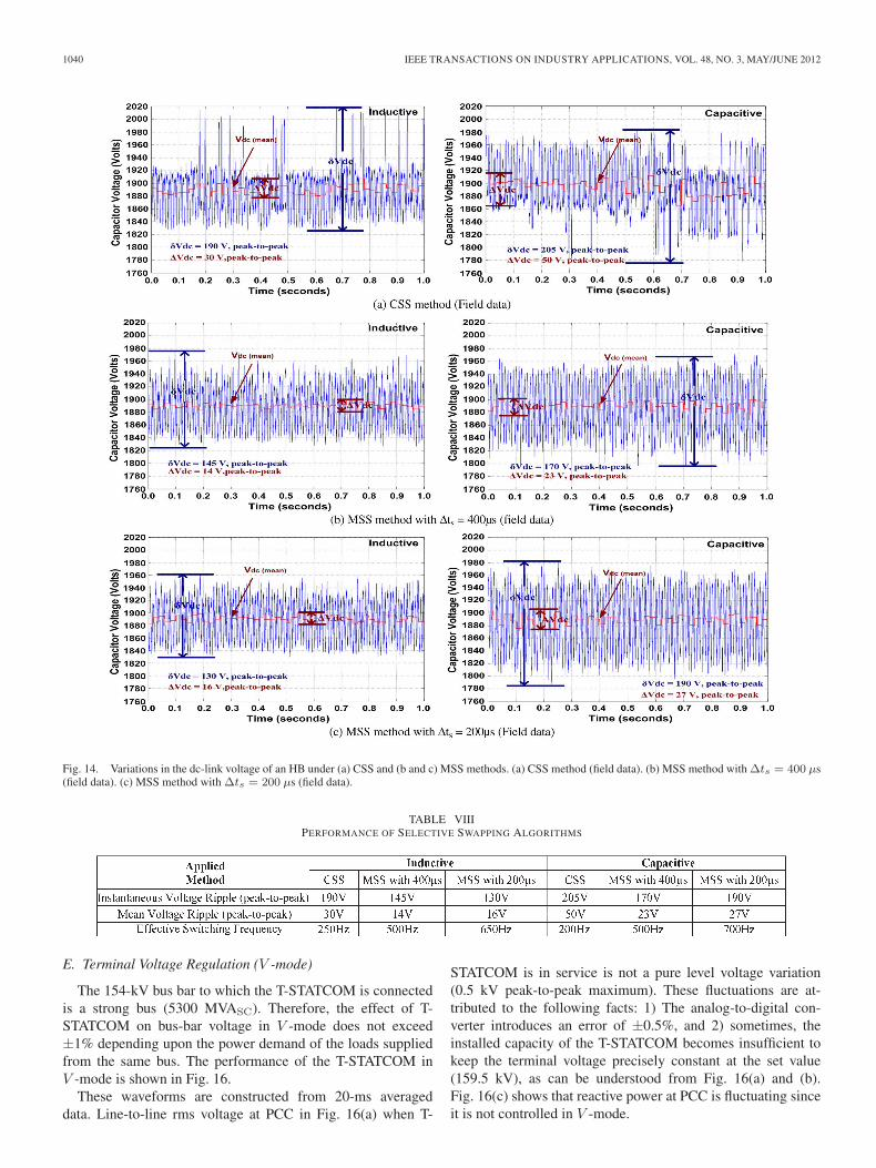
The performance of the MSS method in balancing the dc-linkvoltages is investigated by using field test results. MSS is alsocompared with CSS in view of the instantaneous voltage peak-to-peak ripple δVdc and peak-to-peak mean dc-link voltageripple ΔVdc of dc-link capacitor voltage and effective switchingfrequency fsw(eff) (number of turn-ons in 1 s per switch).
Fig. 14 shows the variations in instantaneous values of dc-link capacitor voltage against time for CSS and MSS methods(sampling rate = 1 MHz). The variations in mean dc voltages(Vdc,mean) are also marked on the same waveforms (20-msaveraged data). These results are summarized in Table VIII.MSS algorithm reduces considerably both the instantaneousdc-link voltage ripple and mean dc-link voltage ripple at theexpense of higher switching losses for power semiconductors.It is not beneficial to reduce swapping period Δts considerably,i.e., below 400 μs according to the field test results given inTable VIII.
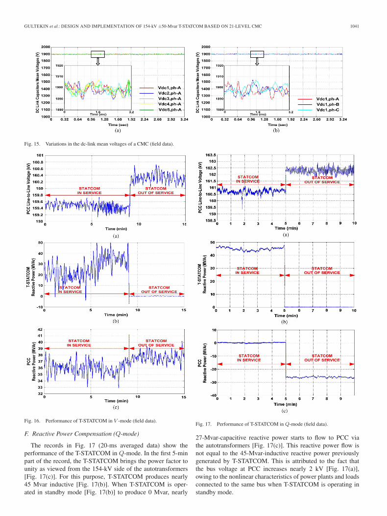
The variations in dc-link capacitor voltages in one phaseof any one of the five CMC modules are also recorded. Atypical record (120-μs averaged data) is as shown in Fig. 15(a).The instantaneous variations in the first HB capacitors in allphases of the same CMC module are also recorded, as shown inFig. 15(b). These results show that the MSS algorithm and itsdigital implementation balance the dc-link capacitor voltagesperfectly.
1040 IEEE TRANSACTIONS ON INDUSTRY APPLICATIONS, VOL. 48, NO. 3, MAY/JUNE 2012
Fig. 14. Variations in the dc-link voltage of an HB under (a) CSS and (b and c) MSS methods. (a) CSS method (field data). (b) MSS method with Δts = 400 μs(field data). (c) MSS method with Δts = 200 μs (field data).
TABLE VIIIPERFORMANCE OF SELECTIVE SWAPPING ALGORITHMS
E. Terminal Voltage Regulation (V -mode)
The 154-kV bus bar to which the T-STATCOM is connectedis a strong bus (5300 MVASC). Therefore, the effect of T-STATCOM on bus-bar voltage in V -mode does not exceed±1% depending upon the power demand of the loads suppliedfrom the same bus. The performance of the T-STATCOM inV -mode is shown in Fig. 16.
These waveforms are constructed from 20-ms averageddata. Line-to-line rms voltage at PCC in Fig. 16(a) when T-
STATCOM is in service is not a pure level voltage variation(0.5 kV peak-to-peak maximum). These fluctuations are at-tributed to the following facts: 1) The analog-to-digital con-verter introduces an error of ±0.5%, and 2) sometimes, theinstalled capacity of the T-STATCOM becomes insufficient tokeep the terminal voltage precisely constant at the set value(159.5 kV), as can be understood from Fig. 16(a) and (b).Fig. 16(c) shows that reactive power at PCC is fluctuating sinceit is not controlled in V -mode.
GULTEKIN et al.: DESIGN AND IMPLEMENTATION OF 154-kV ±50-Mvar T-STATCOM BASED ON 21-LEVEL CMC 1041
Fig. 15. Variations in the dc-link mean voltages of a CMC (field data).
Fig. 16. Performance of T-STATCOM in V -mode (field data).
F. Reactive Power Compensation (Q-mode)
The records in Fig. 17 (20-ms averaged data) show theperformance of the T-STATCOM in Q-mode. In the first 5-minpart of the record, the T-STATCOM brings the power factor tounity as viewed from the 154-kV side of the autotransformers[Fig. 17(c)]. For this purpose, T-STATCOM produces nearly45 Mvar inductive [Fig. 17(b)]. When T-STATCOM is oper-ated in standby mode [Fig. 17(b)] to produce 0 Mvar, nearly
Fig. 17. Performance of T-STATCOM in Q-mode (field data).
27-Mvar-capacitive reactive power starts to flow to PCC viathe autotransformers [Fig. 17(c)]. This reactive power flow isnot equal to the 45-Mvar-inductive reactive power previouslygenerated by T-STATCOM. This is attributed to the fact thatthe bus voltage at PCC increases nearly 2 kV [Fig. 17(a)],owing to the nonlinear characteristics of power plants and loadsconnected to the same bus when T-STATCOM is operating instandby mode.
1042 IEEE TRANSACTIONS ON INDUSTRY APPLICATIONS, VOL. 48, NO. 3, MAY/JUNE 2012
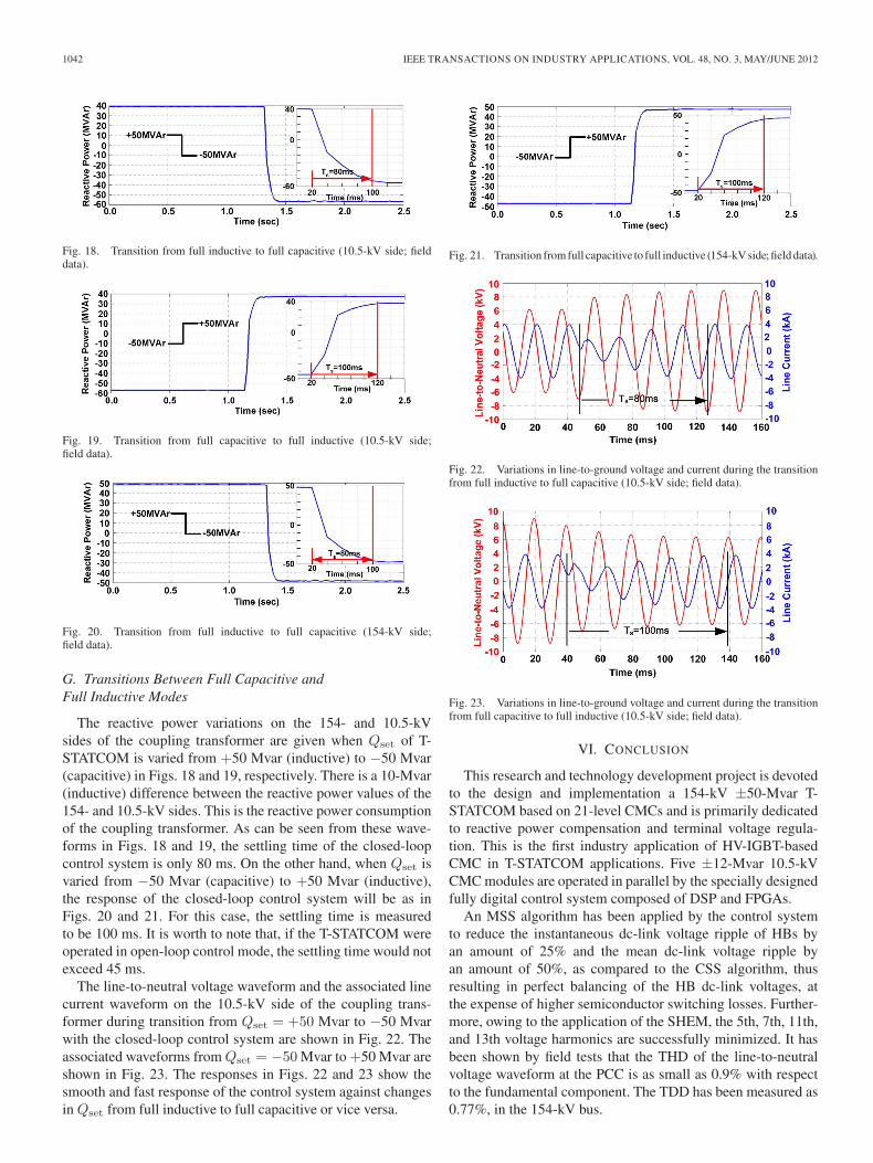
Fig. 18. Transition from full inductive to full capacitive (10.5-kV side; fielddata).
Fig. 19. Transition from full capacitive to full inductive (10.5-kV side;field data).
Fig. 20. Transition from full inductive to full capacitive (154-kV side;field data).
G. Transitions Between Full Capacitive andFull Inductive Modes
The reactive power variations on the 154- and 10.5-kVsides of the coupling transformer are given when Qset of T-STATCOM is varied from +50 Mvar (inductive) to −50 Mvar(capacitive) in Figs. 18 and 19, respectively. There is a 10-Mvar(inductive) difference between the reactive power values of the154- and 10.5-kV sides. This is the reactive power consumptionof the coupling transformer. As can be seen from these wave-forms in Figs. 18 and 19, the settling time of the closed-loopcontrol system is only 80 ms. On the other hand, when Qset isvaried from −50 Mvar (capacitive) to +50 Mvar (inductive),the response of the closed-loop control system will be as inFigs. 20 and 21. For this case, the settling time is measuredto be 100 ms. It is worth to note that, if the T-STATCOM wereoperated in open-loop control mode, the settling time would notexceed 45 ms.
The line-to-neutral voltage waveform and the associated linecurrent waveform on the 10.5-kV side of the coupling trans-former during transition from Qset = +50 Mvar to −50 Mvarwith the closed-loop control system are shown in Fig. 22. Theassociated waveforms from Qset = −50 Mvar to +50 Mvar areshown in Fig. 23. The responses in Figs. 22 and 23 show thesmooth and fast response of the control system against changesin Qset from full inductive to full capacitive or vice versa.
Fig. 21. Transition from full capacitive to full inductive (154-kV side; field data).
Fig. 22. Variations in line-to-ground voltage and current during the transitionfrom full inductive to full capacitive (10.5-kV side; field data).
Fig. 23. Variations in line-to-ground voltage and current during the transitionfrom full capacitive to full inductive (10.5-kV side; field data).
VI. CONCLUSION
This research and technology development project is devotedto the design and implementation a 154-kV ±50-Mvar T-STATCOM based on 21-level CMCs and is primarily dedicatedto reactive power compensation and terminal voltage regula-tion. This is the first industry application of HV-IGBT-basedCMC in T-STATCOM applications. Five ±12-Mvar 10.5-kVCMC modules are operated in parallel by the specially designedfully digital control system composed of DSP and FPGAs.
An MSS algorithm has been applied by the control systemto reduce the instantaneous dc-link voltage ripple of HBs byan amount of 25% and the mean dc-link voltage ripple byan amount of 50%, as compared to the CSS algorithm, thusresulting in perfect balancing of the HB dc-link voltages, atthe expense of higher semiconductor switching losses. Further-more, owing to the application of the SHEM, the 5th, 7th, 11th,and 13th voltage harmonics are successfully minimized. It hasbeen shown by field tests that the THD of the line-to-neutralvoltage waveform at the PCC is as small as 0.9% with respectto the fundamental component. The TDD has been measured as0.77%, in the 154-kV bus.
GULTEKIN et al.: DESIGN AND IMPLEMENTATION OF 154-kV ±50-Mvar T-STATCOM BASED ON 21-LEVEL CMC 1043
The transient response of the developed system is also foundto be quite satisfactory. The settling times of the T-STATCOMat full load from inductive mode to capacitive mode and viceversa have been recorded as 80 and 100 ms, respectively, inthe field, with a transient-free transition between modes. Themodularity of HBs for easy replacement in the case of a failure,and the mobility and flexibility of the overall T-STATCOM foreasy relocation when necessary are being further advantages ofthe developed system.
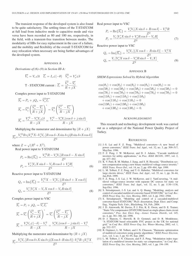
APPENDIX A
Derivations of (6)–(9) in Section III-A:
−→Vc = Vc�0 −→
Ic = Ic�(−θ)−→V ′
s = V ′s�δ
T - STATCOM current : −→Ic =−→V ′
s −−→Vc
R + jX.
Complex power input to T-STATCOM
−→Ss = Ps + jQs =
−→V ′
s−→Ic
∗
−→Ss =
−→V ′
s
(−→V ′
s −−→Vc
R + jX
)∗
=−→V ′
s
(−→V ′
s
∗− −→
Vc∗
R − jX
)
−→Ss =
V ′2s − V ′
sVc�δ
R − jX=
V ′2s − V ′
sVc(cos δ + j sin δ)R − jX
.
Multiplying the numerator and denominator by (R + jX)
−→Ss=
V ′2s R+jV ′2
s X−V ′sVc [R cos δ−Xsin δ+j(R sin δ+Xcos δ)]
Z2
where Z =√
(R2 + X2).Real power input to T-STATCOM
Ps = Re{−→Ss} =V ′2
s R − V ′sVc[R cos δ − X sin δ]
Z2
Ps =V ′
s [VcX sin δ − VcR cos δ + V ′sR]
Z2. (6)
Reactive power input to T-STATCOM
Qs = Im{−→Ss} =V ′2
s X − V ′sVc [(R sin δ + X cos δ)]
Z2
Qs =V ′
s [V ′sX − VcX cos δ − VcR sin δ]
Z2. (8)
Complex power input to VSC
−→Sc = Pc + jQc = −→
Vc−→Ic
∗
−→Sc =−→
Vc
(−→V ′
s −−→Vc
R + jX
)∗
= −→Vc
(−→V ′
s
∗− −→
Vc∗
R − jX
)
−→Sc =
V ′sVc�(−δ) − V 2
c
R − jX=
V ′sVc(cos δ − j sin δ) − V 2
c
R − jX.
Multiplying the numerator and denominator by (R + jX)
−→Sc=
V ′sVc [R cos δ+X sin δ+j(Xcos δ−R sin δ)]−V 2
c R−jV 2c X
Z2.
Real power input to VSC
Pc = Re{−→Sc} =V ′
sVc[X sin δ + R cos δ] − V 2c R
Z2
Pc =Vc [V ′
sX sin δ + V ′sR cos δ − VcR]
Z2. (7)
Reactive power input to VSC
Qc = Im{−→Sc} =V ′
sVc [(X cos δ − R sin δ)] − V 2c X
Z2
Qc =Vc [V ′
sX cos δ − V ′sR sin δ − VcX]
Z2. (9)
APPENDIX B
SHEM Expressions Solved by Hybrid Algorithm
cos(θ1) + cos(θ2) + cos(θ3) + cos(θ4) + cos(θ5) = mcos(5θ1) + cos(5θ2) + cos(5θ3) + cos(5θ4) + cos(5θ5) = 0cos(7θ1) + cos(7θ2) + cos(7θ3) + cos(7θ4) + cos(7θ5) = 0cos(11θ1) + cos(11θ2) + cos(11θ3)
+ cos(11θ4) + cos(11θ5) = 0cos(13θ1) + cos(13θ2) + cos(13θ3)
+ cos(13θ4) + cos(13θ5) = 0.
ACKNOWLEDGMENT
This research and technology development work was carriedout as a subproject of the National Power Quality Project ofTurkey.
REFERENCES
[1] J.-S. Lai and F. Z. Peng, “Multilevel converters—A new breed ofpower converters,” IEEE Trans. Ind. Appl., vol. 32, no. 3, pp. 509–517,May/Jun. 1996.
[2] F. Z. Peng, J. W. McKeever, and D. J. Adams, “Cascade multilevelinverters for utility applications,” in Proc. IEEE IECON, 1997, vol. 2,pp. 437–442.
[3] K. V. Patil, R. M. Mathur, J. Jiang, and S. H. Hosseini, “Distribution sys-tem compensation using a new binary multilevel voltage source inverter,”IEEE Trans. Power Del., vol. 14, no. 2, pp. 459–464, Apr. 1999.
[4] L. M. Tolbert, F. Z. Peng, and T. G. Habetler, “Multilevel converters forlarge electric drives,” IEEE Trans. Ind. Appl., vol. 35, no. 1, pp. 36–44,Jan./Feb. 1999.
[5] F. Z. Peng, J.-S. Lai, J. W. McKeever, and J. VanCoevering, “A mul-tilevel voltage-source inverter with separate DC sources for static varconverters,” IEEE Trans. Ind. Appl., vol. 32, no. 5, pp. 1130–1138,Sep./Oct. 1996.
[6] S. Sirisukprasert, J.-S. Lai, and A. Q. Huang, “Modeling, analysis andcontrol of cascaded multilevel converter based STATCOM,” in Conf. Rec.IEEE Power Eng. Soc. Gen. Meeting, 2003, vol. 4, pp. 2561–2568.
[7] S. Sirisukprasert, “Modeling and control of a cascaded-multilevelconverter-based STATCOM,” Ph.D. dissertation, Dept. Elect. and Comp.Eng., Virginia Tech. Univ., Blacksburg, VA, Feb., 2004.
[8] J. D. Ainsworth, M. Davies, P. J. Fitz, K. E. Owen, and D. E. Trainer,“Static VAr compensator (STATCOM) based on single-phase chain circuitconverters,” Proc. Inst. Elect. Eng.—Gener. Transm. Distrib., vol. 145,no. 4, pp. 381–386, Jul. 1998.
[9] D. J. Hanson, C. Horwill, B. D. Gemmel, and D. R. Monkhouse,“A STATCOM based relocatable SVC project in the UK for nationalgrid,” in Conf. Rec. IEEE Power Eng. Soc. Winter Meeting, 2002, vol. 1,pp. 532–537.
[10] B. Ozpineci, L. M. Tolbert, and J. N. Chiasson, “Harmonic optimizationof multilevel converters using genetic algorithms,” IEEE Power Electron.Lett., vol. 3, no. 3, pp. 92–95, Sep. 2005.
[11] L. M. Tolbert, J. N. Chiasson, and F. Z. Peng, “Modulation index regu-lation of a multilevel inverter for static var compensation,” in Conf. Rec.IEEE Power Eng. Soc. Gen. Meeting, 2003, vol. 1, pp. 194–199.
1044 IEEE TRANSACTIONS ON INDUSTRY APPLICATIONS, VOL. 48, NO. 3, MAY/JUNE 2012
Burhan Gultekin (S’03) received the B.Sc. andM.Sc. degrees in electrical and electronics engineer-ing from Middle East Technical University, Ankara,Turkey, in 2000 and 2003, respectively, where he iscurrently working toward the Ph.D. degree.
He is currently the Head of the Power ElectronicsDepartment, Space Technologies Research Institute,The Scientific and Technological Research Councilof Turkey (TUBITAK), Ankara, where he is also aChief Senior Researcher. His areas of research arereactive power compensation systems, system design
and protection, and power quality issues.Mr. Gultekin was a recipient of the “Outstanding Paper Award” from the
Metals Industry Committee of the IEEE Industry Applications Society in 2009.
Cem Ozgur Gerçek (S’04) received the B.Sc. andM.Sc. degrees in electrical and electronics engineer-ing from Middle East Technical University (METU),Ankara, Turkey, in 2004 and 2007, respectively,where he is currently working toward the Ph.D.degree in control issues of transmission static syn-chronous compensator systems.
Between 2004 and 2006, he was a Research As-sistant with the Electrical and Electronics Engineer-ing Department, METU. He is currently a SeniorResearcher with the Power Electronics Department,
Space Technologies Research Institute, The Scientific and Technological Re-search Council of Turkey (TUBITAK), Ankara. His areas of research includeflexible ac transmission systems devices, reactive power compensation systems,and power quality issues.
Tevhid Atalik (S’10) received the B.Sc. degreein electronics engineering from Uludag University,Bursa, Turkey, in 2003, and the M.Sc. degree in elec-trical and electronics engineering from HacettepeUniversity, Ankara, Turkey, in 2007. He is currentlyworking toward the Ph.D. degree in electrical engi-neering at Baskent University, Ankara.
He is also currently a Senior Researcher with thePower Electronics Department, Space TechnologiesResearch Institute, The Scientific and TechnologicalResearch Council of Turkey (TUBITAK), Ankara.
His areas of research include analog and digital control circuit design, instru-mentation, and power quality.
Mr. Atalik was a recipient of the “Outstanding Paper Award” from the MetalsIndustry Committee of the IEEE Industry Applications Society in 2009.
Mustafa Deniz (S’10) received the B.Sc. and M.Sc.degrees in electrical and electronics engineeringfrom Middle East Technical University, Ankara,Turkey, in 2006 and 2009, respectively, where heis currently working toward the Ph.D. degree in thedesign and implementation of grid-connected photo-voltaic systems.
He is also currently a Senior Researcher with thePower Electronics Department, Space TechnologiesResearch Institute, The Scientific and TechnologicalResearch Council of Turkey (TUBITAK), Ankara.
His current areas of research include digital control of power converters,photovoltaic inverters, and motor drives.
Nazan Biçer received the B.Sc. and M.Sc. degreesin electrical and electronics engineering from MiddleEast Technical University, Ankara, Turkey, in 2005and 2010, respectively.
She is currently a Researcher with the PowerSystems Department, Space Technologies ResearchInstitute, The Scientific and Technological ResearchCouncil of Turkey (TUBITAK), Ankara. Her areasof interest are power electronics and power systems.
Muammer Ermis (M’99) received the B.Sc., M.Sc.,and Ph.D. degrees in electrical engineering fromMiddle East Technical University (METU), Ankara,Turkey, in 1972, 1976, and 1982, respectively, andthe M.B.A. degree in production management fromAnkara Academy of Economic and Commercial Sci-ences, Ankara, in 1974.
Currently, he is a Professor of electrical engineer-ing in the Department of Electrical and ElectronicsEngineering, METU.
Dr. Ermis was the recipient of The Overseas Pre-mium Paper Award from the Institution of Electrical Engineers, U.K., in1992, and the 2000 Committee Prize Paper Award from the Power SystemsEngineering Committee of the IEEE Industry Applications Society. He was alsothe recipient of the 2003 IEEE Power Engineering Society Chapter OutstandingEngineer Award and the Outstanding Paper Award from the Metals IndustryCommittee of the IEEE Industry Applications Society in 2009.
Kemal Nadir Kose received the B.Sc. degree inelectrical and electronics engineering from MiddleEast Technical University, Ankara, Turkey, in 1993,and the M.Sc. degree from Hacettepe University,Ankara, in 2001.
He was a Chief Senior Researcher with the PowerElectronics Department, Space Technologies Re-search Institute, The Scientific and TechnologicalResearch Council of Turkey (TUBITAK), Ankara.He is currently an Electrical Engineer with MagellanPower Systems, Perth, Australia.
Cezmi Ermis received the B.Arch. and M.Arch.degrees in architecture from Middle East Techni-cal University, Ankara, Turkey, in 1980 and 1983,respectively.
From 1980 to 1985, he worked for architecturaldesign studios as a Building and Interior Designer. In1986, he founded his own architectural rendering andillustration studio and served several private compa-nies to present their buildings and plant designs until2000. He is currently a Chief Senior Researcher inthe Power Electronics Department, TUBITAK Uzay
Research Institute, Ankara, working on the design of industrial structures andbuildings specifically for the application of power electronics to industry.
Mr. Ermis received six prizes in national architectural competitions and eightprizes in international and national cartoon contests.
Erkan Koç received the B.Sc. and M.Sc. degrees inelectrical and electronics engineering from MiddleEast Technical University, Ankara, Turkey, in 2005and 2010, respectively.
Between 2005 and 2006, he was a System Engi-neer with ELIMKO, Ankara. He is currently a SeniorResearcher with the Power Electronics Department,Space Technologies Research Institute, The Scien-tific and Technological Research Council of Turkey(TUBITAK), Ankara. His areas of research includerenewable energy and supervisory control and data
acquisition systems.
GULTEKIN et al.: DESIGN AND IMPLEMENTATION OF 154-kV ±50-Mvar T-STATCOM BASED ON 21-LEVEL CMC 1045
Isik Çadirci (M’98) received the B.Sc., M.Sc.,and Ph.D. degrees from Middle East TechnicalUniversity, Ankara, Turkey, in 1987, 1988, and1994, respectively, all in electrical and electronicsengineering.
She is currently a Professor of electrical engineer-ing at Hacettepe University, Ankara. Her areas ofinterest include power quality, electric motor drives,and switch-mode power supplies.
Dr. Çadırcı was a recipient of the Committee PrizePaper Award from the Power Systems Engineering
Committee of the IEEE Industry Applications Society in 2000; the IEEEIndustry Applications Magazine Prize Paper Award, Third Prize, in 2007; andthe Outstanding Paper Award from the Metals Industry Committee of the IEEEIndustry Applications Society in 2009.
Adnan Açik received the B.Sc. and M.Sc. degreesin electrical and electronics engineering from MiddleEast Technical University, Ankara, Turkey, in 1995and 1998, respectively.
He was a Chief Senior Researcher with the PowerElectronics Department, Space Technologies Re-search Institute, The Scientific and TechnologicalResearch Council of Turkey (TUBITAK), Ankara.He is currently the Engineering Director of EndoksEnergy Systems, Ankara. His main areas of researchare power quality and switch-mode power supplies.
Yener Akkaya received the B.Sc. degree in electricalengineering from the Faculty of Electrical and Elec-tronic Engineering, Istanbul Technical University,Istanbul, Turkey, in 1989. He also completed thePublic Administration Master Program at the Turkeyand Middle East Public Administration Institute(TODAIE), Ankara, Turkey, in 1997.
Since 1989, he has been with the Turkish Electric-ity Transmission Company (TEIAS), Ankara, wherehe was the Director of the Research and Develop-ment Department from 2003 to 2011 and has been
the Director of the Middle Anatolia Region Maintenance and Operation De-partment since 2011. His current interests are power quality and transmissionsystem planning, operation, and maintenance.
Hikmet Toygar received the B.Arch. degree fromGazi University, Ankara, Turkey, in 1986.
He is currently the Vice Director of the Mainte-nance and Operation Department, Turkish ElectricityTransmission Company (TEIAS), Ankara. His ex-pertise is in the field of design, construction, andoperation of high-voltage transmission lines.
Semih Bideci received the B.Sc. degree in en-ergy engineering from the Electrical EngineeringDepartment, Istanbul Technical University, Istanbul,Turkey, in 1975.
He is currently a Chief Engineer with the Admin-istration and Maintenance Department, Turkish Elec-tricity Transmission Company (TEIAS), Ankara,Turkey. His expertise is in the field of design, con-struction, and operation of high-voltage transmissionlines.


