Embed Size (px)
Citation preview
Pure Appl. Chem., Vol. 73, No. 12, pp. 1819–1837, 2001.© 2001 IUPAC
1819
Electrochemical technology for environmentaltreatment and clean energy conversion*
F. C. Walsh
Electrochemical Engineering Group, Department of Chemical Engineering,University of Bath, Claverton Down, Bath BA2 7AY, UK
Abstract: The applications of electrochemical technology in environmental treatment, mate-rials recycling, and clean synthesis are briefly reviewed. The diversity of these applicationsis shown by the number of industrial sectors involved. The scale of operation ranges frommicroelectrodes to large industrial cell rooms. The features of electrochemical processes aresummarized.
Available and developing electrode designs are considered and illustrated by examplesincluding the regeneration of chromic acid electroplating baths, metal ion removal by porous,3-dimensional cathodes, rotating cylinder electrodes (RCEs), and a reticulated vitreous car-bon (RVC) RCE. The use of performance indicators based on mass transport, electrode area,and power consumption is emphasized.
Electrochemical reactors for energy conversion are considered, with an emphasis onload-leveling and proton-exchange membrane (PEM) (hydrogen–oxygen) fuel cells. Ion-exchange membranes play an essential role in such reactors, and the variation of electricalresistance vs. membrane thickness is described for a series of extruded, Nafion® 1100 EWmaterials. The characterization of high-surface-area, platinized Nafion surfaces is also con-sidered. The development of modular, filter-press cells as redox flow cells in electrical load-leveling applications is concisely described.
Trends in electrode, membrane, and reactor design are highlighted, and the challengesfor the development of improved reactors for environmental treatment are noted.
INTRODUCTION
There are increasing economic, social, legal, and environmental pressures to utilize the “best availabletechnology” not entailing excessive cost and to aspire to “performance without pollution”, i.e., “zeropollution processing”. Electrochemical technology has an important role to play as part of an integrat-ed approach to the avoidance of pollution, monitoring of pollution and process efficiency, cleaner pro-cessing, and modern techniques for electrical energy storage and conversion.
Electrochemical technology [1–5] continues to make many contributions to environmental treat-ment, recycling, and monitoring [6–11]. As shown by the examples in Table 1, electrochemistry canplay many roles in clean technology and pollution control:
a) the avoidance of polluting reagents in materials synthesis, such as zinc powder for organic reduc-tions, by the use of direct electron transfer
b) the monitoring of pollutant and reagent levels in process streams, rinse sections, effluents, andgaseous emissions
*An issue of reviews and research papers based on presentations made at the IUPAC/ICSU Workshop on Electrochemistry andInterfacial Chemistry in Environmental Clean-up and Green Chemical Processes, Coimbra, Portugal, 6–7 April, 2001.
c) the treatment of water by electrochemically generated species, such as chlorination of swimmingpools and sterilization of medical instruments using a powerful cocktail of oxidizing reagents in“superoxidized” water
d) the removal of environmental contaminants, such as metal ions and organics from industrialprocess streams
e) the clean conversion of chemical to electrochemical energy using fuel cell and photovoltaicdevices
Continued developments in our understanding and documentation of the electrodes and mem-branes [12,13] and electrochemical reactor design [14,15] together with increasing industrial experienceof their use [16,17] are resulting in a more widespread acceptability of electrochemical technology andits features (Table 2).
F. C. WALSH
© 2001 IUPAC, Pure and Applied Chemistry 73, 1819–1837
1820
Table 1 The scope for electrochemical technology in environmental treatment.
• Avoidance of pollutionclean electrosynthesis
• Recycling of valuable materialsprecious metal deposition
• Remediation of polluted sitessoil remediation by electrodialysis
• Monitoring and sensorsin the gas and liquid phase
• Efficient energy conversionfuel cells and redox flow cells
• Avoidance of corrosionchoice of materials/protective coatings
• Removal of contaminantsmetal ion, organics, and inorganics removal from water and process liquors
• Disinfection of waterchlorination, peroxy species, or ozone
Table 2 The advantages and limitations of electrochemical technology.
The Many Advantages • Electrons are clean reagents (at least at their source of supply).• Effective control of the electron transfer rate (current density).• Measurement of reaction conditions (current density and electrode potential).• The process can be turned on and off via the current.• Can often use benign (e.g., ambient) conditions of temperature and pressure.Possible Limitations• Many research workers have little industrial/large-scale experience of electrochemical technology,
hindering technology transfer.• Some industrial sectors have limited knowledge or experience of electrochemical technology.• There are relatively few “showcases” for the technology.• There is a shortage of experienced electrochemical engineers.• Chemical reactions, corrosion, adsorption, etc., at electrode surfaces can cause complications.• Damage to electrodes and membranes via, e.g., corrosion and fouling, can restrict performance and
longevity.
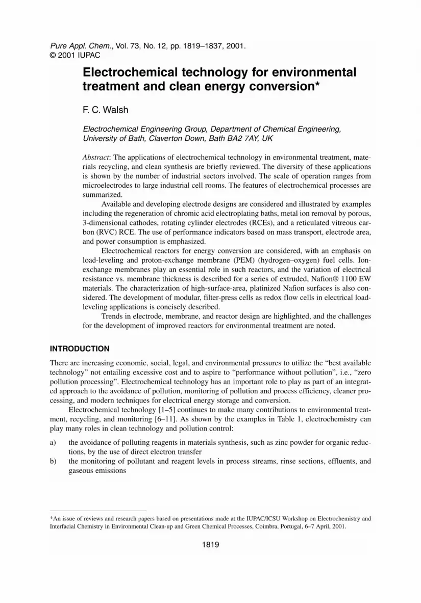
The scale of electrochemical technology is diverse and ranges from single microelectrode probesof perhaps 10–10 m2 through to large parallel plate cell houses of total electrode area <104 m2 in chlor-alkali industry and load-leveling redox flow cell developments [5]. The total cell current can vary from10–9 A up to >106 A (Fig. 1). This range continues to expand, particularly at the lower end of the scaleof current and surface area, due to development in microelectrode probes for chemical analysis andscanning probe microscopies for advanced imaging of surfaces. The present paper considers examplesof electrochemical reactors that have been used in applications in the general range 0.0001 to 1000 m2
(involving currents of <10–2 A to >100 kA. The emphasis is on the removal of contaminants from (andthe regeneration of) aqueous solutions, together with improvements in electrode and membranes usedfor energy conversion and storage applications. In the case of analytical applications of environmentalelectrochemistry, the reader is directed to a review [17] and to other contributions in this special issue.
ELECTRODE AND REACTOR DESIGN
Factors affecting the selection of an electrochemical reactor
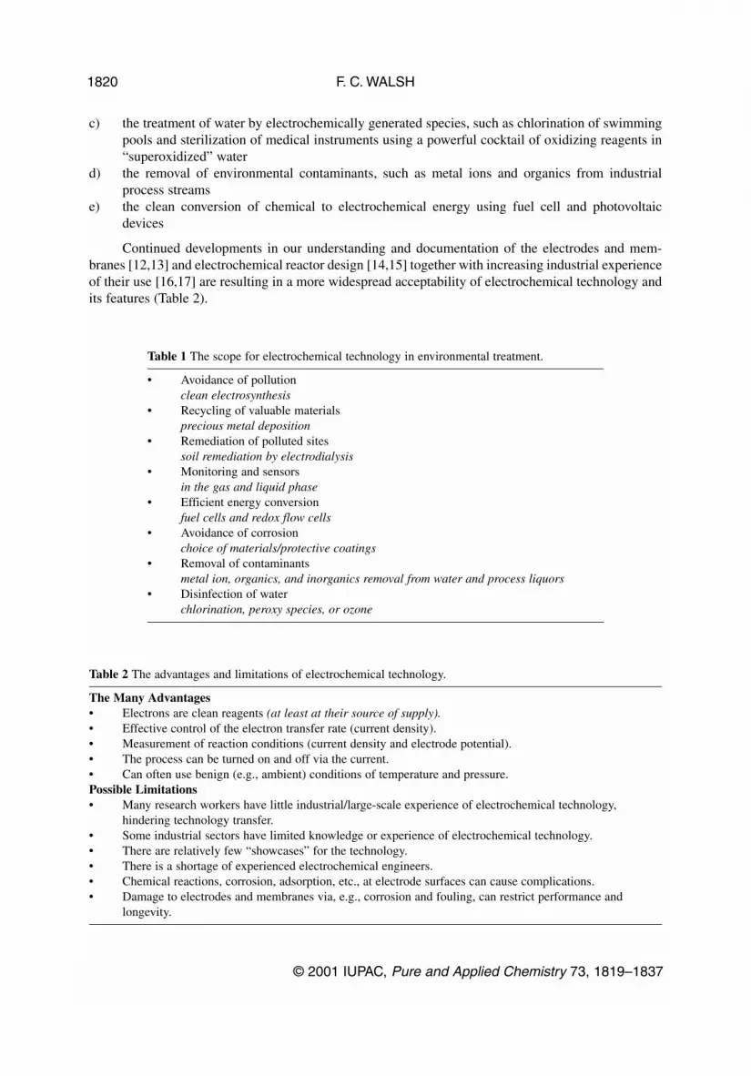
It is important to design (or select) an electrochemical reactor for a specific process, and it is clear thatreactors for energy conversion and electrochemical synthesis will have different drivers to those used inthe destruction of electrolyte-based contaminants. Figure 2 shows some of the decision processesinvolved in the selection of electrochemical reactor design. Adequate attention must be paid to the formof the electrode, its geometry and motion, together with the need for cell division or a thin electrolytegap [18]. The form of the reactants and products and the mode of operation (batch or continuous) arealso important design factors [1,2].
Desirable factors in reactor design (and their implications) include [18]:
a) moderate costs (low-cost components, a low cell voltage, and a small pressure drop over the reac-tor)
b) convenience and reliability in operation (designed for facile installation, maintenance, and mon-itoring)
c) appropriate reaction engineering (uniform and appropriate values of current density, electrodepotential, mass transport, and flow)
d) simplicity and versatility (in an elegant design, which is attractive to end users)
© 2001 IUPAC, Pure and Applied Chemistry 73, 1819–1837
Electrochemical technology for environmental treatment 1821
Fig. 1 The scale of electrochemical technology: beyond nanoamperes to megaamperes.
Problem areas for electrode technology and stability may be listed as:
a) activity and surface area changes due to catalysis, blockage, and potential-distributionb) adsorption/desorption of reactant, product, intermediates, contaminantsc) film formation/removal via, e.g., passivation or polymerizationd) phase transformation, e.g., solid–solid, intercalation, dehydration
Ion-exchange membranes [13] can play a critical role in electrochemical reactors; their advan-tages and drawbacks are summarized in Table 3, while Table 4 provides a list of the essential featuresof electrodes and membranes in electrochemical reactors. The many reactor designs described in thescientific and engineering literature can be distilled down to a very few examples of industrially impor-tant reactors on the pilot and full commercial scale.
F. C. WALSH
© 2001 IUPAC, Pure and Applied Chemistry 73, 1819–1837
1822
Fig. 2 Decisions during the process of selecting an electrochemical reactor. The route shown in boldface indicatesthe selection of an undivided, 2-dimensional bipolar filter-press cell. (More specialized reactors are required formany applications such as metal ion removal from dilute solution).
Table 3 The essential features required from electrodes and ion-exchange membranes inelectrochemical reactors
• high surface area electrodes (Ae)• high mass transport to electrodes (high km)• good electrocatalysis at the electrode surface (high jo desired reaction)• acceptable cost, lifetime, and practicality of electrodes and membranes• high conductivity and ease of connection to electrodes• low potential drop over electrodes and membranes• membranes that are selective to a particular ion• low solvent transport rate through membranes
Important factors in reactor performance
There are many compromises during the process of reactor design/selection in order to accommodatethe large number of factors acting as drivers:
a) uniform current density distributionb) uniform electrode potential distributionc) high mass transport ratesd) ability to handle solid, liquid, or gaseous products.e) the form of the product and the ease of product extractionf) simplicity of design, installation, and maintenanceg) availability of electrode and membrane materialsh) capital and running costsi) integration with other process needs
The energy efficiency of a reactor depends on the cell voltage, which can be expressed as a num-ber of voltage components:
where the terms on the right-hand side represent the thermodynamic equilibrium cell voltage, the sumof the overpotentials at each electrode, and the sum of all ohmic drops in the reactor due to current (I)flow through resistances (R). It is important to minimize overpotential and ohmic components of volt-age in order to maximize energy efficiency. Appropriate strategies include the use of conductive, cat-alytic electrodes and membranes, the use of small inter-electrode (or membrane-electrode) gaps, andcareful choice of the counter electrode chemistry to minimize the equilibrium cell voltage term.
It is common to have a low reactant concentration (c) in environmental treatment and to require com-pact treatment units in a restricted space. Under such conditions, the rate of contaminant removal in a Z elec-tron change process is often mass transport limited, and a high-performance reactor needs to have a high masstransport coefficient (km) and enhanced electrode area (A) in order to achieve a high limiting current (IL):
(1)
High mass transport rates can be achieved by the use of electrode movement, including reciprocationof planar electrodes and moving bed electrodes or rotating cylinder reactors while high surface area perunit volume can be achieved by the use of porous, 3-dimensional electrodes [19].
© 2001 IUPAC, Pure and Applied Chemistry 73, 1819–1837
Electrochemical technology for environmental treatment 1823
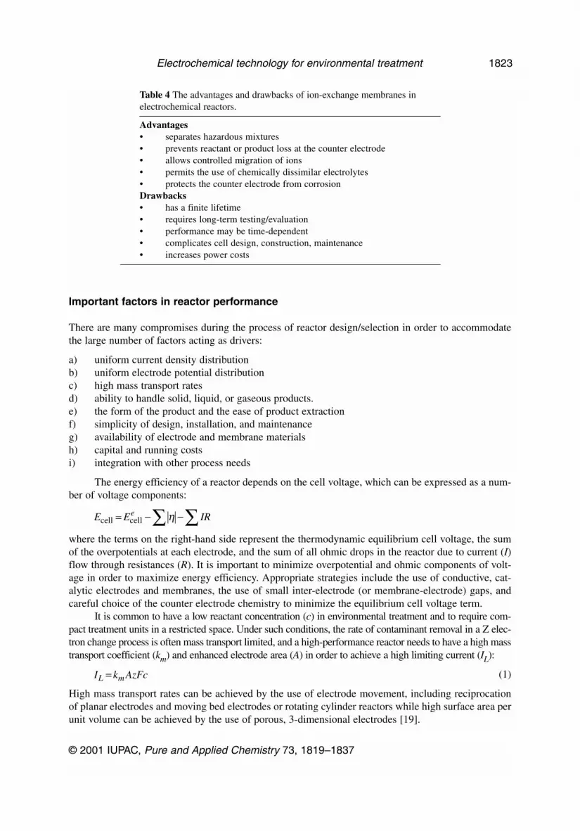
Table 4 The advantages and drawbacks of ion-exchange membranes inelectrochemical reactors.
Advantages• separates hazardous mixtures• prevents reactant or product loss at the counter electrode• allows controlled migration of ions• permits the use of chemically dissimilar electrolytes• protects the counter electrode from corrosionDrawbacks• has a finite lifetime• requires long-term testing/evaluation• performance may be time-dependent• complicates cell design, construction, maintenance• increases power costs
E E IRecell cell= − −∑∑ η
I k AzFcL m=
The calculation of figures of merit [1–4,18] enables a close and quantitative comparison of elec-trochemical reactors (or a comparison among rival treatment technologies). Important performanceindicators for environmental treatment reactors include the normalized space velocity (sn) [4]. Thisparameter represents the volume of effluent that can be treated in a unit volume reactor in unit time,such that a 10-fold reduction in reactant level takes place. For a plug flow reactor (volume, VR) operat-ing under complete mass transport controlled conditions:
(2)
In addition, the importance of the product of mass transport coefficient and electrode area is once againclear.
The cost of electrolysis is directly related to the electrolytic power consumption [20]. A normal-ized value may be calculated to represent the power consumed in treating a unit volume of electrolyteper unit electrode volume in unit time, such that 90% of the reactant is removed [21]:
(3)
where km is the mass transport coefficient, Ae is the electrode area per unit electrode volume, Ecell isthe cell voltage, q is the electrical charge and VR is the reactor volume.
METAL ION REMOVAL FROM PROCESS SOLUTIONS
Regeneration of chromic acid electroplating baths
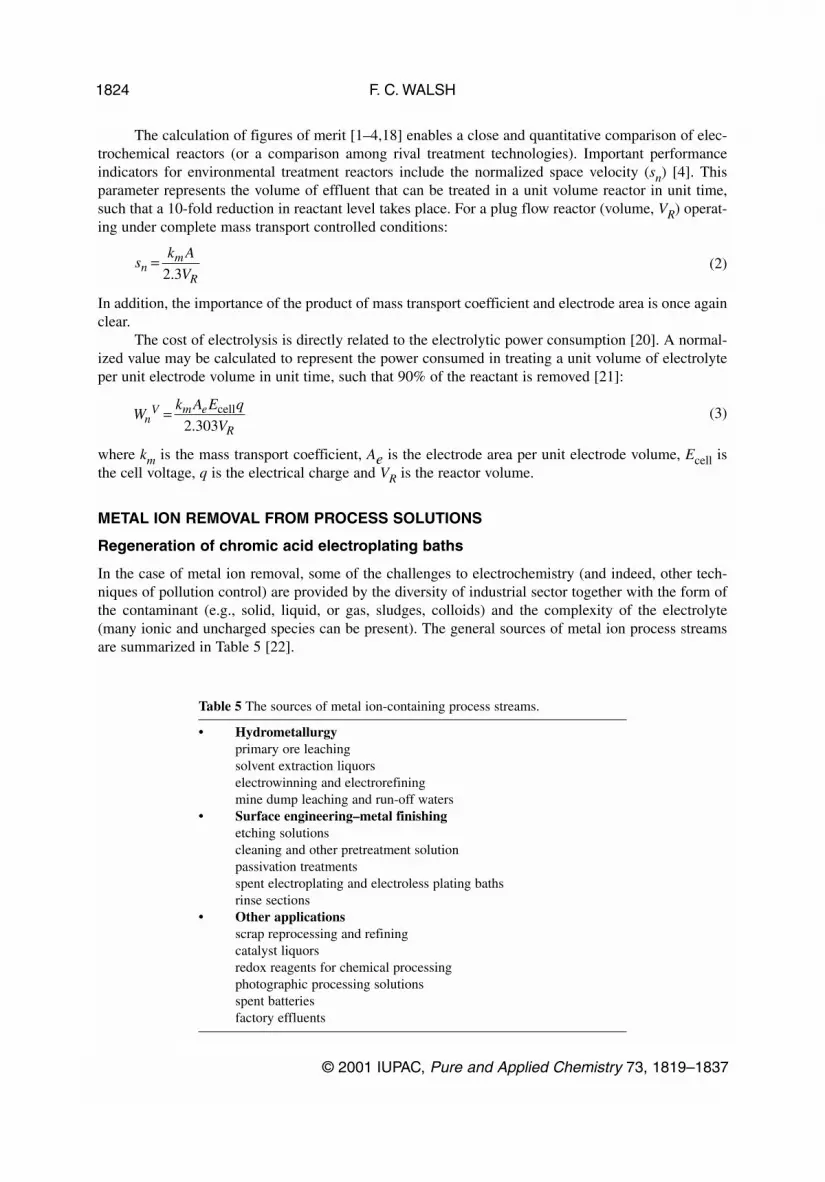
In the case of metal ion removal, some of the challenges to electrochemistry (and indeed, other tech-niques of pollution control) are provided by the diversity of industrial sector together with the form ofthe contaminant (e.g., solid, liquid, or gas, sludges, colloids) and the complexity of the electrolyte(many ionic and uncharged species can be present). The general sources of metal ion process streamsare summarized in Table 5 [22].
F. C. WALSH
© 2001 IUPAC, Pure and Applied Chemistry 73, 1819–1837
1824
sk A
Vnm
R=
2 3.
Wk A E q
VnV m e
R= cell
2 303.
Table 5 The sources of metal ion-containing process streams.
• Hydrometallurgyprimary ore leachingsolvent extraction liquorselectrowinning and electrorefiningmine dump leaching and run-off waters
• Surface engineering–metal finishingetching solutionscleaning and other pretreatment solutionpassivation treatmentsspent electroplating and electroless plating bathsrinse sections
• Other applicationsscrap reprocessing and refiningcatalyst liquorsredox reagents for chemical processingphotographic processing solutionsspent batteriesfactory effluents
Electrochemical techniques offer several approaches to the removal of metal ions from solution.Controlled migration of ions through ion-exchange membranes can be used to remove some cations,while it is also possible to precipitate the metal as the hydroxide due to an increasing near cathode pH.In other processes, anodically generated iron(III) or aluminium(III) ions can be used to precipitate orflocculate metal hydroxides [1,9]. In other cases, it is possible to regenerate a process solution by reduc-tion or oxidation of the active species.
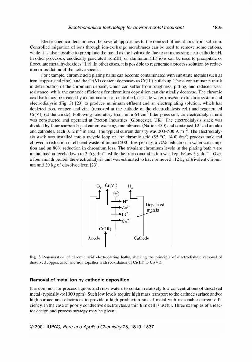
For example, chromic acid plating baths can become contaminated with substrate metals (such asiron, copper, and zinc), and the Cr(VI) content decreases as Cr(III) builds up. These contaminants resultin deterioration of the chromium deposit, which can suffer from roughness, pitting, and reduced wearresistance, while the cathode efficiency for chromium deposition can drastically decrease. The chromicacid bath may be treated by a combination of controlled, cascade water rinse/air extraction system andelectrodialysis (Fig. 3) [23] to produce minimum effluent and an electroplating solution, which hasdepleted iron, copper. and zinc (removed at the cathode of the electrodialysis cell) and regeneratedCr(VI) (at the anode). Following laboratory trials on a 64 cm2 filter-press cell, an electrodialysis unitwas constructed and operated at Poeton Industries (Gloucester, UK). The electrodialysis stack wasdivided by fluorocarbon-based cation-exchange membranes (Nafion 450) and contained 12 lead anodesand cathodes, each 0.12 m2 in area. The typical current density was 200–500 A m–2. The electrodialy-sis stack was installed into a recycle loop on the chromic acid (55 °C, 1400 dm3) process tank andallowed a reduction in effluent waste of around 500 litres per day, a 70% reduction in water consump-tion and an 80% reduction in chromium loss. The trivalent chromium levels in the plating bath weremaintained at levels down to 2–6 g dm–3 while the iron contamination was kept below 3 g dm–3. Overa four-month period, the electrodialysis unit was estimated to have removed 112 kg of trivalent chromi-um and 20 kg of dissolved iron [23].
Removal of metal ion by cathodic deposition
It is common for process liquors and rinse waters to contain relatively low concentrations of dissolvedmetal (typically <<1000 ppm). Such low levels require high mass transport to the cathode surface and/orhigh surface area electrodes to provide a high production rate of metal with reasonable current effi-ciency. In the case of poorly conductive electrolytes, a thin film cell is useful. Three examples of a reac-tor design and process strategy may be given:
© 2001 IUPAC, Pure and Applied Chemistry 73, 1819–1837
Electrochemical technology for environmental treatment 1825
Fig. 3 Regeneration of chromic acid electroplating baths, showing the principle of electrodialytic removal ofdissolved copper, zinc, and iron together with reoxidation of Cr(III) to Cr(VI).
a) Metal can be deposited on a high surface area per unit volume cathode having a porous, 3-dimen-sional structure. Following deposition onto porous carbon materials (typically felt, mesh, fiber, orfoam) the metal may be recovered by furnace refining or by dissolution into a small volume of acorrosive electrolyte. An example is the deposition of copper onto reticulated vitreous carbon ina divided flow-by cell having a rectangular cross-section [24].
b) Metal can be deposited as flake or powder onto the surface of an inner rotating cathode cylinder(usually stainless steel). This allows metal to be scraped off the cathode drum and continuouslyfluidized out of the reactor followed by conventional methods of solid/liquid separation (e.g.,hydrocycloning, filtration, and gravity settlement) [25]. In the majority of RCE reactors, the metalis removed discontinuously from the cathode by peeling and stretching of the cathode surface asin the case of silver extraction from fixer solutions [26] where many hundreds of units are in usethroughout the photographic and metal refining industries.
c) Metal may be deposited onto the cathode surfaces of a thin electrolyte film reactor, such as a bipo-lar trickle tower reactor [22,27]. Such reactors are readily constructed from alternating layers ofporous carbon (typically 3–12 mm thick and thin insulating meshes, ca. 1 mm thick). The anodesites of this undivided cell allow other solution species, e.g., EDTA or cyanide complexants to beoxidized. As in the case of the porous, 3-dimensional cathode reactor, metal may be removedfrom the tower by dissolution into a concentrate or by removal of the packing followed by fur-nace refining.
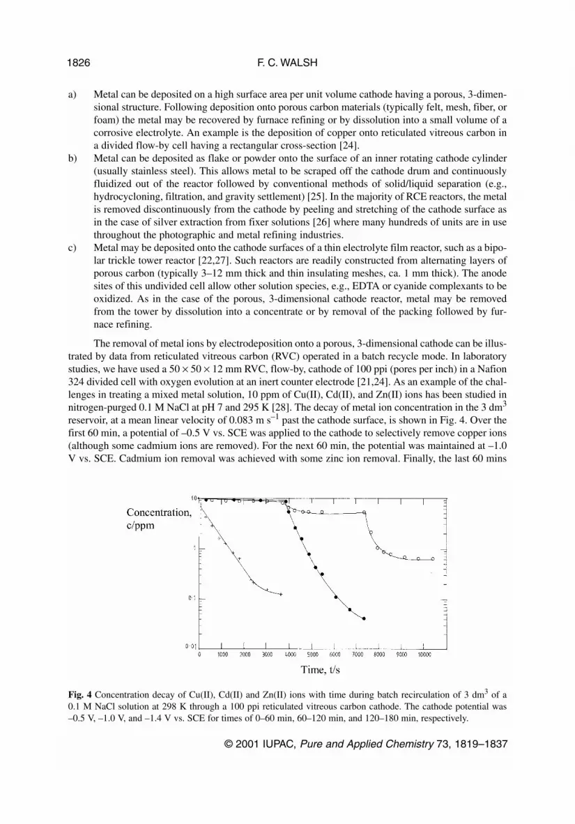
The removal of metal ions by electrodeposition onto a porous, 3-dimensional cathode can be illus-trated by data from reticulated vitreous carbon (RVC) operated in a batch recycle mode. In laboratorystudies, we have used a 50 × 50 × 12 mm RVC, flow-by, cathode of 100 ppi (pores per inch) in a Nafion324 divided cell with oxygen evolution at an inert counter electrode [21,24]. As an example of the chal-lenges in treating a mixed metal solution, 10 ppm of Cu(II), Cd(II), and Zn(II) ions has been studied innitrogen-purged 0.1 M NaCl at pH 7 and 295 K [28]. The decay of metal ion concentration in the 3 dm3
reservoir, at a mean linear velocity of 0.083 m s–1 past the cathode surface, is shown in Fig. 4. Over thefirst 60 min, a potential of –0.5 V vs. SCE was applied to the cathode to selectively remove copper ions(although some cadmium ions are removed). For the next 60 min, the potential was maintained at –1.0V vs. SCE. Cadmium ion removal was achieved with some zinc ion removal. Finally, the last 60 mins
F. C. WALSH
© 2001 IUPAC, Pure and Applied Chemistry 73, 1819–1837
1826
Fig. 4 Concentration decay of Cu(II), Cd(II) and Zn(II) ions with time during batch recirculation of 3 dm3 of a 0.1 M NaCl solution at 298 K through a 100 ppi reticulated vitreous carbon cathode. The cathode potential was–0.5 V, –1.0 V, and –1.4 V vs. SCE for times of 0–60 min, 60–120 min, and 120–180 min, respectively.
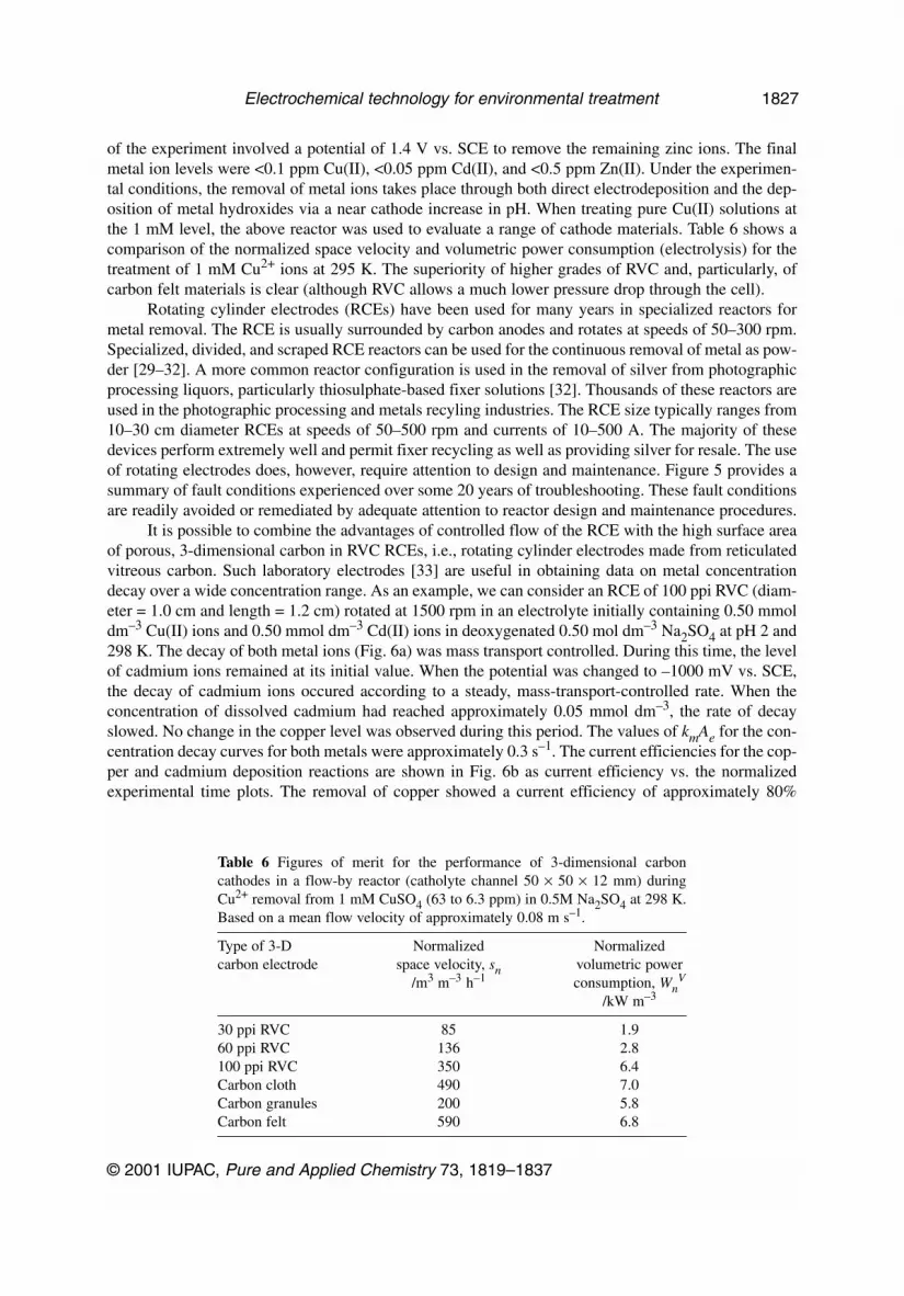
of the experiment involved a potential of 1.4 V vs. SCE to remove the remaining zinc ions. The finalmetal ion levels were <0.1 ppm Cu(II), <0.05 ppm Cd(II), and <0.5 ppm Zn(II). Under the experimen-tal conditions, the removal of metal ions takes place through both direct electrodeposition and the dep-osition of metal hydroxides via a near cathode increase in pH. When treating pure Cu(II) solutions atthe 1 mM level, the above reactor was used to evaluate a range of cathode materials. Table 6 shows acomparison of the normalized space velocity and volumetric power consumption (electrolysis) for thetreatment of 1 mM Cu2+ ions at 295 K. The superiority of higher grades of RVC and, particularly, ofcarbon felt materials is clear (although RVC allows a much lower pressure drop through the cell).
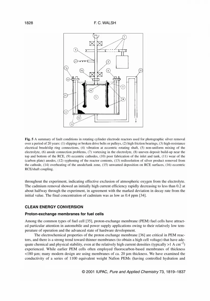
Rotating cylinder electrodes (RCEs) have been used for many years in specialized reactors formetal removal. The RCE is usually surrounded by carbon anodes and rotates at speeds of 50–300 rpm.Specialized, divided, and scraped RCE reactors can be used for the continuous removal of metal as pow-der [29–32]. A more common reactor configuration is used in the removal of silver from photographicprocessing liquors, particularly thiosulphate-based fixer solutions [32]. Thousands of these reactors areused in the photographic processing and metals recyling industries. The RCE size typically ranges from10–30 cm diameter RCEs at speeds of 50–500 rpm and currents of 10–500 A. The majority of thesedevices perform extremely well and permit fixer recycling as well as providing silver for resale. The useof rotating electrodes does, however, require attention to design and maintenance. Figure 5 provides asummary of fault conditions experienced over some 20 years of troubleshooting. These fault conditionsare readily avoided or remediated by adequate attention to reactor design and maintenance procedures.
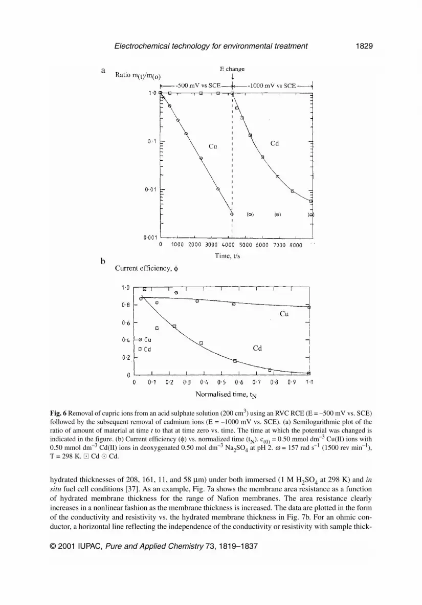
It is possible to combine the advantages of controlled flow of the RCE with the high surface areaof porous, 3-dimensional carbon in RVC RCEs, i.e., rotating cylinder electrodes made from reticulatedvitreous carbon. Such laboratory electrodes [33] are useful in obtaining data on metal concentrationdecay over a wide concentration range. As an example, we can consider an RCE of 100 ppi RVC (diam-eter = 1.0 cm and length = 1.2 cm) rotated at 1500 rpm in an electrolyte initially containing 0.50 mmoldm–3 Cu(II) ions and 0.50 mmol dm–3 Cd(II) ions in deoxygenated 0.50 mol dm–3 Na2SO4 at pH 2 and298 K. The decay of both metal ions (Fig. 6a) was mass transport controlled. During this time, the levelof cadmium ions remained at its initial value. When the potential was changed to –1000 mV vs. SCE,the decay of cadmium ions occured according to a steady, mass-transport-controlled rate. When theconcentration of dissolved cadmium had reached approximately 0.05 mmol dm–3, the rate of decayslowed. No change in the copper level was observed during this period. The values of kmAe for the con-centration decay curves for both metals were approximately 0.3 s–1. The current efficiencies for the cop-per and cadmium deposition reactions are shown in Fig. 6b as current efficiency vs. the normalizedexperimental time plots. The removal of copper showed a current efficiency of approximately 80%
© 2001 IUPAC, Pure and Applied Chemistry 73, 1819–1837
Electrochemical technology for environmental treatment 1827
Table 6 Figures of merit for the performance of 3-dimensional carboncathodes in a flow-by reactor (catholyte channel 50 × 50 × 12 mm) duringCu2+ removal from 1 mM CuSO4 (63 to 6.3 ppm) in 0.5M Na2SO4 at 298 K.Based on a mean flow velocity of approximately 0.08 m s–1.
Type of 3-D Normalized Normalizedcarbon electrode space velocity, sn volumetric power
/m3 m–3 h–1 consumption, WnV
/kW m–3
30 ppi RVC 85 1.960 ppi RVC 136 2.8100 ppi RVC 350 6.4Carbon cloth 490 7.0Carbon granules 200 5.8Carbon felt 590 6.8
throughout the experiment, indicating effective exclusion of atmospheric oxygen from the electrolyte.The cadmium removal showed an initially high current efficiency rapidly decreasing to less than 0.2 atabout halfway through the experiment, in agreement with the marked deviation in decay rate from theinitial value. The final concentration of cadmium was as low as 0.4 ppm [34].
CLEAN ENERGY CONVERSION
Proton-exchange membranes for fuel cells
Among the common types of fuel cell [35], proton-exchange membrane (PEM) fuel cells have attract-ed particular attention in automobile and power supply applications owing to their relatively low tem-perature of operation and the advanced state of hardware development.
The electrochemical properties of the proton exchange membrane [36] are critical in PEM reac-tors, and there is a strong trend toward thinner membranes (to obtain a high cell voltage) that have ade-quate chemical and physical stability, even at the relatively high current densities (typically >1 A cm–2)experienced. While earlier PEM cells often employed fluorocarbon-based membranes of thickness<180 µm; many modern design are using membranes of ca. 20 µm thickness. We have examined theconductivity of a series of 1100 equivalent weight Nafion PEMs (having controlled hydration and
F. C. WALSH
© 2001 IUPAC, Pure and Applied Chemistry 73, 1819–1837
1828
Fig. 5 A summary of fault conditions in rotating cylinder electrode reactors used for photographic silver removalover a period of 20 years: (1) slipping or broken drive belts or pulleys, (2) high friction bearings, (3) high-resistanceelectrical brush/slip ring connections, (4) vibration at eccentric rotating shaft, (5) non-uniform mixing of theelectrolyte, (6) anode connection problems, (7) vortexing in the electrolyte, (8) uneven deposit build-up near thetop and bottom of the RCE, (9) eccentric cathodes, (10) poor fabrication of the inlet and tank, (11) wear of the(carbon plate) anodes, (12) syphoning of the reactor contents, (13) redissolution of silver product removed fromthe cathode, (14) overheating of the anode/tank zone, (15) unwanted deposition on RCE surfaces, (16) eccentricRCE/shaft coupling.
hydrated thicknesses of 208, 161, 11, and 58 µm) under both immersed (1 M H2SO4 at 298 K) and insitu fuel cell conditions [37]. As an example, Fig. 7a shows the membrane area resistance as a functionof hydrated membrane thickness for the range of Nafion membranes. The area resistance clearlyincreases in a nonlinear fashion as the membrane thickness is increased. The data are plotted in the formof the conductivity and resistivity vs. the hydrated membrane thickness in Fig. 7b. For an ohmic con-ductor, a horizontal line reflecting the independence of the conductivity or resistivity with sample thick-
© 2001 IUPAC, Pure and Applied Chemistry 73, 1819–1837
Electrochemical technology for environmental treatment 1829
Fig. 6 Removal of cupric ions from an acid sulphate solution (200 cm3) using an RVC RCE (E = –500 mV vs. SCE)followed by the subsequent removal of cadmium ions (E = –1000 mV vs. SCE). (a) Semilogarithmic plot of theratio of amount of material at time t to that at time zero vs. time. The time at which the potential was changed isindicated in the figure. (b) Current efficiency (φ) vs. normalized time (tN). c(0) = 0.50 mmol dm–3 Cu(II) ions with0.50 mmol dm–3 Cd(II) ions in deoxygenated 0.50 mol dm–3 Na2SO4 at pH 2. ω = 157 rad s–1 (1500 rev min–1),T = 298 K. � Cd � Cd.
a
b
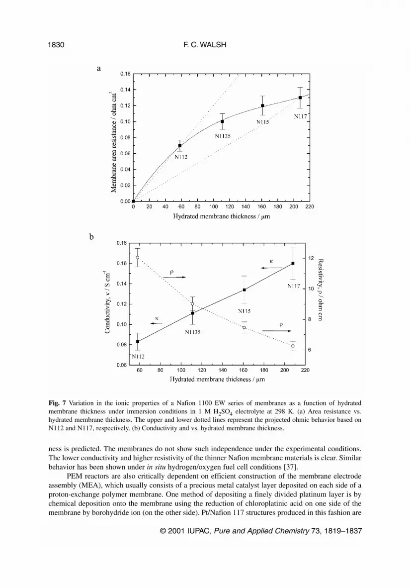
ness is predicted. The membranes do not show such independence under the experimental conditions.The lower conductivity and higher resistivity of the thinner Nafion membrane materials is clear. Similarbehavior has been shown under in situ hydrogen/oxygen fuel cell conditions [37].
PEM reactors are also critically dependent on efficient construction of the membrane electrodeassembly (MEA), which usually consists of a precious metal catalyst layer deposited on each side of aproton-exchange polymer membrane. One method of depositing a finely divided platinum layer is bychemical deposition onto the membrane using the reduction of chloroplatinic acid on one side of themembrane by borohydride ion (on the other side). Pt/Nafion 117 structures produced in this fashion are
F. C. WALSH
© 2001 IUPAC, Pure and Applied Chemistry 73, 1819–1837
1830
Fig. 7 Variation in the ionic properties of a Nafion 1100 EW series of membranes as a function of hydratedmembrane thickness under immersion conditions in 1 M H2SO4 electrolyte at 298 K. (a) Area resistance vs.hydrated membrane thickness. The upper and lower dotted lines represent the projected ohmic behavior based onN112 and N117, respectively. (b) Conductivity and vs. hydrated membrane thickness.
a
b
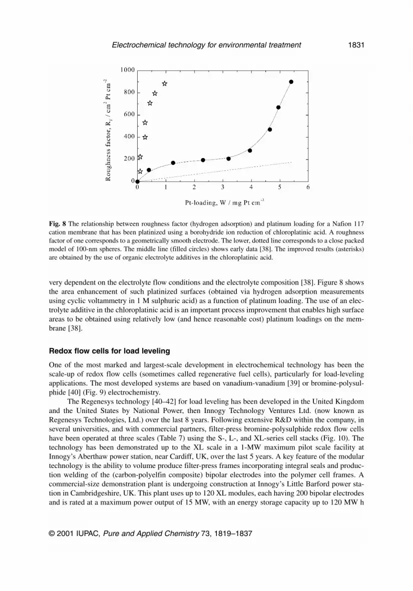
very dependent on the electrolyte flow conditions and the electrolyte composition [38]. Figure 8 showsthe area enhancement of such platinized surfaces (obtained via hydrogen adsorption measurementsusing cyclic voltammetry in 1 M sulphuric acid) as a function of platinum loading. The use of an elec-trolyte additive in the chloroplatinic acid is an important process improvement that enables high surfaceareas to be obtained using relatively low (and hence reasonable cost) platinum loadings on the mem-brane [38].
Redox flow cells for load leveling
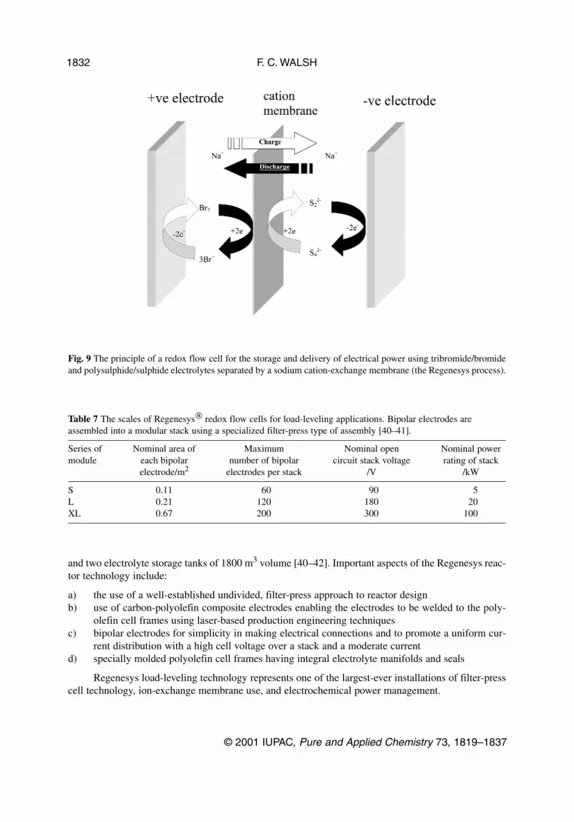
One of the most marked and largest-scale development in electrochemical technology has been thescale-up of redox flow cells (sometimes called regenerative fuel cells), particularly for load-levelingapplications. The most developed systems are based on vanadium-vanadium [39] or bromine-polysul-phide [40] (Fig. 9) electrochemistry.
The Regenesys technology [40–42] for load leveling has been developed in the United Kingdomand the United States by National Power, then Innogy Technology Ventures Ltd. (now known asRegenesys Technologies, Ltd.) over the last 8 years. Following extensive R&D within the company, inseveral universities, and with commercial partners, filter-press bromine-polysulphide redox flow cellshave been operated at three scales (Table 7) using the S-, L-, and XL-series cell stacks (Fig. 10). Thetechnology has been demonstrated up to the XL scale in a 1-MW maximum pilot scale facility atInnogy’s Aberthaw power station, near Cardiff, UK, over the last 5 years. A key feature of the modulartechnology is the ability to volume produce filter-press frames incorporating integral seals and produc-tion welding of the (carbon-polyelfin composite) bipolar electrodes into the polymer cell frames. Acommercial-size demonstration plant is undergoing construction at Innogy’s Little Barford power sta-tion in Cambridgeshire, UK. This plant uses up to 120 XL modules, each having 200 bipolar electrodesand is rated at a maximum power output of 15 MW, with an energy storage capacity up to 120 MW h
© 2001 IUPAC, Pure and Applied Chemistry 73, 1819–1837
Electrochemical technology for environmental treatment 1831
Fig. 8 The relationship between roughness factor (hydrogen adsorption) and platinum loading for a Nafion 117cation membrane that has been platinized using a borohydride ion reduction of chloroplatinic acid. A roughnessfactor of one corresponds to a geometrically smooth electrode. The lower, dotted line corresponds to a close packedmodel of 100-nm spheres. The middle line (filled circles) shows early data [38]. The improved results (asterisks)are obtained by the use of organic electrolyte additives in the chloroplatinic acid.
and two electrolyte storage tanks of 1800 m3 volume [40–42]. Important aspects of the Regenesys reac-tor technology include:
a) the use of a well-established undivided, filter-press approach to reactor designb) use of carbon-polyolefin composite electrodes enabling the electrodes to be welded to the poly-
olefin cell frames using laser-based production engineering techniquesc) bipolar electrodes for simplicity in making electrical connections and to promote a uniform cur-
rent distribution with a high cell voltage over a stack and a moderate currentd) specially molded polyolefin cell frames having integral electrolyte manifolds and seals
Regenesys load-leveling technology represents one of the largest-ever installations of filter-presscell technology, ion-exchange membrane use, and electrochemical power management.
F. C. WALSH
© 2001 IUPAC, Pure and Applied Chemistry 73, 1819–1837
1832
Fig. 9 The principle of a redox flow cell for the storage and delivery of electrical power using tribromide/bromideand polysulphide/sulphide electrolytes separated by a sodium cation-exchange membrane (the Regenesys process).
Table 7 The scales of Regenesys redox flow cells for load-leveling applications. Bipolar electrodes areassembled into a modular stack using a specialized filter-press type of assembly [40–41].
Series of Nominal area of Maximum Nominal open Nominal powermodule each bipolar number of bipolar circuit stack voltage rating of stack
electrode/m2 electrodes per stack /V /kW
S 0.11 60 90 5L 0.21 120 180 20XL 0.67 200 300 100
SUMMARY
Environmental electrochemical technology
Electrochemical technology is an essential and enabling discipline in many sectors of environmentaltreatment, including clean synthesis, monitoring of process efficiency and pollutants, removal of con-taminants, recycling of process streams, water sterilization, clean energy conversion, and the efficientstorage and utilization of electrical energy.
© 2001 IUPAC, Pure and Applied Chemistry 73, 1819–1837
Electrochemical technology for environmental treatment 1833
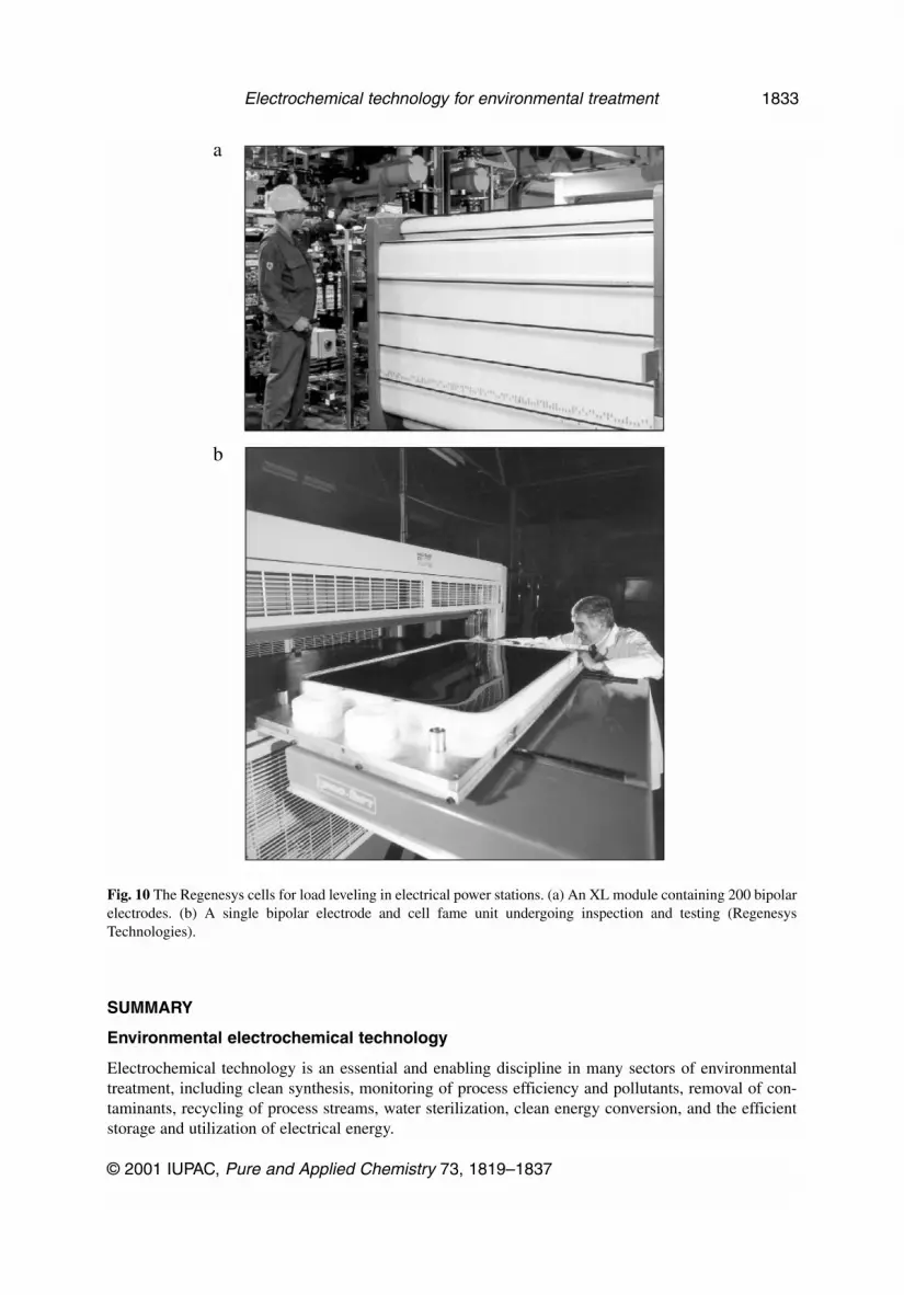
Fig. 10 The Regenesys cells for load leveling in electrical power stations. (a) An XL module containing 200 bipolarelectrodes. (b) A single bipolar electrode and cell fame unit undergoing inspection and testing (RegenesysTechnologies).
a
b
The field of environmental electrochemistry has witnessed many developments and has demon-strated many successes, as evidenced by the growing literature. The present paper has provided the fol-lowing examples of environmental electrochemistry on the laboratory, pilot and full industrial scale intwo application areas:
a) Metal ion removal can be carried out from aqueous, low-concentration solutions using the tech-nologies of electrodialysis and anodic regeneration of reagents and electrodeposition at 3-dimen-sional cathodes such as RVC, RCEs, and combined RVC RCEs.
b) Clean energy conversion can be achieved using PEMs and membrane electrode assemblies asessential components in PEM fuel cells and related technologies together with the developmentof large-scale, load-leveling fuel cells based on modular, redox flow cell technology.
Trends in environmental electrochemical technology
Major trends in reactor design have included [1–17]:
• more compact and modular reactor designs• production engineering of cell components to allow economic, high-volume production• development of large-scale bipolar electrode reactors, which offer good current distribution and
require only the end-feeder electrodes to be directly connected to a power supply • increasing availability of porous, 3-dimensional electrodes in carbon or metal• use of gas-diffusion electrodes not only in fuel cells but also in technologies such as chlor-alkali,
pollution control, and organic electrosynthesis• more efficient solid polymer electrode structures for PEM fuel cells and many other applications• small gap cells to minimize ohmic losses• hybrid cells, which combine electrochemical functions with, e.g., gas absorption or ion exchange
Challenges to the development of environmental electrochemistry
It has been traditional to teach electrochemistry in universities as part of physical chemistry and to stressthe more reversible, thermodynamic aspects of the subject. Fortunately, this old fashioned approach ischanging, and practitioners in chemistry, materials, and chemical engineering departments are now pro-viding lectures and laboratory classes in modern electrochemistry. The author has advocated an inte-grated approach to electrochemistry, where the fundamental science and techniques are taught viaknowledge of the industrial applications [43]. A case history format is particularly useful in bridgingthe gap between laboratory science and industrial technology.
The last 10 years have seen the publication of a large number of electrochemistry texts. Whilemost of these consider fundamental electrode kinetics, electroanalysis, and laboratory techniques, therehave been some key texts on industrial electrochemistry and electrochemical engineering.
The development of modular courses on aspects of electrochemical engineering is important tothe success of industrial processes. It is pleasing to see that a number of short courses are becomingavailable for postgraduates and industrial delegates. The availability of modular postgraduate courses,suitable for industry or academia is critical to future developments, particularly in the fields of envi-ronmental technology, membrane applications, and fuel cell design. Such courses will complementexisting provision in, e.g., corrosion, surface finishing, and laboratory techniques in electrochemistry.For example, undergraduate teaching material is available in the areas of fluid dispersion [44], fractionalconversion in electrochemical reactors under mass transport control [45], a practical demonstration ofsimple batteries [46], and the removal of metal ions from solution [47].
The continued development of environmental electrochemical engineering must be seen as criti-cal to the future success of technologies as diverse as solar cells, automotive fuel cells, load-levelingredox batteries, chemicals and biosensors, pollution-control processes, and the synthesis of materials
F. C. WALSH
© 2001 IUPAC, Pure and Applied Chemistry 73, 1819–1837
1834
and coatings technology for the electronics industry. It is important that postgraduate schools expandteaching, research, and short course training in this important discipline.
In the area of reactor design, continuing challenges to the field of environmental electrochemicalengineering include:
• improved electrode structures (having high surface area, improved electrocatalytic ability, andcapable of low-cost, volume production);
• improved ion-exchange membranes (having better selectivity, controlled solvent transport, andlower-cost, yet high stability);
• published comparisons between electrochemical routes and chemical/physical ones, for a partic-ular application (e.g., energy transformation, chemical monitoring, synthesis, or pollution con-trol);
• quantitative treatments of the performance of various electrochemical reactors for a particularapplication (such as metal ion removal or removal of organics);
• accessible case histories of successful electrochemical technologies, which include descriptionsof scale-up, process experience, and competitive technologies;
• integration of electrochemical devices and reactors with other devices and unit processes (e.g.,optical-electrochemical sensors, electrochemically assisted ion exchange, and combined adsorp-tion/electrochemical treatment of soluble contaminants); and
• an integrated Web site, which provides easy access to the many subfields of electrochemistry(such as corrosion, surface finishing, power sources, electrosynthesis, pollution control, sensors,and electrochemical materials).
An essential need is the development of recognized centers of excellence, where interdisciplinaryteams can develop both the science and technology of electrochemistry in close collaboration withindustry and government research organizations. Such centers would provide a seamless and two-waytransition from a laboratory R&D environment to pilot-scale electrochemical reactor facilities.
ACKNOWLEDGMENTS
Contributions by research workers Gavin Reade, Sally Ann Sheppard, Sharon Slade, and Ian Whyte,and my colleagues Dr. Sheelagh Campbell and Prof. Derek Pletcher at the Universities of Portsmouthand Southampton, UK, are grateful acknowledged. This work has been supported by DERA, E ATechnology, The ETSU Environmental Technology Best Practice Programme, Johnson MattheyTechnology Centre, Innogy Technology Ventures Limited (now Regenesys Technologies), PoetonIndustries Limited. and the Engineering and Physical Sciences Research Council. This paper was pre-sented as an introductory lecture to the IUPAC Conference and Workshop on Electrochemistry andInterfacial Chemistry in Environmental Clean-up and Green Chemical Processes, 6–7 April 2001,Coimbra, Portugal.
REFERENCES
1. D. Pletcher and F. C. Walsh. Industrial Electrochemistry, 2nd ed., Chapman & Hall, London(1990).
2. F. C. Walsh. A First Course in Electrochemical Engineering, The Electrochemical Consultancy,Romsey (1993); F. C. Walsh, J. Gonzalez-Garcia, V. Montiel Leguey. Un Primer Curso deIngenieria Electroquimica Imprenta Gamma, San Vicente, Alicante (2000).
3. F. Goodridge and K. Scott. Electrochemical Process Engineering, Plenum Press, New York(1995).
4. G. Kreysa (Ed.). Electrochemical Cell Design and Optimisation Procedures, DechemaMonograph, 123 (1992).
© 2001 IUPAC, Pure and Applied Chemistry 73, 1819–1837
Electrochemical technology for environmental treatment 1835
5. D. Pletcher and F. C. Walsh. Chem. Ind. 17 September, 564–566 (2001).6. C. A. C. Sequeira (Ed.). Environmentally Oriented Electrochemistry, Elevier, Amsterdam (1994).7. J. O ’M. Bockris (Ed.). The Electrochemistry of Cleaner Environments, Plenum Press, New York
(1972).8. C. Comninellis. In Environmentally Oriented Electrochemistry, C. A. C. Sequeira (Ed.), pp.
77–101, Elsevier, Amsterdam (1994).9. K. Scott. Electrochemical Processes for Clean Technology, The Royal Society of Chemistry,
London (1995).10. J. D. Genders and N. L. Weinberg. The Electrochemistry of Cleaner Environments, The
Electrosynthesis Co., Lancaster, New York (1992).11. P. M. Bersier. Chem. List 89, 742–755 (1995).12. A. M. Couper, D. Pletcher, F. C. Walsh. Chem. Rev. 90, 837–865 (1990).13. T. A. Davis, J. D. Genders, D. Pletcher. Ion Permeable Membranes, The Electrochemical
Consultancy, Romsey (1997).14. F. C. Walsh and G. W. Reade. Analyst 119, 791–803 (1994).15. F. C. Walsh and G. A. Mills. Chem. Tech. Europe 1 (1), 13–20 (1994).16. K. Scott and F. C. Walsh. Electrochem. Eng., Chem. Ind. 26 July, 493–497 (1993).17. P. M. Bersier, L. Carlsson, J. Bersier. Top. Curr. Chem. 170, 114–229 (1994).18. F. C. Walsh and G. W. Reade. Analyst 119, 791–803 (1994).19. D. Pletcher and F. C. Walsh. In Electrochemical Technology for a Cleaner Environment, J. D.
Genders and N. L. Weinberg (Eds.), pp. 52–100, The Electrosynthesis Co., Lancaster, New York(1992).
20. F. C. Walsh. Bull. Electrochem. 8, 471–474 (1992).21. F. C. Walsh, D. Pletcher, I. Whyte. J. Chem. Technol. Biotechnol. 55, 147–155 (1992).22. F. C. Walsh and G. W. Reade. In Environmentally Oriented Electrochemistry, C. A. C. Sequeira
(Ed.), pp. 3–41, Elsevier, Amsterdam (1994).23. “Reducing Costs in Hard Chrome Plating” ETSU Leaflet FP91, 1999; ETSU, Harwell, Didcot,
Oxon OX11 0RA, UK; a collaborative project with Poeton Industries Ltd., PMD (UK) Ltd.,Elementis Chromium and FHM Division, Claverham Ltd.
24. I. Whyte, D. Pletcher, F. C. Walsh, J. P. Millington. J. Appl. Electrochem. 21, 667–671 (1991).25. F. C. Walsh. In The Electrochemistry of Cleaner Environments, J. D. Genders and N. L. Weinberg
(Eds.), pp. 101–159, The Electrosynthesis Co., Lancaster, New York (1992).26. F. C. Walsh. I. Chem. E. Symp. Ser. 98, 139–149 (1986).27. F. C. Walsh and D. E. Saunders. J. Photog. Sci. 31, 35–42 (1983).28. M. Fleischmann, C. J. H. King, J. W. Oldfield, R. E. Plimley, C. L. K. Tennakoon. British Patent
1,419,246, (1971).29. D. R. Gabe, F. C. Walsh, G. D. Wilcox, J. Gonzalez-Garcia. J. Appl. Electrochem. 28, 759–780
(1998).30. F. C. Walsh and N.A. Gardner. In Electrochemical Cell Design, R. E. White (Ed.), pp. 225–258,
Plenum, New York, (1984).31. D. R. Gabe and F. C. Walsh. I. Chem. E. Symp. Ser. 116, 219–229 (1990).32. D. Robinson and F. C. Walsh. J. Photog. Sci. 42, 1–11 (1994).33. A. H. Nahlé, G. W. Reade, F. C. Walsh. J. Appl. Electrochem. 25, 450–455 (1995).34. G. W. Reade, A. H. Nahle, P. Bond, F. C. Walsh. J. Chem. Technol. Biotechnol. To be submitted.35. R. Kingston. Chem. Br. 36 (6), 24–28 (2000).36. O. Savadogo. J. New Mat. Electrochem. Syst. 1, 47 (1998).37. S. Slade, S. A. Campbell, R. R. Ralph, F. C. Walsh. J. Electrochem. Soc. (2002). Accepted for
publication.38. S. A. Sheppard, S. A. Campbell, J. R. Smith, G. W. Lloyd, T. R. Ralph, F. C. Walsh. Analyst 123,
1923–1929 (1998).
F. C. WALSH
© 2001 IUPAC, Pure and Applied Chemistry 73, 1819–1837
1836
39. E. Sum and M. Skyllas-Kazacos. J. Power Sources 15, 179–190 (1985).40. A. Price, S. Bartley, S. Male, G. Cooley. Power Eng. J. 13 (3), 122–129 (1999).41. Regenesys Technologies Ltd., Harwell International Business Centre, Harwell, Didcot, Oxon,
OX11 0QA, UK; [email protected]. F. C. Walsh. The Chemical Engineer, 29–31 October (2001).43. G. A. Ottewill and F. C. Walsh. Electrochem. Newsletter January, 19–25 (1996).44. J. A. Conesa, J. Gonzalez-Garcia, J. Iniesta, P. Bonete, M. Ingles, E. Exposito, V. Garcia-Garcia,
V. Montiel. Chem. Eng. Educ. Fall, 300–304 (1999).45. P. Trinidad, F. C. Walsh, D. Gilroy. Int. J. Eng. Educ. 14, 431–441 (1998).46. X. LeRoux. J. Chem. Educ. 73, 811–817 (1996).47. G. A. Ottewill, G. W. Reade, S. A. Campbell, F. C. Walsh. Green Chem. (2002). In press.
© 2001 IUPAC, Pure and Applied Chemistry 73, 1819–1837
Electrochemical technology for environmental treatment 1837