Embed Size (px)
Citation preview
ENR202 Mechanics of Materials Lecture 12B Slides and Notes
Slide 1
Do not remove this notice.
COMMMONWEALTH OF AUSTRALIACopyright Regulations 1969
WARNING
This material has been produced and communicated to you by or on
behalf of the University of South Australia pursuant to Part VB of the
Copyright Act 1968 (the Act).
The material in this communication may be subject to copyright under the
Act. Any further reproduction or communication of this material by you
may be the subject of copyright protection under the Act.
Do not remove this notice.
Copyright Notice
ENR202 Mechanics of Materials Lecture 12B Slides and Notes
Slide 2
Lecture 12b – Stress Transformation
and Principal Stresses (w1)
ENR 202 Mechanics and Structures
Now, you know how to calculate normal stress and shear stress at any plane for given plane state of stress from previous lecture. Now we are interested on which plane we have maximum and minimum normal stress and which plane we have maximum shear stresses acting.
ENR202 Mechanics of Materials Lecture 12B Slides and Notes
Slide 3
Principal In-Plane Stresses
• x’ and x’y’ depend on the angle of inclination of the plane on
which these stresses act
• For design purpose, the largest positive and negative stresses
are usually needed
• To determine the maximum and minimum normal stresses, which
are known as the principal stresses, we must differentiate the
equation for x’ with respect to and set the result equal to zero
ENR202 12b -- Slide No. 3
normal stress sigma x dash and shear stress tou x dash y dash depend on the angle of inclination theta of the plane on which we interested on these stresses. In engineering, you need to find largest positive stress and largest negative stress for design purpose. You studied in mathematics that if you want to determine maximum and minimum of any equation, we must differentiate the equation and the result equal to zero. We use same concept here, we are interested to find maximum and minimum normal stresses are known as principal stresses, we differentiate the equation 4 in slide 11 of previous lecture 12a with respect to theta and set the result equal to zero.
ENR202 Mechanics of Materials Lecture 12B Slides and Notes
Slide 4
• Lots more tricky maths reveals that the maximum In-Plane or
Principal Stress acting on an element can be found by adding the
maximum In-Plane Shear stress to the average Normal stress
• Likewise this minimum In-Plane or Principal Stress acting on an
element can be found by subtracting the maximum In-Plane Shear
stress from the average Normal stress
Principal In-Plane Stresses
ENR202 12b -- Slide No. 4
Differentiation of equation 4 of previous lecture 12a in slide 11 with respect to theta need so much mathematical back ground. If you are interested on this please have a look a book on Mechanics of Materials, seventh SI edition by author R.C. Hibbeler in the chapter 9 of pages 476 477 and 478 to get more information on differentiation of equation 4.
ENR202 Mechanics of Materials Lecture 12B Slides and Notes
Slide 5
Principal In-Plane Stresses
2
2
2xy
yx
2
yx
2
2
2,122
xy
yxyx
Average Normal Stress =
Maximum Shear Stress =
Principal Stresses =
The angle of inclination of the principal stress plane =
)(
22tan
yx
xy
P
ENR202 12b -- Slide No. 5
(7)
(8)
(9)
(10)
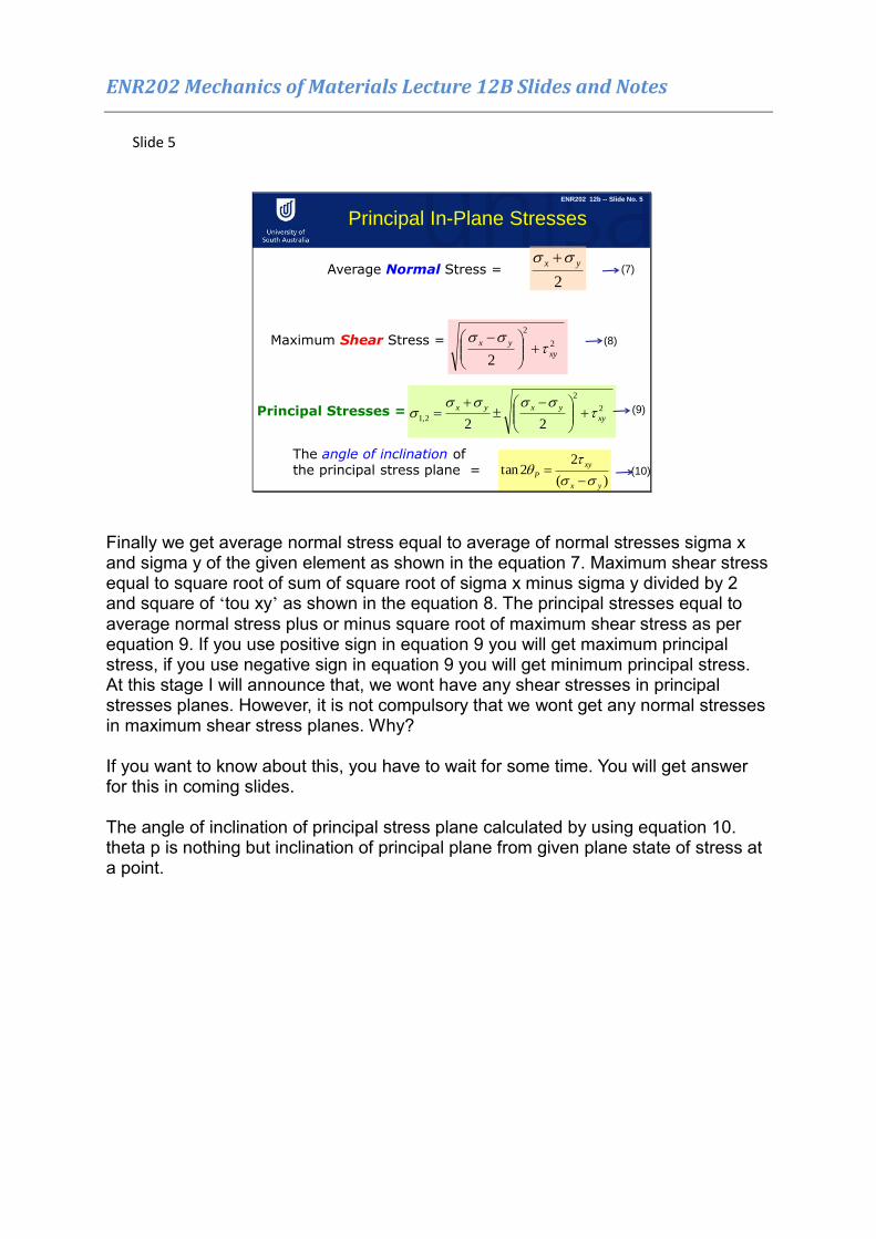
Finally we get average normal stress equal to average of normal stresses sigma x and sigma y of the given element as shown in the equation 7. Maximum shear stress equal to square root of sum of square root of sigma x minus sigma y divided by 2 and square of ‘tou xy’ as shown in the equation 8. The principal stresses equal to average normal stress plus or minus square root of maximum shear stress as per equation 9. If you use positive sign in equation 9 you will get maximum principal stress, if you use negative sign in equation 9 you will get minimum principal stress. At this stage I will announce that, we wont have any shear stresses in principal stresses planes. However, it is not compulsory that we wont get any normal stresses in maximum shear stress planes. Why? If you want to know about this, you have to wait for some time. You will get answer for this in coming slides. The angle of inclination of principal stress plane calculated by using equation 10. theta p is nothing but inclination of principal plane from given plane state of stress at a point.
ENR202 Mechanics of Materials Lecture 12B Slides and Notes
Slide 6
Maximum In-Plane Shear Stress
2
2
2xy
yx
Maximum Shear Stress =
And this maximum shear occurs at an angle of 450 to the angle of inclinationof the principal stress plane
ENR202 12b -- Slide No. 6
(11)
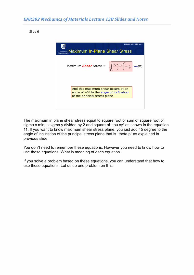
The maximum in plane shear stress equal to square root of sum of square root of sigma x minus sigma y divided by 2 and square of ‘tou xy’ as shown in the equation 11. If you want to know maximum shear stress plane, you just add 45 degree to the angle of inclination of the principal stress plane that is ‘theta p’ as explained in previous slide. You don’t need to remember these equations. However you need to know how to use these equations. What is meaning of each equation. If you solve a problem based on these equations, you can understand that how to use these equations. Let us do one problem on this.
ENR202 Mechanics of Materials Lecture 12B Slides and Notes
Slide 7
Determine the principal stresses at point A and B from the example
in last week’s lecture. Also determine the orientation of the Principal
Stress plane at point B.26kN
Example 2
ENR202 12b -- Slide No. 7
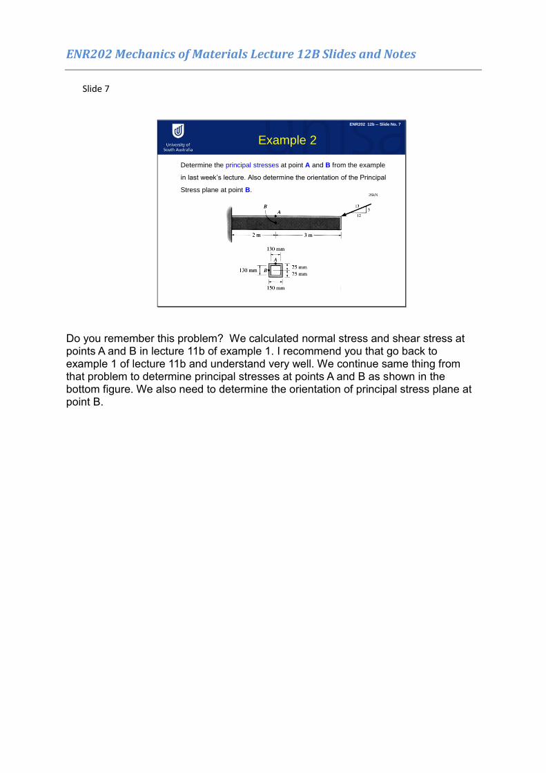
Do you remember this problem? We calculated normal stress and shear stress at points A and B in lecture 11b of example 1. I recommend you that go back to example 1 of lecture 11b and understand very well. We continue same thing from that problem to determine principal stresses at points A and B as shown in the bottom figure. We also need to determine the orientation of principal stress plane at point B.
ENR202 Mechanics of Materials Lecture 12B Slides and Notes
Slide 8
Example 2 Solution
• These were the stresses at A………
2
2
2,122
xy
yxyx
Principal Stresses at Point A
σX = 110.6MPa σY = 0 XY = 0
2
xy
2
2,1 02
06.110
2
06.110
σ1 = 110.6MPa, σ2 = 0
….as expected!!
ENR202 12b -- Slide No. 8
(12)
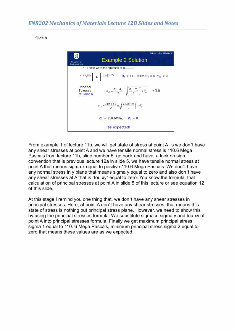
From example 1 of lecture 11b, we will get state of stress at point A is we don’t have any shear stresses at point A and we have tensile normal stress is 110.6 Mega Pascals from lecture 11b, slide number 5. go back and have a look on sign convention that is previous lecture 12a in slide 5. we have tensile normal stress at point A that means sigma x equal to positive 110.6 Mega Pascals. We don’t have any normal stress in y plane that means sigma y equal to zero and also don’t have any shear stresses at A that is ‘tou xy’ equal to zero. You know the formula that calculation of principal stresses at point A in slide 5 of this lecture or see equation 12 of this slide. At this stage I remind you one thing that, we don’t have any shear stresses in principal stresses. Here, at point A don’t have any shear stresses, that means this state of stress is nothing but principal stress plane. However, we need to show this by using the principal stresses formula. We substitute sigma x, sigma y and tou xy of point A into principal stresses formula. Finally we get maximum principal stress sigma 1 equal to 110. 6 Mega Pascals, minimum principal stress sigma 2 equal to zero that means these values are as we expected.
ENR202 Mechanics of Materials Lecture 12B Slides and Notes
Slide 9
Example 2 Solution
• These were the stresses at B………
2
2
2,122
xy
yxyx
σX = -4.3MPa σY = 0 XY = -4MPa
σ1 = 2.3MPa, σ2 = -6.7MPa
Principal Stresses at Point B
)4(2
03.4
2
03.4 2
2
2,1
The angle of inclination of the principal stress plane =
)(
22tan
yx
xy
P
86.1
3.4
8
)03.4(
4*22tan P
= 30.90
ENR202 12b -- Slide No. 9
(13)
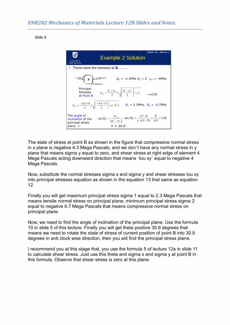
The state of stress at point B as shown in the figure that compressive normal stress in x plane is negative 4.3 Mega Pascals, and we don’t have any normal stress in y plane that means sigma y equal to zero, and shear stress at right edge of element 4 Mega Pascals acting downward direction that means ‘tou xy’ equal to negative 4 Mega Pascals. Now, substitute the normal stresses sigma x and sigma y and shear stresses tou xy into principal stresses equation as shown in the equation 13 that same as equation 12. Finally you will get maximum principal stress sigma 1 equal to 2.3 Mega Pascals that means tensile normal stress on principal plane, minimum principal stress sigma 2 equal to negative 6.7 Mega Pascals that means compressive normal stress on principal plane. Now, we need to find the angle of inclination of the principal plane. Use the formula 10 in slide 5 of this lecture. Finally you will get theta positive 30.9 degrees that means we need to rotate the state of stress of current position of point B into 30.9 degrees in anti clock wise direction, then you will find the principal stress plane. I recommend you at this stage that, you use the formula 5 of lecture 12a in slide 11 to calculate shear stress. Just use this theta and sigma x and sigma y at point B in this formula. Observe that shear stress is zero at this plane.
ENR202 Mechanics of Materials Lecture 12B Slides and Notes
Slide 10
Example 2 Solution
ENR202 12b -- Slide No. 10
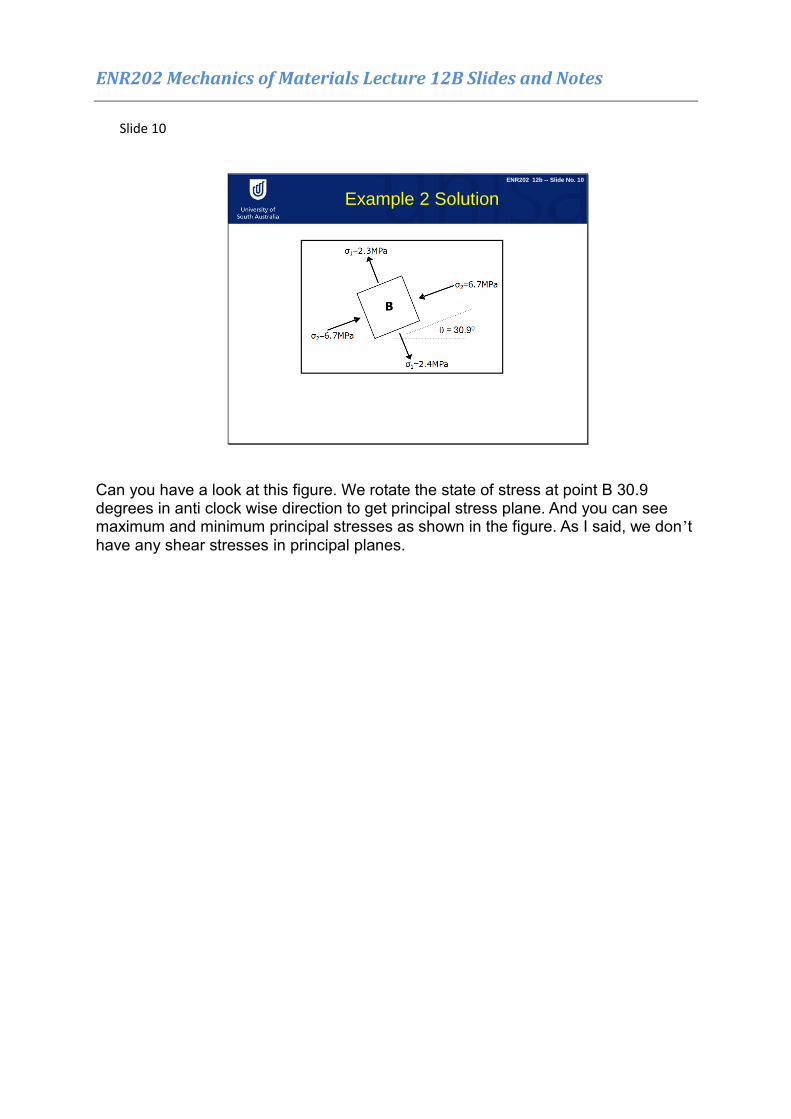
Can you have a look at this figure. We rotate the state of stress at point B 30.9 degrees in anti clock wise direction to get principal stress plane. And you can see maximum and minimum principal stresses as shown in the figure. As I said, we don’t have any shear stresses in principal planes.
ENR202 Mechanics of Materials Lecture 12B Slides and Notes
Slide 11
Example 3
150 mm12 mm
15 mm130 mm
A
150 mm12 mm
15 mm130 mm
B
150 mm12 mm
15 mm130 mm
A
150 mm12 mm
15 mm130 mm
B
From last week - Determine the Principal Stresses acting on the element at point A and specify its orientation.
44.6MPa
A
44.6 MPa
3.2 MPa
3.2 MPa
ENR202 12b -- Slide No. 11
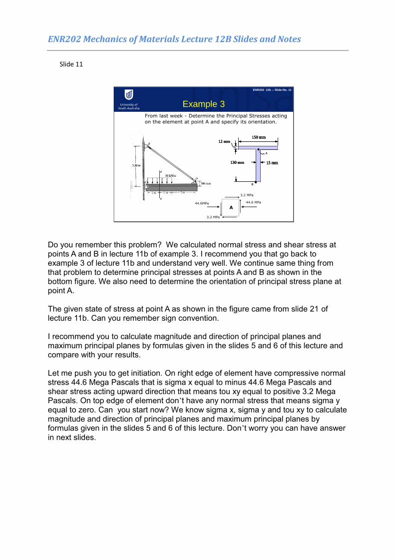
Do you remember this problem? We calculated normal stress and shear stress at points A and B in lecture 11b of example 3. I recommend you that go back to example 3 of lecture 11b and understand very well. We continue same thing from that problem to determine principal stresses at points A and B as shown in the bottom figure. We also need to determine the orientation of principal stress plane at point A. The given state of stress at point A as shown in the figure came from slide 21 of lecture 11b. Can you remember sign convention. I recommend you to calculate magnitude and direction of principal planes and maximum principal planes by formulas given in the slides 5 and 6 of this lecture and compare with your results. Let me push you to get initiation. On right edge of element have compressive normal stress 44.6 Mega Pascals that is sigma x equal to minus 44.6 Mega Pascals and shear stress acting upward direction that means tou xy equal to positive 3.2 Mega Pascals. On top edge of element don’t have any normal stress that means sigma y equal to zero. Can you start now? We know sigma x, sigma y and tou xy to calculate magnitude and direction of principal planes and maximum principal planes by formulas given in the slides 5 and 6 of this lecture. Don’t worry you can have answer in next slides.

ENR202 Mechanics of Materials Lecture 12B Slides and Notes
Slide 12
Example 3-Principle Stesses
= 4.10
A
σ2=44.8MPa
σ2=44.8MPa
σ1=0.23MPaσ1=0.23MPa
ENR202 12b -- Slide No. 12
44.6MPa
A
44.6 MPa
3.2 MPa
3.2 MPa
The state of stress at point A as shown in the figure that compressive normal stress in x plane is negative 44.6 Mega Pascals, and we don’t have any normal stress in y plane that means sigma y equal to zero, and shear stress at right edge of element 3.2 Mega Pascals acting upward direction that means ‘tou xy’ equal to positive 3.2 Mega Pascals. Now, substitute the normal stresses sigma x and sigma y and shear stresses ‘tou xy’ into principal stresses equation. Finally you will get maximum principal stress sigma 1 equal to 0.23 Mega Pascals that means tensile normal stress on principal plane, minimum principal stress sigma 2 equal to positive 44.8 Mega Pascals that means tensile normal stress on principal plane. Now, we need to find the angle of inclination of the principal plane. Use the formula 10 in slide 5 of this lecture. Finally you will get theta negative 4.1 degrees that means we need to rotate the state of stress of current position of point B into 4.1 degrees in clock wise direction. So, we find the principal stress plane. Can you use the formula 5 of lecture 12a in slide 11 to calculate shear stress. Just use this theta and sigma x and sigma y at point B in this formula. Observe that shear stress is zero at this plane or not.
ENR202 Mechanics of Materials Lecture 12B Slides and Notes
Slide 13
Example 3 – Max Shear Stress
= 40.90
A
σAv=22.3MPa
Max=22.53MPa
σAv=22.3MPaMax=22.53MPa
ENR202 12b -- Slide No. 13
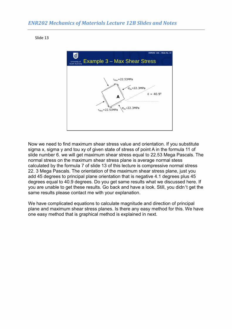
Now we need to find maximum shear stress value and orientation. If you substitute sigma x, sigma y and tou xy of given state of stress of point A in the formula 11 of slide number 6. we will get maximum shear stress equal to 22.53 Mega Pascals. The normal stress on the maximum shear stress plane is average normal stess calculated by the formula 7 of slide 13 of this lecture is compressive normal stress 22. 3 Mega Pascals. The orientation of the maximum shear stress plane, just you add 45 degrees to principal plane orientation that is negative 4.1 degrees plus 45 degrees equal to 40.9 degrees. Do you get same results what we discussed here. If you are unable to get these results. Go back and have a look. Still, you didn’t get the same results please contact me with your explanation. We have complicated equations to calculate magnitude and direction of principal plane and maximum shear stress planes. Is there any easy method for this. We have one easy method that is graphical method is explained in next.
ENR202 Mechanics of Materials Lecture 12B Slides and Notes
Slide 14
Mohr's Circle of Plane Stress
avg
x y
2R
x y
xy
( )
2
2 2
and
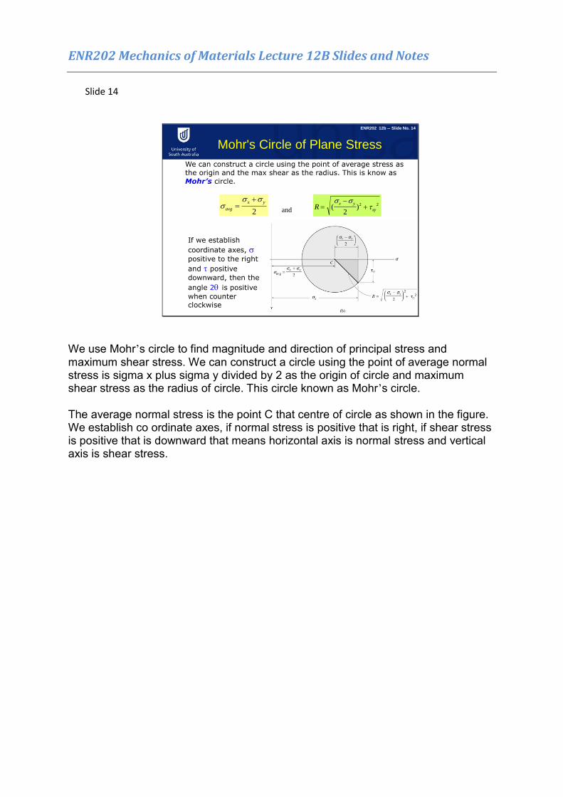
We can construct a circle using the point of average stress as the origin and the max shear as the radius. This is know as Mohr’s circle.
If we establish
coordinate axes, positive to the right
and positive
downward, then the
angle 2 is positive
when counter clockwise
ENR202 12b -- Slide No. 14
We use Mohr’s circle to find magnitude and direction of principal stress and maximum shear stress. We can construct a circle using the point of average normal stress is sigma x plus sigma y divided by 2 as the origin of circle and maximum shear stress as the radius of circle. This circle known as Mohr’s circle. The average normal stress is the point C that centre of circle as shown in the figure. We establish co ordinate axes, if normal stress is positive that is right, if shear stress is positive that is downward that means horizontal axis is normal stress and vertical axis is shear stress.
ENR202 Mechanics of Materials Lecture 12B Slides and Notes
Slide 15
Mohr's Circle - Plane Stress
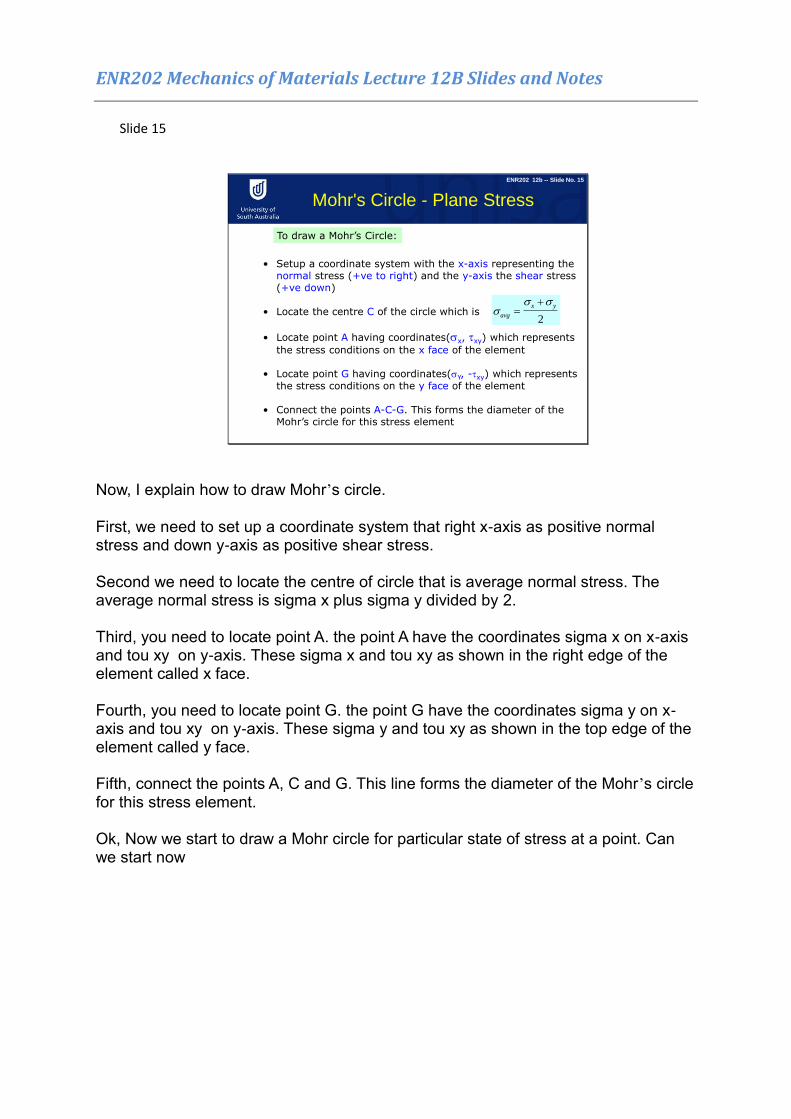
To draw a Mohr’s Circle:
• Setup a coordinate system with the x-axis representing the normal stress (+ve to right) and the y-axis the shear stress (+ve down)
• Locate the centre C of the circle which is
• Locate point A having coordinates(x, xy) which represents
the stress conditions on the x face of the element
• Locate point G having coordinates(Y, -xy) which represents
the stress conditions on the y face of the element
• Connect the points A-C-G. This forms the diameter of the Mohr’s circle for this stress element
avg
x y
2
ENR202 12b -- Slide No. 15
Now, I explain how to draw Mohr’s circle. First, we need to set up a coordinate system that right x-axis as positive normal stress and down y-axis as positive shear stress. Second we need to locate the centre of circle that is average normal stress. The average normal stress is sigma x plus sigma y divided by 2. Third, you need to locate point A. the point A have the coordinates sigma x on x-axis and tou xy on y-axis. These sigma x and tou xy as shown in the right edge of the element called x face. Fourth, you need to locate point G. the point G have the coordinates sigma y on x-axis and tou xy on y-axis. These sigma y and tou xy as shown in the top edge of the element called y face. Fifth, connect the points A, C and G. This line forms the diameter of the Mohr’s circle for this stress element. Ok, Now we start to draw a Mohr circle for particular state of stress at a point. Can we start now
ENR202 Mechanics of Materials Lecture 12B Slides and Notes
Slide 16
Mohr’s Circle -Example
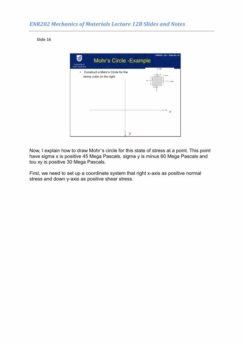
• Construct a Mohr’s Circle for the
stress cube on the right:
ENR202 12b -- Slide No. 16
x
y
Now, I explain how to draw Mohr’s circle for this state of stress at a point. This point have sigma x is positive 45 Mega Pascals, sigma y is minus 60 Mega Pascals and tou xy is positive 30 Mega Pascals. First, we need to set up a coordinate system that right x-axis as positive normal stress and down y-axis as positive shear stress.
ENR202 Mechanics of Materials Lecture 12B Slides and Notes
Slide 17
Mohr’s Circle -Example
C
-7.5 x
y
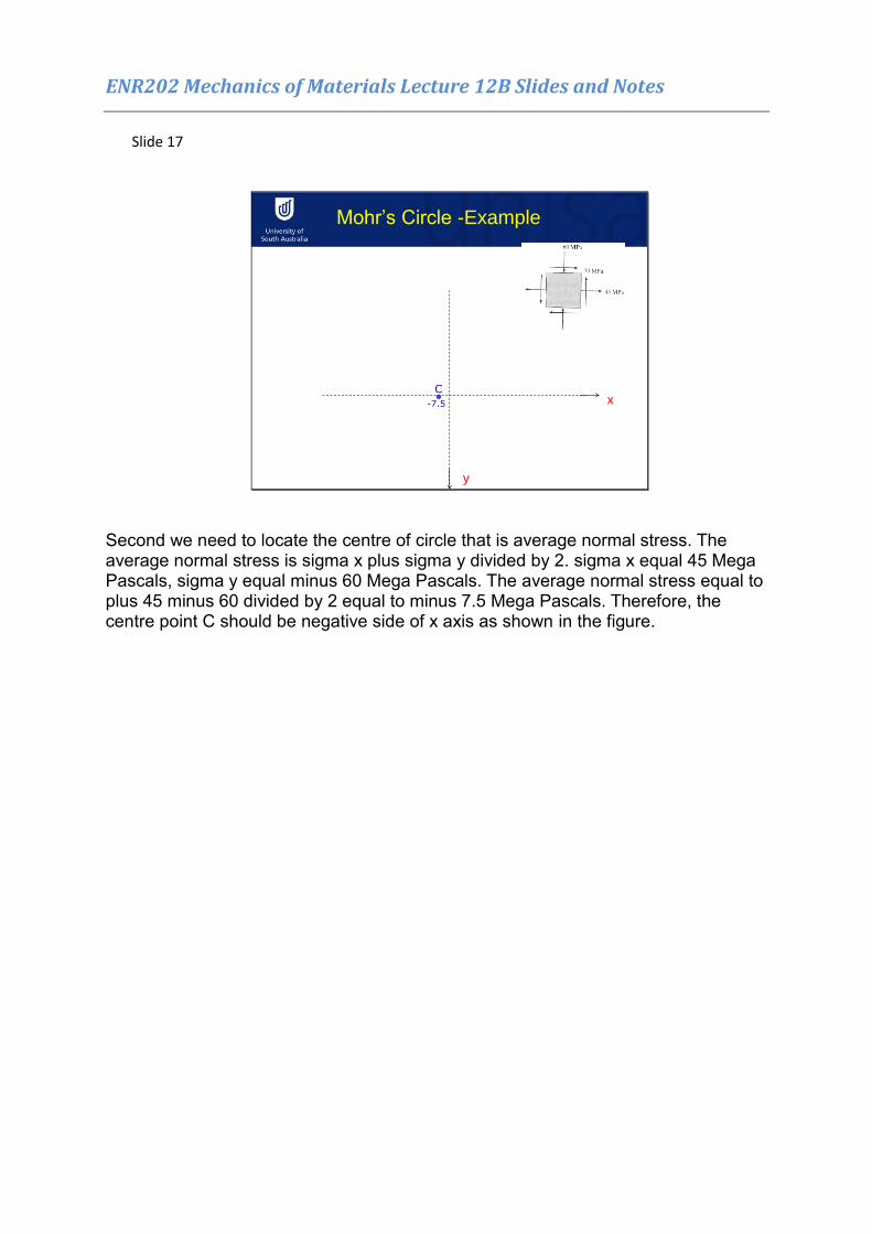
Second we need to locate the centre of circle that is average normal stress. The average normal stress is sigma x plus sigma y divided by 2. sigma x equal 45 Mega Pascals, sigma y equal minus 60 Mega Pascals. The average normal stress equal to plus 45 minus 60 divided by 2 equal to minus 7.5 Mega Pascals. Therefore, the centre point C should be negative side of x axis as shown in the figure.
ENR202 Mechanics of Materials Lecture 12B Slides and Notes
Slide 18
Mohr’s Circle -Example
C
-7.5
A
(45,30)
ENR202 12b -- Slide No. 18
x
y
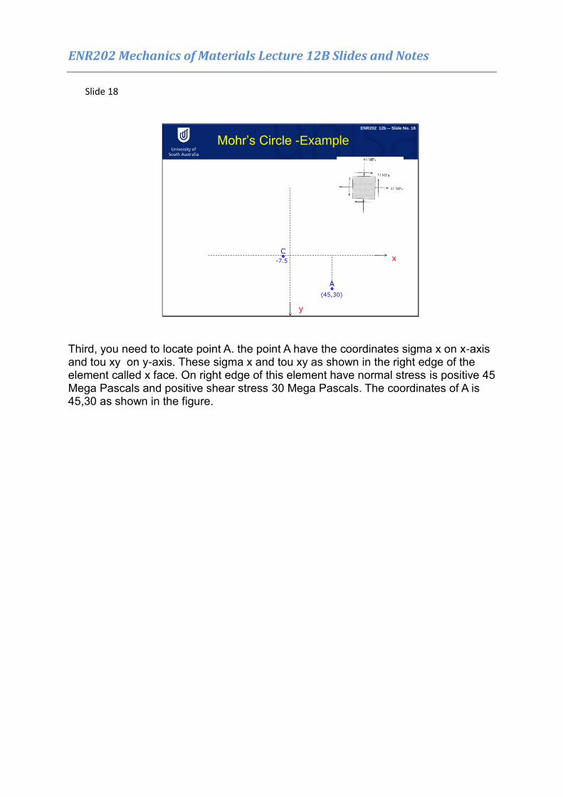
Third, you need to locate point A. the point A have the coordinates sigma x on x-axis and tou xy on y-axis. These sigma x and tou xy as shown in the right edge of the element called x face. On right edge of this element have normal stress is positive 45 Mega Pascals and positive shear stress 30 Mega Pascals. The coordinates of A is 45,30 as shown in the figure.
ENR202 Mechanics of Materials Lecture 12B Slides and Notes
Slide 19
Mohr’s Circle -Example
C
-7.5
A
(45,30)
G
(-60,-30)
ENR202 12b -- Slide No. 19
x
y
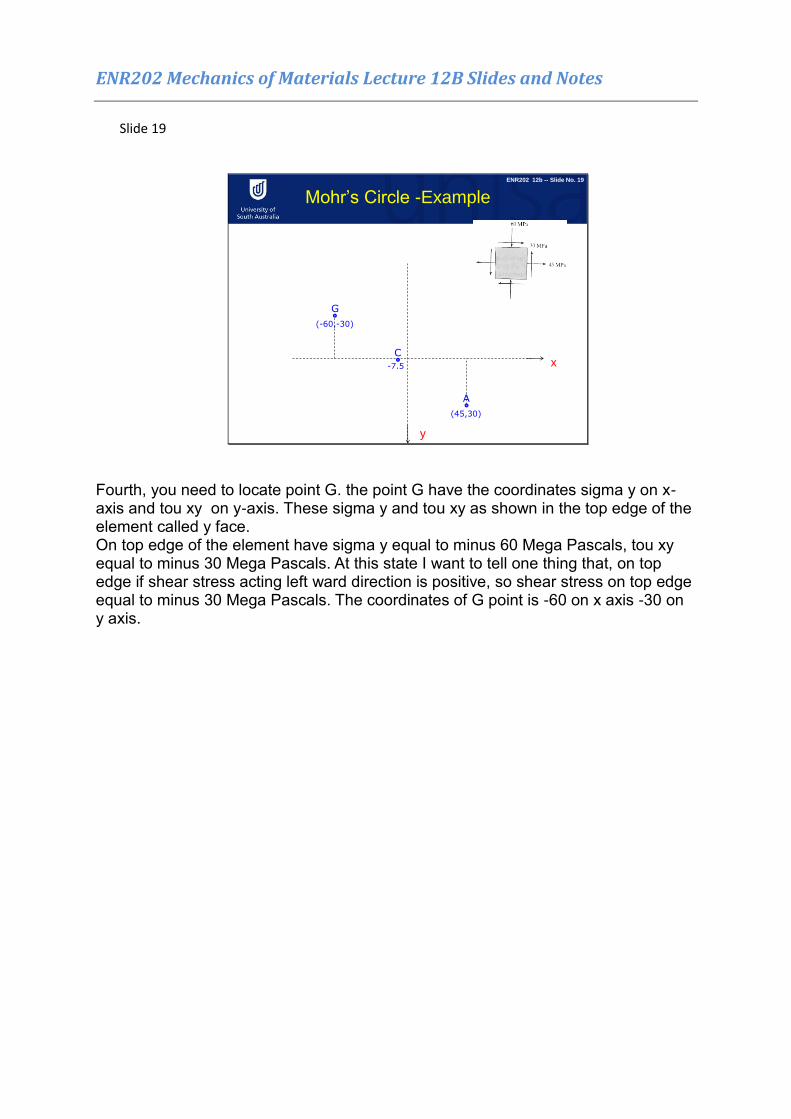
Fourth, you need to locate point G. the point G have the coordinates sigma y on x-axis and tou xy on y-axis. These sigma y and tou xy as shown in the top edge of the element called y face. On top edge of the element have sigma y equal to minus 60 Mega Pascals, tou xy equal to minus 30 Mega Pascals. At this state I want to tell one thing that, on top edge if shear stress acting left ward direction is positive, so shear stress on top edge equal to minus 30 Mega Pascals. The coordinates of G point is -60 on x axis -30 on y axis.
ENR202 Mechanics of Materials Lecture 12B Slides and Notes
Slide 20
Mohr’s Circle -Example
• Construct a Mohr’s Circle for the
stress cube on the right:
C
-7.5
A
(45,30)
G
(-60,-30)
2
ENR202 12b -- Slide No. 20
x
y
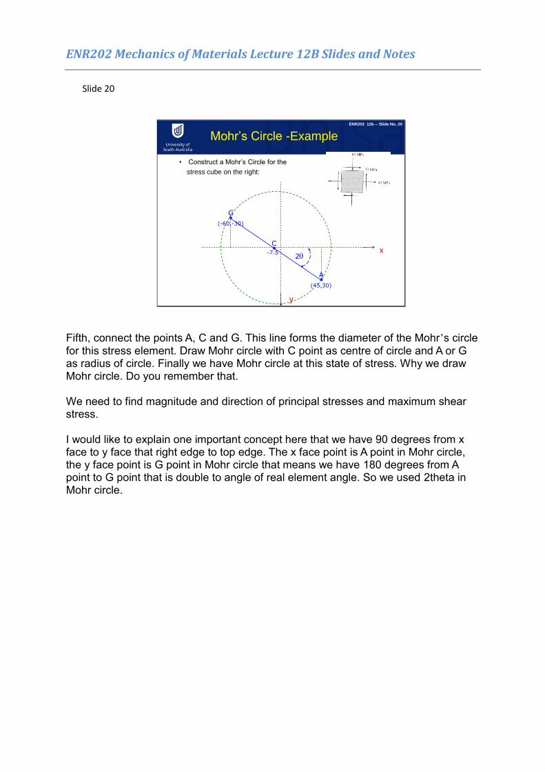
Fifth, connect the points A, C and G. This line forms the diameter of the Mohr’s circle for this stress element. Draw Mohr circle with C point as centre of circle and A or G as radius of circle. Finally we have Mohr circle at this state of stress. Why we draw Mohr circle. Do you remember that. We need to find magnitude and direction of principal stresses and maximum shear stress. I would like to explain one important concept here that we have 90 degrees from x face to y face that right edge to top edge. The x face point is A point in Mohr circle, the y face point is G point in Mohr circle that means we have 180 degrees from A point to G point that is double to angle of real element angle. So we used 2theta in Mohr circle.
ENR202 Mechanics of Materials Lecture 12B Slides and Notes
Slide 21
Principle Stresses
C
-7.5
A
(45,30)
G
(-60,-30)
2p
Principle Stress
σ1
Principle Stress
σ2
Maximum Shear = R
2
xy
2yx)
2(R
)(
Tan2avx
xy1
R
R
av2
av1
ENR202 12b -- Slide No. 21
x
y
P1
P2
S1
S2
2s
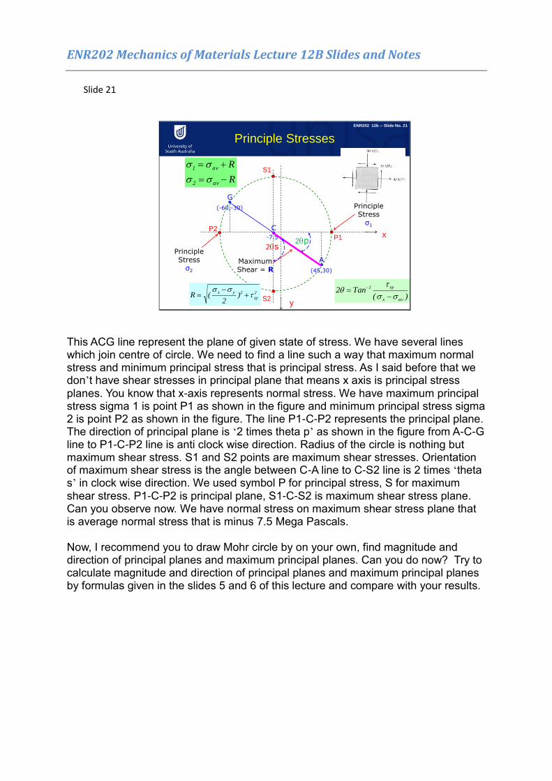
This ACG line represent the plane of given state of stress. We have several lines which join centre of circle. We need to find a line such a way that maximum normal stress and minimum principal stress that is principal stress. As I said before that we don’t have shear stresses in principal plane that means x axis is principal stress planes. You know that x-axis represents normal stress. We have maximum principal stress sigma 1 is point P1 as shown in the figure and minimum principal stress sigma 2 is point P2 as shown in the figure. The line P1-C-P2 represents the principal plane. The direction of principal plane is ‘2 times theta p’ as shown in the figure from A-C-G line to P1-C-P2 line is anti clock wise direction. Radius of the circle is nothing but maximum shear stress. S1 and S2 points are maximum shear stresses. Orientation of maximum shear stress is the angle between C-A line to C-S2 line is 2 times ‘theta s’ in clock wise direction. We used symbol P for principal stress, S for maximum shear stress. P1-C-P2 is principal plane, S1-C-S2 is maximum shear stress plane. Can you observe now. We have normal stress on maximum shear stress plane that is average normal stress that is minus 7.5 Mega Pascals. Now, I recommend you to draw Mohr circle by on your own, find magnitude and direction of principal planes and maximum principal planes. Can you do now? Try to calculate magnitude and direction of principal planes and maximum principal planes by formulas given in the slides 5 and 6 of this lecture and compare with your results.
ENR202 Mechanics of Materials Lecture 12B Slides and Notes
Slide 22
Mohr's Circle - Plane Stress
ENR202 12b -- Slide No. 22
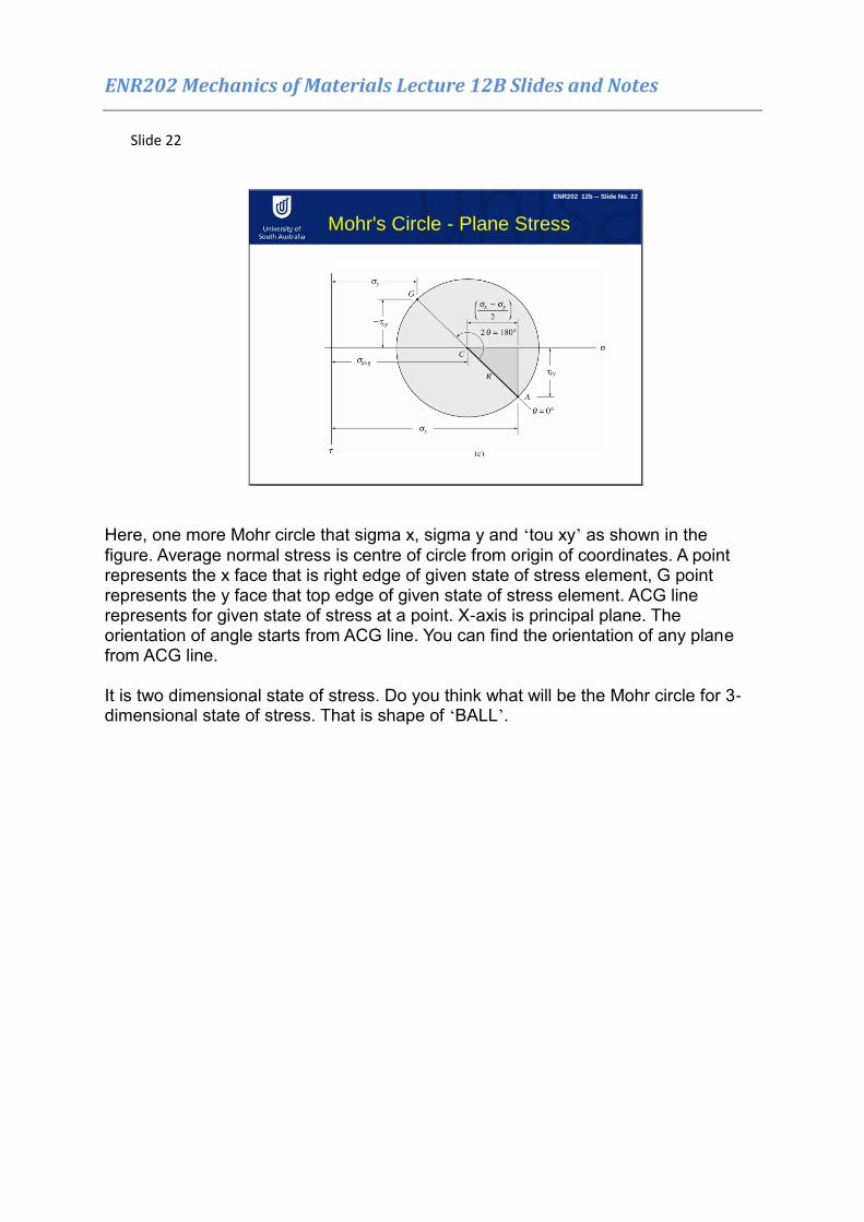
Here, one more Mohr circle that sigma x, sigma y and ‘tou xy’ as shown in the figure. Average normal stress is centre of circle from origin of coordinates. A point represents the x face that is right edge of given state of stress element, G point represents the y face that top edge of given state of stress element. ACG line represents for given state of stress at a point. X-axis is principal plane. The orientation of angle starts from ACG line. You can find the orientation of any plane from ACG line. It is two dimensional state of stress. Do you think what will be the Mohr circle for 3-dimensional state of stress. That is shape of ‘BALL’.
ENR202 Mechanics of Materials Lecture 12B Slides and Notes
Slide 23
THANK YOU
ENR202 12b -- Slide No. 23
Thank you for your attention. Now we finished Mechanics and structures. All the best for your final exam.


