Embed Size (px)
Citation preview
User Manual Please read the Important Notice and Warnings at the end of this document <Revision 1.2>
www.infineon.com <2018-06-27>
AN2017-13 EVAL-M1-183M User Manual
EVAL-M1-183M User Manual
iMOTION™ Modular Application Design Kit
About this document
Scope and purpose
This application note provides an overview of the evaluation board EVAL-M1-183M including its main features,
key data, pin assignments, mechanical dimensions and its application.
EVAL-M1-183M is an evaluation-board as part of the iMOTION™ Modular Application Design Kit (MADK). This
board features and demonstrates Infineon’s advanced Motion Control Engine (MCE) for permanent magnet
motors drive over the full speed range.
The evaluation board EVAL-M1-183M was developed to support customers during their first steps designing
applications with running any permanent magnet motor via sensorless sinusoidal control.
Intended audience
This application note is intended for all technical specialists working for motor control with the EVAL-M1-183M
board under laboratory conditions.
Table of Contents
About this document ....................................................................................................................... 1
Table of Contents ........................................................................................................................... 1
1 Safety precautions ......................................................................................................... 2
2 Introduction .................................................................................................................. 3
3 Main features ................................................................................................................ 4
3.1 Key data ................................................................................................................................................... 5
3.2 IRMCF183 installer ................................................................................................................................... 7
4 Pin assignments ............................................................................................................ 8
5 Getting Started with EVAL-M1-183M ............................................................................... 10
5.1 Setting up the system............................................................................................................................ 10
5.2 iMOTION™ development tools and software ....................................................................................... 12
5.2.1 MCEProgrammer setup overview .................................................................................................... 12
5.2.2 MCEWizard setup overview .............................................................................................................. 14
5.2.3 MCEDesigner setup overview .......................................................................................................... 16
6 Schematics and Layout .................................................................................................. 17
6.1 IRMCF183M Schematic Overview .......................................................................................................... 17
6.2 Current feedback ................................................................................................................................... 18
6.3 AD port Input ......................................................................................................................................... 19
6.4 PCB Layout ............................................................................................................................................ 20
7 Bill of Materials of EVAL-M1-183M ................................................................................... 23
8 Reference .................................................................................................................... 25
Revision History ............................................................................................................................ 26

User Manual 2 <Revision 1.2>
<2018-06-27>
EVAL-M1-183M User Manual iMOTION™ Modular Application Design Kit
Safety precautions
1 Safety precautions
In addition to the precautions listed throughout this manual, please read and understand the following
statements regarding hazards associated with development systems.
Table 1 Precautions
Attention: The ground potential of the EVAL-M1-183M system is biased to a negative DC
bus voltage potential. When measuring voltage waveform by oscilloscope, the scope’s
ground needs to be isolated. Failure to do so may result in equipment damage or
personal injury or death.
Attention: Only personnel familiar with the drive and associated machinery should plan
or implement the installation, start-up and subsequent maintenance of the system.
Failure to comply may result in personal injury and/or equipment damage.
Attention: The surfaces of the drive may become hot, which may cause injury.
Attention: EVAL-M1-183M system contains parts and assemblies sensitive to Electrostatic
Discharge (ESD). Electrostatic control precautions are required when installing, testing,
servicing or repairing this assembly. Component damage may result if ESD control
procedures are not followed. If you are not familiar with electrostatic control procedures,
refer to applicable ESD protection handbooks and guidelines.
Attention: A control board, incorrectly applied or installed, can result in component
damage or reduction in product lifetime. Wiring or application errors such as under sizing
the motor, supplying an incorrect or inadequate DC supply or excessive ambient
temperatures may result in system malfunction.
Attention: Remove or connect this control board from or to the power drive. Wait three
minutes after removing power from the power drive to discharge the bus capacitors. Do
not attempt to service the drive until the bus capacitors have discharged to zero. Failure
to do so may result in personal injury or death.
Attention: EVAL-M1-183M system is shipped with packing materials that need to be
removed prior to installation. Failure to remove all packing materials which are
unnecessary for system installation may result in overheating or abnormal operating
condition.
User Manual 3 <Revision 1.2>
<2018-06-27>
EVAL-M1-183M User Manual iMOTION™ Modular Application Design Kit
Introduction
2 Introduction
The EVAL-M1-183M evaluation board is a part of the iMOTION™ Modular Application Design Kit for drives
(iMOTION™ MADK). It is single PM motor control solution.
The MADK platform is intended to use various power stages with different control boards. These boards can
easily be interfaced through the 20 pins iMOTION™ MADK-M1 or the 30 pins iMOTION™ MADK-M3 interface
connector. This board is equipped with 20 pins connector.
This evaluation board is designed to give comprehensible solutions of sensorless control of permanent magnet
motors over the full speed range. It provides a capable of 3-phase and three types of 2-phase modulation, JTAG
and UART interface, isolated via opto-isolation box (MCETOOLV2.0), 3.3V single supply. This evaluation board is
used with Isolation box (MCETOOL V2). Details of isolation box please refer to its Application Note.
The EVAL-M1-183M evaluation board is available from Infineon. The features of this board are described in the
design feature chapter of this document, whereas the remaining paragraphs provide information to enable the
customers to copy, modify and qualify the design for production according to their own specific requirements.
Environmental conditions were considered in the design of the EVAL-M1-183M. The design was tested as
described in this document but not qualified regarding safety requirements or manufacturing and operation
over the whole operating temperature range or lifetime. The boards provided by Infineon are subject to
functional testing only.
Evaluation boards are not subject to the same procedures as regular products regarding Returned Material
Analysis (RMA), Process Change Notification (PCN) and Product Discontinuation (PD). Evaluation boards are
intended to be used under laboratory conditions by specialists only.
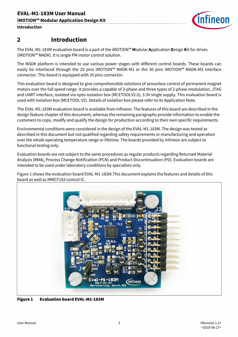
Figure 1 shows the evaluation board EVAL-M1-183M.This document explains the features and details of this
board as well as IRMCF183 control IC.
Figure 1 Evaluation board EVAL-M1-183M

User Manual 4 <Revision 1.2>
<2018-06-27>
EVAL-M1-183M User Manual iMOTION™ Modular Application Design Kit
Main features
3 Main features
EVAL-M1-183M is a control evaluation board for motor control application. The kit demonstrates Infineon’s
motion control IC technology.
Main features of Motion Control IC are:
• MCETM (Flexible Motion Control Engine) - Dedicated computation engine for high efficiency sinusoidal
sensorless motor control
• Built-in hardware peripheral for single shunt or leg shunt current feedback reconstruction and analog
circuits
• Embedded 8-bit high speed microcontroller (8051) for flexible I/O and man-machine control
• JTAG programming port for emulation/debugger
• Serial communication interface (UART)
• Watchdog timer with independent internal clock
• Internal 64Kbyte Flash
• 3.3V single supply
The evaluation board characteristics are:
• Complete kit for running any permanent magnet motor via sensorless sinusoidal control
• 3.3V single power supply
• JTAG and UART interface, isolated via opto-isolation box
• 20 pins connector
• RoHS compliant
• PCB is 45x 45 mm and has two layers with 35 μm copper each
User Manual 5 <Revision 1.2>
<2018-06-27>
EVAL-M1-183M User Manual iMOTION™ Modular Application Design Kit
Main features
3.1 Key data
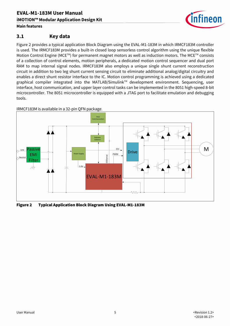
Figure 2 provides a typical application Block Diagram using the EVAL-M1-183M in which IRMCF183M controller
is used. The IRMCF183M provides a built-in closed loop sensorless control algorithm using the unique flexible
Motion Control Engine (MCETM) for permanent magnet motors as well as induction motors. The MCETM consists
of a collection of control elements, motion peripherals, a dedicated motion control sequencer and dual port
RAM to map internal signal nodes. IRMCF183M also employs a unique single shunt current reconstruction
circuit in addition to two leg shunt current sensing circuit to eliminate additional analog/digital circuitry and
enables a direct shunt resistor interface to the IC. Motion control programming is achieved using a dedicated
graphical compiler integrated into the MATLAB/SimulinkTM development environment. Sequencing, user
interface, host communication, and upper layer control tasks can be implemented in the 8051 high-speed 8-bit
microcontroller. The 8051 microcontroller is equipped with a JTAG port to facilitate emulation and debugging
tools.
IRMCF183M is available in a 32-pin QFN package.
MPassiveEMI
Filter
Drive
EVAL-M1-183M
Power Supply
Line
Neutral
PWM
3.3V
GalvanicIsolation
HostCommunication
15V
DC
Bse
nse
Figure 2 Typical Application Block Diagram Using EVAL-M1-183M
User Manual 6 <Revision 1.2>
<2018-06-27>
EVAL-M1-183M User Manual iMOTION™ Modular Application Design Kit
Main features
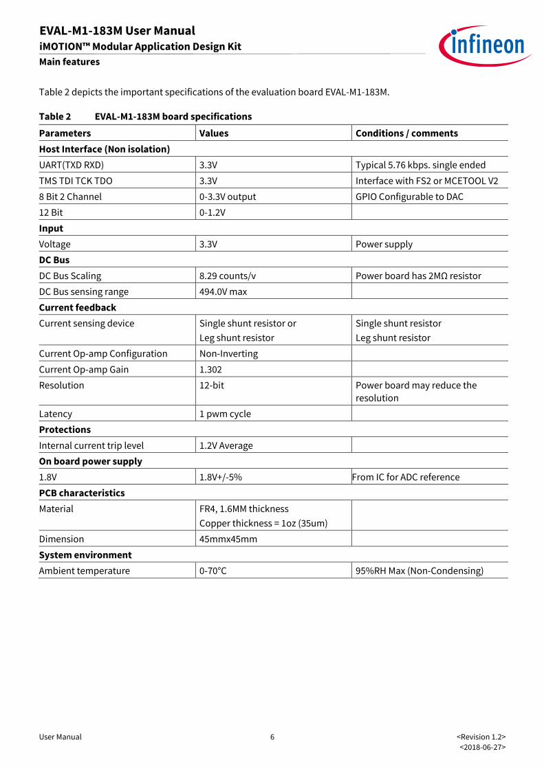
Table 2 depicts the important specifications of the evaluation board EVAL-M1-183M.
Table 2 EVAL-M1-183M board specifications
Parameters Values Conditions / comments
Host Interface (Non isolation)
UART(TXD RXD) 3.3V Typical 5.76 kbps. single ended
TMS TDI TCK TDO 3.3V Interface with FS2 or MCETOOL V2
8 Bit 2 Channel 0-3.3V output GPIO Configurable to DAC
12 Bit 0-1.2V
Input
Voltage 3.3V Power supply
DC Bus
DC Bus Scaling 8.29 counts/v Power board has 2MΩ resistor
DC Bus sensing range 494.0V max
Current feedback
Current sensing device Single shunt resistor or
Leg shunt resistor
Single shunt resistor
Leg shunt resistor
Current Op-amp Configuration Non-Inverting
Current Op-amp Gain 1.302
Resolution 12-bit Power board may reduce the
resolution
Latency 1 pwm cycle
Protections
Internal current trip level 1.2V Average
On board power supply
1.8V 1.8V+/-5% From IC for ADC reference
PCB characteristics
Material FR4, 1.6MM thickness
Copper thickness = 1oz (35um)
Dimension 45mmx45mm
System environment
Ambient temperature 0-70°C 95%RH Max (Non-Condensing)
User Manual 7 <Revision 1.2>
<2018-06-27>
EVAL-M1-183M User Manual iMOTION™ Modular Application Design Kit
Main features
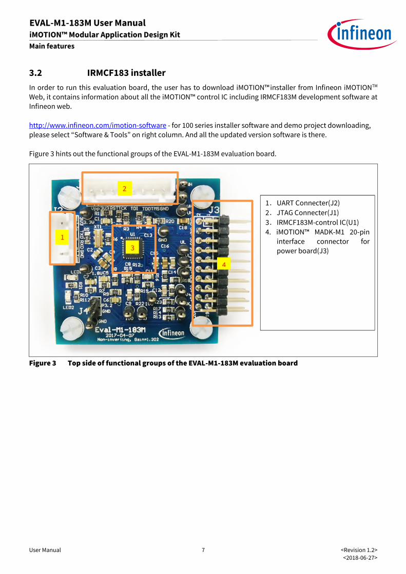
3.2 IRMCF183 installer
In order to run this evaluation board, the user has to download iMOTION™ installer from Infineon iMOTIONTM
Web, it contains information about all the iMOTION™ control IC including IRMCF183M development software at
Infineon web.
http://www.infineon.com/imotion-software - for 100 series installer software and demo project downloading,
please select “Software & Tools” on right column. And all the updated version software is there.
Figure 3 hints out the functional groups of the EVAL-M1-183M evaluation board.
Figure 3 Top side of functional groups of the EVAL-M1-183M evaluation board
1
2
3
4
1.UART Connecter(J2)
2.JTAG Connecter(J1)
3.IRMCF183M-control IC(U1)
4. iMOTION™ MADK-M1 20-pin
interface connector for
power board(J3)
User Manual 8 <Revision 1.2>
<2018-06-27>
EVAL-M1-183M User Manual iMOTION™ Modular Application Design Kit
Pin assignments
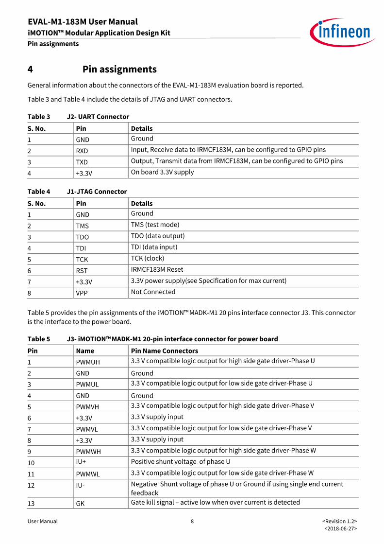
4 Pin assignments
General information about the connectors of the EVAL-M1-183M evaluation board is reported.
Table 3 and Table 4 include the details of JTAG and UART connectors.
Table 3 J2- UART Connector
S. No. Pin Details
1 GND Ground
2 RXD Input, Receive data to IRMCF183M, can be configured to GPIO pins
3 TXD Output, Transmit data from IRMCF183M, can be configured to GPIO pins
4 +3.3V On board 3.3V supply
Table 4 J1-JTAG Connector
S. No. Pin Details
1 GND Ground
2 TMS TMS (test mode)
3 TDO TDO (data output)
4 TDI TDI (data input)
5 TCK TCK (clock)
6 RST IRMCF183M Reset
7 +3.3V 3.3V power supply(see Specification for max current)
8 VPP Not Connected
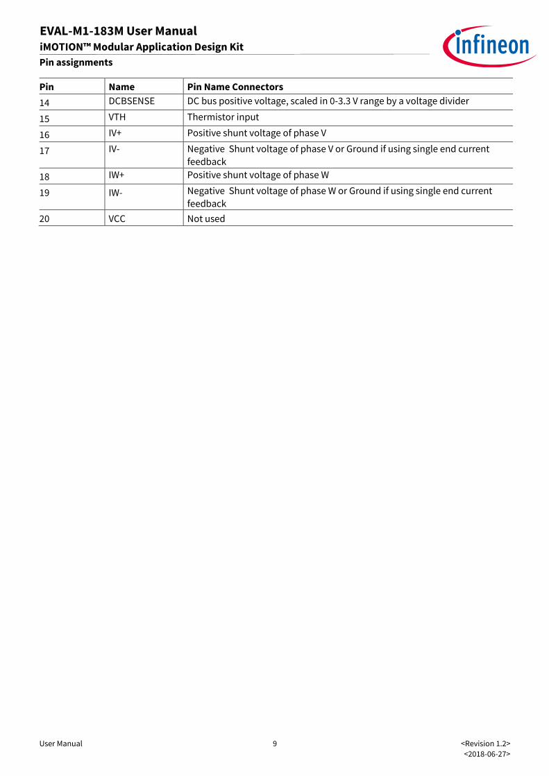
Table 5 provides the pin assignments of the iMOTION™MADK-M1 20 pins interface connector J3. This connector
is the interface to the power board.
Table 5 J3- iMOTION™MADK-M1 20-pin interface connector for power board
Pin Name Pin Name Connectors
1 PWMUH 3.3 V compatible logic output for high side gate driver-Phase U
2 GND Ground
3 PWMUL 3.3 V compatible logic output for low side gate driver-Phase U
4 GND Ground
5 PWMVH 3.3 V compatible logic output for high side gate driver-Phase V
6 +3.3V 3.3 V supply input
7 PWMVL 3.3 V compatible logic output for low side gate driver-Phase V
8 +3.3V 3.3 V supply input
9 PWMWH 3.3 V compatible logic output for high side gate driver-Phase W
10 IU+ Positive shunt voltage of phase U
11 PWMWL 3.3 V compatible logic output for low side gate driver-Phase W
12 IU- Negative Shunt voltage of phase U or Ground if using single end current
feedback
13 GK Gate kill signal – active low when over current is detected
User Manual 9 <Revision 1.2>
<2018-06-27>
EVAL-M1-183M User Manual iMOTION™ Modular Application Design Kit
Pin assignments
Pin Name Pin Name Connectors
14 DCBSENSE DC bus positive voltage, scaled in 0-3.3 V range by a voltage divider
15 VTH Thermistor input
16 IV+ Positive shunt voltage of phase V
17 IV- Negative Shunt voltage of phase V or Ground if using single end current
feedback
18 IW+ Positive shunt voltage of phase W
19 IW- Negative Shunt voltage of phase W or Ground if using single end current
feedback
20 VCC Not used
User Manual 10 <Revision 1.2>
<2018-06-27>
EVAL-M1-183M User Manual iMOTION™ Modular Application Design Kit
Getting Started with EVAL-M1-183M
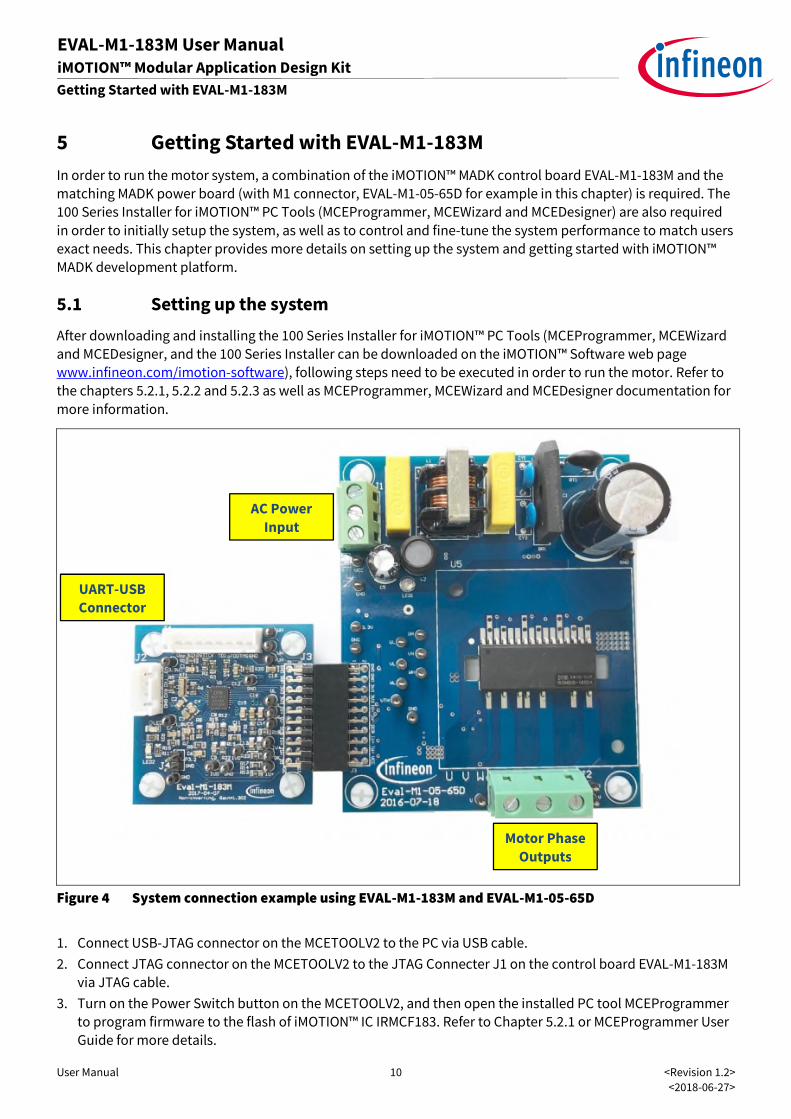
5 Getting Started with EVAL-M1-183M
In order to run the motor system, a combination of the iMOTION™ MADK control board EVAL-M1-183M and the
matching MADK power board (with M1 connector, EVAL-M1-05-65D for example in this chapter) is required. The
100 Series Installer for iMOTION™ PC Tools (MCEProgrammer, MCEWizard and MCEDesigner) are also required
in order to initially setup the system, as well as to control and fine-tune the system performance to match users
exact needs. This chapter provides more details on setting up the system and getting started with iMOTION™
MADK development platform.
5.1 Setting up the system
After downloading and installing the 100 Series Installer for iMOTION™ PC Tools (MCEProgrammer, MCEWizard
and MCEDesigner, and the 100 Series Installer can be downloaded on the iMOTION™ Software web page
www.infineon.com/imotion-software), following steps need to be executed in order to run the motor. Refer to
the chapters 5.2.1, 5.2.2 and 5.2.3 as well as MCEProgrammer, MCEWizard and MCEDesigner documentation for
more information.
Figure 4 System connection example using EVAL-M1-183M and EVAL-M1-05-65D
1. Connect USB-JTAG connector on the MCETOOLV2 to the PC via USB cable.
2. Connect JTAG connector on the MCETOOLV2 to the JTAG Connecter J1 on the control board EVAL-M1-183M
via JTAG cable.
3. Turn on the Power Switch button on the MCETOOLV2, and then open the installed PC tool MCEProgrammer
to program firmware to the flash of iMOTION™ IC IRMCF183. Refer to Chapter 5.2.1 or MCEProgrammer User
Guide for more details.
UART-USB
Connector
Motor Phase
Outputs
AC Power
Input

User Manual 11 <Revision 1.2>
<2018-06-27>
EVAL-M1-183M User Manual iMOTION™ Modular Application Design Kit
Getting Started with EVAL-M1-183M
4. Connect EVAL-M1-183M’s M1 20-pin interface connector (J3) to power board (For example EVAL-M1-05-65D,
see Figure 4).
5. Connect USB-UART connector on the MCETOOLV2 to the PC via USB cable.
6. Connect UART connector on the MCETOOLV2 to the UART Connecter J2 on the control board EVAL-M1-183M
via UART cable.
7. Use MCEWizard to enter the target motor’s system and operating parameters, as well as evaluation board’s
hardware parameters, which will then be used to calculate controller’s digital parameter set representing
complete motor drive system. First click “Calculate” button on the “Verify & Save Page” and then save the
drive parameter set into your project directory by clicking “Export to Designer file (.txt)”. Saved Drive
System Parameter File will be later used by the MCEDesigner. Refer to Chapter 5.2.2 or MCEWizard User
Guide for more details.
8. Connect motor phase outputs to the motor.
9. Connect AC power to power input connector and power on system.
10. Start MCEDesigner tool and open MCEDesigner default configuration file (.irc) for IRMCF183 controller
(IRMCS1183-1-D_R35.irc) by clicking “File” > “Open”. IRMCS1183-1-D_R35.irc is included in the iMotion
default document folder “C:\Users\xxx\Documents\iMotion\IRMCS1183-1-D” after installed the 100 Series
Installer.
11. MCEDesigner should automatically connect to the EVAL-M1-101T control board using default COM port
(Indicated by green circle next to “COMx Up” status in the bottom frame of the MCEDesigner GUI). If it
cannot establish the connection, change COM port by doing following steps: (“System” window active) >
Preferences > Connection > Connect using (Chose one of the other available COM ports from the drop-down
menu).
12. Use following steps to import the drive parameters into the internal SRAM of iMOTION™ IC: Click “File” and
select “Import Drive Parameters”. Browse and select the Drive Parameters .txt file created in step 7, and
finally Click Configure Motor button to import drive parameters. See chapter MCEDesigner setup overview
5.2.3 for more details.
13. Start the motor by clicking the green traffic light button in the control bar.
User Manual 12 <Revision 1.2>
<2018-06-27>
EVAL-M1-183M User Manual iMOTION™ Modular Application Design Kit
Getting Started with EVAL-M1-183M
5.2 iMOTION™ development tools and software
The 100 Series Installer for iMOTION™Development Tools MCEProgrammer, MCEDesigner and MCEWizard are
available for download via Infineon iMOTIONTM website (http://www.infineon.com/imotion-software). All
supported tools and software variants are listed there. Please visit this page periodically to check for
tool/software updates.
5.2.1 MCEProgrammer setup overview
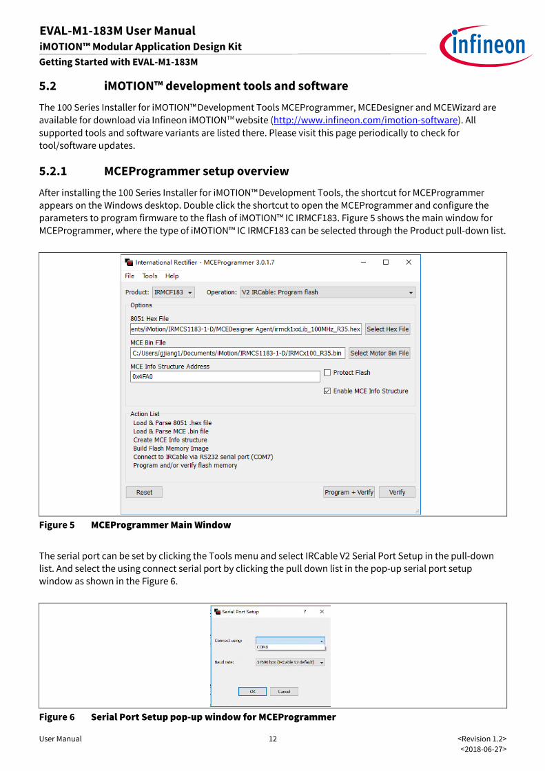
After installing the 100 Series Installer for iMOTION™Development Tools, the shortcut for MCEProgrammer
appears on the Windows desktop. Double click the shortcut to open the MCEProgrammer and configure the
parameters to program firmware to the flash of iMOTION™ IC IRMCF183. Figure 5 shows the main window for
MCEProgrammer, where the type of iMOTION™ IC IRMCF183 can be selected through the Product pull-down list.
Figure 5 MCEProgrammer Main Window
The serial port can be set by clicking the Tools menu and select IRCable V2 Serial Port Setup in the pull-down
list. And select the using connect serial port by clicking the pull down list in the pop-up serial port setup
window as shown in the Figure 6.
Figure 6 Serial Port Setup pop-up window for MCEProgrammer
User Manual 13 <Revision 1.2>
<2018-06-27>
EVAL-M1-183M User Manual iMOTION™ Modular Application Design Kit
Getting Started with EVAL-M1-183M
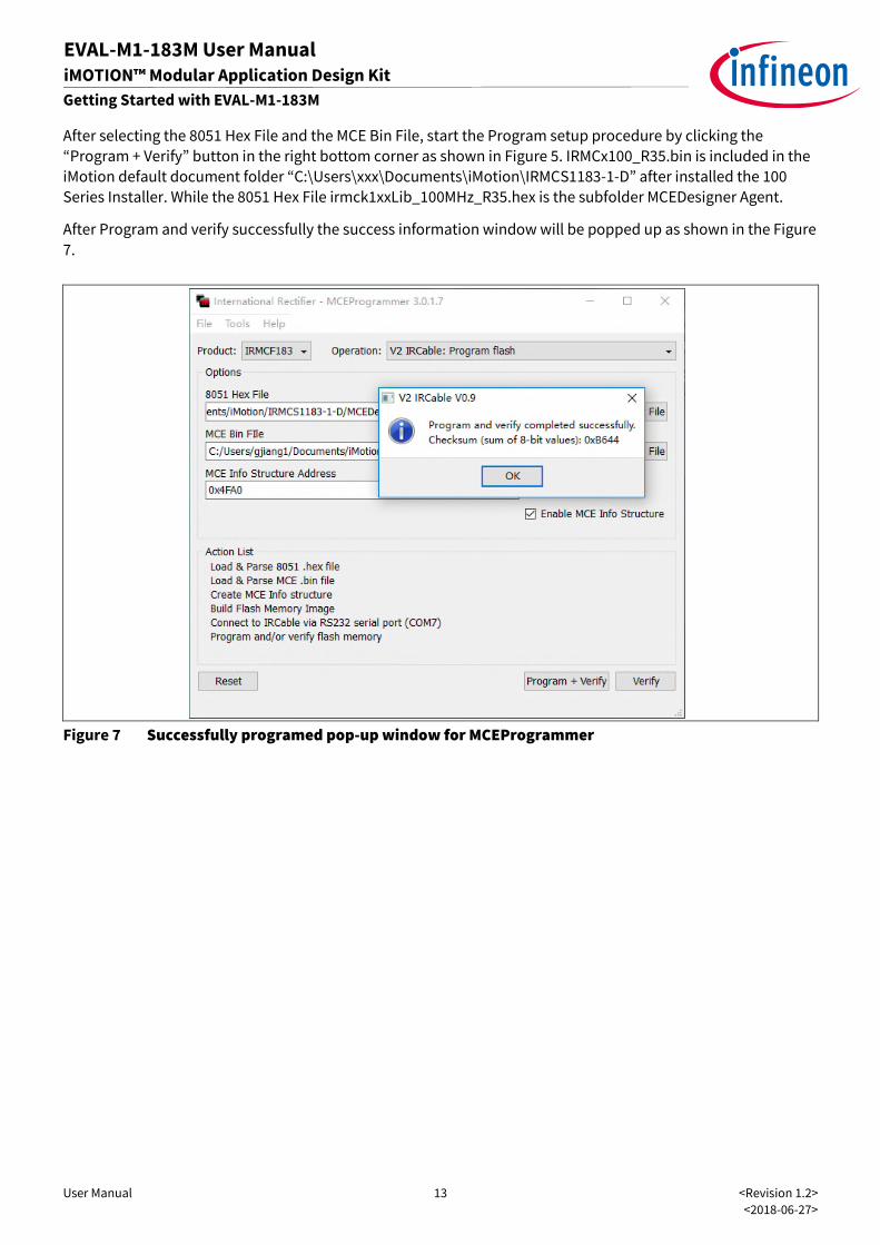
After selecting the 8051 Hex File and the MCE Bin File, start the Program setup procedure by clicking the
“Program + Verify” button in the right bottom corner as shown in Figure 5. IRMCx100_R35.bin is included in the
iMotion default document folder “C:\Users\xxx\Documents\iMotion\IRMCS1183-1-D” after installed the 100
Series Installer. While the 8051 Hex File irmck1xxLib_100MHz_R35.hex is the subfolder MCEDesigner Agent.
After Program and verify successfully the success information window will be popped up as shown in the Figure
7.
Figure 7 Successfully programed pop-up window for MCEProgrammer
User Manual 14 <Revision 1.2>
<2018-06-27>
EVAL-M1-183M User Manual iMOTION™ Modular Application Design Kit
Getting Started with EVAL-M1-183M
5.2.2 MCEWizard setup overview
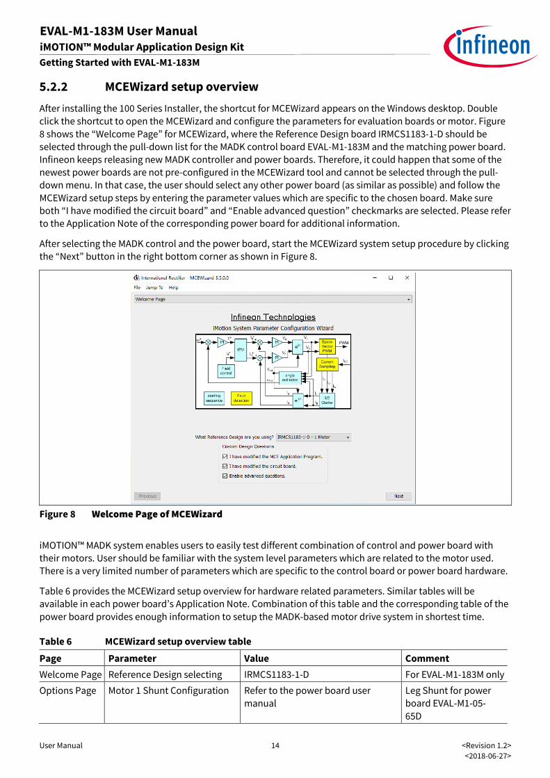
After installing the 100 Series Installer, the shortcut for MCEWizard appears on the Windows desktop. Double
click the shortcut to open the MCEWizard and configure the parameters for evaluation boards or motor. Figure
8 shows the “Welcome Page” for MCEWizard, where the Reference Design board IRMCS1183-1-D should be
selected through the pull-down list for the MADK control board EVAL-M1-183M and the matching power board.
Infineon keeps releasing new MADK controller and power boards. Therefore, it could happen that some of the
newest power boards are not pre-configured in the MCEWizard tool and cannot be selected through the pull-
down menu. In that case, the user should select any other power board (as similar as possible) and follow the
MCEWizard setup steps by entering the parameter values which are specific to the chosen board. Make sure
both “I have modified the circuit board” and “Enable advanced question” checkmarks are selected. Please refer
to the Application Note of the corresponding power board for additional information.
After selecting the MADK control and the power board, start the MCEWizard system setup procedure by clicking
the “Next” button in the right bottom corner as shown in Figure 8.
Figure 8 Welcome Page of MCEWizard
iMOTION™ MADK system enables users to easily test different combination of control and power board with
their motors. User should be familiar with the system level parameters which are related to the motor used.
There is a very limited number of parameters which are specific to the control board or power board hardware.
Table 6 provides the MCEWizard setup overview for hardware related parameters. Similar tables will be
available in each power board’s Application Note. Combination of this table and the corresponding table of the
power board provides enough information to setup the MADK-based motor drive system in shortest time.
Table 6 MCEWizard setup overview table
Page Parameter Value Comment
Welcome Page Reference Design selecting IRMCS1183-1-D For EVAL-M1-183M only
Options Page Motor 1 Shunt Configuration Refer to the power board user
manual
Leg Shunt for power
board EVAL-M1-05-
65D
User Manual 15 <Revision 1.2>
<2018-06-27>
EVAL-M1-183M User Manual iMOTION™ Modular Application Design Kit
Getting Started with EVAL-M1-183M
Page Parameter Value Comment
Question 3 Controller Supply Voltage Refer to the power board user
manual
VDD is 3.3V by default
Question 8 Max DC Bus Voltage Refer to the power board user
manual
Question 9 DC Bus Sensing High Resistor Refer to the power board user
manual
2000 kΩ for power
board EVAL-M1-05-
65D
Question 10 DC Bus Sensing Low Resistor 4.87 kΩ
Question 111 GateSense Low-Side Devices Refer to the power board user
manual
High is true for power
board EVAL-M1-05-
65D
Question 112 GateSense High-Side Devices Refer to the power board user
manual
High is true for power
board EVAL-M1-05-
65D
Question 117 Current Feedback Shunt Refer to the power board user
manual
250mΩ for power
board EVAL-M1-05-
65D only
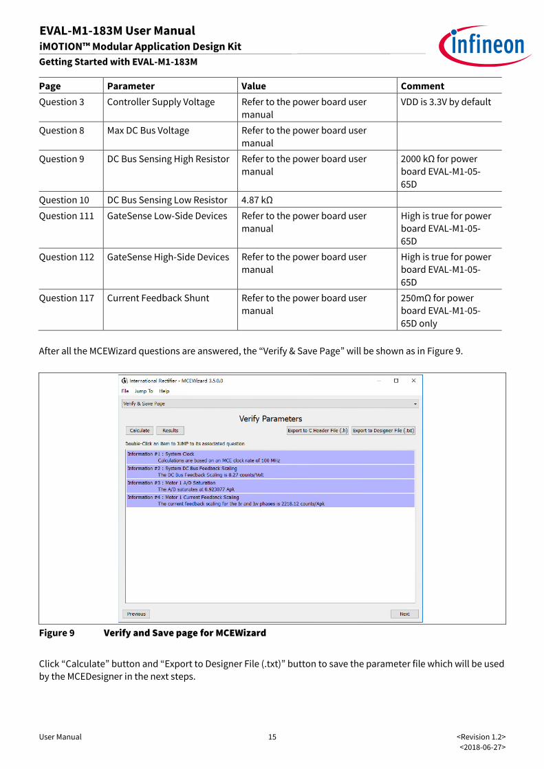
After all the MCEWizard questions are answered, the “Verify & Save Page” will be shown as in Figure 9.
Figure 9 Verify and Save page for MCEWizard
Click “Calculate” button and “Export to Designer File (.txt)” button to save the parameter file which will be used
by the MCEDesigner in the next steps.
User Manual 16 <Revision 1.2>
<2018-06-27>
EVAL-M1-183M User Manual iMOTION™ Modular Application Design Kit
Getting Started with EVAL-M1-183M
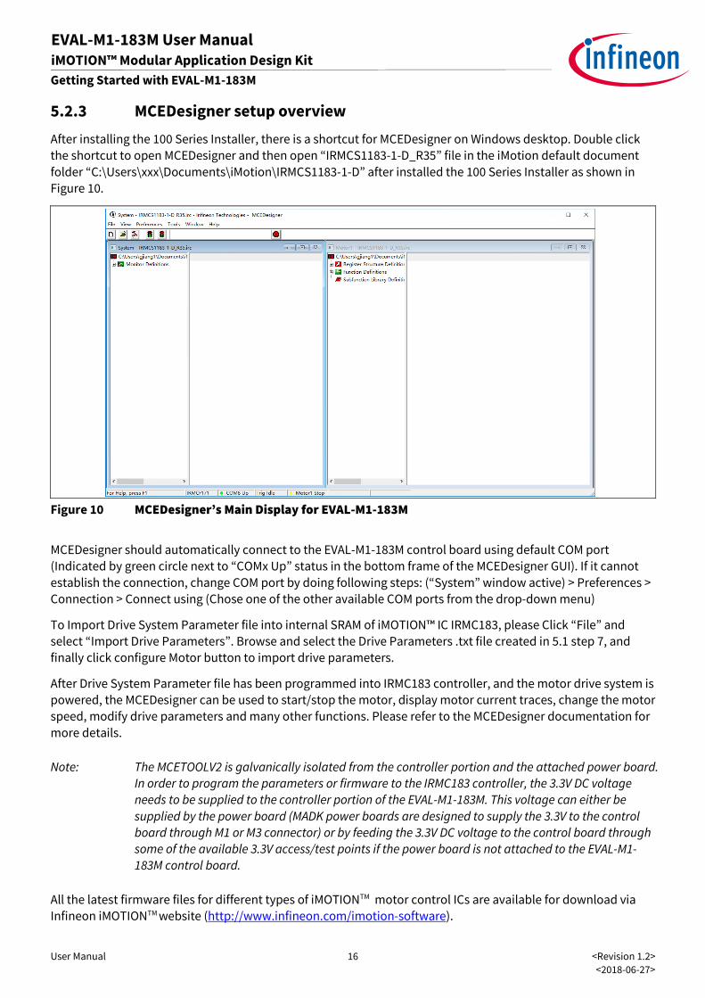
5.2.3 MCEDesigner setup overview
After installing the 100 Series Installer, there is a shortcut for MCEDesigner on Windows desktop. Double click
the shortcut to open MCEDesigner and then open “IRMCS1183-1-D_R35” file in the iMotion default document
folder “C:\Users\xxx\Documents\iMotion\IRMCS1183-1-D” after installed the 100 Series Installer as shown in
Figure 10.
Figure 10 MCEDesigner’s Main Display for EVAL-M1-183M
MCEDesigner should automatically connect to the EVAL-M1-183M control board using default COM port
(Indicated by green circle next to “COMx Up” status in the bottom frame of the MCEDesigner GUI). If it cannot
establish the connection, change COM port by doing following steps: (“System” window active) > Preferences >
Connection > Connect using (Chose one of the other available COM ports from the drop-down menu)
To Import Drive System Parameter file into internal SRAM of iMOTION™ IC IRMC183, please Click “File” and
select “Import Drive Parameters”. Browse and select the Drive Parameters .txt file created in 5.1 step 7, and
finally click configure Motor button to import drive parameters.
After Drive System Parameter file has been programmed into IRMC183 controller, and the motor drive system is
powered, the MCEDesigner can be used to start/stop the motor, display motor current traces, change the motor
speed, modify drive parameters and many other functions. Please refer to the MCEDesigner documentation for
more details.
Note: The MCETOOLV2 is galvanically isolated from the controller portion and the attached power board.
In order to program the parameters or firmware to the IRMC183 controller, the 3.3V DC voltage
needs to be supplied to the controller portion of the EVAL-M1-183M. This voltage can either be
supplied by the power board (MADK power boards are designed to supply the 3.3V to the control
board through M1 or M3 connector) or by feeding the 3.3V DC voltage to the control board through
some of the available 3.3V access/test points if the power board is not attached to the EVAL-M1-
183M control board.
All the latest firmware files for different types of iMOTIONTM motor control ICs are available for download via
Infineon iMOTIONTM website (http://www.infineon.com/imotion-software).
User Manual 17 <Revision 1.2>
<2018-06-27>
EVAL-M1-183M User Manual iMOTION™ Modular Application Design Kit
Schematics and Layout
6 Schematics and Layout
To meet individual customer requirements and make the EVAL-M1-183M evaluation board a basis for
development or modification, all necessary technical data like schematics, layout and components are
included in this chapter.
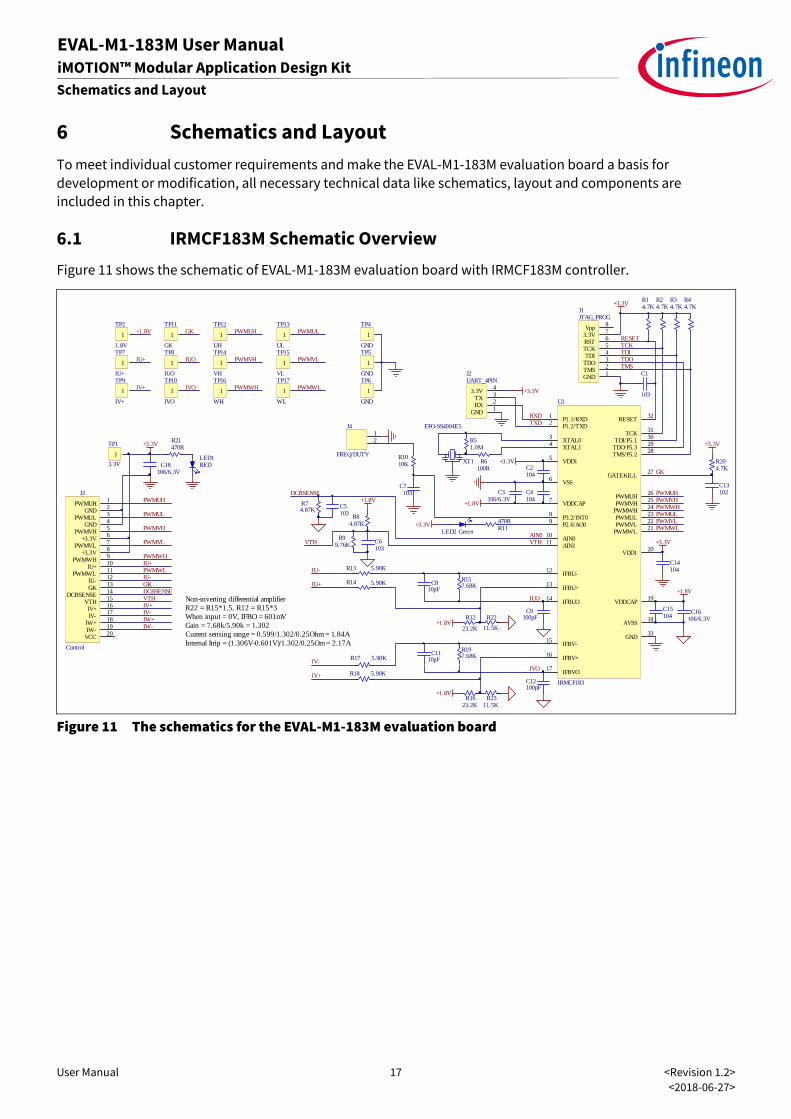
6.1 IRMCF183M Schematic Overview
Figure 11 shows the schematic of EVAL-M1-183M evaluation board with IRMCF183M controller.
Figure 11 The schematics for the EVAL-M1-183M evaluation board
C14104
C6103
C5103
R1623.2K
R14 5.90K
R12
23.2K
R157.68K
R6100R
R51.0M
C16106/6.3V
C15104
R11470R
R74.87K
C810pF
C1
103
+3.3VR14.7K
R24.7K
R34.7K
R44.7K
GND1
TMS2
TDO3
TDI4
TCK5
RST6
3.3V7
Vpp8
J1JTAG_PROG
GND1
RX2
TX3
3.3V4
J2UART_4PIN
RESETTCKTDITDOTMS
+3.3V
+1.8V
RXDTXD
VTH
+3.3V
C13102
C18106/6.3V
+1.8V
AIN0
C4104
C3106/6.3V
C2104
+3.3V
+1.8V
XT1
EFO-SS4004E5
PWMUHPWMVHPWMWHPWMULPWMVLPWMWL
GK
Non-inverting differential amplifierR22 = R15*1.5, R12 = R15*3When input = 0V, IFBO = 601mVGain = 7.68k/5.90k = 1.302Current sensing range = 0.599/1.302/0.25Ohm = 1.84AInternal Itrip = (1.306V-0.601V)/1.302/0.25Om = 2.17A
R18 5.90K
R13 5.90K
1
TP1
3.3V
RESET32
P1.1/RXD1
P1.2/TXD2
XTAL03
XTAL14
VDD15
VSS6
P3.2/INT08
P2.6/AO09
AIN111
IFBU+13
GATEKILL27
PWMUH26
IFBUO14
VDDCAP19
PWMWL21
PWMVL22
PWMUL23
PWMWH24
PWMVH25
VDD120
TDO/P5.329
TDI/P5.130
TCK31
IFBU-12
TMS/P5.228
AIN010
IFBV-15
IFBV+16
IFBVO17
AVSS18
GND33
VDDCAP7
U1
IRMCF183
+1.8V
VTH
C9100pF
IU+
IV+
R17 5.90K
R197.68K
C12100pF
C1110pF
+1.8V
LED2 Green
1
TP16
WH
1
TP13
UL
1
TP15
VL
1
TP17
WL
1
TP8
IUO
1
TP10
IVO
1
TP14
VH
1
TP12
UH
1
TP2
1.8V
1
TP7
IU+
1
TP9
IV+
1
TP11
GK
+1.8V
IU+
IV+
GK
IUO
IVO
PWMUH
PWMVH
PWMWH
PWMUL
PWMVL
PWMWL
R1010K
+3.3VR8
4.87K
1
TP4
GND
1
TP5
GND
1
TP6
GND
IUO
IVO
R99.76K
DCBSENSE
+3.3V
PWMUH
PWMUL
PWMVH
PWMVL
PWMWH
PWMWL
GK
IU+
IU-
IV+IV-
DCBSENSEVTH
IW+IW-
LED1RED
R21470R
R204.7K
+3.3V
IU-
IV-
R2311.5K
R22
11.5K
PWMUH1
GND2
PWMUL3
GND4
PWMVH5
+3.3V6
PWMVL7
+3.3V8
PWMWH9
IU+10
PWMWL11
IU-12
GK13
DCBSENSE14
VTH15
IV+16
IV-17
IW+18
IW-19
VCC20
J3
Control
C7103
12
J4
FREQ/DUTY
User Manual 18 <Revision 1.2>
<2018-06-27>
EVAL-M1-183M User Manual iMOTION™ Modular Application Design Kit
Schematics and Layout
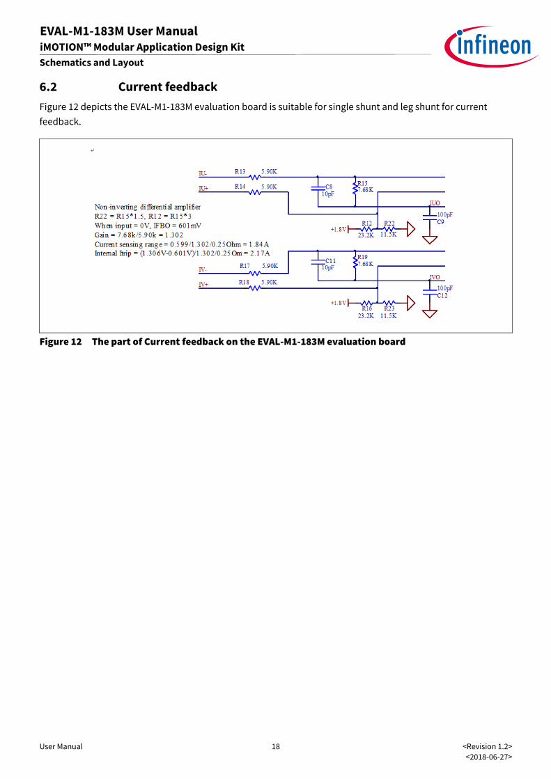
6.2 Current feedback
Figure 12 depicts the EVAL-M1-183M evaluation board is suitable for single shunt and leg shunt for current
feedback.
Figure 12 The part of Current feedback on the EVAL-M1-183M evaluation board
User Manual 19 <Revision 1.2>
<2018-06-27>
EVAL-M1-183M User Manual iMOTION™ Modular Application Design Kit
Schematics and Layout
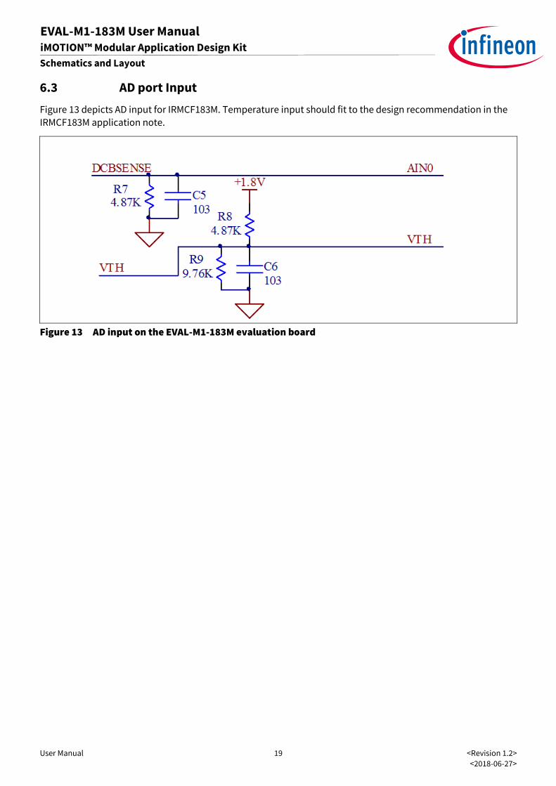
6.3 AD port Input
Figure 13 depicts AD input for IRMCF183M. Temperature input should fit to the design recommendation in the
IRMCF183M application note.
Figure 13 AD input on the EVAL-M1-183M evaluation board
User Manual 20 <Revision 1.2>
<2018-06-27>
EVAL-M1-183M User Manual iMOTION™ Modular Application Design Kit
Schematics and Layout
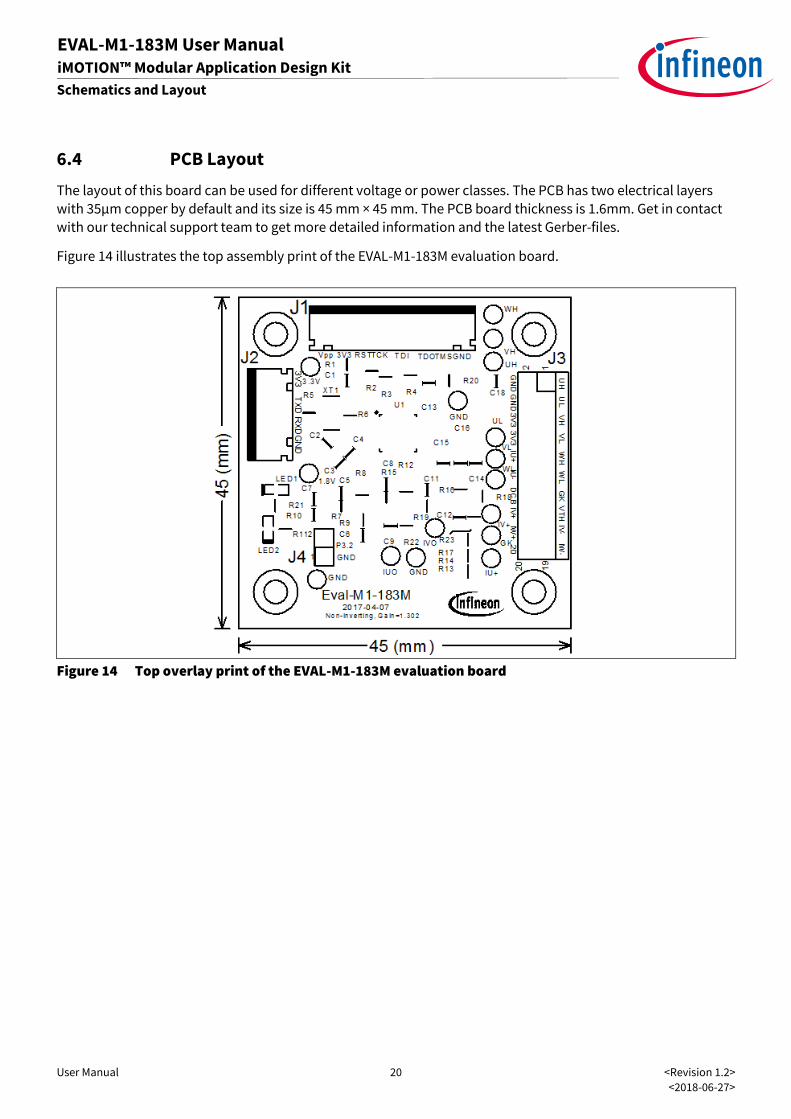
6.4 PCB Layout
The layout of this board can be used for different voltage or power classes. The PCB has two electrical layers
with 35µm copper by default and its size is 45 mm × 45 mm. The PCB board thickness is 1.6mm. Get in contact
with our technical support team to get more detailed information and the latest Gerber-files.
Figure 14 illustrates the top assembly print of the EVAL-M1-183M evaluation board.
Figure 14 Top overlay print of the EVAL-M1-183M evaluation board
User Manual 21 <Revision 1.2>
<2018-06-27>
EVAL-M1-183M User Manual iMOTION™ Modular Application Design Kit
Schematics and Layout
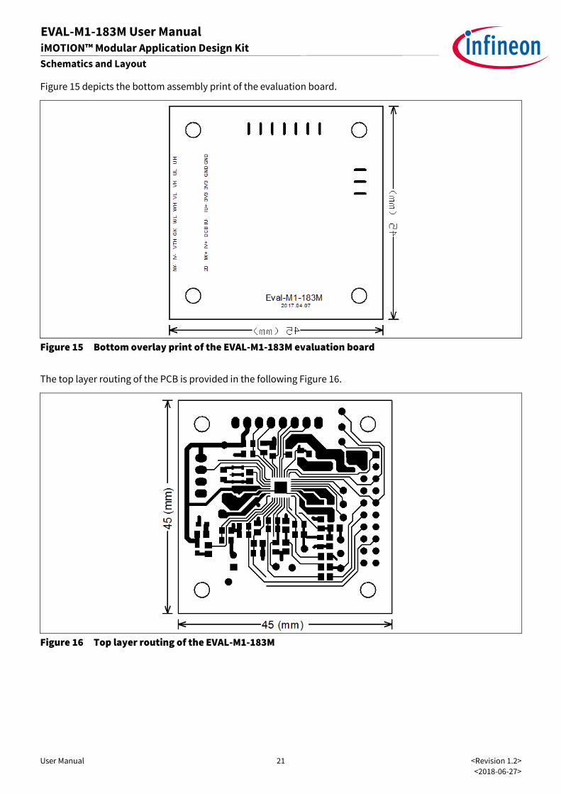
Figure 15 depicts the bottom assembly print of the evaluation board.
Figure 15 Bottom overlay print of the EVAL-M1-183M evaluation board
The top layer routing of the PCB is provided in the following Figure 16.
Figure 16 Top layer routing of the EVAL-M1-183M
User Manual 22 <Revision 1.2>
<2018-06-27>
EVAL-M1-183M User Manual iMOTION™ Modular Application Design Kit
Schematics and Layout
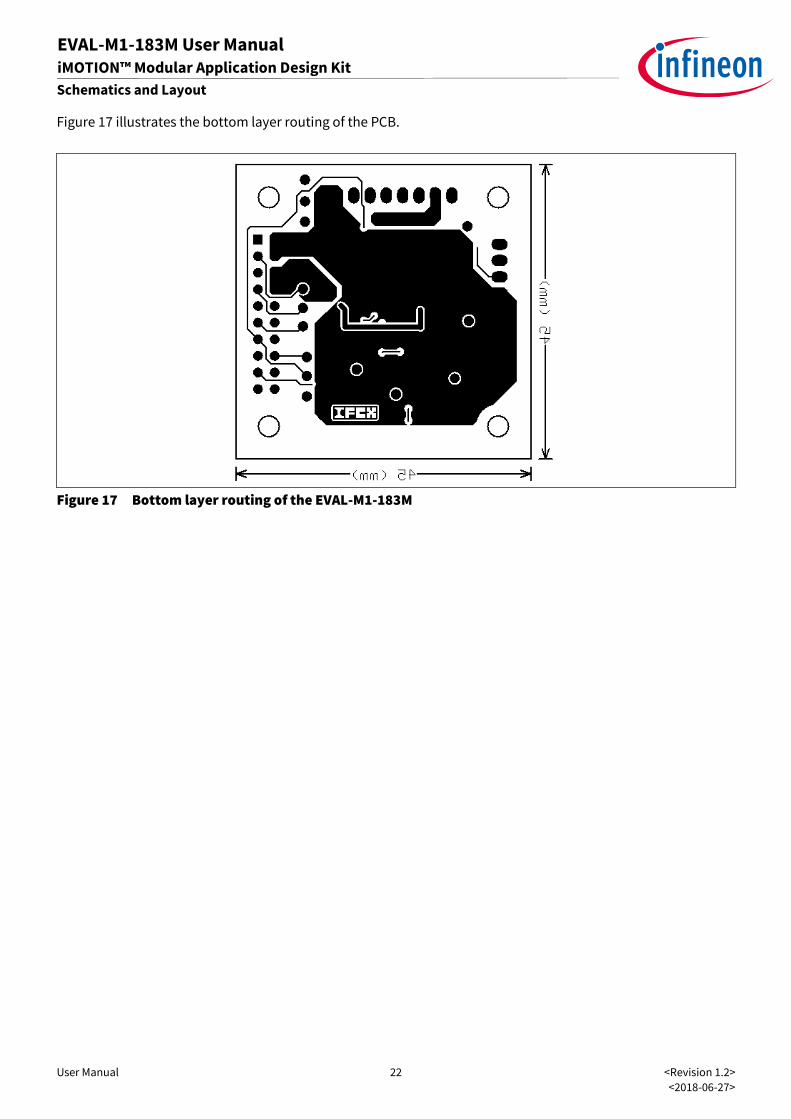
Figure 17 illustrates the bottom layer routing of the PCB.
Figure 17 Bottom layer routing of the EVAL-M1-183M
User Manual 23 <Revision 1.2>
<2018-06-27>
EVAL-M1-183M User Manual iMOTION™ Modular Application Design Kit
Bill of Materials of EVAL-M1-183M
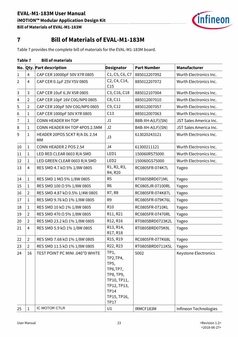
7 Bill of Materials of EVAL-M1-183M
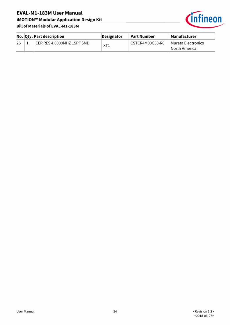
Table 7 provides the complete bill of materials for the EVAL-M1-183M board.
Table 7 Bill of materials
No. Qty. Part description Designator Part Number Manufacturer
1 4 CAP CER 10000pF 50V X7R 0805 C1, C5, C6, C7 885012207092 Wurth Electronics Inc.
2 4 CAP CER 0.1μF 25V Y5V 0805 C2, C4, C14,
C15 885012207072 Wurth Electronics Inc.
3 3 CAP CER 10uF 6.3V X5R 0805 C3, C16, C18 885012107004 Wurth Electronics Inc.
4 2 CAP CER 10pF 16V C0G/NP0 0805 C8, C11 885012007010 Wurth Electronics Inc.
5 2 CAP CER 100pF 50V C0G/NP0 0805 C9, C12 885012007057 Wurth Electronics Inc.
6 1 CAP CER 1000pF 50V X7R 0805 C13 885012007063 Wurth Electronics Inc.
7 1 CONN HEADER XH TOP J1 B8B-XH-A(LF)(SN) JST Sales America Inc.
8 1 CONN HEADER XH TOP 4POS 2.5MM J2 B4B-XH-A(LF)(SN) JST Sales America Inc.
9 1 HEADER 20POS SCKT R/A DL 2.54
MM J3
613020243121 Wurth Electronics Inc.
10 1 CONN HEADER 2 POS 2.54 J4 61300211121 Wurth Electronics Inc.
11 1 LED RED CLEAR 0603 R/A SMD LED1 150060RS75000 Wurth Electronics Inc.
12 1 LED GREEN CLEAR 0603 R/A SMD LED2 150060GS75000 Wurth Electronics Inc.
13 4 RES SMD 4.7 kΩ 5% 1/8W 0805 R1, R2, R3,
R4, R20 RC0805FR-074K7L Yageo
14 1 RES SMD 1 MΩ 5% 1/8W 0805 R5 RT0805BRD071ML Yageo
15 1 RES SMD 100 Ω 5% 1/8W 0805 R6 RC0805JR-07100RL Yageo
16 2 RES SMD 4.87 kΩ 0.5% 1/4W 0805 R7, R8 RC0805FR-074K87L Yageo
17 1 RES SMD 9.76 kΩ 1% 1/8W 0805 R9 RC0805FR-079K76L Yageo
18 1 RES SMD 10 kΩ 1% 1/8W 0805 R10 RC0805FR-0710KL Yageo
19 2 RES SMD 470 Ω 5% 1/8W 0805 R11, R21 RC0805FR-07470RL Yageo
20 2 RES SMD 23.2 kΩ 1% 1/8W 0805 R12, R16 RT0805BRD0723K2L Yageo
21 4 RES SMD 5.9 kΩ 1% 1/8W 0805 R13, R14,
R17, R18 RT0805BRD075K9L Yageo
22 2 RES SMD 7.68 kΩ 1% 1/8W 0805 R15, R19 RC0805FR-077K68L Yageo
23 2 RES SMD 11.5 kΩ 1% 1/8W 0805 R22, R23 RT0805BRD0711K5L Yageo
24 16 TEST POINT PC MINI .040"D WHITE TP1,
TP2,TP4,
TP5,
TP6,TP7,
TP8, TP9,
TP10, TP11,
TP12, TP13,
TP14
TP15, TP16,
TP17
5002 Keystone Electronics
25 1 IC MOTOR CTLR U1 IRMCF183M Infineon Technologies
User Manual 24 <Revision 1.2>
<2018-06-27>
EVAL-M1-183M User Manual iMOTION™ Modular Application Design Kit
Bill of Materials of EVAL-M1-183M
No. Qty. Part description Designator Part Number Manufacturer
26 1 CER RES 4.0000MHZ 15PF SMD XT1
CSTCR4M00G53-R0 Murata Electronics
North America
User Manual 25 <Revision 1.2>
<2018-06-27>
EVAL-M1-183M User Manual iMOTION™ Modular Application Design Kit
Reference
8 Reference
[1] Datasheet of Infineon IRMCF183M
[2] Application Note of 2017-03_AN2017-08_EVAL-M1-099M_V1.0_EN
[3] IRMCx100 Reference Manual
[4] IRMCx100 Software Developer’s Guide
[5] IRMCx100 System Overview
Note: All listed reference materials are available for download on Infineon’s website
www.infineon.com/. All the iMOTION MADK evaluation board’s User Manuals are available at
www.infineon.com/MADK
User Manual 26 <Revision 1.2>
<2018-06-27>
Revision History
EVAL-M1-183M User Manual iMOTION™ Modular Application Design Kit
Revision History
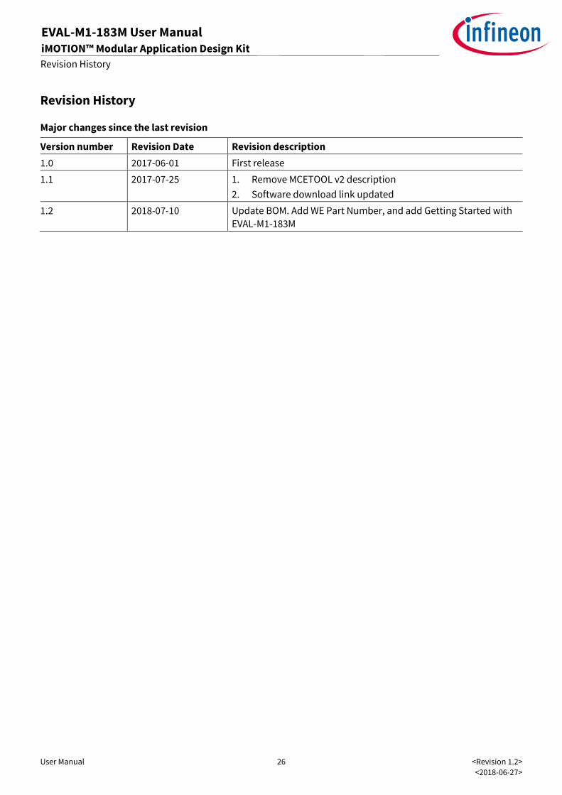
Major changes since the last revision
Version number Revision Date Revision description
1.0 2017-06-01 First release
1.1 2017-07-25 1. Remove MCETOOL v2 description
2. Software download link updated
1.2 2018-07-10 Update BOM. Add WE Part Number, and add Getting Started with
EVAL-M1-183M

Trademarks of Infineon Technologies AG AURIX™, C166™, CanPAK™, CIPOS™, CoolGaN™, CoolMOS™, CoolSET™, CoolSiC™, CORECONTROL™, CROSSAVE™, DAVE™, DI-POL™, DrBlade™, EasyPIM™, EconoBRIDGE™, EconoDUAL™, EconoPACK™, EconoPIM™, EiceDRIVER™, eupec™, FCOS™, HITFET™, HybridPACK™, Infineon™, ISOFACE™, IsoPACK™, i-Wafer™, MIPAQ™, ModSTACK™, my-d™, NovalithIC™, OmniTune™, OPTIGA™, OptiMOS™, ORIGA™, POWERCODE™, PRIMARION™, PrimePACK™, PrimeSTACK™, PROFET™, PRO-SIL™, RASIC™, REAL3™, ReverSave™, SatRIC™, SIEGET™, SIPMOS™, SmartLEWIS™, SOLID FLASH™, SPOC™, TEMPFET™, thinQ!™, TRENCHSTOP™, TriCore™.
Trademarks updated August 2015
Other Trademarks All referenced product or service names and trademarks are the property of their respective owners.
Edition <2018-06-27>
AN2017-13 EVAL-M1-183M User Manual
Published by
Infineon Technologies AG
81726 Munich, Germany
© 2018 Infineon Technologies AG.
All Rights Reserved.
Do you have a question about this
document?
Email: [email protected]
Document reference
IMPORTANT NOTICE The information contained in this application note is given as a hint for the implementation of the product only and shall in no event be regarded as a description or warranty of a certain functionality, condition or quality of the product. Before implementation of the product, the recipient of this application note must verify any function and other technical information given herein in the real application. Infineon Technologies hereby disclaims any and all warranties and liabilities of any kind (including without limitation warranties of non-infringement of intellectual property rights of any third party) with respect to any and all information given in this application note.
The data contained in this document is exclusively intended for technically trained staff. It is the responsibility of customer’s technical departments to evaluate the suitability of the product for the intended application and the completeness of the product information given in this document with respect to such application.
For further information on the product, technology, delivery terms and conditions and prices please contact your nearest Infineon Technologies office (www.infineon.com).
Please note that this product is not qualified according to the AEC Q100 or AEC Q101 documents of the Automotive Electronics Council.
WARNINGS Due to technical requirements products may contain dangerous substances. For information on the types in question please contact your nearest Infineon Technologies office.
Except as otherwise explicitly approved by Infineon Technologies in a written document signed by authorized representatives of Infineon Technologies, Infineon Technologies’ products may not be used in any applications where a failure of the product or any consequences of the use thereof can reasonably be expected to result in personal injury.

Mouser Electronics
Authorized Distributor
Click to View Pricing, Inventory, Delivery & Lifecycle Information: Infineon:
EVALM1183MTOBO1